US8000667B2 - System and method for compensating for modulation induced frequency shift during transmission of a radio frequency signal - Google Patents
System and method for compensating for modulation induced frequency shift during transmission of a radio frequency signalDownload PDFInfo
- Publication number
- US8000667B2 US8000667B2US11/346,991US34699106AUS8000667B2US 8000667 B2US8000667 B2US 8000667B2US 34699106 AUS34699106 AUS 34699106AUS 8000667 B2US8000667 B2US 8000667B2
- Authority
- US
- United States
- Prior art keywords
- frequency
- carrier signal
- signal
- transmitter
- carrier
- Prior art date
- Legal status (The legal status is an assumption and is not a legal conclusion. Google has not performed a legal analysis and makes no representation as to the accuracy of the status listed.)
- Active, expires
Links
Images


Classifications
- H—ELECTRICITY
- H04—ELECTRIC COMMUNICATION TECHNIQUE
- H04B—TRANSMISSION
- H04B1/00—Details of transmission systems, not covered by a single one of groups H04B3/00 - H04B13/00; Details of transmission systems not characterised by the medium used for transmission
- H04B1/06—Receivers
- H04B1/16—Circuits
- H04B1/20—Circuits for coupling gramophone pick-up, recorder output, or microphone to receiver
- H04B1/202—Circuits for coupling gramophone pick-up, recorder output, or microphone to receiver by remote control
- G—PHYSICS
- G08—SIGNALLING
- G08C—TRANSMISSION SYSTEMS FOR MEASURED VALUES, CONTROL OR SIMILAR SIGNALS
- G08C17/00—Arrangements for transmitting signals characterised by the use of a wireless electrical link
- G08C17/02—Arrangements for transmitting signals characterised by the use of a wireless electrical link using a radio link
- H—ELECTRICITY
- H03—ELECTRONIC CIRCUITRY
- H03L—AUTOMATIC CONTROL, STARTING, SYNCHRONISATION OR STABILISATION OF GENERATORS OF ELECTRONIC OSCILLATIONS OR PULSES
- H03L7/00—Automatic control of frequency or phase; Synchronisation
- G—PHYSICS
- G07—CHECKING-DEVICES
- G07C—TIME OR ATTENDANCE REGISTERS; REGISTERING OR INDICATING THE WORKING OF MACHINES; GENERATING RANDOM NUMBERS; VOTING OR LOTTERY APPARATUS; ARRANGEMENTS, SYSTEMS OR APPARATUS FOR CHECKING NOT PROVIDED FOR ELSEWHERE
- G07C9/00—Individual registration on entry or exit
- G07C9/00174—Electronically operated locks; Circuits therefor; Nonmechanical keys therefor, e.g. passive or active electrical keys or other data carriers without mechanical keys
- G07C2009/00753—Electronically operated locks; Circuits therefor; Nonmechanical keys therefor, e.g. passive or active electrical keys or other data carriers without mechanical keys operated by active electrical keys
- G07C2009/00769—Electronically operated locks; Circuits therefor; Nonmechanical keys therefor, e.g. passive or active electrical keys or other data carriers without mechanical keys operated by active electrical keys with data transmission performed by wireless means
- G07C2009/00793—Electronically operated locks; Circuits therefor; Nonmechanical keys therefor, e.g. passive or active electrical keys or other data carriers without mechanical keys operated by active electrical keys with data transmission performed by wireless means by Hertzian waves
- G—PHYSICS
- G07—CHECKING-DEVICES
- G07C—TIME OR ATTENDANCE REGISTERS; REGISTERING OR INDICATING THE WORKING OF MACHINES; GENERATING RANDOM NUMBERS; VOTING OR LOTTERY APPARATUS; ARRANGEMENTS, SYSTEMS OR APPARATUS FOR CHECKING NOT PROVIDED FOR ELSEWHERE
- G07C2209/00—Indexing scheme relating to groups G07C9/00 - G07C9/38
- G07C2209/60—Indexing scheme relating to groups G07C9/00174 - G07C9/00944
- G07C2209/61—Signal comprising different frequencies, e.g. frequency hopping
Definitions
- the present inventionrelates generally to the field of electronic transmitters and transceivers for use with vehicles. More specifically, the present invention relates to electronic transceivers that are configured for use with remote control systems.
- Electronically operated remote control systemssuch as garage door opener systems, home security systems, home lighting systems, gate controllers, etc., typically employ a portable, hand-held transmitter (i.e., an original transmitter) to transmit a control signal to a receiver located at the remote control system.
- a garage door opener systemtypically includes a receiver located within a home owner's garage and coupled to the garage door opener.
- a userpresses a button on the original transmitter to transmit a radio frequency signal to the receiver to activate the garage door opener to open and close a garage door.
- the receiveris tuned to the frequency of its associated original transmitter and demodulates a predetermined code programmed into both the original transmitter and the receiver for operating the garage door.
- a trainable transmitter or transceivermay be provided in a vehicle for use with remote control systems.
- a trainable transmitteris configurable by a user to activate one or more of a plurality of different wireless control system receivers using different radio frequency messages.
- a usermay train the trainable transmitter to an existing original transmitter by holding the two transmitters in close range and pressing buttons on the original transmitter and the trainable transmitter.
- the trainable transmitteridentifies the type of remote control system associated with the original transmitter based on a radio frequency signal received from the original transmitter. For example, the trainable transmitter may identify and store the control code and carrier frequency of the original transmitter radio frequency (“RF”) control signal.
- the receivermay learn a transmitter identifier of the trainable transmitter.
- the trainable transceiver and receivermust also be “synchronized” so that the counters of the trainable transmitter and the receiver begin at the same value. Accordingly, the user presses a button on the remote control system receiver to put the receiver in a training mode. A button on the trainable transceiver may then be pressed, for example, two to three times, to transmit messages so the receiver may learn the transmitter identifier, complete synchronization of the receiver and the trainable transmitter and confirm that training was successful. Once trained, the trainable transceiver may be used to transmit RF signals to control the remote control system.
- a userpresses an input device, e.g., a button, of the trainable transmitter that has been trained to a particular remote control system, for example, a garage door opener.
- the trainable transmitterretrieves the frequency and control data associated with the button pressed, generates a carrier signal with the appropriate carrier frequency and modulates control data on the carrier signal to generate an RF control signal to control the garage door opener.
- the RF control signalis then transmitted to the garage door opener.
- various RF characteristics of the trainable transmitter circuitrye.g., RF characteristics of an Application Specific Integrated Circuit (ASIC) used for the RF circuitry
- ASICApplication Specific Integrated Circuit
- RF characteristicsmay cause a frequency shift during periods when data is modulated on the RF carrier signal.
- the frequency shiftresults in a wider bandwidth of the transmitted RF control signal.
- the receiving bandwidth of a receiver associated with a remote control systemmay be relatively narrow. Therefore, the wider bandwidth of the RF control signal caused by a shift in carrier frequency may adversely affect performance of the transmitter and the ability of a remote control system receiver to receive and respond to the RF control signal transmitted by the transmitter.
- an electronic transmittermay be described herein with reference to systems for trainable transmitters or rolling code transmitters, one or more of the systems and methods for compensating for frequency shifting may be applied to, and find utility in, other types of transmitters as well.
- one or more of the systems for compensating for frequency shiftingmay be suitable for use with fixed code transmitters, single frequency transmitters, etc., all of which may require some form of compensation for frequency shifting.
- a method for compensating for frequency shifts during transmission of an RF control signalincludes receiving a request to enter a transmission mode from a user, generating a carrier signal having a frequency, measuring the frequency of the carrier signal, and comparing the measured frequency of the carrier signal to a desired frequency. The method includes determining if there is a difference between the measured frequency and the desired frequency, and if so, determining if data is being modulated on the carrier signal. The method further includes applying a correction to the carrier signal frequency if data is not being modulated on the carrier signal.
- the systemalso includes a voltage controlled oscillator circuit coupled to transceiver, such that the voltage controlled oscillator circuit is configured to generate a control signal, including a carrier frequency.
- the systemfurther includes a control circuit coupled to the voltage controlled oscillator circuit, such that the control circuit is configured to measure the carrier frequency of the control signal generated by the voltage controlled oscillator circuit.
- the carrier frequency of the control signalis compared to a desired frequency of the remote electronic device, such that if a difference exists between the value of the carrier frequency and the desired frequency, the control circuit determines if data is being modulated onto the carrier frequency of the control signal.
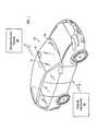
- FIG. 1is a perspective view of a vehicle having an electronic transmitter in accordance with an embodiment.
- FIG. 2is a schematic block diagram of an electronic transmitter in accordance with an embodiment.
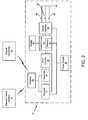
- FIG. 3illustrates a method for compensating for frequency shifts during transmission of an RF signal in accordance with an embodiment.
- FIG. 1is a perspective view of a vehicle including an electronic transmitter in accordance with an embodiment.
- a vehicle 10which may be an automobile, truck, sport utility vehicle (SUV), mini-van, or other vehicle, includes an electronic transmitter 16 .
- an electronic transmittermay be embodied in other systems such as a portable housing, key fob, key chain or other hand-held device.
- electronic transmitter 16is illustrated mounted to an overhead console of vehicle 10 .
- one or more of the elements of electronic transmitter 16may be mounted to other vehicle interior elements such as a visor 17 , an instrument panel 18 , a rearview mirror (not shown), a dashboard, seat, center console, door panel, or other appropriate location in the vehicle.
- Electronic transmitter 16may be configured to control a remote control system 14 , such as a garage door opener, home security system, home lighting system, gate controller, etc.
- Electronic transmitter 16is trained using an original transmitter 12 used to control remote control system 14 .
- Original transmitter 12is a transmitter, typically a hand-held transmitter, which is sold with remote control system 14 or as an after-market item, and which is configured to transmit an activation signal at a predetermined carrier frequency and having control data configured to actuate remote control system 14 .
- original transmitter 12can be a hand-held garage door opener transmitter configured to transmit a garage door opener signal at a frequency, such as 355 Megahertz (MHz), wherein the activation signal has control data, which can be fixed code or cryptographically-encoded code (e.g., a rolling code).
- remote control system 14may be a garage door opener system configured to open a garage door in response to receiving the activation signal from original transmitter 12 .
- remote control system 14includes an antenna (not shown) for receiving wireless signals including control data which would control remote control system 14 .
- an activation or control signal Ais transmitted from original transmitter 12 to electronic transmitter 16 in the vehicle 10 .
- Electronic transmitter 16receives the control signal, identifies the control data (e.g., fixed or rolling code data) and carrier frequency of the control signal and stores this information for later retransmission.
- Electronic transmitter 16may then be used to selectively generate and transmit a control signal T with the learned frequency and control data to the remote control system 14 , such as a garage door opener, that is responsive to the control signal.
- the remote control system 14such as a garage door opener
- FIG. 2is a schematic block diagram of an electronic transmitter in accordance with an embodiment.
- Electronic transmitter 16includes a transmitter circuit 20 and a receiver 21 that are coupled to an antenna 38 .
- a single dual function transceiver having transmit and receive circuitrymay be provided in place of a separate receiver and transmitter.
- Transmitter circuit 20 and receiver 21are also coupled to voltage controlled oscillator circuitry (“VCO”) 40 , hereinafter referred to as VCO circuitry 40 , and control circuit 22 .
- VCOvoltage controlled oscillator circuitry
- Control circuit 22may include various types of control circuitry, digital and/or analog, and may include a microprocessor, microcontroller, application specific integrated circuit (ASIC), or other digital and/or analog circuitry configured to perform various input/output, control, analysis, and other functions to be described herein.
- VCOvoltage controlled oscillator circuitry
- VCO circuitry 40is configured to generate a carrier signal at a specific frequency (e.g., the frequency identified or learned in a training mode) during training and transmission modes of the transmitter 16 .
- a specific frequencye.g., the frequency identified or learned in a training mode
- the carrier signal generated by the VCO circuitry 40is modulated with control data supplied by control circuit 22 .
- a switch interface 24is coupled to a plurality of buttons or switches. Alternatively, other user input devices such as knobs, dials, etc., or a voice actuated input control circuit configured to receive voice signals from a vehicle occupant may be provided to receive user input.
- switch interface 24is coupled to one terminal of each of three push button switches 26 , 28 and 30 , which have their remaining terminal connected to ground.
- Switches 26 , 28 and 30may each be associated with a separate remote control system to be controlled, each of which may have its own unique operating RF frequency, modulation scheme, and/or control data.
- switches 26 , 28 and 30each correspond to a different radio frequency channel for transmitter circuit 20 . It should be understood, however, that each channel may be trained to the same original transmitter, if desired, or to different original transmitters.
- Switch interface 24couples signal information from switches 26 , 28 and 30 to the input terminals of control circuit 22 .
- Control circuit 22includes data input terminals for receiving signals from the switch interface 24 indicative of the closure states of switches 26 , 28 and 30 .
- a power supply 32is conventionally coupled to the various components for supplying the necessary operating power in a conventional manner.
- Control circuit 22is also coupled to a display 36 which includes a display element such as a light emitting diode (LED).
- Display 36may alternatively include other display elements, such as a liquid crystal display (LCD), a vacuum fluorescent display (VFD), or other display elements.
- Control circuit 22includes a memory 34 including volatile and/or non-volatile memory to, for example, store a computer program or other software to perform the functions described herein.
- Memory 34is configured to store learned information such as control data and carrier frequency information that may be associated with switches 26 , 28 and 30 .
- each switch or button 26 , 28 and 30may be associated with a separate remote control system, such as different garage door openers, electronically operated access gates, house lighting controls and other remote control systems, each which may have its own unique operating RF frequency, modulation scheme and control data.
- Transmitter circuit 20 and receiver 21communicate with the remote control system 14 and the original transmitter 12 via antenna 38 .
- Receiver 21may be used to receive signals via antenna 38 and transmitter circuit 20 may be used to transmit signals via antenna 38 .
- a separate antennamay be used with transmitter 20 and with receiver 21 (e.g., separate transmit and receive antennas may be provided in the electronic transmitter).
- electronic transmitter 16is configured to transmit a wireless control signal having control data that will control remote control system 14 .
- VCO circuitry 40 and transmitter circuit 20are configured, under control from control circuit 22 , to generate a control signal having a carrier frequency and control data associated with the particular trained channel.
- VCO circuitry 40generate a carrier signal at the selected frequency for the trained channel and then the control data is modulated on the carrier signal.
- the control datamay be modulated onto the control signal using, for example, frequency shift key (FSK) modulation, amplitude shift key (ASK) modulation or other modulation technique.
- the control data on the control signalmay be a fixed code or a rolling code or other cryptographically encoded control code suitable for use with remote control system 14 .
- electronic transmitter 16may learn the control code and carrier frequency for remote control system using original transmitter 12 for remote control system 14 .
- the control signalmay then be transmitted via antenna 38 to the remote control system 14 .
- the carrier frequencymay be shifted from the desired frequency as a result of RF characteristics of the circuitry of the electronic transmitter 16 .
- RF components of electronic transmitter 16may be implemented on an ASIC (application specific integrated circuit). RF characteristics of the ASIC may cause a frequency shift in the frequency of the carrier signal generated by VCO circuitry 40 (shown in FIG. 2 ) which can result in a wider bandwidth (e.g., the effective bandwidth) of the transmitted control signal.
- ASICapplication specific integrated circuit
- a request to transmit an RF control signal(e.g., to enter a transmission mode) is received from a user at the electronic transmitter 16 .
- a usermay provide a request by actuating a pushbutton (e.g., pushbutton 26 shown in FIG. 2 ) of the electronic transmitter.
- a displaymay be used to indicate to the user that a transmission mode was initiated, for example, a display element such as an LED indicator may be lit or flash to provide feedback to the user.
- a request to enter a transmission modemay be provided by a combination of key presses using input devices of the electronic transmitter, by receiving a message on a vehicle bus, or by selecting a menu item on a display, such as on a user interface.
- the frequency and control data associated with the user inputis retrieved from memory.
- a carrier signalis generated at the retrieved frequency by VCO circuitry 40 (shown in FIG. 2 ).
- the frequency of the carrier signalis measured, for example, control circuit 22 (shown in FIG. 2 ) may be configured to measure the frequency of the carrier signal. The measured frequency is then compared to the desired frequency value in step 310 to determine if there is a difference. If there is not a difference, at step 312 , the measurement and comparison steps are repeated for the duration of the signal transmission.
- step 312it is determined whether data is being modulated onto the carrier signal at step 314 . If data is not being modulated, a correction factor (e.g., a correction pulse) is applied to the VCO circuitry 40 at step 316 to adjust the frequency of the carrier signal up or down as needed to keep the frequency as close to the desired frequency as possible. The measurement and comparison steps are repeated for the duration of the signal transmission. If data is being modulated onto the carrier signal, a correction is not applied to the VCO circuitry at step 318 and the measurement and comparison steps are repeated.
- a correction factore.g., a correction pulse
- a correction factormay be applied to the VCO circuitry 40 (at step 316 ) to adjust the frequency of the carrier signal when data is being modulated. If data is not being modulated onto the carrier signal, a correction factor is not be applied to the VCO circuitry (at step 318 ).
Landscapes
- Engineering & Computer Science (AREA)
- Computer Networks & Wireless Communication (AREA)
- Physics & Mathematics (AREA)
- General Physics & Mathematics (AREA)
- Signal Processing (AREA)
- Selective Calling Equipment (AREA)
- Lock And Its Accessories (AREA)
Abstract
Description
Claims (19)
Priority Applications (4)
| Application Number | Priority Date | Filing Date | Title |
|---|---|---|---|
| US11/346,991US8000667B2 (en) | 2006-02-03 | 2006-02-03 | System and method for compensating for modulation induced frequency shift during transmission of a radio frequency signal |
| EP07763536AEP1994646A1 (en) | 2006-02-03 | 2007-02-02 | System and method for compensating for modulation induced frequency shift during transmission of a radio frequency signal |
| CN200780010883.2ACN101411076B (en) | 2006-02-03 | 2007-02-02 | Systems and methods for compensating for modulation-induced frequency offset during transmission of radio frequency signals |
| PCT/US2007/002833WO2007092282A1 (en) | 2006-02-03 | 2007-02-02 | System and method for compensating for modulation induced frequency shift during transmission of a radio frequency signal |
Applications Claiming Priority (1)
| Application Number | Priority Date | Filing Date | Title |
|---|---|---|---|
| US11/346,991US8000667B2 (en) | 2006-02-03 | 2006-02-03 | System and method for compensating for modulation induced frequency shift during transmission of a radio frequency signal |
Publications (2)
| Publication Number | Publication Date |
|---|---|
| US20070197172A1 US20070197172A1 (en) | 2007-08-23 |
| US8000667B2true US8000667B2 (en) | 2011-08-16 |
Family
ID=38181095
Family Applications (1)
| Application Number | Title | Priority Date | Filing Date |
|---|---|---|---|
| US11/346,991Active2027-11-26US8000667B2 (en) | 2006-02-03 | 2006-02-03 | System and method for compensating for modulation induced frequency shift during transmission of a radio frequency signal |
Country Status (4)
| Country | Link |
|---|---|
| US (1) | US8000667B2 (en) |
| EP (1) | EP1994646A1 (en) |
| CN (1) | CN101411076B (en) |
| WO (1) | WO2007092282A1 (en) |
Cited By (8)
| Publication number | Priority date | Publication date | Assignee | Title |
|---|---|---|---|---|
| US9576408B2 (en) | 2014-07-30 | 2017-02-21 | Gentex Corporation | Battery powered trainable remote garage door opener module |
| US9715772B2 (en) | 2013-11-15 | 2017-07-25 | Gentex Corporation | Internet-connected garage door control system |
| US10997810B2 (en) | 2019-05-16 | 2021-05-04 | The Chamberlain Group, Inc. | In-vehicle transmitter training |
| US11024192B2 (en) | 2016-06-07 | 2021-06-01 | Gentex Corporation | Vehicle trainable transceiver for allowing cloud-based transfer of data between vehicles |
| US11074773B1 (en) | 2018-06-27 | 2021-07-27 | The Chamberlain Group, Inc. | Network-based control of movable barrier operators for autonomous vehicles |
| US11220856B2 (en) | 2019-04-03 | 2022-01-11 | The Chamberlain Group Llc | Movable barrier operator enhancement device and method |
| US11423717B2 (en) | 2018-08-01 | 2022-08-23 | The Chamberlain Group Llc | Movable barrier operator and transmitter pairing over a network |
| US11778464B2 (en) | 2017-12-21 | 2023-10-03 | The Chamberlain Group Llc | Security system for a moveable barrier operator |
Families Citing this family (27)
| Publication number | Priority date | Publication date | Assignee | Title |
|---|---|---|---|---|
| WO2005002080A1 (en)* | 2003-05-28 | 2005-01-06 | Johnson Controls Technology Company | System and method for receiving data for training a trainable transmitter |
| US7922086B2 (en) | 2004-09-30 | 2011-04-12 | The Invention Science Fund I, Llc | Obtaining user assistance |
| US10687166B2 (en) | 2004-09-30 | 2020-06-16 | Uber Technologies, Inc. | Obtaining user assistance |
| US10514816B2 (en) | 2004-12-01 | 2019-12-24 | Uber Technologies, Inc. | Enhanced user assistance |
| US10445799B2 (en) | 2004-09-30 | 2019-10-15 | Uber Technologies, Inc. | Supply-chain side assistance |
| US8180293B2 (en)* | 2006-03-24 | 2012-05-15 | The Invention Science Fund I, Llc | Vehicle control and communication via device in proximity |
| US8538331B2 (en)* | 2006-03-24 | 2013-09-17 | The Invention Science Fund I, LC | Vehicle control and communication via device in proximity |
| US8358976B2 (en) | 2006-03-24 | 2013-01-22 | The Invention Science Fund I, Llc | Wireless device with an aggregate user interface for controlling other devices |
| US8126400B2 (en)* | 2006-03-24 | 2012-02-28 | The Invention Science Fund I, Llc | Method for an aggregate user interface for controlling other devices |
| US8195106B2 (en)* | 2006-05-31 | 2012-06-05 | The Invention Science Fund I, Llc | Vehicle control and communication via device in proximity |
| JP5676108B2 (en) | 2006-12-20 | 2015-02-25 | ジョンソン コントロールズ テクノロジー カンパニーJohnson Controls Technology Company | Remote display reproduction system |
| PL2092275T3 (en)* | 2006-12-20 | 2013-03-29 | Johnson Controls Tech Co | System and method for providing route calculation and information to a vehicle |
| US9587958B2 (en)* | 2007-01-23 | 2017-03-07 | Visteon Global Technologies, Inc. | Mobile device gateway systems and methods |
| US9324230B2 (en)* | 2008-12-04 | 2016-04-26 | Gentex Corporation | System and method for configuring a wireless control system of a vehicle using induction field communication |
| JP5623287B2 (en) | 2007-12-05 | 2014-11-12 | ジョンソン コントロールズテクノロジーカンパニーJohnson Controls Technology Company | Vehicle user interface system and method |
| US8970352B2 (en)* | 2012-10-23 | 2015-03-03 | GM Global Technology Operations LLC | Remote activated garage door opener functions via a graphical user interface in a vehicle |
| US9443422B2 (en)* | 2012-11-07 | 2016-09-13 | Gentex Corporation | Frequency shifting method for universal transmitters |
| CN106537476A (en)* | 2014-04-18 | 2017-03-22 | 金泰克斯公司 | Trainable transceiver and mobile communications device diagnostic systems and methods |
| US9483744B2 (en) | 2014-05-06 | 2016-11-01 | Elwha Llc | Real-time carpooling coordinating systems and methods |
| US11100434B2 (en) | 2014-05-06 | 2021-08-24 | Uber Technologies, Inc. | Real-time carpooling coordinating system and methods |
| US9552559B2 (en) | 2014-05-06 | 2017-01-24 | Elwha Llc | System and methods for verifying that one or more directives that direct transport of a second end user does not conflict with one or more obligations to transport a first end user |
| US10458801B2 (en) | 2014-05-06 | 2019-10-29 | Uber Technologies, Inc. | Systems and methods for travel planning that calls for at least one transportation vehicle unit |
| SI3195285T1 (en)* | 2014-09-19 | 2018-04-30 | Silca S.P.A. | Procedure for creating enhanced radio-controlled variable control |
| SG10201509972YA (en)* | 2015-12-04 | 2016-09-29 | Huawei Internat Pte Ltd | Asynchronous transmission for nfc card emulation mode |
| WO2020222174A1 (en)* | 2019-04-30 | 2020-11-05 | Gentex Corporation | Vehicle trainable transceiver having a programmable oscillator |
| US20200410794A1 (en)* | 2019-06-25 | 2020-12-31 | Microchip Technology Incorporated | Configurable access controller, and related systems, methods, and devices |
| WO2025171572A1 (en)* | 2024-02-16 | 2025-08-21 | Qualcomm Incorporated | Frequency synchronization for ambient devices |
Citations (9)
| Publication number | Priority date | Publication date | Assignee | Title |
|---|---|---|---|---|
| US4587498A (en)* | 1983-03-07 | 1986-05-06 | Telecummunications Radioelectriques et Telephoniques T.R.T. | Circuit for recovering the carrier of an amplitude-and-phase-modulated input signal |
| DE3912814C1 (en) | 1989-04-19 | 1990-07-26 | Ant Nachrichtentechnik Gmbh, 7150 Backnang, De | Radio call system - compares ref. signal with unmodulated output to obtain oscillator control voltage |
| US5390216A (en)* | 1991-11-02 | 1995-02-14 | Robert Bosch Gmbh | Synchronization method for a mobile radiotelephone |
| US5661804A (en) | 1995-06-27 | 1997-08-26 | Prince Corporation | Trainable transceiver capable of learning variable codes |
| US6091343A (en)* | 1997-12-18 | 2000-07-18 | Prince Corporation | Trainable RF transmitter having expanded learning capabilities |
| US6268780B1 (en)* | 2000-04-26 | 2001-07-31 | National Semiconductor Corporation | Frequency synthesizer with digital frequency lock loop |
| US6397186B1 (en)* | 1999-12-22 | 2002-05-28 | Ambush Interactive, Inc. | Hands-free, voice-operated remote control transmitter |
| WO2002075927A2 (en) | 2001-03-20 | 2002-09-26 | Infineon Technologies Ag | Frequency closed loop for frequency modulation |
| US6603821B1 (en)* | 1999-11-12 | 2003-08-05 | Mitsubishi Denki Kabushiki Kaisha | Wireless communication terminal capable of correctly specifying position of burst and having small frequency error of recovered carrier |
- 2006
- 2006-02-03USUS11/346,991patent/US8000667B2/enactiveActive
- 2007
- 2007-02-02CNCN200780010883.2Apatent/CN101411076B/enactiveActive
- 2007-02-02EPEP07763536Apatent/EP1994646A1/ennot_activeWithdrawn
- 2007-02-02WOPCT/US2007/002833patent/WO2007092282A1/enactiveApplication Filing
Patent Citations (9)
| Publication number | Priority date | Publication date | Assignee | Title |
|---|---|---|---|---|
| US4587498A (en)* | 1983-03-07 | 1986-05-06 | Telecummunications Radioelectriques et Telephoniques T.R.T. | Circuit for recovering the carrier of an amplitude-and-phase-modulated input signal |
| DE3912814C1 (en) | 1989-04-19 | 1990-07-26 | Ant Nachrichtentechnik Gmbh, 7150 Backnang, De | Radio call system - compares ref. signal with unmodulated output to obtain oscillator control voltage |
| US5390216A (en)* | 1991-11-02 | 1995-02-14 | Robert Bosch Gmbh | Synchronization method for a mobile radiotelephone |
| US5661804A (en) | 1995-06-27 | 1997-08-26 | Prince Corporation | Trainable transceiver capable of learning variable codes |
| US6091343A (en)* | 1997-12-18 | 2000-07-18 | Prince Corporation | Trainable RF transmitter having expanded learning capabilities |
| US6603821B1 (en)* | 1999-11-12 | 2003-08-05 | Mitsubishi Denki Kabushiki Kaisha | Wireless communication terminal capable of correctly specifying position of burst and having small frequency error of recovered carrier |
| US6397186B1 (en)* | 1999-12-22 | 2002-05-28 | Ambush Interactive, Inc. | Hands-free, voice-operated remote control transmitter |
| US6268780B1 (en)* | 2000-04-26 | 2001-07-31 | National Semiconductor Corporation | Frequency synthesizer with digital frequency lock loop |
| WO2002075927A2 (en) | 2001-03-20 | 2002-09-26 | Infineon Technologies Ag | Frequency closed loop for frequency modulation |
Non-Patent Citations (2)
| Title |
|---|
| European Office Action for Application No. 07763536.5, dated Feb. 17, 2009, 3 pages. |
| International Search Report and Written Opinion for International Patent Application No. PCT/US2007/002833, mailed Jul. 25, 2007, 23 pages. |
Cited By (16)
| Publication number | Priority date | Publication date | Assignee | Title |
|---|---|---|---|---|
| US9715772B2 (en) | 2013-11-15 | 2017-07-25 | Gentex Corporation | Internet-connected garage door control system |
| US10339734B2 (en) | 2013-11-15 | 2019-07-02 | Gentex Corporation | Internet-connected garage door control system |
| US10134213B2 (en) | 2014-07-30 | 2018-11-20 | Gentex Corporation | Battery powered trainable remote garage door opener module |
| US9576408B2 (en) | 2014-07-30 | 2017-02-21 | Gentex Corporation | Battery powered trainable remote garage door opener module |
| US11024192B2 (en) | 2016-06-07 | 2021-06-01 | Gentex Corporation | Vehicle trainable transceiver for allowing cloud-based transfer of data between vehicles |
| US12108248B2 (en) | 2017-12-21 | 2024-10-01 | The Chamberlain Group Llc | Security system for a moveable barrier operator |
| US11778464B2 (en) | 2017-12-21 | 2023-10-03 | The Chamberlain Group Llc | Security system for a moveable barrier operator |
| US11763616B1 (en) | 2018-06-27 | 2023-09-19 | The Chamberlain Group Llc | Network-based control of movable barrier operators for autonomous vehicles |
| US11074773B1 (en) | 2018-06-27 | 2021-07-27 | The Chamberlain Group, Inc. | Network-based control of movable barrier operators for autonomous vehicles |
| US12056971B1 (en) | 2018-06-27 | 2024-08-06 | The Chamberlain Group Llc. | Network-based control of movable barrier operators for autonomous vehicles |
| US11869289B2 (en) | 2018-08-01 | 2024-01-09 | The Chamberlain Group Llc | Movable barrier operator and transmitter pairing over a network |
| US11423717B2 (en) | 2018-08-01 | 2022-08-23 | The Chamberlain Group Llc | Movable barrier operator and transmitter pairing over a network |
| US12354422B2 (en) | 2018-08-01 | 2025-07-08 | The Chamberlain Group Llc | Movable barrier operator and transmitter pairing over a network |
| US11220856B2 (en) | 2019-04-03 | 2022-01-11 | The Chamberlain Group Llc | Movable barrier operator enhancement device and method |
| US11462067B2 (en) | 2019-05-16 | 2022-10-04 | The Chamberlain Group Llc | In-vehicle transmitter training |
| US10997810B2 (en) | 2019-05-16 | 2021-05-04 | The Chamberlain Group, Inc. | In-vehicle transmitter training |
Also Published As
| Publication number | Publication date |
|---|---|
| CN101411076A (en) | 2009-04-15 |
| US20070197172A1 (en) | 2007-08-23 |
| EP1994646A1 (en) | 2008-11-26 |
| CN101411076B (en) | 2013-06-19 |
| WO2007092282A1 (en) | 2007-08-16 |
Similar Documents
| Publication | Publication Date | Title |
|---|---|---|
| US8000667B2 (en) | System and method for compensating for modulation induced frequency shift during transmission of a radio frequency signal | |
| US7889050B2 (en) | System and method for training a trainable transmitter | |
| US7786843B2 (en) | System and method for training a trainable transmitter and a remote control system receiver | |
| US7864070B2 (en) | System and method for training a trainable transmitter | |
| EP1872350B1 (en) | System and method for determining a receiver threshold for a trainable transmitter system | |
| US8253528B2 (en) | Trainable transceiver system | |
| US8531266B2 (en) | System and method for providing an in-vehicle transmitter having multi-colored LED | |
| US7911358B2 (en) | System and method for enrollment of a remotely controlled device in a trainable transmitter | |
| US8330569B2 (en) | System and method for receiving data for training a trainable transmitter | |
| US9443422B2 (en) | Frequency shifting method for universal transmitters |
Legal Events
| Date | Code | Title | Description |
|---|---|---|---|
| AS | Assignment | Owner name:JOHNSON CONTROLS TECHNOLOGY COMPANY, MICHIGAN Free format text:ASSIGNMENT OF ASSIGNORS INTEREST;ASSIGNORS:WITKOWSKI, TODD R.;REENE, JASON L.;REEL/FRAME:017588/0007 Effective date:20060508 | |
| STCF | Information on status: patent grant | Free format text:PATENTED CASE | |
| AS | Assignment | Owner name:GENTEX CORPORATION, MICHIGAN Free format text:ASSIGNMENT OF ASSIGNORS INTEREST;ASSIGNOR:GENTEX CORPORATION;REEL/FRAME:032471/0695 Effective date:20130927 | |
| AS | Assignment | Owner name:GENTEX CORPORATION, MICHIGAN Free format text:CORRECTIVE ASSIGNMENT TO CORRECT THE PATENT # 5703941 IS INCORRECT AND SHOULD BE 6703941. PATENT # 6330569 IS INCORRECT AND SHOULD BE 8330569. PREVIOUSLY RECORDED ON REEL 032471 FRAME 0695. ASSIGNOR(S) HEREBY CONFIRMS THE ASSIGNMENT OF ASSIGNORS INTEREST;ASSIGNOR:GENTEX CORPORATION;REEL/FRAME:032514/0564 Effective date:20130927 | |
| AS | Assignment | Owner name:GENTEX CORPORATION, MICHIGAN Free format text:CORRECTIVE ASSIGNMENT TO CORRECT THE ASSIGNOR, SHOULD BE JOHNSON CONTROLS TECHNOLOGY COMPANY. ADDITIONAL CORRECTIVE ASSIGNMENT RECORDED @ 032514/0564. PREVIOUSLY RECORDED ON REEL 032471 FRAME 0695. ASSIGNOR(S) HEREBY CONFIRMS THE ASSIGNMENT OF ASSIGNORS INTEREST;ASSIGNOR:JOHNSON CONTROLS TECHNOLOGY COMPANY;REEL/FRAME:032621/0757 Effective date:20130927 | |
| AS | Assignment | Owner name:GENTEX CORPORATION, MICHIGAN Free format text:CORRECTIVE ASSIGNMENT TO CORRECT THE ASSIGNOR, IT SHOULD BE JOHNSON CONTROLS TECHNOLOGY COMPANY. PREVIOUSLY RECORDED ON REEL 032514 FRAME 0564. ASSIGNOR(S) HEREBY CONFIRMS THE ASSIGNMENT OF ASSIGNORS INTEREST;ASSIGNOR:JOHNSON CONTROLS TECHNOLOGY COMPANY;REEL/FRAME:032664/0688 Effective date:20130927 | |
| FPAY | Fee payment | Year of fee payment:4 | |
| MAFP | Maintenance fee payment | Free format text:PAYMENT OF MAINTENANCE FEE, 8TH YEAR, LARGE ENTITY (ORIGINAL EVENT CODE: M1552); ENTITY STATUS OF PATENT OWNER: LARGE ENTITY Year of fee payment:8 | |
| MAFP | Maintenance fee payment | Free format text:PAYMENT OF MAINTENANCE FEE, 12TH YEAR, LARGE ENTITY (ORIGINAL EVENT CODE: M1553); ENTITY STATUS OF PATENT OWNER: LARGE ENTITY Year of fee payment:12 |