US8000485B2 - Virtual audio processing for loudspeaker or headphone playback - Google Patents
Virtual audio processing for loudspeaker or headphone playbackDownload PDFInfo
- Publication number
- US8000485B2 US8000485B2US12/762,915US76291510AUS8000485B2US 8000485 B2US8000485 B2US 8000485B2US 76291510 AUS76291510 AUS 76291510AUS 8000485 B2US8000485 B2US 8000485B2
- Authority
- US
- United States
- Prior art keywords
- channel signal
- signal
- output
- center
- audio
- Prior art date
- Legal status (The legal status is an assumption and is not a legal conclusion. Google has not performed a legal analysis and makes no representation as to the accuracy of the status listed.)
- Expired - Fee Related, expires
Links
Images


Classifications
- H—ELECTRICITY
- H04—ELECTRIC COMMUNICATION TECHNIQUE
- H04S—STEREOPHONIC SYSTEMS
- H04S3/00—Systems employing more than two channels, e.g. quadraphonic
- H—ELECTRICITY
- H04—ELECTRIC COMMUNICATION TECHNIQUE
- H04S—STEREOPHONIC SYSTEMS
- H04S3/00—Systems employing more than two channels, e.g. quadraphonic
- H04S3/002—Non-adaptive circuits, e.g. manually adjustable or static, for enhancing the sound image or the spatial distribution
- H—ELECTRICITY
- H04—ELECTRIC COMMUNICATION TECHNIQUE
- H04S—STEREOPHONIC SYSTEMS
- H04S2400/00—Details of stereophonic systems covered by H04S but not provided for in its groups
- H04S2400/01—Multi-channel, i.e. more than two input channels, sound reproduction with two speakers wherein the multi-channel information is substantially preserved
- H—ELECTRICITY
- H04—ELECTRIC COMMUNICATION TECHNIQUE
- H04S—STEREOPHONIC SYSTEMS
- H04S2400/00—Details of stereophonic systems covered by H04S but not provided for in its groups
- H04S2400/03—Aspects of down-mixing multi-channel audio to configurations with lower numbers of playback channels, e.g. 7.1 -> 5.1
Definitions
- the present inventionrelates to processing audio signals, more particularly, to processing audio signals reproducing sound on virtual channels.
- FIG. 1 aillustrates a conventional audio reproduction system 10 for playback over headphones 12 or a loudspeaker 14 that is well understood by those skilled in the art.
- a conventional audio reproduction system 10receives digital or analog audio source signal 16 from various audio or audio/video sources 18 , such as a CD player, a TV tuner, a handheld media player, or the like.
- the audio reproduction system 10may be a home theater receiver or an automotive audio system dedicated to the selection, processing, and routing of broadcast audio and/or video signals.
- the audio reproduction system 10 and one or several audio signal sourcesmay be incorporated together in a consumer electronics device, such as a portable media player, a TV set, a laptop computer, or the like.
- An audio output signal 20is generally processed and output for playback over a speaker system.
- Such output signals 20may be two-channel signals sent to headphones 12 or a pair of frontal loudspeakers 14 , or multi-channel signals for surround sound playback.
- the audio reproduction system 10may include a multichannel decoder as described in U.S. Pat. No. 5,974,380 assigned to Digital Theater Systems, Inc. (DTS) hereby incorporated herein by reference.
- DTSDigital Theater Systems, Inc.
- Other commonly used multichannel decodersinclude DTS-HD® and Dolby® AC3.
- the audio reproduction system 10further includes standard processing equipment (not shown) such as analog-to-digital converters for connecting analog audio sources, or digital audio input interfaces.
- the audio reproduction system 10may include a digital signal processor for processing audio signals, as well as digital-to-analog converters and signal amplifiers for converting the processed output signals to electrical signals sent to the transducers (headphones 12 or loudspeakers 14 ).
- loudspeakers 14may be arranged in a variety of configurations as determined by various applications. Loudspeakers 14 may be stand alone speakers as depicted in FIG. 1 a . Alternatively, loudspeakers 14 may be incorporated in the same device, as in the case of consumer electronics such as a television set, laptop computers, hand held stereos, or the like.
- FIG. 1 billustrates a laptop computer 22 having two encased speakers 24 a , 24 b positioned parallel to each other. The encased speakers are narrowly spaced apart from each other as indicated by a′. Consumer electronics may include encased speakers 24 a , 24 b arranged in various orientations such as side by side, or top and bottom. The spacing and sizing of the encased speakers 24 a , 24 b are application specific, thus dependent upon the size and physical constraints of the casing.
- audio processing methodsare commonly used for reproducing two-channel or multi-channel audio signals over a pair of headphones or a pair of loudspeakers. Such methods include compelling spatial enhancement effects to improve the audio playback in applications having narrowly spaced speakers.
- Gerzondiscloses a pseudo-stereo or directional dispersion effect with both low “phasiness” and a substantially flat reproduced total energy response.
- the pseudo-stereo effectincludes minimal unpleasant and undesirable subjective side effects. It can also provide simple methods of controlling the various parameters of a pseudo-stereo effect such as the size of angular spread of sound sources.
- McGrathdiscloses a Head Related Transfer Function on an input audio signal in a head tracked listening environment including a series of principle component filters attached to the input audio signal and each outputting a predetermined simulated sound arrival; a series of delay elements each attached to a corresponding one of the principle component filters and delaying the output of the filter by a variable amount depending on a delay input so as to produce a filter delay output; a summation means interconnected to the series of delay elements and summing the filter delay outputs to produce an audio speaker output signal; head track parameter mapping unit having a current orientation signal input and interconnected to each of the series of delay elements so as to provide the delay inputs.
- McGrathdiscloses an efficient convolution technique for spatial enhancement.
- the time domain outputadds various spatial effects to the input signals using low processing power.
- Conventional spatial audio enhancement effectsinclude processing audio signals to provide the perception that they are output from virtual speakers thereby having an outside the head effect (in headphone playback), or beyond the loudspeaker arc effect (in loudspeaker playback).
- Such “virtualization” processingis particularly effective for audio signals containing a majority of lateral (or ‘hard-panned’) sounds.
- audio signalscontain center-panned sound components, the perceived position of center-panned sound components remains ‘anchored’ at the center-point of the loudspeakers. When such sounds are reproduced over headphones, they are often perceived as being elevated and may produce an undesirable “in the head” audio experience.
- Virtual audio effectsare less compelling for audio material that is less aggressively mixed for two-channel or stereo signals.
- the center-panned componentsdominate the mix, resulting in minimal spatial enhancement.
- the input signalis fully monophonic (identical in the left and right audio source channels)
- no spatial effectis heard at all when spatial enhancement algorithms are enabled.
- a method for processing audio signalshaving the steps of receiving at least one audio signal having at least a center channel signal, a right side channel signal, and a left side channel signal; processing the right and left side channel signals with a first virtualizer processor, thereby creating a right virtualized channel signal and a left virtualized channel signal; processing the center channel signal with a spatial extensor to produce distinct right and left outputs, thereby expanding the center channel with a pseudo-stereo effect; and summing the right and left outputs with the right and left virtualized channel signals to produce at least one modified side channel output.
- the center channel signalis filtered by right and left all-pass filters producing right and left phase shifted output signals.
- the right and left side channel signalsare processed by the first virtualizer processor to create a different perceived spatial location for at least one of the right side channel signal and left side channel signal.
- the step of processing the center channel signal with a spatial extensorfurther comprises the step of applying a delay or an all-pass filter to the center channel signal, thereby creating a phase-shifted center channel signal. Subsequently, the phase-shifted center channel signal is subtracted from the center channel signal producing the right output. Afterwards, the phase-shifted center channel signal is added to the center channel signal producing the left output.
- the spatial extensorscales the center channel signal based on at least one coefficient which determines a perceived amount of spatial extension.
- a method for processing audio signalscomprising the steps of receiving at least one audio signal having at least a right side channel signal and a left side channel signal; processing the right and left side channel signals to extract a center channel signal; further processing the right and left side channel signals with a first virtualizer processor, thereby creating a right virtualized channel signal and a left virtualized channel signal; processing the center channel signal with a spatial extensor to produce distinct left and right outputs, thereby expanding the center channel with a pseudo-stereo effect; and summing the right and left outputs with the right and left virtualized channel signals to produce at least one modified side channel output.
- the first processing stepmay comprise the step of filtering the right and left side channel signals into a plurality of sub-band audio signals, each sub-band signal being associated with a different frequency band; extracting a sub-band center channel signal from each frequency band; and recombining the extracted sub-band center channel signals to produce a full-band center channel output signal.
- the first processing stepmay include the step of extracting the sub-band center channel signal by scaling at least one of the right or left sub-band side channel signals with at least one scaling coefficient. It is contemplated that the at least one scaling coefficient is determined by evaluating an inter-channel similarity index between the right and left side channel signals.
- the inter-channel similarity indexis related to a magnitude of a signal component common to the right and left side channel signals.
- an audio signal processing apparatuscomprising at least one audio signal having at least a center channel signal, a right side channel signal, and a left side channel signal; a processor for receiving the right and left side channel signals, the processor processing the right and left side channel signals with a first virtualizer processor, thereby creating a right virtualized channel signal and a left virtualized channel signal; a spatial extensor for receiving the center channel signal, the spatial extensor processing the center channel signal to produce distinct right and left output signals, thereby expanding the center channel with a pseudo-stereo effect; and a mixer for summing the right and left output signals with the right and left virtualized channel signals to produce at least one modified side channel output.
- the right and left side channel signalsare processed with the first virtualizer processor to create a different perceived spatial location for at least one of the right side channel signal and left side channel signal.
- FIG. 1 ais a schematic diagram illustrating a conventional audio reproduction playback system for reproduction over headphones or loudspeakers.
- FIG. 1 bis a schematic drawing illustrating a laptop computer having two encased speakers narrowly spaced apart.
- FIG. 2is a schematic diagram illustrating a virtual audio processing apparatus for playback over a frontal pair of loudspeakers.
- FIG. 3is a block diagram of a virtual audio processing system having three parallel processing blocks and a spatial extensor included in the center channel processing block.
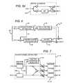
- FIG. 3 ais a block diagram of a front-channel virtualization processing block having HRTF filters with a sum and difference transfer function and the generation of two output signals.
- FIG. 3 bis a block diagram of a surround-channel virtualization processing block having HRTF filters with a sum and difference transfer function and generating two output signals.
- FIG. 4is a schematic diagram illustrating the auditory effect of spatial extension processing according to an embodiment of the invention.
- FIG. 5 ais a block diagram of the spatial extension processing block depicting the center channel signal being filtered by a right all pass filter and a left all pass filter.
- FIG. 5 bis a block diagram of an all pass filter including a delay unit.
- FIG. 5 cis a block diagram of a spatial extension processing block having a delay unit.
- FIG. 5 dis a block diagram of a spatial extension processing block having one all-pass filter.
- FIG. 6is a block diagram of a virtual audio processing apparatus including a center channel extraction block for extracting a center channel signal from right and left channel signals.
- FIG. 7is a block diagram of a center-channel extraction processing block performing sub-band analysis.
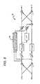
- FIG. 8is a block diagram of a virtual audio processing apparatus having a spatial extension and channel virtualizer in the same processing block.
- Elements of one embodiment of the inventionmay be implemented by hardware, firmware, software or any combination thereof.
- the elements of an embodiment of the present inventionare essentially the code segments to perform the necessary tasks.
- the softwaremay include the actual code to carry out the operations described in one embodiment of the invention, or code that emulates or simulates the operations.
- the program or code segmentscan be stored in a processor or machine accessible medium or transmitted by a computer data signal embodied in a carrier wave, or a signal modulated by a carrier, over a transmission medium.
- the “processor readable or accessible medium” or “machine readable or accessible medium”may include any medium that can store, transmit, or transfer information.
- Examples of the processor readable mediuminclude an electronic circuit, a semiconductor memory device, a read only memory (ROM), a flash memory, an erasable ROM (EROM), a floppy diskette, a compact disk (CD) ROM, an optical disk, a hard disk, a fiber optic medium, a radio frequency (RF) link, etc.
- the computer data signalmay include any signal that can propagate over a transmission medium such as electronic network channels, optical fibers, air, electromagnetic, RF links, etc.
- the code segmentsmay be downloaded via computer networks such as the Internet, Intranet, etc.
- the machine accessible mediummay be embodied in an article of manufacture.
- the machine accessible mediummay include data that, when accessed by a machine, cause the machine to perform the operation described in the following.
- datahere refers to any type of information that is encoded for machine-readable purposes. Therefore, it may include program, code, data, file, etc.
- All or part of an embodiment of the inventionmay be implemented by software.
- the softwaremay have several modules coupled to one another.
- a software moduleis coupled to another module to receive variables, parameters, arguments, pointers, etc. and/or to generate or pass results, updated variables, pointers, etc.
- a software modulemay also be a software driver or interface to interact with the operating system running on the platform.
- a software modulemay also be a hardware driver to configure, set up, initialize, send and receive data to and from a hardware device
- One embodiment of the inventionmay be described as a process which is usually depicted as a flowchart, a flow diagram, a structure diagram, or a block diagram. Although a block diagram may describe the operations as a sequential process, many of the operations can be performed in parallel or concurrently. In addition, the order of the operations may be re-arranged. A process is terminated when its operations are completed. A process may correspond to a method, a program, a procedure, etc.
- FIG. 2is a schematic diagram illustrating an environment in which one embodiment of the invention can be practiced.
- the environmentincludes a virtual audio processing apparatus 26 configured to receive at least one audio source signal 28 .
- the audio source signal 28can be any audio signal such as a mono signal or a two-channel signal (such as a music track or TV broadcast).
- a two-channel audio signalincludes two side channel signals LF(t), RF(t) intended for playback over a pair of frontal loudspeakers LF, RF.
- the audio source signal 28may be a multi-channel signal (such as a movie soundtrack) and include a center channel signal CF(t) and four side channel signals LS(t), LF(t), RF(t), RS(t) intended for playback over a surround-sound loudspeaker array. It is preferred that the audio source signal 28 includes at least a left channel signal LF(t) and a right channel signal RF(t).
- the virtual audio processing apparatus 26processes audio source signals 28 to produce audio output signals 30 a , 30 b for playback over loudspeakers or headphones.
- An audio source signal 28may be a multi-channel signal intended for performance over an array of loudspeakers 14 surrounding the listener, such as the standard ‘5.1’ loudspeaker layout shown on FIG. 1 a , with the loudspeakers labeled LS (Left Surround), LF (Left Front), CF (Center Front), RF (Right Front), RS (Right Surround), SW (Subwoofer).
- the standard ‘5.1’ loudspeaker layout 14is provided by way of example and not limitation.
- audio output signals 30 a , 30 bmay be configured for simulating any source (or ‘virtual’) loudspeaker layout represented as ‘m.n’, where m is the number of main (satellite) channels and n is the number of subwoofer (or Low Frequency Enhancement) channels.
- the audio output signals 30 a , 30 bmay be processed for playback over a pair of headphones 12 .
- the virtual audio processing apparatus 26has various conventional processing means (not shown) which may include a digital signal processor connected to digital audio input and output interfaces and memory storage for the storage of temporary processing data and of processing program instructions.
- processing meansmay include a digital signal processor connected to digital audio input and output interfaces and memory storage for the storage of temporary processing data and of processing program instructions.
- the audio output signals 30 a , 30 bare directed to a pair of loudspeakers respectively labeled L and R.
- FIG. 2depicts the intended placement of the loudspeakers LS, LF, CF, RF, and RS for a five-channel audio input signal.
- the physical spacing of the output loudspeakers L and Ris narrower than the intended spacing of the LF and RF loudspeakers.
- the virtual audio processing apparatus 26is designed to produce a stereo widening effect. The stereo widening effect provides the illusion that the audio signals LF(t) and RF(t) emanate from a virtual pair of loudspeakers located at positions LF and RF.
- a virtual loudspeakermay be positioned at any location on the spatial sound stage.
- audio source signals 28may be processed to emanate from virtual loudspeakers at any perceived position.
- the virtual audio processing apparatus 26produces the perception that audio channel signals CF(t), LS(t) and RS(t) emanate from loudspeakers located respectively at positions CF, LS and RS.
- audio channel signals CF(t), LF(t) and RF(t)may be perceived to emanate from loudspeakers located respectively at positions CF, LF, and RF.
- these illusionsmay be achieved by applying transformations to the audio input signals 28 taking into account measurements or approximations of the loudspeaker-to-ear acoustic transfer functions, or Head Related Transfer Functions (HRTF).
- HRTFHead Related Transfer Functions
- An HRTFrelates to the frequency dependent time and amplitude differences that are imposed on the sound emanating from any sound source and are attributed to acoustic diffraction around the listener's head. It is contemplated that every source from any direction yields two associated HRTFs (one for each ear). It is important to note that most 3-D sound systems are incapable of using the HRTFs of the user; in most cases, nonindividualized (generalized) HRTFs are used. Usually, a theoretical approach, physically or psychoacoustically based, is used for deriving nonindividualized HRTFs that are generalizable to a large segment of the population.
- the ipsilateral HRTFrepresents the path taken to the ear nearest the source and the contralateral HRTF represents the path taken to the farthest ear.
- the HRTFs denoted on FIG. 2are as follow:
- the virtual audio processing apparatusassumes a symmetrical relationship between the physical and virtual loudspeaker layouts with respect to the listener's frontal direction.
- a listeneris positioned on a linear axis in relation to the CF speaker such that the audio image is directionally balanced. It is contemplated that slight changes in head positions will not disjoint the symmetrical relationship.
- a symmetrical relationshipis provided by way of example and not limitation. In this regard, a person skilled in the art will understand that the present invention may extend to asymmetrical virtual loudspeaker layouts including an arbitrary number of virtual loudspeakers positioned at any perceived location on a sound stage.
- the intended output speakersmay be headphones 12 .
- the actual output loudspeakers L and Rare positioned at the ears of the listener.
- the transfer function H 0iis the headphone transfer function and the transfer function H 0c , may be neglected.
- FIG. 3a block diagram of the virtual audio processing apparatus 26 is shown.
- the overall processingis decomposed into three parallel processing blocks processing audio source signal channels 28 , whose outputs signals are summed respectively to compute the final output signal L(t), R(t).
- Each audio source signal 28is virtualized thereby providing the illusion that each source channel signal LF(t), RF(t), LS(t), RS(t), CF(t) is positioned at a different predetermined position in 3D space.
- only one of the side channel signals LF(t), RF(t), LS(t), RS(t)is required to be virtualized.
- the LS(t) and RS(t) channels of the 5.1 surround mixmay be binaurally processed so as to create virtual sources with the HRTF corresponding to approximately 110 degrees from the front on either side (the normal locations of the surround loudspeakers).
- the front-channel virtualization processing block 34processes the front-channel source audio signal pair LF(t), RF(t).
- the surround-channel virtualization processing block 36processes the surround-channel source audio signal pair LS(t), RS(t).
- the center-channel virtualization processing block 38processes the center-channel source audio signal CF(t).
- the center-channel virtualization processing block 38may include a signal attenuation of 3 dB.
- the center-channel virtualization processing block 38may apply a filter to the source signal CF(t), defined by transfer function [H F /H 0i ].
- FIGS. 3 a and 3 ba block diagram depicting a preferred embodiment of the front-channel virtualization processing block 34 and of the surround-channel virtualization processing block 36 is shown.
- the present embodimentassumes symmetry of the physical and virtual loudspeaker layouts with respect to the listener's frontal direction.
- HF SUM[H Fi +H Fc ]/[H 0i +H 0c ]
- HF DIFF[H Fi ⁇ H Fc ]/[H 0i ⁇ H 0c ]
- HS SUM[H Si +H Sc ]/[H 0i +H 0c ]
- HS DIFF[H Si ⁇ H Sc ]/[H 0i ⁇ H 0c ].
- the center-channel virtualization block 38is followed by a spatial extension processing block 40 (or spatial extensor, described in further detail below), producing two distinct (L and R) output signals from a single-channel input signal CF(t), yielding a pseudo-stereo effect.
- a pseudo-stereo effectconverts a mono signal to a two-channel or multi-channel output signal, thereby spreading a mono signal across a two-channel or multi-channel stage.
- the resulting subjective effectis the sense that the center-channel audio signal CF(t) emanates from an extended region of space located in the vicinity of the physical loudspeakers, as illustrated in FIG. 4 .
- the resulting signal CF(t)is thus spread out or dispersed, thereby creating a more natural sound perception.
- the resulting subjective effectis a more natural and externalized perception of the localization of the center-channel audio signal.
- the subjective effectis an improved frontal “out-of-head” perception, thereby mitigating a common drawback in headphone playback.
- the center-channel virtualization processing block 38is a single-input, single-output filter, thus it would be equivalent to modify the process of FIG. 3 by first applying the spatial extension processing to the input signal CF(t), and then applying center-channel virtualization processing identically to each of the two output signals L and R of the spatial extension processing block.
- FIG. 5 aa block diagram of a spatial extension processing block 40 is shown.
- the source signal CF(t)is split into left and right output signals L, R, which are processed by distinct all-pass filters APF L and APF R .
- An all-pass filteris an electronic filter that passes all frequencies equally, but changes the phase relationship between various frequencies. Thus, an all-pass filter may provide a frequency dependent phase shift to a signal and/or vary its propagation delay with frequency. All pass filters are generally used to compensate for other undesired phase shifts that arise in a process, or for mixing with an unshifted version of the original signal to implement a notch comb filter. They may also be used to convert a mixed phase filter into a minimum phase filter with an equivalent magnitude response or an unstable filter into a stable filter with an equivalent magnitude response.
- the all-pass filter APFincludes a delay unit 42 denoted as Z N , for introducing a time delay to the center channel signal CF(t).
- the digital delay length Nis expressed in samples and g denotes a positive or negative loop gain such that its magnitude
- the spatial extension processing block 40it is preferred for the spatial extension processing block 40 to include a different digital delay length N for each all-pass filter APF, with a delay time duration between 3 and 5 ms. However, this range of time duration is not intended to be limiting, as the time duration may be determined according to various parameters.
- the difference between the L and R output signals of the spatial extension processing block 40is produced by adding and subtracting, respectively, to the audio source signal CF(t) a delayed copy of itself. It is preferred that the copied CF(t) signal includes a time delay having a digital delay length between 2 and 4 ms.
- the degree of spatial extensionis determined by the scaling factors a and b. The scaling factors are generated according to the multiplication factor having the ratio a/b. It is preferred that the ratio a/b be comprised within [0.0, 1.0].
- FIG. 5 da block diagram of a spatial extension processing block 40 according to an alternative embodiment of the invention is shown.
- the processing block of FIG. 5 cis modified by replacing the delay unit 42 with an all-pass filter APF.
- a delay or an all-pass filteris applied to CF(t), thereby creating a phase-shifted center channel signal.
- the phase-shifted center channel signalis subtracted from CF(t) producing the right output.
- the phase-shifted center channel signalis added to CF(t) producing the left output.
- Variations of the spatial extension processing block 40may be realized by replacing the APF with another single-input, single-output all-pass network.
- FIG. 6another embodiment of the front-channel and center-channel virtualization processing included in apparatus 26 is shown. This embodiment is preferred when the audio source signal 28 does not include a discrete center-channel signal CF(t).
- a center-channel extraction processing block 44is inserted prior to the front-channel virtualization processing block 34 .
- the center-channel extraction processing block 44receives the front-channel signal pair, denoted LF(t), RF(t), and outputs three signals LF′, RF′ and CF′.
- the audio signal CF′is the extracted center-channel audio signal, which contains the audio signal components that are common to the original left and right input signals LF and RF (or “center-panned”).
- the audio signal LF′contains the audio signal components that are localized (or “panned”) to the left in the original two-channel input signal (LF, RF).
- the audio signal RE′contains the audio signal components that are localized (or “panned”) to the right in the input signal (LF, RF).
- the three signals LE′, RF′ and CF′are then processed in the same manner as in the virtual audio processing apparatus 26 of FIG. 3 .
- the extracted center-channel signal CF′may be combined additively with a discrete center-channel input signal CF(t), so that the same virtual audio processing apparatus 26 may also be employed for processing multi-channel input signals that include an original center-channel signal.
- FIG. 7a block diagram of an embodiment of the center-channel extraction processing block 44 is shown.
- the audio source channel signals LF(t) and RF(t)are processed by optional sub-band analysis stages 46 a , 46 b which decompose the signals into a plurality of sub-band audio signals associated to different frequency bands.
- the center-channel extraction processis performed separately for each frequency band, and a synthesis block may optionally be provided for recombining the sub-band output signals corresponding to each of the three output channels LF(t), RF(t) and CF(t) into the full-band audio signals LE′, RF′ and CF′.
- the scaling coefficients k L , k R and k Care adaptively computed by an adaptive dominance detector block 48 which continuously evaluates the degree of inter-channel similarity M between the input channels, raises the value of k C when the inter-channel similarity is high, and reduces the value of k C when the inter-channel similarity is low. Concurrently, the adaptive dominance detector block reduces the values of k L and k R when the inter-channel similarity is high and increases these values when the inter-channel similarity is low.
- FIG. 8a block diagram of virtual audio processing apparatus 26 according to an alternative embodiment is shown.
- the spatial extension processing block 40 and the front-channel virtualization processing block 34 of FIG. 3 aare combined in a single processing block.
- the spatial extension processingis applied to the output of the filter HF SUM , which is derived from the sum of the audio source channel signals LF(t) and RF(t).
- a delay or an all-pass filteris applied to CF(t), thereby creating a phase-shifted center channel signal.
- the phase-shifted center channel signalis subtracted from CF(t) producing the right output.
- the phase-shifted center channel signalis added to CF(t) producing the left output.
- the difference of the right and left side channel signalsare processed by HF (DIFF) to produce a filtered difference signal.
- the filtered difference signalis summed with the phase-shifted center channel signal.
- the optional adaptive dominance detector 48continually adjusts the degree of spatial extension according to the inter-channel similarity index M.
- the input signals LF(t) and RF(t)may be pre-processed by a sub-band analysis block (not shown in FIG. 8 ) and the output signals L and R may be post processed by a synthesis block to recombine sub-band signals into full-band signals.
Landscapes
- Physics & Mathematics (AREA)
- Engineering & Computer Science (AREA)
- Acoustics & Sound (AREA)
- Signal Processing (AREA)
- Stereophonic System (AREA)
Abstract
Description
- H0i: ipsilateral HRTF for the front left or right physical loudspeaker locations;
- H0c: contralateral HRTF for the front left or right physical loudspeaker locations;
- HFi: ipsilateral HRTF for the front left or right virtual loudspeaker locations;
- HFc: contralateral HRTF for the front left or right virtual loudspeaker locations;
- HSi: ipsilateral HRTF for the surround left or right virtual loudspeaker locations;
- HSc: contralateral HRTF for the surround left or right virtual loudspeaker locations;
- HF: HRTF for front center virtual loudspeaker location (identical for the two ears);
HFSUM=[HFi+HFc]/[H0i+H0c];
HFDIFF=[HFi−HFc]/[H0i−H0c];
HSSUM=[HSi+HSc]/[H0i+H0c];
HSDIFF=[HSi−HSc]/[H0i−H0c].
LF′=kL*LF; RF′=kR*RF; CF′=kC*(LF+RF);
M=log [|LF+RF|2/|LF−RF|2]
Claims (10)
a2+b2=c;
H(SUM)=[Hi+Hc]/[H0i+H0c];
H(DIFF)=[Hi−Hc]/[H0i−H0c];
Priority Applications (11)
| Application Number | Priority Date | Filing Date | Title |
|---|---|---|---|
| US12/762,915US8000485B2 (en) | 2009-06-01 | 2010-04-19 | Virtual audio processing for loudspeaker or headphone playback |
| TW099115935ATWI489887B (en) | 2009-06-01 | 2010-05-19 | Virtual audio processing for loudspeaker or headphone playback |
| HK13100483.9AHK1173250B (en) | 2009-06-01 | 2010-05-28 | Virtual audio processing for loudspeaker or headphone playback |
| EP10783869.0AEP2438530B1 (en) | 2009-06-01 | 2010-05-28 | Virtual audio processing for loudspeaker or headphone playback |
| CN201080028926.1ACN102597987B (en) | 2009-06-01 | 2010-05-28 | Virtual audio processing for loudspeaker or headphone playback |
| JP2012514020AJP5746156B2 (en) | 2009-06-01 | 2010-05-28 | Virtual audio processing for speaker or headphone playback |
| PCT/US2010/036683WO2010141371A1 (en) | 2009-06-01 | 2010-05-28 | Virtual audio processing for loudspeaker or headphone playback |
| BRPI1011868ABRPI1011868A2 (en) | 2009-06-01 | 2010-05-28 | method for processing audio signals, and, audio signal processing apparatus |
| KR1020117028717AKR101639099B1 (en) | 2009-06-01 | 2010-05-28 | Virtual audio processing for loudspeaker or headphone playback |
| CA2763160ACA2763160C (en) | 2009-06-01 | 2010-05-28 | Virtual audio processing for loudspeaker or headphone playback |
| SG2011088069ASG176280A1 (en) | 2009-06-01 | 2010-05-28 | Virtual audio processing for loudspeaker or headphone playback |
Applications Claiming Priority (2)
| Application Number | Priority Date | Filing Date | Title |
|---|---|---|---|
| US21756209P | 2009-06-01 | 2009-06-01 | |
| US12/762,915US8000485B2 (en) | 2009-06-01 | 2010-04-19 | Virtual audio processing for loudspeaker or headphone playback |
Publications (2)
| Publication Number | Publication Date |
|---|---|
| US20100303246A1 US20100303246A1 (en) | 2010-12-02 |
| US8000485B2true US8000485B2 (en) | 2011-08-16 |
Family
ID=43220244
Family Applications (1)
| Application Number | Title | Priority Date | Filing Date |
|---|---|---|---|
| US12/762,915Expired - Fee RelatedUS8000485B2 (en) | 2009-06-01 | 2010-04-19 | Virtual audio processing for loudspeaker or headphone playback |
Country Status (10)
| Country | Link |
|---|---|
| US (1) | US8000485B2 (en) |
| EP (1) | EP2438530B1 (en) |
| JP (1) | JP5746156B2 (en) |
| KR (1) | KR101639099B1 (en) |
| CN (1) | CN102597987B (en) |
| BR (1) | BRPI1011868A2 (en) |
| CA (1) | CA2763160C (en) |
| SG (1) | SG176280A1 (en) |
| TW (1) | TWI489887B (en) |
| WO (1) | WO2010141371A1 (en) |
Cited By (10)
| Publication number | Priority date | Publication date | Assignee | Title |
|---|---|---|---|---|
| US9264838B2 (en) | 2012-12-27 | 2016-02-16 | Dts, Inc. | System and method for variable decorrelation of audio signals |
| RU2648588C2 (en)* | 2013-10-22 | 2018-03-26 | Фраунхофер-Гезелльшафт Цур Фердерунг Дер Ангевандтен Форшунг Е.Ф. | Method for decoding and encoding a downmix matrix, method for presenting audio content, encoder and decoder for a downmix matrix, audio encoder and audiodecoder |
| US10616705B2 (en) | 2017-10-17 | 2020-04-07 | Magic Leap, Inc. | Mixed reality spatial audio |
| US10728683B2 (en) | 2017-09-01 | 2020-07-28 | Dts, Inc. | Sweet spot adaptation for virtualized audio |
| US10779082B2 (en) | 2018-05-30 | 2020-09-15 | Magic Leap, Inc. | Index scheming for filter parameters |
| US10979844B2 (en) | 2017-03-08 | 2021-04-13 | Dts, Inc. | Distributed audio virtualization systems |
| US11304017B2 (en) | 2019-10-25 | 2022-04-12 | Magic Leap, Inc. | Reverberation fingerprint estimation |
| US11304020B2 (en) | 2016-05-06 | 2022-04-12 | Dts, Inc. | Immersive audio reproduction systems |
| US11800174B2 (en) | 2018-02-15 | 2023-10-24 | Magic Leap, Inc. | Mixed reality virtual reverberation |
| US12165657B2 (en) | 2019-08-30 | 2024-12-10 | Dolby Laboratories Licensing Corporation | Channel identification of multi-channel audio signals |
Families Citing this family (28)
| Publication number | Priority date | Publication date | Assignee | Title |
|---|---|---|---|---|
| WO2013122385A1 (en) | 2012-02-15 | 2013-08-22 | Samsung Electronics Co., Ltd. | Data transmitting apparatus, data receiving apparatus, data transreceiving system, data transmitting method, data receiving method and data transreceiving method |
| WO2013122386A1 (en) | 2012-02-15 | 2013-08-22 | Samsung Electronics Co., Ltd. | Data transmitting apparatus, data receiving apparatus, data transreceiving system, data transmitting method, data receiving method and data transreceiving method |
| WO2013122387A1 (en) | 2012-02-15 | 2013-08-22 | Samsung Electronics Co., Ltd. | Data transmitting apparatus, data receiving apparatus, data transceiving system, data transmitting method, and data receiving method |
| US9510124B2 (en)* | 2012-03-14 | 2016-11-29 | Harman International Industries, Incorporated | Parametric binaural headphone rendering |
| WO2014190140A1 (en)* | 2013-05-23 | 2014-11-27 | Alan Kraemer | Headphone audio enhancement system |
| DE202014010599U1 (en)* | 2014-01-05 | 2016-02-02 | Kronoton Gmbh | Device with speakers |
| CN113038355B (en)* | 2014-03-24 | 2022-12-16 | 三星电子株式会社 | Method and apparatus for rendering an acoustic signal, and computer-readable recording medium |
| US10089785B2 (en) | 2014-07-25 | 2018-10-02 | mindHIVE Inc. | Real-time immersive mediated reality experiences |
| CN106688252B (en)* | 2014-09-12 | 2020-01-03 | 索尼半导体解决方案公司 | Audio processing apparatus and method |
| CN104284271B (en)* | 2014-09-18 | 2018-05-15 | 国光电器股份有限公司 | A kind of surround sound Enhancement Method for loudspeaker array |
| WO2016077317A1 (en)* | 2014-11-11 | 2016-05-19 | Google Inc. | Virtual sound systems and methods |
| RU2673390C1 (en)* | 2014-12-12 | 2018-11-26 | Хуавэй Текнолоджиз Ко., Лтд. | Signal processing device for amplifying speech component in multi-channel audio signal |
| CN105142094B (en)* | 2015-09-16 | 2018-07-13 | 华为技术有限公司 | A kind for the treatment of method and apparatus of audio signal |
| US10397730B2 (en) | 2016-02-03 | 2019-08-27 | Global Delight Technologies Pvt. Ltd. | Methods and systems for providing virtual surround sound on headphones |
| CN109417677B (en) | 2016-06-21 | 2021-03-05 | 杜比实验室特许公司 | Head tracking for pre-rendered binaural audio |
| CN108156561B (en)* | 2017-12-26 | 2020-08-04 | 广州酷狗计算机科技有限公司 | Audio signal processing method and device and terminal |
| US10764704B2 (en)* | 2018-03-22 | 2020-09-01 | Boomcloud 360, Inc. | Multi-channel subband spatial processing for loudspeakers |
| WO2019241760A1 (en) | 2018-06-14 | 2019-12-19 | Magic Leap, Inc. | Methods and systems for audio signal filtering |
| KR102531634B1 (en)* | 2018-08-10 | 2023-05-11 | 삼성전자주식회사 | Audio apparatus and method of controlling the same |
| CN110856095B (en)* | 2018-08-20 | 2021-11-19 | 华为技术有限公司 | Audio processing method and device |
| FR3091636B1 (en) | 2019-01-04 | 2020-12-11 | Parrot Faurecia Automotive Sas | Multichannel audio signal processing method |
| CN114584914B (en)* | 2020-11-30 | 2025-01-14 | 深圳市三诺数字科技有限公司 | A 3D sound effect method and device |
| US11445320B1 (en)* | 2021-06-28 | 2022-09-13 | Sennheiser Electronic Gmbh & Co. Kg | Device for processing multi-channel audio signals, method for processing multi-channel audio signals, and computer-readable storage medium |
| KR20250052461A (en) | 2021-07-08 | 2025-04-18 | 붐클라우드 360 인코포레이티드 | Colorless generation of elevation perceptual cues using all-pass filter networks |
| EP4378178A1 (en)* | 2021-07-28 | 2024-06-05 | Dolby Laboratories Licensing Corporation | A method of processing audio for playback of immersive audio |
| EP4454297A1 (en)* | 2021-12-20 | 2024-10-30 | Dolby Laboratories Licensing Corporation | A method of processing audio for playback of immersive audio |
| TWI857414B (en)* | 2022-12-08 | 2024-10-01 | 瑞昱半導體股份有限公司 | Signal processing method and player device utilizing the same |
| CN118264971B (en)* | 2024-05-31 | 2024-09-27 | 苏州灵境影音技术有限公司 | Speaker-based spatial audio system, audio processor, vehicle, virtual surround sound conversion method, and audio rendering method |
Citations (14)
| Publication number | Priority date | Publication date | Assignee | Title |
|---|---|---|---|---|
| US5426702A (en)* | 1992-10-15 | 1995-06-20 | U.S. Philips Corporation | System for deriving a center channel signal from an adapted weighted combination of the left and right channels in a stereophonic audio signal |
| US20040005066A1 (en) | 1998-10-13 | 2004-01-08 | Kraemer Alan D. | Apparatus and method for synthesizing pseudo-stereophonic outputs from a monophonic input |
| US6928169B1 (en) | 1998-12-24 | 2005-08-09 | Bose Corporation | Audio signal processing |
| US20070147623A1 (en)* | 2005-12-22 | 2007-06-28 | Samsung Electronics Co., Ltd. | Apparatus to generate multi-channel audio signals and method thereof |
| US20070154019A1 (en)* | 2005-12-22 | 2007-07-05 | Samsung Electronics Co., Ltd. | Apparatus and method of reproducing virtual sound of two channels based on listener's position |
| US20070297519A1 (en) | 2004-10-28 | 2007-12-27 | Jeffrey Thompson | Audio Spatial Environment Engine |
| US20080031462A1 (en) | 2006-08-07 | 2008-02-07 | Creative Technology Ltd | Spatial audio enhancement processing method and apparatus |
| US20080037796A1 (en) | 2006-08-08 | 2008-02-14 | Creative Technology Ltd | 3d audio renderer |
| US20080056503A1 (en) | 2004-10-14 | 2008-03-06 | Dolby Laboratories Licensing Corporation | Head Related Transfer Functions for Panned Stereo Audio Content |
| US20080126086A1 (en) | 2005-04-01 | 2008-05-29 | Qualcomm Incorporated | Systems, methods, and apparatus for gain coding |
| US20090092259A1 (en) | 2006-05-17 | 2009-04-09 | Creative Technology Ltd | Phase-Amplitude 3-D Stereo Encoder and Decoder |
| US20090252356A1 (en) | 2006-05-17 | 2009-10-08 | Creative Technology Ltd | Spatial audio analysis and synthesis for binaural reproduction and format conversion |
| US20090304189A1 (en) | 2006-03-13 | 2009-12-10 | Dolby Laboratorie Licensing Corporation | Rendering Center Channel Audio |
| US20100119081A1 (en) | 2002-12-03 | 2010-05-13 | Aylward J Richard | Electroacoustical transducing with low frequency augmenting devices |
Family Cites Families (6)
| Publication number | Priority date | Publication date | Assignee | Title |
|---|---|---|---|---|
| US6442277B1 (en)* | 1998-12-22 | 2002-08-27 | Texas Instruments Incorporated | Method and apparatus for loudspeaker presentation for positional 3D sound |
| US7949141B2 (en)* | 2003-11-12 | 2011-05-24 | Dolby Laboratories Licensing Corporation | Processing audio signals with head related transfer function filters and a reverberator |
| WO2005054202A1 (en) | 2003-11-25 | 2005-06-16 | Eli Lilly And Company | 7-phenyl-isoquinoline-5-sulfonylamino derivatives as inhibitors of akt (proteinkinase b) |
| BRPI0509113B8 (en)* | 2004-04-05 | 2018-10-30 | Koninklijke Philips Nv | multichannel encoder, method for encoding input signals, encoded data content, data bearer, and operable decoder for decoding encoded output data |
| JP4335752B2 (en) | 2004-06-15 | 2009-09-30 | 三菱電機株式会社 | Pseudo stereo signal generation apparatus and pseudo stereo signal generation program |
| JP4792086B2 (en) | 2005-12-20 | 2011-10-12 | フラウンホッファー−ゲゼルシャフト ツァ フェルダールング デァ アンゲヴァンテン フォアシュンク エー.ファオ | Apparatus and method for synthesizing three output channels using two input channels |
- 2010
- 2010-04-19USUS12/762,915patent/US8000485B2/ennot_activeExpired - Fee Related
- 2010-05-19TWTW099115935Apatent/TWI489887B/ennot_activeIP Right Cessation
- 2010-05-28KRKR1020117028717Apatent/KR101639099B1/ennot_activeExpired - Fee Related
- 2010-05-28EPEP10783869.0Apatent/EP2438530B1/ennot_activeNot-in-force
- 2010-05-28CNCN201080028926.1Apatent/CN102597987B/ennot_activeExpired - Fee Related
- 2010-05-28JPJP2012514020Apatent/JP5746156B2/ennot_activeExpired - Fee Related
- 2010-05-28SGSG2011088069Apatent/SG176280A1/enunknown
- 2010-05-28BRBRPI1011868Apatent/BRPI1011868A2/ennot_activeIP Right Cessation
- 2010-05-28WOPCT/US2010/036683patent/WO2010141371A1/enactiveApplication Filing
- 2010-05-28CACA2763160Apatent/CA2763160C/ennot_activeExpired - Fee Related
Patent Citations (14)
| Publication number | Priority date | Publication date | Assignee | Title |
|---|---|---|---|---|
| US5426702A (en)* | 1992-10-15 | 1995-06-20 | U.S. Philips Corporation | System for deriving a center channel signal from an adapted weighted combination of the left and right channels in a stereophonic audio signal |
| US20040005066A1 (en) | 1998-10-13 | 2004-01-08 | Kraemer Alan D. | Apparatus and method for synthesizing pseudo-stereophonic outputs from a monophonic input |
| US6928169B1 (en) | 1998-12-24 | 2005-08-09 | Bose Corporation | Audio signal processing |
| US20100119081A1 (en) | 2002-12-03 | 2010-05-13 | Aylward J Richard | Electroacoustical transducing with low frequency augmenting devices |
| US20080056503A1 (en) | 2004-10-14 | 2008-03-06 | Dolby Laboratories Licensing Corporation | Head Related Transfer Functions for Panned Stereo Audio Content |
| US20070297519A1 (en) | 2004-10-28 | 2007-12-27 | Jeffrey Thompson | Audio Spatial Environment Engine |
| US20080126086A1 (en) | 2005-04-01 | 2008-05-29 | Qualcomm Incorporated | Systems, methods, and apparatus for gain coding |
| US20070147623A1 (en)* | 2005-12-22 | 2007-06-28 | Samsung Electronics Co., Ltd. | Apparatus to generate multi-channel audio signals and method thereof |
| US20070154019A1 (en)* | 2005-12-22 | 2007-07-05 | Samsung Electronics Co., Ltd. | Apparatus and method of reproducing virtual sound of two channels based on listener's position |
| US20090304189A1 (en) | 2006-03-13 | 2009-12-10 | Dolby Laboratorie Licensing Corporation | Rendering Center Channel Audio |
| US20090092259A1 (en) | 2006-05-17 | 2009-04-09 | Creative Technology Ltd | Phase-Amplitude 3-D Stereo Encoder and Decoder |
| US20090252356A1 (en) | 2006-05-17 | 2009-10-08 | Creative Technology Ltd | Spatial audio analysis and synthesis for binaural reproduction and format conversion |
| US20080031462A1 (en) | 2006-08-07 | 2008-02-07 | Creative Technology Ltd | Spatial audio enhancement processing method and apparatus |
| US20080037796A1 (en) | 2006-08-08 | 2008-02-14 | Creative Technology Ltd | 3d audio renderer |
Non-Patent Citations (2)
| Title |
|---|
| AES Convention Paper "Center-Channel Processing In Virtual 3-D Audio Reproduction over Headphones or Loudspeakers." Presented at the 128th Convention, May 22-25, 2010, London UK. |
| International Search Report and Written Opinion issued in Corresponding International Application No. PCT/US2010/036683. |
Cited By (25)
| Publication number | Priority date | Publication date | Assignee | Title |
|---|---|---|---|---|
| US9264838B2 (en) | 2012-12-27 | 2016-02-16 | Dts, Inc. | System and method for variable decorrelation of audio signals |
| US11922957B2 (en) | 2013-10-22 | 2024-03-05 | Fraunhofer-Gesellschaft zur Förderung der angewandten Forschung e.V. | Method for decoding and encoding a downmix matrix, method for presenting audio content, encoder and decoder for a downmix matrix, audio encoder and audio decoder |
| US9947326B2 (en) | 2013-10-22 | 2018-04-17 | Fraunhofer-Gesellschaft zur Föderung der angewandten Forschung e.V. | Method for decoding and encoding a downmix matrix, method for presenting audio content, encoder and decoder for a downmix matrix, audio encoder and audio decoder |
| US10468038B2 (en) | 2013-10-22 | 2019-11-05 | Fraunhofer-Gesellschaft zur Förderung der angewandten Forschung e.V. | Method for decoding and encoding a downmix matrix, method for presenting audio content, encoder and decoder for a downmix matrix, audio encoder and audio decoder |
| US12412586B2 (en) | 2013-10-22 | 2025-09-09 | Fraunhofer-Gesellschaft Zur Foerderung Der Angewandten Forschung E.V. | Method for decoding and encoding a downmix matrix, method for presenting audio content, encoder and decoder for a downmix matrix, audio encoder and audio decoder |
| RU2648588C2 (en)* | 2013-10-22 | 2018-03-26 | Фраунхофер-Гезелльшафт Цур Фердерунг Дер Ангевандтен Форшунг Е.Ф. | Method for decoding and encoding a downmix matrix, method for presenting audio content, encoder and decoder for a downmix matrix, audio encoder and audiodecoder |
| US11393481B2 (en) | 2013-10-22 | 2022-07-19 | Fraunhofer-Gesellschaft Zur Foerderung Der Angewandten Forschung E.V. | Method for decoding and encoding a downmix matrix, method for presenting audio content, encoder and decoder for a downmix matrix, audio encoder and audio decoder |
| US11304020B2 (en) | 2016-05-06 | 2022-04-12 | Dts, Inc. | Immersive audio reproduction systems |
| US10979844B2 (en) | 2017-03-08 | 2021-04-13 | Dts, Inc. | Distributed audio virtualization systems |
| US10728683B2 (en) | 2017-09-01 | 2020-07-28 | Dts, Inc. | Sweet spot adaptation for virtualized audio |
| US10863301B2 (en) | 2017-10-17 | 2020-12-08 | Magic Leap, Inc. | Mixed reality spatial audio |
| US11895483B2 (en) | 2017-10-17 | 2024-02-06 | Magic Leap, Inc. | Mixed reality spatial audio |
| US10616705B2 (en) | 2017-10-17 | 2020-04-07 | Magic Leap, Inc. | Mixed reality spatial audio |
| US12317064B2 (en) | 2017-10-17 | 2025-05-27 | Magic Leap, Inc. | Mixed reality spatial audio |
| US11800174B2 (en) | 2018-02-15 | 2023-10-24 | Magic Leap, Inc. | Mixed reality virtual reverberation |
| US12143660B2 (en) | 2018-02-15 | 2024-11-12 | Magic Leap, Inc. | Mixed reality virtual reverberation |
| US11012778B2 (en) | 2018-05-30 | 2021-05-18 | Magic Leap, Inc. | Index scheming for filter parameters |
| US11678117B2 (en) | 2018-05-30 | 2023-06-13 | Magic Leap, Inc. | Index scheming for filter parameters |
| US10779082B2 (en) | 2018-05-30 | 2020-09-15 | Magic Leap, Inc. | Index scheming for filter parameters |
| US12267654B2 (en) | 2018-05-30 | 2025-04-01 | Magic Leap, Inc. | Index scheming for filter parameters |
| US12165657B2 (en) | 2019-08-30 | 2024-12-10 | Dolby Laboratories Licensing Corporation | Channel identification of multi-channel audio signals |
| US11540072B2 (en) | 2019-10-25 | 2022-12-27 | Magic Leap, Inc. | Reverberation fingerprint estimation |
| US12149896B2 (en) | 2019-10-25 | 2024-11-19 | Magic Leap, Inc. | Reverberation fingerprint estimation |
| US11304017B2 (en) | 2019-10-25 | 2022-04-12 | Magic Leap, Inc. | Reverberation fingerprint estimation |
| US11778398B2 (en) | 2019-10-25 | 2023-10-03 | Magic Leap, Inc. | Reverberation fingerprint estimation |
Also Published As
| Publication number | Publication date |
|---|---|
| CA2763160A1 (en) | 2010-12-09 |
| EP2438530B1 (en) | 2018-04-04 |
| KR101639099B1 (en) | 2016-07-12 |
| CA2763160C (en) | 2016-02-23 |
| EP2438530A1 (en) | 2012-04-11 |
| KR20120036303A (en) | 2012-04-17 |
| WO2010141371A1 (en) | 2010-12-09 |
| JP2012529228A (en) | 2012-11-15 |
| EP2438530A4 (en) | 2016-12-07 |
| CN102597987A (en) | 2012-07-18 |
| TW201119420A (en) | 2011-06-01 |
| HK1173250A1 (en) | 2013-05-10 |
| US20100303246A1 (en) | 2010-12-02 |
| CN102597987B (en) | 2015-06-17 |
| SG176280A1 (en) | 2012-01-30 |
| TWI489887B (en) | 2015-06-21 |
| BRPI1011868A2 (en) | 2017-05-16 |
| JP5746156B2 (en) | 2015-07-08 |
Similar Documents
| Publication | Publication Date | Title |
|---|---|---|
| US8000485B2 (en) | Virtual audio processing for loudspeaker or headphone playback | |
| US10299056B2 (en) | Spatial audio enhancement processing method and apparatus | |
| US9706327B2 (en) | Audio decoder configured to convert audio input channels for headphone listening | |
| EP3613219B1 (en) | Stereo virtual bass enhancement | |
| US20050089181A1 (en) | Multi-channel audio surround sound from front located loudspeakers | |
| US5844993A (en) | Surround signal processing apparatus | |
| US7599498B2 (en) | Apparatus and method for producing 3D sound | |
| US8027494B2 (en) | Acoustic image creation system and program therefor | |
| US20220139403A1 (en) | Audio System Height Channel Up-Mixing | |
| WO2024081957A1 (en) | Binaural externalization processing | |
| US20240056735A1 (en) | Stereo headphone psychoacoustic sound localization system and method for reconstructing stereo psychoacoustic sound signals using same | |
| US7065218B2 (en) | Method of generating a left modified and a right modified audio signal for a stereo system | |
| WO2020045109A1 (en) | Signal processing device, signal processing method, and program | |
| CN114363793B (en) | System and method for converting double-channel audio into virtual surrounding 5.1-channel audio | |
| HK1173250B (en) | Virtual audio processing for loudspeaker or headphone playback | |
| Jot et al. | Center-Channel Processing in Virtual 3-D Audio Reproduction over Headphones or Loudspeakers | |
| WO2024206404A2 (en) | Methods, devices, and systems for reproducing spatial audio using binaural externalization processing extensions | |
| GB2609667A (en) | Audio rendering | |
| CN115278506A (en) | Audio processing method and audio processing device |
Legal Events
| Date | Code | Title | Description |
|---|---|---|---|
| AS | Assignment | Owner name:DTS, INC., CALIFORNIA Free format text:ASSIGNMENT OF ASSIGNORS INTEREST;ASSIGNORS:WALSH, MARTIN, MR.;SMITH, WILLIAM PAUL, MR.;JOT, JEAN-MARC, MR.;SIGNING DATES FROM 20100302 TO 20100317;REEL/FRAME:024255/0095 | |
| STCF | Information on status: patent grant | Free format text:PATENTED CASE | |
| FPAY | Fee payment | Year of fee payment:4 | |
| AS | Assignment | Owner name:WELLS FARGO BANK, NATIONAL ASSOCIATION, AS ADMINIS Free format text:SECURITY INTEREST;ASSIGNOR:DTS, INC.;REEL/FRAME:037032/0109 Effective date:20151001 | |
| AS | Assignment | Owner name:ROYAL BANK OF CANADA, AS COLLATERAL AGENT, CANADA Free format text:SECURITY INTEREST;ASSIGNORS:INVENSAS CORPORATION;TESSERA, INC.;TESSERA ADVANCED TECHNOLOGIES, INC.;AND OTHERS;REEL/FRAME:040797/0001 Effective date:20161201 | |
| AS | Assignment | Owner name:DTS, INC., CALIFORNIA Free format text:RELEASE BY SECURED PARTY;ASSIGNOR:WELLS FARGO BANK, NATIONAL ASSOCIATION;REEL/FRAME:040821/0083 Effective date:20161201 | |
| FEPP | Fee payment procedure | Free format text:MAINTENANCE FEE REMINDER MAILED (ORIGINAL EVENT CODE: REM.); ENTITY STATUS OF PATENT OWNER: LARGE ENTITY | |
| LAPS | Lapse for failure to pay maintenance fees | Free format text:PATENT EXPIRED FOR FAILURE TO PAY MAINTENANCE FEES (ORIGINAL EVENT CODE: EXP.); ENTITY STATUS OF PATENT OWNER: LARGE ENTITY | |
| STCH | Information on status: patent discontinuation | Free format text:PATENT EXPIRED DUE TO NONPAYMENT OF MAINTENANCE FEES UNDER 37 CFR 1.362 | |
| FP | Lapsed due to failure to pay maintenance fee | Effective date:20190816 | |
| AS | Assignment | Owner name:INVENSAS BONDING TECHNOLOGIES, INC. (F/K/A ZIPTRONIX, INC.), CALIFORNIA Free format text:RELEASE BY SECURED PARTY;ASSIGNOR:ROYAL BANK OF CANADA;REEL/FRAME:052920/0001 Effective date:20200601 Owner name:TESSERA ADVANCED TECHNOLOGIES, INC, CALIFORNIA Free format text:RELEASE BY SECURED PARTY;ASSIGNOR:ROYAL BANK OF CANADA;REEL/FRAME:052920/0001 Effective date:20200601 Owner name:INVENSAS CORPORATION, CALIFORNIA Free format text:RELEASE BY SECURED PARTY;ASSIGNOR:ROYAL BANK OF CANADA;REEL/FRAME:052920/0001 Effective date:20200601 Owner name:DTS LLC, CALIFORNIA Free format text:RELEASE BY SECURED PARTY;ASSIGNOR:ROYAL BANK OF CANADA;REEL/FRAME:052920/0001 Effective date:20200601 Owner name:IBIQUITY DIGITAL CORPORATION, MARYLAND Free format text:RELEASE BY SECURED PARTY;ASSIGNOR:ROYAL BANK OF CANADA;REEL/FRAME:052920/0001 Effective date:20200601 Owner name:FOTONATION CORPORATION (F/K/A DIGITALOPTICS CORPORATION AND F/K/A DIGITALOPTICS CORPORATION MEMS), CALIFORNIA Free format text:RELEASE BY SECURED PARTY;ASSIGNOR:ROYAL BANK OF CANADA;REEL/FRAME:052920/0001 Effective date:20200601 Owner name:PHORUS, INC., CALIFORNIA Free format text:RELEASE BY SECURED PARTY;ASSIGNOR:ROYAL BANK OF CANADA;REEL/FRAME:052920/0001 Effective date:20200601 Owner name:TESSERA, INC., CALIFORNIA Free format text:RELEASE BY SECURED PARTY;ASSIGNOR:ROYAL BANK OF CANADA;REEL/FRAME:052920/0001 Effective date:20200601 Owner name:DTS, INC., CALIFORNIA Free format text:RELEASE BY SECURED PARTY;ASSIGNOR:ROYAL BANK OF CANADA;REEL/FRAME:052920/0001 Effective date:20200601 |