US7998604B2 - Article having composite layer - Google Patents
Article having composite layerDownload PDFInfo
- Publication number
- US7998604B2 US7998604B2US11/946,100US94610007AUS7998604B2US 7998604 B2US7998604 B2US 7998604B2US 94610007 AUS94610007 AUS 94610007AUS 7998604 B2US7998604 B2US 7998604B2
- Authority
- US
- United States
- Prior art keywords
- ceramic phase
- composite article
- recited
- oxide
- phase
- Prior art date
- Legal status (The legal status is an assumption and is not a legal conclusion. Google has not performed a legal analysis and makes no representation as to the accuracy of the status listed.)
- Active, expires
Links
Images


Classifications
- C—CHEMISTRY; METALLURGY
- C23—COATING METALLIC MATERIAL; COATING MATERIAL WITH METALLIC MATERIAL; CHEMICAL SURFACE TREATMENT; DIFFUSION TREATMENT OF METALLIC MATERIAL; COATING BY VACUUM EVAPORATION, BY SPUTTERING, BY ION IMPLANTATION OR BY CHEMICAL VAPOUR DEPOSITION, IN GENERAL; INHIBITING CORROSION OF METALLIC MATERIAL OR INCRUSTATION IN GENERAL
- C23C—COATING METALLIC MATERIAL; COATING MATERIAL WITH METALLIC MATERIAL; SURFACE TREATMENT OF METALLIC MATERIAL BY DIFFUSION INTO THE SURFACE, BY CHEMICAL CONVERSION OR SUBSTITUTION; COATING BY VACUUM EVAPORATION, BY SPUTTERING, BY ION IMPLANTATION OR BY CHEMICAL VAPOUR DEPOSITION, IN GENERAL
- C23C4/00—Coating by spraying the coating material in the molten state, e.g. by flame, plasma or electric discharge
- C23C4/04—Coating by spraying the coating material in the molten state, e.g. by flame, plasma or electric discharge characterised by the coating material
- C23C4/06—Metallic material
- C—CHEMISTRY; METALLURGY
- C23—COATING METALLIC MATERIAL; COATING MATERIAL WITH METALLIC MATERIAL; CHEMICAL SURFACE TREATMENT; DIFFUSION TREATMENT OF METALLIC MATERIAL; COATING BY VACUUM EVAPORATION, BY SPUTTERING, BY ION IMPLANTATION OR BY CHEMICAL VAPOUR DEPOSITION, IN GENERAL; INHIBITING CORROSION OF METALLIC MATERIAL OR INCRUSTATION IN GENERAL
- C23C—COATING METALLIC MATERIAL; COATING MATERIAL WITH METALLIC MATERIAL; SURFACE TREATMENT OF METALLIC MATERIAL BY DIFFUSION INTO THE SURFACE, BY CHEMICAL CONVERSION OR SUBSTITUTION; COATING BY VACUUM EVAPORATION, BY SPUTTERING, BY ION IMPLANTATION OR BY CHEMICAL VAPOUR DEPOSITION, IN GENERAL
- C23C30/00—Coating with metallic material characterised only by the composition of the metallic material, i.e. not characterised by the coating process
- C—CHEMISTRY; METALLURGY
- C23—COATING METALLIC MATERIAL; COATING MATERIAL WITH METALLIC MATERIAL; CHEMICAL SURFACE TREATMENT; DIFFUSION TREATMENT OF METALLIC MATERIAL; COATING BY VACUUM EVAPORATION, BY SPUTTERING, BY ION IMPLANTATION OR BY CHEMICAL VAPOUR DEPOSITION, IN GENERAL; INHIBITING CORROSION OF METALLIC MATERIAL OR INCRUSTATION IN GENERAL
- C23C—COATING METALLIC MATERIAL; COATING MATERIAL WITH METALLIC MATERIAL; SURFACE TREATMENT OF METALLIC MATERIAL BY DIFFUSION INTO THE SURFACE, BY CHEMICAL CONVERSION OR SUBSTITUTION; COATING BY VACUUM EVAPORATION, BY SPUTTERING, BY ION IMPLANTATION OR BY CHEMICAL VAPOUR DEPOSITION, IN GENERAL
- C23C4/00—Coating by spraying the coating material in the molten state, e.g. by flame, plasma or electric discharge
- C23C4/12—Coating by spraying the coating material in the molten state, e.g. by flame, plasma or electric discharge characterised by the method of spraying
- C23C4/123—Spraying molten metal
- Y—GENERAL TAGGING OF NEW TECHNOLOGICAL DEVELOPMENTS; GENERAL TAGGING OF CROSS-SECTIONAL TECHNOLOGIES SPANNING OVER SEVERAL SECTIONS OF THE IPC; TECHNICAL SUBJECTS COVERED BY FORMER USPC CROSS-REFERENCE ART COLLECTIONS [XRACs] AND DIGESTS
- Y02—TECHNOLOGIES OR APPLICATIONS FOR MITIGATION OR ADAPTATION AGAINST CLIMATE CHANGE
- Y02T—CLIMATE CHANGE MITIGATION TECHNOLOGIES RELATED TO TRANSPORTATION
- Y02T50/00—Aeronautics or air transport
- Y02T50/60—Efficient propulsion technologies, e.g. for aircraft
- Y—GENERAL TAGGING OF NEW TECHNOLOGICAL DEVELOPMENTS; GENERAL TAGGING OF CROSS-SECTIONAL TECHNOLOGIES SPANNING OVER SEVERAL SECTIONS OF THE IPC; TECHNICAL SUBJECTS COVERED BY FORMER USPC CROSS-REFERENCE ART COLLECTIONS [XRACs] AND DIGESTS
- Y10—TECHNICAL SUBJECTS COVERED BY FORMER USPC
- Y10T—TECHNICAL SUBJECTS COVERED BY FORMER US CLASSIFICATION
- Y10T428/00—Stock material or miscellaneous articles
- Y10T428/25—Web or sheet containing structurally defined element or component and including a second component containing structurally defined particles
- Y10T428/252—Glass or ceramic [i.e., fired or glazed clay, cement, etc.] [porcelain, quartz, etc.]
Definitions
- This disclosurerelates to articles having a layer, such as an abradable layer, that includes a metal phase and ceramic phases.
- Components that are exposed to high temperaturestypically include a protective coating system having one or more coating layers.
- a protective coating systemhaving one or more coating layers.
- air seals located radially outwards of rotating engine blades in the turbine sectiontypically include the coating system to protect from erosion, oxidation, corrosion or the like and also to facilitate efficient operation of the engine.
- the coating layer(s)are designed primarily to minimize blade tip clearance to the outward air seals.
- some air sealsare radially inward when vanes are supported at the outer diameter and seal against the rotating shaft.
- Some conventional air sealsinclude an abradable layer that contacts tips of the blades during engine operation such that the blades abrade the layer upon operation of the engine.
- the abrasion between the layer and blade tipsprovides a minimum clearance between these components to reduce gas flow around the tips of the blades and thereby facilitate efficient interaction between the gas flow and the blades.
- a plasma spray processmay be used to deposit a powder onto an air seal as the abradable layer.
- the powderdoes not strongly adhere to the air seal during the spray process. Therefore, a significant amount of powder may be consumed in the spray process without being deposited onto the air seal, which contributes to the expense of manufacturing.
- the disclosed example articles and methodsare for facilitating economic manufacturing of a composite layer, such as an abradable layer.
- One example articleincludes a substrate and a layer attached to the substrate.
- the layerincludes a metal phase, a first ceramic phase, and a second ceramic phase.
- one of the ceramic phasesfunctions as a binding agent that binds the other ceramic phase.
- An example method of manufacturing an articleincludes forming the article with a layer having the metal phase, the first ceramic phase, and the second ceramic phase. For example, during the forming process, one of the ceramic phases melts and wets the other ceramic phase to facilitate bonding of the non-melted ceramic phase to the substrate.
- FIG. 1illustrates an example gas turbine engine.
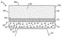
- FIG. 2illustrates an example composite article used in the gas turbine engine.
- FIG. 3illustrates an example method for forming a layer of the composite article.
- FIG. 4illustrates an example of montmorillonite wetting the surfaces of boron nitride.
- FIG. 1illustrates selected portions of an example gas turbine engine 10 , such as a gas turbine engine 10 used for propulsion.
- the gas turbine engine 10is circumferentially disposed about an engine centerline 12 .
- the engine 10includes a fan 14 , a compressor section 16 , a combustion section 18 and a turbine section 20 .
- Each of the compressor section 16 and the turbine section 20include blades 22 that are rotatable about the centerline 12 and non-rotatable vanes 24 .
- air compressed in the compressor section 16is mixed with fuel and burned in the combustion section 18 to produce hot gases that are expanded in the turbine section 20 .
- FIG. 1is a somewhat schematic presentation for illustrative purposes only and is not a limitation on the disclosed examples. Additionally, there are various types of gas turbine engines, many of which could benefit from the examples disclosed herein, which are not limited to the design shown.
- the gas turbine engine 10includes a plurality of articles 30 that are located radially outwards of corresponding blades 22 of the compressor section 16 and/or the turbine section 20 .
- the articles 30are outer air seals.
- the articles 30may be formed as portions of a case 32 that generally surrounds the compressor section 16 and/or the turbine section 20 .
- the articles 30may alternatively be mechanically attached to the case 32 in any suitable manner.
- a plurality of the articles 30may be mounted circumferentially about the compressor section 16 in a ring, for example.
- a plurality of the articles 30may also be used radially inwards of the vanes 24 of the compressor section 16 and/or the turbine section 20 .
- the articles 30may rotate with a shaft 31 of the engine 10 , or be located at the tips of the vanes 24 for sealing contact with a corresponding seal that rotates with the shaft 31 .
- the illustrated examplerefers to the articles 30 being located in the compressor section 16
- the articles 30are not limited to use in the compressor section 16 and may be used in the turbine section 20 or in non-aerospace applications.
- FIG. 2illustrates an example article 30 that includes a substrate 46 having an abradable coating system 48 disposed thereon.
- the article 30is a seal member that extends between a leading end 49 a and a trailing end 49 b , circumferential sides 49 c (one shown), and a first side 49 d and a second side 49 e .
- the abradable coating system 48is disposed on the second side 49 e , which may be a radially inner or outer side, depending on the location relative to the engine centerline A, blades 22 , and vanes 24 .
- the abradable coating system 48also includes a layer 50 and, optionally, a bond layer 52 between the layer 50 and the substrate 46 .
- the bond layer 52facilitates bonding between the layer 50 and the substrate 46 , but may not be needed if the protective properties of the bond layer 52 are not desired and/or if the layer 50 bonds to the substrate 46 with a desired amount of strength.
- the bond layer 52may be any suitable material for bonding.
- the bond layer 52may include a nickel alloy, platinum, gold, silver, or MCrAlY, where the M includes at least one of nickel, cobalt, iron, or a combination thereof, Cr is chromium, Al is aluminum and Y is yttrium.
- the layer 50functions as an abrasion layer with regard to the rotating blades 22 or stationary vanes 24 of the compressor section 16 , for example. That is, the layer 50 is abradable and may be worn away through contact with the tips of the blades 22 , tips of the vanes 24 , or a platform section of the vanes 24 to thereby facilitate efficient interaction between gas flow through the compressor section 16 and the blades 22 and vanes 24 . In this regard, the layer 50 wears away smoothly to facilitate maintaining an aerodynamic surface. For example, a worn away surface of the layer 50 may include a surface roughness of about 1-600 microinches (0.0254-15.25 micrometers). The layer 50 also provides strong bonding during deposition of the layer 50 , which facilitates economic manufacturing. The term “about” as used in this description relative to a given value refers to possible variation in the value, such as normally accepted variations or tolerances in the art.
- the layer 50is a composite of a metal phase 60 , a first ceramic phase 62 , and a second ceramic phase 64 .
- the materials of the metal phase 60 , the first ceramic phase 62 , and the second ceramic phase 64may be selected to provide desirable characteristics of the layer 50 , such as a desired density, porosity, abradability, and the like.
- the first ceramic phase 62 and the second ceramic phase 64may be selected from any of various types of ceramic materials.
- the first ceramic phase 62includes at least one of boron nitride or graphite
- the second ceramic phase 64includes at least one of a clay material or a metal oxide.
- the clay material or the metal oxide of the second ceramic phase 64agglomerates (e.g., clusters together) with the first ceramic phase 62 to facilitate adherence of the first ceramic phase 62 to the second ceramic phase 64 .
- the material selected for the second ceramic phase 64may exhibit hydrogen bonding or other polar interactions that facilitate agglomeration to thereby physically bind particles of the first ceramic phase 62 .
- agglomerationfacilitates adhering the first ceramic phase 62 to the second ceramic phase 64 and substrate 46 (or bond layer 52 , if used).
- a clayis a naturally occurring mineral, such as a phyllosilicate.
- the claymay be a hydrous aluminum phyllosilicate.
- the hydrous aluminum phyllosilicateincludes at least one of kaolinite, smectite, or chlorite. Any of the various types of kaolinite may be used, such as dicktite, halloysite, serpentine kaolinite, or nacrite.
- any of the various types of smectitemay be used, such as pyrophyllite, talc, vermiculite, sauconite, saponite, nontronite, or montmorillonite (e.g., bentonite).
- the claymay include any desired average particle size for achieving a desired degree of agglomeration. That is, relatively larger particles may have lower specific surface areas that do not facilitate agglomeration as well as smaller particles having higher specific surface areas.
- the claymay include an average particle size that is less than or equal to about 5 micrometers (196.9 microinches). In a further example, the clay includes an average particle size that is less than or equal to about 2 micrometers (78.7 microinches).
- a desired degree of agglomerationmay be achieved through the selection of clay and particle size according to the given examples.
- the metal oxidemay include at least one oxide of silicon, aluminum, titanium, zirconium, yttrium, chromium, molybdenum, iron, or copper. Given this description, one of ordinary skill in the art will be able to select other types of metal oxides to meet their particular needs.
- a combination of metal oxidesmay also be used.
- the combinationmay include any two or more of the given example oxides.
- the combinationincludes about 87 wt % of aluminum oxide and about 13 wt % of titanium dioxide.
- the combinationincludes about 93 wt % of zirconium oxide and about 7 wt % of yttrium oxide.
- the combinationincludes about 80 wt % of zirconium oxide and about 20 wt % of yttrium oxide.
- the combinationincludes about 60 wt % of zirconium oxide and about 40 wt % of aluminum oxide.
- the metal oxidemay be used with any desired particle size for achieving a desired degree of agglomeration with the first ceramic phase 62 .
- the metal oxide or combination of metal oxidesincludes an average particle size that is less than or equal to about 2 micrometers (78.7 microinches). In a further example, the metal oxide or combination of metal oxides includes an average particle size of less than or equal to about 1 micrometer (39.4 microinches). In yet a further example, the metal oxide or combination of metal oxides includes an average particle size that is less than or equal to about 200 nanometers (7.9 microinches).
- the metal oxidemay also be a silica-based glass.
- the silica-based glassmay also include an additive, such as sodium carbonate, calcium oxide, magnesium oxide, aluminum oxide, boron, lanthanum, lithium, barium, iron, or cerium oxide.
- the additivesmay be used to adjust the properties of the silica based glass, such as the melting point or physical properties.
- the additivesmay also vary the wetting properties of the silica-based glass. For example, boron in the silica-based glass may facilitate wetting between the silica-based glass and boron nitride as the first ceramic phase 62 .
- the second ceramic phase 64functions as a bonding agent between the first ceramic phase 62 and the metal phase 60 . That is, the ceramic material selected for the first ceramic phase 62 may not bond with a desired degree of strength to the metal phase 60 .
- the second ceramic phase 64binds the first ceramic phase 62 and bonds with the metal phase 60 to facilitate stronger bonding of the first ceramic phase 62 to the metal phase 60 .
- the metal phase 60may be selected from any suitable type of metal for an intended application.
- the metal phase 60may include nickel, copper, molybdenum, aluminum, or other metal phase.
- the metal phase 60may also be an alloy, such as a nickel alloy.
- nickel alloysare disclosed in co-owned U.S. Pat. Nos. 5,536,022 and 5,780,116, but the nickel alloys need not be limited to the alloys disclosed therein.
- the given example ceramic materials for the first ceramic phase 62 and the second ceramic phase 64may be utilized in the layer 50 in any desired combined amount for achieving desired characteristics of the layer 50 .
- the combined amountmay include about 1-33 wt % of the second ceramic phase 64 and a remainder being the first ceramic phase 62 .
- the combined amountincludes about 10-20 wt % of the second ceramic phase 64 and a remainder being the first ceramic phase 62 .
- the combined amountincludes about 10 wt % of the second ceramic phase 64 and a remainder being the first ceramic phase 62 .
- ceramic materials other than the given examplesmay be used in the above-disclosed amounts and therefore, the layer 50 need not be limited to the given compositions.
- the layer 50may include desired amounts of the metal phase 60 , the first ceramic phase 62 , and the second ceramic phase 64 for achieving desired characteristics of the layer 50 .
- the layer 50may include about 5-15 vol % porosity, about 20-66 vol % of the combined volume of the first ceramic phase 62 and the second ceramic phase 64 , and a remainder volume of the metal phase 60 .
- the porosity of the layer 50may be in the range of 5-15 vol %, but is not limited to the example porosity range.
- the layer 50has an architecture comprising the metal phase 60 as a matrix relative to the first ceramic phase 62 and the second ceramic phase 64 .
- the metal phase 60may still be interconnected as a matrix if the metal phase 60 is below 50 vol %.
- the first ceramic phase 62 and the second ceramic phase 64are agglomerated such that the second ceramic phase 64 at least partially surrounds the first ceramic phase 62 .
- the second ceramic phase 64may be a matrix relative to the first ceramic phase 62 .
- the layer 50may be formed using any of various types of techniques.
- FIG. 3illustrates one example method 80 for forming the layer 50 ; however, other types of methods may be used.
- the method 80is a thermal spraying process that utilizes a first powder 82 of the metal phase 60 and a second powder 84 that is a composite of the first ceramic phase 62 and the second ceramic phase 64 .
- the powders 82 and 84are fed into a thermal spray device 86 , which heats the powders 82 and 84 to a desired temperature and sprays the powders 82 and 84 onto the substrate 46 to thereby form the layer 50 .
- the powder 84comprises composite particles of the first ceramic phase 62 and second ceramic phase 64 .
- the particlesmay be formed using any desired particle forming technique such as, but not limited to, radio frequency plasma formation, spray drying, tumbling, caking, sintering, crushing, melt slurry formation, atomizing, and combinations thereof.
- the powder 84also includes a polymer, to bind the first ceramic phase 62 and the second ceramic phase 64 together.
- the polymermay be used when relatively large particle sizes of the second ceramic phase 64 are used, such as particles larger than about 2 micrometers (78.7 microinches). The larger particles may have lower specific surface areas that do not agglomerate as well as smaller particles having higher specific surface areas. Additionally, if the material selected for the second ceramic phase 64 does not agglomerate to a desired degree, the polymer may be used to facilitate binding the first ceramic phase 62 in the powder 84 .
- the polymermay be polyvinylalcohol. Given this description, one of ordinary skill in the art will recognize other types of polymers to suit their particular needs.
- the thermal spray device 86heats and melts at least a portion of the powder 82 and a portion of the powder 84 . That is, the metal phase 60 of the powder 82 melts and the second ceramic phase 64 of the powder 84 melts.
- the first ceramic phase 62does not melt in the process and remains solid.
- the selected temperature used in the thermal spray processmay not exceed the melting temperature of the first ceramic phases 62 .
- the unmelted first ceramic phase 62would normally be prone to deflecting off of the substrate 46 (or bond layer 52 , if used) upon impact during the spraying process.
- the melted second ceramic phase 64facilitates adhering the unmelted first ceramic phase 62 to the substrate 46 by wetting the surfaces of the unmelted first ceramic phase 62 .
- the melted second ceramic phase 64thereby functions as a bonding agent to facilitate “sticking” the unmelted first ceramic phase 62 to the substrate 46 (or bond layer 52 , if used) and metal phase 60 .
- the metal phase 60may not significantly wet the unmelted first ceramic phase 62 .
- the metal phase 60may not be chemically compatible with wetting the surfaces of the unmelted phase.
- the phases 62 and 64are agglomerated in the powder 84 such that the phases 62 and 64 are already in fused contact when fed into the device 86 , which facilitates a contact between the phases 62 and 64 during spraying to promote wetting.
- the ceramic materials used for the phases 62 and 64are chemically compatible such that the melted second ceramic phase 64 wets the unmelted first ceramic phase 62 . The degree of compatibility may vary, depending on the type of ceramic material selected.
- first ceramic phase 62is boron nitride and the second ceramic phase 64 is montmorillonite
- boron nitridesublimes around 5200° F. (about 2871° C.) but does not melt under the lower temperatures that are used to melt the montmorillonite and metal phase 60 for the thermal spray process.
- the montmorillonitewets the surfaces of the boron nitride, as shown schematically in FIG. 4 , for example. Hydrogen bonding interactions or other polar interactions between the melted montmorillonite and the unmelted boron nitride facilitate relatively low angle wetting.
- the melted montmorillonitethereby functions as a binding agent to facilitate adhering the boron nitride to the metal phase 60 and substrate 46 (or bond layer 52 , if used).
- the types of materials selected for the first ceramic phase 62 and the second ceramic phase 64may determine the degree of wetting that occurs between the melted and unmelted phases, and thus also determine the degree to which the melted phase facilitates adherence.
- the binding provided by the second ceramic phase 64 during the spraying processfacilitates economic manufacturing of the layer 50 and a desirable degree of abradability. For example, the binding facilitates consuming less of the first ceramic phase 62 than would otherwise be consumed without using the second ceramic phase 64 because deflection off of the substrate 46 may be reduced. Also, the spraying process may be conducted at higher speeds because of the reduced deflection. Additionally, the second ceramic phase 64 reduces an amount of the first ceramic phase 62 and metal phase 60 that are used. Thus, if expensive materials are used for the first ceramic phase 62 and the metal phase 60 , the expense associated with using these materials for the layer 50 is reduced.
- the bonding characteristics of the second ceramic phase 64increases the strength and resistance to erosion of the abradable layer 50 , allowing the amount of first ceramic phase 62 and second ceramic phase 64 that is used in the layer 50 to be increased thereby reducing the overall density of the layer 50 , which in turn results in the gas turbine engine 10 being lighter. Better bonding equates to improved erosion resistance for a given density abradable, thereby allowing more low density ceramic phase to be used and reducing the density of the composite.
Landscapes
- Chemical & Material Sciences (AREA)
- Engineering & Computer Science (AREA)
- Chemical Kinetics & Catalysis (AREA)
- Materials Engineering (AREA)
- Mechanical Engineering (AREA)
- Metallurgy (AREA)
- Organic Chemistry (AREA)
- Physics & Mathematics (AREA)
- Plasma & Fusion (AREA)
- Laminated Bodies (AREA)
- Structures Of Non-Positive Displacement Pumps (AREA)
Abstract
Description
Claims (28)
Priority Applications (3)
| Application Number | Priority Date | Filing Date | Title |
|---|---|---|---|
| US11/946,100US7998604B2 (en) | 2007-11-28 | 2007-11-28 | Article having composite layer |
| EP08253834.9AEP2067872B1 (en) | 2007-11-28 | 2008-11-28 | Article having composite layer |
| US13/171,732US20110256321A1 (en) | 2007-11-28 | 2011-06-29 | Article having composite layer |
Applications Claiming Priority (1)
| Application Number | Priority Date | Filing Date | Title |
|---|---|---|---|
| US11/946,100US7998604B2 (en) | 2007-11-28 | 2007-11-28 | Article having composite layer |
Related Child Applications (1)
| Application Number | Title | Priority Date | Filing Date |
|---|---|---|---|
| US13/171,732DivisionUS20110256321A1 (en) | 2007-11-28 | 2011-06-29 | Article having composite layer |
Publications (2)
| Publication Number | Publication Date |
|---|---|
| US20090136740A1 US20090136740A1 (en) | 2009-05-28 |
| US7998604B2true US7998604B2 (en) | 2011-08-16 |
Family
ID=40326498
Family Applications (2)
| Application Number | Title | Priority Date | Filing Date |
|---|---|---|---|
| US11/946,100Active2030-01-20US7998604B2 (en) | 2007-11-28 | 2007-11-28 | Article having composite layer |
| US13/171,732AbandonedUS20110256321A1 (en) | 2007-11-28 | 2011-06-29 | Article having composite layer |
Family Applications After (1)
| Application Number | Title | Priority Date | Filing Date |
|---|---|---|---|
| US13/171,732AbandonedUS20110256321A1 (en) | 2007-11-28 | 2011-06-29 | Article having composite layer |
Country Status (2)
| Country | Link |
|---|---|
| US (2) | US7998604B2 (en) |
| EP (1) | EP2067872B1 (en) |
Cited By (14)
| Publication number | Priority date | Publication date | Assignee | Title |
|---|---|---|---|---|
| US20120099973A1 (en)* | 2010-10-25 | 2012-04-26 | United Technologies Corporation | Low density abradable coating with fine porosity |
| US20160305257A1 (en)* | 2015-04-15 | 2016-10-20 | United Technologies Corporation | Abrasive Tip Blade Manufacture Methods |
| US9550230B2 (en) | 2011-09-16 | 2017-01-24 | United Technologies Corporation | Mold for casting a workpiece that includes one or more casting pins |
| US20170314566A1 (en)* | 2016-04-29 | 2017-11-02 | United Technologies Corporation | Organic Matrix Abradable Coating Resistant to Clogging of Abrasive Blade Tips |
| US20170314570A1 (en)* | 2016-04-29 | 2017-11-02 | United Technologies Corporation | Abrasive Blade Tips With Additive Layer Resistant to Clogging |
| US9856163B2 (en) | 2015-04-15 | 2018-01-02 | Owens-Brockway Glass Container Inc. | Nanocomposite material |
| US20180230842A1 (en)* | 2016-03-23 | 2018-08-16 | United Technologies Corporation | Outer Airseal Abradable Rub Strip |
| US10065243B2 (en) | 2012-10-01 | 2018-09-04 | United Technologies Corporation | Aluminum based abradable material with reduced metal transfer to blades |
| US10422242B2 (en) | 2016-04-29 | 2019-09-24 | United Technologies Corporation | Abrasive blade tips with additive resistant to clogging by organic matrix abradable |
| US10655492B2 (en) | 2016-04-29 | 2020-05-19 | United Technologies Corporation | Abrasive blade tips with additive resistant to clogging by organic matrix abradable |
| US20220018291A1 (en)* | 2020-07-16 | 2022-01-20 | Raytheon Technologies Corporation | Gas turbine engine including seal assembly with abradable coating including magnetic particles |
| US20220018290A1 (en)* | 2020-07-16 | 2022-01-20 | Raytheon Technologies Corporation | Gas turbine engine including seal assembly with abradable coating and cutter |
| US20220018289A1 (en)* | 2020-07-16 | 2022-01-20 | Raytheon Technologies Corporation | Gas turbine engine including seal assembly with abradable coating including magnetic particles embedded in polymer |
| US12158210B2 (en) | 2020-02-27 | 2024-12-03 | Rtx Corporation | Self-lubricating, wear resistant piston seal |
Families Citing this family (21)
| Publication number | Priority date | Publication date | Assignee | Title |
|---|---|---|---|---|
| US20110027573A1 (en)* | 2009-08-03 | 2011-02-03 | United Technologies Corporation | Lubricated Abradable Coating |
| US8562290B2 (en) | 2010-04-01 | 2013-10-22 | United Technologies Corporation | Blade outer air seal with improved efficiency |
| US20120196139A1 (en)* | 2010-07-14 | 2012-08-02 | Christopher Petorak | Thermal spray composite coatings for semiconductor applications |
| US8727712B2 (en)* | 2010-09-14 | 2014-05-20 | United Technologies Corporation | Abradable coating with safety fuse |
| US8770927B2 (en)* | 2010-10-25 | 2014-07-08 | United Technologies Corporation | Abrasive cutter formed by thermal spray and post treatment |
| US8770926B2 (en)* | 2010-10-25 | 2014-07-08 | United Technologies Corporation | Rough dense ceramic sealing surface in turbomachines |
| US8790078B2 (en) | 2010-10-25 | 2014-07-29 | United Technologies Corporation | Abrasive rotor shaft ceramic coating |
| US9169740B2 (en) | 2010-10-25 | 2015-10-27 | United Technologies Corporation | Friable ceramic rotor shaft abrasive coating |
| US20120189434A1 (en)* | 2011-01-26 | 2012-07-26 | United Technologies Corporation | Coating with abradability proportional to interaction rate |
| US8876470B2 (en) | 2011-06-29 | 2014-11-04 | United Technologies Corporation | Spall resistant abradable turbine air seal |
| US9145787B2 (en)* | 2011-08-17 | 2015-09-29 | General Electric Company | Rotatable component, coating and method of coating the rotatable component of an engine |
| US9341066B2 (en)* | 2012-06-18 | 2016-05-17 | United Technologies Corporation | Turbine compressor blade tip resistant to metal transfer |
| FR2994397B1 (en) | 2012-08-07 | 2014-08-01 | Snecma | COATING IN ABRADABLE MATERIAL WITH LOW SURFACE ROUGHNESS |
| FR2999457B1 (en)* | 2012-12-18 | 2015-01-16 | Commissariat Energie Atomique | METHOD FOR COATING A SUBSTRATE WITH A CERAMIC ABRADABLE MATERIAL, AND COATING THUS OBTAINED |
| DE102013218687A1 (en)* | 2013-09-18 | 2015-04-02 | MTU Aero Engines AG | Galvanized wear protection coating and method therefor |
| US10513942B2 (en) | 2013-12-10 | 2019-12-24 | United Technologies Corporation | Fusible bond for gas turbine engine coating system |
| CN104404434B (en)* | 2014-11-05 | 2016-09-21 | 昆明理工大学 | A kind of ceramic coating of metal material surface and preparation method thereof |
| US9896756B2 (en)* | 2015-06-02 | 2018-02-20 | United Technologies Corporation | Abradable seal and method of producing a seal |
| US10125274B2 (en)* | 2016-05-03 | 2018-11-13 | Baker Hughes, A Ge Company, Llc | Coatings containing carbon composite fillers and methods of manufacture |
| US10697464B2 (en)* | 2016-07-29 | 2020-06-30 | Raytheon Technologies Corporation | Abradable material |
| CN111763902B (en)* | 2020-07-13 | 2021-03-16 | 中国人民解放军陆军装甲兵学院 | Powder core wire and preparation method thereof, and anti-corrosion wear-resistant composite coating and preparation method thereof |
Citations (22)
| Publication number | Priority date | Publication date | Assignee | Title |
|---|---|---|---|---|
| US3084064A (en) | 1959-08-06 | 1963-04-02 | Union Carbide Corp | Abradable metal coatings and process therefor |
| US3342626A (en) | 1963-10-02 | 1967-09-19 | Avco Corp | Flame spray metallizing |
| US3879831A (en) | 1971-11-15 | 1975-04-29 | United Aircraft Corp | Nickle base high temperature abradable material |
| US4664973A (en) | 1983-12-27 | 1987-05-12 | United Technologies Corporation | Porous metal abradable seal material |
| US4783341A (en) | 1987-05-04 | 1988-11-08 | United Technologies Corporation | Method and apparatus for measuring the density and hardness of porous plasma sprayed coatings |
| EP0426485A2 (en) | 1989-11-03 | 1991-05-08 | Advanced Ceramics Corporation | Powder coating compositions |
| GB2273109A (en) | 1992-12-07 | 1994-06-08 | Ford Motor Co | Composite metalising wire containing lubricant and/or wear resistant particle method for producing said wire |
| US5536022A (en) | 1990-08-24 | 1996-07-16 | United Technologies Corporation | Plasma sprayed abradable seals for gas turbine engines |
| GB2317899A (en) | 1996-10-02 | 1998-04-08 | Westaim Technologies Inc | Abradable seal assembly |
| US5780171A (en)* | 1995-09-26 | 1998-07-14 | United Technologies Corporation | Gas turbine engine component |
| WO1999036590A1 (en) | 1998-01-16 | 1999-07-22 | Dresser Industries, Inc. | Hardfacing having coated ceramic particles or coated particles of other hard materials |
| US5966585A (en) | 1984-09-18 | 1999-10-12 | Union Carbide Coatings Service Corporation | Titanium carbide/tungsten boride coatings |
| EP1077272A1 (en) | 1999-08-16 | 2001-02-21 | Praxair Technology, Inc. | Titanium carbide/tungsten boride coatings |
| US20020064667A1 (en) | 1998-02-27 | 2002-05-30 | Scheckenbach Dl. Helmut | Thermal spray powder incorporating a particular high temperature polymer |
| US6537021B2 (en) | 2001-06-06 | 2003-03-25 | Chromalloy Gas Turbine Corporation | Abradeable seal system |
| US20030180565A1 (en)* | 2000-09-21 | 2003-09-25 | Christian Herbst-Dederichs | Thermally applied coating for piston rings, consisting of mechanically alloyed powders |
| WO2003104511A2 (en) | 2002-06-07 | 2003-12-18 | The Westaim Corporation | Thermal spray compositions for abradable seals |
| US6730413B2 (en) | 2001-07-31 | 2004-05-04 | General Electric Company | Thermal barrier coating |
| EP1428600A1 (en) | 2002-12-13 | 2004-06-16 | Snecma Moteurs | Pulverulent material for abradable seal |
| WO2005002742A1 (en) | 2003-02-07 | 2005-01-13 | Diamond Innovations, Inc. | Process equipment wear surfaces of extended resistance and methods for their manufacture |
| US20050124505A1 (en)* | 2003-12-05 | 2005-06-09 | Karel Hajmrle | Method for producing composite material for coating applications |
| US20050287348A1 (en)* | 2004-06-24 | 2005-12-29 | Faler Dennis L | Nanoparticle coatings for flexible and/or drawable substrates |
Family Cites Families (6)
| Publication number | Priority date | Publication date | Assignee | Title |
|---|---|---|---|---|
| US2984555A (en)* | 1958-04-09 | 1961-05-16 | Norton Co | Mounted points |
| US3490930A (en)* | 1967-08-07 | 1970-01-20 | Kaiser Aluminium Chem Corp | Refractory composition |
| US4566700A (en)* | 1982-08-09 | 1986-01-28 | United Technologies Corporation | Abrasive/abradable gas path seal system |
| EP1593445B1 (en)* | 2004-05-03 | 2007-07-18 | Siemens Aktiengesellschaft | Process of making a hollow member having an internal coating |
| US7165946B2 (en)* | 2004-06-21 | 2007-01-23 | Solar Turbine Incorporated | Low-mid turbine temperature abradable coating |
| ITMI20072292A1 (en)* | 2007-12-06 | 2009-06-07 | Itea Spa | COMBUSTION PROCESS |
- 2007
- 2007-11-28USUS11/946,100patent/US7998604B2/enactiveActive
- 2008
- 2008-11-28EPEP08253834.9Apatent/EP2067872B1/enactiveActive
- 2011
- 2011-06-29USUS13/171,732patent/US20110256321A1/ennot_activeAbandoned
Patent Citations (25)
| Publication number | Priority date | Publication date | Assignee | Title |
|---|---|---|---|---|
| US3084064A (en) | 1959-08-06 | 1963-04-02 | Union Carbide Corp | Abradable metal coatings and process therefor |
| US3342626A (en) | 1963-10-02 | 1967-09-19 | Avco Corp | Flame spray metallizing |
| US3879831A (en) | 1971-11-15 | 1975-04-29 | United Aircraft Corp | Nickle base high temperature abradable material |
| US4664973A (en) | 1983-12-27 | 1987-05-12 | United Technologies Corporation | Porous metal abradable seal material |
| US5966585A (en) | 1984-09-18 | 1999-10-12 | Union Carbide Coatings Service Corporation | Titanium carbide/tungsten boride coatings |
| US4783341A (en) | 1987-05-04 | 1988-11-08 | United Technologies Corporation | Method and apparatus for measuring the density and hardness of porous plasma sprayed coatings |
| EP0426485A2 (en) | 1989-11-03 | 1991-05-08 | Advanced Ceramics Corporation | Powder coating compositions |
| US5780116A (en) | 1990-08-24 | 1998-07-14 | United Technologies Corporation | Method for producing an abradable seal |
| US5536022A (en) | 1990-08-24 | 1996-07-16 | United Technologies Corporation | Plasma sprayed abradable seals for gas turbine engines |
| GB2273109A (en) | 1992-12-07 | 1994-06-08 | Ford Motor Co | Composite metalising wire containing lubricant and/or wear resistant particle method for producing said wire |
| US5780171A (en)* | 1995-09-26 | 1998-07-14 | United Technologies Corporation | Gas turbine engine component |
| GB2317899A (en) | 1996-10-02 | 1998-04-08 | Westaim Technologies Inc | Abradable seal assembly |
| US5976695A (en) | 1996-10-02 | 1999-11-02 | Westaim Technologies, Inc. | Thermally sprayable powder materials having an alloyed metal phase and a solid lubricant ceramic phase and abradable seal assemblies manufactured therefrom |
| WO1999036590A1 (en) | 1998-01-16 | 1999-07-22 | Dresser Industries, Inc. | Hardfacing having coated ceramic particles or coated particles of other hard materials |
| US20020064667A1 (en) | 1998-02-27 | 2002-05-30 | Scheckenbach Dl. Helmut | Thermal spray powder incorporating a particular high temperature polymer |
| EP1077272A1 (en) | 1999-08-16 | 2001-02-21 | Praxair Technology, Inc. | Titanium carbide/tungsten boride coatings |
| US20030180565A1 (en)* | 2000-09-21 | 2003-09-25 | Christian Herbst-Dederichs | Thermally applied coating for piston rings, consisting of mechanically alloyed powders |
| US6537021B2 (en) | 2001-06-06 | 2003-03-25 | Chromalloy Gas Turbine Corporation | Abradeable seal system |
| US6730413B2 (en) | 2001-07-31 | 2004-05-04 | General Electric Company | Thermal barrier coating |
| WO2003104511A2 (en) | 2002-06-07 | 2003-12-18 | The Westaim Corporation | Thermal spray compositions for abradable seals |
| US6887530B2 (en)* | 2002-06-07 | 2005-05-03 | Sulzer Metco (Canada) Inc. | Thermal spray compositions for abradable seals |
| EP1428600A1 (en) | 2002-12-13 | 2004-06-16 | Snecma Moteurs | Pulverulent material for abradable seal |
| WO2005002742A1 (en) | 2003-02-07 | 2005-01-13 | Diamond Innovations, Inc. | Process equipment wear surfaces of extended resistance and methods for their manufacture |
| US20050124505A1 (en)* | 2003-12-05 | 2005-06-09 | Karel Hajmrle | Method for producing composite material for coating applications |
| US20050287348A1 (en)* | 2004-06-24 | 2005-12-29 | Faler Dennis L | Nanoparticle coatings for flexible and/or drawable substrates |
Non-Patent Citations (3)
| Title |
|---|
| Christie et al., Mineral Commodity Report 20-Clays, obtained Oct. 2010.* |
| Encyclopedia Britannica (www.britannica.com).* |
| EP Search Report dated May 6, 2011. |
Cited By (23)
| Publication number | Priority date | Publication date | Assignee | Title |
|---|---|---|---|---|
| US20120099973A1 (en)* | 2010-10-25 | 2012-04-26 | United Technologies Corporation | Low density abradable coating with fine porosity |
| US8936432B2 (en)* | 2010-10-25 | 2015-01-20 | United Technologies Corporation | Low density abradable coating with fine porosity |
| US9550230B2 (en) | 2011-09-16 | 2017-01-24 | United Technologies Corporation | Mold for casting a workpiece that includes one or more casting pins |
| US10065243B2 (en) | 2012-10-01 | 2018-09-04 | United Technologies Corporation | Aluminum based abradable material with reduced metal transfer to blades |
| US20160305257A1 (en)* | 2015-04-15 | 2016-10-20 | United Technologies Corporation | Abrasive Tip Blade Manufacture Methods |
| US11732595B2 (en) | 2015-04-15 | 2023-08-22 | Raytheon Technologies Corporation | Abrasive tip blade manufacture methods |
| US9856163B2 (en) | 2015-04-15 | 2018-01-02 | Owens-Brockway Glass Container Inc. | Nanocomposite material |
| US10450876B2 (en)* | 2015-04-15 | 2019-10-22 | United Technologies Corporation | Abrasive tip blade manufacture methods |
| US10669878B2 (en)* | 2016-03-23 | 2020-06-02 | Raytheon Technologies Corporation | Outer airseal abradable rub strip |
| US20180230842A1 (en)* | 2016-03-23 | 2018-08-16 | United Technologies Corporation | Outer Airseal Abradable Rub Strip |
| US10422242B2 (en) | 2016-04-29 | 2019-09-24 | United Technologies Corporation | Abrasive blade tips with additive resistant to clogging by organic matrix abradable |
| US10233938B2 (en)* | 2016-04-29 | 2019-03-19 | United Technologies Corporation | Organic matrix abradable coating resistant to clogging of abrasive blade tips |
| US10655492B2 (en) | 2016-04-29 | 2020-05-19 | United Technologies Corporation | Abrasive blade tips with additive resistant to clogging by organic matrix abradable |
| US10670045B2 (en)* | 2016-04-29 | 2020-06-02 | Raytheon Technologies Corporation | Abrasive blade tips with additive layer resistant to clogging |
| US20170314570A1 (en)* | 2016-04-29 | 2017-11-02 | United Technologies Corporation | Abrasive Blade Tips With Additive Layer Resistant to Clogging |
| US20170314566A1 (en)* | 2016-04-29 | 2017-11-02 | United Technologies Corporation | Organic Matrix Abradable Coating Resistant to Clogging of Abrasive Blade Tips |
| US12158210B2 (en) | 2020-02-27 | 2024-12-03 | Rtx Corporation | Self-lubricating, wear resistant piston seal |
| US20220018291A1 (en)* | 2020-07-16 | 2022-01-20 | Raytheon Technologies Corporation | Gas turbine engine including seal assembly with abradable coating including magnetic particles |
| US20220018290A1 (en)* | 2020-07-16 | 2022-01-20 | Raytheon Technologies Corporation | Gas turbine engine including seal assembly with abradable coating and cutter |
| US20220018289A1 (en)* | 2020-07-16 | 2022-01-20 | Raytheon Technologies Corporation | Gas turbine engine including seal assembly with abradable coating including magnetic particles embedded in polymer |
| US11293351B2 (en)* | 2020-07-16 | 2022-04-05 | Raytheon Technologies Corporation | Gas turbine engine including seal assembly with abradable coating including magnetic particles embedded in polymer |
| US11313280B2 (en)* | 2020-07-16 | 2022-04-26 | Raytheon Technologies Corporation | Gas turbine engine including seal assembly with abradable coating and cutter |
| US11313281B2 (en)* | 2020-07-16 | 2022-04-26 | Raytheon Technologies Corporation | Gas turbine engine including seal assembly with abradable coating including magnetic particles |
Also Published As
| Publication number | Publication date |
|---|---|
| EP2067872A3 (en) | 2011-06-08 |
| EP2067872B1 (en) | 2017-07-26 |
| US20090136740A1 (en) | 2009-05-28 |
| EP2067872A2 (en) | 2009-06-10 |
| US20110256321A1 (en) | 2011-10-20 |
Similar Documents
| Publication | Publication Date | Title |
|---|---|---|
| US7998604B2 (en) | Article having composite layer | |
| US8777562B2 (en) | Blade air seal with integral barrier | |
| US9926794B2 (en) | Turbine blade tip treatment for industrial gas turbines | |
| US5059095A (en) | Turbine rotor blade tip coated with alumina-zirconia ceramic | |
| RU2451043C2 (en) | Strontium and titanium oxides and abrasive coatings obtained on their basis | |
| JP5788906B2 (en) | Abrasive composition and method for producing the same | |
| EP1583850B1 (en) | Thermal spray composition and method of deposition for abradable seals | |
| EP2372104B1 (en) | Blade outer air seal with improved efficiency | |
| EP3276038B1 (en) | Abradable material | |
| EP2578804B1 (en) | Method of manufacturing an abradable air seal | |
| JP2008082331A (en) | Abradable seal | |
| US20080113105A1 (en) | Coating Formed By Thermal Spraying And Methods For The Formation Thereof | |
| CN103060799A (en) | Material for improving self-lubricating and wear-resisting performances of titanium alloy surface and application for same | |
| CA3080622A1 (en) | Mechanically alloyed metallic thermal spray coating material and thermal spray coating method utilizing the same | |
| JP7590967B2 (en) | Mechanically alloyed metal spray coating material and spray coating method using the same | |
| JP6457420B2 (en) | Powder for thermal spraying and film forming method of abradable thermal spray coating using the same | |
| US12037910B2 (en) | Fusible bond for gas turbine engine coating system | |
| US20100068405A1 (en) | Method of forming metallic carbide based wear resistant coating on a combustion turbine component | |
| US20250050411A1 (en) | Porous agglomerates and encapsulated agglomerates for abradable sealant materials and methods of manufacturing the same |
Legal Events
| Date | Code | Title | Description |
|---|---|---|---|
| AS | Assignment | Owner name:UNITED TECHNOLOGIES CORPORATION, CONNECTICUT Free format text:ASSIGNMENT OF ASSIGNORS INTEREST;ASSIGNORS:REYNOLDS, GEORGE H.;STROCK, CHRISTOPHER W.;REEL/FRAME:020168/0541 Effective date:20071127 | |
| STCF | Information on status: patent grant | Free format text:PATENTED CASE | |
| FPAY | Fee payment | Year of fee payment:4 | |
| MAFP | Maintenance fee payment | Free format text:PAYMENT OF MAINTENANCE FEE, 8TH YEAR, LARGE ENTITY (ORIGINAL EVENT CODE: M1552); ENTITY STATUS OF PATENT OWNER: LARGE ENTITY Year of fee payment:8 | |
| AS | Assignment | Owner name:RAYTHEON TECHNOLOGIES CORPORATION, MASSACHUSETTS Free format text:CHANGE OF NAME;ASSIGNOR:UNITED TECHNOLOGIES CORPORATION;REEL/FRAME:054062/0001 Effective date:20200403 | |
| AS | Assignment | Owner name:RAYTHEON TECHNOLOGIES CORPORATION, CONNECTICUT Free format text:CORRECTIVE ASSIGNMENT TO CORRECT THE AND REMOVE PATENT APPLICATION NUMBER 11886281 AND ADD PATENT APPLICATION NUMBER 14846874. TO CORRECT THE RECEIVING PARTY ADDRESS PREVIOUSLY RECORDED AT REEL: 054062 FRAME: 0001. ASSIGNOR(S) HEREBY CONFIRMS THE CHANGE OF ADDRESS;ASSIGNOR:UNITED TECHNOLOGIES CORPORATION;REEL/FRAME:055659/0001 Effective date:20200403 | |
| MAFP | Maintenance fee payment | Free format text:PAYMENT OF MAINTENANCE FEE, 12TH YEAR, LARGE ENTITY (ORIGINAL EVENT CODE: M1553); ENTITY STATUS OF PATENT OWNER: LARGE ENTITY Year of fee payment:12 | |
| AS | Assignment | Owner name:RTX CORPORATION, CONNECTICUT Free format text:CHANGE OF NAME;ASSIGNOR:RAYTHEON TECHNOLOGIES CORPORATION;REEL/FRAME:064714/0001 Effective date:20230714 |