US7998178B2 - Linked bilateral spinal facet implants and methods of use - Google Patents
Linked bilateral spinal facet implants and methods of useDownload PDFInfo
- Publication number
- US7998178B2 US7998178B2US12/240,281US24028108AUS7998178B2US 7998178 B2US7998178 B2US 7998178B2US 24028108 AUS24028108 AUS 24028108AUS 7998178 B2US7998178 B2US 7998178B2
- Authority
- US
- United States
- Prior art keywords
- vertebra
- inferior
- facet
- prosthesis
- superior
- Prior art date
- Legal status (The legal status is an assumption and is not a legal conclusion. Google has not performed a legal analysis and makes no representation as to the accuracy of the status listed.)
- Expired - Lifetime, expires
Links
Images


Classifications
- A—HUMAN NECESSITIES
- A61—MEDICAL OR VETERINARY SCIENCE; HYGIENE
- A61F—FILTERS IMPLANTABLE INTO BLOOD VESSELS; PROSTHESES; DEVICES PROVIDING PATENCY TO, OR PREVENTING COLLAPSING OF, TUBULAR STRUCTURES OF THE BODY, e.g. STENTS; ORTHOPAEDIC, NURSING OR CONTRACEPTIVE DEVICES; FOMENTATION; TREATMENT OR PROTECTION OF EYES OR EARS; BANDAGES, DRESSINGS OR ABSORBENT PADS; FIRST-AID KITS
- A61F2/00—Filters implantable into blood vessels; Prostheses, i.e. artificial substitutes or replacements for parts of the body; Appliances for connecting them with the body; Devices providing patency to, or preventing collapsing of, tubular structures of the body, e.g. stents
- A61F2/02—Prostheses implantable into the body
- A61F2/30—Joints
- A61F2/44—Joints for the spine, e.g. vertebrae, spinal discs
- A61F2/4405—Joints for the spine, e.g. vertebrae, spinal discs for apophyseal or facet joints, i.e. between adjacent spinous or transverse processes
- A—HUMAN NECESSITIES
- A61—MEDICAL OR VETERINARY SCIENCE; HYGIENE
- A61B—DIAGNOSIS; SURGERY; IDENTIFICATION
- A61B17/00—Surgical instruments, devices or methods
- A61B17/56—Surgical instruments or methods for treatment of bones or joints; Devices specially adapted therefor
- A61B17/58—Surgical instruments or methods for treatment of bones or joints; Devices specially adapted therefor for osteosynthesis, e.g. bone plates, screws or setting implements
- A61B17/68—Internal fixation devices, including fasteners and spinal fixators, even if a part thereof projects from the skin
- A61B17/70—Spinal positioners or stabilisers, e.g. stabilisers comprising fluid filler in an implant
- A61B17/7062—Devices acting on, attached to, or simulating the effect of, vertebral processes, vertebral facets or ribs ; Tools for such devices
- A61B17/7064—Devices acting on, attached to, or simulating the effect of, vertebral facets; Tools therefor
- A—HUMAN NECESSITIES
- A61—MEDICAL OR VETERINARY SCIENCE; HYGIENE
- A61B—DIAGNOSIS; SURGERY; IDENTIFICATION
- A61B17/00—Surgical instruments, devices or methods
- A61B17/56—Surgical instruments or methods for treatment of bones or joints; Devices specially adapted therefor
- A61B17/58—Surgical instruments or methods for treatment of bones or joints; Devices specially adapted therefor for osteosynthesis, e.g. bone plates, screws or setting implements
- A61B17/68—Internal fixation devices, including fasteners and spinal fixators, even if a part thereof projects from the skin
- A61B17/70—Spinal positioners or stabilisers, e.g. stabilisers comprising fluid filler in an implant
- A61B17/7062—Devices acting on, attached to, or simulating the effect of, vertebral processes, vertebral facets or ribs ; Tools for such devices
- A61B17/7067—Devices bearing against one or more spinous processes and also attached to another part of the spine; Tools therefor
- A—HUMAN NECESSITIES
- A61—MEDICAL OR VETERINARY SCIENCE; HYGIENE
- A61B—DIAGNOSIS; SURGERY; IDENTIFICATION
- A61B17/00—Surgical instruments, devices or methods
- A61B17/56—Surgical instruments or methods for treatment of bones or joints; Devices specially adapted therefor
- A61B17/58—Surgical instruments or methods for treatment of bones or joints; Devices specially adapted therefor for osteosynthesis, e.g. bone plates, screws or setting implements
- A61B17/68—Internal fixation devices, including fasteners and spinal fixators, even if a part thereof projects from the skin
- A61B17/84—Fasteners therefor or fasteners being internal fixation devices
- A61B17/86—Pins or screws or threaded wires; nuts therefor
- A61B17/8625—Shanks, i.e. parts contacting bone tissue
- A—HUMAN NECESSITIES
- A61—MEDICAL OR VETERINARY SCIENCE; HYGIENE
- A61F—FILTERS IMPLANTABLE INTO BLOOD VESSELS; PROSTHESES; DEVICES PROVIDING PATENCY TO, OR PREVENTING COLLAPSING OF, TUBULAR STRUCTURES OF THE BODY, e.g. STENTS; ORTHOPAEDIC, NURSING OR CONTRACEPTIVE DEVICES; FOMENTATION; TREATMENT OR PROTECTION OF EYES OR EARS; BANDAGES, DRESSINGS OR ABSORBENT PADS; FIRST-AID KITS
- A61F2/00—Filters implantable into blood vessels; Prostheses, i.e. artificial substitutes or replacements for parts of the body; Appliances for connecting them with the body; Devices providing patency to, or preventing collapsing of, tubular structures of the body, e.g. stents
- A61F2/02—Prostheses implantable into the body
- A61F2/30—Joints
- A61F2/30767—Special external or bone-contacting surface, e.g. coating for improving bone ingrowth
- A61F2/30771—Special external or bone-contacting surface, e.g. coating for improving bone ingrowth applied in original prostheses, e.g. holes or grooves
- A—HUMAN NECESSITIES
- A61—MEDICAL OR VETERINARY SCIENCE; HYGIENE
- A61F—FILTERS IMPLANTABLE INTO BLOOD VESSELS; PROSTHESES; DEVICES PROVIDING PATENCY TO, OR PREVENTING COLLAPSING OF, TUBULAR STRUCTURES OF THE BODY, e.g. STENTS; ORTHOPAEDIC, NURSING OR CONTRACEPTIVE DEVICES; FOMENTATION; TREATMENT OR PROTECTION OF EYES OR EARS; BANDAGES, DRESSINGS OR ABSORBENT PADS; FIRST-AID KITS
- A61F2/00—Filters implantable into blood vessels; Prostheses, i.e. artificial substitutes or replacements for parts of the body; Appliances for connecting them with the body; Devices providing patency to, or preventing collapsing of, tubular structures of the body, e.g. stents
- A61F2/02—Prostheses implantable into the body
- A61F2/30—Joints
- A61F2/46—Special tools for implanting artificial joints
- A61F2/4603—Special tools for implanting artificial joints for insertion or extraction of endoprosthetic joints or of accessories thereof
- A61F2/4611—Special tools for implanting artificial joints for insertion or extraction of endoprosthetic joints or of accessories thereof of spinal prostheses
- A—HUMAN NECESSITIES
- A61—MEDICAL OR VETERINARY SCIENCE; HYGIENE
- A61B—DIAGNOSIS; SURGERY; IDENTIFICATION
- A61B17/00—Surgical instruments, devices or methods
- A61B17/56—Surgical instruments or methods for treatment of bones or joints; Devices specially adapted therefor
- A61B17/58—Surgical instruments or methods for treatment of bones or joints; Devices specially adapted therefor for osteosynthesis, e.g. bone plates, screws or setting implements
- A61B17/68—Internal fixation devices, including fasteners and spinal fixators, even if a part thereof projects from the skin
- A61B17/70—Spinal positioners or stabilisers, e.g. stabilisers comprising fluid filler in an implant
- A61B17/7049—Connectors, not bearing on the vertebrae, for linking longitudinal elements together
- A—HUMAN NECESSITIES
- A61—MEDICAL OR VETERINARY SCIENCE; HYGIENE
- A61B—DIAGNOSIS; SURGERY; IDENTIFICATION
- A61B17/00—Surgical instruments, devices or methods
- A61B17/56—Surgical instruments or methods for treatment of bones or joints; Devices specially adapted therefor
- A61B17/58—Surgical instruments or methods for treatment of bones or joints; Devices specially adapted therefor for osteosynthesis, e.g. bone plates, screws or setting implements
- A61B17/68—Internal fixation devices, including fasteners and spinal fixators, even if a part thereof projects from the skin
- A61B17/84—Fasteners therefor or fasteners being internal fixation devices
- A61B17/86—Pins or screws or threaded wires; nuts therefor
- A61B17/8695—Washers
- A—HUMAN NECESSITIES
- A61—MEDICAL OR VETERINARY SCIENCE; HYGIENE
- A61B—DIAGNOSIS; SURGERY; IDENTIFICATION
- A61B17/00—Surgical instruments, devices or methods
- A61B17/56—Surgical instruments or methods for treatment of bones or joints; Devices specially adapted therefor
- A61B17/58—Surgical instruments or methods for treatment of bones or joints; Devices specially adapted therefor for osteosynthesis, e.g. bone plates, screws or setting implements
- A61B17/68—Internal fixation devices, including fasteners and spinal fixators, even if a part thereof projects from the skin
- A61B17/84—Fasteners therefor or fasteners being internal fixation devices
- A61B17/86—Pins or screws or threaded wires; nuts therefor
- A61B2017/8655—Pins or screws or threaded wires; nuts therefor with special features for locking in the bone
- A—HUMAN NECESSITIES
- A61—MEDICAL OR VETERINARY SCIENCE; HYGIENE
- A61F—FILTERS IMPLANTABLE INTO BLOOD VESSELS; PROSTHESES; DEVICES PROVIDING PATENCY TO, OR PREVENTING COLLAPSING OF, TUBULAR STRUCTURES OF THE BODY, e.g. STENTS; ORTHOPAEDIC, NURSING OR CONTRACEPTIVE DEVICES; FOMENTATION; TREATMENT OR PROTECTION OF EYES OR EARS; BANDAGES, DRESSINGS OR ABSORBENT PADS; FIRST-AID KITS
- A61F2/00—Filters implantable into blood vessels; Prostheses, i.e. artificial substitutes or replacements for parts of the body; Appliances for connecting them with the body; Devices providing patency to, or preventing collapsing of, tubular structures of the body, e.g. stents
- A61F2/02—Prostheses implantable into the body
- A61F2/30—Joints
- A61F2002/30001—Additional features of subject-matter classified in A61F2/28, A61F2/30 and subgroups thereof
- A61F2002/30108—Shapes
- A61F2002/3011—Cross-sections or two-dimensional shapes
- A61F2002/30112—Rounded shapes, e.g. with rounded corners
- A61F2002/30125—Rounded shapes, e.g. with rounded corners elliptical or oval
- A—HUMAN NECESSITIES
- A61—MEDICAL OR VETERINARY SCIENCE; HYGIENE
- A61F—FILTERS IMPLANTABLE INTO BLOOD VESSELS; PROSTHESES; DEVICES PROVIDING PATENCY TO, OR PREVENTING COLLAPSING OF, TUBULAR STRUCTURES OF THE BODY, e.g. STENTS; ORTHOPAEDIC, NURSING OR CONTRACEPTIVE DEVICES; FOMENTATION; TREATMENT OR PROTECTION OF EYES OR EARS; BANDAGES, DRESSINGS OR ABSORBENT PADS; FIRST-AID KITS
- A61F2/00—Filters implantable into blood vessels; Prostheses, i.e. artificial substitutes or replacements for parts of the body; Appliances for connecting them with the body; Devices providing patency to, or preventing collapsing of, tubular structures of the body, e.g. stents
- A61F2/02—Prostheses implantable into the body
- A61F2/30—Joints
- A61F2002/30001—Additional features of subject-matter classified in A61F2/28, A61F2/30 and subgroups thereof
- A61F2002/30108—Shapes
- A61F2002/3011—Cross-sections or two-dimensional shapes
- A61F2002/30138—Convex polygonal shapes
- A61F2002/30154—Convex polygonal shapes square
- A—HUMAN NECESSITIES
- A61—MEDICAL OR VETERINARY SCIENCE; HYGIENE
- A61F—FILTERS IMPLANTABLE INTO BLOOD VESSELS; PROSTHESES; DEVICES PROVIDING PATENCY TO, OR PREVENTING COLLAPSING OF, TUBULAR STRUCTURES OF THE BODY, e.g. STENTS; ORTHOPAEDIC, NURSING OR CONTRACEPTIVE DEVICES; FOMENTATION; TREATMENT OR PROTECTION OF EYES OR EARS; BANDAGES, DRESSINGS OR ABSORBENT PADS; FIRST-AID KITS
- A61F2/00—Filters implantable into blood vessels; Prostheses, i.e. artificial substitutes or replacements for parts of the body; Appliances for connecting them with the body; Devices providing patency to, or preventing collapsing of, tubular structures of the body, e.g. stents
- A61F2/02—Prostheses implantable into the body
- A61F2/30—Joints
- A61F2002/30001—Additional features of subject-matter classified in A61F2/28, A61F2/30 and subgroups thereof
- A61F2002/30108—Shapes
- A61F2002/3011—Cross-sections or two-dimensional shapes
- A61F2002/30138—Convex polygonal shapes
- A61F2002/30156—Convex polygonal shapes triangular
- A—HUMAN NECESSITIES
- A61—MEDICAL OR VETERINARY SCIENCE; HYGIENE
- A61F—FILTERS IMPLANTABLE INTO BLOOD VESSELS; PROSTHESES; DEVICES PROVIDING PATENCY TO, OR PREVENTING COLLAPSING OF, TUBULAR STRUCTURES OF THE BODY, e.g. STENTS; ORTHOPAEDIC, NURSING OR CONTRACEPTIVE DEVICES; FOMENTATION; TREATMENT OR PROTECTION OF EYES OR EARS; BANDAGES, DRESSINGS OR ABSORBENT PADS; FIRST-AID KITS
- A61F2/00—Filters implantable into blood vessels; Prostheses, i.e. artificial substitutes or replacements for parts of the body; Appliances for connecting them with the body; Devices providing patency to, or preventing collapsing of, tubular structures of the body, e.g. stents
- A61F2/02—Prostheses implantable into the body
- A61F2/30—Joints
- A61F2002/30001—Additional features of subject-matter classified in A61F2/28, A61F2/30 and subgroups thereof
- A61F2002/30108—Shapes
- A61F2002/3011—Cross-sections or two-dimensional shapes
- A61F2002/30159—Concave polygonal shapes
- A61F2002/30171—Concave polygonal shapes rosette- or star-shaped
- A—HUMAN NECESSITIES
- A61—MEDICAL OR VETERINARY SCIENCE; HYGIENE
- A61F—FILTERS IMPLANTABLE INTO BLOOD VESSELS; PROSTHESES; DEVICES PROVIDING PATENCY TO, OR PREVENTING COLLAPSING OF, TUBULAR STRUCTURES OF THE BODY, e.g. STENTS; ORTHOPAEDIC, NURSING OR CONTRACEPTIVE DEVICES; FOMENTATION; TREATMENT OR PROTECTION OF EYES OR EARS; BANDAGES, DRESSINGS OR ABSORBENT PADS; FIRST-AID KITS
- A61F2/00—Filters implantable into blood vessels; Prostheses, i.e. artificial substitutes or replacements for parts of the body; Appliances for connecting them with the body; Devices providing patency to, or preventing collapsing of, tubular structures of the body, e.g. stents
- A61F2/02—Prostheses implantable into the body
- A61F2/30—Joints
- A61F2002/30001—Additional features of subject-matter classified in A61F2/28, A61F2/30 and subgroups thereof
- A61F2002/30108—Shapes
- A61F2002/3011—Cross-sections or two-dimensional shapes
- A61F2002/30159—Concave polygonal shapes
- A61F2002/30179—X-shaped
- A—HUMAN NECESSITIES
- A61—MEDICAL OR VETERINARY SCIENCE; HYGIENE
- A61F—FILTERS IMPLANTABLE INTO BLOOD VESSELS; PROSTHESES; DEVICES PROVIDING PATENCY TO, OR PREVENTING COLLAPSING OF, TUBULAR STRUCTURES OF THE BODY, e.g. STENTS; ORTHOPAEDIC, NURSING OR CONTRACEPTIVE DEVICES; FOMENTATION; TREATMENT OR PROTECTION OF EYES OR EARS; BANDAGES, DRESSINGS OR ABSORBENT PADS; FIRST-AID KITS
- A61F2/00—Filters implantable into blood vessels; Prostheses, i.e. artificial substitutes or replacements for parts of the body; Appliances for connecting them with the body; Devices providing patency to, or preventing collapsing of, tubular structures of the body, e.g. stents
- A61F2/02—Prostheses implantable into the body
- A61F2/30—Joints
- A61F2002/30001—Additional features of subject-matter classified in A61F2/28, A61F2/30 and subgroups thereof
- A61F2002/30316—The prosthesis having different structural features at different locations within the same prosthesis; Connections between prosthetic parts; Special structural features of bone or joint prostheses not otherwise provided for
- A61F2002/30329—Connections or couplings between prosthetic parts, e.g. between modular parts; Connecting elements
- A61F2002/30426—Bayonet coupling
- A—HUMAN NECESSITIES
- A61—MEDICAL OR VETERINARY SCIENCE; HYGIENE
- A61F—FILTERS IMPLANTABLE INTO BLOOD VESSELS; PROSTHESES; DEVICES PROVIDING PATENCY TO, OR PREVENTING COLLAPSING OF, TUBULAR STRUCTURES OF THE BODY, e.g. STENTS; ORTHOPAEDIC, NURSING OR CONTRACEPTIVE DEVICES; FOMENTATION; TREATMENT OR PROTECTION OF EYES OR EARS; BANDAGES, DRESSINGS OR ABSORBENT PADS; FIRST-AID KITS
- A61F2/00—Filters implantable into blood vessels; Prostheses, i.e. artificial substitutes or replacements for parts of the body; Appliances for connecting them with the body; Devices providing patency to, or preventing collapsing of, tubular structures of the body, e.g. stents
- A61F2/02—Prostheses implantable into the body
- A61F2/30—Joints
- A61F2002/30001—Additional features of subject-matter classified in A61F2/28, A61F2/30 and subgroups thereof
- A61F2002/30316—The prosthesis having different structural features at different locations within the same prosthesis; Connections between prosthetic parts; Special structural features of bone or joint prostheses not otherwise provided for
- A61F2002/30329—Connections or couplings between prosthetic parts, e.g. between modular parts; Connecting elements
- A61F2002/30433—Connections or couplings between prosthetic parts, e.g. between modular parts; Connecting elements using additional screws, bolts, dowels, rivets or washers e.g. connecting screws
- A—HUMAN NECESSITIES
- A61—MEDICAL OR VETERINARY SCIENCE; HYGIENE
- A61F—FILTERS IMPLANTABLE INTO BLOOD VESSELS; PROSTHESES; DEVICES PROVIDING PATENCY TO, OR PREVENTING COLLAPSING OF, TUBULAR STRUCTURES OF THE BODY, e.g. STENTS; ORTHOPAEDIC, NURSING OR CONTRACEPTIVE DEVICES; FOMENTATION; TREATMENT OR PROTECTION OF EYES OR EARS; BANDAGES, DRESSINGS OR ABSORBENT PADS; FIRST-AID KITS
- A61F2/00—Filters implantable into blood vessels; Prostheses, i.e. artificial substitutes or replacements for parts of the body; Appliances for connecting them with the body; Devices providing patency to, or preventing collapsing of, tubular structures of the body, e.g. stents
- A61F2/02—Prostheses implantable into the body
- A61F2/30—Joints
- A61F2002/30001—Additional features of subject-matter classified in A61F2/28, A61F2/30 and subgroups thereof
- A61F2002/30316—The prosthesis having different structural features at different locations within the same prosthesis; Connections between prosthetic parts; Special structural features of bone or joint prostheses not otherwise provided for
- A61F2002/30329—Connections or couplings between prosthetic parts, e.g. between modular parts; Connecting elements
- A61F2002/30448—Connections or couplings between prosthetic parts, e.g. between modular parts; Connecting elements using adhesives
- A—HUMAN NECESSITIES
- A61—MEDICAL OR VETERINARY SCIENCE; HYGIENE
- A61F—FILTERS IMPLANTABLE INTO BLOOD VESSELS; PROSTHESES; DEVICES PROVIDING PATENCY TO, OR PREVENTING COLLAPSING OF, TUBULAR STRUCTURES OF THE BODY, e.g. STENTS; ORTHOPAEDIC, NURSING OR CONTRACEPTIVE DEVICES; FOMENTATION; TREATMENT OR PROTECTION OF EYES OR EARS; BANDAGES, DRESSINGS OR ABSORBENT PADS; FIRST-AID KITS
- A61F2/00—Filters implantable into blood vessels; Prostheses, i.e. artificial substitutes or replacements for parts of the body; Appliances for connecting them with the body; Devices providing patency to, or preventing collapsing of, tubular structures of the body, e.g. stents
- A61F2/02—Prostheses implantable into the body
- A61F2/30—Joints
- A61F2002/30001—Additional features of subject-matter classified in A61F2/28, A61F2/30 and subgroups thereof
- A61F2002/30316—The prosthesis having different structural features at different locations within the same prosthesis; Connections between prosthetic parts; Special structural features of bone or joint prostheses not otherwise provided for
- A61F2002/30329—Connections or couplings between prosthetic parts, e.g. between modular parts; Connecting elements
- A61F2002/30476—Connections or couplings between prosthetic parts, e.g. between modular parts; Connecting elements locked by an additional locking mechanism
- A61F2002/30514—Connections or couplings between prosthetic parts, e.g. between modular parts; Connecting elements locked by an additional locking mechanism using a locking washer
- A—HUMAN NECESSITIES
- A61—MEDICAL OR VETERINARY SCIENCE; HYGIENE
- A61F—FILTERS IMPLANTABLE INTO BLOOD VESSELS; PROSTHESES; DEVICES PROVIDING PATENCY TO, OR PREVENTING COLLAPSING OF, TUBULAR STRUCTURES OF THE BODY, e.g. STENTS; ORTHOPAEDIC, NURSING OR CONTRACEPTIVE DEVICES; FOMENTATION; TREATMENT OR PROTECTION OF EYES OR EARS; BANDAGES, DRESSINGS OR ABSORBENT PADS; FIRST-AID KITS
- A61F2/00—Filters implantable into blood vessels; Prostheses, i.e. artificial substitutes or replacements for parts of the body; Appliances for connecting them with the body; Devices providing patency to, or preventing collapsing of, tubular structures of the body, e.g. stents
- A61F2/02—Prostheses implantable into the body
- A61F2/30—Joints
- A61F2002/30001—Additional features of subject-matter classified in A61F2/28, A61F2/30 and subgroups thereof
- A61F2002/30316—The prosthesis having different structural features at different locations within the same prosthesis; Connections between prosthetic parts; Special structural features of bone or joint prostheses not otherwise provided for
- A61F2002/30535—Special structural features of bone or joint prostheses not otherwise provided for
- A61F2002/30574—Special structural features of bone or joint prostheses not otherwise provided for with an integral complete or partial collar or flange
- A—HUMAN NECESSITIES
- A61—MEDICAL OR VETERINARY SCIENCE; HYGIENE
- A61F—FILTERS IMPLANTABLE INTO BLOOD VESSELS; PROSTHESES; DEVICES PROVIDING PATENCY TO, OR PREVENTING COLLAPSING OF, TUBULAR STRUCTURES OF THE BODY, e.g. STENTS; ORTHOPAEDIC, NURSING OR CONTRACEPTIVE DEVICES; FOMENTATION; TREATMENT OR PROTECTION OF EYES OR EARS; BANDAGES, DRESSINGS OR ABSORBENT PADS; FIRST-AID KITS
- A61F2/00—Filters implantable into blood vessels; Prostheses, i.e. artificial substitutes or replacements for parts of the body; Appliances for connecting them with the body; Devices providing patency to, or preventing collapsing of, tubular structures of the body, e.g. stents
- A61F2/02—Prostheses implantable into the body
- A61F2/30—Joints
- A61F2002/30001—Additional features of subject-matter classified in A61F2/28, A61F2/30 and subgroups thereof
- A61F2002/30316—The prosthesis having different structural features at different locations within the same prosthesis; Connections between prosthetic parts; Special structural features of bone or joint prostheses not otherwise provided for
- A61F2002/30535—Special structural features of bone or joint prostheses not otherwise provided for
- A61F2002/30576—Special structural features of bone or joint prostheses not otherwise provided for with extending fixation tabs
- A61F2002/30578—Special structural features of bone or joint prostheses not otherwise provided for with extending fixation tabs having apertures, e.g. for receiving fixation screws
- A—HUMAN NECESSITIES
- A61—MEDICAL OR VETERINARY SCIENCE; HYGIENE
- A61F—FILTERS IMPLANTABLE INTO BLOOD VESSELS; PROSTHESES; DEVICES PROVIDING PATENCY TO, OR PREVENTING COLLAPSING OF, TUBULAR STRUCTURES OF THE BODY, e.g. STENTS; ORTHOPAEDIC, NURSING OR CONTRACEPTIVE DEVICES; FOMENTATION; TREATMENT OR PROTECTION OF EYES OR EARS; BANDAGES, DRESSINGS OR ABSORBENT PADS; FIRST-AID KITS
- A61F2/00—Filters implantable into blood vessels; Prostheses, i.e. artificial substitutes or replacements for parts of the body; Appliances for connecting them with the body; Devices providing patency to, or preventing collapsing of, tubular structures of the body, e.g. stents
- A61F2/02—Prostheses implantable into the body
- A61F2/30—Joints
- A61F2002/30001—Additional features of subject-matter classified in A61F2/28, A61F2/30 and subgroups thereof
- A61F2002/30316—The prosthesis having different structural features at different locations within the same prosthesis; Connections between prosthetic parts; Special structural features of bone or joint prostheses not otherwise provided for
- A61F2002/30535—Special structural features of bone or joint prostheses not otherwise provided for
- A61F2002/30579—Special structural features of bone or joint prostheses not otherwise provided for with mechanically expandable devices, e.g. fixation devices
- A—HUMAN NECESSITIES
- A61—MEDICAL OR VETERINARY SCIENCE; HYGIENE
- A61F—FILTERS IMPLANTABLE INTO BLOOD VESSELS; PROSTHESES; DEVICES PROVIDING PATENCY TO, OR PREVENTING COLLAPSING OF, TUBULAR STRUCTURES OF THE BODY, e.g. STENTS; ORTHOPAEDIC, NURSING OR CONTRACEPTIVE DEVICES; FOMENTATION; TREATMENT OR PROTECTION OF EYES OR EARS; BANDAGES, DRESSINGS OR ABSORBENT PADS; FIRST-AID KITS
- A61F2/00—Filters implantable into blood vessels; Prostheses, i.e. artificial substitutes or replacements for parts of the body; Appliances for connecting them with the body; Devices providing patency to, or preventing collapsing of, tubular structures of the body, e.g. stents
- A61F2/02—Prostheses implantable into the body
- A61F2/30—Joints
- A61F2002/30001—Additional features of subject-matter classified in A61F2/28, A61F2/30 and subgroups thereof
- A61F2002/30316—The prosthesis having different structural features at different locations within the same prosthesis; Connections between prosthetic parts; Special structural features of bone or joint prostheses not otherwise provided for
- A61F2002/30535—Special structural features of bone or joint prostheses not otherwise provided for
- A61F2002/30604—Special structural features of bone or joint prostheses not otherwise provided for modular
- A61F2002/30616—Sets comprising a plurality of prosthetic parts of different sizes or orientations
- A—HUMAN NECESSITIES
- A61—MEDICAL OR VETERINARY SCIENCE; HYGIENE
- A61F—FILTERS IMPLANTABLE INTO BLOOD VESSELS; PROSTHESES; DEVICES PROVIDING PATENCY TO, OR PREVENTING COLLAPSING OF, TUBULAR STRUCTURES OF THE BODY, e.g. STENTS; ORTHOPAEDIC, NURSING OR CONTRACEPTIVE DEVICES; FOMENTATION; TREATMENT OR PROTECTION OF EYES OR EARS; BANDAGES, DRESSINGS OR ABSORBENT PADS; FIRST-AID KITS
- A61F2/00—Filters implantable into blood vessels; Prostheses, i.e. artificial substitutes or replacements for parts of the body; Appliances for connecting them with the body; Devices providing patency to, or preventing collapsing of, tubular structures of the body, e.g. stents
- A61F2/02—Prostheses implantable into the body
- A61F2/30—Joints
- A61F2002/30001—Additional features of subject-matter classified in A61F2/28, A61F2/30 and subgroups thereof
- A61F2002/30621—Features concerning the anatomical functioning or articulation of the prosthetic joint
- A61F2002/30649—Ball-and-socket joints
- A61F2002/30663—Ball-and-socket joints multiaxial, e.g. biaxial; multipolar, e.g. bipolar or having an intermediate shell articulating between the ball and the socket
- A—HUMAN NECESSITIES
- A61—MEDICAL OR VETERINARY SCIENCE; HYGIENE
- A61F—FILTERS IMPLANTABLE INTO BLOOD VESSELS; PROSTHESES; DEVICES PROVIDING PATENCY TO, OR PREVENTING COLLAPSING OF, TUBULAR STRUCTURES OF THE BODY, e.g. STENTS; ORTHOPAEDIC, NURSING OR CONTRACEPTIVE DEVICES; FOMENTATION; TREATMENT OR PROTECTION OF EYES OR EARS; BANDAGES, DRESSINGS OR ABSORBENT PADS; FIRST-AID KITS
- A61F2/00—Filters implantable into blood vessels; Prostheses, i.e. artificial substitutes or replacements for parts of the body; Appliances for connecting them with the body; Devices providing patency to, or preventing collapsing of, tubular structures of the body, e.g. stents
- A61F2/02—Prostheses implantable into the body
- A61F2/30—Joints
- A61F2/30767—Special external or bone-contacting surface, e.g. coating for improving bone ingrowth
- A61F2/30771—Special external or bone-contacting surface, e.g. coating for improving bone ingrowth applied in original prostheses, e.g. holes or grooves
- A61F2002/3082—Grooves
- A—HUMAN NECESSITIES
- A61—MEDICAL OR VETERINARY SCIENCE; HYGIENE
- A61F—FILTERS IMPLANTABLE INTO BLOOD VESSELS; PROSTHESES; DEVICES PROVIDING PATENCY TO, OR PREVENTING COLLAPSING OF, TUBULAR STRUCTURES OF THE BODY, e.g. STENTS; ORTHOPAEDIC, NURSING OR CONTRACEPTIVE DEVICES; FOMENTATION; TREATMENT OR PROTECTION OF EYES OR EARS; BANDAGES, DRESSINGS OR ABSORBENT PADS; FIRST-AID KITS
- A61F2/00—Filters implantable into blood vessels; Prostheses, i.e. artificial substitutes or replacements for parts of the body; Appliances for connecting them with the body; Devices providing patency to, or preventing collapsing of, tubular structures of the body, e.g. stents
- A61F2/02—Prostheses implantable into the body
- A61F2/30—Joints
- A61F2/30767—Special external or bone-contacting surface, e.g. coating for improving bone ingrowth
- A61F2/30771—Special external or bone-contacting surface, e.g. coating for improving bone ingrowth applied in original prostheses, e.g. holes or grooves
- A61F2002/30841—Sharp anchoring protrusions for impaction into the bone, e.g. sharp pins, spikes
- A—HUMAN NECESSITIES
- A61—MEDICAL OR VETERINARY SCIENCE; HYGIENE
- A61F—FILTERS IMPLANTABLE INTO BLOOD VESSELS; PROSTHESES; DEVICES PROVIDING PATENCY TO, OR PREVENTING COLLAPSING OF, TUBULAR STRUCTURES OF THE BODY, e.g. STENTS; ORTHOPAEDIC, NURSING OR CONTRACEPTIVE DEVICES; FOMENTATION; TREATMENT OR PROTECTION OF EYES OR EARS; BANDAGES, DRESSINGS OR ABSORBENT PADS; FIRST-AID KITS
- A61F2/00—Filters implantable into blood vessels; Prostheses, i.e. artificial substitutes or replacements for parts of the body; Appliances for connecting them with the body; Devices providing patency to, or preventing collapsing of, tubular structures of the body, e.g. stents
- A61F2/02—Prostheses implantable into the body
- A61F2/30—Joints
- A61F2/30767—Special external or bone-contacting surface, e.g. coating for improving bone ingrowth
- A61F2/30771—Special external or bone-contacting surface, e.g. coating for improving bone ingrowth applied in original prostheses, e.g. holes or grooves
- A61F2002/3085—Special external or bone-contacting surface, e.g. coating for improving bone ingrowth applied in original prostheses, e.g. holes or grooves with a threaded, e.g. self-tapping, bone-engaging surface, e.g. external surface
- A—HUMAN NECESSITIES
- A61—MEDICAL OR VETERINARY SCIENCE; HYGIENE
- A61F—FILTERS IMPLANTABLE INTO BLOOD VESSELS; PROSTHESES; DEVICES PROVIDING PATENCY TO, OR PREVENTING COLLAPSING OF, TUBULAR STRUCTURES OF THE BODY, e.g. STENTS; ORTHOPAEDIC, NURSING OR CONTRACEPTIVE DEVICES; FOMENTATION; TREATMENT OR PROTECTION OF EYES OR EARS; BANDAGES, DRESSINGS OR ABSORBENT PADS; FIRST-AID KITS
- A61F2/00—Filters implantable into blood vessels; Prostheses, i.e. artificial substitutes or replacements for parts of the body; Appliances for connecting them with the body; Devices providing patency to, or preventing collapsing of, tubular structures of the body, e.g. stents
- A61F2/02—Prostheses implantable into the body
- A61F2/30—Joints
- A61F2/30767—Special external or bone-contacting surface, e.g. coating for improving bone ingrowth
- A61F2002/30934—Special articulating surfaces
- A—HUMAN NECESSITIES
- A61—MEDICAL OR VETERINARY SCIENCE; HYGIENE
- A61F—FILTERS IMPLANTABLE INTO BLOOD VESSELS; PROSTHESES; DEVICES PROVIDING PATENCY TO, OR PREVENTING COLLAPSING OF, TUBULAR STRUCTURES OF THE BODY, e.g. STENTS; ORTHOPAEDIC, NURSING OR CONTRACEPTIVE DEVICES; FOMENTATION; TREATMENT OR PROTECTION OF EYES OR EARS; BANDAGES, DRESSINGS OR ABSORBENT PADS; FIRST-AID KITS
- A61F2220/00—Fixations or connections for prostheses classified in groups A61F2/00 - A61F2/26 or A61F2/82 or A61F9/00 or A61F11/00 or subgroups thereof
- A61F2220/0025—Connections or couplings between prosthetic parts, e.g. between modular parts; Connecting elements
- A61F2220/0041—Connections or couplings between prosthetic parts, e.g. between modular parts; Connecting elements using additional screws, bolts, dowels or rivets, e.g. connecting screws
- A—HUMAN NECESSITIES
- A61—MEDICAL OR VETERINARY SCIENCE; HYGIENE
- A61F—FILTERS IMPLANTABLE INTO BLOOD VESSELS; PROSTHESES; DEVICES PROVIDING PATENCY TO, OR PREVENTING COLLAPSING OF, TUBULAR STRUCTURES OF THE BODY, e.g. STENTS; ORTHOPAEDIC, NURSING OR CONTRACEPTIVE DEVICES; FOMENTATION; TREATMENT OR PROTECTION OF EYES OR EARS; BANDAGES, DRESSINGS OR ABSORBENT PADS; FIRST-AID KITS
- A61F2220/00—Fixations or connections for prostheses classified in groups A61F2/00 - A61F2/26 or A61F2/82 or A61F9/00 or A61F11/00 or subgroups thereof
- A61F2220/0025—Connections or couplings between prosthetic parts, e.g. between modular parts; Connecting elements
- A61F2220/005—Connections or couplings between prosthetic parts, e.g. between modular parts; Connecting elements using adhesives
- A—HUMAN NECESSITIES
- A61—MEDICAL OR VETERINARY SCIENCE; HYGIENE
- A61F—FILTERS IMPLANTABLE INTO BLOOD VESSELS; PROSTHESES; DEVICES PROVIDING PATENCY TO, OR PREVENTING COLLAPSING OF, TUBULAR STRUCTURES OF THE BODY, e.g. STENTS; ORTHOPAEDIC, NURSING OR CONTRACEPTIVE DEVICES; FOMENTATION; TREATMENT OR PROTECTION OF EYES OR EARS; BANDAGES, DRESSINGS OR ABSORBENT PADS; FIRST-AID KITS
- A61F2230/00—Geometry of prostheses classified in groups A61F2/00 - A61F2/26 or A61F2/82 or A61F9/00 or A61F11/00 or subgroups thereof
- A61F2230/0002—Two-dimensional shapes, e.g. cross-sections
- A61F2230/0004—Rounded shapes, e.g. with rounded corners
- A61F2230/0008—Rounded shapes, e.g. with rounded corners elliptical or oval
- A—HUMAN NECESSITIES
- A61—MEDICAL OR VETERINARY SCIENCE; HYGIENE
- A61F—FILTERS IMPLANTABLE INTO BLOOD VESSELS; PROSTHESES; DEVICES PROVIDING PATENCY TO, OR PREVENTING COLLAPSING OF, TUBULAR STRUCTURES OF THE BODY, e.g. STENTS; ORTHOPAEDIC, NURSING OR CONTRACEPTIVE DEVICES; FOMENTATION; TREATMENT OR PROTECTION OF EYES OR EARS; BANDAGES, DRESSINGS OR ABSORBENT PADS; FIRST-AID KITS
- A61F2230/00—Geometry of prostheses classified in groups A61F2/00 - A61F2/26 or A61F2/82 or A61F9/00 or A61F11/00 or subgroups thereof
- A61F2230/0002—Two-dimensional shapes, e.g. cross-sections
- A61F2230/0017—Angular shapes
- A61F2230/0021—Angular shapes square
- A—HUMAN NECESSITIES
- A61—MEDICAL OR VETERINARY SCIENCE; HYGIENE
- A61F—FILTERS IMPLANTABLE INTO BLOOD VESSELS; PROSTHESES; DEVICES PROVIDING PATENCY TO, OR PREVENTING COLLAPSING OF, TUBULAR STRUCTURES OF THE BODY, e.g. STENTS; ORTHOPAEDIC, NURSING OR CONTRACEPTIVE DEVICES; FOMENTATION; TREATMENT OR PROTECTION OF EYES OR EARS; BANDAGES, DRESSINGS OR ABSORBENT PADS; FIRST-AID KITS
- A61F2230/00—Geometry of prostheses classified in groups A61F2/00 - A61F2/26 or A61F2/82 or A61F9/00 or A61F11/00 or subgroups thereof
- A61F2230/0002—Two-dimensional shapes, e.g. cross-sections
- A61F2230/0017—Angular shapes
- A61F2230/0023—Angular shapes triangular
- A—HUMAN NECESSITIES
- A61—MEDICAL OR VETERINARY SCIENCE; HYGIENE
- A61F—FILTERS IMPLANTABLE INTO BLOOD VESSELS; PROSTHESES; DEVICES PROVIDING PATENCY TO, OR PREVENTING COLLAPSING OF, TUBULAR STRUCTURES OF THE BODY, e.g. STENTS; ORTHOPAEDIC, NURSING OR CONTRACEPTIVE DEVICES; FOMENTATION; TREATMENT OR PROTECTION OF EYES OR EARS; BANDAGES, DRESSINGS OR ABSORBENT PADS; FIRST-AID KITS
- A61F2230/00—Geometry of prostheses classified in groups A61F2/00 - A61F2/26 or A61F2/82 or A61F9/00 or A61F11/00 or subgroups thereof
- A61F2230/0002—Two-dimensional shapes, e.g. cross-sections
- A61F2230/0028—Shapes in the form of latin or greek characters
- A61F2230/005—Rosette-shaped, e.g. star-shaped
- A—HUMAN NECESSITIES
- A61—MEDICAL OR VETERINARY SCIENCE; HYGIENE
- A61F—FILTERS IMPLANTABLE INTO BLOOD VESSELS; PROSTHESES; DEVICES PROVIDING PATENCY TO, OR PREVENTING COLLAPSING OF, TUBULAR STRUCTURES OF THE BODY, e.g. STENTS; ORTHOPAEDIC, NURSING OR CONTRACEPTIVE DEVICES; FOMENTATION; TREATMENT OR PROTECTION OF EYES OR EARS; BANDAGES, DRESSINGS OR ABSORBENT PADS; FIRST-AID KITS
- A61F2310/00—Prostheses classified in A61F2/28 or A61F2/30 - A61F2/44 being constructed from or coated with a particular material
- A61F2310/00005—The prosthesis being constructed from a particular material
- A61F2310/00011—Metals or alloys
- A61F2310/00017—Iron- or Fe-based alloys, e.g. stainless steel
- A—HUMAN NECESSITIES
- A61—MEDICAL OR VETERINARY SCIENCE; HYGIENE
- A61F—FILTERS IMPLANTABLE INTO BLOOD VESSELS; PROSTHESES; DEVICES PROVIDING PATENCY TO, OR PREVENTING COLLAPSING OF, TUBULAR STRUCTURES OF THE BODY, e.g. STENTS; ORTHOPAEDIC, NURSING OR CONTRACEPTIVE DEVICES; FOMENTATION; TREATMENT OR PROTECTION OF EYES OR EARS; BANDAGES, DRESSINGS OR ABSORBENT PADS; FIRST-AID KITS
- A61F2310/00—Prostheses classified in A61F2/28 or A61F2/30 - A61F2/44 being constructed from or coated with a particular material
- A61F2310/00005—The prosthesis being constructed from a particular material
- A61F2310/00011—Metals or alloys
- A61F2310/00023—Titanium or titanium-based alloys, e.g. Ti-Ni alloys
- A—HUMAN NECESSITIES
- A61—MEDICAL OR VETERINARY SCIENCE; HYGIENE
- A61F—FILTERS IMPLANTABLE INTO BLOOD VESSELS; PROSTHESES; DEVICES PROVIDING PATENCY TO, OR PREVENTING COLLAPSING OF, TUBULAR STRUCTURES OF THE BODY, e.g. STENTS; ORTHOPAEDIC, NURSING OR CONTRACEPTIVE DEVICES; FOMENTATION; TREATMENT OR PROTECTION OF EYES OR EARS; BANDAGES, DRESSINGS OR ABSORBENT PADS; FIRST-AID KITS
- A61F2310/00—Prostheses classified in A61F2/28 or A61F2/30 - A61F2/44 being constructed from or coated with a particular material
- A61F2310/00005—The prosthesis being constructed from a particular material
- A61F2310/00011—Metals or alloys
- A61F2310/00029—Cobalt-based alloys, e.g. Co-Cr alloys or Vitallium
- A—HUMAN NECESSITIES
- A61—MEDICAL OR VETERINARY SCIENCE; HYGIENE
- A61F—FILTERS IMPLANTABLE INTO BLOOD VESSELS; PROSTHESES; DEVICES PROVIDING PATENCY TO, OR PREVENTING COLLAPSING OF, TUBULAR STRUCTURES OF THE BODY, e.g. STENTS; ORTHOPAEDIC, NURSING OR CONTRACEPTIVE DEVICES; FOMENTATION; TREATMENT OR PROTECTION OF EYES OR EARS; BANDAGES, DRESSINGS OR ABSORBENT PADS; FIRST-AID KITS
- A61F2310/00—Prostheses classified in A61F2/28 or A61F2/30 - A61F2/44 being constructed from or coated with a particular material
- A61F2310/00005—The prosthesis being constructed from a particular material
- A61F2310/00011—Metals or alloys
- A61F2310/00035—Other metals or alloys
- A61F2310/00131—Tantalum or Ta-based alloys
- A—HUMAN NECESSITIES
- A61—MEDICAL OR VETERINARY SCIENCE; HYGIENE
- A61F—FILTERS IMPLANTABLE INTO BLOOD VESSELS; PROSTHESES; DEVICES PROVIDING PATENCY TO, OR PREVENTING COLLAPSING OF, TUBULAR STRUCTURES OF THE BODY, e.g. STENTS; ORTHOPAEDIC, NURSING OR CONTRACEPTIVE DEVICES; FOMENTATION; TREATMENT OR PROTECTION OF EYES OR EARS; BANDAGES, DRESSINGS OR ABSORBENT PADS; FIRST-AID KITS
- A61F2310/00—Prostheses classified in A61F2/28 or A61F2/30 - A61F2/44 being constructed from or coated with a particular material
- A61F2310/00005—The prosthesis being constructed from a particular material
- A61F2310/00179—Ceramics or ceramic-like structures
- A61F2310/00185—Ceramics or ceramic-like structures based on metal oxides
- A61F2310/00203—Ceramics or ceramic-like structures based on metal oxides containing alumina or aluminium oxide
- A—HUMAN NECESSITIES
- A61—MEDICAL OR VETERINARY SCIENCE; HYGIENE
- A61F—FILTERS IMPLANTABLE INTO BLOOD VESSELS; PROSTHESES; DEVICES PROVIDING PATENCY TO, OR PREVENTING COLLAPSING OF, TUBULAR STRUCTURES OF THE BODY, e.g. STENTS; ORTHOPAEDIC, NURSING OR CONTRACEPTIVE DEVICES; FOMENTATION; TREATMENT OR PROTECTION OF EYES OR EARS; BANDAGES, DRESSINGS OR ABSORBENT PADS; FIRST-AID KITS
- A61F2310/00—Prostheses classified in A61F2/28 or A61F2/30 - A61F2/44 being constructed from or coated with a particular material
- A61F2310/00005—The prosthesis being constructed from a particular material
- A61F2310/00179—Ceramics or ceramic-like structures
- A61F2310/00185—Ceramics or ceramic-like structures based on metal oxides
- A61F2310/00239—Ceramics or ceramic-like structures based on metal oxides containing zirconia or zirconium oxide ZrO2
- A—HUMAN NECESSITIES
- A61—MEDICAL OR VETERINARY SCIENCE; HYGIENE
- A61F—FILTERS IMPLANTABLE INTO BLOOD VESSELS; PROSTHESES; DEVICES PROVIDING PATENCY TO, OR PREVENTING COLLAPSING OF, TUBULAR STRUCTURES OF THE BODY, e.g. STENTS; ORTHOPAEDIC, NURSING OR CONTRACEPTIVE DEVICES; FOMENTATION; TREATMENT OR PROTECTION OF EYES OR EARS; BANDAGES, DRESSINGS OR ABSORBENT PADS; FIRST-AID KITS
- A61F2310/00—Prostheses classified in A61F2/28 or A61F2/30 - A61F2/44 being constructed from or coated with a particular material
- A61F2310/00389—The prosthesis being coated or covered with a particular material
- A61F2310/00592—Coating or prosthesis-covering structure made of ceramics or of ceramic-like compounds
- A61F2310/00796—Coating or prosthesis-covering structure made of a phosphorus-containing compound, e.g. hydroxy(l)apatite
- A—HUMAN NECESSITIES
- A61—MEDICAL OR VETERINARY SCIENCE; HYGIENE
- A61F—FILTERS IMPLANTABLE INTO BLOOD VESSELS; PROSTHESES; DEVICES PROVIDING PATENCY TO, OR PREVENTING COLLAPSING OF, TUBULAR STRUCTURES OF THE BODY, e.g. STENTS; ORTHOPAEDIC, NURSING OR CONTRACEPTIVE DEVICES; FOMENTATION; TREATMENT OR PROTECTION OF EYES OR EARS; BANDAGES, DRESSINGS OR ABSORBENT PADS; FIRST-AID KITS
- A61F2310/00—Prostheses classified in A61F2/28 or A61F2/30 - A61F2/44 being constructed from or coated with a particular material
- A61F2310/00389—The prosthesis being coated or covered with a particular material
- A61F2310/00928—Coating or prosthesis-covering structure made of glass or of glass-containing compounds, e.g. of bioglass
Definitions
- the present inventionrelates to surgical devices and methods to guide instruments that prepare the surface of bones and other tissues for implants that replace a damaged, diseased, or otherwise painful spinal facet joint.
- arthrodesisor spine fusion, of one or more motion segments, with approximately 300,000 procedures performed annually in the United States.
- Clinical successvaries considerably, depending upon technique and indications, and consideration must be given to the concomitant risks and complications.
- Tsantrizos and Nibuhave shown that spine fusion decreases function by limiting the range of motion for patients in flexion, extension, rotation, and lateral bending.
- Khoo and Nagatahave shown that spine fusion creates increased stresses and, therefore, accelerated degeneration of adjacent non-fused motion segments.
- pseudoarthrosisas a result of an incomplete or ineffective fusion, may reduce or even eliminate the desired pain relief for the patient.
- the fusion devicewhether artificial or biological, may migrate out of the fusion site.
- U.S. Pat. No. Re. 36,758 to Fitzdiscloses an artificial facet joint where the inferior facet, the mating superior facet, or both, are resurfaced.
- U.S. Pat. No. 6,132,464 to Martindiscloses a spinal facet joint prosthesis that is supported on the posterior arch of the vertebra. Extending from this support structure are inferior and/or superior blades that replace the cartilage at the facet joint.
- the Martin prosthesisgenerally preserves existing bony structures and therefore does not address pathologies that affect the bone of the facets in addition to affecting the associated cartilage.
- the Martin inventionrequires a mating condition between the prosthesis and the posterior arch (also known as the lamina) that is a thin base of curved bone that carries all four facets and the spinous process. Since the posterior arch is a very complex and highly variable anatomic surface, it would be very difficult to design a prosthesis that provides reproducible positioning to correctly locate the cartilage-replacing blades for the facet joints.
- the present inventionprovides a vertebral facet replacement device and method that replaces a bony portion of the facets so as to remove the source of arthritic, traumatic, or other disease mediated pain.
- Facet joint replacement in conjunction with artificial disc replacementsrepresent a holistic solution to recreating a fully functional motion segment that is compromised due to disease or trauma.
- facet joint and disc replacementcan eliminate all sources of pain, return full function and range of motion, and completely restore the natural biomechanics of the spinal column.
- degenerative or traumatized facet jointsmay be replaced in the absence of disc replacement when the natural intervertebral disc is unaffected by the disease or trauma.
- the present inventionprovides an artificial vertebral facet that replaces the cartilage and a portion of the bone of a facet. Furthermore, the invention may provide a method for preparing a vertebra for the installation of an artificial vertebral facet, a method for replacing a spinal facet, and possibly, a total vertebral facet joint replacement.
- the present inventionmay provide numerous advantages over the prior art.
- One advantagemay be that the quality of attachment of the prosthesis is improved.
- the present inventionmay provide a precise press fit into bones, as opposed to relying on prosthetic surfaces mating with highly complex and variable external surfaces of the vertebra, such as the posterior arch or facet.
- Another advantagemay be that the optional porous coating is placed into interior bone spaces where porous coatings have proven to achieve bone ingrowth for excellent long term fixation strength. This ability to achieve bone ingrowth is uncertain for the prior art devices that engage the external bone surfaces of the vertebra.
- Yet another advantagemay lie in the removal of the facet bone structure; where the facet bone is involved in the disease pathology or the trauma that compromised the articular or cartilaginous surface of the facet, resection provides a means for ensuring that all pain associated with the disease or trauma is removed.
- FIG. 1is a perspective view of a portion of the spine
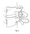
- FIG. 2is a lateral view of a facet joint reconstructed in accordance with the present invention.
- FIG. 3is a dorsal view of the facet joint shown in FIG. 2 ;
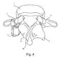
- FIG. 4is a perspective view of the implanted left inferior facet prosthesis shown in FIGS. 2 and 3 ;
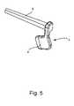
- FIG. 5is a perspective view of the left inferior facet prosthesis shown in FIGS. 2 and 3 ;
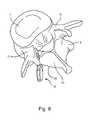
- FIG. 6is a cranial view of the implanted left superior facet prosthesis shown in FIGS. 2 and 3 ;
- FIG. 7is a perspective view of the left superior facet prosthesis shown in FIGS. 2 and 3 ;
- FIG. 8is a perspective view of an alternative implanted left inferior facet prosthesis
- FIG. 9is a perspective view of an alternative left inferior facet prosthesis
- FIG. 10is a lateral view of an alternative reconstructed facet joint
- FIG. 11is a dorsal view of an alternative reconstructed facet joint
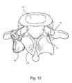
- FIG. 12is a perspective view of the implanted left inferior facet prosthesis shown in FIGS. 10 and 11 ;
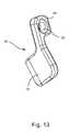
- FIG. 13is a perspective view of the alternative left inferior facet prosthesis shown in FIGS. 10 and 11 ;
- FIG. 14is a cranial view of the alternative implanted left superior facet prosthesis shown in FIGS. 10 and 11 ;
- FIG. 15is a perspective view of the alternative left superior facet prosthesis shown in FIGS. 10 and 11 ;
- FIG. 16is a perspective view of an alternative bearing surface for the superior facet prosthesis shown in FIG. 15 ;
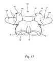
- FIG. 17is a dorsal view of a single intact vertebra
- FIG. 18is a lateral view of the same intact vertebra shown in FIG. 17 ;
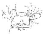
- FIG. 19is a dorsal view of the same vertebra of FIG. 17 and FIG. 18 , with a portion of the superior facet resected and a portion of the inferior facet resected;
- FIG. 20is a lateral view of the resected vertebra shown in FIG. 19 ;
- FIG. 21is a dorsal view of the same resected vertebra shown in FIG. 18 and FIG. 19 with a fixation element placed through the first superior resection surface and into the pedicle bone;
- FIG. 22is a dorsal view showing the resected vertebra, the fixation element, and a superior facet prosthesis
- FIG. 23is a dorsal view of the vertebra and the implant of FIG. 23 and also showing the addition of an inferior facet prosthesis;
- FIG. 24is a dorsal view of the implant and vertebra of FIG. 23 and also showing the addition of an enlarged head that has the shape of a locking nut;
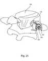
- FIG. 25is a perspective view of a vertebra with an assembled implant comprising a fixation element, superior facet prosthesis, and a locking nut;
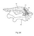
- FIG. 26is a perspective, cross-sectioned view of the same vertebra and implant of FIG. 25 with a cross section aligned with the axis of the fixation element;
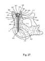
- FIG. 27is a cranial, cross-sectioned view of the vertebra and implant of FIG. 25 , with the section plane positioned as in FIG. 26 ;
- FIG. 28is a side view of embodiments A, B, C, D, E, and F of the fixation element, a cross-sectional view of each of embodiments A, B, C, D, E, and F, and a side view of the enlarged head in the shape of a locking nut;
- FIG. 28Ais a side view of embodiments G, H, I, J, K, and L of the fixation element with attached enlarged heads, and a cross-sectional view of each of embodiments G, H, I, J, K, and L;
- FIG. 29is a perspective view of a radially expanding fixation element in its unexpanded state
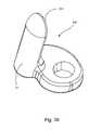
- FIG. 30is a side view and a bottom view of (i) an expanded radially expanding fixation element and (ii) an unexpanded radially expanding fixation element;
- FIG. 31is a perspective cross-sectional view of a vertebra and a facet implant showing a cross-pin torsionally and axially securing the fixation element;
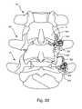
- FIG. 32is a dorsal view of a spinal section showing a top, middle, and bottom vertebra with unilateral facet replacements on the right side of the spine section, both between the top and middle vertebra, and between the middle and bottom vertebra;
- FIG. 33is a dorsal view of a spine section showing a superior hemiarthroplasty facet replacement between the top and the middle vertebra and unilateral replacement between the middle and the bottom vertebra;
- FIG. 34is a dorsal view of a spinal section showing an inferior facet hemiarthroplasty replacement between the top and the middle vertebra and a unilateral replacement on the right side between the middle and the bottom vertebra;
- FIG. 35is a dorsal view of a spinal section showing a unilateral replacement between the top and middle vertebrae on the right side, and an inferior facet hemiarthroplasty replacement between the middle and bottom vertebrae on the same side;
- FIG. 36is a dorsal view of a spinal section showing a unilateral replacement between the top and middle vertebrae on the right side and a superior facet hemiarthroplasty replacement on the right side between the middle and bottom vertebrae on the same side;
- FIG. 37is a spinal section of two vertebrae showing one inferior facet of the top vertebra and the adjoining superior facet of the bottom vertebra replaced by an articulating facet implant;
- FIG. 38is a perspective view of a curved superior facet prosthesis
- FIG. 39is a perspective view of a superior facet prosthesis with a bone ingrowth surface
- FIG. 40is a perspective view of an inferior facet prosthesis
- FIG. 41is a perspective view of an inferior facet prosthesis with a bone ingrowth surface
- FIG. 42is an exploded, perspective view illustrating the addition of a locking washer to the construction of the implant shown in FIG. 25 ;
- FIG. 43is a perspective view illustrating the implant of FIG. 25 with a locking washer fully installed
- FIG. 44is a perspective view of the locking washer shown in FIG. 42 ;
- FIG. 45is a perspective view of superior and inferior facet prostheses held against a vertebra by flexible fixation elements
- FIG. 46is a dorsal view of a bilateral inferior implant
- FIG. 47is perspective view of a vertebra with an alternative embodiment of a superior facet prosthesis fixed to the bone by one embodiment of a fixation element;
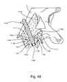
- FIG. 48is a perspective, cross-sectional view of the embodiment of the superior facet prosthesis and fixation element of FIG. 47 showing the semispherical shape of the resection and the approximately similarly semispherical shape of the apposition side of the superior facet prosthesis, as well as an angled resection and corresponding angled flat on the apposition side of the superior facet prosthesis in combination with the semispherical resection;
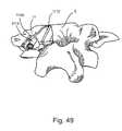
- FIG. 49is a perspective view of the resected vertebra without the superior facet prosthesis attached to the vertebra, in which the fixation element is installed in the vertebra;
- FIG. 50is a perspective view of the resected vertebra with the superior facet prosthesis attached to the vertebra, with the fixation element installed in the vertebra, but without the locking fastener shown in FIG. 47 ;
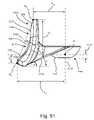
- FIG. 51is a top view of the superior facet prosthesis showing the semispherical shape of the bone apposition side in combination with the angled flat on the bone apposition side;
- FIG. 52is a rear view of the superior facet prosthesis showing the semispherical nut engaging surface on the top of the area that is design to connect to the fixation element and the locking nut, or the inferior prosthesis and the fixation element;
- FIG. 53Ais a rear view and a perspective view of a plurality of superior facet prostheses of a kit
- FIG. 53Bis a top view of an inferior facet prosthesis according to one embodiment of the invention.
- FIG. 53Cis a side view of the inferior facet prosthesis of FIG. 53B ;
- FIG. 53Dis a perspective view of a plurality of inferior facet prostheses of a kit
- FIG. 53Eis a perspective view showing how a superior facet prosthesis and an inferior facet prosthesis may fit together;
- FIG. 53Fis a dorsal view of an L5 superior facet prosthesis and an L4 inferior facet prosthesis fit on adjacent vertebrae to articulate against each other;
- FIG. 53Gis a posteriolateral view of the implants and vertebrae shown in FIG. 53F ;
- FIG. 53His a posteriolateral view showing a cross-section along a first plane cut through the articulation of the implants of FIG. 53F ;
- FIG. 53Iis a cephalad view showing a cross-section along a second plane cut through the articulation of the implants shown in FIG. 53F ;
- FIG. 54is a dorsal view of a bilateral inferior facet prosthesis system and a superior facet prosthesis in situ;
- FIG. 55is a perspective view of the bilateral inferior facet prosthesis system and the superior facet prosthesis of FIG. 54 ;
- FIG. 56is a lateral view of the bilateral inferior facet prosthesis system and superior facet prosthesis in situ
- FIG. 57is a cranial view of the bilateral inferior implant system in situ
- FIG. 58is a bottom view of the bilateral inferior facet prosthesis system in situ
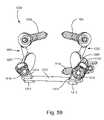
- FIG. 59is rear view of the bilateral inferior facet prosthesis system in isolation
- FIG. 60is a top view of the bilateral inferior facet prosthesis system in isolation
- FIG. 61is a bottom view of the bilateral inferior facet prosthesis system in isolation
- FIG. 62is a perspective view of the right inferior prosthesis
- FIG. 63is a perspective view of various ball-shaped members of inferior prostheses, the ball-shaped members having differing surface features, particularly circumferential grooves, longitudinal grooves, and knurling;
- FIG. 64is an end view of the ball-shaped members of FIG. 63 ;
- FIG. 65is a dorsal view of the bilateral inferior facet prosthesis system, in which castle nuts are attached to the left and right fixation elements.
- FIG. 1there is shown a perspective view of a superior vertebra 1 and an inferior vertebra 3 , with an intervertebral disc 2 located in between.
- the superior vertebra 1has superior facets 43 , inferior facets 6 , a posterior arch (or lamina) 35 and a spinous process 46 .
- the inferior vertebra 3has superior facets 7 , inferior facets 44 , a posterior arch (or lamina) 36 and a spinous process 45 .
- Each of the vertebrae 1 , 3also has a pair of pedicles 11 .
- FIG. 2in a lateral view, the left inferior facet 6 of the superior vertebra 1 shown in FIG. 1 has been resected and an inferior facet prosthesis 4 has been attached to the superior vertebra 1 .
- the left superior facet 7 of the inferior vertebra 3has been resected and a superior facet prosthesis 5 has been attached to the inferior vertebra 3 .
- FIG. 3illustrates a dorsal view of the elements shown in FIG. 2 .
- inferior facet prosthesis 4replicates the natural anatomy when compared to the contralateral inferior facet 6 of vertebra 1 .
- superior facet prosthesis 5replicates the natural anatomy when compared to the contralateral superior facet 7 of vertebra 3 .
- Neither the inferior facet prosthesis 4 nor the superior facet prosthesis 5rests on the lamina 35 .
- FIG. 4a perspective view of the superior vertebra 1 with implanted inferior facet prosthesis 4 is provided.
- a bone resection on the left side of the superior vertebra 1shown as a resection 31 , has removed the natural inferior facet 6 at the bony junction between the inferior facet 6 and the lamina 35 .
- any bone pain associated with a disease, such as osteoarthritis, or trauma of the left inferior facet 6will be eliminated as the involved bony tissue has been osteotomized.
- FIG. 5illustrates a perspective view of the inferior facet prosthesis 4 .
- a surface 8replicates the natural articular surface of the replaced inferior facet 6 .
- a post 9provides a mechanism that can be used to affix the inferior facet prosthesis 4 to the superior vertebra 1 .
- the post 9is implanted into the interior bone space of the left pedicle 11 on the superior vertebra 1 and may or may not extend into the vertebral body of superior vertebra 1 to provide additional stability.
- FIG. 6illustrates a cranial view of the inferior vertebra 3 with the implanted superior facet prosthesis 5 .
- a resection surface 32represents the bony junction between the natural superior facet 7 and the lamina 36 .
- FIG. 7illustrates a perspective view of the superior facet prosthesis 5 .
- a surface 38replicates the natural articular surface of the replaced superior facet 7 .
- the post 37provides a mechanism usable to affix the superior facet prosthesis 5 to the inferior vertebra 3 .
- the post 37is implanted into the interior bone space of the left pedicle 11 ( FIG. 6 ) on the inferior vertebra 3 and may or may not extend into the vertebral body of the inferior vertebra 3 to provide additional stability.
- the surface 8articulates against the surface 38 ( FIG. 7 ) to recreate the natural biomechanics of the spine motion segment made up of the superior vertebra 1 , the inferior vertebra 3 , and the intervertebral disc 2 .
- Neither the inferior facet prosthesis 4 nor the superior facet prosthesis 5rests on the lamina 35 or the lamina 36 , respectively.
- FIG. 8illustrates a perspective view of an alternative inferior facet prosthesis 10 that may be implanted into the interior bone space of the lamina 35 of the superior vertebra 1 .
- the interior bone spaceis accessed from the resection 31 .
- FIG. 9shows a perspective view of the alternative inferior facet prosthesis 10 , including a fin 13 that extends into the interior bone space of the 35 .
- a surface 12replicates the natural articular surface of the replaced facet.
- the surfaces of the post 9 ( FIG. 5 ), the post 37 ( FIG. 7 ), and the fin 13 ( FIG. 9 )may or may not include porous coatings to facilitate bone ingrowth to enhance the long-term fixation of the implant. Furthermore, such porous coatings may or may not include osteoinductive or osteoconductive substances to further enhance bone remodeling into the porous coating.
- implantrefers to any natural or man-made, fabricated or unfabricated device or group of devices that may be added to a human spine.
- An implantmay include one or more prostheses, one or more fixation devices, and/or other components.
- FIG. 10there is shown a lateral view of a superior vertebra 14 and an inferior vertebra 16 , with an intervertebral disc 15 located in between.
- the left inferior facet of the superior vertebra 14has been resected and an inferior facet prosthesis 18 has been attached to superior vertebra 14 via a screw fastener 17 .
- the left superior facet of the inferior vertebra 16has been resected and a superior facet prosthesis 19 has been attached to vertebra 16 via a screw fastener 17 .
- FIG. 11illustrates a dorsal view of the elements of FIG. 10 .
- inferior facet prosthesis 18replicates the natural anatomy when compared to the contralateral inferior facet 22 of the superior vertebra 14 .
- superior facet prosthesis 19replicates the natural anatomy when compared to the contralateral superior facet 21 of the inferior vertebra 16 .
- Neither the inferior facet prosthesis 18 nor the superior facet prosthesis 19rests on the lamina of the corresponding vertebra 14 or 16 .
- FIG. 12there is provided a perspective view of the superior vertebra 14 with the implanted inferior facet prosthesis 18 .
- a resection 34has removed the natural inferior facet at the bony junction between the inferior facet and the adjoining lamina. In this manner, any bone pain associated with a disease, such as osteoarthritis, or trauma of the natural inferior facet 22 will be eliminated inasmuch as the involved bony tissue has been osteotomized.
- FIG. 13illustrates a perspective view of the inferior facet prosthesis 18 .
- a surface 23replicates the natural articular surface of the replaced facet.
- a flange 25contacts the pedicle 11 ( FIG. 12 ) and a hole 24 receives the screw fastener 17 to attach the inferior facet prosthesis 18 to the superior vertebra 14 .
- FIG. 14illustrates a cranial view of the inferior vertebra 16 with the implanted superior facet prosthesis 19 .
- a resection surface 33represents the bony junction between the natural superior facet 21 ( FIG. 11 ) and the corresponding lamina.
- FIG. 15illustrates a perspective view of the superior facet prosthesis 19 .
- a surface 27replicates the natural articular surface of the replaced facet.
- a flange 39contacts the pedicle 11 ( FIG. 14 ) and hole 26 receives a screw fastener 17 to attach the superior facet prosthesis 19 to the inferior vertebra 16 .
- FIG. 16provides a perspective view of an alternative superior facet prosthesis 40 with a bearing surface 41 that mounts to substrate 42 .
- the bearing surface 41is a biocompatible polymeric material, such as ultra high molecular weight polyethylene.
- the bearing surfacecan be ceramic, such as zirconia or alumina.
- the substrateis a biocompatible metal alloy, such as an alloy of titanium, cobalt, and/or iron.
- the bearing surface 41may be formed separately from the remainder of the superior facet prosthesis 40 , so that the bearing surface 41 and the remainder form components that can be assembled as needed.
- a kit of differently-sized prosthesesmay include multiple bearing surfaces like the bearing surface 41 that may have different thicknesses, articulating surface shapes, material selections, and the like. Such a kit may also include other differently-sized components designed such that some subset of the components can be selected and assembled together to provide a prosthesis having the desired dimensions. Prosthesis kits will be shown and described in greater detail subsequently.
- FIG. 17is a dorsal view of the vertebra 100 .
- FIG. 18is a lateral view of the same vertebra 100 .
- the vertebra 100has posterior anatomy comprising left and right superior facets 43 on the superior, or top side in this view of the dorsal vertebra 100 , left and right inferior facets 6 on the inferior or bottom side of the posterior vertebra 100 , left and right transverse processes 105 extending laterally from the posterior portion of vertebra 100 , and left and right pedicles 11 .
- Each of the superior facets 43has a superior articulating surface 145 .
- the posterior portion of vertebra 100also has a posterior arch (or lamina) 35 , and a spinous process 46 that protrudes from the lamina 35 posteriorly, out of the page in FIG. 17 and to the left in FIG. 18 .
- the bony structure of the superior facets 43 and the inferior facets 6are intact, as it would be presented in a vertebra without significant tissue degeneration or remodeling resulting from facet joint disease.
- the vertebra 100is shown in FIG. 17 as a generally structurally healthy and intact vertebra, if the vertebra 100 were a diseased vertebra, the vertebra could exhibit signs of facet joint disease.
- the left superior facet 43 and the right superior facet 43 of the vertebra 100are symmetrical in FIG. 17 and FIG. 18 . But in the case of a vertebra 100 with only one diseased joint, the facet on the diseased side would likely be showing pathological signs of disease such as tissue degeneration or inflammation resulting in an asymmetrical structural comparison between the two facets.
- the facet diseasecould progress to a state in which the articular process of the facet is eroded or inflamed resulting in anatomic morphology that is unique to the pathology of a particular facet joint of an individual patient. This could present unusual facet morphology that could be different from what is shown in FIGS. 17 and 18 .
- the facet diseasecould eventually disable the biomechanics of a patient such that the facet joint is essentially non-articulating and immobile.
- one superior facet of a first vertebracould essentially be fused to one inferior facet of a second vertebra. Since the structural pathology of the diseased facet is variable, a surgeon may determine that the best bone apposition surface or foundation for securing a facet implant is a resected bone surface.
- FIG. 19 and FIG. 20which are dorsal and lateral views of the same vertebra shown in FIG. 17 and FIG. 18 after a portion of the right superior facet 43 and a portion of the right inferior facet 6 have been resected.
- the removal of a portion of the superior facet 43 by resectionresults in a superior facet resection 111 .
- the superior resection 111has two resulting faces, a first resection surface 112 and a second resection surface 113 .
- the inferior facet resectionresults in an inferior facet resection surface 121 .
- Tissue removal toolssuch as a bone burr, rasp, reamer, mill, saw, rounger, osteotome or similar tools designed to cut and remove bone tissue can be used to create these resection surfaces.
- the surgeonuses anatomic landmarks such as the pedicle 11 or transverse process 105 to align the tissue removal tools in such a way as to remove the portion of the facet necessary to provide a superior resection 111 that serves as a bone apposition surface or foundation to eventually support a superior facet prosthesis 300 , as shown in FIG. 22 .
- the left superior facet 43is shown intact in both FIG. 19 and FIG.
- the superior resection 111will vary in accordance with the structure of the tissue removal tool. In the embodiment shown in FIG. 19 and FIG. 20 , the first resection surface 112 and the second resection surface 113 are on approximately perpendicular planes. However, the geometry of the resection surfaces is a function of the patient anatomy, the pathology of the diseased tissue, the technique of the surgeon, and other factors such as the type of tissue removal tools used to prepare the resection.
- first resection surface 112will be formed in such a way that it will serve as a foundation to support the superior facet prosthesis 300 ( FIG. 22 ).
- the second resection surface 113 or other additional resection surfacesmay or may not be present.
- FIG. 19 and FIG. 20also show that a portion of the inferior facet 6 is resected by tissue removal instruments resulting in an inferior resection surface 121 .
- tissue removal instrumentsresulting in an inferior resection surface 121 .
- Such resectionis preferably effected so that resection is confined to the tissue of the inferior facet 6 and does not extend into the tissue of the posterior arch (or lamina) 35 .
- the left inferior facet 6is intact, while a portion of the right inferior facet 6 is resected resulting in the inferior resection surface 121 on the right side.
- the bone surrounding the inferior resection surface 121is contoured by tissue removal tools in a shape designed to cradle and support an inferior facet prosthesis 400 ( FIG. 23 ) on the medial side such that when the inferior facet prosthesis 400 is loaded on the lateral side it compresses against and is supported by the inferior resection surface 121 .
- inferior facet 6can be resected, and inferior facet prosthesis 400 sized and shaped, so that inferior facet prosthesis 400 does not engage the inferior resection surface 121 .
- FIG. 21is a dorsal view of the vertebra 100 with a fixation element 200 placed through the superior resection 111 and into the bone of the pedicle 11 to receive the superior facet prosthesis 300 ( FIG. 22 ).
- the fixation element 200is aligned and placed into the pedicle 11 , similar to how other pedicle screws for posterior stabilization involved with vertebrae fusion are placed in the pedicle 11 .
- a long guide wire(not shown), with a diameter sized to fit freely into a cannulation 211 (as also shown in FIG. 26 and FIG. 27 ) in the fixation element 200 , is placed through the first resection surface 112 and into the bone of the pedicle 11 .
- the alignment of the long guide wirecan be confirmed by x-ray.
- the fixation element 200is then guided over the guide wire and driven into the vertebra 100 by a driver (not shown) engaged with a drive feature 212 ( FIG. 21 ) on a proximal post 230 of the fixation element 200 .
- the fixation element 200is driven into the vertebra 100 until a connection feature 213 (e.g., a screw thread) is just above the first resection surface 112 .
- This connection feature 213is eventually used to secure the superior facet prosthesis 300 to the vertebra 100 .
- a long guide wire(not shown), with a diameter sized to fit freely into a cannulation in a bone preparation instrument (not shown) such as a tap, drill, broach or reamer, is placed through the first resection surface 112 and into the bone of the pedicle 11 .
- the alignment of the long guide wirecan be confirmed by x-ray.
- the bone preparation instrumentis then guided over the guide wire and driven into the bone of the pedicle 11 to prepare a cavity for the fixation element 200 .
- the guide wire and bone preparation instrumentare then removed and the fixation element 200 is guided into the prepared cavity in the pedicle 11 by a driver (not shown) engaged with the drive feature 212 on the proximal post 230 of the fixation element 200 .
- the fixation element 200is driven into the vertebra until a connection feature 213 (e.g., a screw thread) is just above the first resection surface 112 .
- This connection feature 213is eventually used to secure the superior facet prosthesis 300 to the vertebra 100 .
- the surgeonaligns the fixation element 200 with anatomic landmarks and simply drives the fixation element 200 through the first resected surface 112 and into the pedicle 11 .
- the fixation element 200is driven into the vertebra 100 until a connection feature 213 (e.g., a screw thread) is just above the first superior resection surface 112 .
- a dorsal viewillustrates a superior facet prosthesis 300 placed around the fixation element 200 .
- the superior facet prosthesis 300has a facet articulating component 320 that articulates against the inferior facet articulating surface of the vertebra above it.
- the facet articulating component 320is preferably formed in the general shape of a blade or wing ear.
- the superior facet prosthesis 300also has a bone apposition surface 322 that has been placed on the first resection surface 112 and an opening 324 in a flange 323 that surrounds the fixation element 200 .
- the superior facet articulating component 320has an articulating surface 321 generally adjacent to the flange 323 that is oriented in a direction that faces approximately the same direction that the original anatomic superior articulating surface 145 faced prior to resection.
- This orientation of the articulating surface 321allows the superior facet prosthesis 300 to function as either a hemiarthroplasty implant and articulate against a natural anatomic inferior facet 6 or act as a portion of a unilateral prosthesis and articulate against an inferior facet prosthesis 400 on the vertebra superior (cephalad) to it. No portion of superior facet prosthesis 300 rests on the lamina of the vertebra 100 .
- a “unilateral prosthesis”is a prosthesis in which both facets of only one of the facet joints between adjacent vertebrae are replaced by prostheses.
- a “hemiarthroplasty”is a type of arthroplasty in which one side of an articulating joint surface is replaced with an artificial implant.
- FIG. 23is a dorsal view showing the addition of the inferior facet prosthesis 400 to the construct described in FIG. 22 .
- the inferior facet prosthesis 400generally has a shape similar to a longitudinal rod that is curved to match the contour of the inferior resection 121 ( FIGS. 19 and 20 ).
- the inferior facet prosthesis 400has an opening 410 through its superior end 420 that is shaped to surround the portion of the fixation element 200 that protrudes from the first resection surface 112 .
- the inferior facet prosthesis 400is placed over the superior facet prosthesis 300 .
- the order of the placement of the prostheses 300 , 400can be reversed such that the inferior prosthesis 400 is placed on the fixation element 200 first, followed by the superior prosthesis 300 .
- the appropriate (superior or inferior) facet prosthesis 300 or 400is placed on the fixation element 200 without the other (inferior or superior) facet prosthesis 300 or 400 .
- the various components of the implantare modular, many combinations of configurations and implant size, structure and shapes are feasible.
- the inferior facet prosthesis 400may need to be larger than expected to conform to a particularly unusual or exceptionally large morphology of the inferior resection surface 121 , and the superior facet prosthesis 300 may need to have an unusual angle to its articulating surface 321 to conform to particular anatomic constraints.
- the modularity of the systemallows for the surgeon to assemble an implant specifically designed to match the patient's anatomic structures during the surgery. This flexibility of a modular implant design allows the implant manufacturer to accommodate a large variation in anatomic structures with a limited selection of implant component sizes, shapes, and material types.
- fixation implantssuch as the fixation element 200 are fabricated from biocompatible metals or alloys that provide sufficient strength and fatigue properties, such as cobalt chrome alloys, titanium and titanium alloys, and stainless steels.
- the fixation element 200may be fabricated from ceramics, polymers, or biological materials such as allograft bone, composites, or other biocompatible structural materials.
- the superior facet prosthesis 300 and the inferior facet prosthesis 400may be fabricated from metals, alloys, ceramics, polymers, biological materials, composites, or other biocompatible structural materials.
- FIG. 24a dorsal view illustrates the addition of an enlarged head 500 to the fixation element 200 .
- the enlarged head 500is tightened down to force the prostheses 300 , 400 against the bone to stabilize them.
- the enlarged head 500 shown in FIG. 24has a hexagonal geometry on its external surface that is shaped to accept a driver (not shown) that is used to force an internal connection feature 520 (e.g., a screw thread) of the enlarged head 500 onto the connection feature 213 of the fixation element 200 .
- the enlarged head 500is provided with a threaded connection feature 520 and is driven onto the fixation element 200 by turning the enlarged head 500 and allowing the threads to drive all components of the implant between the enlarged head 500 and the first resection surface 112 against the bone at or near the resection surface 112 .
- FIG. 25is a perspective posterior view of the assembly of the fixation element 200 , the superior facet prosthesis 300 , and the enlarged head 500 .
- the enlarged head 500has been placed on the first resection surface 112 .
- FIG. 26is a perspective, cross-sectioned view of the same construct shown in FIG. 25 .
- the superior facet prosthesis 300 , the enlarged head 500 , the fixation element 200 , and the vertebra 100have been cut by a cross-sectioning plane 150 placed along an axis that passes through the center of the fixation element 200 .
- the cross-section plane 150is shown for visualization purposes to illustrate, using a cross-sectioned view, how the vertebra 100 , fixation element 200 , superior facet prosthesis 300 and the enlarged head 500 engage each other. In actual surgery, it is highly unlikely that a surgeon would make a cut as illustrated by the cross-section 150 shown in FIG. 26 .
- FIG. 27is a cranial, section view of the vertebra 100 and the implant, wherein the cross-section plane 150 is oriented to face the viewer.
- the fixation element 200is in the vertebra 100 .
- the embodiment of the fixation element 200 in FIG. 27comprises a distal end 220 that is shaped to guide the fixation element 200 into bone tissue, a bone stabilizing portion 210 adjacent to the distal end, a shaft portion 240 adjacent to the bone stabilizing portion 210 , a connection feature 213 adjacent to the shaft portion 240 , and a drive feature 212 .
- the distal end 220 shown in FIG. 27has a frusto-conical shape that allows the fixation element 200 to be driven or guided into the vertebra 100 .
- the distal end 220could be shaped in the form of a spade tip, trochar tip, or twist drill tip to assist in the guidance of the fixation element 200 in the vertebra 100 .
- the fixation element 200may also have a cutting flute (not shown) formed in the distal end 220 to help remove bone tissue and accommodate the guidance of the fixation element 200 in the vertebra 100 .
- the bone stabilizing portion 210helps to secure the fixation element 200 to the vertebra 100 .
- the bone stabilizing portion 210can include various features designed to anchor into bone such as threads, ribs, grooves, slots, fins, barbs, splines, bone ingrowth surfaces, roughened surfaces, or any geometric feature that helps to engage the fixation element 200 with the bone tissue to help stabilize the fixation element 200 .
- the bone stabilizing portion 210has a unitary continuous bone thread 231 .
- other types of threadssuch as multiple lead threads, variable pitched thread, non-uniform pitch thread, buttress thread, or other thread forms used on bone screws may be used. Because FIG. 27 is a cross-sectional view, the full length of the cannulation 211 is seen passing from the distal end 220 of the fixation element 200 to the proximal post 230 of the fixation element 200 .
- the drive feature 212 in the embodiment shown in FIG. 27is an internal hex. However, any shape of drive feature 212 that transmits the loads necessary to drive the fixation element 200 into the vertebra 100 can be formed on the proximal post 230 of the fixation element 200 .
- the depth of the drive feature 212 formed in the proximal post 230 of the fixation element 200is seen in the cross-sectional view of FIG. 27 .
- the drive feature 212may be an internal drive feature such as the hex socket shown in this embodiment, or an external drive feature with geometry on the periphery of the proximal post 230 of the fixation element 200 that engages with a corresponding internal drive feature on a driver tool (not shown).
- the depth of the drive feature 212is slightly longer than its cross-section is wide. This depth can be adjusted based on the material properties of the fixation element 200 and the drive tool (not shown).
- the fixation element 200is fabricated from biocompatible base materials that provide the necessary structural rigidity and strength.
- base materialsthat may be used in the construction of the fixation element 200 include titanium, titanium alloys, cobalt-chrome alloys, stainless steel alloys, zirconium alloys, other biocompatible metal materials, biocompatible ceramics, biocompatible composites, and biocompatible polymers.
- the fixation element 200may also have surface materials formed on the base material that provide material properties specific to a particular portion of the fixation element 200 .
- the bone stabilization portion 210could be coated with materials that allow for improved bone ingrowth into the implant surface such as a hydroxylapatite, bioceramic, Bioglass®, or other calcium phosphate derived material.
- the tribological bearing properties of the material in the areas that the fixation element 200 interfaces with other artificial elementsmay be improved by applying surface hardening techniques to the material of the fixation element 200 in these areas.
- Surface hardening techniques known in the materials science and materials engineering artssuch as anodizing, ion implantation, and other techniques could be applied to these isolated areas.
- connection feature 213is formed on the portion of the fixation element 200 that protrudes from the first resection surface 112 .
- This connection feature 213is designed to connect the enlarged head 500 to the fixation element 200 .
- threads 260are on the external surface of this proximal section of the fixation element 200 . These threads 260 engage with the threads of the internal connection feature 520 ( FIG. 27 ) of the enlarged head 500 .
- connection feature 213 in this embodimentis threaded
- other mechanical locking featurescapable of locking the fixation element 200 and the enlarged head 500 together, such as press fit, taper fit, bonding fit by cement or glue, interference fit, expansion fit and mechanical interlocking fit such as a bayonet connection, can be used as the connection feature 213 .
- a corresponding constructionmay then be used as connection feature 520 of the enlarged head 500 .
- FIG. 27Also shown in FIG. 27 is a cross-sectional view of the superior facet prosthesis 300 .
- This embodiment of the superior facet prosthesis 300has a flange 323 that has an opening 324 that receives the fixation element 200 .
- the flange 323is positioned such that its bone apposition surface 322 makes contact with the first resection surface 112 .
- other embodiments of the superior facet prosthesis 300have structures (e.g., spikes) that protrude into the first resection surface 112 to help resist torsion and other anatomic loads.
- the articulating component 320Protruding from the flange 323 at a given angle ⁇ , and a given distance X from the opening 324 , is the articulating component 320 .
- the articulating surface 321 of the facet articulating component 320replicates the natural articular surface of the replaced facet.
- the enlarged head 500in this embodiment has an internal connection feature 520 and a hexagonal shaped external drive feature 510 that is used to drive the enlarged head 500 over the fixation element 200 and against the superior facet prosthesis 300 .
- the specific shape of the external drive feature 510is dependent on the mating shape of the driver (not shown).
- FIG. 28side and cross-sectional views illustrate six different embodiments of fixation elements, which are labeled A, B, C, D, E, and F.
- the figureshows a side view of each fixation element embodiment and a cross-sectional view of each embodiment to the right of the respective side view.
- To the left of the six embodimentsis a representative enlarged head 500 .
- Embodiment Ais the threaded fixation element 200 embodiment shown in FIGS. 26 and 27 and described above.
- Embodiments B through Eare various designs of fixation elements with non-circular cross-sections.
- Embodiment Bis a four rib cruciate design with four longitudinal fins 285 configured to resist torsion when the fixation element 200 is in the vertebra 100 .
- Embodiment Cis an oval shaped cross-section design that is wider in the first direction 286 than the second direction 287 to resist torsion. If the width in the first direction 286 is equal to the width in the second direction 287 , the cross-section shape becomes more of a circle and bone stabilization portion 210 becomes more of a press-fit peg.
- Embodiment Dis a square cross-section design with four approximately perpendicular sides 288 . The corners 289 of the sides 288 help to resist torsion.
- Embodiment Eis a triangular cross-section design with three sides 291 to resist torsion.
- Embodiment Fis an anchor-like design that is driven into the vertebra, with the wire arches or barbs 290 being compressed against the host bone and applying a radial expansion force so as to lock the structure to the bone.
- FIG. 28Aside and cross-sectional views illustrate six more different embodiments of fixation elements, which are labeled G, H, I, J, K, and L.
- FIG. 28Ashows a side view of each fixation element embodiment and a cross-sectional view of each embodiment to the right of the respective side view.
- Each embodimenthas an attached or integrally formed enlarged head 500 ′.
- Embodiment Gis similar to the threaded fixation element 200 embodiment shown in FIGS. 10 , 11 , 12 and 24 and described above.
- Embodiments H through Kare various designs of fixation elements with non-circular cross-sections.
- Embodiment His a four rib cruciate design with four longitudinal fins 285 configured to resist torsion when the fixation element is in the vertebra 100 .
- Embodiment Iis an oval shaped cross-section design that is wider in a first direction 286 than in a second direction 287 to resist torsion. If the width in the first direction 286 is equal to the width in the second direction 287 , the cross-section shape becomes more of a circle and the bone stabilization portion 210 becomes more of a press-fit peg.
- Embodiment Jis a square cross-section design with four approximately perpendicular sides 288 . The corners 289 of the sides 288 help to resist torsion.
- Embodiment Kis a triangular cross-section design with three sides 291 to resist torsion.
- Embodiment Lis an anchor-like design that is similar to Embodiment F in FIG. 28 , but with an attached or integrally formed enlarged head 500 ′. As embodiment L is driven into the vertebra, wire arches or barbs 290 are compressed and apply radial expansion force against the wall of the prepared bone and into the pedicle 11 , resulting in a locking anchor.
- FIG. 29is a perspective view of a radially expanding fixation element 600 .
- the radially expanding fixation element 600comprises two main elements, an expansion sleeve 620 and a central element 610 that is inside of the expansion sleeve 620 .
- the radially expanding fixation element 600is placed into the vertebra 100 and then the central element 610 is drawn outward relative to the expansion sleeve 620 resulting in radial expansion of the fixation element 600 . This is shown in FIG. 30 .
- FIG. 30side and bottom views illustrate the fixation element 600 of FIG. 29 .
- a proximal post 630 of the central element 610is pulled axially along its longitudinal axis, and the expansion sleeve is held axially in the bone by compression fit, talons 621 on the expansion sleeve 620 are radially expanded outward by a mandrel 660 on the central element 610 .
- the talons or fingers 621provide both torsional and axial stability to the radially expanding fixation element 600 .
- Thisprovides a secure fixation element for fixation of the remaining implant components.
- expansion of the fixation element 600may cause the fixation element 600 to center itself within the pedicle 11 .
- FIG. 31is a perspective, cross-sectional view of a cross-pin element 700 engaged with the fixation element 200 to help secure the fixation element 200 both torsionally and axially.
- the cross-pin element 700is columnar in shape having a distal end 710 , a midsection 730 (with a length along its longitudinal axis that is longer than its transverse cross-sectional width), and a proximal post 720 .
- the distal end 710is shaped to penetrate through bone tissue and into a cross hole 280 formed in the fixation element 200 .
- Instrumentation(not shown) is used to align the cross-pin element 700 with the cross-hole 280 via fixation of the instrumentation to the drive feature 212 or the cannulation 211 on the fixation element 200 and alignment of the direction of insertion of the cross-pin element 700 with the cross-hole 280 .
- fixation element 200described above and shown in FIG. 28 through FIG. 31 function in conjunction with the enlarged head 500 to hold the inferior facet prosthesis 400 and/or the superior facet prosthesis 300 to their respective resection surfaces 112 , 113 , and/or 121 .
- FIGS. 32 through 37Various combinations of this modular implant will be described below and shown in FIGS. 32 through 37 .
- FIGS. 32 through 37illustrate the use of the fixation element 200 and the enlarged head 500 as the mechanism for securing the prostheses 300 , 400 to the vertebra 100
- other clamping devicessuch as the screw fastener 17 ( FIG. 10 ) may be used to mount the prostheses 300 , 400 to the bone.
- 10 through 12may pass through either the opening 324 ( FIG. 22 ) in the superior facet prosthesis 300 or the opening 410 ( FIG. 23 ) in the inferior facet prosthesis 400 or through both of these openings 324 , 410 .
- the head of the screw fastener 17acts as the securing mechanism by pressing the inferior facet prosthesis 400 and the superior facet prosthesis 300 against their respective resection surfaces 112 , 113 , and/or 121 .
- FIGS. 32 through 37demonstrate different combinations of assemblies of facet replacement prostheses.
- the basic components of the prosthesisare the fixation element 200 , the superior facet prosthesis 300 , the inferior facet prosthesis 400 , and the enlarged head 500 .
- a screw fastener 17can replace the fixation element 200 and the enlarged head 500 .
- a dorsal viewillustrates three sequential layers of vertebrae.
- a top vertebra 101is above a middle vertebra 102
- the middle vertebra 102is above a bottom vertebra 103 .
- Portions of some of the facets on the right side of the vertebraeare replaced by prostheses.
- an inferior facet prosthesis 401is articulating against a superior facet prosthesis 302 to form an artificial unilateral joint.
- the inferior facet of the middle vertebra 102is replaced by an inferior facet prosthesis 402 and the superior facet of the bottom vertebra 103 is replaced by superior facet prosthesis 303 .
- FIG. 32demonstrates the difference in shape of the inferior facet prosthesis 401 that is implanted around the fixation element 201 without a superior facet prosthesis 300 and an inferior facet prosthesis 402 that is implanted around a fixation element 202 and over a superior facet prosthesis 302 .
- the opening 410 (not visible) of the inferior facet prosthesis 401 on the top vertebra 101 in this assemblyis offset more laterally than the opening 410 (not visible) in the inferior facet prosthesis 402 for the middle vertebra 102 . This is because the fixation element 201 is implanted more laterally on the top vertebra 101 to preserve more of the superior facet since it is not replaced by a prosthesis at this level.
- a dorsal viewillustrates the top vertebra 101 in intact form, without resection of the facets. Portions of both the superior and inferior facets on the right side of the middle vertebra 102 are replaced by a superior facet prosthesis 302 and an inferior facet prosthesis 402 . Only the right superior facet of the bottom vertebra 103 is replaced (i.e., by a superior facet prosthesis 303 ) in FIG. 33 . Thus, a hemiarthroplasty replacement has been performed on the right facet joint between the top vertebra 101 and the middle vertebra 102 and a unilateral replacement has been performed between the middle vertebra 102 and the bottom vertebra 103 .
- the assembly shown in FIG. 33demonstrates how the superior facet prosthesis 302 can articulate against the natural inferior facet 6 and the superior facet prosthesis 303 can articulate against the inferior facet prosthesis 402 .
- FIG. 34is a dorsal view illustrating how the inferior facet prosthesis 401 can articulate against the natural superior facet 43 , or the inferior facet prosthesis 402 can articulate against the superior facet prosthesis 303 .
- the right facet joint between the top vertebra 101 and the middle vertebra 102is a hemiarthroplasty replacement with the inferior facet replaced by the inferior facet prosthesis 401 .
- the right facet joint between the middle vertebra 102 and the bottom vertebra 103is a unilateral replacement with the inferior facet replaced by the inferior facet prosthesis 402 and the superior facet of the bottom vertebra 103 replaced by the superior facet prosthesis 303 .
- a dorsal viewshows another example of how the superior facet prosthesis 303 can articulate against the natural inferior facet 6 or the superior facet prosthesis 302 can articulate against the inferior facet prosthesis 401 .
- the right side between the top vertebra 101 and the middle vertebra 102is a unilateral replacement and the right side between the middle vertebra 102 and the bottom vertebra 103 is a hemiarthroplasty replacement.
- a dorsal viewshows another example of how the inferior facet prosthesis 402 can articulate against the natural superior facet 43 , or the inferior facet prosthesis 401 can articulate against the superior facet prosthesis 302 .
- the right facet joint between the top vertebra 101 and the middle vertebra 102is a unilateral replacement with the inferior facet of the top vertebra 101 replaced by the inferior facet prosthesis 401 and the superior facet of the middle vertebra 102 replaced by the superior facet prosthesis 302 .
- the right facet joint between the middle vertebra 102 and the bottom vertebra 103is a hemiarthroplasty replacement with the inferior facet replaced by the inferior facet prosthesis 402 .
- a dorsal viewillustrates only one level, that between the middle vertebra 102 and the bottom vertebra 103 , being replaced on the right side.
- the right facet joint between the middle vertebra 102 and the bottom vertebra 103is a unilateral replacement with the inferior facet of the middle vertebra 102 replaced by the inferior facet prosthesis 402 and the superior facet of the bottom vertebra 103 replaced by the superior facet prosthesis 303 .
- FIG. 38 and FIG. 39show two embodiments of the superior facet prosthesis.
- a perspective viewillustrates an embodiment in which a curved superior facet prosthesis 305 with a curved articulating component 330 has a curved articulating surface 331 .
- This curved articulating surface 331allows for a more distributed contact load between an inferior facet prosthesis, such as the inferior facet prosthesis 400 of FIG. 23 , and the curved articulating surface 331 . This allows slightly more flexibility in the position that the surgeon places the curved superior facet prosthesis 305 than the superior facet prosthesis 300 previously described.
- the articulating surface 321 of the superior facet prosthesis 300 previously describedis relatively flat.
- the articulating surface 331 of the curved superior facet prosthesis 305is curved. Since the bearing portion of the inferior facet prosthesis 400 is columnar, the two prosthesis can be aligned on a slight mismatch and make more of an anatomic contact if the articulated surface is curved as in FIG. 38 .
- a perspective viewillustrates a bone ingrowth feature 390 on a superior facet prosthesis 306 .
- the bone ingrowth feature 390can be any surface that allows bone to grow into the implant between the first resection surface 112 of the vertebra 100 and the apposition surface 322 of the implant.
- Examples of bone ingrowth features 390include porous coating of beads or meshes, electrochemically etched shapes and porous pads pressed onto the implant surface made from tantalum, titanium, cobalt chrome alloys and/or other biocompatible material such as hydroxylapatite or calcium phosphate ceramics.
- a perspective viewshows the inferior facet prosthesis 400 , which is formed in the general shape of a finger or talon. More particularly, the inferior facet prosthesis 400 is formed with a flange 420 on its superior side shaped to fit between the enlarged head 500 and either the superior facet prosthesis 300 or the first resection surface 112 .
- the flange 420has an opening 410 that is dimensioned to allow the inferior facet prosthesis 400 to fit over the proximal post 230 of the fixation element 200 and around the shaft portion 240 of the fixation element 200 .
- the inferior facet prosthesis 400also has an inferior portion 450 on the opposite side of the flange 420 that has a bone apposition side 440 that is shaped to contact the surface of the inferior facet resection surface 121 ( FIG. 19 ) and a joint articulation side 430 that is shaped to articulate against a natural or prosthetic superior facet.
- a perspective viewshows an inferior facet prosthesis 460 also formed in the general shape of a finger or talon.
- the inferior facet prosthesis 460is formed with a superior end 420 having an opening 410 that is dimensioned and shaped to accept the fixation element 200 .
- the inferior facet prosthesis 460is generally columnar in shape, having a curved length designed to conform to the prepared anatomy of the vertebra 100 .
- the inferior facet prosthesis 460 of FIG. 41has an inferior portion 470 , which is shown opposite the superior end 420 , and slightly medially offset from the superior end 420 .
- the inferior facet prosthesis 460 of FIG. 41has a bone ingrowth surface 441 and a joint articulating side 430 on its inferior end 470 .
- the bone ingrowth surface 441is a textured structure that permits bone cells to grow into the implant surface.
- the shape of the bone ingrowth surface 441can be a uniform textured surface as shown in FIG.
- the bone ingrowth surface 441is shaped to mate with the inferior resected bone surface 121 shown in FIG. 19 and FIG. 20 .
- FIG. 42shows an exploded, perspective view of the vertebra 100 with the superior facet prosthesis 300 installed.
- An additional locking washer 800is used to assist in stabilizing the attachment of the superior facet prosthesis 300 to the first resection surface 112 .
- the construction of the implant assembly shown in FIG. 42is similar to that of the assembly shown in FIG. 25 with the addition of the locking washer 800 that is placed over and around the proximal post 230 of the fixation element 200 .
- FIG. 43a perspective view shows the same implant of FIG. 42 with the enlarged head 500 locked onto the fixation element 200 and pushing the locking washer 800 against the superior facet prosthesis 300 and into the bone tissue. This added bone penetration of the locking washer 800 helps to fix the superior prosthesis 300 such that the entire assembly is more mechanically stable with respect to the vertebra 100 .
- FIG. 43shows a further step in the assembly of the implant construct described in FIG. 42 .
- the locking washer 800is secured over the fixation element 200 and into the bone tissue by the enlarged head 500 .
- the locking washer 800can alternatively be used to mechanically secure the inferior facet prosthesis 400 , or the combination of the inferior facet prosthesis 400 and the superior facet prosthesis 300 .
- the locking washer 800is placed over the superior facet prosthesis 300 .
- the locking washer 800may be placed under the superior facet prosthesis 300 , under the inferior facet prosthesis 400 and the superior facet prosthesis 300 , or between the superior facet prosthesis 300 and the inferior facet prosthesis 400 to stabilize the implant construct.
- FIG. 44shows a perspective view of the locking washer 800 .
- the locking washer 800has a body 805 with an opening 810 that is dimensioned to fit over the proximal post 230 of the fixation element 200 .
- the locking washer 800also has an anti-rotation feature 820 that mates with either the superior facet prosthesis 300 or the inferior facet prosthesis 400 or a combination of both the inferior facet prosthesis 400 and the superior facet prosthesis 400 .
- the anti-rotation feature 820 shown in this embodimentis a flat surface, however, any feature that would rotationally constrain the locking washer 800 to the other components of the implant (such as a tab, groove, taper or other geometric shape) can be formed on the locking washer 800 as an anti-rotation feature.
- the locking washer 800also has prongs 830 that pass into the bone tissue of the vertebra 100 to help stabilize the implant construct.
- the prongs 830 in this embodiment of the locking washer 800are elongated protrusions that taper to a tissue penetration tip 840 .
- the prongshave sidewalls 850 that provide a surface to resist torsion once the locking washer 800 penetrates the bone tissue.
- the prongs 830may also be simple spikes that are either symmetrical or asymmetrical in cross-section that protrude from the locking washer body 805 .
- the shape and length of the locking washer prongs 830are dependent on how the locking washer 800 is used.
- the prongs 830 of the locking washer 800 that holds only one of the inferior facet prosthesis 400 or the superior facet prosthesis 300 to the vertebra 100may be shorter than prongs of a locking washer that holds both the inferior facet prosthesis 400 and the superior facet prosthesis 300 to the vertebra 100 .
- FIG. 45shows a perspective view of the superior facet prosthesis 300 and inferior facet prosthesis 400 held to the vertebra 100 by an adjunctive flexible fixation element 900 and a secondary flexible fixation element 910 .
- These flexible fixation elements 900 and/or 910may be made from such constructs as suture, braided cable, wire, ribbon, and/or other constructs that have longer lengths than cross-sections and withstand larger loads in tension than in compression.
- the flexible fixation elements 900 and/or 910may be manufactured from biocompatible metals, alloys such as cobalt chrome alloys, titanium alloys, stainless steel alloys, polymers, bioabsorbable materials, composites, or other materials that are biocompatible and can be formed into a flexible element structure 900 and/or 910 such as those shown in FIG. 45 .
- the adjunctive flexible element 900 shown in FIG. 45is shown attached to and securing the elongated head 500 .
- a flexible element attachment portion 580(e.g., including an opening) mates the flexible element 900 to the elongated head.
- adjunctive flexible fixation element 900may alternatively or additionally be attached to the fixation element 200 , the superior facet prosthesis 300 , the inferior facet prosthesis 400 or any combination of the above listed elements.
- a flexible fixation attachment portion 480e.g., including an opening
- the flexible fixation elements 900 and/or 910may be secured to the vertebra 100 by physically wrapping them around anatomic features such as the posterior arch 35 , the spinous process 46 , transverse process 105 , or a combination of these anatomic features.
- the flexible element 900 and the secondary flexible element 910may also be secured to the vertebra 100 by bone anchors such as anchors designed to anchor flexible fixation elements (such as suture, not shown) to bone.
- bone anchorssuch as anchors designed to anchor flexible fixation elements (such as suture, not shown) to bone.
- Suture anchorssuch as threaded suture anchors, barbed suture anchors, toggle suture anchors or any other means of anchoring a flexible fixation element to bone may be used to anchor the flexible fixation element 900 and/or the secondary flexible fixation element 910 to the vertebra 100 .
- FIG. 46is a dorsal view of a bilateral inferior facet prosthesis 1000 .
- the bilateral inferior facet prosthesis 1000is a one-piece inferior facet prosthesis that has both a right inferior side 1040 and a left inferior side 1020 connected by a stabilizing bar 1010 . Both the right inferior side 1040 and the left inferior side 1020 are designed to fix to the top vertebra 101 at the respective inferior resection surface 121 ( FIG. 19 ) and at the first resection surface 112 .
- the bilateral inferior facet prosthesis 1000allows replacement of both the left and the right inferior facets.
- the bilateral inferior facet prosthesis 1000is placed over the left and right fixation elements 200 which extend into the bone of the top vertebra 101 . In the embodiment shown in FIG.
- the right inferior side 1040is articulating against the right superior facet prosthesis 300 attached to the bottom vertebra 102 .
- the left inferior side 1020is articulating against the left natural superior facet 43 of the bottom vertebra 102 .
- the stabilizing bar 1010 of the bilateral inferior prosthesis 1000is designed to stabilize the left side 1020 and the right side 1040 so that they are secure.
- FIG. 47illustrates a perspective view of a superior facet prosthesis 1100 coupled to the vertebra 3 .
- the superior facet prosthesis 1100has a bone apposition surface (not shown) that has been placed on a first resection surface 1112 and an opening (not shown) in a flange 1116 that surrounds a fixation element 1110 , and coupled thereto by a locking fastener such as a castle nut 1114 or the like.
- the superior facet prosthesis 1100has a superior facet articulating component 1120 with an articulating surface 1122 generally adjacent to the flange 1116 .
- the articulating surface 1122is oriented in a direction that faces approximately the same direction that the original anatomic superior articulating surface faced prior to resection.
- This orientation of the articulating surface 1122allows the superior facet prosthesis 1100 to function as either a hemiarthroplasty implant by articulating against a natural anatomic inferior facet 6 or as a unilateral prosthesis by articulating against an inferior facet prosthesis on the vertebra superior (cephalad) to it, such as the inferior facet prosthesis 4 shown in FIG. 5 , the inferior facet prostheses 10 shown in FIGS. 8 and 9 , and the inferior facet prosthesis 400 shown in FIG. 40 , as well as those described below.
- the facet articulating component 1120is preferably formed in the general shape of a blade or wing ear, wherein the articulating surface 1122 has a concave shape. In the embodiment shown, the articulating surface 1122 curves from an orientation generally perpendicular to the flange 1116 towards an orientation generally parallel to the flange 1116 from a distal end 1124 thereof to a proximal end 1126 thereof.
- the concave shape of the articulating surface 1122provides more tolerance for a miss-match with the natural anatomic inferior facet 6 or with the inferior facet prosthesis 4 on the vertebra superior to it.
- the clearance between the concave shape of the articulating surface 1122 and the adjacent inferior facet 6 or inferior facet prosthesis 4increases as the patient bends forward (flexion) and decreases as the patient bends backward (extension).
- the patienthas more facet movement allowing for more torsion (twisting) and lateral bending (side to side movement) than in a neutral stance.
- the articulating membersare more constrained in torsion and lateral bending. This mimics the natural anatomic constraints of the spinal facets.
- FIG. 48is a perspective view of the same construct shown in FIG. 47 , but with the implants and the vertebra 3 cut by a cross-sectioning plane 1130 placed along an axis that passes through the center of the fixation element 1110 .
- the cross-section plane 1130 shown cutting through the vertebra 3 and the implant of FIG. 47is shown for visualization purposes to illustrate, using a cross-sectioned view, how the vertebra 3 , fixation element 1110 , and superior facet prosthesis 1100 engage each other.
- the fixation element 1110provides a mechanism that affixes the superior facet prosthesis 1100 to vertebra 3 .
- Fixation element 1110is implanted into the interior bone space of the left pedicle 11 ( FIG. 6 ) on the vertebra 3 and may or may not extend into the vertebral body of vertebra 3 to provide additional stability.
- the fixation element 1110can take the form of a screw (as shown), or any of the devices shown in FIGS. 28-30 .
- the fixation element 1110has a drive feature 1140 , which is an internal hex in the embodiment shown in FIG. 48 . However, any shape of drive feature that transmits the loads necessary to drive the fixation element 1110 into the vertebra 3 can be formed on a proximal post 1142 of the fixation element 1110 .
- the depth of the drive feature 1140 formed in the proximal post 1142 of the fixation element 1110is seen in the cross-sectional view of FIG. 48 .
- the drive feature 1140may be an internal drive feature such as the hex socket shown in this embodiment, or an external drive feature with geometry on the periphery of the proximal post 1142 of the fixation element 1110 that engages with a corresponding internal drive feature on a driver tool (not shown).
- the flange 1116 of the superior facet prosthesis 1100is secured to the fixation element 1110 by the castle nut 1114 or the like.
- the flange 1116 of the superior facet prosthesis 1100includes a coupling portion 1144 having a generally semispherical bone engaging surface 1150 on the apposition side of the superior facet prosthesis 1100 that engages a corresponding semispherical resection 1146 in the bone bed of the pedicle of vertebra 3 .
- the term “semispherical”relates to a surface that includes some sectorial portion of a sphere, which may be less than a hemisphere.
- a semispherical surfacemay be concave or convex.
- a surface that is semispherical or generally semisphericalmay have some deviations from a precise semispherical shape.
- the semispherical resection 1146may be said to be “inversely shaped” with respect to the coupling portion because the semispherical resection 1146 has a generally concave surface that matches the generally convex surface of the coupling portion 1144 .
- the coupling portion 1144 and the semispherical resection 1146are semispherical in the embodiment of FIGS. 47 and 48 , in alternative embodiments, they may have a variety of other matched shapes, including three-dimensional parabolas, ellipsoids, and other regularly or irregularly curved or flat-sided shapes.
- the coupling portion 1144is convex and the semispherical resection 1146 is concave in the embodiment of FIGS. 47 and 48
- the shapesmay be reversed so that a coupling portion is concave and a resection is convex.
- the coupling portion 1144is integrally formed with the articulating surface 1122 of the superior facet articulating component 1120 .
- the coupling portion 1144may be said to be “attached to” the articulating surface 1122 because in this application, the term “attached” is used broadly to include parts that are integrally formed with each other as well as parts that are formed separately and subsequently coupled together.
- the semispherical resection 1146 in the bone bedallows for less transverse process to be resected (vs. a flat bone bed resection).
- the semipherical resection 1146 in the bone bedalso allows for more stable support of the superior facet prosthesis 1100 , than does a flat bone bed resection, as the superior facet prosthesis 1100 is polyaxially supported in such a way as to resist any shear forces applied between the semispherical resection 1146 and the coupling portion 1144 .
- “polyaxial”refers to a linear or angular force or motion acting with respect to at least two perpendicular axes.
- the coupling portion 1144may seat directly against the semispherical resection 1146 .
- an item that “seats directly against” anotheris positioned to abut the other item so that surfaces of the two items are in contact with each other.
- the coupling portion 1144has a fixation element receiving aperture 1148 that can be made slightly larger than a circumferential diameter of the fixation element 1110 taken in a direction perpendicular to a longitudinal axis thereof to provide accurate polyaxial seating of the implant 1100 in relation to the resected bone bed and fixation element 1110 , as well as to provide increased tolerance for miss-match.
- An implant engaging end 1154 of the castle nut 1114 (or other fastener)also has a semispherical shape for engaging a semispherical nut engaging side of the coupling portion 1144 of the superior facet prosthesis 1100 at the final position of the superior facet prosthesis 1100 .
- the semispherical shape of the coupling portion 1144enables the coupling portion 1144 to move polyaxially against the semispherical resection 1146 .
- Movement “against” the semispherical resectionrefers to movement in which the coupling portion 1144 remains substantially continuously in contact with the semispherical resection 1146 so as to slide against the semispherical resection 1146 . Accordingly, during installation, a surgeon can position the coupling portion 1144 against the semispherical resection 1146 and then pivot the coupling portion 1144 along three perpendicular axes, without removing the coupling portion 1144 from the semispherical resection 1146 . The coupling portion 1144 simply rotates against the semispherical resection 1146 .
- polyaxial motionrefers to any combination of translation and/or rotation along at least two perpendicular axes. Since the coupling portion 1144 is pivotable with respect to the semispherical resection 1146 along three perpendicular axes, the coupling portion 1144 is “tri-axially pivotable” with respect to the semispherical resection 1146 .
- the articulating surface 1122is positioned for proper articulation against the corresponding inferior facet or inferior facet prosthesis.
- the orientation of the coupling portion 1144may then be fixed with respect to the semispherical resection 1146 by tightening the castle nut 1114 (or another fastener) on the fixation element 1110 , thereby firmly gripping the coupling portion 1144 against the semispherical resection 1146 .
- the coupling portion 1144is “selectively polyaxially movable” with respect to the semispherical resection 1146 because the coupling portion 1144 is movable with respect to the semispherical resection 1146 along multiple perpendicular axes until the surgeon decides to fix its disposition.
- a coupling portion and a corresponding resection surfacemay have a cylindrical, flat-sided, splined, or other shape designed to enable relative translation in addition to or in place of rotation.
- an elongated fixation element receiving aperturemay be used to accommodate relative translation between the coupling portion and a fixation element.
- a coupling portion and a resection surfacemay be shaped to provide relative pivotal motion along only one or two axes.
- the implant engaging end 1154 of the castle nut 1114can be deformable such that the implant engaging end 1154 conforms under pressure to the adjacent surface of the coupling portion 1144 regardless of the angle of the surface with respect to the axis of the castle nut 1114 .
- the deformable endcan be formed of a plastic such as polyethylene attached to the metal body of the castle nut 1114 , but is preferably formed of a substance that hardens over time, such as a fast-curing and biocompatible resin or a material that is heated prior to insertion into the patient and hardens upon cooling to the patient's body temperature.
- the material that hardens over timeprovides more stability than the deformable material, though both provide acceptable results.
- FIG. 48also shows an angled resection 1112 and corresponding angled flat 1156 on the apposition side of the superior facet prosthesis 1100 in combination with the semispherical resection 1148 .
- the surfaces of the apposition side of the coupling portion 1144 and flat 1156 , as well as fixation element 1110may or may not include porous coatings to facilitate bone ingrowth to enhance the long-term fixation of the implant. Furthermore, such porous coatings may or may not include osteoinductive or osteoconductive substances to further enhance the bone remodeling into the porous coating.
- FIG. 49shows a perspective view of the vertebra 3 with a fixation element 1110 portion implant placed through the semispherical resection 1146 in the resection surface 1112 and into the bone of the pedicle 11 .
- the fixation element 1110is aligned and placed into the pedicle 11 in a manner similar to that of other pedicle screws for posterior stabilization vertebrae fusion procedures.
- FIG. 50a perspective view illustrates the superior facet prosthesis 1100 in place around the fixation element 1110 .
- the castle nut 1114has not yet been installed.
- the coupling portion 1144has a semispherical nut engaging surface 1152 .
- FIG. 51is a top view of the superior facet prosthesis 1100 , particularly showing the curved shape of the articulating surface 1122 and the semispherical bone engaging surface 1150 of the coupling portion 1144 . Additionally, FIG. 51 more clearly illustrates the angled flat 1156 on the apposition side of the superior facet prosthesis 1100 .
- FIG. 52is an illustration of a rear view of the superior facet prosthesis 1100 .
- “rear”means as viewed from along the axis of the fixation element receiving aperture 1148 .
- FIG. 52particularly shows the curved shape of the articulating surface 1122 and the semispherical nut engaging surface 1152 of the coupling portion 1144 .
- FIG. 53Ashows a kit including a plurality of differently configured superior facet prostheses 1100 , 1162 , 1164 , 1166 , 1168 .
- View Ais a rear view of the superior facet prostheses 1100 , 1162 , 1164 , 1166 , 1168
- View Billustrates a perspective view of the laterally adjacent prosthesis 1100 , 1162 , 1164 , 1166 , 1168 rotated 90°.
- the superior facet prostheses 1100 , 1162 , 1164 , 1166 , 1168have differing physical dimensions.
- FIG. 51which shows a single superior facet prosthesis 1100
- some of the physical dimensions that change between the differently sizes superior facet prostheses 1100 , 1162 , 1164 , 1166 , 1168 in the kit ( FIG. 53A )are a resection angle ( ⁇ ), an x offset (X 1 ), a y offset (Y 1 ), a facet angle ( ⁇ ), and a facet articulation radius (R).
- ⁇resection angle
- X 1x offset
- Y 1y offset
- ⁇facet angle
- Rfacet articulation radius
- Exemplary values for the foregoingwill be provided below. Although the exemplary values relate primarily to L5 superior and L4 inferior, they may apply to other combinations of vertebrae in the lower back and/or the sacrum. One or more of these variables can change between the different superior facet prosthesis sizes.
- the superior pedicle axis 1170is the axis that is colinear with the longitudinal axis of the fixation element 1110 that is positioned through the pedicle 11 nearest to the resected superior facet (not shown).
- the superior pedicle axis 1170extends through a saddle point S 1 , which is offset as shown, by an offset 1176 , which may be about 2 mm, from the fixation element receiving aperture 1148 .
- the superior pedicle axis 1170is parallel with the direction of the y offset (Y 1 ).
- the direction of the x offset (X 1 )is perpendicular to the direction of the y offset (Y 1 ).
- the direction of the x offset (X 1 )is generally, but not precisely, lateral to medial with respect to the central axis of the patient's spine.
- P 4is the most posterior point on the articulating surface 1122 . As shown, P 4 is displaced from the saddle point S 1 by an x offset (X 4 ) and a y offset (Y 4 ). The direction of the X 4 offset is parallel to that of the X 1 offset, and the direction of the Y 4 offset is parallel to that of the Y 1 offset.
- the resection angle ( ⁇ ) for the superior facet prostheses 1100can range from 50 to 85°. However, the optimal range of the resection angle ( ⁇ ) for the majority of patients will range from 30° to 70°. Thus, by way of example, a family containing nine sets of superior facet prostheses 1100 can be provided with the resection angles (a) varying in increments of 5°. Sets of superior facet prostheses 1100 would be provided with resection angles (a) at 30°, 35°, 40°, 45°, 50°, 55°, 60°, 65° and 70°.
- the x offset (X 1 ) for the superior facet prosthesis 1100can range from 5 mm to 30 mm. However, for the majority of patients, the x offset (X 1 ) will range from 10 mm to 20 mm. Therefore a family of superior facet prostheses 1100 can be provided with the x offset (X 1 ) varying in increments of 5 mm. Thus, sets of superior facet prostheses 1100 would be provided with x offset (X 1 ) at 10 mm, 12 mm, 14 mm, 16 mm, 18 mm, and 20 mm to provide superior facet prostheses 1100 that cover the statistical range for the majority of the population of patients needing superior facet prostheses 1100 .
- the y offset (Y 1 ) for the superior facet prosthesis 1100can range from 2 mm to 20 mm. However, for the majority of patients, the y offset (Y 1 ) will range from 5 mm to 15 mm. Therefore a family of superior facet prostheses 1100 can be provided with the y offset (Y 1 ) varying in increments of 2 mm. Thus, sets of superior facet prostheses 1100 would be provided with y offset (Y 1 ) at 5 mm, 7 mm, 9 mm, 11 mm, 13 mm, and 15 mm to provide superior facet prostheses 1100 that cover the statistical range for the majority of the population of patients needing superior facet prostheses 1100 .
- the x offset (X 4 ) for the superior facet prosthesis 1100can range from about 5 mm to about 25 mm. However, for the majority of patients, X 4 will range from about 8 mm to about 20 mm.
- a family of superior facet prosthesesmay be provided with X 4 values varying in increments of 2 mm. Thus, sets of superior facet prostheses 1100 would be provided with X 4 values of 8 mm, 10 mm, 12 mm, 14 mm, 16 mm, 18 mm, and 20 mm to provide superior facet prostheses 1100 that cover the statistical range for the majority of the population of patients needing superior facet prostheses 1100 .
- the y offset (Y 4 ) for the superior facet prosthesis 1100can range from about ⁇ 5 to about 15 mm. However, for the majority of patients, Y 4 will range from about ⁇ 2 mm to about 10 mm.
- a family of superior facet prosthesesmay be provided with Y 4 values varying in increments of 2 mm. Thus, sets of superior facet prostheses 1100 would be provided with Y 4 values of ⁇ 2 mm, 0 mm, 2 mm, 4 mm, 6 mm, 8 mm, and 10 mm to provide superior facet prostheses 1100 that cover the statistical range for the majority of the population of patients needing superior facet prostheses 1100 .
- the facet angle ( ⁇ ) for the superior facet prosthesis 1100can range from 50° to 120°. However, for the majority of patients, the facet angle ( ⁇ ) will range from 60° to 100°. Therefore a family of superior facet prostheses 1100 can be provided with the facet angle ( ⁇ ) varying in increments of 5°. Thus, sets of superior facet prostheses 1100 would be provided with the angle ( ⁇ ) at 60°, 65°, 70°, 75°, 80°, 85°, 90°, 95°, and 100° to provide superior facet prostheses 1100 that cover the statistical range for the majority of the population of patients needing superior facet prostheses 1100 .
- a particular superior facet prosthesis 1100is selected that has the curvature and overall angle of the articulating surface 1122 , with respect to the flange 1116 that best fits the anatomy of the level of vertebra, the left or right side, and the size of the patient's anatomy being replaced.
- a kit containing various sizes and shapes of superior facet prostheses 1100is provided to the surgeon and the surgeon selects the superior facet prosthesis 1100 that best suits the situation.
- such a kitmay contain nine prostheses, which may be dimensioned to provide a variety of combinations of values for ⁇ , X 1 , Y 1 , ⁇ , X 4 , Y 4 , and R, within the ranges listed above. If desired, one or more of the above-listed variables may remain constant over the entire kit. For example, R may have a constant value, such as 11.5 mm, for all members of the kit.
- the prostheses 1100 , 1162 , 1164 , 1166 , 1168 of the kit of FIG. 53Aare not simply scaled up or down, but are varied according to a number of carefully selected parameters to cover the vast majority of morphologies occurring in the L5 vertebra.
- a plurality of inferior facet prostheses adapted to replace inferior facetscan be provided either as a separate kit, or in combination with the kit of FIG. 53A . Such a kit will be shown and described in connection with FIG. 53D .
- FIGS. 53B and 53Cillustrate top and side views, respectively, of an exemplary inferior facet prosthesis 1172 .
- the inferior facet prosthesis 1172has an x offset (X), a y offset (Y), and a z offset (Z), which are illustrated in FIGS. 53B and 53C .
- the offsets X, Y, and Zrun between a saddle point S 1 of the inferior facet prosthesis 1172 and a center point C 1 of the articulation surface 1174 .
- the saddle point S 1 of FIGS. 53B and 53Cis defined in a manner similar to that of the superior facet prosthesis 1100 of FIG. 51 .
- the inferior facet prosthesis 1172has a semispherical coupling portion similar to the coupling portion 1144 of the superior facet prosthesis 1100 introduced in the description of FIG. 47 . Accordingly, the inferior facet prosthesis 1172 provides the same type of tri-axial pivotal motion during installation as the coupling portion 1144 , as described previously.
- the coupling portion of the inferior facet prosthesis 1172may also be nested in the coupling portion 1144 of the superior facet prosthesis 1100 , or vice versa, to enable independent polyaxial adjustment of the prostheses 1100 , 1170 when positioned in engagement with a single semispherical resection 1146 .
- a perspective viewillustrates a kit of inferior facet prostheses 1180 , 1182 , 1184 , 1186 , 1188 , 1190 .
- the physical dimensionscan vary between the various inferior facet prostheses 1180 in the kit of FIG. 53D .
- These dimensionsmay include an inferior resection angle (I ⁇ ), an inferior x offset (X), an inferior y offset (Y), an inferior facet angle (I ⁇ ), an inferior facet articulation radius (IR), and an inferior z offset (Z, from the center of fixation to the center of the articulation radius).
- the inferior resection angle I ⁇is the angle of the flat resection to be made in the vertebra, for example, the vertebra 101 illustrated in some of the preceding drawings, to serve as a backing for the articulating surface of the selected inferior facet prosthesis 1180 , 1182 , 1184 , 1186 , 1188 , or 1190 .
- the inferior resection angle I ⁇may be approximately the same as the facet angle ⁇ for the superior prosthesis 1100 because the articulation surfaces 1122 , 1174 are to be positioned generally parallel to each other.
- the inferior facet prosthesis 1180 , 1182 , 1184 , 1186 , 1188 , or 1190may be dimensioned such that I ⁇ is nearly the same as ⁇ , and the orientation of the articulating surface 1174 may be adjusted as needed to permit the inferior facet prosthesis 1180 , 1182 , 1184 , 1186 , 1188 , or 1190 to be attached to the corresponding vertebra 101 . Accordingly, I ⁇ need not be determined based on measurement of the vertebra 101 , but may instead be inferred based on the selection of the superior facet prosthesis 1100 , 1162 , 1164 , 1166 , or 1168 and adjusted during installation.
- the inferior facet angle I ⁇may be defined as the angle of the surface to which the articulating surface 1174 is most nearly parallel. Due to the shape of the inferior facet prostheses 1180 , 1182 , 1184 , 1186 , 1188 , or 1190 , this angle is the same as the inferior resection angle I ⁇ , when measured according to the coordinate system of the superior facet prosthesis 1100 of FIG. 51 .
- the inferior pedicle axis 1170is the axis that is collinear with the longitudinal axis of the fixation element 1110 that is positioned through the pedicle 11 nearest to the resected inferior facet (not shown). This axis is parallel with the direction of the inferior y offset (Y).
- the direction of the inferior x offset (X)is perpendicular to the direction of the inferior y offset (Y).
- the direction of the inferior x offset (X)is generally lateral to medial with respect to the central axis of the patient's spine.
- the direction of the inferior y offset (Y)is generally anterior to posterior.
- the direction of the inferior z offset (Z)is generally cephalad to caudal.
- the inferior x offset (X) for the inferior facet prosthesis 1180can range from 0 mm to 20 mm. However, for the majority of patients, the inferior x offset (X) will range from 2 mm to 16 mm. Therefore a family of inferior facet prostheses 1180 can be provided with the inferior x offset (X) varying in increments of 2 mm. Thus, sets of inferior facet prostheses 1180 would be provided with inferior x offset (X) at 2 mm, 4 mm, 6 mm, 8 mm, 10 mm, 12 mm, 14 mm, and 16 mm to provide inferior facet prostheses 1180 that cover the statistical range for the majority of the population of patients needing inferior facet prostheses 1180 .
- the inferior y offset (Y) for the inferior facet prosthesis 1180can range from ⁇ 15 mm to 5 mm. However, for the majority of patients, the inferior y offset (Y) will range from ⁇ 12 mm to 4 mm. Therefore a family of inferior facet prostheses 1180 can be provided with the inferior y offset (Y) varying in increments of 2 mm.
- sets of inferior facet prostheses 1180would be provided with inferior y offset (Y) at ⁇ 12 mm, ⁇ 10 mm, ⁇ 8 mm, ⁇ 6 mm, ⁇ 4 mm, ⁇ 2 mm, 0 mm, 2 mm, and 4 mm to provide inferior facet prostheses 1180 that cover the statistical range for the majority of the population of patients needing inferior facet prostheses 1180 .
- Yinferior y offset
- the inferior facet articulation radius (IR) for the inferior facet prosthesis 1180can range from 5 mm to 30 mm. However, for the majority of patients, the inferior facet articulation radius (IR) will range from 10 mm to 15 mm. A family of incremented inferior prostheses may be provided to cover the aforementioned range. Alternatively, the inferior facet articulation radius (IR) may be set at a given value, for example, 12 mm, and such a value may be used in substantially all cases.
- the inferior z offset (Z) for the inferior facet prosthesis 1180can range from 20 mm to 40 mm. However, for the majority of patients, the inferior z offset (Z) will range from 25 mm to 31 mm. Therefore a family of inferior facet prostheses 1180 can be provided with the inferior z offset (Z) varying in increments of 1 mm. Thus, sets of inferior facet prostheses 1180 would be provided with inferior z offset (Z) at 25 mm, 26 mm, 27 mm, 28 mm, 29 mm, 30 mm, and 31 mm to provide inferior facet prostheses 1180 that cover the statistical range for the majority of the population of patients needing inferior facet prostheses 1180 .
- a kit having ten inferior facet prosthesesmay be assembled.
- the prostheses 1180 , 1182 , 1184 , 1186 , 1188 , 1190 of FIG. 53Dare not simply scaled up or down, but are varied according to a number of carefully selected parameters to cover the vast majority of morphologies occurring in the L4 vertebra and/or other vertebrae.
- the parameters of the prostheses 1100 , 1162 , 1164 , 1166 , 1168 of FIG. 53A and/or the prostheses 1180 , 1182 , 1184 , 1186 , 1188 , 1190 of FIG. 53Dmay include at least two dimensions that vary among the members of the kit independently of each other. Dimensions that vary independently of each other need not change according to any established relationship between the dimensions, but instead, one may change while the other remains the same between any two prostheses of the kit.
- FIG. 53Eis a perspective view illustrating how a superior facet prosthesis 1100 and an inferior facet prosthesis 1180 fit together.
- the surgeonselects an inferior facet prosthesis that, in addition to most adequately meeting the anatomy of the patient, has an articulating surface adapted for articulating with the articulating surface of the superior facet prosthesis selected.
- FIG. 53Fis a dorsal view of a superior facet prosthesis 1100 and an inferior facet prosthesis 1204 attached to the L5 and L4 lumbar vertebrae 102 , 101 .
- the superior facet prosthesis 1100is attached to the left side of the L5 vertebra 102 and the inferior facet prosthesis 1204 is attached to the left L4 vertebra 101 .
- the two prostheses 1100 , 1204are positioned on respective bone resections and oriented such that they articulate together through the range of motion naturally exhibited between the L4 and L5 vertebrae 1100 , 1204 .
- This range of motionincludes flexion-extension, lateral left and right bending, torsion along a sagittal axis and combinations and coupling of all these ranges of motion.
- FIG. 53Fshows the prostheses 1100 , 1204 and vertebrae 101 , 102 in a natural position.
- the articulation surface 1174 of the inferior prosthesis 1204 and the articulation surface 1122 of the superior prosthesis 1100are in contact in the neutral position.
- the prostheses 1100 , 1204are shaped to allow anatomic contact and articulation between the inferior facet articulation surface 1174 and the superior facet articulation surface 1122 throughout various anatomic ranges of motion.
- Plane 1is parallel to the page of FIG. 53F
- Plane 2is perpendicular to the page.
- FIG. 53Gis a posteriolaterial view of the same inferior and superior facet prostheses 1100 , 1204 with the planes shown in FIG. 53F .
- Plane 2is oriented parallel to the page and plane 1 is oriented perpendicular to the page.
- FIG. 53Gillustrates the saddle point (S 1 ) of the vertebra 102 to which the superior facet prosthesis 1100 is coupled, and the saddle point (S 2 ) of the vertebra 101 to which the inferior facet prosthesis 1204 is coupled.
- the saddle points S 1 , S 2are displaced from each other along an x offset (IX) parallel to the axis at which Plane 1 and Plane 2 intersect, a y offset (IY) extending perpendicular to Plane 2 , or out of the page with respect to FIG. 53G , and a z offset (IZ) extending perpendicular to Plane 1 .
- the offsets IX, IY, and IZmay be used for implant sizing and/or selection, as will be discussed subsequently.
- FIG. 53His a posteriolateral view showing a cross-section along Plane 2 .
- This cross-section viewcuts through the articulation surfaces 1122 , 1174 of the prostheses 1100 , 1204 , thereby showing the convex shape of the inferior articulation surface 1174 against the concave shape of the superior articulation surface 1122 .
- FIG. 53Halso illustrates the cephalad and caudal ends 1250 , 1252 of the articulation surface 1122 of the superior facet prosthesis 1100 .
- the articulation surface 1122has a radius of curvature 1254 generally about an axis 1256 .
- the axis 1256may be the center of curvature for only a portion of the articulation surface 1122 .
- the radius of curvature 1254is shown extending from the axis 1256 to the articulation surface 1122 in FIG. 53H .
- FIG. 53 Hillustrates a longitudinal axis 1258 of the spine in general.
- the axis 1256is angled from the axis 1258 by an offset angle 1259 . Since the axis 1256 and the axis 1258 may not both be precisely parallel to Plane 2 , the offset angle 1259 may have a component that extends out of the page with respect to the view of FIG. 53H .
- FIG. 53Iis a cephalad view showing a cross-section along Plane 1 .
- This cross-sectioncuts through the articulation surfaces 1122 , 1174 of the prostheses showing the convex shape of the inferior articulation surface 1174 against the concave shape of the superior articulation surface 1122 .
- Each of the articulating surfaces 1122 , 1174has a curved shape.
- the articulating surfaces 1122 , 1174 of the superior and inferior prostheses 1100 , 1204 , respectively,are shaped and relatively positioned to articulate against each other such that a medial-lateral range of relative motion between the first and second vertebrae 101 , 102 increases significantly with flexion (i.e., forward bending) of the spine.
- a “significant” increase in the medial-lateral range of motionrefers to a difference in the range of motion that approximates the natural motion of the spine to a degree sufficient to be noticeable by the patient. More precisely, a “significant” increase may refer to the existence of at least one additional millimeter of clearance between articulating surfaces of a facet joint under flexion, as compared to the same facet joint under extension. Furthermore, a “significant” increase in the medial-lateral range of motion may refer to the existence of two additional millimeters of clearance between the articulating surfaces.
- one of the articulating surfaces 1122 , 1174for example, the articulating surface 1122 of the superior facet prosthesis 1100 , has a cephalad end 1250 and a caudal end 1252 .
- the articulating surface 1122also has a radius of curvature 1254 about an axis 1256 extending generally from the cephalad end 1250 end to the caudal end 1252 .
- the radius of curvature 1254changes along the axis 1256 to provide greater clearance between the articulating surfaces 1122 , 1174 when the spine is under flexion.
- the changing radius of curvature 1254provides less clearance between the articulating surfaces 1122 , 1174 when the spine is extended.
- the articulating surface 1122is shaped such that, when the superior facet prosthesis 1100 is coupled to the vertebra, the axis 1256 is significantly anteriorly inclined at the cephalad end 1250 to provide greater clearance between the articulating surfaces 1122 , 1174 when the spine is under flexion.
- the radius of curvature 1254could vary along a medial-lateral direction of the articulating surface.
- the radius of curvaturemay be larger toward a medial end 1260 and a lateral end 1262 of the articulating surface 1122 than at a central portion 1264 thereof.
- the radius of curvaturecould also be substantially infinite toward the medial and lateral ends, such that the articulating surface of the superior prosthesis has a curved region 1268 proximate the central portion 1264 , a first tangent flat 1270 disposed medially of and tangent to the curved region 1268 , and a second tangent flat 1272 disposed laterally of and tangent to the curved region 1268 .
- the inferior facet prosthesismay have an articulating surface with a three-dimensionally curved, generally elliptical shape.
- a three-dimensionally curved, generally elliptical shapemay have the appearance of a stretched spheroid or the like. Accordingly, a three-dimensionally curved, generally elliptical shape has a first cross section having a generally elliptical shape and a second cross section perpendicular to the first cross section, having a semicircular shape.
- an inferior facet prosthesismay have an articulating surface with a generally cylindrical or semispherical shape, as illustrated in connection with FIGS. 40 , 53 B, and 53 C, for example.
- the articulating surface of the superior facet prosthesismay have a uniform, substantially unchanging radius of curvature.
- the relative medial-lateral motion between the vertebra and the adjacent vertebramay still increase significantly with flexion of the spine due to the curvature of the inferior facet prosthesis.
- the radius of curvature of the articulating surface of the inferior facet prosthesismay change along an axis thereof, either along the cephalad-caudal direction or along the medial-lateral direction, to provide greater clearance between the articulating surfaces when the spine is under flexion.
- the variation in motion in the medial-lateral directionmay be obtained, not through a variable radius of curvature, but rather, through the relative positioning of the superior and inferior facet prostheses.
- the materials used to construct the articulating surfaces of the prostheses 1100 , 1174may be selected from a group consisting of a polymeric material, a polymeric bearing material attached to a metal substrate, a ceramic bearing material, a metal bearing material, and combinations thereof. A variety of surface coatings, treatments, and the like may be used to enhance the performance and/or longevity of the prostheses 1100 , 1174 .
- the superior facet prosthesis 1100may be shaped such that, when the superior facet prosthesis 1100 is coupled to the vertebra 102 , the axis 1256 is significantly anteriorly inclined from a longitudinal axis (not shown) of the spine to provide greater clearance between the articulating surfaces 1122 , 1174 when the spine is under flexion.
- “significantly anteriorly inclined”refers to the presence of a deliberate offset, from the longitudinal axis of the spine, that has a meaningful effect on the facet joint of which the corresponding prosthesis is a part.
- the offset angle 1259 between the axis 1256 and the longitudinal axis 1258 of the spinemay range from about ⁇ 2.5° to about 14.5°. More precisely, the offset angle 1259 may range from about 5° to about 10°. Yet more precisely, the offset angle 1259 may be about 7.25°.
- the appropriate prosthesis of the kit of superior facet prosthesesmay be selected by, for example, forming a semicircular resection centered at a position along the pedicle axis 1170 of the vertebra 102 , at a known displacement from the saddle point S 1 .
- Certain offsets, such as X 1 and X 2 , as shown in FIG. 51may be measured with between the saddle point S 1 and the most medial and anterior point P 1 .
- values of the resection angle ⁇ and the facet angle ⁇may be obtained.
- the values of ⁇ and ⁇may be used to select the appropriate superior facet prosthesis of the kit by, for example, looking up the values of ⁇ and ⁇ on a lookup table or the like.
- the remaining dimensions of the selected superior facet prosthesismay thus be determined based on the combination of ⁇ and ⁇ .
- the appropriate prosthesis of the kit of inferior facet prosthesesmay also be selected by making a limited number of measurements. More precisely, a semicircular resection may be formed at a position centered along the pedicle axis of the vertebra 101 , at a known displacement from the saddle point S 2 . One or more of the offsets IX, IY, and IZ may be measured between the resections of the saddle points S 1 and S 2 .
- the values of I ⁇ and Zare determined.
- the values of I ⁇ and Zmay be used to select the appropriate inferior facet prosthesis of the kit by, for example, looking up the values of I ⁇ and Z on a lookup table or the like.
- the remaining dimensions of the selected inferior facet prosthesismay thus be determined based on the combination of I ⁇ and Z.
- the above-described selection methodis beneficial because a relatively small number of linear measurements may be made to determine which set of prostheses is most appropriate for a given patient. Ease of measurement is important because the measurements must generally be performed during surgery. Accordingly, easier, more rapid measurements enable surgery to be more rapidly and safely carried out.
- different measurement schemesmay be carried out, and may include different linear measurements, angular measurements, and the like.
- measuring the “relative positions” of bony landmarksmay include measurement of linear displacements, angular displacements, or any combination thereof.
- a kit of superior and/or inferior prosthesisneed not have multiple one-piece prostheses, but may instead have multiple components designed to be assembled together to provide a prosthesis having the necessary parameters.
- each of a plurality of semispherical bone contacting portionsmay be connectable to any of a plurality of articulating surfaces, via a plurality of connecting members. Selecting a prosthesis may then entail selecting a bone contacting portion, an articulating surface, and a connecting member. The bone contacting portion, articulating surface, and connecting member may then be coupled together via set screws, adhesives, interference fits, or the like.
- the manner in which the various components are attached togethermay also be adjustable to enable further adjustability of the dimensions of a selected prosthesis.
- a kit of componentsmay also include additional components such as bearing surfaces, as described in connection with FIG. 16 .
- a single prosthesismay be adjustably deformed, for example, through the use of a lever-operated manual press, a hydraulic press, or the like, to provide the desired dimensions prior to attachment to a patient's vertebra.
- a flat resectionsuch as the first resection surface 1112 of FIG. 48 , may be formed.
- the flat resectionmay be contiguous with the semispherical resection 1146 , or may be separated from the semispherical resection 1146 by an expanse of unresected bone.
- the determination of which prosthesis to usemay also indicate to the surgeon the proper placement of the flat resection to properly receive the selected prosthesis.
- the selected prosthesismay be attached to the vertebra. The procedure may be the same as or similar to that described above for installation of the inferior and superior facet prostheses.
- FIG. 54is a dorsal view of a bilateral inferior facet prosthesis system 1200 in situ.
- the bilateral inferior facet prosthesis system 1200is a multi-piece inferior and superior facet prosthesis that has both a right inferior facet prosthesis 1202 and a left inferior facet prosthesis 1204 connected by a crosslink, which may take the form of a stabilizing bar 1210 .
- Both the right inferior facet prosthesis 1202 and the left inferior facet prosthesis 1204are designed to be affixed to the top vertebra 101 at the respective inferior facet resection surfaces 121 ( FIG. 19 ).
- the bilateral inferior facet prostheses 1202 , 1204allow replacement of both the left and the right inferior facets.
- the inferior prosthesesare placed over left and right fixation elements 1232 , 1234 that extend into the top vertebra 101 .
- the right inferior sideis articulating against a right superior facet prosthesis 1100 attached to the first resection surface 1112 ( FIG. 49 ) of the bottom vertebra 102 .
- the left inferior facet prosthesis 1204is articulating against the left natural superior facet of the bottom vertebra 102 .
- the stabilizing bar 1210 of the bilateral inferior prosthesis system 1200is designed to stabilize the left inferior facet prosthesis 1204 and the right inferior facet prosthesis 1202 so that they are secure.
- the stabilizing bar 1210also allows the left and right inferior facet prostheses 1204 , 1202 to support each other rather than requiring stabilizing members to be coupled to the spine lamina or the resected inferior facet tissue. Further, the stabilizing bar 1210 can compress the left and right inferior facet prostheses 1202 , 1204 against the resected bone to improve bony ingrowth and apposition.
- the stabilizing bar 1210is coupled to the left and right inferior prostheses 1202 , 1204 by a gripping mechanism.
- the gripping mechanismmay include any of a variety of structures, including clips, clamps, adhesive-bonds, threaded fasteners, and the like.
- the gripping mechanismincludes fore and aft flanges 1212 , 1214 that engage the stabilizing bar 1210 to form a groove-and-rod joint. The fore and aft flanges 1212 , 1214 are compressed together with threaded turnbuckles 1216 , 1218 to pinch the stabilizing bar 1210 there between.
- the pinching action of the flanges 1212 , 1214allows the distance between the left and right inferior prostheses 1202 , 1204 to be adjusted to best suit the anatomy of the patient.
- the surgeonwould use a tool (not shown) to compress the left and right inferior prostheses 1202 , 1204 to the desired positions and then tighten the turnbuckles 1216 , 1218 to secure the stabilizing bar 1210 .
- FIG. 55is a perspective view of the bilateral inferior facet prosthesis system 1200 .
- the right inferior facet prosthesis 1202includes a convex articulating surface 1220 that engages an articulating surface 1122 of the superior facet prosthesis 1100 .
- the articulating surface 1122 of the superior facet prosthesis 1100has a concave shape ( FIGS. 47 , 51 ).
- convexrelates to a surface that bulges outward with a three-dimensional curvature. Accordingly, a convex surface is not just a sectorial portion of a cylinder, but rather, has some outward curvature along two perpendicular directions.
- a convex surfacemay be “semispherical,” or in other words, may include some sectorial portion of a sphere, which may be less than a hemisphere.
- a convex surfaceneed not be semispherical, but may instead have contouring that provides a portion of an oval, elliptical, parabolic, and/or irregular cross sectional shape.
- a convex surfacealso need not be curved in whole or in part, but may instead have one or more planar portions.
- concaverefers to a surface with a central portion that is recessed with respect to at least two peripheral portions positioned on either side of the central portion.
- a concave surfacemay be formed by planar regions, curves, or combinations thereof.
- the central portionmay be recessed along only one dimension, as with a surface defined by an interior section of a cylindrical wall.
- the central portionmay be recessed along two perpendicular dimensions, so that the central portion is recessed with respect to at least four peripheral portions arranged around the central portion.
- the surfacemay include a semispherical section, a three-dimensional parabolic or ellipsoidal section, or any other three-dimensionally curved shape.
- a concave surfacemay be recessed along one direction and distended with respect to a perpendicular direction, so that the concave surface takes on a shape similar to that of the rounded groove of a pulley that is designed to receive a rope.
- a concave surfaceneed not be curved in whole or in part, but may instead have one or more planar portions.
- FIG. 56is a lateral view of the bilateral inferior facet prosthesis system 1200 and superior facet prosthesis 1100 .
- the right inferior prosthesis 1202includes a member 1230 upon which the flanges 1212 , 1214 clamp.
- the member 1230is a ball-shaped member 1230 upon which the flanges 1212 , 1214 clamp to form a ball-and-socket joint.
- the ball-and-socket joint and groove-and-rod jointprovide multiple degrees of freedom for variable positioning of the left and right inferior prostheses 1202 , 1204 . More precisely, the ball-and socket joint enables tri-axial rotation, i.e., rotation about three perpendicular axes, until the flanges 1212 , 1214 are pressed about the member 1230 to resist further relative rotation.
- the ball-and-socket jointenables relative motion between the inferior prostheses 1202 , 1204 along the anterior/posterior directions and along the cephalad/caudal directions.
- the groove-and-rod jointenables relative motion between the inferior prostheses 1202 , 1204 along the lateral/medial directions.
- the turnbuckles 1216 , 1218are tightened, the displacement between the ball-shaped members 1230 of the inferior prostheses 1202 , 1204 becomes fixed, and the ball-shaped members 1230 are no longer freely pivotable with respect to the flanges 1212 , 1214 .
- the relative positions and orientations of the inferior prostheses 1202 , 1204may be fixed by tightening the turnbuckles 1216 , 1218 .
- An alternative embodimentreplaces the ball shaped member 1230 with a member (not shown) of differing shape and flanges adapted to engage the alternative member.
- Other potential shapes that allow a range of adjustability and movement between the left and right inferior prostheses 1202 , 1204 and the flanges 1212 , 1214 prior to clampinginclude, but are not limited to, columnar and annular shapes.
- the ball-shaped member 1230 shown in FIG. 56has several divots formed thereon. Upon compression of the flanges 1212 , 1214 , the flanges deform into the divots to provide enhanced coupling and resistance to slippage therebetween.
- An alternative embodiment of the ball-shaped member 1230has circumferential or axial splines ( FIG. 63 ) formed thereon, which “bite” into the flanges 1212 , 1214 .
- Other alternative surface features of the ball-shaped member 1230include knurling, nubs, grooves, facets, and combinations of any of the above.
- the stabilizing bar 1210can have surface features to enhance coupling to the flanges 1212 , 1214 .
- Exemplary surface featuresinclude longitudinal splines, knurling, divots, nubs, and grooves. Splines prevent rotation of the stabilizing bar 1210 with respect to the flanges 1212 , 1214 . Knurling advantageously prevents both rotation and translation of the stabilizing bar 1210 with respect to the flanges 1212 , 1214 .
- the flanges 1212 , 1214can be formed of a material softer than that of the stabilizing bar 1210 and the ball-shaped members 1230 to further enhance coupling.
- Illustrative materials for the stabilizing bar 1210 and ball-shaped members 1230are Cobalt-Chrome (Co—Cr) alloys, Titanium (Ti) and stainless steel alloys.
- other biocompatible materialssuch as rigid polymers including PEEK and PEAK can be formed into the shapes of the stabilization bar 1210 , and/or the ball-shaped members 1230 .
- the flanges 1212 , 1214are formed integrally with or rigidly attached to the left and right inferior prostheses 1202 , 1204 .
- ends of the flanges 1212 , 1214 that engage the stabilizing bar 1210are angled towards each other. This angling avoids interference with surrounding bone and avoids interference with the superior facet or the superior facet prosthesis 1100 .
- the heads of the turnbuckles 1216 , 1218can vary in size. As shown, the turnbuckle 1216 is larger than the turnbuckle 1218 .
- the larger head of the turnbuckle 1216allows the surgeon to exert more torque on the turnbuckle 1216 , thereby allowing a more secure coupling of the flanges 1212 , 1214 to the stabilizing bar 1210 .
- the smaller head of the turnbuckle 1218requires less space at the surgical site of the patient than the larger head of the turnbuckle 1216 . Therefore, the surgeon can select a turnbuckle head having the desired size, weighing the benefits of more applied torque of the larger head with the reduced spatial requirements of the smaller head.
- An alternative embodimentreplaces the stabilizing bar 1210 with a flexible link, such as a cable of a biocompatible material.
- Yet another alternative embodimentincludes a stabilizing bar having threaded ends. Instead of pinching flanges, the threaded ends of the stabilizing bar extend through flanges of the left and right inferior prostheses 1202 , 1204 . Threaded fasteners engage the threaded ends of the stabilizing bar. The threaded fasteners are then tightened to provide the desired positioning of the left and right inferior prostheses 1202 , 1204 .
- the stabilizing baris rotated such that the threads of the stabilizing bar engage fixed threaded portions of the flanges.
- FIG. 57is a cranial view of the bilateral inferior facet prosthesis system 1200 .
- FIG. 58is a bottom in situ view of the bilateral inferior facet prosthesis system 1200 in situ.
- FIG. 59is rear view of the bilateral inferior facet prosthesis system 1200 in isolation.
- FIG. 60is a top view of the bilateral inferior facet prosthesis system 1200 .
- FIG. 61is a bottom view of the bilateral inferior facet prosthesis system 1200 .
- FIG. 62is a perspective view of the right inferior prosthesis 1204 .
- FIGS. 63 and 64are perspective and end views, respectively, of various ball-shaped members 1240 , 1242 , 1244 that may be included in the inferior prostheses 1202 , 1204 in place of the members 1230 , the ball-shaped members 1240 , 1242 , 1244 having differing surface features, particularly circumferential grooves 1302 , longitudinal grooves 1304 , and knurling 1306 .
- FIG. 65is a dorsal view of the bilateral inferior facet prosthesis system 1200 , in which castle nuts 1320 are attached to the left and right fixation elements 1232 , 1234 and to the fixation member 1110 .
Landscapes
- Health & Medical Sciences (AREA)
- Orthopedic Medicine & Surgery (AREA)
- Life Sciences & Earth Sciences (AREA)
- Biomedical Technology (AREA)
- Engineering & Computer Science (AREA)
- Neurology (AREA)
- Animal Behavior & Ethology (AREA)
- General Health & Medical Sciences (AREA)
- Heart & Thoracic Surgery (AREA)
- Veterinary Medicine (AREA)
- Public Health (AREA)
- Surgery (AREA)
- Transplantation (AREA)
- Oral & Maxillofacial Surgery (AREA)
- Cardiology (AREA)
- Vascular Medicine (AREA)
- Nuclear Medicine, Radiotherapy & Molecular Imaging (AREA)
- Medical Informatics (AREA)
- Molecular Biology (AREA)
- Physical Education & Sports Medicine (AREA)
- Prostheses (AREA)
- Surgical Instruments (AREA)
Abstract
Description
Claims (16)
Priority Applications (2)
| Application Number | Priority Date | Filing Date | Title |
|---|---|---|---|
| US12/240,281US7998178B2 (en) | 2004-02-17 | 2008-09-29 | Linked bilateral spinal facet implants and methods of use |
| US13/179,765US20120071929A1 (en) | 2004-02-17 | 2011-09-16 | Linked Bilateral Spinal Facet Implants and Methods of Use |
Applications Claiming Priority (4)
| Application Number | Priority Date | Filing Date | Title |
|---|---|---|---|
| US54509404P | 2004-02-17 | 2004-02-17 | |
| US54510104P | 2004-02-17 | 2004-02-17 | |
| US10/860,495US7753937B2 (en) | 2003-12-10 | 2004-06-02 | Linked bilateral spinal facet implants and methods of use |
| US12/240,281US7998178B2 (en) | 2004-02-17 | 2008-09-29 | Linked bilateral spinal facet implants and methods of use |
Related Parent Applications (1)
| Application Number | Title | Priority Date | Filing Date |
|---|---|---|---|
| US10/860,495DivisionUS7753937B2 (en) | 2003-12-10 | 2004-06-02 | Linked bilateral spinal facet implants and methods of use |
Related Child Applications (1)
| Application Number | Title | Priority Date | Filing Date |
|---|---|---|---|
| US13/179,765ContinuationUS20120071929A1 (en) | 2004-02-17 | 2011-09-16 | Linked Bilateral Spinal Facet Implants and Methods of Use |
Publications (2)
| Publication Number | Publication Date |
|---|---|
| US20090024168A1 US20090024168A1 (en) | 2009-01-22 |
| US7998178B2true US7998178B2 (en) | 2011-08-16 |
Family
ID=37771110
Family Applications (19)
| Application Number | Title | Priority Date | Filing Date |
|---|---|---|---|
| US10/860,778Active2027-03-26US7588590B2 (en) | 2003-12-10 | 2004-06-02 | Spinal facet implant with spherical implant apposition surface and bone bed and methods of use |
| US10/860,495Active2027-08-28US7753937B2 (en) | 2003-12-10 | 2004-06-02 | Linked bilateral spinal facet implants and methods of use |
| US10/860,543Active2031-12-13US8419770B2 (en) | 2003-12-10 | 2004-06-02 | Spinal facet implants with mating articulating bearing surface and methods of use |
| US10/860,487Active2029-02-21US8926700B2 (en) | 2003-12-10 | 2004-06-02 | Spinal facet joint implant |
| US11/734,502Active2025-10-22US8579941B2 (en) | 2003-12-10 | 2007-04-12 | Linked bilateral spinal facet implants and methods of use |
| US12/240,070AbandonedUS20090024167A1 (en) | 2004-02-17 | 2008-09-29 | Spinal facet implants with mating articulating bearing surface and methods of use |
| US12/240,281Expired - LifetimeUS7998178B2 (en) | 2004-02-17 | 2008-09-29 | Linked bilateral spinal facet implants and methods of use |
| US12/240,047Expired - Fee RelatedUS7914560B2 (en) | 2004-02-17 | 2008-09-29 | Spinal facet implant with spherical implant apposition surface and bone bed and methods of use |
| US12/240,244Expired - Fee RelatedUS7998177B2 (en) | 2004-02-17 | 2008-09-29 | Linked bilateral spinal facet implants and methods of use |
| US12/240,320Active2026-12-13US8906063B2 (en) | 2004-02-17 | 2008-09-29 | Spinal facet joint implant |
| US13/032,223Expired - Fee RelatedUS8709046B2 (en) | 2004-02-17 | 2011-02-22 | Spinal facet implant with spherical implant apposition surface and bone bed and methods of use |
| US13/179,765AbandonedUS20120071929A1 (en) | 2004-02-17 | 2011-09-16 | Linked Bilateral Spinal Facet Implants and Methods of Use |
| US13/181,829Expired - Fee RelatedUS8449579B2 (en) | 2004-02-17 | 2011-09-16 | Linked bilateral spinal facet implants and methods of use |
| US13/596,830Expired - LifetimeUS8911475B2 (en) | 2004-02-17 | 2012-08-28 | Spinal facet implants with mating articulating bearing surface and methods of use |
| US13/846,034Expired - Fee RelatedUS9579217B2 (en) | 2003-12-10 | 2013-03-18 | Spinal facet implants with mating articulating bearing surface and methods of use |
| US13/886,964ActiveUS9339394B2 (en) | 2004-02-17 | 2013-05-03 | Linked bilateral spinal facet implants and methods of use |
| US14/047,086Expired - Fee RelatedUS9358132B2 (en) | 2003-12-10 | 2013-10-07 | Linked bilateral spinal facet implants and methods of use |
| US15/152,585AbandonedUS20170007419A1 (en) | 2004-02-17 | 2016-05-12 | Linked Bilateral Spinal Facet Implants and Methods of Use |
| US15/408,549AbandonedUS20170128223A1 (en) | 2003-12-10 | 2017-01-18 | Spinal facet implants with mating articulating bearing surface and methods of use |
Family Applications Before (6)
| Application Number | Title | Priority Date | Filing Date |
|---|---|---|---|
| US10/860,778Active2027-03-26US7588590B2 (en) | 2003-12-10 | 2004-06-02 | Spinal facet implant with spherical implant apposition surface and bone bed and methods of use |
| US10/860,495Active2027-08-28US7753937B2 (en) | 2003-12-10 | 2004-06-02 | Linked bilateral spinal facet implants and methods of use |
| US10/860,543Active2031-12-13US8419770B2 (en) | 2003-12-10 | 2004-06-02 | Spinal facet implants with mating articulating bearing surface and methods of use |
| US10/860,487Active2029-02-21US8926700B2 (en) | 2003-12-10 | 2004-06-02 | Spinal facet joint implant |
| US11/734,502Active2025-10-22US8579941B2 (en) | 2003-12-10 | 2007-04-12 | Linked bilateral spinal facet implants and methods of use |
| US12/240,070AbandonedUS20090024167A1 (en) | 2004-02-17 | 2008-09-29 | Spinal facet implants with mating articulating bearing surface and methods of use |
Family Applications After (12)
| Application Number | Title | Priority Date | Filing Date |
|---|---|---|---|
| US12/240,047Expired - Fee RelatedUS7914560B2 (en) | 2004-02-17 | 2008-09-29 | Spinal facet implant with spherical implant apposition surface and bone bed and methods of use |
| US12/240,244Expired - Fee RelatedUS7998177B2 (en) | 2004-02-17 | 2008-09-29 | Linked bilateral spinal facet implants and methods of use |
| US12/240,320Active2026-12-13US8906063B2 (en) | 2004-02-17 | 2008-09-29 | Spinal facet joint implant |
| US13/032,223Expired - Fee RelatedUS8709046B2 (en) | 2004-02-17 | 2011-02-22 | Spinal facet implant with spherical implant apposition surface and bone bed and methods of use |
| US13/179,765AbandonedUS20120071929A1 (en) | 2004-02-17 | 2011-09-16 | Linked Bilateral Spinal Facet Implants and Methods of Use |
| US13/181,829Expired - Fee RelatedUS8449579B2 (en) | 2004-02-17 | 2011-09-16 | Linked bilateral spinal facet implants and methods of use |
| US13/596,830Expired - LifetimeUS8911475B2 (en) | 2004-02-17 | 2012-08-28 | Spinal facet implants with mating articulating bearing surface and methods of use |
| US13/846,034Expired - Fee RelatedUS9579217B2 (en) | 2003-12-10 | 2013-03-18 | Spinal facet implants with mating articulating bearing surface and methods of use |
| US13/886,964ActiveUS9339394B2 (en) | 2004-02-17 | 2013-05-03 | Linked bilateral spinal facet implants and methods of use |
| US14/047,086Expired - Fee RelatedUS9358132B2 (en) | 2003-12-10 | 2013-10-07 | Linked bilateral spinal facet implants and methods of use |
| US15/152,585AbandonedUS20170007419A1 (en) | 2004-02-17 | 2016-05-12 | Linked Bilateral Spinal Facet Implants and Methods of Use |
| US15/408,549AbandonedUS20170128223A1 (en) | 2003-12-10 | 2017-01-18 | Spinal facet implants with mating articulating bearing surface and methods of use |
Country Status (6)
| Country | Link |
|---|---|
| US (19) | US7588590B2 (en) |
| EP (1) | EP1715820B1 (en) |
| JP (1) | JP4959345B2 (en) |
| AU (1) | AU2005214933A1 (en) |
| CA (1) | CA2556564A1 (en) |
| WO (1) | WO2005079426A2 (en) |
Cited By (18)
| Publication number | Priority date | Publication date | Assignee | Title |
|---|---|---|---|---|
| US8257439B2 (en) | 2004-12-22 | 2012-09-04 | Ldr Medical | Intervertebral disc prosthesis |
| US8267999B2 (en) | 2002-11-05 | 2012-09-18 | Ldr Medical | Intervertebral disc prosthesis |
| US8343219B2 (en) | 2007-06-08 | 2013-01-01 | Ldr Medical | Intersomatic cage, intervertebral prosthesis, anchoring device and implantation instruments |
| US8465546B2 (en) | 2007-02-16 | 2013-06-18 | Ldr Medical | Intervertebral disc prosthesis insertion assemblies |
| US8771284B2 (en) | 2005-11-30 | 2014-07-08 | Ldr Medical | Intervertebral disc prosthesis and instrumentation for insertion of the prosthesis between the vertebrae |
| US8858635B2 (en) | 2004-02-04 | 2014-10-14 | Ldr Medical | Intervertebral disc prosthesis |
| US8974532B2 (en) | 2004-04-28 | 2015-03-10 | Ldr Medical | Intervertebral disc prosthesis |
| US8979932B2 (en) | 2005-09-23 | 2015-03-17 | Ldr Medical | Intervertebral disc prosthesis |
| US9039774B2 (en) | 2012-02-24 | 2015-05-26 | Ldr Medical | Anchoring device and system for an intervertebral implant, intervertebral implant and implantation instrument |
| US9044337B2 (en) | 2009-12-31 | 2015-06-02 | Ldr Medical | Anchoring device and system for an intervertebral implant, intervertebral implant and implantation instrument |
| US9078765B2 (en) | 2001-07-13 | 2015-07-14 | Ldr Medical | Vertebral cage device with modular fixation |
| US9333095B2 (en) | 2001-05-04 | 2016-05-10 | Ldr Medical | Intervertebral disc prosthesis, surgical methods, and fitting tools |
| US9463091B2 (en) | 2009-09-17 | 2016-10-11 | Ldr Medical | Intervertebral implant having extendable bone fixation members |
| US9713535B2 (en) | 2006-02-15 | 2017-07-25 | Ldr Medical | Transforaminal intersomatic cage for an intervertebral fusion graft and an instrument for implanting the cage |
| US9877842B2 (en) | 2014-01-30 | 2018-01-30 | Ldr Medical | Anchoring device for a spinal implant, spinal implant and implantation instrumentation |
| US9937050B2 (en) | 2013-05-16 | 2018-04-10 | Ldr Medical | Vertebral implant, vertebral fastening device of the implant and implant instrumentation |
| US10478310B2 (en) | 2014-05-06 | 2019-11-19 | Ldr Medical, S.A.S. | Vertebral implant, device for vertebral attachment of the implant and instrumentation for implantation thereof |
| US10603185B2 (en) | 2004-02-04 | 2020-03-31 | Ldr Medical | Intervertebral disc prosthesis |
Families Citing this family (238)
| Publication number | Priority date | Publication date | Assignee | Title |
|---|---|---|---|---|
| US8187303B2 (en) | 2004-04-22 | 2012-05-29 | Gmedelaware 2 Llc | Anti-rotation fixation element for spinal prostheses |
| US20050261770A1 (en)* | 2004-04-22 | 2005-11-24 | Kuiper Mark K | Crossbar spinal prosthesis having a modular design and related implantation methods |
| US7674293B2 (en) | 2004-04-22 | 2010-03-09 | Facet Solutions, Inc. | Crossbar spinal prosthesis having a modular design and related implantation methods |
| US7691145B2 (en) | 1999-10-22 | 2010-04-06 | Facet Solutions, Inc. | Prostheses, systems and methods for replacement of natural facet joints with artificial facet joint surfaces |
| US20050027361A1 (en)* | 1999-10-22 | 2005-02-03 | Reiley Mark A. | Facet arthroplasty devices and methods |
| ATE476930T1 (en) | 2002-02-20 | 2010-08-15 | Stephen Ritland | DEVICE FOR CONNECTING HAND SCREWS |
| ATE552789T1 (en) | 2002-05-08 | 2012-04-15 | Stephen Ritland | DYNAMIC FIXATION DEVICE |
| US6793678B2 (en) | 2002-06-27 | 2004-09-21 | Depuy Acromed, Inc. | Prosthetic intervertebral motion disc having dampening |
| US7282064B2 (en)* | 2003-02-11 | 2007-10-16 | Spinefrontier Lls | Apparatus and method for connecting spinal vertebrae |
| US7608104B2 (en) | 2003-05-14 | 2009-10-27 | Archus Orthopedics, Inc. | Prostheses, tools and methods for replacement of natural facet joints with artifical facet joint surfaces |
| US9254137B2 (en) | 2003-08-29 | 2016-02-09 | Lanterna Medical Technologies Ltd | Facet implant |
| US7967826B2 (en) | 2003-10-21 | 2011-06-28 | Theken Spine, Llc | Connector transfer tool for internal structure stabilization systems |
| US7588575B2 (en) | 2003-10-21 | 2009-09-15 | Innovative Spinal Technologies | Extension for use with stabilization systems for internal structures |
| US7588590B2 (en) | 2003-12-10 | 2009-09-15 | Facet Solutions, Inc | Spinal facet implant with spherical implant apposition surface and bone bed and methods of use |
| US20050159746A1 (en)* | 2004-01-21 | 2005-07-21 | Dieter Grob | Cervical facet resurfacing implant |
| US7846183B2 (en) | 2004-02-06 | 2010-12-07 | Spinal Elements, Inc. | Vertebral facet joint prosthesis and method of fixation |
| US8562649B2 (en) | 2004-02-17 | 2013-10-22 | Gmedelaware 2 Llc | System and method for multiple level facet joint arthroplasty and fusion |
| US7993373B2 (en)* | 2005-02-22 | 2011-08-09 | Hoy Robert W | Polyaxial orthopedic fastening apparatus |
| US9451990B2 (en)* | 2004-02-17 | 2016-09-27 | Globus Medical, Inc. | Facet joint replacement instruments and methods |
| US8333789B2 (en)* | 2007-01-10 | 2012-12-18 | Gmedelaware 2 Llc | Facet joint replacement |
| US8097020B2 (en)* | 2004-02-27 | 2012-01-17 | Custom Spine, Inc. | Pedicle dynamic facet arthroplasty system and method |
| US7214227B2 (en)* | 2004-03-22 | 2007-05-08 | Innovative Spinal Technologies | Closure member for a medical implant device |
| WO2006055186A2 (en)* | 2004-10-25 | 2006-05-26 | Archus Orthopedics, Inc. | Spinal prosthesis having a modular design |
| US7914556B2 (en) | 2005-03-02 | 2011-03-29 | Gmedelaware 2 Llc | Arthroplasty revision system and method |
| US7406775B2 (en)* | 2004-04-22 | 2008-08-05 | Archus Orthopedics, Inc. | Implantable orthopedic device component selection instrument and methods |
| US7051451B2 (en)* | 2004-04-22 | 2006-05-30 | Archus Orthopedics, Inc. | Facet joint prosthesis measurement and implant tools |
| US7507242B2 (en) | 2004-06-02 | 2009-03-24 | Facet Solutions | Surgical measurement and resection framework |
| US8764801B2 (en)* | 2005-03-28 | 2014-07-01 | Gmedelaware 2 Llc | Facet joint implant crosslinking apparatus and method |
| US9504583B2 (en) | 2004-06-10 | 2016-11-29 | Spinal Elements, Inc. | Implant and method for facet immobilization |
| US8114158B2 (en) | 2004-08-03 | 2012-02-14 | Kspine, Inc. | Facet device and method |
| US8388667B2 (en) | 2004-08-09 | 2013-03-05 | Si-Bone, Inc. | Systems and methods for the fixation or fusion of bone using compressive implants |
| US8414648B2 (en) | 2004-08-09 | 2013-04-09 | Si-Bone Inc. | Apparatus, systems, and methods for achieving trans-iliac lumbar fusion |
| US8425570B2 (en) | 2004-08-09 | 2013-04-23 | Si-Bone Inc. | Apparatus, systems, and methods for achieving anterior lumbar interbody fusion |
| US20060036251A1 (en) | 2004-08-09 | 2006-02-16 | Reiley Mark A | Systems and methods for the fixation or fusion of bone |
| US9949843B2 (en) | 2004-08-09 | 2018-04-24 | Si-Bone Inc. | Apparatus, systems, and methods for the fixation or fusion of bone |
| US20070156241A1 (en) | 2004-08-09 | 2007-07-05 | Reiley Mark A | Systems and methods for the fixation or fusion of bone |
| US9662158B2 (en) | 2004-08-09 | 2017-05-30 | Si-Bone Inc. | Systems and methods for the fixation or fusion of bone at or near a sacroiliac joint |
| US20180228621A1 (en) | 2004-08-09 | 2018-08-16 | Mark A. Reiley | Apparatus, systems, and methods for the fixation or fusion of bone |
| US8491634B2 (en)* | 2004-08-13 | 2013-07-23 | Ricardo C. Sasso | Replacement facet joint and method |
| US7846184B2 (en)* | 2004-08-13 | 2010-12-07 | Sasso Ricardo C | Replacement facet joint and method |
| AU2005277363A1 (en) | 2004-08-18 | 2006-03-02 | Fsi Acquisition Sub, Llc | Adjacent level facet arthroplasty devices, spine stabilization systems, and methods |
| US20060058788A1 (en)* | 2004-08-27 | 2006-03-16 | Hammer Michael A | Multi-axial connection system |
| US8951290B2 (en) | 2004-08-27 | 2015-02-10 | Blackstone Medical, Inc. | Multi-axial connection system |
| US7896906B2 (en)* | 2004-12-30 | 2011-03-01 | Depuy Spine, Inc. | Artificial facet joint |
| US7766940B2 (en)* | 2004-12-30 | 2010-08-03 | Depuy Spine, Inc. | Posterior stabilization system |
| US20060084976A1 (en)* | 2004-09-30 | 2006-04-20 | Depuy Spine, Inc. | Posterior stabilization systems and methods |
| US8092496B2 (en)* | 2004-09-30 | 2012-01-10 | Depuy Spine, Inc. | Methods and devices for posterior stabilization |
| US20060085075A1 (en)* | 2004-10-04 | 2006-04-20 | Archus Orthopedics, Inc. | Polymeric joint complex and methods of use |
| US8226690B2 (en)* | 2005-07-22 | 2012-07-24 | The Board Of Trustees Of The Leland Stanford Junior University | Systems and methods for stabilization of bone structures |
| US8162985B2 (en) | 2004-10-20 | 2012-04-24 | The Board Of Trustees Of The Leland Stanford Junior University | Systems and methods for posterior dynamic stabilization of the spine |
| US8267969B2 (en) | 2004-10-20 | 2012-09-18 | Exactech, Inc. | Screw systems and methods for use in stabilization of bone structures |
| US7935134B2 (en) | 2004-10-20 | 2011-05-03 | Exactech, Inc. | Systems and methods for stabilization of bone structures |
| US8025680B2 (en)* | 2004-10-20 | 2011-09-27 | Exactech, Inc. | Systems and methods for posterior dynamic stabilization of the spine |
| US20070016297A1 (en)* | 2004-11-18 | 2007-01-18 | University Of South Florida | Prostheses for Spine Facets |
| US8021392B2 (en) | 2004-11-22 | 2011-09-20 | Minsurg International, Inc. | Methods and surgical kits for minimally-invasive facet joint fusion |
| US20060111779A1 (en)* | 2004-11-22 | 2006-05-25 | Orthopedic Development Corporation, A Florida Corporation | Minimally invasive facet joint fusion |
| US7837713B2 (en)* | 2004-11-22 | 2010-11-23 | Minsurg International, Inc. | Methods and surgical kits for minimally-invasive facet joint fusion |
| WO2006058221A2 (en) | 2004-11-24 | 2006-06-01 | Abdou Samy M | Devices and methods for inter-vertebral orthopedic device placement |
| US7776090B2 (en)* | 2004-12-13 | 2010-08-17 | Warsaw Orthopedic, Inc. | Inter-cervical facet implant and method |
| US8496686B2 (en)* | 2005-03-22 | 2013-07-30 | Gmedelaware 2 Llc | Minimally invasive spine restoration systems, devices, methods and kits |
| US20060247634A1 (en)* | 2005-05-02 | 2006-11-02 | Warner Kenneth D | Spinous Process Spacer Implant and Technique |
| US8523865B2 (en) | 2005-07-22 | 2013-09-03 | Exactech, Inc. | Tissue splitter |
| US20070055373A1 (en)* | 2005-09-08 | 2007-03-08 | Zimmer Spine, Inc. | Facet replacement/spacing and flexible spinal stabilization |
| FR2894128B1 (en)* | 2005-12-07 | 2008-08-22 | Alain Tornier | DEVICE FOR LATERAL STABILIZATION OF THE RACHIS |
| DE202005019487U1 (en)* | 2005-12-13 | 2007-04-26 | Deru Gmbh | Facet joint prosthesis |
| ES2411706T3 (en)* | 2005-12-13 | 2013-07-08 | Facet-Link Inc. | Facet joint prosthesis |
| US8430911B2 (en)* | 2005-12-14 | 2013-04-30 | Spinefrontier Inc | Spinous process fixation implant |
| WO2008097216A2 (en)* | 2006-02-02 | 2008-08-14 | Trinity Orthopedics | Percutaneous facet joint fusion system and method |
| US8262696B2 (en)* | 2006-02-24 | 2012-09-11 | Medical Design, LLC | Multilevel facet/laminar fixation system |
| EP2012713A4 (en)* | 2006-04-20 | 2012-06-27 | Re Spine Llc | Intervertebral disc and facet joint prosthesis |
| US20080015691A1 (en)* | 2006-06-15 | 2008-01-17 | Depuy Products, Inc. | Orthopaedic implants having bioresorbable posts |
| US20080027543A1 (en)* | 2006-06-28 | 2008-01-31 | Sdgi Holdings, Inc. | Prosthesis and method for replacing degenerative vertebral portions |
| US7799055B2 (en)* | 2006-07-07 | 2010-09-21 | Warsaw Orthopedic, Inc. | Minimal spacing spinal stabilization device and method |
| US20080039847A1 (en)* | 2006-08-09 | 2008-02-14 | Mark Piper | Implant and system for stabilization of the spine |
| US8702755B2 (en) | 2006-08-11 | 2014-04-22 | Gmedelaware 2 Llc | Angled washer polyaxial connection for dynamic spine prosthesis |
| US20080119845A1 (en)* | 2006-09-25 | 2008-05-22 | Archus Orthopedics, Inc. | Facet replacement device removal and revision systems and methods |
| US8096996B2 (en) | 2007-03-20 | 2012-01-17 | Exactech, Inc. | Rod reducer |
| US8740941B2 (en)* | 2006-11-10 | 2014-06-03 | Lanx, Inc. | Pedicle based spinal stabilization with adjacent vertebral body support |
| EP2097120B1 (en)* | 2006-11-15 | 2011-08-03 | Impliant Ltd. | Pedicle screw surface treatment for improving bone-implant interface |
| WO2008070863A2 (en) | 2006-12-07 | 2008-06-12 | Interventional Spine, Inc. | Intervertebral implant |
| US20140180338A1 (en)* | 2007-01-10 | 2014-06-26 | Globus Medical, Inc | System and Method for Bone Anchorage |
| US8075596B2 (en)* | 2007-01-12 | 2011-12-13 | Warsaw Orthopedic, Inc. | Spinal prosthesis systems |
| US8034081B2 (en) | 2007-02-06 | 2011-10-11 | CollabComl, LLC | Interspinous dynamic stabilization implant and method of implanting |
| US8992533B2 (en)* | 2007-02-22 | 2015-03-31 | Spinal Elements, Inc. | Vertebral facet joint drill and method of use |
| EP2813190B1 (en) | 2007-02-22 | 2017-04-26 | Spinal Elements, Inc. | Vertebral facet joint drill |
| US7947065B2 (en) | 2008-11-14 | 2011-05-24 | Ortho Innovations, Llc | Locking polyaxial ball and socket fastener |
| US7951173B2 (en) | 2007-05-16 | 2011-05-31 | Ortho Innovations, Llc | Pedicle screw implant system |
| US8197518B2 (en) | 2007-05-16 | 2012-06-12 | Ortho Innovations, Llc | Thread-thru polyaxial pedicle screw system |
| US7942910B2 (en) | 2007-05-16 | 2011-05-17 | Ortho Innovations, Llc | Polyaxial bone screw |
| US7942911B2 (en) | 2007-05-16 | 2011-05-17 | Ortho Innovations, Llc | Polyaxial bone screw |
| US7942909B2 (en) | 2009-08-13 | 2011-05-17 | Ortho Innovations, Llc | Thread-thru polyaxial pedicle screw system |
| US8900307B2 (en) | 2007-06-26 | 2014-12-02 | DePuy Synthes Products, LLC | Highly lordosed fusion cage |
| US8460341B2 (en)* | 2007-06-27 | 2013-06-11 | Spinefrontier Inc | Dynamic facet replacement system |
| US20110060366A1 (en)* | 2007-06-29 | 2011-03-10 | Stephen Heim | Facet Joint Implant and Related Methods |
| EP2923664B1 (en) | 2007-10-17 | 2019-01-02 | ARO Medical ApS | Systems and apparatuses for torsional stabilisation |
| US7947063B2 (en)* | 2007-11-08 | 2011-05-24 | Spine21 Ltd. | Posterior-medial facet support assembly |
| WO2009067486A2 (en)* | 2007-11-19 | 2009-05-28 | David Lee | Method and apparatus for spinal facet joint fusion using irregularly shaped cortical bone implants |
| WO2009070721A1 (en)* | 2007-11-28 | 2009-06-04 | Pioneer Surgical Technology, Inc | Device for securing an implant to tissue |
| US8021400B2 (en)* | 2007-12-13 | 2011-09-20 | Trinity Orthopedics Llc | Spinal transverse connector |
| EP2237748B1 (en) | 2008-01-17 | 2012-09-05 | Synthes GmbH | An expandable intervertebral implant |
| CA2717610A1 (en)* | 2008-03-06 | 2009-09-11 | Synthes Usa, Llc | Facet interference screw |
| US8936641B2 (en) | 2008-04-05 | 2015-01-20 | DePuy Synthes Products, LLC | Expandable intervertebral implant |
| US8100949B2 (en)* | 2008-06-03 | 2012-01-24 | Warsaw Orthopedic, Inc. | Transverse rod connectors with osteoconductive material |
| JP5687197B2 (en) | 2008-09-03 | 2015-03-18 | シンピライカ スパイン, インコーポレイテッド | Method and apparatus for coupling a prosthesis to a spinal segment |
| BRPI0920176A2 (en)* | 2008-10-16 | 2015-12-29 | Kinetic Spine Technologies Inc | veneer prosthesis system |
| US9636121B2 (en)* | 2008-11-11 | 2017-05-02 | Harbinger Medical Group, Llc | Facet distraction device, facet joint implant, and associated methods |
| US8828058B2 (en) | 2008-11-11 | 2014-09-09 | Kspine, Inc. | Growth directed vertebral fixation system with distractible connector(s) and apical control |
| US8075603B2 (en) | 2008-11-14 | 2011-12-13 | Ortho Innovations, Llc | Locking polyaxial ball and socket fastener |
| WO2010065277A1 (en)* | 2008-11-25 | 2010-06-10 | Synthes Usa, Llc | Visco-elastic facet joint implant |
| US8700072B2 (en) | 2008-12-23 | 2014-04-15 | At&T Mobility Ii Llc | Scalable message fidelity |
| US8357182B2 (en) | 2009-03-26 | 2013-01-22 | Kspine, Inc. | Alignment system with longitudinal support features |
| US9526620B2 (en) | 2009-03-30 | 2016-12-27 | DePuy Synthes Products, Inc. | Zero profile spinal fusion cage |
| US20100262244A1 (en)* | 2009-04-14 | 2010-10-14 | Warsaw Orthopedic, Inc. | Metal Coated Implant |
| US8814914B2 (en)* | 2009-08-28 | 2014-08-26 | Zimmer Spine, Inc. | Fusion method and pedicle access tool |
| US9168071B2 (en) | 2009-09-15 | 2015-10-27 | K2M, Inc. | Growth modulation system |
| US8764806B2 (en) | 2009-12-07 | 2014-07-01 | Samy Abdou | Devices and methods for minimally invasive spinal stabilization and instrumentation |
| US9393129B2 (en) | 2009-12-10 | 2016-07-19 | DePuy Synthes Products, Inc. | Bellows-like expandable interbody fusion cage |
| US9480511B2 (en) | 2009-12-17 | 2016-11-01 | Engage Medical Holdings, Llc | Blade fixation for ankle fusion and arthroplasty |
| US8142477B2 (en)* | 2010-01-21 | 2012-03-27 | Warsaw Orthopedic, Inc. | Retaining system |
| US20110313465A1 (en)* | 2010-06-16 | 2011-12-22 | Interventional Spine, Inc. | Method and apparatus for spinal stabilization |
| US9907560B2 (en) | 2010-06-24 | 2018-03-06 | DePuy Synthes Products, Inc. | Flexible vertebral body shavers |
| US8979860B2 (en) | 2010-06-24 | 2015-03-17 | DePuy Synthes Products. LLC | Enhanced cage insertion device |
| US8623091B2 (en) | 2010-06-29 | 2014-01-07 | DePuy Synthes Products, LLC | Distractible intervertebral implant |
| US20120010658A1 (en)* | 2010-07-08 | 2012-01-12 | X-Spine Systems, Inc. | Spinal stabilization system utilizing screw and external facet and/or lamina fixation |
| US8986355B2 (en) | 2010-07-09 | 2015-03-24 | DePuy Synthes Products, LLC | Facet fusion implant |
| WO2012030712A1 (en) | 2010-08-30 | 2012-03-08 | Zimmer Spine, Inc. | Polyaxial pedicle screw |
| RU2585694C2 (en) | 2010-09-21 | 2016-06-10 | Спайнуэлдинг Аг | Device for restoration of human or animal joint |
| US8679160B2 (en)* | 2010-09-28 | 2014-03-25 | Facet-Link Inc. | Lamina implant set |
| USD650075S1 (en)* | 2010-10-06 | 2011-12-06 | Anteis Sa | Tip for a medical device |
| US9402732B2 (en) | 2010-10-11 | 2016-08-02 | DePuy Synthes Products, Inc. | Expandable interspinous process spacer implant |
| US8425611B2 (en) | 2010-10-26 | 2013-04-23 | Warsaw Orthopedic, Inc. | Expandable orthopedic implant system and method |
| EP2651341B1 (en) | 2010-12-16 | 2017-01-04 | Engage Medical Holdings, LLC | Arthroplasty systems and methods |
| US9271765B2 (en) | 2011-02-24 | 2016-03-01 | Spinal Elements, Inc. | Vertebral facet joint fusion implant and method for fusion |
| US8740949B2 (en) | 2011-02-24 | 2014-06-03 | Spinal Elements, Inc. | Methods and apparatus for stabilizing bone |
| USD724733S1 (en) | 2011-02-24 | 2015-03-17 | Spinal Elements, Inc. | Interbody bone implant |
| US8337530B2 (en)* | 2011-03-09 | 2012-12-25 | Zimmer Spine, Inc. | Polyaxial pedicle screw with increased angulation |
| EP2685921B1 (en)* | 2011-03-18 | 2019-03-13 | Raed M. Ali, M.D., Inc. | Transpedicular access to intervertebral spaces and related spinal fusion systems and methods |
| US9265620B2 (en) | 2011-03-18 | 2016-02-23 | Raed M. Ali, M.D., Inc. | Devices and methods for transpedicular stabilization of the spine |
| JP6158176B2 (en) | 2011-06-03 | 2017-07-05 | ケイツーエム インコーポレイテッドK2M,Inc. | Spine correction system |
| US20130178903A1 (en)* | 2011-07-07 | 2013-07-11 | Samy Abdou | Devices and methods to prevent or limit spondlylolisthesis and other aberrant movements of the vertebral bones |
| US9277946B2 (en) | 2011-09-06 | 2016-03-08 | Amendia, Inc. | Spinal fusion system |
| US8845728B1 (en) | 2011-09-23 | 2014-09-30 | Samy Abdou | Spinal fixation devices and methods of use |
| WO2013059763A1 (en) | 2011-10-21 | 2013-04-25 | Custom Spine, Inc. | Facet screw system and method |
| USD739935S1 (en) | 2011-10-26 | 2015-09-29 | Spinal Elements, Inc. | Interbody bone implant |
| US9254130B2 (en) | 2011-11-01 | 2016-02-09 | Hyun Bae | Blade anchor systems for bone fusion |
| US9451987B2 (en) | 2011-11-16 | 2016-09-27 | K2M, Inc. | System and method for spinal correction |
| US8920472B2 (en) | 2011-11-16 | 2014-12-30 | Kspine, Inc. | Spinal correction and secondary stabilization |
| WO2014172632A2 (en) | 2011-11-16 | 2014-10-23 | Kspine, Inc. | Spinal correction and secondary stabilization |
| US9468469B2 (en) | 2011-11-16 | 2016-10-18 | K2M, Inc. | Transverse coupler adjuster spinal correction systems and methods |
| US9468468B2 (en) | 2011-11-16 | 2016-10-18 | K2M, Inc. | Transverse connector for spinal stabilization system |
| US9717603B2 (en) | 2012-02-17 | 2017-08-01 | Timothy T. DAVIS | Implantable facet fusion devices |
| US20130226240A1 (en) | 2012-02-22 | 2013-08-29 | Samy Abdou | Spinous process fixation devices and methods of use |
| US10363140B2 (en) | 2012-03-09 | 2019-07-30 | Si-Bone Inc. | Systems, device, and methods for joint fusion |
| US9044321B2 (en) | 2012-03-09 | 2015-06-02 | Si-Bone Inc. | Integrated implant |
| US10238382B2 (en) | 2012-03-26 | 2019-03-26 | Engage Medical Holdings, Llc | Blade anchor for foot and ankle |
| EP3818947B1 (en)* | 2012-05-04 | 2023-08-30 | SI-Bone, Inc. | Fenestrated implant |
| WO2013177527A1 (en)* | 2012-05-25 | 2013-11-28 | Acist Medical Systems, Inc. | Fluid flow measurement systems and methods |
| EP2877127B1 (en) | 2012-07-26 | 2019-08-21 | Synthes GmbH | Expandable implant |
| US9198767B2 (en) | 2012-08-28 | 2015-12-01 | Samy Abdou | Devices and methods for spinal stabilization and instrumentation |
| US20140067069A1 (en) | 2012-08-30 | 2014-03-06 | Interventional Spine, Inc. | Artificial disc |
| WO2015028853A1 (en) | 2013-08-30 | 2015-03-05 | Newsouth Innovations Pty Limited | Spine stabilization device |
| AU2013308332B2 (en) | 2012-08-31 | 2017-01-19 | Newsouth Innovations Pty Limited | Bone stabilization device and methods of use |
| US9924969B2 (en) | 2012-09-04 | 2018-03-27 | Zimmer, Inc. | External fixation |
| US9301782B2 (en) | 2012-09-04 | 2016-04-05 | Zimmer, Inc. | External fixation |
| US9320617B2 (en) | 2012-10-22 | 2016-04-26 | Cogent Spine, LLC | Devices and methods for spinal stabilization and instrumentation |
| US9717601B2 (en) | 2013-02-28 | 2017-08-01 | DePuy Synthes Products, Inc. | Expandable intervertebral implant, system, kit and method |
| US9522070B2 (en) | 2013-03-07 | 2016-12-20 | Interventional Spine, Inc. | Intervertebral implant |
| US9421044B2 (en) | 2013-03-14 | 2016-08-23 | Spinal Elements, Inc. | Apparatus for bone stabilization and distraction and methods of use |
| US9820784B2 (en) | 2013-03-14 | 2017-11-21 | Spinal Elements, Inc. | Apparatus for spinal fixation and methods of use |
| US9700435B2 (en) | 2013-03-14 | 2017-07-11 | Warsaw Orthopedic, Inc. | Surgical delivery system and method |
| US10687962B2 (en) | 2013-03-14 | 2020-06-23 | Raed M. Ali, M.D., Inc. | Interbody fusion devices, systems and methods |
| US9861495B2 (en) | 2013-03-14 | 2018-01-09 | Raed M. Ali, M.D., Inc. | Lateral interbody fusion devices, systems and methods |
| USD765853S1 (en) | 2013-03-14 | 2016-09-06 | Spinal Elements, Inc. | Flexible elongate member with a portion configured to receive a bone anchor |
| WO2014145902A1 (en)* | 2013-03-15 | 2014-09-18 | Si-Bone Inc. | Implants for spinal fixation or fusion |
| US9510872B2 (en)* | 2013-03-15 | 2016-12-06 | Jcbd, Llc | Spinal stabilization system |
| US9453526B2 (en) | 2013-04-30 | 2016-09-27 | Degen Medical, Inc. | Bottom-loading anchor assembly |
| US9468471B2 (en) | 2013-09-17 | 2016-10-18 | K2M, Inc. | Transverse coupler adjuster spinal correction systems and methods |
| US9839450B2 (en) | 2013-09-27 | 2017-12-12 | Spinal Elements, Inc. | Device and method for reinforcement of a facet |
| US9456855B2 (en) | 2013-09-27 | 2016-10-04 | Spinal Elements, Inc. | Method of placing an implant between bone portions |
| US9839448B2 (en) | 2013-10-15 | 2017-12-12 | Si-Bone Inc. | Implant placement |
| US11147688B2 (en) | 2013-10-15 | 2021-10-19 | Si-Bone Inc. | Implant placement |
| US20150164498A1 (en)* | 2013-12-11 | 2015-06-18 | Arthrex, Inc. | Suture washer |
| CN103704264B (en)* | 2014-01-09 | 2016-04-20 | 南通思锐生物科技有限公司 | A kind of disinfectant detergent |
| US20150230833A1 (en)* | 2014-02-17 | 2015-08-20 | Gmedelaware 2 Llc | Spinal Facet Implant with Spherical Implant Apposition Surface and Bone Bed and Methods of Use |
| GB2525664B (en)* | 2014-05-01 | 2020-12-09 | Bamford Excavators Ltd | An air inlet system comprising a mass air flow sensor |
| AU2015267055B2 (en)* | 2014-05-27 | 2020-04-02 | Christopher U. Phan | Lateral mass fixation implant |
| US9962187B2 (en) | 2014-08-11 | 2018-05-08 | Zimmer, Inc. | External fixation |
| US11478275B2 (en) | 2014-09-17 | 2022-10-25 | Spinal Elements, Inc. | Flexible fastening band connector |
| US10166033B2 (en) | 2014-09-18 | 2019-01-01 | Si-Bone Inc. | Implants for bone fixation or fusion |
| JP6542362B2 (en) | 2014-09-18 | 2019-07-10 | エスアイ−ボーン・インコーポレイテッドSi−Bone, Inc. | Matrix implant |
| JP6636033B2 (en)* | 2014-10-17 | 2020-01-29 | アゼニウム アイピー リミテッド | Dental implant |
| CA3008161C (en) | 2014-12-09 | 2023-09-26 | John A. Heflin | Spine alignment system |
| AU2016212009C1 (en) | 2015-01-27 | 2021-02-25 | Spinal Elements, Inc. | Facet joint implant |
| US11426290B2 (en) | 2015-03-06 | 2022-08-30 | DePuy Synthes Products, Inc. | Expandable intervertebral implant, system, kit and method |
| US10376206B2 (en) | 2015-04-01 | 2019-08-13 | Si-Bone Inc. | Neuromonitoring systems and methods for bone fixation or fusion procedures |
| WO2016172607A1 (en) | 2015-04-24 | 2016-10-27 | Articular Spine Fix, Inc. | Vertebral fixation devices, systems, and methods |
| WO2016205128A2 (en) | 2015-06-17 | 2016-12-22 | Nathan Erickson | Ankle fixation system |
| US9913727B2 (en) | 2015-07-02 | 2018-03-13 | Medos International Sarl | Expandable implant |
| US9968378B1 (en)* | 2015-07-22 | 2018-05-15 | University Of South Florida | Adaptation sphere saddle |
| US10857003B1 (en) | 2015-10-14 | 2020-12-08 | Samy Abdou | Devices and methods for vertebral stabilization |
| WO2017147140A1 (en)* | 2016-02-22 | 2017-08-31 | Conventus Orthopaedics, Inc. | Apparatus and methods for spine and sacroiliac joint repair |
| WO2017172806A1 (en) | 2016-03-29 | 2017-10-05 | Sturm Christopher | Facet joint replacement device and methods of use |
| US11510788B2 (en) | 2016-06-28 | 2022-11-29 | Eit Emerging Implant Technologies Gmbh | Expandable, angularly adjustable intervertebral cages |
| EP3474784A2 (en) | 2016-06-28 | 2019-05-01 | Eit Emerging Implant Technologies GmbH | Expandable and angularly adjustable intervertebral cages with articulating joint |
| US10390955B2 (en) | 2016-09-22 | 2019-08-27 | Engage Medical Holdings, Llc | Bone implants |
| US10973648B1 (en) | 2016-10-25 | 2021-04-13 | Samy Abdou | Devices and methods for vertebral bone realignment |
| US10744000B1 (en) | 2016-10-25 | 2020-08-18 | Samy Abdou | Devices and methods for vertebral bone realignment |
| US10537436B2 (en) | 2016-11-01 | 2020-01-21 | DePuy Synthes Products, Inc. | Curved expandable cage |
| US10888433B2 (en) | 2016-12-14 | 2021-01-12 | DePuy Synthes Products, Inc. | Intervertebral implant inserter and related methods |
| US11540928B2 (en) | 2017-03-03 | 2023-01-03 | Engage Uni Llc | Unicompartmental knee arthroplasty |
| US10456272B2 (en) | 2017-03-03 | 2019-10-29 | Engage Uni Llc | Unicompartmental knee arthroplasty |
| US10398563B2 (en) | 2017-05-08 | 2019-09-03 | Medos International Sarl | Expandable cage |
| US11344424B2 (en) | 2017-06-14 | 2022-05-31 | Medos International Sarl | Expandable intervertebral implant and related methods |
| US10940016B2 (en) | 2017-07-05 | 2021-03-09 | Medos International Sarl | Expandable intervertebral fusion cage |
| DE102017212293A1 (en)* | 2017-07-18 | 2019-01-24 | Henkel Ag & Co. Kgaa | Improved antiperspirant sticks |
| US11116519B2 (en) | 2017-09-26 | 2021-09-14 | Si-Bone Inc. | Systems and methods for decorticating the sacroiliac joint |
| ES3011907T3 (en) | 2018-03-28 | 2025-04-08 | Si Bone Inc | Threaded implants for use across bone segments |
| US11179248B2 (en) | 2018-10-02 | 2021-11-23 | Samy Abdou | Devices and methods for spinal implantation |
| US11446156B2 (en) | 2018-10-25 | 2022-09-20 | Medos International Sarl | Expandable intervertebral implant, inserter instrument, and related methods |
| EP4613244A2 (en) | 2019-02-14 | 2025-09-10 | SI-Bone Inc. | Implants for spinal fixation and or fusion |
| US11369419B2 (en) | 2019-02-14 | 2022-06-28 | Si-Bone Inc. | Implants for spinal fixation and or fusion |
| JP7270063B2 (en)* | 2019-05-14 | 2023-05-09 | ローサイ・オーソペディックス・リミテッド | A set of tools for introducing implants |
| US11457959B2 (en) | 2019-05-22 | 2022-10-04 | Spinal Elements, Inc. | Bone tie and bone tie inserter |
| BR112021022695A2 (en) | 2019-05-22 | 2021-12-28 | Spinal Elements Inc | Bone tethering and bone tethering inserter |
| JP7646654B2 (en) | 2019-11-21 | 2025-03-17 | エスアイ-ボーン・インコーポレイテッド | Rod coupling assembly for bone stabilization construct - Patent application |
| AU2020392121B2 (en) | 2019-11-27 | 2025-05-22 | Si-Bone, Inc. | Bone stabilizing implants and methods of placement across SI joints |
| EP4072452A4 (en) | 2019-12-09 | 2023-12-20 | SI-Bone, Inc. | Sacro-iliac joint stabilizing implants and methods of implantation |
| WO2021163313A1 (en) | 2020-02-14 | 2021-08-19 | Spinal Elements, Inc. | Bone tie methods |
| US11426286B2 (en) | 2020-03-06 | 2022-08-30 | Eit Emerging Implant Technologies Gmbh | Expandable intervertebral implant |
| CN112402001B (en)* | 2020-09-11 | 2022-03-08 | 南昌大学第二附属医院 | Universal centrum resetting device for orthopedic spine operation |
| EP4259015A4 (en) | 2020-12-09 | 2024-09-11 | SI-Bone, Inc. | SACROILIAC JOINT STABILIZATION IMPLANTS AND METHODS OF IMPLANTATION |
| US11850160B2 (en) | 2021-03-26 | 2023-12-26 | Medos International Sarl | Expandable lordotic intervertebral fusion cage |
| US11752009B2 (en) | 2021-04-06 | 2023-09-12 | Medos International Sarl | Expandable intervertebral fusion cage |
| IT202100013841A1 (en)* | 2021-05-27 | 2022-11-27 | Mt Ortho S R L | Intraosseous tap with triangular section for biomedical applications and fixing kit comprising said tap |
| US12369952B2 (en) | 2021-12-10 | 2025-07-29 | Spinal Elements, Inc. | Bone tie and portal |
| JP7260118B1 (en)* | 2021-12-22 | 2023-04-18 | 学校法人東京女子医科大学 | drill stopper |
| US12090064B2 (en) | 2022-03-01 | 2024-09-17 | Medos International Sarl | Stabilization members for expandable intervertebral implants, and related systems and methods |
| WO2025038769A1 (en) | 2023-08-15 | 2025-02-20 | Si-Bone Inc. | Pelvic stabilization implants, methods of use and manufacture |
Citations (553)
| Publication number | Priority date | Publication date | Assignee | Title |
|---|---|---|---|---|
| US2677369A (en) | 1952-03-26 | 1954-05-04 | Fred L Knowles | Apparatus for treatment of the spinal column |
| US3247000A (en) | 1961-10-16 | 1966-04-19 | Carborundum Co | Refractory bodies and method of making same |
| US3298372A (en) | 1963-12-17 | 1967-01-17 | Feinberg Maurice | Surgical hydrocephalus shunt sleeve for placement in a vertebra |
| US3426364A (en) | 1966-08-25 | 1969-02-11 | Colorado State Univ Research F | Prosthetic appliance for replacing one or more natural vertebrae |
| US3486505A (en) | 1967-05-22 | 1969-12-30 | Gordon M Morrison | Orthopedic surgical instrument |
| US3508954A (en) | 1967-10-05 | 1970-04-28 | Texaco Inc | Silicon carbide structures |
| US3648691A (en) | 1970-02-24 | 1972-03-14 | Univ Colorado State Res Found | Method of applying vertebral appliance |
| US3857643A (en) | 1970-04-03 | 1974-12-31 | A Bardocz | Optical rail system |
| US3857642A (en) | 1973-02-26 | 1974-12-31 | Ingersoll Rand Co | Flexible or universal coupling means |
| US3867728A (en) | 1971-12-30 | 1975-02-25 | Cutter Lab | Prosthesis for spinal repair |
| US3875595A (en) | 1974-04-15 | 1975-04-08 | Edward C Froning | Intervertebral disc prosthesis and instruments for locating same |
| US4003376A (en) | 1975-08-25 | 1977-01-18 | Bio-Dynamics, Inc. | Apparatus for straightening the spinal column |
| US4092078A (en) | 1976-12-07 | 1978-05-30 | Lemforder Metallwaren Ag | Elastic connection for an axial joint with connecting linkage of a motor vehicle steering gear |
| US4175555A (en) | 1977-02-24 | 1979-11-27 | Interfix Limited | Bone screw |
| US4289123A (en) | 1980-03-31 | 1981-09-15 | Dunn Harold K | Orthopedic appliance |
| US4349921A (en) | 1980-06-13 | 1982-09-21 | Kuntz J David | Intervertebral disc prosthesis |
| US4369769A (en) | 1980-06-13 | 1983-01-25 | Edwards Charles C | Spinal fixation device and method |
| US4479491A (en) | 1982-07-26 | 1984-10-30 | Martin Felix M | Intervertebral stabilization implant |
| US4483334A (en) | 1983-04-11 | 1984-11-20 | Murray William M | External fixation device |
| US4501269A (en) | 1981-12-11 | 1985-02-26 | Washington State University Research Foundation, Inc. | Process for fusing bone joints |
| US4554914A (en) | 1983-10-04 | 1985-11-26 | Kapp John P | Prosthetic vertebral body |
| US4599086A (en) | 1985-06-07 | 1986-07-08 | Doty James R | Spine stabilization device and method |
| US4604995A (en) | 1984-03-30 | 1986-08-12 | Stephens David C | Spinal stabilizer |
| US4611581A (en) | 1983-12-16 | 1986-09-16 | Acromed Corporation | Apparatus for straightening spinal columns |
| US4641636A (en) | 1983-05-04 | 1987-02-10 | Cotrel Yves P C A | Device for supporting the rachis |
| US4653481A (en) | 1985-07-24 | 1987-03-31 | Howland Robert S | Advanced spine fixation system and method |
| US4657550A (en) | 1984-12-21 | 1987-04-14 | Daher Youssef H | Buttressing device usable in a vertebral prosthesis |
| US4696290A (en) | 1983-12-16 | 1987-09-29 | Acromed Corporation | Apparatus for straightening spinal columns |
| WO1987007827A1 (en) | 1986-06-19 | 1987-12-30 | S + G Implants Gmbh | Implant for securing two adjacent vertebrae |
| US4743260A (en) | 1985-06-10 | 1988-05-10 | Burton Charles V | Method for a flexible stabilization system for a vertebral column |
| US4759769A (en) | 1987-02-12 | 1988-07-26 | Health & Research Services Inc. | Artificial spinal disc |
| US4772287A (en) | 1987-08-20 | 1988-09-20 | Cedar Surgical, Inc. | Prosthetic disc and method of implanting |
| US4790303A (en) | 1987-03-11 | 1988-12-13 | Acromed Corporation | Apparatus and method for securing bone graft |
| US4800874A (en) | 1986-07-15 | 1989-01-31 | Vereinigte Edelstahlwerke A.G. | Anatomical bone plate and/or transfixion plate |
| US4805602A (en) | 1986-11-03 | 1989-02-21 | Danninger Medical Technology | Transpedicular screw and rod system |
| SU1468543A1 (en) | 1987-04-09 | 1989-03-30 | Харьковский Научно-Исследовательский Институт Ортопедии И Травматологии Им.Проф.М.И.Ситенко | Method of treatment of patients having arthrosis of arc-process vertebrae of the spine |
| US4827918A (en) | 1985-08-15 | 1989-05-09 | Sven Olerud | Fixing instrument for use in spinal surgery |
| US4863476A (en) | 1986-08-29 | 1989-09-05 | Shepperd John A N | Spinal implant |
| US4863477A (en) | 1987-05-12 | 1989-09-05 | Monson Gary L | Synthetic intervertebral disc prosthesis |
| SU1517953A1 (en) | 1987-11-16 | 1989-10-30 | Запорожский Областной Отдел Здравоохранения | Apparatus for perosseous osteosynthesis |
| US4892545A (en) | 1988-07-14 | 1990-01-09 | Ohio Medical Instrument Company, Inc. | Vertebral lock |
| US4911718A (en) | 1988-06-10 | 1990-03-27 | University Of Medicine & Dentistry Of N.J. | Functional and biocompatible intervertebral disc spacer |
| US4946458A (en) | 1986-04-25 | 1990-08-07 | Harms Juergen | Pedicle screw |
| US4955908A (en) | 1987-07-09 | 1990-09-11 | Sulzer Brothers Limited | Metallic intervertebral prosthesis |
| US5011484A (en) | 1987-11-16 | 1991-04-30 | Breard Francis H | Surgical implant for restricting the relative movement of vertebrae |
| US5015255A (en) | 1989-05-10 | 1991-05-14 | Spine-Tech, Inc. | Spinal stabilization method |
| US5047055A (en) | 1990-12-21 | 1991-09-10 | Pfizer Hospital Products Group, Inc. | Hydrogel intervertebral disc nucleus |
| US5053034A (en) | 1990-08-03 | 1991-10-01 | Sven Olerud | Spinal joint |
| US5071437A (en) | 1989-02-15 | 1991-12-10 | Acromed Corporation | Artificial disc |
| US5092866A (en) | 1989-02-03 | 1992-03-03 | Breard Francis H | Flexible inter-vertebral stabilizer as well as process and apparatus for determining or verifying its tension before installation on the spinal column |
| US5092867A (en) | 1988-07-13 | 1992-03-03 | Harms Juergen | Correction and supporting apparatus, in particular for the spinal column |
| US5092893A (en) | 1990-09-04 | 1992-03-03 | Smith Thomas E | Human orthopedic vertebra implant |
| US5127912A (en) | 1990-10-05 | 1992-07-07 | R. Charles Ray | Sacral implant system |
| US5129900A (en) | 1990-07-24 | 1992-07-14 | Acromed Corporation | Spinal column retaining method and apparatus |
| US5147404A (en) | 1987-12-07 | 1992-09-15 | Downey Ernest L | Vertebra prosthesis |
| US5147361A (en) | 1989-11-29 | 1992-09-15 | Asahi Kogaku Kogyo Kabushiki Kaisha | Vertebral connecting plate |
| US5171279A (en) | 1992-03-17 | 1992-12-15 | Danek Medical | Method for subcutaneous suprafascial pedicular internal fixation |
| US5171280A (en) | 1990-04-20 | 1992-12-15 | Sulzer Brothers Limited | Intervertebral prosthesis |
| US5180393A (en) | 1990-09-21 | 1993-01-19 | Polyclinique De Bourgogne & Les Hortensiad | Artificial ligament for the spine |
| US5192326A (en) | 1990-12-21 | 1993-03-09 | Pfizer Hospital Products Group, Inc. | Hydrogel bead intervertebral disc nucleus |
| US5236460A (en) | 1990-02-12 | 1993-08-17 | Midas Rex Pneumatic Tools, Inc. | Vertebral body prosthesis |
| US5246458A (en) | 1992-10-07 | 1993-09-21 | Graham Donald V | Artificial disk |
| US5258031A (en) | 1992-01-06 | 1993-11-02 | Danek Medical | Intervertebral disk arthroplasty |
| US5261910A (en) | 1992-02-19 | 1993-11-16 | Acromed Corporation | Apparatus for maintaining spinal elements in a desired spatial relationship |
| US5263953A (en) | 1991-12-31 | 1993-11-23 | Spine-Tech, Inc. | Apparatus and system for fusing bone joints |
| US5304178A (en) | 1992-05-29 | 1994-04-19 | Acromed Corporation | Sublaminar wire |
| US5306308A (en) | 1989-10-23 | 1994-04-26 | Ulrich Gross | Intervertebral implant |
| US5306275A (en) | 1992-12-31 | 1994-04-26 | Bryan Donald W | Lumbar spine fixation apparatus and method |
| US5306309A (en) | 1992-05-04 | 1994-04-26 | Calcitek, Inc. | Spinal disk implant and implantation kit |
| US5313962A (en) | 1991-10-18 | 1994-05-24 | Obenchain Theodore G | Method of performing laparoscopic lumbar discectomy |
| US5318567A (en) | 1991-07-02 | 1994-06-07 | Olivier Vichard | Screw-on plate for treatment of fractures of the odontoid apophysis |
| US5329933A (en) | 1991-09-24 | 1994-07-19 | Henry Graf | Device for measuring the angle of movement of two vertebrae |
| WO1994021185A1 (en) | 1993-03-24 | 1994-09-29 | University Of Miami | Implantable spinal assist device |
| US5360430A (en) | 1993-07-29 | 1994-11-01 | Lin Chih I | Intervertebral locking device |
| US5366455A (en) | 1988-11-04 | 1994-11-22 | Surgicraft Limited | Pedicle engaging means |
| US5370697A (en) | 1992-04-21 | 1994-12-06 | Sulzer Medizinaltechnik Ag | Artificial intervertebral disk member |
| US5375823A (en) | 1992-06-25 | 1994-12-27 | Societe Psi | Application of an improved damper to an intervertebral stabilization device |
| US5387213A (en) | 1991-02-05 | 1995-02-07 | Safir S.A.R.L. | Osseous surgical implant particularly for an intervertebral stabilizer |
| US5391168A (en) | 1992-04-01 | 1995-02-21 | Acromed B.V. | Device for correcting the shape of the human spinal column and/or for fixing the human spinal column |
| WO1995005784A1 (en) | 1993-08-27 | 1995-03-02 | Fairant, Paulette | Ancillary equipment for fixing rachidian instrumentation |
| WO1995005785A1 (en) | 1993-08-27 | 1995-03-02 | Fairant, Paulette | Device for anchoring rachidian instrumentation on a vertebra |
| WO1995005783A1 (en) | 1993-08-27 | 1995-03-02 | Fairant, Paulette | Dynamic implanted vertebral orthesis |
| WO1995005786A1 (en) | 1993-08-27 | 1995-03-02 | Fairant, Paulette | Ancillary equipment for correcting a deformed spine |
| US5401269A (en) | 1992-03-13 | 1995-03-28 | Waldemar Link Gmbh & Co. | Intervertebral disc endoprosthesis |
| US5437669A (en) | 1993-08-12 | 1995-08-01 | Amei Technologies Inc. | Spinal fixation systems with bifurcated connectors |
| US5437672A (en) | 1992-11-12 | 1995-08-01 | Alleyne; Neville | Spinal cord protection device |
| US5439464A (en) | 1993-03-09 | 1995-08-08 | Shapiro Partners Limited | Method and instruments for performing arthroscopic spinal surgery |
| US5443516A (en) | 1989-04-11 | 1995-08-22 | Albrektsson; Bjoern | Joint prosthesis |
| US5456722A (en) | 1993-01-06 | 1995-10-10 | Smith & Nephew Richards Inc. | Load bearing polymeric cable |
| US5458641A (en) | 1993-09-08 | 1995-10-17 | Ramirez Jimenez; Juan J. | Vertebral body prosthesis |
| US5458642A (en) | 1994-01-18 | 1995-10-17 | Beer; John C. | Synthetic intervertebral disc |
| US5458643A (en) | 1991-03-29 | 1995-10-17 | Kyocera Corporation | Artificial intervertebral disc |
| US5464439A (en) | 1990-10-31 | 1995-11-07 | Gendler; El | Flexible membranes produced from organic bone matrix for skeletal repair and reconstruction |
| US5470333A (en) | 1993-03-11 | 1995-11-28 | Danek Medical, Inc. | System for stabilizing the cervical and the lumbar region of the spine |
| US5474551A (en) | 1994-11-18 | 1995-12-12 | Smith & Nephew Richards, Inc. | Universal coupler for spinal fixation |
| US5476463A (en) | 1994-01-12 | 1995-12-19 | Acromed Corporation | Spinal column retaining apparatus |
| US5480401A (en) | 1993-02-17 | 1996-01-02 | Psi | Extra-discal inter-vertebral prosthesis for controlling the variations of the inter-vertebral distance by means of a double damper |
| WO1996000049A1 (en) | 1994-06-24 | 1996-01-04 | Fairant, Paulette | Vertebral articular facet prostheses |
| US5486174A (en) | 1993-02-24 | 1996-01-23 | Soprane S.A. | Fastener for the osteosynthesis of the spinal column |
| US5489308A (en) | 1989-07-06 | 1996-02-06 | Spine-Tech, Inc. | Spinal implant |
| US5496318A (en) | 1993-01-08 | 1996-03-05 | Advanced Spine Fixation Systems, Inc. | Interspinous segmental spine fixation device |
| US5501684A (en) | 1992-06-25 | 1996-03-26 | Synthes (U.S.A.) | Osteosynthetic fixation device |
| US5507813A (en) | 1993-12-09 | 1996-04-16 | Osteotech, Inc. | Shaped materials derived from elongate bone particles |
| US5507745A (en) | 1994-02-18 | 1996-04-16 | Sofamor, S.N.C. | Occipito-cervical osteosynthesis instrumentation |
| US5514180A (en) | 1994-01-14 | 1996-05-07 | Heggeness; Michael H. | Prosthetic intervertebral devices |
| US5522899A (en) | 1988-06-28 | 1996-06-04 | Sofamor Danek Properties, Inc. | Artificial spinal fusion implants |
| US5527312A (en) | 1994-08-19 | 1996-06-18 | Salut, Ltd. | Facet screw anchor |
| US5531745A (en) | 1993-03-11 | 1996-07-02 | Danek Medical, Inc. | System for stabilizing the spine and reducing spondylolisthesis |
| US5534028A (en) | 1993-04-20 | 1996-07-09 | Howmedica, Inc. | Hydrogel intervertebral disc nucleus with diminished lateral bulging |
| US5534031A (en) | 1992-01-28 | 1996-07-09 | Asahi Kogaku Kogyo Kabushiki Kaisha | Prosthesis for spanning a space formed upon removal of an intervertebral disk |
| US5534030A (en) | 1993-02-09 | 1996-07-09 | Acromed Corporation | Spine disc |
| US5540688A (en) | 1991-05-30 | 1996-07-30 | Societe "Psi" | Intervertebral stabilization device incorporating dampers |
| US5545229A (en) | 1988-08-18 | 1996-08-13 | University Of Medicine And Dentistry Of Nj | Functional and biocompatible intervertebral disc spacer containing elastomeric material of varying hardness |
| US5545166A (en) | 1994-07-14 | 1996-08-13 | Advanced Spine Fixation Systems, Incorporated | Spinal segmental reduction derotational fixation system |
| US5549607A (en) | 1993-02-19 | 1996-08-27 | Alphatec Manufacturing, Inc, | Apparatus for spinal fixation system |
| US5556431A (en) | 1992-03-13 | 1996-09-17 | B+E,Uml U+Ee Ttner-Janz; Karin | Intervertebral disc endoprosthesis |
| US5556687A (en) | 1994-10-14 | 1996-09-17 | Acromed Corporation | Composite structure suitable for use as a bone plate and method for making said structure |
| US5562735A (en) | 1992-11-09 | 1996-10-08 | Hospital For Joint Diseases | Spinal stabilization system and improved method |
| US5562736A (en) | 1994-10-17 | 1996-10-08 | Raymedica, Inc. | Method for surgical implantation of a prosthetic spinal disc nucleus |
| US5562737A (en) | 1993-11-18 | 1996-10-08 | Henry Graf | Extra-discal intervertebral prosthesis |
| US5572191A (en) | 1993-03-19 | 1996-11-05 | Esselte Meto International Gmbh | Article security element |
| US5571189A (en) | 1994-05-20 | 1996-11-05 | Kuslich; Stephen D. | Expandable fabric implant for stabilizing the spinal motion segment |
| US5571191A (en) | 1995-03-16 | 1996-11-05 | Fitz; William R. | Artificial facet joint |
| US5582612A (en) | 1995-05-01 | 1996-12-10 | Lin; Chih-I | Vertebral fixing and retrieving device having centrally two fixation |
| US5584832A (en) | 1993-03-15 | 1996-12-17 | Synthes (U.S.A.) | Hook with screw for treatment of vertebral column deformities |
| US5584831A (en)* | 1993-07-09 | 1996-12-17 | September 28, Inc. | Spinal fixation device and method |
| US5603713A (en) | 1991-09-24 | 1997-02-18 | Aust; Gilbert M. | Anterior lumbar/cervical bicortical compression plate |
| US5609634A (en) | 1992-07-07 | 1997-03-11 | Voydeville; Gilles | Intervertebral prosthesis making possible rotatory stabilization and flexion/extension stabilization |
| US5645597A (en) | 1995-12-29 | 1997-07-08 | Krapiva; Pavel I. | Disc replacement method and apparatus |
| US5645599A (en) | 1994-07-26 | 1997-07-08 | Fixano | Interspinal vertebral implant |
| US5653762A (en) | 1994-03-18 | 1997-08-05 | Pisharodi; Madhavan | Method of stabilizing adjacent vertebrae with rotating, lockable, middle-expanded intervertebral disk stabilizer |
| US5666243A (en) | 1996-09-03 | 1997-09-09 | Seagate Technology, Inc. | Spring loaded stacked actuator assembly |
| US5674295A (en) | 1994-10-17 | 1997-10-07 | Raymedica, Inc. | Prosthetic spinal disc nucleus |
| US5674296A (en) | 1994-11-14 | 1997-10-07 | Spinal Dynamics Corporation | Human spinal disc prosthesis |
| US5676701A (en) | 1993-01-14 | 1997-10-14 | Smith & Nephew, Inc. | Low wear artificial spinal disc |
| US5681310A (en) | 1994-07-20 | 1997-10-28 | Yuan; Hansen A. | Vertebral auxiliary fixation device having holding capability |
| US5683465A (en) | 1996-03-18 | 1997-11-04 | Shinn; Gary Lee | Artificial intervertebral disk prosthesis |
| US5688272A (en) | 1995-03-30 | 1997-11-18 | Danek Medical, Inc. | Top-tightening transverse connector for a spinal fixation system |
| US5690629A (en) | 1996-04-24 | 1997-11-25 | Acromed Corporation | Apparatus for maintaining vertebrae of a spinal column in a desired spatial relationship |
| US5702453A (en) | 1994-12-09 | 1997-12-30 | Sofamor Danek Group | Adjustable vertebral body replacement |
| US5702450A (en) | 1993-06-28 | 1997-12-30 | Bisserie; Michel | Intervertebral disk prosthesis |
| US5702392A (en) | 1995-09-25 | 1997-12-30 | Wu; Shing-Sheng | Coupling plate for spinal correction and a correction device of using the same |
| US5704936A (en) | 1992-04-10 | 1998-01-06 | Eurosurgical | Spinal osteosynthesis device |
| US5713900A (en) | 1996-05-31 | 1998-02-03 | Acromed Corporation | Apparatus for retaining bone portions in a desired spatial relationship |
| US5716415A (en) | 1993-10-01 | 1998-02-10 | Acromed Corporation | Spinal implant |
| US5725582A (en) | 1992-08-19 | 1998-03-10 | Surgicraft Limited | Surgical implants |
| US5735899A (en) | 1994-12-08 | 1998-04-07 | Vanderbilt University | Low profile intraosseous anterior spinal fusion system and method |
| US5749873A (en) | 1993-11-26 | 1998-05-12 | Fairley; Jeffrey D. | Apparatus for the mobile fixation of bones |
| US5755796A (en) | 1996-06-06 | 1998-05-26 | Ibo; Ivo | Prosthesis of the cervical intervertebralis disk |
| WO1998022033A1 (en) | 1996-11-15 | 1998-05-28 | Stryker France S.A. | Osteosynthesis system with elastic deformation for spinal column |
| US5772661A (en) | 1988-06-13 | 1998-06-30 | Michelson; Gary Karlin | Methods and instrumentation for the surgical correction of human thoracic and lumbar spinal disease from the antero-lateral aspect of the spine |
| US5797909A (en) | 1988-06-13 | 1998-08-25 | Michelson; Gary Karlin | Apparatus for inserting spinal implants |
| US5814046A (en) | 1992-11-13 | 1998-09-29 | Sofamor S.N.C. | Pedicular screw and posterior spinal instrumentation |
| US5824094A (en) | 1997-10-17 | 1998-10-20 | Acromed Corporation | Spinal disc |
| US5824093A (en) | 1994-10-17 | 1998-10-20 | Raymedica, Inc. | Prosthetic spinal disc nucleus |
| WO1998048717A1 (en) | 1997-04-30 | 1998-11-05 | Jean Taylor | Apparatus for interlocking two contiguous, in particular lumbar, vertebrae |
| WO1998048707A1 (en) | 1997-04-25 | 1998-11-05 | Sulzer Orthopädie Ag | Device for producing endochondral and osteochondral drilled holes |
| US5836948A (en) | 1997-01-02 | 1998-11-17 | Saint Francis Medical Technologies, Llc | Spine distraction implant and method |
| WO1998056301A1 (en) | 1997-06-09 | 1998-12-17 | Kyphon Inc. | Systems for treating fractured or diseased bone using expandable bodies |
| US5860977A (en) | 1997-01-02 | 1999-01-19 | Saint Francis Medical Technologies, Llc | Spine distraction implant and method |
| US5868745A (en) | 1992-11-12 | 1999-02-09 | Alleyne; Neville | Spinal protection device |
| WO1999005995A1 (en) | 1997-08-04 | 1999-02-11 | Gordon, Maya, Roberts & Thomas Number 1 Llc | Multiple axis intervertebral prosthesis |
| US5888223A (en) | 1995-12-08 | 1999-03-30 | Bray, Jr.; Robert S. | Anterior stabilization device |
| US5893889A (en) | 1997-06-20 | 1999-04-13 | Harrington; Michael | Artificial disc |
| WO1999021500A1 (en) | 1997-10-27 | 1999-05-06 | Saint Francis Medical Technologies, Llc | Spine distraction implant |
| WO1999021501A1 (en) | 1997-10-27 | 1999-05-06 | Saint Francis Medical Technologies, Llc | Spine distraction implant |
| WO1999023963A1 (en) | 1997-11-10 | 1999-05-20 | Dimso (Distribution Medicale Du Sud-Ouest) | Vertebra implant |
| USRE36221E (en) | 1989-02-03 | 1999-06-01 | Breard; Francis Henri | Flexible inter-vertebral stabilizer as well as process and apparatus for determining or verifying its tension before installation on the spinal column |
| US5916267A (en) | 1997-04-07 | 1999-06-29 | Arthit Sitiso | Anterior spinal implant system for vertebral body prosthesis |
| US5951555A (en) | 1996-03-27 | 1999-09-14 | Rehak; Lubos | Device for the correction of spinal deformities |
| US5961516A (en) | 1996-08-01 | 1999-10-05 | Graf; Henry | Device for mechanically connecting and assisting vertebrae with respect to one another |
| US5986169A (en) | 1997-12-31 | 1999-11-16 | Biorthex Inc. | Porous nickel-titanium alloy article |
| US5989291A (en) | 1998-02-26 | 1999-11-23 | Third Millennium Engineering, Llc | Intervertebral spacer device |
| WO1999060957A1 (en) | 1998-05-27 | 1999-12-02 | Nuvasive, Inc. | Methods and apparatus for separating and stabilizing adjacent vertebrae |
| US6004322A (en) | 1994-10-25 | 1999-12-21 | Sdgi Holdings, Inc. | Modular pedicle screw system |
| WO1999065412A1 (en) | 1998-06-18 | 1999-12-23 | Pioneer Laboratories, Inc. | Spinal fixation system |
| US6014588A (en) | 1998-04-07 | 2000-01-11 | Fitz; William R. | Facet joint pain relief method and apparatus |
| US6019759A (en) | 1996-07-29 | 2000-02-01 | Rogozinski; Chaim | Multi-Directional fasteners or attachment devices for spinal implant elements |
| US6019792A (en) | 1998-04-23 | 2000-02-01 | Cauthen Research Group, Inc. | Articulating spinal implant |
| US6039763A (en) | 1998-10-27 | 2000-03-21 | Disc Replacement Technologies, Inc. | Articulating spinal disc prosthesis |
| US6039761A (en) | 1997-02-12 | 2000-03-21 | Li Medical Technologies, Inc. | Intervertebral spacer and tool and method for emplacement thereof |
| US6063090A (en) | 1996-12-12 | 2000-05-16 | Synthes (U.S.A.) | Device for connecting a longitudinal support to a pedicle screw |
| US6063088A (en) | 1997-03-24 | 2000-05-16 | United States Surgical Corporation | Method and instrumentation for implant insertion |
| US6063121A (en) | 1998-07-29 | 2000-05-16 | Xavier; Ravi | Vertebral body prosthesis |
| US6066325A (en) | 1996-08-27 | 2000-05-23 | Fusion Medical Technologies, Inc. | Fragmented polymeric compositions and methods for their use |
| US6080157A (en) | 1995-09-12 | 2000-06-27 | Cg Surgical Limited | Device to stabilize the lamina |
| CN2386790Y (en) | 1999-08-31 | 2000-07-12 | 四川华神川大生物材料有限责任公司 | Artificial vertebral lamina |
| US6090110A (en) | 1992-03-02 | 2000-07-18 | Howmedica Gmbh | Apparatus for bracing vertebrae |
| US6093205A (en) | 1997-06-25 | 2000-07-25 | Bridport-Gundry Plc C/O Pearsalls Implants | Surgical implant |
| US6113639A (en) | 1999-03-23 | 2000-09-05 | Raymedica, Inc. | Trial implant and trial implant kit for evaluating an intradiscal space |
| US6113637A (en) | 1998-10-22 | 2000-09-05 | Sofamor Danek Holdings, Inc. | Artificial intervertebral joint permitting translational and rotational motion |
| US6132465A (en) | 1998-06-04 | 2000-10-17 | Raymedica, Inc. | Tapered prosthetic spinal disc nucleus |
| WO2000062684A1 (en) | 1999-04-16 | 2000-10-26 | Nuvasive, Inc. | Systems for securing facet joints together |
| US6146421A (en) | 1997-08-04 | 2000-11-14 | Gordon, Maya, Roberts And Thomas, Number 1, Llc | Multiple axis intervertebral prosthesis |
| US6151934A (en) | 1998-10-23 | 2000-11-28 | Emhart Inc. | Lock assembly with over-torque defense system |
| US6152926A (en) | 1997-01-02 | 2000-11-28 | St. Francis Medical Technologies, Inc. | Spine distraction implant and method |
| US6176861B1 (en) | 1994-10-25 | 2001-01-23 | Sdgi Holdings, Inc. | Modular spinal system |
| US6179838B1 (en) | 1998-02-24 | 2001-01-30 | Daniel Fiz | Bone fixation arrangements and method |
| US6187005B1 (en) | 1998-09-11 | 2001-02-13 | Synthes (Usa) | Variable angle spinal fixation system |
| US6190414B1 (en) | 1996-10-31 | 2001-02-20 | Surgical Dynamics Inc. | Apparatus for fusion of adjacent bone structures |
| US6206922B1 (en) | 1995-03-27 | 2001-03-27 | Sdgi Holdings, Inc. | Methods and instruments for interbody fusion |
| US6206882B1 (en) | 1999-03-30 | 2001-03-27 | Surgical Dynamics Inc. | Plating system for the spine |
| WO2001030248A1 (en) | 1999-10-22 | 2001-05-03 | Reiley Mark A | Facet arthroplasty devices and methods |
| US6241730B1 (en) | 1997-11-26 | 2001-06-05 | Scient'x (Societe A Responsabilite Limitee) | Intervertebral link device capable of axial and angular displacement |
| WO2001045576A1 (en) | 1999-12-20 | 2001-06-28 | Synthes Ag Chur | Device for the stabilisation of two adjacent verterbral bodies of the spine |
| WO2001049192A1 (en) | 1999-12-29 | 2001-07-12 | Henry Graf | Device and assembly for intervertebral stabilisation |
| US6264655B1 (en) | 1995-06-07 | 2001-07-24 | Madhavan Pisharodi | Cervical disk and spinal stabilizer |
| WO2001056489A1 (en) | 2000-02-03 | 2001-08-09 | Aesculap Ag & Co. Kg | Bone plate |
| US20010012938A1 (en) | 1997-01-02 | 2001-08-09 | Zucherman James F. | Spine distraction implant |
| US20010016743A1 (en) | 1997-01-02 | 2001-08-23 | St. Francis Medical Technologies, Inc. | Spine distraction implant and method |
| WO2001064142A1 (en) | 2000-02-28 | 2001-09-07 | Sdgi Holdings, Inc. | Articulating spinal implant |
| WO2001064144A2 (en) | 2000-03-01 | 2001-09-07 | Sdgi Holdings, Inc. | Superelastic spinal stabilization system and method |
| US6290700B1 (en) | 1997-07-31 | 2001-09-18 | Plus Endoprothetik Ag | Device for stiffening and/or correcting a vertebral column or such like |
| US6314325B1 (en) | 1998-04-07 | 2001-11-06 | William R. Fitz | Nerve hyperpolarization method and apparatus for pain relief |
| US6312469B1 (en) | 1999-09-13 | 2001-11-06 | Medtronic Inc. | Lamina prosthesis for delivery of medical treatment |
| WO2001091657A1 (en) | 1998-10-20 | 2001-12-06 | St. Francis Medical Technologies, Inc. | Supplemental spine fixation device and method |
| WO2001091658A1 (en) | 1997-01-02 | 2001-12-06 | St. Francis Medical Technologies, Inc. | Supplemental spine fixation device and method |
| WO2001097721A2 (en) | 2000-06-20 | 2001-12-27 | Kyphon Inc. | Systems and methods for treating vertebral bodies |
| WO2002000124A1 (en) | 2000-06-30 | 2002-01-03 | Sdgi Holdings, Inc. | Intervertebral linking device |
| WO2002003882A2 (en) | 2000-07-12 | 2002-01-17 | Spine Next | Shock-absorbing intervertebral implant |
| WO2002007621A1 (en) | 2000-07-25 | 2002-01-31 | Spine Next | Semirigid linking piece for stabilising the spine |
| WO2002007622A1 (en) | 2000-07-25 | 2002-01-31 | Spine Next | Flexible linking piece for stabilising the spine |
| WO2002030336A2 (en) | 2000-10-12 | 2002-04-18 | Biorthex Inc. | Artificial disc |
| WO2002034120A2 (en) | 2000-10-27 | 2002-05-02 | Blackstone Medical, Inc. | Facet fixation devices |
| US20020065557A1 (en) | 2000-11-29 | 2002-05-30 | Goble E. Marlowe | Facet joint replacement |
| WO2002013732A3 (en) | 2000-08-11 | 2002-05-30 | Dale G Bramlet | Apparatus and method for fusing opposing spinal vertebrae |
| WO2002043603A1 (en) | 2000-12-01 | 2002-06-06 | Sdgi Holdings Inc. | Intervertebral stabilising device |
| US6402750B1 (en) | 2000-04-04 | 2002-06-11 | Spinlabs, Llc | Devices and methods for the treatment of spinal disorders |
| US20020072800A1 (en) | 2000-12-13 | 2002-06-13 | Goble E. Marlowe | Multiple facet joint replacement |
| US6413259B1 (en) | 2000-12-14 | 2002-07-02 | Blackstone Medical, Inc | Bone plate assembly including a screw retaining member |
| US20020091446A1 (en) | 1997-10-27 | 2002-07-11 | Zucherman James F. | Interspinous process distraction system and method with positionable wing and method |
| US6419703B1 (en) | 2001-03-01 | 2002-07-16 | T. Wade Fallin | Prosthesis for the replacement of a posterior element of a vertebra |
| US6419704B1 (en) | 1999-10-08 | 2002-07-16 | Bret Ferree | Artificial intervertebral disc replacement methods and apparatus |
| US20020099384A1 (en) | 1998-08-14 | 2002-07-25 | Kyphon Inc. | Systems and methods for treating vertebral bodies |
| US6428544B1 (en) | 2001-07-16 | 2002-08-06 | Third Millennium Engineering, Llc | Insertion tool for use with trial intervertebral distraction spacers |
| US20020111687A1 (en) | 2001-02-15 | 2002-08-15 | Ralph James D. | Intervertebral spacer device utilizing a belleville washer having radially extending grooves |
| US20020111682A1 (en) | 2001-02-15 | 2002-08-15 | Ralph James D. | Intervertebral spacer device having a radially thinning belleville spring |
| US6436102B1 (en) | 2001-07-16 | 2002-08-20 | Third Millennium Engineering, Llc | Method of distracting vertebral bones |
| US20020116000A1 (en) | 1998-10-20 | 2002-08-22 | Zucherman James F. | Supplemental spine fixation device and method |
| US6440169B1 (en) | 1998-02-10 | 2002-08-27 | Dimso | Interspinous stabilizer to be fixed to spinous processes of two vertebrae |
| US20020123806A1 (en) | 1999-10-22 | 2002-09-05 | Total Facet Technologies, Inc. | Facet arthroplasty devices and methods |
| WO2002067792A2 (en) | 2001-02-28 | 2002-09-06 | Sdgi Holdings, Inc. | Flexible spine stablization systems |
| WO2002067793A2 (en) | 2001-02-28 | 2002-09-06 | Sdgi Holdings, Inc. | Flexible systems f0r spinal stablization and fixation |
| US6447548B1 (en) | 2001-07-16 | 2002-09-10 | Third Millennium Engineering, Llc | Method of surgically treating scoliosis |
| US6451021B1 (en) | 2001-02-15 | 2002-09-17 | Third Millennium Engineering, Llc | Polyaxial pedicle screw having a rotating locking element |
| US6458131B1 (en) | 2000-08-07 | 2002-10-01 | Salut, Ltd. | Apparatus and method for reducing spinal deformity |
| US20020143331A1 (en) | 1998-10-20 | 2002-10-03 | Zucherman James F. | Inter-spinous process implant and method with deformable spacer |
| US6461359B1 (en) | 1999-11-10 | 2002-10-08 | Clifford Tribus | Spine stabilization device |
| US20020151895A1 (en) | 2001-02-16 | 2002-10-17 | Soboleski Donald A. | Method and device for treating scoliosis |
| US20020151896A1 (en) | 2001-03-27 | 2002-10-17 | Ferree Bret A. | Hinged anterior thoracic/lumbar plate |
| US6468310B1 (en) | 2001-07-16 | 2002-10-22 | Third Millennium Engineering, Llc | Intervertebral spacer device having a wave washer force restoring element |
| US6471725B1 (en) | 2001-07-16 | 2002-10-29 | Third Millenium Engineering, Llc | Porous intervertebral distraction spacers |
| US6471704B2 (en) | 1995-01-25 | 2002-10-29 | Sdgi Holdings, Inc. | Spinal rod transverse connectors |
| US6475219B1 (en) | 2001-06-07 | 2002-11-05 | Alexis P. Shelokov | Anterior vertebral protection method and device |
| US6478801B1 (en) | 2001-07-16 | 2002-11-12 | Third Millennium Engineering, Llc | Insertion tool for use with tapered trial intervertebral distraction spacers |
| WO2002089712A1 (en) | 2001-05-03 | 2002-11-14 | David Gerber | Intervertebral implant for transforaminal posterior lumbar interbody fusion procedure |
| US6485518B1 (en) | 1999-12-10 | 2002-11-26 | Nuvasive | Facet screw and bone allograft intervertebral support and fusion system |
| WO2002102259A2 (en) | 2001-06-16 | 2002-12-27 | Dilip Kumar Sengupta | An assembly for the stabilisation of vertebral bodies of the spine |
| US20030004572A1 (en) | 2001-03-02 | 2003-01-02 | Goble E. Marlowe | Method and apparatus for spine joint replacement |
| US20030009226A1 (en) | 1999-12-29 | 2003-01-09 | Henry Graf | Device and assembly for intervertebral stabilisation |
| US20030014115A1 (en) | 2001-07-16 | 2003-01-16 | Ralph James D. | Insertion tool for use with intervertebral spacers |
| US6514239B2 (en) | 2000-03-22 | 2003-02-04 | Olympus Optical Co., Ltd. | Medical instrument holding apparatus |
| US20030028250A1 (en)* | 1999-10-22 | 2003-02-06 | Archus Orthopedics, Inc. | Prostheses, systems and methods for replacement of natural facet joints with artifical facet joint surfaces |
| WO2003009737A1 (en) | 2001-07-20 | 2003-02-06 | Sdgi Holdings, Inc. | Intervertebral linking device |
| WO2003011147A1 (en) | 2001-07-30 | 2003-02-13 | Sdgi Holdings, Inc. | Methods and devices for interbody spinal stablization |
| WO2003015646A2 (en) | 2001-08-08 | 2003-02-27 | Jean Taylor | Vertebra stabilizing assembly |
| US6527806B2 (en) | 2001-07-16 | 2003-03-04 | Third Millennium Engineering, Llc | Intervertebral spacer device having a spiral wave washer force restoring element |
| US20030055427A1 (en) | 1999-12-01 | 2003-03-20 | Henry Graf | Intervertebral stabilising device |
| US6540747B1 (en) | 1999-04-16 | 2003-04-01 | Nuvasive, Inc. | System for securing joints together |
| US20030065330A1 (en) | 1998-10-20 | 2003-04-03 | St. Francis Medical Technologies, Inc. | Deflectable spacer for use as an interspinous process implant and method |
| US20030073998A1 (en) | 2000-08-01 | 2003-04-17 | Endius Incorporated | Method of securing vertebrae |
| US6554864B2 (en) | 2001-07-16 | 2003-04-29 | Spinecore, Inc | Surgical method of treating scoliosis |
| US6562047B2 (en) | 2001-07-16 | 2003-05-13 | Spine Core, Inc. | Vertebral bone distraction instruments |
| WO2003045262A2 (en) | 2001-11-30 | 2003-06-05 | Spine Next | Intervertebral implant with elastically deformable wedge |
| US20030109880A1 (en) | 2001-08-01 | 2003-06-12 | Showa Ika Kohgyo Co., Ltd. | Bone connector |
| US6582433B2 (en) | 2001-04-09 | 2003-06-24 | St. Francis Medical Technologies, Inc. | Spine fixation device and method |
| US6585769B1 (en) | 1999-04-05 | 2003-07-01 | Howmedica Osteonics Corp. | Artificial spinal ligament |
| US6607559B2 (en) | 2001-07-16 | 2003-08-19 | Spine Care, Inc. | Trial intervertebral distraction spacers |
| US6610092B2 (en) | 2001-10-18 | 2003-08-26 | Spinefore, Inc. | Intervertebral spacer device having a slotted partial circular domed arch strip spring |
| US6616669B2 (en) | 1999-04-23 | 2003-09-09 | Sdgi Holdings, Inc. | Method for the correction of spinal deformities through vertebral body tethering without fusion |
| US20030171750A1 (en) | 2002-03-08 | 2003-09-11 | Chin Kingsley Richard | Apparatus and method for the replacement of posterior vertebral elements |
| WO2003077806A1 (en) | 2002-03-15 | 2003-09-25 | Fixano | Dynamic intervertebral implant |
| US6626944B1 (en) | 1998-02-20 | 2003-09-30 | Jean Taylor | Interspinous prosthesis |
| US6626909B2 (en) | 2002-02-27 | 2003-09-30 | Kingsley Richard Chin | Apparatus and method for spine fixation |
| US20030191470A1 (en) | 2002-04-05 | 2003-10-09 | Stephen Ritland | Dynamic fixation device and method of use |
| US20030216810A1 (en) | 2001-07-16 | 2003-11-20 | Ralph James D. | Artificial intervertebral disc utilizing a ball joint coupling |
| US6652534B2 (en) | 1998-10-20 | 2003-11-25 | St. Francis Medical Technologies, Inc. | Apparatus and method for determining implant size |
| US20030220642A1 (en) | 2002-05-21 | 2003-11-27 | Stefan Freudiger | Elastic stabilization system for vertebral columns |
| US20030220643A1 (en) | 2002-05-24 | 2003-11-27 | Ferree Bret A. | Devices to prevent spinal extension |
| US6669730B2 (en) | 2001-02-15 | 2003-12-30 | Spinecore, Inc. | Intervertebral spacer device utilizing a spirally slotted belleville washer having radially extending grooves |
| US20040006341A1 (en) | 2000-06-23 | 2004-01-08 | Shaolian Samuel M. | Curable media for implantable medical device |
| US20040024458A1 (en) | 2000-12-22 | 2004-02-05 | Jacques Senegas | Intervertebral implant with deformable wedge |
| US20040030402A1 (en) | 2002-08-08 | 2004-02-12 | Uri Arnin | Elastomeric covers for orthopedic implants |
| US20040034420A1 (en) | 2001-07-16 | 2004-02-19 | Errico Joseph P. | Artificial intervertebral disc having a circumferentially buried wire mesh endplate attachment device |
| WO2004017817A2 (en) | 2002-08-23 | 2004-03-04 | Mcafee Paul C | Metal-backed uhmpe rod sleeve system preserving spinal motion |
| US20040049190A1 (en) | 2002-08-09 | 2004-03-11 | Biedermann Motech Gmbh | Dynamic stabilization device for bones, in particular for vertebrae |
| US6706068B2 (en) | 2002-04-23 | 2004-03-16 | Bret A. Ferree | Artificial disc replacements with natural kinematics |
| US20040059429A1 (en) | 2002-09-20 | 2004-03-25 | Uri Amin | Mechanically attached elastomeric cover for prosthesis |
| WO2004024010A1 (en) | 2002-09-10 | 2004-03-25 | Jean Taylor | Posterior vertebral support assembly |
| US20040073215A1 (en) | 2002-10-14 | 2004-04-15 | Scient ' X | Dynamic intervertebral connection device with controlled multidirectional deflection |
| US20040073311A1 (en) | 2002-04-23 | 2004-04-15 | Ferree Bret A. | Two-component artificial disc replacements |
| US6723127B2 (en) | 2001-07-16 | 2004-04-20 | Spine Core, Inc. | Artificial intervertebral disc having a wave washer force restoring element |
| WO2004032794A2 (en) | 2002-10-10 | 2004-04-22 | Mekanika, Inc. | Apparatus and method for restoring biomechanical function to a motion segment unit of the spine |
| US20040082954A1 (en) | 2000-06-23 | 2004-04-29 | Teitelbaum George P. | Formable orthopedic fixation system with cross linking |
| US20040087950A1 (en) | 2000-06-23 | 2004-05-06 | Teitelbaum George P. | Percutaneous vertebral fusion system |
| US6733534B2 (en) | 2002-01-29 | 2004-05-11 | Sdgi Holdings, Inc. | System and method for spine spacing |
| WO2004039239A2 (en) | 2002-10-29 | 2004-05-13 | St. Francis Medical Technologies, Inc. | Interspinous process implant with radiolucent spacer and lead-in tissue expander |
| WO2004039243A2 (en) | 2002-10-29 | 2004-05-13 | St. Francis Medical Technologies, Inc. | Interspinous process apparatus and method with a selectably expandable spacer |
| WO2004041066A2 (en) | 2002-10-30 | 2004-05-21 | Mekanika, Inc. | Apparatus and method for measuring instability of a motion segment unit of a spine |
| US6740117B2 (en) | 2001-02-15 | 2004-05-25 | Spinecore, Inc. | Intervertebral spacer device having a radially thinning slotted belleville spring |
| US20040117017A1 (en) | 2001-03-13 | 2004-06-17 | Denis Pasquet | Self locking fixable intervertebral implant |
| US20040127989A1 (en) | 2002-12-31 | 2004-07-01 | Andrew Dooris | Prosthetic facet joint ligament |
| US6761720B1 (en) | 1999-10-15 | 2004-07-13 | Spine Next | Intervertebral implant |
| US6764515B2 (en) | 2001-02-15 | 2004-07-20 | Spinecore, Inc. | Intervertebral spacer device utilizing a spirally slotted belleville washer and a rotational mounting |
| US20040143331A1 (en) | 2001-07-16 | 2004-07-22 | Errico Joseph P. | Intervertebral spacer device having simultaneously engageable angled perimeters for manipulation using a surgical tool |
| US20040147928A1 (en) | 2002-10-30 | 2004-07-29 | Landry Michael E. | Spinal stabilization system using flexible members |
| US20040148027A1 (en) | 2001-07-16 | 2004-07-29 | Errico Joseph P. | Intervertebral spacer device having an engagement hole for manipulation using a surgical tool |
| US20040153158A1 (en) | 2001-07-16 | 2004-08-05 | Errico Joseph P. | Intervertebral spacer device having an angled perimeter for manipulation using a surgical tool |
| US20040158245A1 (en) | 2003-02-11 | 2004-08-12 | Chin Kingsley Richard | Apparatus and method for connecting spinal vertebrae |
| US6783527B2 (en) | 2001-10-30 | 2004-08-31 | Sdgi Holdings, Inc. | Flexible spinal stabilization system and method |
| WO2004073533A1 (en) | 2003-02-19 | 2004-09-02 | Sdgi Holdings Inc. | Interspinous device for impeding the movements of two successive vertebrae, and method for making a pad designed for it |
| US20040181285A1 (en) | 2001-12-07 | 2004-09-16 | Simonson Rush E. | Vertebral implants adapted for posterior insertion |
| US20040186475A1 (en) | 2003-03-20 | 2004-09-23 | Falahee Mark H. | Posterior spinal reconstruction system |
| US6796983B1 (en) | 1997-01-02 | 2004-09-28 | St. Francis Medical Technologies, Inc. | Spine distraction implant and method |
| US20040193272A1 (en) | 2003-03-06 | 2004-09-30 | Rafail Zubok | Instrumentation and methods for use in implanting a cervical disc replacement device |
| US20040204718A1 (en) | 2003-03-18 | 2004-10-14 | The Cleveland Clinic Foundation | Apparatus for insertion into a body lumen |
| US6805716B2 (en) | 2001-07-16 | 2004-10-19 | Spine Core, Inc. | Orthopedic device set for reorienting vertebral bones for the treatment of scoliosis |
| US20040225289A1 (en) | 2003-05-07 | 2004-11-11 | Biedermann Motech Gmbh | Dynamic anchoring device and dynamic stabilization device for bones, in particular for vertebrae, with such an anchoring device |
| US20040230201A1 (en) | 2003-05-14 | 2004-11-18 | Archus Orthopedics Inc. | Prostheses, tools and methods for replacement of natural facet joints with artifical facet joint surfaces |
| US20040230304A1 (en) | 2003-05-14 | 2004-11-18 | Archus Orthopedics Inc. | Prostheses, tools and methods for replacement of natural facet joints with artifical facet joint surfaces |
| WO2004098452A2 (en) | 2003-05-02 | 2004-11-18 | Yale University | Dynamic spine stabilizer |
| US20040236327A1 (en) | 2003-05-23 | 2004-11-25 | Paul David C. | Spine stabilization system |
| WO2004105580A2 (en) | 2003-05-22 | 2004-12-09 | St. Francis Medical Technologies, Inc. | Distractible interspinous process implant and method of implantation |
| WO2004105577A2 (en) | 2003-05-23 | 2004-12-09 | Globus Medical, Inc. | Spine stabilization system |
| US20040254574A1 (en) | 2003-06-11 | 2004-12-16 | Morrison Matthew M. | Variable offset spinal fixation system |
| US6835207B2 (en) | 1996-07-22 | 2004-12-28 | Fred Zacouto | Skeletal implant |
| US20050010291A1 (en) | 2003-07-08 | 2005-01-13 | Archus Orthopedics Inc. | Prostheses, tools and methods for replacement of natural facet joints with artificial facet joint surfaces |
| US20050015146A1 (en) | 2001-11-15 | 2005-01-20 | Rene Louis | Posterior vertebral joint prosthesis |
| US20050027361A1 (en) | 1999-10-22 | 2005-02-03 | Reiley Mark A. | Facet arthroplasty devices and methods |
| US20050033431A1 (en) | 2003-08-05 | 2005-02-10 | Charles Gordon | Artificial functional spinal unit assemblies |
| US20050033432A1 (en) | 2003-08-05 | 2005-02-10 | Charles Gordon | Artificial spinal unit assemblies |
| US20050033434A1 (en) | 2003-08-06 | 2005-02-10 | Sdgi Holdings, Inc. | Posterior elements motion restoring device |
| US20050033439A1 (en) | 2003-08-05 | 2005-02-10 | Charles Gordon | Artificial functional spinal unit assemblies |
| US20050043797A1 (en) | 2003-07-17 | 2005-02-24 | Lee Casey K. | Facet joint prosthesis |
| US20050049705A1 (en) | 2003-08-29 | 2005-03-03 | Hale Horace Winston | Facet implant |
| US6863688B2 (en) | 2001-02-15 | 2005-03-08 | Spinecore, Inc. | Intervertebral spacer device utilizing a spirally slotted belleville washer having radially spaced concentric grooves |
| US6863689B2 (en) | 2001-07-16 | 2005-03-08 | Spinecore, Inc. | Intervertebral spacer having a flexible wire mesh vertebral body contact element |
| US20050055096A1 (en) | 2002-12-31 | 2005-03-10 | Depuy Spine, Inc. | Functional spinal unit prosthetic |
| US20050071013A1 (en) | 2003-03-06 | 2005-03-31 | Spinecore, Inc. | Instrumentation and methods for use in implanting a cervical disc replacement device |
| US20050070899A1 (en) | 2003-09-26 | 2005-03-31 | Doubler Robert L. | Polyaxial bone screw with torqueless fastening |
| US20050080486A1 (en) | 2000-11-29 | 2005-04-14 | Fallin T. Wade | Facet joint replacement |
| WO2005037149A1 (en) | 2003-10-20 | 2005-04-28 | Impliant Ltd. | Facet prosthesis |
| US6887274B2 (en) | 2001-02-15 | 2005-05-03 | Spinecore, Inc. | Intervertebral spacer device utilizing a belleville washer having radially spaced concentric grooves |
| WO2005044152A1 (en) | 2003-11-07 | 2005-05-19 | Impliant Ltd. | Spinal prostheses |
| US20050113927A1 (en) | 2003-11-25 | 2005-05-26 | Malek Michel H. | Spinal stabilization systems |
| US20050119748A1 (en) | 1999-10-22 | 2005-06-02 | Reiley Mark A. | Prostheses, systems and methods for replacement of natural facet joints with artificial facet joint surfaces |
| US20050119657A1 (en) | 2003-10-28 | 2005-06-02 | Goldsmith Michael E. | Facet triangle spinal fixation device and method of use |
| US20050131409A1 (en) | 2003-12-10 | 2005-06-16 | Alan Chervitz | Linked bilateral spinal facet implants and methods of use |
| US20050131405A1 (en) | 2003-12-10 | 2005-06-16 | Sdgi Holdings, Inc. | Method and apparatus for replacing the function of facet joints |
| US20050131406A1 (en) | 2003-12-15 | 2005-06-16 | Archus Orthopedics, Inc. | Polyaxial adjustment of facet joint prostheses |
| US20050143818A1 (en) | 2003-05-14 | 2005-06-30 | Hansen Yuan | Prostheses, tools and methods for replacement of natural facet joints with artifical facet joint surfaces |
| US20050149023A1 (en) | 2001-09-28 | 2005-07-07 | Stephen Ritland | Adjustable rod and connector device and method of use |
| US20050154461A1 (en) | 2004-01-09 | 2005-07-14 | Sdgi Holdings, Inc. | Dual articulating spinal device and method |
| US20050154464A1 (en) | 2004-01-09 | 2005-07-14 | Sdgi Holdings, Inc. | Support structure device and method |
| US20050154465A1 (en) | 2004-01-09 | 2005-07-14 | Sdgi Holdings, Inc. | Split spinal device and method |
| US20050154467A1 (en) | 2004-01-09 | 2005-07-14 | Sdgi Holdings, Inc. | Interconnected spinal device and method |
| US20050154466A1 (en) | 2004-01-09 | 2005-07-14 | Sdgi Holdings, Inc. | Posterior spinal device and method |
| US20050159746A1 (en) | 2004-01-21 | 2005-07-21 | Dieter Grob | Cervical facet resurfacing implant |
| US20050165407A1 (en) | 2004-01-23 | 2005-07-28 | Diaz Robert L. | Disk arthroplasty instrumentation and implants |
| US20050171610A1 (en) | 2004-01-09 | 2005-08-04 | Sdgi Holdings, Inc. | Mobile bearing spinal device and method |
| US20050171538A1 (en) | 2002-02-11 | 2005-08-04 | Frederic Sgier | Vertebral arthrodesis device |
| US20050171608A1 (en) | 2004-01-09 | 2005-08-04 | Sdgi Holdings, Inc. | Centrally articulating spinal device and method |
| US20050177240A1 (en) | 2004-02-06 | 2005-08-11 | Jason Blain | Vertebral facet joint prosthesis and method of fixation |
| US20050177166A1 (en) | 2003-05-02 | 2005-08-11 | Timm Jens P. | Mounting mechanisms for pedicle screws and related assemblies |
| US20050187537A1 (en) | 2004-02-19 | 2005-08-25 | Loeb Marvin P. | Angular deflection apparatus for use in confined spaces and method of use |
| US20050192572A1 (en) | 2004-02-27 | 2005-09-01 | Custom Spine, Inc. | Medialised rod pedicle screw assembly |
| US20050192574A1 (en) | 2004-02-10 | 2005-09-01 | Jason Blain | System and method for protecting neurovascular structures |
| US20050197700A1 (en) | 2004-02-18 | 2005-09-08 | Boehm Frank H.Jr. | Facet joint prosthesis and method of replacing a facet joint |
| US20050197705A1 (en) | 2004-03-08 | 2005-09-08 | Uri Arnin | Spinal prosthesis |
| US20050203533A1 (en) | 2004-03-12 | 2005-09-15 | Sdgi Holdings, Inc. | Technique and instrumentation for intervertebral prosthesis implantation |
| US20050203532A1 (en) | 2004-03-12 | 2005-09-15 | Sdgi Holdings, Inc. | Technique and instrumentation for intervertebral prosthesis implantation using independent landmarks |
| US20050209698A1 (en) | 2003-08-05 | 2005-09-22 | Gordon Charles R | Expandable intervertebral implant |
| US20050209694A1 (en) | 2004-03-12 | 2005-09-22 | Loeb Marvin P | Artificial spinal joints and method of use |
| US20050222681A1 (en) | 2002-06-17 | 2005-10-06 | Richard Richley | Devices and methods for minimally invasive treatment of degenerated spinal discs |
| US20050228500A1 (en) | 2003-08-01 | 2005-10-13 | Spinal Kinetics, Inc. | Prosthetic intervertebral disc and methods for using same |
| US20050228498A1 (en) | 2003-11-18 | 2005-10-13 | Todd Andres | Osteoconductive integrated spinal cage and method of making same |
| US20050240265A1 (en) | 2004-04-22 | 2005-10-27 | Kuiper Mark K | Crossbar spinal prosthesis having a modular design and related implantation methods |
| US20050235508A1 (en) | 2004-04-22 | 2005-10-27 | Archus Orthopedics, Inc. | Facet joint prosthesis measurement and implant tools |
| US20050240266A1 (en) | 2004-04-22 | 2005-10-27 | Kuiper Mark K | Crossbar spinal prosthesis having a modular design and related implantation methods |
| US20050246022A1 (en) | 2004-02-20 | 2005-11-03 | Rafail Zubok | Artificial intervertebral disc having a universal joint |
| US20050256578A1 (en) | 2004-05-11 | 2005-11-17 | Geoffrey Blatt | Artificial spinal disc, insertion tool, and method of insertion |
| US20050261770A1 (en) | 2004-04-22 | 2005-11-24 | Kuiper Mark K | Crossbar spinal prosthesis having a modular design and related implantation methods |
| US20050273167A1 (en) | 2004-06-02 | 2005-12-08 | Triplett Daniel J | Surgical measurement and resection framework |
| US20050277930A1 (en) | 2004-05-27 | 2005-12-15 | Depuy Spine, Inc. | Tri-joint implant |
| US20060004448A1 (en) | 2004-06-30 | 2006-01-05 | Depuy Spine, Inc. | Multi-joint implant |
| US20060036324A1 (en) | 2004-08-03 | 2006-02-16 | Dan Sachs | Adjustable spinal implant device and method |
| US20060036243A1 (en) | 2004-08-13 | 2006-02-16 | Ricardo Sasso | Replacement facet joint and method |
| US20060036323A1 (en) | 2004-08-03 | 2006-02-16 | Carl Alan L | Facet device and method |
| US20060041311A1 (en) | 2004-08-18 | 2006-02-23 | Mcleer Thomas J | Devices and methods for treating facet joints |
| US20060052785A1 (en) | 2004-08-18 | 2006-03-09 | Augostino Teena M | Adjacent level facet arthroplasty devices, spine stabilization systems, and methods |
| US20060058787A1 (en) | 2004-08-24 | 2006-03-16 | Stryker Spine | Spinal implant assembly |
| US20060058790A1 (en) | 2004-08-03 | 2006-03-16 | Carl Allen L | Spinous process reinforcement device and method |
| US20060079895A1 (en) | 2004-09-30 | 2006-04-13 | Mcleer Thomas J | Methods and devices for improved bonding of devices to bone |
| US20060084987A1 (en) | 2004-10-20 | 2006-04-20 | Kim Daniel H | Systems and methods for posterior dynamic stabilization of the spine |
| US20060085076A1 (en) | 2004-10-15 | 2006-04-20 | Manoj Krishna | Posterior spinal arthroplasty-development of a new posteriorly inserted artificial disc and an artificial facet joint |
| US20060085075A1 (en) | 2004-10-04 | 2006-04-20 | Archus Orthopedics, Inc. | Polymeric joint complex and methods of use |
| US20060085072A1 (en) | 2004-04-22 | 2006-04-20 | Archus Orthopedics, Inc. | Implantable orthopedic device component selection instrument and methods |
| US20060084976A1 (en) | 2004-09-30 | 2006-04-20 | Depuy Spine, Inc. | Posterior stabilization systems and methods |
| US20060111782A1 (en) | 2004-11-22 | 2006-05-25 | Orthopedic Development Corporation | Spinal plug for a minimally invasive facet joint fusion system |
| US20060111781A1 (en) | 2004-11-22 | 2006-05-25 | Orthopedic Development Corporation | Implant device used in minimally invasive facet joint hemi-arthroplasty |
| US20060129239A1 (en) | 2004-12-13 | 2006-06-15 | Kwak Seungkyu D | Artificial facet joint device having a compression spring |
| US20060142759A1 (en) | 2004-12-23 | 2006-06-29 | Impliant Ltd. | Adjustable spinal prosthesis |
| USD524443S1 (en) | 2005-11-04 | 2006-07-04 | Quantum Orthopedics, Inc. | Interbody fusion device |
| US20060149373A1 (en) | 2004-12-13 | 2006-07-06 | St. Francis Medical Technologies, Inc. | Inter-cervical facet implant and method |
| US20060149230A1 (en) | 2004-12-30 | 2006-07-06 | Kwak Seungkyu Daniel | Posterior stabilization system |
| US20060149229A1 (en) | 2004-12-30 | 2006-07-06 | Kwak Seungkyu Daniel | Artificial facet joint |
| US20060149254A1 (en) | 2004-12-13 | 2006-07-06 | St. Francis Medical Technologies, Inc. | Inter-cervical facet implant and method for preserving the tissues surrounding the facet joint |
| US7094242B2 (en) | 2001-10-31 | 2006-08-22 | K2M, Inc. | Polyaxial drill guide |
| US20060190083A1 (en) | 2003-07-25 | 2006-08-24 | Uri Arnin | Elastomeric spinal disc nucleus replacement |
| US20060200149A1 (en) | 2005-02-22 | 2006-09-07 | Hoy Robert W | Polyaxial orhtopedic fastening apparatus |
| US20060200243A1 (en) | 2005-03-03 | 2006-09-07 | Accin Corporation | Cervical intervertebral stabilizer |
| US20060212033A1 (en) | 2005-03-03 | 2006-09-21 | Accin Corporation | Vertebral stabilization using flexible rods |
| US20060217719A1 (en) | 2005-03-24 | 2006-09-28 | Accin Corporation | Method and apparatus for bone stabilization |
| US20060217718A1 (en) | 2005-03-28 | 2006-09-28 | Facet Solutions, Inc. | Facet joint implant crosslinking apparatus and method |
| US20060217728A1 (en) | 2005-03-28 | 2006-09-28 | Alan Chervitz | Polyaxial reaming apparatus and method |
| US20060217809A1 (en) | 2005-03-24 | 2006-09-28 | Accin Corporation | Intervertebral disc replacement device |
| US7115132B2 (en) | 2001-07-16 | 2006-10-03 | Spinecore, Inc. | Static trials and related instruments and methods for use in implanting an artificial intervertebral disc |
| US7118599B2 (en) | 2001-07-16 | 2006-10-10 | Spinecore, Inc. | Artificial intervertebral disc |
| US20060229616A1 (en) | 2005-03-03 | 2006-10-12 | Accin Corporation | Spinal stabilization using bone anchor seat and cross coupling with improved locking feature |
| US20060229729A1 (en) | 2003-08-05 | 2006-10-12 | Gordon Charles R | Expandable intervertebral implant for use with instrument |
| US20060229612A1 (en) | 2005-03-03 | 2006-10-12 | Accin Corporation | Methods and apparatus for vertebral stabilization using sleeved springs |
| US20060229620A1 (en) | 2005-03-03 | 2006-10-12 | Accin Corporation | Method and apparatus for providing a retainer for a bone stabilization device |
| US7122055B2 (en) | 2001-10-18 | 2006-10-17 | Spinecore, Inc. | Artificial intervertebral disc having a spider spring force restoring element |
| US20060235411A1 (en) | 2005-03-17 | 2006-10-19 | Jason Blain | Orthopedic expansion fastener |
| US20060235389A1 (en) | 2005-03-03 | 2006-10-19 | Accin Corporation | Spinal stabilization using bone anchor and anchor seat with tangential locking feature |
| US20060241758A1 (en) | 2005-04-20 | 2006-10-26 | Sdgi Holdings, Inc. | Facet spacers |
| US20060241642A1 (en) | 2005-04-11 | 2006-10-26 | Impliant Ltd. | Inserting anterior and posterior spinal prostheses |
| US20060241769A1 (en) | 2003-08-05 | 2006-10-26 | Southwest Research Institute | Artificial functional spinal implant unit system and method for use |
| US20060241597A1 (en) | 2004-12-13 | 2006-10-26 | St. Francis Medical Technologies, Inc. | Inter-cervical facet joint implant with locking screw system |
| US20060247769A1 (en) | 2005-04-28 | 2006-11-02 | Sdgi Holdings, Inc. | Polycrystalline diamond compact surfaces on facet arthroplasty devices |
| US20060247633A1 (en) | 2004-12-13 | 2006-11-02 | St. Francis Medical Technologies, Inc. | Inter-cervical facet implant with surface enhancements |
| US20060259147A1 (en) | 2003-01-17 | 2006-11-16 | Manoj Krishna | Articulating spinal disc prosthesis |
| US20060265074A1 (en) | 2004-10-21 | 2006-11-23 | Manoj Krishna | Posterior spinal arthroplasty-development of a new posteriorly inserted artificial disc, a new anteriorly inserted artifical disc and an artificial facet joint |
| US20060264933A1 (en) | 2005-05-04 | 2006-11-23 | Baker Daniel R | Multistage spinal fixation locking mechanism |
| US20060271195A1 (en) | 2005-05-24 | 2006-11-30 | Jeffery Thramann | Facet replacement |
| USD533277S1 (en) | 2005-11-04 | 2006-12-05 | Quantum Orthopedics, Inc. | Interbody fusion device |
| US20060276790A1 (en) | 2005-06-02 | 2006-12-07 | Zimmer Spine, Inc. | Minimally invasive facet joint repair |
| US20060276787A1 (en) | 2005-05-26 | 2006-12-07 | Accin Corporation | Pedicle screw, cervical screw and rod |
| US20060282080A1 (en) | 2005-06-08 | 2006-12-14 | Accin Corporation | Vertebral facet stabilizer |
| US7160327B2 (en) | 2001-07-16 | 2007-01-09 | Spinecore, Inc. | Axially compressible artificial intervertebral disc having limited rotation using a captured ball and socket joint with a solid ball and compression locking post |
| US20070016297A1 (en) | 2004-11-18 | 2007-01-18 | University Of South Florida | Prostheses for Spine Facets |
| US20070016196A1 (en) | 2005-05-10 | 2007-01-18 | Winslow Charles J | Inter-cervical facet implant with implantation tool |
| US20070016195A1 (en) | 2005-05-10 | 2007-01-18 | Winslow Charles J | Inter-cervical facet implant with implantation tool |
| US7166107B2 (en) | 2000-09-11 | 2007-01-23 | D. Greg Anderson | Percutaneous technique and implant for expanding the spinal canal |
| US7169182B2 (en) | 2001-07-16 | 2007-01-30 | Spinecore, Inc. | Implanting an artificial intervertebral disc |
| US20070035795A1 (en) | 2005-08-04 | 2007-02-15 | Hubbard Jason R | Artificial facet joint and a method of making same |
| US20070050032A1 (en) | 2005-09-01 | 2007-03-01 | Spinal Kinetics, Inc. | Prosthetic intervertebral discs |
| US20070050033A1 (en) | 2005-09-01 | 2007-03-01 | Reo Michael L | Prosthetic intervertebral discs |
| US20070055373A1 (en) | 2005-09-08 | 2007-03-08 | Zimmer Spine, Inc. | Facet replacement/spacing and flexible spinal stabilization |
| US20070055245A1 (en) | 2004-08-13 | 2007-03-08 | Sasso Ricardo C | Replacement facet joint and method |
| US20070055236A1 (en) | 2005-09-02 | 2007-03-08 | Zimmer Spine, Inc. | Translaminar facet augmentation and flexible spinal stabilization |
| US20070073396A1 (en) | 2005-09-14 | 2007-03-29 | Impliant Ltd. | Adjustable spinal prostheses |
| US20070073290A1 (en) | 2005-09-13 | 2007-03-29 | Boehm Frank H Jr | Insertion of artificial/prosthetic facet joints with ballotable/compressible joint space component |
| US20070083266A1 (en) | 2001-05-25 | 2007-04-12 | Vertegen, Inc. | Devices and methods for treating facet joints, uncovertebral joints, costovertebral joints and other joints |
| US20070083265A1 (en) | 2000-12-14 | 2007-04-12 | Malone David G | Devices and methods for facilitating controlled bone growth or repair |
| US20070083264A1 (en) | 2005-09-19 | 2007-04-12 | Impliant Ltd. | Flexure limiter for spinal prosthesis |
| US20070083200A1 (en) | 2005-09-23 | 2007-04-12 | Gittings Darin C | Spinal stabilization systems and methods |
| US20070088358A1 (en) | 2005-03-22 | 2007-04-19 | Hansen Yuan | Minimally Invasive Spine Restoration Systems, Devices, Methods and Kits |
| US20070093816A1 (en) | 2005-10-11 | 2007-04-26 | Impliant Ltd. | Spinal prosthesis |
| US20070093833A1 (en) | 2004-05-03 | 2007-04-26 | Kuiper Mark K | Crossbar spinal prosthesis having a modular design and related implantation methods |
| US20070093897A1 (en) | 2005-10-21 | 2007-04-26 | Stryker Spine (In France) | System and method for fusion cage implantation |
| US7214244B2 (en) | 2004-02-19 | 2007-05-08 | Spinecore, Inc. | Artificial intervertebral disc having an articulating joint |
| US20070112351A1 (en) | 2005-11-04 | 2007-05-17 | Trans1 Inc. | Application of therapy aligned to an internal target path |
| US20070112428A1 (en) | 2005-11-15 | 2007-05-17 | Zimmer Spine, Inc. | Facet repair and stabilization |
| US20070118218A1 (en) | 2005-11-22 | 2007-05-24 | Hooper David M | Facet joint implant and procedure |
| US20070118118A1 (en) | 2005-10-21 | 2007-05-24 | Depuy Spine, Inc. | Adjustable bone screw assembly |
| US7223269B2 (en) | 2002-12-02 | 2007-05-29 | Chappuis James L | Facet fusion system |
| US7223291B2 (en) | 2001-07-16 | 2007-05-29 | Spinecore, Inc. | Intervertebral spacer device having engagement hole pairs for manipulation using a surgical tool |
| US20070123985A1 (en) | 2005-05-27 | 2007-05-31 | Spinecore, Inc. | Intervertebral disc and insertion methods therefor |
| US20070123868A1 (en) | 2002-07-19 | 2007-05-31 | Culbert Brad S | Method and apparatus for spinal fixation |
| US20070123863A1 (en) | 2004-12-13 | 2007-05-31 | St. Francis Medical Technologies, Inc. | Inter-cervical facet implant with multiple direction articulation joint and method for implanting |
| US20070135814A1 (en) | 2005-12-12 | 2007-06-14 | Sdgi Holdings, Inc. | Facet spacer |
| US7235081B2 (en) | 2001-07-16 | 2007-06-26 | Spinecore, Inc. | Wedge plate inserter/impactor and related methods for use in implanting an artificial intervertebral disc |
| US20070149983A1 (en) | 2005-12-13 | 2007-06-28 | Deru Gmbh | Facet joint prosthesis |
| US20070156237A1 (en) | 2005-12-29 | 2007-07-05 | Kwak Seungkyu D | Facet joint and spinal ligament replacement |
| US20070162002A1 (en) | 2005-12-07 | 2007-07-12 | Alain Tornier | Device for stabilizing the spine |
| US20070167946A1 (en) | 2004-02-17 | 2007-07-19 | Facet Solutions, Inc. | System and Method for Multiple Level Facet joint Arthroplasty and Fusion |
| US20070179617A1 (en) | 2006-01-25 | 2007-08-02 | Spinemedica Corporation | Prosthetic wide range motion facets and methods of fabricating same |
| US20070179616A1 (en) | 2006-01-30 | 2007-08-02 | Sdgi Holdings, Inc. | Posterior joint replacement device |
| US20070191945A1 (en) | 2006-01-30 | 2007-08-16 | Sdgi Holdings, Inc. | Posterior joint replacement device |
| US20070198091A1 (en) | 2005-12-06 | 2007-08-23 | Boyer Michael L | Facet joint prosthesis |
| US7261738B2 (en) | 2004-06-30 | 2007-08-28 | Depuy Spine, Inc. | C-shaped disc prosthesis |
| US7267688B2 (en) | 2002-10-22 | 2007-09-11 | Ferree Bret A | Biaxial artificial disc replacement |
| US20070213719A1 (en) | 2006-03-07 | 2007-09-13 | Zimmer Spine, Inc. | Spinal stabilization device |
| US20070213720A1 (en) | 2006-03-08 | 2007-09-13 | Southwest Research Institute | Dynamic interbody device |
| US20070213822A1 (en) | 2006-02-14 | 2007-09-13 | Sdgi Holdings, Inc. | Treatment of the vertebral column |
| US20070213717A1 (en) | 2006-02-14 | 2007-09-13 | Sdgi Holdings, Inc. | Biological fusion in the vertebral column |
| US20070225813A1 (en) | 2006-01-24 | 2007-09-27 | Timothy Haines | Dynamic spinal implants incorporating cartilage bearing graft material |
| US20070233262A1 (en) | 2006-03-31 | 2007-10-04 | Uri Arnin | Articulating spinal prosthesis |
| US20070227547A1 (en) | 2006-02-14 | 2007-10-04 | Sdgi Holdings, Inc. | Treatment of the vertebral column |
| US20070233256A1 (en) | 2006-03-15 | 2007-10-04 | Ohrt John A | Facet and disc arthroplasty system and method |
| US20070233092A1 (en) | 2006-02-24 | 2007-10-04 | Falahee Mark H | Dynamic/static facet fixation device and method |
| US7282065B2 (en) | 2004-04-09 | 2007-10-16 | X-Spine Systems, Inc. | Disk augmentation system and method |
| US20070250166A1 (en) | 2006-04-25 | 2007-10-25 | Sdgi Holdings, Inc. | Facet fusion implants and methods of use |
| US20070250169A1 (en) | 2001-05-25 | 2007-10-25 | Philipp Lang | Joint arthroplasty devices formed in situ |
| US7291171B2 (en) | 2002-05-10 | 2007-11-06 | Ferree Bret A | Artificial disc replacement (ADR) using elastic tether member |
| US20070270865A1 (en) | 2006-04-05 | 2007-11-22 | Uri Arnin | Spinal reamer |
| US20070270962A1 (en) | 2006-04-26 | 2007-11-22 | Impliant Ltd. | Tools for spinal prostheses |
| US20070270959A1 (en) | 2006-04-18 | 2007-11-22 | Sdgi Holdings, Inc. | Arthroplasty device |
| US20070270952A1 (en) | 2006-04-19 | 2007-11-22 | Spinal Kinetics, Inc. | Prosthetic intervertebral discs implantable by minimally invasive surgical techniques |
| US20070282449A1 (en) | 2006-04-12 | 2007-12-06 | Spinalmotion, Inc. | Posterior spinal device and method |
| US20070288094A1 (en) | 2006-06-08 | 2007-12-13 | Manoj Krishna | System and method for lumbar arthroplasty |
| US20070288009A1 (en) | 2006-06-08 | 2007-12-13 | Steven Brown | Dynamic spinal stabilization device |
| US20070288005A1 (en) | 2006-04-05 | 2007-12-13 | Uri Arnin | Fixation of spinal prosthesis |
| US20080015585A1 (en) | 2005-03-22 | 2008-01-17 | Philip Berg | Minimally invasive spine restoration systems, devices, methods and kits |
| US20080021457A1 (en) | 2006-07-05 | 2008-01-24 | Warsaw Orthopedic Inc. | Zygapophysial joint repair system |
| US20080027548A9 (en) | 2002-04-12 | 2008-01-31 | Ferree Bret A | Spacerless artificial disc replacements |
| US20080027543A1 (en) | 2006-06-28 | 2008-01-31 | Sdgi Holdings, Inc. | Prosthesis and method for replacing degenerative vertebral portions |
| US7338491B2 (en) | 2005-03-22 | 2008-03-04 | Spinefrontier Inc | Spinal fixation locking mechanism |
| US20080058954A1 (en) | 2006-08-22 | 2008-03-06 | Hai Trieu | Methods of treating spinal injuries using injectable flowable compositions comprising organic materials |
| US20080065211A1 (en) | 2006-07-18 | 2008-03-13 | Accin Corporation | Intervertebral disc replacement device |
| US20080077244A1 (en) | 2006-09-26 | 2008-03-27 | Robinson Janine C | Prosthetic intervertebral discs having cast end plates and methods for making and using them |
| US20080077242A1 (en) | 2006-09-27 | 2008-03-27 | Reo Michael L | Prosthetic intervertebral discs having compressible core elements bounded by fiber-containing membranes |
| US20080077137A1 (en) | 2006-09-27 | 2008-03-27 | Balderston Richard A | Posterior stabilization for fixed center of rotation anterior prosthesis of the intervertebral disc |
| US20080077245A1 (en) | 2006-04-20 | 2008-03-27 | Lee Casey K | Intervertebral disc and facet joint prosthesis |
| US20080082171A1 (en) | 2004-04-22 | 2008-04-03 | Kuiper Mark K | Crossbar spinal prosthesis having a modular design and systems for treating spinal pathologies |
| US7354168B2 (en) | 2002-02-09 | 2008-04-08 | Carl Zeiss Smt Ag | Facet mirror having a number of mirror facets |
| US7361192B2 (en) | 2005-04-22 | 2008-04-22 | Doty Keith L | Spinal disc prosthesis and methods of use |
| US7361196B2 (en) | 2005-02-22 | 2008-04-22 | Stryker Spine | Apparatus and method for dynamic vertebral stabilization |
| US20080103501A1 (en) | 2006-08-11 | 2008-05-01 | Ralph Christopher R | Angled Washer Polyaxial Connection for Dynamic Spine Prosthesis |
| US20080103512A1 (en) | 2006-10-23 | 2008-05-01 | G&L Consulting, Llc | Clamping system and method for fusing vertebral elements in a spine |
| US20080119845A1 (en) | 2006-09-25 | 2008-05-22 | Archus Orthopedics, Inc. | Facet replacement device removal and revision systems and methods |
| US20080140125A1 (en) | 2001-07-20 | 2008-06-12 | Mitchell Margaret E | Spinal stabilization system and method |
| US20080140134A1 (en) | 2004-02-27 | 2008-06-12 | Markworth Aaron D | Pedicle dynamic facet arthroplasty system and method |
| US7387643B2 (en) | 2000-04-19 | 2008-06-17 | Warsaw Orthopedic, Inc. | Method for installation of artificial hemi-lumbar interbody spinal fusion implant having an asymmetrical leading end |
| US20080147195A1 (en) | 2006-12-15 | 2008-06-19 | Depuy Spine, Inc. | Facet joint prosthesis |
| US7393361B2 (en) | 2004-02-20 | 2008-07-01 | Spinecore, Inc. | Artificial intervertebral disc having a bored semispherical bearing with a compression locking post and retaining caps |
| US20080161929A1 (en) | 2006-12-29 | 2008-07-03 | Mccormack Bruce | Cervical distraction device |
| US20080161810A1 (en) | 2006-10-18 | 2008-07-03 | Warsaw Orthopedic, Inc. | Guide and Cutter for Contouring Facet Joints and Methods of Use |
| US20080161833A1 (en) | 2007-01-02 | 2008-07-03 | Ray Charles D | Joint prosthesis |
| US7396360B2 (en) | 2004-09-29 | 2008-07-08 | The Cleveland Clinic Foundation | Minimally invasive method and apparatus for fusing adjacent vertebrae |
| US20080167688A1 (en) | 2005-02-22 | 2008-07-10 | Facet Solutions, Inc. | Taper-Locking Fixation System |
| US20080177311A1 (en) | 2006-10-30 | 2008-07-24 | St. Francis Medical Technologies, Inc. | Facet joint implant sizing tool |
| US20080177310A1 (en) | 2000-10-20 | 2008-07-24 | Archus Orthopedics, Inc. | Facet arthroplasty devices and methods |
| US20080177333A1 (en) | 2006-10-24 | 2008-07-24 | Warsaw Orthopedic, Inc. | Adjustable jacking implant |
| US20080183209A1 (en) | 2005-09-23 | 2008-07-31 | Spinal Kinetics, Inc. | Spinal Stabilization Device |
| USD574495S1 (en) | 2007-12-03 | 2008-08-05 | Orthopedic Development Corporation | Drill guide |
| USD574957S1 (en) | 2008-01-07 | 2008-08-12 | Orthopedic Development Corporation | Bone plug |
| US20080195213A1 (en) | 2007-02-12 | 2008-08-14 | Brigham Young University | Spinal implant |
| US20080195154A1 (en) | 2006-06-08 | 2008-08-14 | Disc Motion Technologies, Inc. | Dynamic spinal stabilization device |
| US20080195206A1 (en) | 2007-02-14 | 2008-08-14 | Spinal Kinetics, Inc. | Prosthetic intervertebral discs assemblies having compressible core elements with enhanced torque transmission |
| US20080195212A1 (en) | 2007-02-09 | 2008-08-14 | Bao-Khang Ngoc Nguyen | Multi-lobe artificial spine joint |
| US20080208249A1 (en) | 2007-02-22 | 2008-08-28 | Jason Blain | Vertebral facet joint drill and method of use |
Family Cites Families (65)
| Publication number | Priority date | Publication date | Assignee | Title |
|---|---|---|---|---|
| US512900A (en)* | 1894-01-16 | Ornament for picture | ||
| US598291A (en)* | 1898-02-01 | hoube | ||
| US2067868A (en)* | 1935-05-09 | 1937-01-12 | Singer Mfg Co | Sewing machine lighting device |
| ES253459Y (en)* | 1978-11-10 | 1982-04-16 | EXTERNAL CLINICAL FIXER, OF HIGH STABILITY, TO REDUCE FRACTURES. | |
| US4361141A (en)* | 1979-07-27 | 1982-11-30 | Zimmer Usa, Inc. | Scoliosis transverse traction assembly |
| US4408927A (en)* | 1981-08-17 | 1983-10-11 | Gearhart Industries, Inc. | Threaded joint toggle-locked with a helical spring |
| US4536894A (en)* | 1983-08-04 | 1985-08-27 | Galante Jorge O | Hip prosthesis with flared porous bony ingrowth pads |
| EP0176728B1 (en)* | 1984-09-04 | 1989-07-26 | Humboldt-Universität zu Berlin | Intervertebral-disc prosthesis |
| CH672589A5 (en)* | 1987-07-09 | 1989-12-15 | Sulzer Ag | |
| FR2625097B1 (en) | 1987-12-23 | 1990-05-18 | Cote Sarl | INTER-SPINOUS PROSTHESIS COMPOSED OF SEMI-ELASTIC MATERIAL COMPRISING A TRANSFILING EYE AT ITS END AND INTER-SPINOUS PADS |
| GB2254394B (en)* | 1988-12-21 | 1993-03-17 | Bristol Myers Squibb Co | Coupler assembly |
| CH678803A5 (en) | 1989-07-12 | 1991-11-15 | Sulzer Ag | |
| FR2676354B1 (en)* | 1991-05-17 | 1997-11-07 | Vignaud Jean Louis | LOCKABLE CONNECTION DEVICE OF SPINAL OSTEOSYNTHESIS ANCHORING ELEMENTS. |
| US5258098A (en)* | 1991-06-17 | 1993-11-02 | Cycam, Inc. | Method of production of a surface adapted to promote adhesion |
| US5545228A (en)* | 1991-08-15 | 1996-08-13 | Smith & Nephew Richards Inc. | Offset bone bolt |
| FR2686915B1 (en)* | 1992-01-31 | 1998-10-16 | Gtm Batimen Travaux Publ | DEVICE FOR THE TENSIONING OF TENSIONS IN COMPOSITE MATERIAL. |
| US5282861A (en)* | 1992-03-11 | 1994-02-01 | Ultramet | Open cell tantalum structures for cancellous bone implants and cell and tissue receptors |
| US5304179A (en)* | 1993-06-17 | 1994-04-19 | Amei Technologies Inc. | System and method for installing a spinal fixation system at variable angles |
| FR2709245B1 (en) | 1993-08-27 | 1995-09-29 | Fairant Paulette | Dynamic internal vertebral orthosis. |
| NL9400210A (en) | 1994-02-10 | 1995-09-01 | Acromed Bv | Implantation device for limiting movements between two vertebrae. |
| ATE180402T1 (en) | 1994-02-28 | 1999-06-15 | Sulzer Orthopaedie Ag | STABILIZATION OF ADJACENT BACK VERTEBRATE |
| SE9402130D0 (en)* | 1994-06-17 | 1994-06-17 | Sven Olerud | Device and method for plate fixation of legs |
| US5888222A (en)* | 1995-10-16 | 1999-03-30 | Sdgi Holding, Inc. | Intervertebral spacers |
| FR2748387B1 (en)* | 1996-05-13 | 1998-10-30 | Stryker France Sa | BONE FIXATION DEVICE, IN PARTICULAR TO THE SACRUM, IN OSTEOSYNTHESIS OF THE SPINE |
| US5849004A (en)* | 1996-07-17 | 1998-12-15 | Bramlet; Dale G. | Surgical anchor |
| US5895428A (en)* | 1996-11-01 | 1999-04-20 | Berry; Don | Load bearing spinal joint implant |
| US5728098A (en)* | 1996-11-07 | 1998-03-17 | Sdgi Holdings, Inc. | Multi-angle bone screw assembly using shape-memory technology |
| JPH10179622A (en) | 1996-12-20 | 1998-07-07 | Mizuho Ika Kogyo Kk | Vertebral implant |
| US5752957A (en)* | 1997-02-12 | 1998-05-19 | Third Millennium Engineering, Llc | Polyaxial mechanism for use with orthopaedic implant devices |
| JP2992878B2 (en) | 1997-04-09 | 1999-12-20 | 茂夫 佐野 | Artificial facet joint |
| DE19801219A1 (en)* | 1998-01-15 | 1999-07-22 | Holger K Dr Essiger | Bone nail |
| US6228085B1 (en)* | 1998-07-14 | 2001-05-08 | Theken Surgical Llc | Bone fixation system |
| DE19832303C2 (en) | 1998-07-17 | 2000-05-18 | Storz Karl Gmbh & Co Kg | screwdriver |
| US6312443B1 (en) | 1998-12-23 | 2001-11-06 | Nuvasive, Inc. | Expandable cannula |
| KR100324698B1 (en)* | 1999-01-30 | 2002-02-27 | 구자교 | Spine fixing device |
| US6086590A (en)* | 1999-02-02 | 2000-07-11 | Pioneer Laboratories, Inc. | Cable connector for orthopaedic rod |
| US6280442B1 (en)* | 1999-09-01 | 2001-08-28 | Sdgi Holdings, Inc. | Multi-axial bone screw assembly |
| US6610062B2 (en)* | 2000-02-16 | 2003-08-26 | Ebi, L.P. | Method and system for spinal fixation |
| US20020133155A1 (en)* | 2000-02-25 | 2002-09-19 | Ferree Bret A. | Cross-coupled vertebral stabilizers incorporating spinal motion restriction |
| US6338734B1 (en)* | 2000-03-14 | 2002-01-15 | Biomet, Inc. | Method and apparatus for trochanter fixation |
| AU2001212621A1 (en) | 2000-11-03 | 2002-05-15 | Hopital Sainte-Justine | Adjustable surgical templates |
| US6551320B2 (en)* | 2000-11-08 | 2003-04-22 | The Cleveland Clinic Foundation | Method and apparatus for correcting spinal deformity |
| CA2428546A1 (en)* | 2000-11-13 | 2002-05-16 | Frank H. Boehm, Jr. | Device and method for lumbar interbody fusion |
| US6565564B2 (en)* | 2000-12-14 | 2003-05-20 | Synthes U.S.A. | Multi-pin clamp and rod attachment |
| HRP20000906B1 (en)* | 2000-12-28 | 2009-05-31 | Mara-Institut D.O.O. | Flat soffit, doubly prestressed, composite, roof-ceiling construction for large span industrial buildings |
| US7178421B2 (en)* | 2001-01-04 | 2007-02-20 | Syron Engineering & Manufacturing, Llc | Dual spherical ball clamp |
| US7122037B2 (en)* | 2001-05-17 | 2006-10-17 | Inion Ltd. | Bone fracture fastener and material for production thereof |
| DE10129490A1 (en) | 2001-06-21 | 2003-01-02 | Helmut Mueckter | Implantable screw for stabilization of joint or bone fracture, has flexible shaft which interconnects proximal head portion and distal insertion portion of elongated screw body |
| DK1275377T3 (en) | 2001-07-11 | 2003-10-06 | Applied Pharma Res | Granules containing fat-soluble substances and a process for their preparation |
| FR2827503B1 (en)* | 2001-07-23 | 2003-10-24 | Macara Frederique | MODULAR RECONSTRUCTION COTYLE |
| DE20112123U1 (en)* | 2001-07-23 | 2001-09-27 | Aesculap AG & Co. KG, 78532 Tuttlingen | Facet joint implant |
| US20060079892A1 (en)* | 2001-10-31 | 2006-04-13 | Suranjan Roychowdhury | Adjustable tandem connectors for corrective devices for the spinal column and other bones and joints |
| US7717959B2 (en)* | 2002-03-30 | 2010-05-18 | Lytton William | Intervertebral device and method of use |
| US20040027449A1 (en)* | 2002-05-07 | 2004-02-12 | Turner Arthur Monroe | Laser printing apparatus using a pivoting scanning mirror |
| JP2003325536A (en) | 2002-05-09 | 2003-11-18 | Showa Ika Kohgyo Co Ltd | Implant screw |
| MXPA03006311A (en)* | 2002-07-15 | 2005-08-16 | Bj Services Co | Compression pipe repairing and reinforcing methods. |
| JP2006501977A (en)* | 2002-10-07 | 2006-01-19 | コンフォーミス・インコーポレイテッド | Minimally invasive joint implant with a three-dimensional profile that conforms to the joint surface |
| US7112222B2 (en)* | 2003-03-31 | 2006-09-26 | Depuy Spine, Inc. | Anterior lumbar interbody fusion cage with locking plate |
| US7226453B2 (en) | 2004-03-31 | 2007-06-05 | Depuy Spine, Inc. | Instrument for inserting, adjusting and removing pedicle screws and other orthopedic implants |
| US20060079903A1 (en) | 2004-10-08 | 2006-04-13 | Wong David A | Minimally invasive pedicle screw and guide support |
| US7452369B2 (en)* | 2004-10-18 | 2008-11-18 | Barry Richard J | Spine microsurgery techniques, training aids and implants |
| WO2007038654A2 (en) | 2005-09-26 | 2007-04-05 | Pioneer Surgical Technology, Inc. | Apparatus and method for implantation of surgical devices |
| US20080200918A1 (en) | 2007-02-12 | 2008-08-21 | James Spitler | Pedicle screw driver |
| WO2008143874A1 (en) | 2007-05-16 | 2008-11-27 | Stryker Spine | Speed multiply screwdriver handle |
| US9619417B2 (en) | 2011-06-17 | 2017-04-11 | Alcatel Lucent | Method and apparatus for remote delivery of managed USB services via a mobile computing device |
- 2004
- 2004-06-02USUS10/860,778patent/US7588590B2/enactiveActive
- 2004-06-02USUS10/860,495patent/US7753937B2/enactiveActive
- 2004-06-02USUS10/860,543patent/US8419770B2/enactiveActive
- 2004-06-02USUS10/860,487patent/US8926700B2/enactiveActive
- 2005
- 2005-02-17JPJP2006554189Apatent/JP4959345B2/ennot_activeExpired - Lifetime
- 2005-02-17EPEP05723164.9Apatent/EP1715820B1/ennot_activeExpired - Lifetime
- 2005-02-17WOPCT/US2005/004951patent/WO2005079426A2/ennot_activeApplication Discontinuation
- 2005-02-17AUAU2005214933Apatent/AU2005214933A1/ennot_activeAbandoned
- 2005-02-17CACA002556564Apatent/CA2556564A1/ennot_activeAbandoned
- 2007
- 2007-04-12USUS11/734,502patent/US8579941B2/enactiveActive
- 2008
- 2008-09-29USUS12/240,070patent/US20090024167A1/ennot_activeAbandoned
- 2008-09-29USUS12/240,281patent/US7998178B2/ennot_activeExpired - Lifetime
- 2008-09-29USUS12/240,047patent/US7914560B2/ennot_activeExpired - Fee Related
- 2008-09-29USUS12/240,244patent/US7998177B2/ennot_activeExpired - Fee Related
- 2008-09-29USUS12/240,320patent/US8906063B2/enactiveActive
- 2011
- 2011-02-22USUS13/032,223patent/US8709046B2/ennot_activeExpired - Fee Related
- 2011-09-16USUS13/179,765patent/US20120071929A1/ennot_activeAbandoned
- 2011-09-16USUS13/181,829patent/US8449579B2/ennot_activeExpired - Fee Related
- 2012
- 2012-08-28USUS13/596,830patent/US8911475B2/ennot_activeExpired - Lifetime
- 2013
- 2013-03-18USUS13/846,034patent/US9579217B2/ennot_activeExpired - Fee Related
- 2013-05-03USUS13/886,964patent/US9339394B2/enactiveActive
- 2013-10-07USUS14/047,086patent/US9358132B2/ennot_activeExpired - Fee Related
- 2016
- 2016-05-12USUS15/152,585patent/US20170007419A1/ennot_activeAbandoned
- 2017
- 2017-01-18USUS15/408,549patent/US20170128223A1/ennot_activeAbandoned
Patent Citations (833)
| Publication number | Priority date | Publication date | Assignee | Title |
|---|---|---|---|---|
| US2677369A (en) | 1952-03-26 | 1954-05-04 | Fred L Knowles | Apparatus for treatment of the spinal column |
| US3247000A (en) | 1961-10-16 | 1966-04-19 | Carborundum Co | Refractory bodies and method of making same |
| US3298372A (en) | 1963-12-17 | 1967-01-17 | Feinberg Maurice | Surgical hydrocephalus shunt sleeve for placement in a vertebra |
| US3426364A (en) | 1966-08-25 | 1969-02-11 | Colorado State Univ Research F | Prosthetic appliance for replacing one or more natural vertebrae |
| US3486505A (en) | 1967-05-22 | 1969-12-30 | Gordon M Morrison | Orthopedic surgical instrument |
| US3508954A (en) | 1967-10-05 | 1970-04-28 | Texaco Inc | Silicon carbide structures |
| US3648691A (en) | 1970-02-24 | 1972-03-14 | Univ Colorado State Res Found | Method of applying vertebral appliance |
| US3857643A (en) | 1970-04-03 | 1974-12-31 | A Bardocz | Optical rail system |
| US3867728A (en) | 1971-12-30 | 1975-02-25 | Cutter Lab | Prosthesis for spinal repair |
| US3857642A (en) | 1973-02-26 | 1974-12-31 | Ingersoll Rand Co | Flexible or universal coupling means |
| US3875595A (en) | 1974-04-15 | 1975-04-08 | Edward C Froning | Intervertebral disc prosthesis and instruments for locating same |
| US4003376A (en) | 1975-08-25 | 1977-01-18 | Bio-Dynamics, Inc. | Apparatus for straightening the spinal column |
| US4092078A (en) | 1976-12-07 | 1978-05-30 | Lemforder Metallwaren Ag | Elastic connection for an axial joint with connecting linkage of a motor vehicle steering gear |
| US4175555A (en) | 1977-02-24 | 1979-11-27 | Interfix Limited | Bone screw |
| US4289123A (en) | 1980-03-31 | 1981-09-15 | Dunn Harold K | Orthopedic appliance |
| US4349921A (en) | 1980-06-13 | 1982-09-21 | Kuntz J David | Intervertebral disc prosthesis |
| US4369769A (en) | 1980-06-13 | 1983-01-25 | Edwards Charles C | Spinal fixation device and method |
| US4501269A (en) | 1981-12-11 | 1985-02-26 | Washington State University Research Foundation, Inc. | Process for fusing bone joints |
| US4479491A (en) | 1982-07-26 | 1984-10-30 | Martin Felix M | Intervertebral stabilization implant |
| US4483334A (en) | 1983-04-11 | 1984-11-20 | Murray William M | External fixation device |
| US4641636A (en) | 1983-05-04 | 1987-02-10 | Cotrel Yves P C A | Device for supporting the rachis |
| US4554914A (en) | 1983-10-04 | 1985-11-26 | Kapp John P | Prosthetic vertebral body |
| US4696290A (en) | 1983-12-16 | 1987-09-29 | Acromed Corporation | Apparatus for straightening spinal columns |
| US4611581A (en) | 1983-12-16 | 1986-09-16 | Acromed Corporation | Apparatus for straightening spinal columns |
| US4604995A (en) | 1984-03-30 | 1986-08-12 | Stephens David C | Spinal stabilizer |
| US4657550A (en) | 1984-12-21 | 1987-04-14 | Daher Youssef H | Buttressing device usable in a vertebral prosthesis |
| US4599086A (en) | 1985-06-07 | 1986-07-08 | Doty James R | Spine stabilization device and method |
| US5282863A (en) | 1985-06-10 | 1994-02-01 | Charles V. Burton | Flexible stabilization system for a vertebral column |
| US4743260A (en) | 1985-06-10 | 1988-05-10 | Burton Charles V | Method for a flexible stabilization system for a vertebral column |
| US4653481A (en) | 1985-07-24 | 1987-03-31 | Howland Robert S | Advanced spine fixation system and method |
| US4827918A (en) | 1985-08-15 | 1989-05-09 | Sven Olerud | Fixing instrument for use in spinal surgery |
| US4946458A (en) | 1986-04-25 | 1990-08-07 | Harms Juergen | Pedicle screw |
| WO1987007827A1 (en) | 1986-06-19 | 1987-12-30 | S + G Implants Gmbh | Implant for securing two adjacent vertebrae |
| US4800874A (en) | 1986-07-15 | 1989-01-31 | Vereinigte Edelstahlwerke A.G. | Anatomical bone plate and/or transfixion plate |
| US4863476A (en) | 1986-08-29 | 1989-09-05 | Shepperd John A N | Spinal implant |
| US4805602A (en) | 1986-11-03 | 1989-02-21 | Danninger Medical Technology | Transpedicular screw and rod system |
| US4759769A (en) | 1987-02-12 | 1988-07-26 | Health & Research Services Inc. | Artificial spinal disc |
| US4790303A (en) | 1987-03-11 | 1988-12-13 | Acromed Corporation | Apparatus and method for securing bone graft |
| SU1468543A1 (en) | 1987-04-09 | 1989-03-30 | Харьковский Научно-Исследовательский Институт Ортопедии И Травматологии Им.Проф.М.И.Ситенко | Method of treatment of patients having arthrosis of arc-process vertebrae of the spine |
| US4863477A (en) | 1987-05-12 | 1989-09-05 | Monson Gary L | Synthetic intervertebral disc prosthesis |
| US4955908A (en) | 1987-07-09 | 1990-09-11 | Sulzer Brothers Limited | Metallic intervertebral prosthesis |
| US4772287A (en) | 1987-08-20 | 1988-09-20 | Cedar Surgical, Inc. | Prosthetic disc and method of implanting |
| US4904260A (en) | 1987-08-20 | 1990-02-27 | Cedar Surgical, Inc. | Prosthetic disc containing therapeutic material |
| US5011484A (en) | 1987-11-16 | 1991-04-30 | Breard Francis H | Surgical implant for restricting the relative movement of vertebrae |
| SU1517953A1 (en) | 1987-11-16 | 1989-10-30 | Запорожский Областной Отдел Здравоохранения | Apparatus for perosseous osteosynthesis |
| US5147404A (en) | 1987-12-07 | 1992-09-15 | Downey Ernest L | Vertebra prosthesis |
| US4911718A (en) | 1988-06-10 | 1990-03-27 | University Of Medicine & Dentistry Of N.J. | Functional and biocompatible intervertebral disc spacer |
| US5772661A (en) | 1988-06-13 | 1998-06-30 | Michelson; Gary Karlin | Methods and instrumentation for the surgical correction of human thoracic and lumbar spinal disease from the antero-lateral aspect of the spine |
| US5797909A (en) | 1988-06-13 | 1998-08-25 | Michelson; Gary Karlin | Apparatus for inserting spinal implants |
| US5522899A (en) | 1988-06-28 | 1996-06-04 | Sofamor Danek Properties, Inc. | Artificial spinal fusion implants |
| US5092867A (en) | 1988-07-13 | 1992-03-03 | Harms Juergen | Correction and supporting apparatus, in particular for the spinal column |
| US4892545A (en) | 1988-07-14 | 1990-01-09 | Ohio Medical Instrument Company, Inc. | Vertebral lock |
| US5545229A (en) | 1988-08-18 | 1996-08-13 | University Of Medicine And Dentistry Of Nj | Functional and biocompatible intervertebral disc spacer containing elastomeric material of varying hardness |
| US5366455A (en) | 1988-11-04 | 1994-11-22 | Surgicraft Limited | Pedicle engaging means |
| US5092866A (en) | 1989-02-03 | 1992-03-03 | Breard Francis H | Flexible inter-vertebral stabilizer as well as process and apparatus for determining or verifying its tension before installation on the spinal column |
| USRE36221E (en) | 1989-02-03 | 1999-06-01 | Breard; Francis Henri | Flexible inter-vertebral stabilizer as well as process and apparatus for determining or verifying its tension before installation on the spinal column |
| US5071437A (en) | 1989-02-15 | 1991-12-10 | Acromed Corporation | Artificial disc |
| US5443516A (en) | 1989-04-11 | 1995-08-22 | Albrektsson; Bjoern | Joint prosthesis |
| US5015255A (en) | 1989-05-10 | 1991-05-14 | Spine-Tech, Inc. | Spinal stabilization method |
| US5489308A (en) | 1989-07-06 | 1996-02-06 | Spine-Tech, Inc. | Spinal implant |
| US5306308A (en) | 1989-10-23 | 1994-04-26 | Ulrich Gross | Intervertebral implant |
| US5147361A (en) | 1989-11-29 | 1992-09-15 | Asahi Kogaku Kogyo Kabushiki Kaisha | Vertebral connecting plate |
| US5236460A (en) | 1990-02-12 | 1993-08-17 | Midas Rex Pneumatic Tools, Inc. | Vertebral body prosthesis |
| US5171280A (en) | 1990-04-20 | 1992-12-15 | Sulzer Brothers Limited | Intervertebral prosthesis |
| US5129900A (en) | 1990-07-24 | 1992-07-14 | Acromed Corporation | Spinal column retaining method and apparatus |
| US5129900B1 (en) | 1990-07-24 | 1998-12-29 | Acromed Corp | Spinal column retaining method and apparatus |
| US5053034A (en) | 1990-08-03 | 1991-10-01 | Sven Olerud | Spinal joint |
| US5092893A (en) | 1990-09-04 | 1992-03-03 | Smith Thomas E | Human orthopedic vertebra implant |
| US5180393A (en) | 1990-09-21 | 1993-01-19 | Polyclinique De Bourgogne & Les Hortensiad | Artificial ligament for the spine |
| US5127912A (en) | 1990-10-05 | 1992-07-07 | R. Charles Ray | Sacral implant system |
| US5464439A (en) | 1990-10-31 | 1995-11-07 | Gendler; El | Flexible membranes produced from organic bone matrix for skeletal repair and reconstruction |
| US5047055A (en) | 1990-12-21 | 1991-09-10 | Pfizer Hospital Products Group, Inc. | Hydrogel intervertebral disc nucleus |
| US5192326A (en) | 1990-12-21 | 1993-03-09 | Pfizer Hospital Products Group, Inc. | Hydrogel bead intervertebral disc nucleus |
| US5387213A (en) | 1991-02-05 | 1995-02-07 | Safir S.A.R.L. | Osseous surgical implant particularly for an intervertebral stabilizer |
| US5458643A (en) | 1991-03-29 | 1995-10-17 | Kyocera Corporation | Artificial intervertebral disc |
| US5540688A (en) | 1991-05-30 | 1996-07-30 | Societe "Psi" | Intervertebral stabilization device incorporating dampers |
| US5318567A (en) | 1991-07-02 | 1994-06-07 | Olivier Vichard | Screw-on plate for treatment of fractures of the odontoid apophysis |
| US5603713A (en) | 1991-09-24 | 1997-02-18 | Aust; Gilbert M. | Anterior lumbar/cervical bicortical compression plate |
| US5329933A (en) | 1991-09-24 | 1994-07-19 | Henry Graf | Device for measuring the angle of movement of two vertebrae |
| US5313962A (en) | 1991-10-18 | 1994-05-24 | Obenchain Theodore G | Method of performing laparoscopic lumbar discectomy |
| US5263953A (en) | 1991-12-31 | 1993-11-23 | Spine-Tech, Inc. | Apparatus and system for fusing bone joints |
| US5258031A (en) | 1992-01-06 | 1993-11-02 | Danek Medical | Intervertebral disk arthroplasty |
| US5534031A (en) | 1992-01-28 | 1996-07-09 | Asahi Kogaku Kogyo Kabushiki Kaisha | Prosthesis for spanning a space formed upon removal of an intervertebral disk |
| US5261910A (en) | 1992-02-19 | 1993-11-16 | Acromed Corporation | Apparatus for maintaining spinal elements in a desired spatial relationship |
| US6090110A (en) | 1992-03-02 | 2000-07-18 | Howmedica Gmbh | Apparatus for bracing vertebrae |
| US5556431A (en) | 1992-03-13 | 1996-09-17 | B+E,Uml U+Ee Ttner-Janz; Karin | Intervertebral disc endoprosthesis |
| US5401269A (en) | 1992-03-13 | 1995-03-28 | Waldemar Link Gmbh & Co. | Intervertebral disc endoprosthesis |
| US5728097A (en) | 1992-03-17 | 1998-03-17 | Sdgi Holding, Inc. | Method for subcutaneous suprafascial internal fixation |
| US5569248A (en) | 1992-03-17 | 1996-10-29 | Danek Medical, Inc. | Apparatus for subcutaneous suprafascial pedicular internal fixation |
| US5171279A (en) | 1992-03-17 | 1992-12-15 | Danek Medical | Method for subcutaneous suprafascial pedicular internal fixation |
| US5391168A (en) | 1992-04-01 | 1995-02-21 | Acromed B.V. | Device for correcting the shape of the human spinal column and/or for fixing the human spinal column |
| US5704936A (en) | 1992-04-10 | 1998-01-06 | Eurosurgical | Spinal osteosynthesis device |
| US5370697A (en) | 1992-04-21 | 1994-12-06 | Sulzer Medizinaltechnik Ag | Artificial intervertebral disk member |
| US5683464A (en) | 1992-05-04 | 1997-11-04 | Sulzer Calcitek Inc. | Spinal disk implantation kit |
| US5306309A (en) | 1992-05-04 | 1994-04-26 | Calcitek, Inc. | Spinal disk implant and implantation kit |
| US5304178A (en) | 1992-05-29 | 1994-04-19 | Acromed Corporation | Sublaminar wire |
| US5501684A (en) | 1992-06-25 | 1996-03-26 | Synthes (U.S.A.) | Osteosynthetic fixation device |
| US5375823A (en) | 1992-06-25 | 1994-12-27 | Societe Psi | Application of an improved damper to an intervertebral stabilization device |
| US5609634A (en) | 1992-07-07 | 1997-03-11 | Voydeville; Gilles | Intervertebral prosthesis making possible rotatory stabilization and flexion/extension stabilization |
| US5725582A (en) | 1992-08-19 | 1998-03-10 | Surgicraft Limited | Surgical implants |
| US5246458A (en) | 1992-10-07 | 1993-09-21 | Graham Donald V | Artificial disk |
| US5562735A (en) | 1992-11-09 | 1996-10-08 | Hospital For Joint Diseases | Spinal stabilization system and improved method |
| US5868745A (en) | 1992-11-12 | 1999-02-09 | Alleyne; Neville | Spinal protection device |
| US5437672A (en) | 1992-11-12 | 1995-08-01 | Alleyne; Neville | Spinal cord protection device |
| US5814046A (en) | 1992-11-13 | 1998-09-29 | Sofamor S.N.C. | Pedicular screw and posterior spinal instrumentation |
| US5306275A (en) | 1992-12-31 | 1994-04-26 | Bryan Donald W | Lumbar spine fixation apparatus and method |
| US5456722A (en) | 1993-01-06 | 1995-10-10 | Smith & Nephew Richards Inc. | Load bearing polymeric cable |
| US5496318A (en) | 1993-01-08 | 1996-03-05 | Advanced Spine Fixation Systems, Inc. | Interspinous segmental spine fixation device |
| US5676701A (en) | 1993-01-14 | 1997-10-14 | Smith & Nephew, Inc. | Low wear artificial spinal disc |
| US5534030A (en) | 1993-02-09 | 1996-07-09 | Acromed Corporation | Spine disc |
| US5480401A (en) | 1993-02-17 | 1996-01-02 | Psi | Extra-discal inter-vertebral prosthesis for controlling the variations of the inter-vertebral distance by means of a double damper |
| US5549607A (en) | 1993-02-19 | 1996-08-27 | Alphatec Manufacturing, Inc, | Apparatus for spinal fixation system |
| US5486174A (en) | 1993-02-24 | 1996-01-23 | Soprane S.A. | Fastener for the osteosynthesis of the spinal column |
| US5439464A (en) | 1993-03-09 | 1995-08-08 | Shapiro Partners Limited | Method and instruments for performing arthroscopic spinal surgery |
| US5470333A (en) | 1993-03-11 | 1995-11-28 | Danek Medical, Inc. | System for stabilizing the cervical and the lumbar region of the spine |
| US5531747A (en) | 1993-03-11 | 1996-07-02 | Danek Medical Inc. | System for stabilizing the spine and reducing spondylolisthesis |
| US5531745A (en) | 1993-03-11 | 1996-07-02 | Danek Medical, Inc. | System for stabilizing the spine and reducing spondylolisthesis |
| US5584832A (en) | 1993-03-15 | 1996-12-17 | Synthes (U.S.A.) | Hook with screw for treatment of vertebral column deformities |
| US5572191A (en) | 1993-03-19 | 1996-11-05 | Esselte Meto International Gmbh | Article security element |
| US5415661A (en) | 1993-03-24 | 1995-05-16 | University Of Miami | Implantable spinal assist device |
| WO1994021185A1 (en) | 1993-03-24 | 1994-09-29 | University Of Miami | Implantable spinal assist device |
| US5534028A (en) | 1993-04-20 | 1996-07-09 | Howmedica, Inc. | Hydrogel intervertebral disc nucleus with diminished lateral bulging |
| US5702450A (en) | 1993-06-28 | 1997-12-30 | Bisserie; Michel | Intervertebral disk prosthesis |
| US5584831A (en)* | 1993-07-09 | 1996-12-17 | September 28, Inc. | Spinal fixation device and method |
| US5360430A (en) | 1993-07-29 | 1994-11-01 | Lin Chih I | Intervertebral locking device |
| US5437669A (en) | 1993-08-12 | 1995-08-01 | Amei Technologies Inc. | Spinal fixation systems with bifurcated connectors |
| WO1995005783A1 (en) | 1993-08-27 | 1995-03-02 | Fairant, Paulette | Dynamic implanted vertebral orthesis |
| WO1995005784A1 (en) | 1993-08-27 | 1995-03-02 | Fairant, Paulette | Ancillary equipment for fixing rachidian instrumentation |
| US5672175A (en) | 1993-08-27 | 1997-09-30 | Martin; Jean Raymond | Dynamic implanted spinal orthosis and operative procedure for fitting |
| WO1995005786A1 (en) | 1993-08-27 | 1995-03-02 | Fairant, Paulette | Ancillary equipment for correcting a deformed spine |
| WO1995005785A1 (en) | 1993-08-27 | 1995-03-02 | Fairant, Paulette | Device for anchoring rachidian instrumentation on a vertebra |
| US5458641A (en) | 1993-09-08 | 1995-10-17 | Ramirez Jimenez; Juan J. | Vertebral body prosthesis |
| US5716415A (en) | 1993-10-01 | 1998-02-10 | Acromed Corporation | Spinal implant |
| US5562737A (en) | 1993-11-18 | 1996-10-08 | Henry Graf | Extra-discal intervertebral prosthesis |
| US5749873A (en) | 1993-11-26 | 1998-05-12 | Fairley; Jeffrey D. | Apparatus for the mobile fixation of bones |
| US5507813A (en) | 1993-12-09 | 1996-04-16 | Osteotech, Inc. | Shaped materials derived from elongate bone particles |
| US5476463A (en) | 1994-01-12 | 1995-12-19 | Acromed Corporation | Spinal column retaining apparatus |
| US5514180A (en) | 1994-01-14 | 1996-05-07 | Heggeness; Michael H. | Prosthetic intervertebral devices |
| US5458642A (en) | 1994-01-18 | 1995-10-17 | Beer; John C. | Synthetic intervertebral disc |
| US5507745A (en) | 1994-02-18 | 1996-04-16 | Sofamor, S.N.C. | Occipito-cervical osteosynthesis instrumentation |
| US5653762A (en) | 1994-03-18 | 1997-08-05 | Pisharodi; Madhavan | Method of stabilizing adjacent vertebrae with rotating, lockable, middle-expanded intervertebral disk stabilizer |
| US5571189A (en) | 1994-05-20 | 1996-11-05 | Kuslich; Stephen D. | Expandable fabric implant for stabilizing the spinal motion segment |
| WO1996000049A1 (en) | 1994-06-24 | 1996-01-04 | Fairant, Paulette | Vertebral articular facet prostheses |
| US6132464A (en) | 1994-06-24 | 2000-10-17 | Paulette Fairant | Vertebral joint facets prostheses |
| FR2721501B1 (en) | 1994-06-24 | 1996-08-23 | Fairant Paulette | Prostheses of the vertebral articular facets. |
| US5649926A (en) | 1994-07-14 | 1997-07-22 | Advanced Spine Fixation Systems, Inc. | Spinal segmental reduction derotational fixation system |
| US5545166A (en) | 1994-07-14 | 1996-08-13 | Advanced Spine Fixation Systems, Incorporated | Spinal segmental reduction derotational fixation system |
| US5681310A (en) | 1994-07-20 | 1997-10-28 | Yuan; Hansen A. | Vertebral auxiliary fixation device having holding capability |
| US5645599A (en) | 1994-07-26 | 1997-07-08 | Fixano | Interspinal vertebral implant |
| US5527312A (en) | 1994-08-19 | 1996-06-18 | Salut, Ltd. | Facet screw anchor |
| US5556687A (en) | 1994-10-14 | 1996-09-17 | Acromed Corporation | Composite structure suitable for use as a bone plate and method for making said structure |
| US5674295A (en) | 1994-10-17 | 1997-10-07 | Raymedica, Inc. | Prosthetic spinal disc nucleus |
| US5562736A (en) | 1994-10-17 | 1996-10-08 | Raymedica, Inc. | Method for surgical implantation of a prosthetic spinal disc nucleus |
| US5824093A (en) | 1994-10-17 | 1998-10-20 | Raymedica, Inc. | Prosthetic spinal disc nucleus |
| US6004322A (en) | 1994-10-25 | 1999-12-21 | Sdgi Holdings, Inc. | Modular pedicle screw system |
| US6176861B1 (en) | 1994-10-25 | 2001-01-23 | Sdgi Holdings, Inc. | Modular spinal system |
| US5674296A (en) | 1994-11-14 | 1997-10-07 | Spinal Dynamics Corporation | Human spinal disc prosthesis |
| US6001130A (en) | 1994-11-14 | 1999-12-14 | Bryan; Vincent | Human spinal disc prosthesis with hinges |
| US6156067A (en) | 1994-11-14 | 2000-12-05 | Spinal Dynamics Corporation | Human spinal disc prosthesis |
| US5865846A (en) | 1994-11-14 | 1999-02-02 | Bryan; Vincent | Human spinal disc prosthesis |
| US5474551A (en) | 1994-11-18 | 1995-12-12 | Smith & Nephew Richards, Inc. | Universal coupler for spinal fixation |
| US5735899A (en) | 1994-12-08 | 1998-04-07 | Vanderbilt University | Low profile intraosseous anterior spinal fusion system and method |
| US5702453A (en) | 1994-12-09 | 1997-12-30 | Sofamor Danek Group | Adjustable vertebral body replacement |
| US6471704B2 (en) | 1995-01-25 | 2002-10-29 | Sdgi Holdings, Inc. | Spinal rod transverse connectors |
| USRE36758E (en) | 1995-03-16 | 2000-06-27 | Fitz; William R. | Artificial facet joint |
| US5571191A (en) | 1995-03-16 | 1996-11-05 | Fitz; William R. | Artificial facet joint |
| US6206922B1 (en) | 1995-03-27 | 2001-03-27 | Sdgi Holdings, Inc. | Methods and instruments for interbody fusion |
| US5688272A (en) | 1995-03-30 | 1997-11-18 | Danek Medical, Inc. | Top-tightening transverse connector for a spinal fixation system |
| US5582612A (en) | 1995-05-01 | 1996-12-10 | Lin; Chih-I | Vertebral fixing and retrieving device having centrally two fixation |
| US6264655B1 (en) | 1995-06-07 | 2001-07-24 | Madhavan Pisharodi | Cervical disk and spinal stabilizer |
| US6080157A (en) | 1995-09-12 | 2000-06-27 | Cg Surgical Limited | Device to stabilize the lamina |
| US5702392A (en) | 1995-09-25 | 1997-12-30 | Wu; Shing-Sheng | Coupling plate for spinal correction and a correction device of using the same |
| US5888223A (en) | 1995-12-08 | 1999-03-30 | Bray, Jr.; Robert S. | Anterior stabilization device |
| US5645597A (en) | 1995-12-29 | 1997-07-08 | Krapiva; Pavel I. | Disc replacement method and apparatus |
| US5683465A (en) | 1996-03-18 | 1997-11-04 | Shinn; Gary Lee | Artificial intervertebral disk prosthesis |
| US5951555A (en) | 1996-03-27 | 1999-09-14 | Rehak; Lubos | Device for the correction of spinal deformities |
| US5690629A (en) | 1996-04-24 | 1997-11-25 | Acromed Corporation | Apparatus for maintaining vertebrae of a spinal column in a desired spatial relationship |
| US5713900A (en) | 1996-05-31 | 1998-02-03 | Acromed Corporation | Apparatus for retaining bone portions in a desired spatial relationship |
| US5755796A (en) | 1996-06-06 | 1998-05-26 | Ibo; Ivo | Prosthesis of the cervical intervertebralis disk |
| US6835207B2 (en) | 1996-07-22 | 2004-12-28 | Fred Zacouto | Skeletal implant |
| US6019759A (en) | 1996-07-29 | 2000-02-01 | Rogozinski; Chaim | Multi-Directional fasteners or attachment devices for spinal implant elements |
| US5961516A (en) | 1996-08-01 | 1999-10-05 | Graf; Henry | Device for mechanically connecting and assisting vertebrae with respect to one another |
| US6066325A (en) | 1996-08-27 | 2000-05-23 | Fusion Medical Technologies, Inc. | Fragmented polymeric compositions and methods for their use |
| US5666243A (en) | 1996-09-03 | 1997-09-09 | Seagate Technology, Inc. | Spring loaded stacked actuator assembly |
| US6190414B1 (en) | 1996-10-31 | 2001-02-20 | Surgical Dynamics Inc. | Apparatus for fusion of adjacent bone structures |
| US6267764B1 (en) | 1996-11-15 | 2001-07-31 | Stryker France S.A. | Osteosynthesis system with elastic deformation for spinal column |
| WO1998022033A1 (en) | 1996-11-15 | 1998-05-28 | Stryker France S.A. | Osteosynthesis system with elastic deformation for spinal column |
| US6063090A (en) | 1996-12-12 | 2000-05-16 | Synthes (U.S.A.) | Device for connecting a longitudinal support to a pedicle screw |
| US6419677B2 (en) | 1997-01-02 | 2002-07-16 | St. Francis Medical Technologies, Inc. | Spine distraction implant and method |
| US6149652A (en) | 1997-01-02 | 2000-11-21 | St. Francis Medical Technologies, Inc. | Spine distraction implant and method |
| US6514256B2 (en) | 1997-01-02 | 2003-02-04 | St. Francis Medical Technologies, Inc. | Spine distraction implant and method |
| US20010016743A1 (en) | 1997-01-02 | 2001-08-23 | St. Francis Medical Technologies, Inc. | Spine distraction implant and method |
| US6500178B2 (en) | 1997-01-02 | 2002-12-31 | St. Francis Medical Technologies, Inc. | Spine distraction implant and method |
| US20020183746A1 (en) | 1997-01-02 | 2002-12-05 | St. Francis Medical Technologies, Inc. | Spine distraction implant |
| US20010012938A1 (en) | 1997-01-02 | 2001-08-09 | Zucherman James F. | Spine distraction implant |
| US6048342A (en) | 1997-01-02 | 2000-04-11 | St. Francis Medical Technologies, Inc. | Spine distraction implant |
| US5876404A (en) | 1997-01-02 | 1999-03-02 | St. Francis Medical Technologies, Llc | Spine distraction implant and method |
| US20010021850A1 (en) | 1997-01-02 | 2001-09-13 | St. Francis Medical Technologies, Inc. | Spine distraction implant |
| US6478796B2 (en) | 1997-01-02 | 2002-11-12 | St. Francis Medical Technologies, Inc. | Spin distraction implant and method |
| US6699247B2 (en) | 1997-01-02 | 2004-03-02 | St. Francis Medical Technologies, Inc. | Spine distraction implant |
| US6068630A (en) | 1997-01-02 | 2000-05-30 | St. Francis Medical Technologies, Inc. | Spine distraction implant |
| US6074390A (en) | 1997-01-02 | 2000-06-13 | St. Francis Medical Technologies, Inc. | Spine distraction implant and method |
| US5860977A (en) | 1997-01-02 | 1999-01-19 | Saint Francis Medical Technologies, Llc | Spine distraction implant and method |
| US6280444B1 (en) | 1997-01-02 | 2001-08-28 | St. Francis Technologies, Inc. | Spine distraction implant and method |
| US5836948A (en) | 1997-01-02 | 1998-11-17 | Saint Francis Medical Technologies, Llc | Spine distraction implant and method |
| US6090112A (en) | 1997-01-02 | 2000-07-18 | St. Francis Medical Technologies, Inc. | Spine distraction implant and method |
| US20010007073A1 (en) | 1997-01-02 | 2001-07-05 | St. Francis Medical Technologies, Inc. | Spine distraction implant and method |
| US20010031965A1 (en) | 1997-01-02 | 2001-10-18 | Zucherman James F. | Spine distraction implant and method |
| US6451020B1 (en) | 1997-01-02 | 2002-09-17 | St. Francis Medical Technologies, Inc. | Spine distraction implant and method |
| US6419676B1 (en) | 1997-01-02 | 2002-07-16 | St. Francis Medical Technologies, Inc. | Spine distraction implant and method |
| US6796983B1 (en) | 1997-01-02 | 2004-09-28 | St. Francis Medical Technologies, Inc. | Spine distraction implant and method |
| US20010039452A1 (en) | 1997-01-02 | 2001-11-08 | St. Francis Medical Technologies, Inc. | Spine distraction implant and method |
| US6379355B1 (en) | 1997-01-02 | 2002-04-30 | St. Francis Medical Technologies, Inc. | Spine distraction implant and method |
| US6238397B1 (en) | 1997-01-02 | 2001-05-29 | St. Francis Technologies, Inc. | Spine distraction implant and method |
| US6699246B2 (en) | 1997-01-02 | 2004-03-02 | St. Francis Medical Technologies, Inc. | Spine distraction implant |
| US20020029039A1 (en) | 1997-01-02 | 2002-03-07 | Zucherman James F. | Supplemental spine fixation device and methods |
| US6152926A (en) | 1997-01-02 | 2000-11-28 | St. Francis Medical Technologies, Inc. | Spine distraction implant and method |
| US6235030B1 (en) | 1997-01-02 | 2001-05-22 | St. Francis Medical Technologies, Inc. | Spine distraction implant |
| US6156038A (en) | 1997-01-02 | 2000-12-05 | St. Francis Medical Technologies, Inc. | Spine distraction implant and method |
| US20040167520A1 (en) | 1997-01-02 | 2004-08-26 | St. Francis Medical Technologies, Inc. | Spinous process implant with tethers |
| WO2002007623A1 (en) | 1997-01-02 | 2002-01-31 | St. Francis Medical Technologies, Inc. | Spine distraction implant |
| US6183471B1 (en) | 1997-01-02 | 2001-02-06 | St. Francis Medical Technologies, Inc. | Spine distraction implant and method |
| US6332882B1 (en) | 1997-01-02 | 2001-12-25 | St. Francis Medical Technologies, Inc. | Spine distraction implant |
| WO2001091658A1 (en) | 1997-01-02 | 2001-12-06 | St. Francis Medical Technologies, Inc. | Supplemental spine fixation device and method |
| US6190387B1 (en) | 1997-01-02 | 2001-02-20 | St. Francis Medical Technologies, Inc. | Spine distraction implant |
| US20040220568A1 (en) | 1997-01-02 | 2004-11-04 | St. Francis Medical Technologies, Inc. | Method for lateral implantation of spinous process spacer |
| US6332883B1 (en) | 1997-01-02 | 2001-12-25 | St. Francis Medical Technologies, Inc. | Spine distraction implant |
| US6039761A (en) | 1997-02-12 | 2000-03-21 | Li Medical Technologies, Inc. | Intervertebral spacer and tool and method for emplacement thereof |
| US6063088A (en) | 1997-03-24 | 2000-05-16 | United States Surgical Corporation | Method and instrumentation for implant insertion |
| US5916267A (en) | 1997-04-07 | 1999-06-29 | Arthit Sitiso | Anterior spinal implant system for vertebral body prosthesis |
| WO1998048707A1 (en) | 1997-04-25 | 1998-11-05 | Sulzer Orthopädie Ag | Device for producing endochondral and osteochondral drilled holes |
| WO1998048717A1 (en) | 1997-04-30 | 1998-11-05 | Jean Taylor | Apparatus for interlocking two contiguous, in particular lumbar, vertebrae |
| WO1998056301A1 (en) | 1997-06-09 | 1998-12-17 | Kyphon Inc. | Systems for treating fractured or diseased bone using expandable bodies |
| US5893889A (en) | 1997-06-20 | 1999-04-13 | Harrington; Michael | Artificial disc |
| US6093205A (en) | 1997-06-25 | 2000-07-25 | Bridport-Gundry Plc C/O Pearsalls Implants | Surgical implant |
| US6290700B1 (en) | 1997-07-31 | 2001-09-18 | Plus Endoprothetik Ag | Device for stiffening and/or correcting a vertebral column or such like |
| US6146421A (en) | 1997-08-04 | 2000-11-14 | Gordon, Maya, Roberts And Thomas, Number 1, Llc | Multiple axis intervertebral prosthesis |
| US6228118B1 (en) | 1997-08-04 | 2001-05-08 | Gordon, Maya, Roberts And Thomas, Number 1, Llc | Multiple axis intervertebral prosthesis |
| WO1999005995A1 (en) | 1997-08-04 | 1999-02-11 | Gordon, Maya, Roberts & Thomas Number 1 Llc | Multiple axis intervertebral prosthesis |
| US5824094A (en) | 1997-10-17 | 1998-10-20 | Acromed Corporation | Spinal disc |
| US6695842B2 (en) | 1997-10-27 | 2004-02-24 | St. Francis Medical Technologies, Inc. | Interspinous process distraction system and method with positionable wing and method |
| US20020091446A1 (en) | 1997-10-27 | 2002-07-11 | Zucherman James F. | Interspinous process distraction system and method with positionable wing and method |
| WO1999021500A1 (en) | 1997-10-27 | 1999-05-06 | Saint Francis Medical Technologies, Llc | Spine distraction implant |
| WO1999021501A1 (en) | 1997-10-27 | 1999-05-06 | Saint Francis Medical Technologies, Llc | Spine distraction implant |
| WO1999023963A1 (en) | 1997-11-10 | 1999-05-20 | Dimso (Distribution Medicale Du Sud-Ouest) | Vertebra implant |
| US6241730B1 (en) | 1997-11-26 | 2001-06-05 | Scient'x (Societe A Responsabilite Limitee) | Intervertebral link device capable of axial and angular displacement |
| US5986169A (en) | 1997-12-31 | 1999-11-16 | Biorthex Inc. | Porous nickel-titanium alloy article |
| US6440169B1 (en) | 1998-02-10 | 2002-08-27 | Dimso | Interspinous stabilizer to be fixed to spinous processes of two vertebrae |
| US6626944B1 (en) | 1998-02-20 | 2003-09-30 | Jean Taylor | Interspinous prosthesis |
| US6179838B1 (en) | 1998-02-24 | 2001-01-30 | Daniel Fiz | Bone fixation arrangements and method |
| US5989291A (en) | 1998-02-26 | 1999-11-23 | Third Millennium Engineering, Llc | Intervertebral spacer device |
| US6314325B1 (en) | 1998-04-07 | 2001-11-06 | William R. Fitz | Nerve hyperpolarization method and apparatus for pain relief |
| US6014588A (en) | 1998-04-07 | 2000-01-11 | Fitz; William R. | Facet joint pain relief method and apparatus |
| US6019792A (en) | 1998-04-23 | 2000-02-01 | Cauthen Research Group, Inc. | Articulating spinal implant |
| WO1999060957A1 (en) | 1998-05-27 | 1999-12-02 | Nuvasive, Inc. | Methods and apparatus for separating and stabilizing adjacent vertebrae |
| US6132465A (en) | 1998-06-04 | 2000-10-17 | Raymedica, Inc. | Tapered prosthetic spinal disc nucleus |
| WO1999065412A1 (en) | 1998-06-18 | 1999-12-23 | Pioneer Laboratories, Inc. | Spinal fixation system |
| US6063121A (en) | 1998-07-29 | 2000-05-16 | Xavier; Ravi | Vertebral body prosthesis |
| US20020099384A1 (en) | 1998-08-14 | 2002-07-25 | Kyphon Inc. | Systems and methods for treating vertebral bodies |
| US6187005B1 (en) | 1998-09-11 | 2001-02-13 | Synthes (Usa) | Variable angle spinal fixation system |
| US20020116000A1 (en) | 1998-10-20 | 2002-08-22 | Zucherman James F. | Supplemental spine fixation device and method |
| US20030065330A1 (en) | 1998-10-20 | 2003-04-03 | St. Francis Medical Technologies, Inc. | Deflectable spacer for use as an interspinous process implant and method |
| US6652527B2 (en) | 1998-10-20 | 2003-11-25 | St. Francis Medical Technologies, Inc. | Supplemental spine fixation device and method |
| US20020143331A1 (en) | 1998-10-20 | 2002-10-03 | Zucherman James F. | Inter-spinous process implant and method with deformable spacer |
| US6451019B1 (en) | 1998-10-20 | 2002-09-17 | St. Francis Medical Technologies, Inc. | Supplemental spine fixation device and method |
| WO2004019762A2 (en) | 1998-10-20 | 2004-03-11 | St. Francis Medical Technologies, Inc. | Deflectable spacer for use as an interspinous process implant and method |
| US6652534B2 (en) | 1998-10-20 | 2003-11-25 | St. Francis Medical Technologies, Inc. | Apparatus and method for determining implant size |
| WO2001091657A1 (en) | 1998-10-20 | 2001-12-06 | St. Francis Medical Technologies, Inc. | Supplemental spine fixation device and method |
| US6113637A (en) | 1998-10-22 | 2000-09-05 | Sofamor Danek Holdings, Inc. | Artificial intervertebral joint permitting translational and rotational motion |
| US6540785B1 (en) | 1998-10-22 | 2003-04-01 | Sdgi Holdings, Inc. | Artificial intervertebral joint permitting translational and rotational motion |
| US6151934A (en) | 1998-10-23 | 2000-11-28 | Emhart Inc. | Lock assembly with over-torque defense system |
| US20040153071A1 (en) | 1998-10-27 | 2004-08-05 | St. Francis Medical Technologies, Inc. | Interspinous process distraction system and method with positionable wing and method |
| US6039763A (en) | 1998-10-27 | 2000-03-21 | Disc Replacement Technologies, Inc. | Articulating spinal disc prosthesis |
| US6113639A (en) | 1999-03-23 | 2000-09-05 | Raymedica, Inc. | Trial implant and trial implant kit for evaluating an intradiscal space |
| US6206882B1 (en) | 1999-03-30 | 2001-03-27 | Surgical Dynamics Inc. | Plating system for the spine |
| US6585769B1 (en) | 1999-04-05 | 2003-07-01 | Howmedica Osteonics Corp. | Artificial spinal ligament |
| WO2000062684A1 (en) | 1999-04-16 | 2000-10-26 | Nuvasive, Inc. | Systems for securing facet joints together |
| US6540747B1 (en) | 1999-04-16 | 2003-04-01 | Nuvasive, Inc. | System for securing joints together |
| US6616669B2 (en) | 1999-04-23 | 2003-09-09 | Sdgi Holdings, Inc. | Method for the correction of spinal deformities through vertebral body tethering without fusion |
| CN2386790Y (en) | 1999-08-31 | 2000-07-12 | 四川华神川大生物材料有限责任公司 | Artificial vertebral lamina |
| US6312469B1 (en) | 1999-09-13 | 2001-11-06 | Medtronic Inc. | Lamina prosthesis for delivery of medical treatment |
| US6481440B2 (en) | 1999-09-13 | 2002-11-19 | Medtronic, Inc. | Lamina prosthesis for delivery of medical treatment |
| US6419704B1 (en) | 1999-10-08 | 2002-07-16 | Bret Ferree | Artificial intervertebral disc replacement methods and apparatus |
| US6761720B1 (en) | 1999-10-15 | 2004-07-13 | Spine Next | Intervertebral implant |
| US20060100709A1 (en) | 1999-10-22 | 2006-05-11 | Reiley Mark A | Facet arthroplasty devices and methods |
| US20060009847A1 (en) | 1999-10-22 | 2006-01-12 | Reiley Mark A | Facet arthroplasty devices and methods |
| US20070265706A1 (en) | 1999-10-22 | 2007-11-15 | Reiley Mark A | Facet arthroplasty devices and methods |
| US20070282445A1 (en) | 1999-10-22 | 2007-12-06 | Reiley Mark A | Facet arthroplasty devices and methods |
| US20070255411A1 (en) | 1999-10-22 | 2007-11-01 | Reiley Mark A | Facet arthroplasty devices and methods |
| US20020123806A1 (en) | 1999-10-22 | 2002-09-05 | Total Facet Technologies, Inc. | Facet arthroplasty devices and methods |
| US20040111154A1 (en) | 1999-10-22 | 2004-06-10 | Archus Orthopedics, Inc. | Facet arthroplasty devices and methods |
| US6811567B2 (en) | 1999-10-22 | 2004-11-02 | Archus Orthopedics Inc. | Facet arthroplasty devices and methods |
| US20080132951A1 (en) | 1999-10-22 | 2008-06-05 | Reiley Mark A | Prostheses systems and methods for replacement of natural facet joints with artificial facet joint surfaces |
| US20080015583A1 (en) | 1999-10-22 | 2008-01-17 | Reiley Mark A | Facet arthroplasty devices and methods |
| US20050137705A1 (en) | 1999-10-22 | 2005-06-23 | Reiley Mark A. | Facet arthroplasty devices and methods |
| US20080086213A1 (en) | 1999-10-22 | 2008-04-10 | Reiley Mark A | Facet arthroplasty devices and methods |
| US20080091202A1 (en) | 1999-10-22 | 2008-04-17 | Reiley Mark A | Facet Arthroplasty Devices and Methods |
| US7087084B2 (en) | 1999-10-22 | 2006-08-08 | Archus Orthopedics, Inc. | Method for replacing a natural facet joint with a prosthesis having an artificial facet joint structure |
| US20080091268A1 (en) | 1999-10-22 | 2008-04-17 | Archus Orthopedics, Inc. | Facet arthroplasty devices and methods |
| US20080091201A1 (en) | 1999-10-22 | 2008-04-17 | Reiley Mark A | Facet Arthroplasty Devices and Methods |
| US20050027361A1 (en) | 1999-10-22 | 2005-02-03 | Reiley Mark A. | Facet arthroplasty devices and methods |
| US20080091210A1 (en) | 1999-10-22 | 2008-04-17 | Archus Orthopedics, Inc. | Facet arthroplasty devices and methods |
| US20050043799A1 (en) | 1999-10-22 | 2005-02-24 | Archus Orthopedics Inc. | Facet arthroplasty devices and methods |
| US20080097439A1 (en) | 1999-10-22 | 2008-04-24 | Reiley Mark A | Facet Arthroplasty Devices and Methods |
| US20060009849A1 (en) | 1999-10-22 | 2006-01-12 | Reiley Mark A | Facet arthroplasty devices and methods |
| US20040049276A1 (en) | 1999-10-22 | 2004-03-11 | Archus Orthopedics, Inc. | Facet arthroplasty devices and methods |
| US20060009848A1 (en) | 1999-10-22 | 2006-01-12 | Reiley Mark A | Facet arthroplasty device and methods |
| US20040049275A1 (en) | 1999-10-22 | 2004-03-11 | Archus Orthopedics, Inc. | Facet arthroplasty devices and methods |
| US20040049273A1 (en) | 1999-10-22 | 2004-03-11 | Archus Orthopedics, Inc. | Facet Arthroplasty devices and methods |
| US20040049278A1 (en) | 1999-10-22 | 2004-03-11 | Archus Orthopedics, Inc. | Facet arthroplasty devices and methods |
| US20040049274A1 (en) | 1999-10-22 | 2004-03-11 | Archus Orthopedics, Inc. | Facet arthroplasty devices and methods |
| US6610091B1 (en) | 1999-10-22 | 2003-08-26 | Archus Orthopedics Inc. | Facet arthroplasty devices and methods |
| US20030028250A1 (en)* | 1999-10-22 | 2003-02-06 | Archus Orthopedics, Inc. | Prostheses, systems and methods for replacement of natural facet joints with artifical facet joint surfaces |
| US20050119748A1 (en) | 1999-10-22 | 2005-06-02 | Reiley Mark A. | Prostheses, systems and methods for replacement of natural facet joints with artificial facet joint surfaces |
| US20080097613A1 (en) | 1999-10-22 | 2008-04-24 | Reiley Mark A | Prostheses, Systems and Methods for Replacement of Natural Facet Joints With Artificial Facet Joint Surfaces |
| US20040049281A1 (en) | 1999-10-22 | 2004-03-11 | Archus Orthopedics, Inc. | Facet arthroplasty devices and methods |
| US20040049277A1 (en) | 1999-10-22 | 2004-03-11 | Archus Orthopedics, Inc. | Facet arthroplasty devices and methods |
| US20040049272A1 (en) | 1999-10-22 | 2004-03-11 | Archus Orthopedics, Inc. | Facet arthroplasty devices and methods |
| US20050137706A1 (en) | 1999-10-22 | 2005-06-23 | Reiley Mark A. | Facet arthroplasty devices and methods |
| US20050283238A1 (en) | 1999-10-22 | 2005-12-22 | Reiley Mark A | Facet arthroplasty devices and methods |
| US6974478B2 (en) | 1999-10-22 | 2005-12-13 | Archus Orthopedics, Inc. | Prostheses, systems and methods for replacement of natural facet joints with artificial facet joint surfaces |
| US20050267579A1 (en) | 1999-10-22 | 2005-12-01 | Reiley Mark A | Implantable device for facet joint replacement |
| US20080097612A1 (en) | 1999-10-22 | 2008-04-24 | Reiley Mark A | Facet Arthroplasty Devices and Methods |
| WO2001030248A1 (en) | 1999-10-22 | 2001-05-03 | Reiley Mark A | Facet arthroplasty devices and methods |
| US20050251256A1 (en) | 1999-10-22 | 2005-11-10 | Archus Orthopedics, Inc. | Facet arthroplasty devices and methods |
| US20050149190A1 (en) | 1999-10-22 | 2005-07-07 | Reiley Mark A. | Facet arthroplasty devices and methods |
| US20080200953A1 (en) | 1999-10-22 | 2008-08-21 | Reiley Mark A | Facet Joint Prostheses |
| US20080097609A1 (en) | 1999-10-22 | 2008-04-24 | Archus Orthopedics, Inc. | Facet arthroplasty devices and methods |
| US20040006391A1 (en) | 1999-10-22 | 2004-01-08 | Archus Orthopedics Inc. | Facet arthroplasty devices and methods |
| US20080097438A1 (en) | 1999-10-22 | 2008-04-24 | Reiley Mark A | Facet Arthroplasty Devices and Methods |
| US20050234552A1 (en) | 1999-10-22 | 2005-10-20 | Reiley Mark A | Facet arthroplasty devices and methods |
| US20080097437A1 (en) | 1999-10-22 | 2008-04-24 | Archus Orthopedics, Inc. | Facet arthroplasty devices and methods |
| US6949123B2 (en) | 1999-10-22 | 2005-09-27 | Archus Orthopedics Inc. | Facet arthroplasty devices and methods |
| US6461359B1 (en) | 1999-11-10 | 2002-10-08 | Clifford Tribus | Spine stabilization device |
| US20030055427A1 (en) | 1999-12-01 | 2003-03-20 | Henry Graf | Intervertebral stabilising device |
| US7291150B2 (en) | 1999-12-01 | 2007-11-06 | Sdgi Holdings, Inc. | Intervertebral stabilising device |
| US20080065078A1 (en) | 1999-12-01 | 2008-03-13 | Henry Graf | Intervertebral stabilising device |
| US6485518B1 (en) | 1999-12-10 | 2002-11-26 | Nuvasive | Facet screw and bone allograft intervertebral support and fusion system |
| EP1239785B1 (en) | 1999-12-20 | 2004-09-01 | SYNTHES AG Chur | Device for the stabilisation of two adjacent verterbral bodies of the spine |
| WO2001045576A1 (en) | 1999-12-20 | 2001-06-28 | Synthes Ag Chur | Device for the stabilisation of two adjacent verterbral bodies of the spine |
| WO2001049192A1 (en) | 1999-12-29 | 2001-07-12 | Henry Graf | Device and assembly for intervertebral stabilisation |
| US20030009226A1 (en) | 1999-12-29 | 2003-01-09 | Henry Graf | Device and assembly for intervertebral stabilisation |
| WO2001056489A1 (en) | 2000-02-03 | 2001-08-09 | Aesculap Ag & Co. Kg | Bone plate |
| WO2001064142A1 (en) | 2000-02-28 | 2001-09-07 | Sdgi Holdings, Inc. | Articulating spinal implant |
| US6293949B1 (en) | 2000-03-01 | 2001-09-25 | Sdgi Holdings, Inc. | Superelastic spinal stabilization system and method |
| US6761719B2 (en) | 2000-03-01 | 2004-07-13 | Sdgi Holdings, Inc. | Superelastic spinal stabilization system and method |
| WO2001064144A2 (en) | 2000-03-01 | 2001-09-07 | Sdgi Holdings, Inc. | Superelastic spinal stabilization system and method |
| US6514239B2 (en) | 2000-03-22 | 2003-02-04 | Olympus Optical Co., Ltd. | Medical instrument holding apparatus |
| US6835205B2 (en) | 2000-04-04 | 2004-12-28 | Spinalabs, Llc | Devices and methods for the treatment of spinal disorders |
| US6402750B1 (en) | 2000-04-04 | 2002-06-11 | Spinlabs, Llc | Devices and methods for the treatment of spinal disorders |
| US7387643B2 (en) | 2000-04-19 | 2008-06-17 | Warsaw Orthopedic, Inc. | Method for installation of artificial hemi-lumbar interbody spinal fusion implant having an asymmetrical leading end |
| WO2001097721A2 (en) | 2000-06-20 | 2001-12-27 | Kyphon Inc. | Systems and methods for treating vertebral bodies |
| US20040082954A1 (en) | 2000-06-23 | 2004-04-29 | Teitelbaum George P. | Formable orthopedic fixation system with cross linking |
| US20040087950A1 (en) | 2000-06-23 | 2004-05-06 | Teitelbaum George P. | Percutaneous vertebral fusion system |
| US20040006341A1 (en) | 2000-06-23 | 2004-01-08 | Shaolian Samuel M. | Curable media for implantable medical device |
| US20030153912A1 (en) | 2000-06-30 | 2003-08-14 | Henry Graf | Intervertebral connecting device |
| WO2002000124A1 (en) | 2000-06-30 | 2002-01-03 | Sdgi Holdings, Inc. | Intervertebral linking device |
| WO2002003882A2 (en) | 2000-07-12 | 2002-01-17 | Spine Next | Shock-absorbing intervertebral implant |
| US20040106995A1 (en) | 2000-07-12 | 2004-06-03 | Regis Le Couedic | Shock-absorbing intervertebral implant |
| WO2002007621A1 (en) | 2000-07-25 | 2002-01-31 | Spine Next | Semirigid linking piece for stabilising the spine |
| WO2002007622A1 (en) | 2000-07-25 | 2002-01-31 | Spine Next | Flexible linking piece for stabilising the spine |
| US20040049189A1 (en) | 2000-07-25 | 2004-03-11 | Regis Le Couedic | Flexible linking piece for stabilising the spine |
| US20030073998A1 (en) | 2000-08-01 | 2003-04-17 | Endius Incorporated | Method of securing vertebrae |
| US6458131B1 (en) | 2000-08-07 | 2002-10-01 | Salut, Ltd. | Apparatus and method for reducing spinal deformity |
| US6447546B1 (en) | 2000-08-11 | 2002-09-10 | Dale G. Bramlet | Apparatus and method for fusing opposing spinal vertebrae |
| WO2002013732A3 (en) | 2000-08-11 | 2002-05-30 | Dale G Bramlet | Apparatus and method for fusing opposing spinal vertebrae |
| US7166107B2 (en) | 2000-09-11 | 2007-01-23 | D. Greg Anderson | Percutaneous technique and implant for expanding the spinal canal |
| WO2002030336A2 (en) | 2000-10-12 | 2002-04-18 | Biorthex Inc. | Artificial disc |
| US20080177310A1 (en) | 2000-10-20 | 2008-07-24 | Archus Orthopedics, Inc. | Facet arthroplasty devices and methods |
| WO2002034120A2 (en) | 2000-10-27 | 2002-05-02 | Blackstone Medical, Inc. | Facet fixation devices |
| US20020065557A1 (en) | 2000-11-29 | 2002-05-30 | Goble E. Marlowe | Facet joint replacement |
| US20070270967A1 (en) | 2000-11-29 | 2007-11-22 | Facet Solutions, Inc. | Facet joint replacement |
| US7041136B2 (en) | 2000-11-29 | 2006-05-09 | Facet Solutions, Inc. | Facet joint replacement |
| US6579319B2 (en) | 2000-11-29 | 2003-06-17 | Medicinelodge, Inc. | Facet joint replacement |
| US20060004451A1 (en) | 2000-11-29 | 2006-01-05 | Facet Solutions, Inc. | Facet joint replacement |
| US20060004449A1 (en) | 2000-11-29 | 2006-01-05 | Goble E M | Facet joint replacement |
| US20070185576A1 (en) | 2000-11-29 | 2007-08-09 | Goble E Marlowe | Facet Joint Replacement |
| US20050080486A1 (en) | 2000-11-29 | 2005-04-14 | Fallin T. Wade | Facet joint replacement |
| US20030191532A1 (en) | 2000-11-29 | 2003-10-09 | Goble E. Marlowe | Facet joint replacement |
| US20040116927A1 (en) | 2000-12-01 | 2004-06-17 | Henry Graf | Intervertebral stabilizing device |
| WO2002043603A1 (en) | 2000-12-01 | 2002-06-06 | Sdgi Holdings Inc. | Intervertebral stabilising device |
| US7074237B2 (en) | 2000-12-13 | 2006-07-11 | Facet Solutions, Inc. | Multiple facet joint replacement |
| US20020072800A1 (en) | 2000-12-13 | 2002-06-13 | Goble E. Marlowe | Multiple facet joint replacement |
| US6565605B2 (en) | 2000-12-13 | 2003-05-20 | Medicinelodge, Inc. | Multiple facet joint replacement |
| US20030204259A1 (en) | 2000-12-13 | 2003-10-30 | Goble E. Marlowe | Multiple facet joint replacement |
| US20060265069A1 (en) | 2000-12-13 | 2006-11-23 | Goble E M | Multiple Facet Joint Replacement |
| US6413259B1 (en) | 2000-12-14 | 2002-07-02 | Blackstone Medical, Inc | Bone plate assembly including a screw retaining member |
| US20070083265A1 (en) | 2000-12-14 | 2007-04-12 | Malone David G | Devices and methods for facilitating controlled bone growth or repair |
| US20040024458A1 (en) | 2000-12-22 | 2004-02-05 | Jacques Senegas | Intervertebral implant with deformable wedge |
| EP1343424B1 (en) | 2000-12-22 | 2004-09-15 | Spine Next | Intervertebral implant with deformable wedge |
| US6863688B2 (en) | 2001-02-15 | 2005-03-08 | Spinecore, Inc. | Intervertebral spacer device utilizing a spirally slotted belleville washer having radially spaced concentric grooves |
| US6669730B2 (en) | 2001-02-15 | 2003-12-30 | Spinecore, Inc. | Intervertebral spacer device utilizing a spirally slotted belleville washer having radially extending grooves |
| US6740117B2 (en) | 2001-02-15 | 2004-05-25 | Spinecore, Inc. | Intervertebral spacer device having a radially thinning slotted belleville spring |
| US6827719B2 (en) | 2001-02-15 | 2004-12-07 | K2 Medical, Llc | Polyaxial pedicle screw having a rotating locking element |
| US6887274B2 (en) | 2001-02-15 | 2005-05-03 | Spinecore, Inc. | Intervertebral spacer device utilizing a belleville washer having radially spaced concentric grooves |
| US20020111687A1 (en) | 2001-02-15 | 2002-08-15 | Ralph James D. | Intervertebral spacer device utilizing a belleville washer having radially extending grooves |
| US6451021B1 (en) | 2001-02-15 | 2002-09-17 | Third Millennium Engineering, Llc | Polyaxial pedicle screw having a rotating locking element |
| US20020111682A1 (en) | 2001-02-15 | 2002-08-15 | Ralph James D. | Intervertebral spacer device having a radially thinning belleville spring |
| US6840940B2 (en) | 2001-02-15 | 2005-01-11 | K2 Medical, Llc | Polyaxial pedicle screw having a rotating locking element |
| US6764515B2 (en) | 2001-02-15 | 2004-07-20 | Spinecore, Inc. | Intervertebral spacer device utilizing a spirally slotted belleville washer and a rotational mounting |
| US20030191469A1 (en) | 2001-02-15 | 2003-10-09 | Ralph James D. | Polyaxial pedicle screw having a rotating locking element |
| US20020151895A1 (en) | 2001-02-16 | 2002-10-17 | Soboleski Donald A. | Method and device for treating scoliosis |
| US7371238B2 (en) | 2001-02-16 | 2008-05-13 | Queen's University At Kingston | Method and device for treating scoliosis |
| US20060200137A1 (en) | 2001-02-16 | 2006-09-07 | St. Francis Medical Technologies, Inc. | Method and device for treating ailments of the spine |
| WO2002067793A2 (en) | 2001-02-28 | 2002-09-06 | Sdgi Holdings, Inc. | Flexible systems f0r spinal stablization and fixation |
| US6652585B2 (en) | 2001-02-28 | 2003-11-25 | Sdgi Holdings, Inc. | Flexible spine stabilization system |
| WO2002067792A2 (en) | 2001-02-28 | 2002-09-06 | Sdgi Holdings, Inc. | Flexible spine stablization systems |
| US20040078082A1 (en) | 2001-02-28 | 2004-04-22 | Lange Eric C. | Flexible spine stabilization systems |
| US6902580B2 (en) | 2001-03-01 | 2005-06-07 | Facet Solutions, Inc. | Prosthesis for the replacement of a posterior element of a vertebra |
| US6419703B1 (en) | 2001-03-01 | 2002-07-16 | T. Wade Fallin | Prosthesis for the replacement of a posterior element of a vertebra |
| US20030040797A1 (en) | 2001-03-01 | 2003-02-27 | Fallin T. Wade | Prosthesis for the replacement of a posterior element of a vertebra |
| US20030004572A1 (en) | 2001-03-02 | 2003-01-02 | Goble E. Marlowe | Method and apparatus for spine joint replacement |
| US20050234551A1 (en) | 2001-03-02 | 2005-10-20 | Facet Solutions, Inc. | Method and apparatus for spine joint replacement |
| US7090698B2 (en) | 2001-03-02 | 2006-08-15 | Facet Solutions | Method and apparatus for spine joint replacement |
| US20040117017A1 (en) | 2001-03-13 | 2004-06-17 | Denis Pasquet | Self locking fixable intervertebral implant |
| US20020151896A1 (en) | 2001-03-27 | 2002-10-17 | Ferree Bret A. | Hinged anterior thoracic/lumbar plate |
| US6582433B2 (en) | 2001-04-09 | 2003-06-24 | St. Francis Medical Technologies, Inc. | Spine fixation device and method |
| WO2002089712A1 (en) | 2001-05-03 | 2002-11-14 | David Gerber | Intervertebral implant for transforaminal posterior lumbar interbody fusion procedure |
| US20070083266A1 (en) | 2001-05-25 | 2007-04-12 | Vertegen, Inc. | Devices and methods for treating facet joints, uncovertebral joints, costovertebral joints and other joints |
| US20070250169A1 (en) | 2001-05-25 | 2007-10-25 | Philipp Lang | Joint arthroplasty devices formed in situ |
| US6475219B1 (en) | 2001-06-07 | 2002-11-05 | Alexis P. Shelokov | Anterior vertebral protection method and device |
| WO2002102259A2 (en) | 2001-06-16 | 2002-12-27 | Dilip Kumar Sengupta | An assembly for the stabilisation of vertebral bodies of the spine |
| EP1399078B1 (en) | 2001-06-16 | 2004-12-15 | Dilip Kumar Sengupta | An assembly for the stabilisation of vertebral bodies of the spine |
| US6740119B2 (en) | 2001-07-16 | 2004-05-25 | Spine Cove, Inc. | Method of distracting vertebral bones |
| US7044970B2 (en) | 2001-07-16 | 2006-05-16 | Spinecore, Inc. | Artificial intervertebral disc having limited rotation using a captured ball and socket joint with a solid ball, a compression locking post, and an interference ball bearing |
| US6447548B1 (en) | 2001-07-16 | 2002-09-10 | Third Millennium Engineering, Llc | Method of surgically treating scoliosis |
| US6758861B2 (en) | 2001-07-16 | 2004-07-06 | Spinecore, Inc. | Intervertebral spacer device having a wave washer force restoring element |
| US7186268B2 (en) | 2001-07-16 | 2007-03-06 | Spinecore, Inc. | Axially compressible artificial interverterbral disc having a captured ball and socket joint with a solid ball and retaining cap |
| US6623525B2 (en) | 2001-07-16 | 2003-09-23 | Spinecore, Inc. | Porous intervertebral distraction spacers |
| US7169182B2 (en) | 2001-07-16 | 2007-01-30 | Spinecore, Inc. | Implanting an artificial intervertebral disc |
| US6428544B1 (en) | 2001-07-16 | 2002-08-06 | Third Millennium Engineering, Llc | Insertion tool for use with trial intervertebral distraction spacers |
| US7163559B2 (en) | 2001-07-16 | 2007-01-16 | Spinecore, Inc. | Artificial intervertebral disc having limited rotation using a captured ball and socket joint with a solid ball, a retaining cap, and an interference ball bearing |
| US7160327B2 (en) | 2001-07-16 | 2007-01-09 | Spinecore, Inc. | Axially compressible artificial intervertebral disc having limited rotation using a captured ball and socket joint with a solid ball and compression locking post |
| US7141069B2 (en) | 2001-07-16 | 2006-11-28 | Spinecore, Inc. | Axially compressible artificial intervertebral disc having limited rotation using a captured ball and socket joint with a solid ball and retaining cap |
| US7223290B2 (en) | 2001-07-16 | 2007-05-29 | Spinecore, Inc. | Axially compressible artificial intervertebral disc having a captured ball and socket joint with a solid ball and compression locking post |
| US7258699B2 (en) | 2001-07-16 | 2007-08-21 | Spinecore, Inc. | Artificial intervertebral disc having a captured ball and socket joint with a solid ball and retaining cap |
| US20030216810A1 (en) | 2001-07-16 | 2003-11-20 | Ralph James D. | Artificial intervertebral disc utilizing a ball joint coupling |
| US6468310B1 (en) | 2001-07-16 | 2002-10-22 | Third Millennium Engineering, Llc | Intervertebral spacer device having a wave washer force restoring element |
| US7118599B2 (en) | 2001-07-16 | 2006-10-10 | Spinecore, Inc. | Artificial intervertebral disc |
| US7115132B2 (en) | 2001-07-16 | 2006-10-03 | Spinecore, Inc. | Static trials and related instruments and methods for use in implanting an artificial intervertebral disc |
| US7223291B2 (en) | 2001-07-16 | 2007-05-29 | Spinecore, Inc. | Intervertebral spacer device having engagement hole pairs for manipulation using a surgical tool |
| US6471725B1 (en) | 2001-07-16 | 2002-10-29 | Third Millenium Engineering, Llc | Porous intervertebral distraction spacers |
| US7235081B2 (en) | 2001-07-16 | 2007-06-26 | Spinecore, Inc. | Wedge plate inserter/impactor and related methods for use in implanting an artificial intervertebral disc |
| US6723127B2 (en) | 2001-07-16 | 2004-04-20 | Spine Core, Inc. | Artificial intervertebral disc having a wave washer force restoring element |
| US6837904B2 (en) | 2001-07-16 | 2005-01-04 | Spinecore, Inc. | Method of surgically treating scoliosis |
| US6478801B1 (en) | 2001-07-16 | 2002-11-12 | Third Millennium Engineering, Llc | Insertion tool for use with tapered trial intervertebral distraction spacers |
| US7101399B2 (en) | 2001-07-16 | 2006-09-05 | Spinecore, Inc. | Artificial intervertebral disc having a captured ball and socket joint with a solid ball and compression locking post |
| US20040143331A1 (en) | 2001-07-16 | 2004-07-22 | Errico Joseph P. | Intervertebral spacer device having simultaneously engageable angled perimeters for manipulation using a surgical tool |
| US20040148027A1 (en) | 2001-07-16 | 2004-07-29 | Errico Joseph P. | Intervertebral spacer device having an engagement hole for manipulation using a surgical tool |
| US6607559B2 (en) | 2001-07-16 | 2003-08-19 | Spine Care, Inc. | Trial intervertebral distraction spacers |
| US6976988B2 (en) | 2001-07-16 | 2005-12-20 | Spinecore, Inc. | Insertion tool for use with tapered trial intervertebral distraction spacers |
| US7066959B2 (en) | 2001-07-16 | 2006-06-27 | Spinecore, Inc. | Artificial intervertebral disc having limited rotation using a captured ball and socket joint with a solid ball, a compression locking post, and an interference pin |
| US7060098B2 (en) | 2001-07-16 | 2006-06-13 | Spinecore, Inc. | Artificial intervertebral disc having limited rotation using a captured ball and socket joint with a compression locking post and a solid ball having a protrusion |
| US7044969B2 (en) | 2001-07-16 | 2006-05-16 | Spinecore, Inc. | Artificial intervertebral disc having limited rotation using a captured ball and socket joint with a retaining cap and a solid ball having a protrusion |
| US6805716B2 (en) | 2001-07-16 | 2004-10-19 | Spine Core, Inc. | Orthopedic device set for reorienting vertebral bones for the treatment of scoliosis |
| US6855151B2 (en) | 2001-07-16 | 2005-02-15 | Spinscora, Inc. | Insertion tool for use with trial intervertebral distraction spacers |
| US20040153158A1 (en) | 2001-07-16 | 2004-08-05 | Errico Joseph P. | Intervertebral spacer device having an angled perimeter for manipulation using a surgical tool |
| US20030014115A1 (en) | 2001-07-16 | 2003-01-16 | Ralph James D. | Insertion tool for use with intervertebral spacers |
| US6436102B1 (en) | 2001-07-16 | 2002-08-20 | Third Millennium Engineering, Llc | Method of distracting vertebral bones |
| US20040034420A1 (en) | 2001-07-16 | 2004-02-19 | Errico Joseph P. | Artificial intervertebral disc having a circumferentially buried wire mesh endplate attachment device |
| US6863689B2 (en) | 2001-07-16 | 2005-03-08 | Spinecore, Inc. | Intervertebral spacer having a flexible wire mesh vertebral body contact element |
| US7022139B2 (en) | 2001-07-16 | 2006-04-04 | Spinecore, Inc. | Artificial intervertebral disc having limited rotation using a captured ball and socket joint with a solid ball and retaining cap |
| US20050060035A1 (en) | 2001-07-16 | 2005-03-17 | Errico Joseph P. | Intervertebral spacer device having recessed notch pairs for manipulation using a surgical tool |
| US6989032B2 (en) | 2001-07-16 | 2006-01-24 | Spinecore, Inc. | Artificial intervertebral disc |
| US20050071011A1 (en) | 2001-07-16 | 2005-03-31 | Ralph James D. | Insertion tool for use with trial intervertebral distraction spacers |
| US20040034421A1 (en) | 2001-07-16 | 2004-02-19 | Errico Joseph P. | Circumferentially buried wire mesh endplate attachment device for use with an orthopedic device |
| US6527806B2 (en) | 2001-07-16 | 2003-03-04 | Third Millennium Engineering, Llc | Intervertebral spacer device having a spiral wave washer force restoring element |
| US6554864B2 (en) | 2001-07-16 | 2003-04-29 | Spinecore, Inc | Surgical method of treating scoliosis |
| US6562047B2 (en) | 2001-07-16 | 2003-05-13 | Spine Core, Inc. | Vertebral bone distraction instruments |
| US20040034422A1 (en) | 2001-07-16 | 2004-02-19 | Errico Joseph P. | Intervertebral spacer device having a circumferentially buried wire mesh endplate attachment device |
| US20080140125A1 (en) | 2001-07-20 | 2008-06-12 | Mitchell Margaret E | Spinal stabilization system and method |
| WO2003009737A1 (en) | 2001-07-20 | 2003-02-06 | Sdgi Holdings, Inc. | Intervertebral linking device |
| US20040230192A1 (en) | 2001-07-20 | 2004-11-18 | Henry Graf | Intervertebral linking device |
| WO2003011147A1 (en) | 2001-07-30 | 2003-02-13 | Sdgi Holdings, Inc. | Methods and devices for interbody spinal stablization |
| US20030109880A1 (en) | 2001-08-01 | 2003-06-12 | Showa Ika Kohgyo Co., Ltd. | Bone connector |
| WO2003015646A2 (en) | 2001-08-08 | 2003-02-27 | Jean Taylor | Vertebra stabilizing assembly |
| US20040243239A1 (en) | 2001-08-08 | 2004-12-02 | Jean Taylor | Vertebra stabilizing assembly |
| US20080097440A1 (en) | 2001-09-25 | 2008-04-24 | Reiley Mark A | Prostheses, Systems and Methods for Replacement of Natural Facet Joints With Artificial Facet Joint Surfaces |
| US20080097446A1 (en) | 2001-09-25 | 2008-04-24 | Reiley Mark A | Prostheses, Systems and Methods for Replacement of Natural Facet Joints With Artificial Facet Joint Surfaces |
| US20050149023A1 (en) | 2001-09-28 | 2005-07-07 | Stephen Ritland | Adjustable rod and connector device and method of use |
| US6918934B2 (en) | 2001-10-01 | 2005-07-19 | Spinecore, Inc. | Artificial intervertebral disc having a slotted belleville washer force restoring element |
| US6673113B2 (en) | 2001-10-18 | 2004-01-06 | Spinecore, Inc. | Intervertebral spacer device having arch shaped spring elements |
| US6645249B2 (en) | 2001-10-18 | 2003-11-11 | Spinecore, Inc. | Intervertebral spacer device having a multi-pronged domed spring |
| US7122055B2 (en) | 2001-10-18 | 2006-10-17 | Spinecore, Inc. | Artificial intervertebral disc having a spider spring force restoring element |
| US6610092B2 (en) | 2001-10-18 | 2003-08-26 | Spinefore, Inc. | Intervertebral spacer device having a slotted partial circular domed arch strip spring |
| US6669731B2 (en) | 2001-10-18 | 2003-12-30 | Spinecore, Inc. | Intervertebral spacer device having a slotted domed arch strip spring |
| US6887273B2 (en) | 2001-10-18 | 2005-05-03 | Spinecore, Inc. | Intervertebral spacer device having a domed arch shaped spring |
| US20040172025A1 (en) | 2001-10-30 | 2004-09-02 | Drewry Troy D. | Flexible spinal stabilization system and method |
| US6783527B2 (en) | 2001-10-30 | 2004-08-31 | Sdgi Holdings, Inc. | Flexible spinal stabilization system and method |
| US7094242B2 (en) | 2001-10-31 | 2006-08-22 | K2M, Inc. | Polyaxial drill guide |
| US20050015146A1 (en) | 2001-11-15 | 2005-01-20 | Rene Louis | Posterior vertebral joint prosthesis |
| US7147664B2 (en) | 2001-11-15 | 2006-12-12 | Louis Rene | Posterior vertebral joint prosthesis |
| WO2003045262A2 (en) | 2001-11-30 | 2003-06-05 | Spine Next | Intervertebral implant with elastically deformable wedge |
| US20040181285A1 (en) | 2001-12-07 | 2004-09-16 | Simonson Rush E. | Vertebral implants adapted for posterior insertion |
| US6733534B2 (en) | 2002-01-29 | 2004-05-11 | Sdgi Holdings, Inc. | System and method for spine spacing |
| US7354168B2 (en) | 2002-02-09 | 2008-04-08 | Carl Zeiss Smt Ag | Facet mirror having a number of mirror facets |
| US20050171538A1 (en) | 2002-02-11 | 2005-08-04 | Frederic Sgier | Vertebral arthrodesis device |
| US6626909B2 (en) | 2002-02-27 | 2003-09-30 | Kingsley Richard Chin | Apparatus and method for spine fixation |
| US20030171750A1 (en) | 2002-03-08 | 2003-09-11 | Chin Kingsley Richard | Apparatus and method for the replacement of posterior vertebral elements |
| US6669729B2 (en) | 2002-03-08 | 2003-12-30 | Kingsley Richard Chin | Apparatus and method for the replacement of posterior vertebral elements |
| WO2003077806A1 (en) | 2002-03-15 | 2003-09-25 | Fixano | Dynamic intervertebral implant |
| US20030191470A1 (en) | 2002-04-05 | 2003-10-09 | Stephen Ritland | Dynamic fixation device and method of use |
| US20080027548A9 (en) | 2002-04-12 | 2008-01-31 | Ferree Bret A | Spacerless artificial disc replacements |
| US20050228497A1 (en) | 2002-04-23 | 2005-10-13 | Ferree Bret A | Artificial disc replacements with natural kinematics |
| US20040073311A1 (en) | 2002-04-23 | 2004-04-15 | Ferree Bret A. | Two-component artificial disc replacements |
| US6706068B2 (en) | 2002-04-23 | 2004-03-16 | Bret A. Ferree | Artificial disc replacements with natural kinematics |
| US7291171B2 (en) | 2002-05-10 | 2007-11-06 | Ferree Bret A | Artificial disc replacement (ADR) using elastic tether member |
| US20030220642A1 (en) | 2002-05-21 | 2003-11-27 | Stefan Freudiger | Elastic stabilization system for vertebral columns |
| US20030220643A1 (en) | 2002-05-24 | 2003-11-27 | Ferree Bret A. | Devices to prevent spinal extension |
| US20050222681A1 (en) | 2002-06-17 | 2005-10-06 | Richard Richley | Devices and methods for minimally invasive treatment of degenerated spinal discs |
| US20070123868A1 (en) | 2002-07-19 | 2007-05-31 | Culbert Brad S | Method and apparatus for spinal fixation |
| US20040030402A1 (en) | 2002-08-08 | 2004-02-12 | Uri Arnin | Elastomeric covers for orthopedic implants |
| US20040049190A1 (en) | 2002-08-09 | 2004-03-11 | Biedermann Motech Gmbh | Dynamic stabilization device for bones, in particular for vertebrae |
| WO2004017817A2 (en) | 2002-08-23 | 2004-03-04 | Mcafee Paul C | Metal-backed uhmpe rod sleeve system preserving spinal motion |
| US20040143264A1 (en) | 2002-08-23 | 2004-07-22 | Mcafee Paul C. | Metal-backed UHMWPE rod sleeve system preserving spinal motion |
| WO2004024010A1 (en) | 2002-09-10 | 2004-03-25 | Jean Taylor | Posterior vertebral support assembly |
| US20040059429A1 (en) | 2002-09-20 | 2004-03-25 | Uri Amin | Mechanically attached elastomeric cover for prosthesis |
| WO2004032794A2 (en) | 2002-10-10 | 2004-04-22 | Mekanika, Inc. | Apparatus and method for restoring biomechanical function to a motion segment unit of the spine |
| US20040122427A1 (en) | 2002-10-10 | 2004-06-24 | Holmes David C. | Apparatus and method for restoring biomechanical function to a motion segment unit of the spine |
| US20040073215A1 (en) | 2002-10-14 | 2004-04-15 | Scient ' X | Dynamic intervertebral connection device with controlled multidirectional deflection |
| US7267688B2 (en) | 2002-10-22 | 2007-09-11 | Ferree Bret A | Biaxial artificial disc replacement |
| WO2004039239A2 (en) | 2002-10-29 | 2004-05-13 | St. Francis Medical Technologies, Inc. | Interspinous process implant with radiolucent spacer and lead-in tissue expander |
| US20040181282A1 (en) | 2002-10-29 | 2004-09-16 | Zucherman James F. | Interspinous process apparatus and method with a selectably expandable spacer |
| WO2004039243A2 (en) | 2002-10-29 | 2004-05-13 | St. Francis Medical Technologies, Inc. | Interspinous process apparatus and method with a selectably expandable spacer |
| US20040147928A1 (en) | 2002-10-30 | 2004-07-29 | Landry Michael E. | Spinal stabilization system using flexible members |
| US20040116835A1 (en) | 2002-10-30 | 2004-06-17 | Holmes David C. | Apparatus and method for measuring instability of a motion segment unit of a spine |
| WO2004041066A2 (en) | 2002-10-30 | 2004-05-21 | Mekanika, Inc. | Apparatus and method for measuring instability of a motion segment unit of a spine |
| US7223269B2 (en) | 2002-12-02 | 2007-05-29 | Chappuis James L | Facet fusion system |
| US20040127989A1 (en) | 2002-12-31 | 2004-07-01 | Andrew Dooris | Prosthetic facet joint ligament |
| US20060259142A1 (en) | 2002-12-31 | 2006-11-16 | Andrew Dooris | Prosthetic Facet Joint Ligament |
| US20050055096A1 (en) | 2002-12-31 | 2005-03-10 | Depuy Spine, Inc. | Functional spinal unit prosthetic |
| US7101398B2 (en) | 2002-12-31 | 2006-09-05 | Depuy Acromed, Inc. | Prosthetic facet joint ligament |
| US20060259147A1 (en) | 2003-01-17 | 2006-11-16 | Manoj Krishna | Articulating spinal disc prosthesis |
| US7282064B2 (en) | 2003-02-11 | 2007-10-16 | Spinefrontier Lls | Apparatus and method for connecting spinal vertebrae |
| US20040158245A1 (en) | 2003-02-11 | 2004-08-12 | Chin Kingsley Richard | Apparatus and method for connecting spinal vertebrae |
| WO2004073533A1 (en) | 2003-02-19 | 2004-09-02 | Sdgi Holdings Inc. | Interspinous device for impeding the movements of two successive vertebrae, and method for making a pad designed for it |
| US20050071013A1 (en) | 2003-03-06 | 2005-03-31 | Spinecore, Inc. | Instrumentation and methods for use in implanting a cervical disc replacement device |
| US20040193272A1 (en) | 2003-03-06 | 2004-09-30 | Rafail Zubok | Instrumentation and methods for use in implanting a cervical disc replacement device |
| US7198643B2 (en) | 2003-03-06 | 2007-04-03 | Spinecore, Inc. | Cervical disc replacement |
| US6908484B2 (en) | 2003-03-06 | 2005-06-21 | Spinecore, Inc. | Cervical disc replacement |
| US6896676B2 (en) | 2003-03-06 | 2005-05-24 | Spinecore, Inc. | Instrumentation and methods for use in implanting a cervical disc replacement device |
| US20040204718A1 (en) | 2003-03-18 | 2004-10-14 | The Cleveland Clinic Foundation | Apparatus for insertion into a body lumen |
| US20040186475A1 (en) | 2003-03-20 | 2004-09-23 | Falahee Mark H. | Posterior spinal reconstruction system |
| US20040236329A1 (en) | 2003-05-02 | 2004-11-25 | Panjabi Manohar M. | Dynamic spine stabilizer |
| WO2004098452A2 (en) | 2003-05-02 | 2004-11-18 | Yale University | Dynamic spine stabilizer |
| US20050177166A1 (en) | 2003-05-02 | 2005-08-11 | Timm Jens P. | Mounting mechanisms for pedicle screws and related assemblies |
| WO2004098423A1 (en) | 2003-05-07 | 2004-11-18 | Biedermann Motech Gmbh | Dynamic anchoring device and dynamic stabilizing device, which serves to stabilize bones, particularly vertebrae, and which has an anchoring device of this type |
| US20040225289A1 (en) | 2003-05-07 | 2004-11-11 | Biedermann Motech Gmbh | Dynamic anchoring device and dynamic stabilization device for bones, in particular for vertebrae, with such an anchoring device |
| US20040230201A1 (en) | 2003-05-14 | 2004-11-18 | Archus Orthopedics Inc. | Prostheses, tools and methods for replacement of natural facet joints with artifical facet joint surfaces |
| US20080125814A1 (en) | 2003-05-14 | 2008-05-29 | Archus Orthopedics, Inc. | Prostheses, tools and methods for replacement of natural facet joints with artificial facet joint surfaces |
| US20060149375A1 (en) | 2003-05-14 | 2006-07-06 | Yuan Hansen A | Prostheses, Tools And Methods For Replacement Of Natural Facet Joints With Artificial Facet Joint Surfaces |
| US20040230304A1 (en) | 2003-05-14 | 2004-11-18 | Archus Orthopedics Inc. | Prostheses, tools and methods for replacement of natural facet joints with artifical facet joint surfaces |
| US20050143818A1 (en) | 2003-05-14 | 2005-06-30 | Hansen Yuan | Prostheses, tools and methods for replacement of natural facet joints with artifical facet joint surfaces |
| US20070168029A1 (en) | 2003-05-14 | 2007-07-19 | Yuan Hansen A | Prostheses, tools and methods for replacement of natural facet joints with artificial facet joint surfaces |
| WO2004105580A2 (en) | 2003-05-22 | 2004-12-09 | St. Francis Medical Technologies, Inc. | Distractible interspinous process implant and method of implantation |
| US20050010298A1 (en) | 2003-05-22 | 2005-01-13 | St. Francis Medical Technologies, Inc. | Cervical interspinous process distraction implant and method of implantation |
| US20050010293A1 (en) | 2003-05-22 | 2005-01-13 | Zucherman James F. | Distractible interspinous process implant and method of implantation |
| US20040236327A1 (en) | 2003-05-23 | 2004-11-25 | Paul David C. | Spine stabilization system |
| WO2004105577A2 (en) | 2003-05-23 | 2004-12-09 | Globus Medical, Inc. | Spine stabilization system |
| US20040236328A1 (en) | 2003-05-23 | 2004-11-25 | Paul David C. | Spine stabilization system |
| US20040254574A1 (en) | 2003-06-11 | 2004-12-16 | Morrison Matthew M. | Variable offset spinal fixation system |
| US20060265070A1 (en) | 2003-07-08 | 2006-11-23 | David Stinson | Prostheses and methods for replacement of natural facet joints with artificial facet joint surfaces |
| US20050010291A1 (en) | 2003-07-08 | 2005-01-13 | Archus Orthopedics Inc. | Prostheses, tools and methods for replacement of natural facet joints with artificial facet joint surfaces |
| US7074238B2 (en) | 2003-07-08 | 2006-07-11 | Archus Orthopedics, Inc. | Prostheses, tools and methods for replacement of natural facet joints with artificial facet joint surfaces |
| US20060100707A1 (en) | 2003-07-08 | 2006-05-11 | David Stinson | Prostheses, tools and methods for replacement of natural facet joints with artificial facet joint surfaces |
| US20050043797A1 (en) | 2003-07-17 | 2005-02-24 | Lee Casey K. | Facet joint prosthesis |
| US20060190083A1 (en) | 2003-07-25 | 2006-08-24 | Uri Arnin | Elastomeric spinal disc nucleus replacement |
| US7153325B2 (en) | 2003-08-01 | 2006-12-26 | Ultra-Kinetics, Inc. | Prosthetic intervertebral disc and methods for using the same |
| US20050228500A1 (en) | 2003-08-01 | 2005-10-13 | Spinal Kinetics, Inc. | Prosthetic intervertebral disc and methods for using same |
| US7204853B2 (en) | 2003-08-05 | 2007-04-17 | Flexuspine, Inc. | Artificial functional spinal unit assemblies |
| US20050273173A1 (en) | 2003-08-05 | 2005-12-08 | Gordon Charles R | Expandable articulating intervertebral implant with cam |
| US20050283244A1 (en) | 2003-08-05 | 2005-12-22 | Gordon Charles R | Method of insertion of an expandable intervertebral implant |
| US20050033439A1 (en) | 2003-08-05 | 2005-02-10 | Charles Gordon | Artificial functional spinal unit assemblies |
| US20050209698A1 (en) | 2003-08-05 | 2005-09-22 | Gordon Charles R | Expandable intervertebral implant |
| US20060229729A1 (en) | 2003-08-05 | 2006-10-12 | Gordon Charles R | Expandable intervertebral implant for use with instrument |
| US20060241769A1 (en) | 2003-08-05 | 2006-10-26 | Southwest Research Institute | Artificial functional spinal implant unit system and method for use |
| US20050283247A1 (en) | 2003-08-05 | 2005-12-22 | Gordon Charles R | Expandable articulating intervertebral implant with limited articulation |
| US20060241771A1 (en) | 2003-08-05 | 2006-10-26 | Southwest Research Institute | Artificial functional spinal unit system and method for use |
| US20050033432A1 (en) | 2003-08-05 | 2005-02-10 | Charles Gordon | Artificial spinal unit assemblies |
| US7316714B2 (en) | 2003-08-05 | 2008-01-08 | Flexuspine, Inc. | Artificial functional spinal unit assemblies |
| US20050033431A1 (en) | 2003-08-05 | 2005-02-10 | Charles Gordon | Artificial functional spinal unit assemblies |
| US20050278026A1 (en) | 2003-08-05 | 2005-12-15 | Gordon Charles R | Expandable intervertebral implant with wedged expansion member |
| US20050283245A1 (en) | 2003-08-05 | 2005-12-22 | Gordon Charles R | Method of insertion of an expandable intervertebral implant using a tool |
| US20070270972A1 (en) | 2003-08-05 | 2007-11-22 | Southwest Research Institute | Artificial functional spinal unit system and method for use |
| US20070073406A1 (en) | 2003-08-05 | 2007-03-29 | Charles Gordon | Artificial functional spinal unit assemblies |
| US20060247779A1 (en) | 2003-08-05 | 2006-11-02 | Gordon Charles R | Artificial functional spinal unit system and method for use |
| US20060247635A1 (en) | 2003-08-05 | 2006-11-02 | Gordon Charles R | Dynamic posterior stabilization systems and methods of use |
| US20050273175A1 (en) | 2003-08-05 | 2005-12-08 | Gordon Charles R | Expandable articulating intervertebral implant |
| US20060195192A1 (en) | 2003-08-05 | 2006-08-31 | Flexuspine, Inc. | Artificial functional spinal unit assemblies |
| US20050273174A1 (en) | 2003-08-05 | 2005-12-08 | Gordon Charles R | Expandable articulating intervertebral implant with spacer |
| US20050273171A1 (en) | 2003-08-05 | 2005-12-08 | Gordon Charles R | Method of inserting an expandable intervertebral implant without overdistraction |
| US7377942B2 (en) | 2003-08-06 | 2008-05-27 | Warsaw Orthopedic, Inc. | Posterior elements motion restoring device |
| US20050033434A1 (en) | 2003-08-06 | 2005-02-10 | Sdgi Holdings, Inc. | Posterior elements motion restoring device |
| US20050049705A1 (en) | 2003-08-29 | 2005-03-03 | Hale Horace Winston | Facet implant |
| US20070149976A1 (en) | 2003-08-29 | 2007-06-28 | Gerraspine A.G. | Method for resurfacing a lumbar articular facet |
| US20070299446A1 (en) | 2003-09-24 | 2007-12-27 | Spinefrontier Lls | Apparatus and method for connecting spinal vertebras |
| US20050070899A1 (en) | 2003-09-26 | 2005-03-31 | Doubler Robert L. | Polyaxial bone screw with torqueless fastening |
| WO2005037149A1 (en) | 2003-10-20 | 2005-04-28 | Impliant Ltd. | Facet prosthesis |
| US6966930B2 (en) | 2003-10-20 | 2005-11-22 | Impliant Ltd. | Facet prosthesis |
| US20050119657A1 (en) | 2003-10-28 | 2005-06-02 | Goldsmith Michael E. | Facet triangle spinal fixation device and method of use |
| US7011685B2 (en) | 2003-11-07 | 2006-03-14 | Impliant Ltd. | Spinal prostheses |
| US20070191847A1 (en) | 2003-11-07 | 2007-08-16 | Uri Arnin | Spinal prostheses |
| US20070213724A1 (en) | 2003-11-07 | 2007-09-13 | Uri Arnin | Spinal prostheses |
| US20060149383A1 (en) | 2003-11-07 | 2006-07-06 | Impliant Ltd. | Spinal prostheses |
| WO2005044152A1 (en) | 2003-11-07 | 2005-05-19 | Impliant Ltd. | Spinal prostheses |
| US20070203494A1 (en) | 2003-11-07 | 2007-08-30 | Uri Arnin | Spinal prostheses |
| US20080004706A1 (en) | 2003-11-07 | 2008-01-03 | Uri Arnin | Spinal prostheses |
| US20070288006A1 (en) | 2003-11-07 | 2007-12-13 | Uri Arnin | Spinal prostheses |
| US20080009947A1 (en) | 2003-11-07 | 2008-01-10 | Uri Arnin | Spinal prostheses |
| US20070191949A1 (en) | 2003-11-07 | 2007-08-16 | Uri Arnin | Spinal prostheses |
| US20050228498A1 (en) | 2003-11-18 | 2005-10-13 | Todd Andres | Osteoconductive integrated spinal cage and method of making same |
| US20050113927A1 (en) | 2003-11-25 | 2005-05-26 | Malek Michel H. | Spinal stabilization systems |
| US20050131545A1 (en) | 2003-12-10 | 2005-06-16 | Alan Chervitz | Spinal facet implant with spherical implant apposition surface and bone bed and methods of use |
| US20050131537A1 (en) | 2003-12-10 | 2005-06-16 | Hoy Robert W. | Spinal facet joint implant |
| US20050131538A1 (en) | 2003-12-10 | 2005-06-16 | Alan Chervitz | Spinal facet implants with mating articulating bearing surface and methods of use |
| US20050131409A1 (en) | 2003-12-10 | 2005-06-16 | Alan Chervitz | Linked bilateral spinal facet implants and methods of use |
| US20050131405A1 (en) | 2003-12-10 | 2005-06-16 | Sdgi Holdings, Inc. | Method and apparatus for replacing the function of facet joints |
| US20080177332A1 (en) | 2003-12-15 | 2008-07-24 | Archus Orthopedics, Inc. | Polyaxial adjustment of facet joint prostheses |
| US20050131406A1 (en) | 2003-12-15 | 2005-06-16 | Archus Orthopedics, Inc. | Polyaxial adjustment of facet joint prostheses |
| US20050154466A1 (en) | 2004-01-09 | 2005-07-14 | Sdgi Holdings, Inc. | Posterior spinal device and method |
| US20050154467A1 (en) | 2004-01-09 | 2005-07-14 | Sdgi Holdings, Inc. | Interconnected spinal device and method |
| US20050154461A1 (en) | 2004-01-09 | 2005-07-14 | Sdgi Holdings, Inc. | Dual articulating spinal device and method |
| US20050154465A1 (en) | 2004-01-09 | 2005-07-14 | Sdgi Holdings, Inc. | Split spinal device and method |
| US20050171610A1 (en) | 2004-01-09 | 2005-08-04 | Sdgi Holdings, Inc. | Mobile bearing spinal device and method |
| US20050171608A1 (en) | 2004-01-09 | 2005-08-04 | Sdgi Holdings, Inc. | Centrally articulating spinal device and method |
| US20050171609A1 (en) | 2004-01-09 | 2005-08-04 | Sdgi Holdings, Inc. | Spinal arthroplasty device and method |
| US20050154464A1 (en) | 2004-01-09 | 2005-07-14 | Sdgi Holdings, Inc. | Support structure device and method |
| US20070179619A1 (en) | 2004-01-21 | 2007-08-02 | Gerraspine A.G. | Method for resurfacing a cervical articular facet |
| US20050159746A1 (en) | 2004-01-21 | 2005-07-21 | Dieter Grob | Cervical facet resurfacing implant |
| US20050165407A1 (en) | 2004-01-23 | 2005-07-28 | Diaz Robert L. | Disk arthroplasty instrumentation and implants |
| US20050177240A1 (en) | 2004-02-06 | 2005-08-11 | Jason Blain | Vertebral facet joint prosthesis and method of fixation |
| US20050192574A1 (en) | 2004-02-10 | 2005-09-01 | Jason Blain | System and method for protecting neurovascular structures |
| US20070167946A1 (en) | 2004-02-17 | 2007-07-19 | Facet Solutions, Inc. | System and Method for Multiple Level Facet joint Arthroplasty and Fusion |
| US20070185492A1 (en) | 2004-02-17 | 2007-08-09 | Alan Chervitz | Linked Bilateral Spinal Facet Implants and Methods of Use |
| US20050197700A1 (en) | 2004-02-18 | 2005-09-08 | Boehm Frank H.Jr. | Facet joint prosthesis and method of replacing a facet joint |
| US20050187537A1 (en) | 2004-02-19 | 2005-08-25 | Loeb Marvin P. | Angular deflection apparatus for use in confined spaces and method of use |
| US7214244B2 (en) | 2004-02-19 | 2007-05-08 | Spinecore, Inc. | Artificial intervertebral disc having an articulating joint |
| US20050246022A1 (en) | 2004-02-20 | 2005-11-03 | Rafail Zubok | Artificial intervertebral disc having a universal joint |
| US7393361B2 (en) | 2004-02-20 | 2008-07-01 | Spinecore, Inc. | Artificial intervertebral disc having a bored semispherical bearing with a compression locking post and retaining caps |
| US20080140134A1 (en) | 2004-02-27 | 2008-06-12 | Markworth Aaron D | Pedicle dynamic facet arthroplasty system and method |
| US20050192572A1 (en) | 2004-02-27 | 2005-09-01 | Custom Spine, Inc. | Medialised rod pedicle screw assembly |
| US20050197705A1 (en) | 2004-03-08 | 2005-09-08 | Uri Arnin | Spinal prosthesis |
| US20050209694A1 (en) | 2004-03-12 | 2005-09-22 | Loeb Marvin P | Artificial spinal joints and method of use |
| US20050203533A1 (en) | 2004-03-12 | 2005-09-15 | Sdgi Holdings, Inc. | Technique and instrumentation for intervertebral prosthesis implantation |
| US20050203532A1 (en) | 2004-03-12 | 2005-09-15 | Sdgi Holdings, Inc. | Technique and instrumentation for intervertebral prosthesis implantation using independent landmarks |
| US7282065B2 (en) | 2004-04-09 | 2007-10-16 | X-Spine Systems, Inc. | Disk augmentation system and method |
| US20080027549A1 (en) | 2004-04-09 | 2008-01-31 | X-Spine Systems, Inc. | Disk augmentation system |
| US20050240264A1 (en) | 2004-04-22 | 2005-10-27 | Archus Orthopedics, Inc. | Anti-rotation fixation element for spinal prostheses |
| US7290347B2 (en) | 2004-04-22 | 2007-11-06 | Archus Orthopedics, Inc. | Facet joint prosthesis measurement and implant tools |
| US20080091205A1 (en) | 2004-04-22 | 2008-04-17 | Kuiper Mark K | Crossbar Spinal Prosthesis Having a Modular Design and Related Implantation Methods |
| US20060085072A1 (en) | 2004-04-22 | 2006-04-20 | Archus Orthopedics, Inc. | Implantable orthopedic device component selection instrument and methods |
| US20080082171A1 (en) | 2004-04-22 | 2008-04-03 | Kuiper Mark K | Crossbar spinal prosthesis having a modular design and systems for treating spinal pathologies |
| US20080091200A1 (en) | 2004-04-22 | 2008-04-17 | Kuiper Mark K | Crossbar spinal prosthesis having a modular design and related implantation methods |
| US20060184180A1 (en) | 2004-04-22 | 2006-08-17 | Augostino Teena M | Facet Joint Prosthesis Measurement and Implant Tools |
| US7406775B2 (en) | 2004-04-22 | 2008-08-05 | Archus Orthopedics, Inc. | Implantable orthopedic device component selection instrument and methods |
| US20070079517A1 (en) | 2004-04-22 | 2007-04-12 | Augostino Teena M | Facet joint prosthesis measurement and implant tools |
| US20050240265A1 (en) | 2004-04-22 | 2005-10-27 | Kuiper Mark K | Crossbar spinal prosthesis having a modular design and related implantation methods |
| US20050235508A1 (en) | 2004-04-22 | 2005-10-27 | Archus Orthopedics, Inc. | Facet joint prosthesis measurement and implant tools |
| US20050261770A1 (en) | 2004-04-22 | 2005-11-24 | Kuiper Mark K | Crossbar spinal prosthesis having a modular design and related implantation methods |
| US20080091204A1 (en) | 2004-04-22 | 2008-04-17 | Kuiper Mark K | Crossbar spinal prosthesis having a modular design and related implantation methods |
| US7051451B2 (en) | 2004-04-22 | 2006-05-30 | Archus Orthopedics, Inc. | Facet joint prosthesis measurement and implant tools |
| US20050240266A1 (en) | 2004-04-22 | 2005-10-27 | Kuiper Mark K | Crossbar spinal prosthesis having a modular design and related implantation methods |
| US20070093833A1 (en) | 2004-05-03 | 2007-04-26 | Kuiper Mark K | Crossbar spinal prosthesis having a modular design and related implantation methods |
| US20050256578A1 (en) | 2004-05-11 | 2005-11-17 | Geoffrey Blatt | Artificial spinal disc, insertion tool, and method of insertion |
| US20080009881A1 (en) | 2004-05-11 | 2008-01-10 | Geoffrey Blatt | Artificial spinal disc, insertion tool, and method of insertion |
| US7338527B2 (en) | 2004-05-11 | 2008-03-04 | Geoffrey Blatt | Artificial spinal disc, insertion tool, and method of insertion |
| US20050277938A1 (en) | 2004-05-27 | 2005-12-15 | Depuy Spine, Inc. | Tri-joint implant methods |
| US20050277930A1 (en) | 2004-05-27 | 2005-12-15 | Depuy Spine, Inc. | Tri-joint implant |
| US20070016296A1 (en) | 2004-06-02 | 2007-01-18 | Triplett Daniel J | Surgical measurement systems and methods |
| US20050273167A1 (en) | 2004-06-02 | 2005-12-08 | Triplett Daniel J | Surgical measurement and resection framework |
| US20060004448A1 (en) | 2004-06-30 | 2006-01-05 | Depuy Spine, Inc. | Multi-joint implant |
| US7351261B2 (en) | 2004-06-30 | 2008-04-01 | Depuy Spine, Inc. | Multi-joint implant |
| US7261738B2 (en) | 2004-06-30 | 2007-08-28 | Depuy Spine, Inc. | C-shaped disc prosthesis |
| US20080103600A1 (en) | 2004-06-30 | 2008-05-01 | Depuy Spine, Inc. | Multi-joint implant |
| US20060036324A1 (en) | 2004-08-03 | 2006-02-16 | Dan Sachs | Adjustable spinal implant device and method |
| US20060058790A1 (en) | 2004-08-03 | 2006-03-16 | Carl Allen L | Spinous process reinforcement device and method |
| US20060036323A1 (en) | 2004-08-03 | 2006-02-16 | Carl Alan L | Facet device and method |
| US20070055245A1 (en) | 2004-08-13 | 2007-03-08 | Sasso Ricardo C | Replacement facet joint and method |
| US20060036243A1 (en) | 2004-08-13 | 2006-02-16 | Ricardo Sasso | Replacement facet joint and method |
| US20060041311A1 (en) | 2004-08-18 | 2006-02-23 | Mcleer Thomas J | Devices and methods for treating facet joints |
| US20060058791A1 (en) | 2004-08-18 | 2006-03-16 | Richard Broman | Implantable spinal device revision system |
| US20060052785A1 (en) | 2004-08-18 | 2006-03-09 | Augostino Teena M | Adjacent level facet arthroplasty devices, spine stabilization systems, and methods |
| US20060058787A1 (en) | 2004-08-24 | 2006-03-16 | Stryker Spine | Spinal implant assembly |
| US7396360B2 (en) | 2004-09-29 | 2008-07-08 | The Cleveland Clinic Foundation | Minimally invasive method and apparatus for fusing adjacent vertebrae |
| US20060079895A1 (en) | 2004-09-30 | 2006-04-13 | Mcleer Thomas J | Methods and devices for improved bonding of devices to bone |
| US20060084991A1 (en) | 2004-09-30 | 2006-04-20 | Depuy Spine, Inc. | Posterior dynamic stabilizer devices |
| US20060084976A1 (en) | 2004-09-30 | 2006-04-20 | Depuy Spine, Inc. | Posterior stabilization systems and methods |
| US20080140121A1 (en) | 2004-10-04 | 2008-06-12 | Archus Orthopedics, Inc. | Polymeric joint complex and methods of use |
| US20080177309A1 (en) | 2004-10-04 | 2008-07-24 | Archus Orthopedics, Inc. | Polymeric joint complex and methods of use |
| US20080177308A1 (en) | 2004-10-04 | 2008-07-24 | Archus Orthopedics, Inc. | Polymeric joint complex and methods of use |
| US20060085075A1 (en) | 2004-10-04 | 2006-04-20 | Archus Orthopedics, Inc. | Polymeric joint complex and methods of use |
| US20080033562A1 (en) | 2004-10-15 | 2008-02-07 | Disc Motion Technologies, Inc. | Posteriorly inserted artificial disc and an artificial facet joint |
| US20060085076A1 (en) | 2004-10-15 | 2006-04-20 | Manoj Krishna | Posterior spinal arthroplasty-development of a new posteriorly inserted artificial disc and an artificial facet joint |
| US20060089717A1 (en) | 2004-10-15 | 2006-04-27 | Manoj Krishna | Spinal prosthesis and facet joint prosthesis |
| US20060084982A1 (en) | 2004-10-20 | 2006-04-20 | The Board Of Trustees Of The Leland Stanford Junior University | Systems and methods for posterior dynamic stabilization of the spine |
| US20060084984A1 (en) | 2004-10-20 | 2006-04-20 | The Board Of Trustees For The Leland Stanford Junior University | Systems and methods for posterior dynamic stabilization of the spine |
| US20060084987A1 (en) | 2004-10-20 | 2006-04-20 | Kim Daniel H | Systems and methods for posterior dynamic stabilization of the spine |
| US20060265074A1 (en) | 2004-10-21 | 2006-11-23 | Manoj Krishna | Posterior spinal arthroplasty-development of a new posteriorly inserted artificial disc, a new anteriorly inserted artifical disc and an artificial facet joint |
| US20070016297A1 (en) | 2004-11-18 | 2007-01-18 | University Of South Florida | Prostheses for Spine Facets |
| US20060111780A1 (en) | 2004-11-22 | 2006-05-25 | Orthopedic Development Corporation | Minimally invasive facet joint hemi-arthroplasty |
| US20060111781A1 (en) | 2004-11-22 | 2006-05-25 | Orthopedic Development Corporation | Implant device used in minimally invasive facet joint hemi-arthroplasty |
| US20060111782A1 (en) | 2004-11-22 | 2006-05-25 | Orthopedic Development Corporation | Spinal plug for a minimally invasive facet joint fusion system |
| US20060247633A1 (en) | 2004-12-13 | 2006-11-02 | St. Francis Medical Technologies, Inc. | Inter-cervical facet implant with surface enhancements |
| US20060149289A1 (en) | 2004-12-13 | 2006-07-06 | St. Francis Medical Technologies, Inc. | Inter-cervical facet implant and method |
| US20060241597A1 (en) | 2004-12-13 | 2006-10-26 | St. Francis Medical Technologies, Inc. | Inter-cervical facet joint implant with locking screw system |
| US20060129239A1 (en) | 2004-12-13 | 2006-06-15 | Kwak Seungkyu D | Artificial facet joint device having a compression spring |
| US20060149374A1 (en) | 2004-12-13 | 2006-07-06 | St. Francis Medical Technologies, Inc. | Inter-cervical facet implant and method |
| US20060247650A1 (en) | 2004-12-13 | 2006-11-02 | St. Francis Medical Technologies, Inc. | Inter-cervical facet joint fusion implant |
| US20060149373A1 (en) | 2004-12-13 | 2006-07-06 | St. Francis Medical Technologies, Inc. | Inter-cervical facet implant and method |
| US20060247632A1 (en) | 2004-12-13 | 2006-11-02 | St. Francis Medical Technologies, Inc. | Inter-cervical facet implant with surface enhancements |
| US20060149239A1 (en) | 2004-12-13 | 2006-07-06 | St. Francis Medical Technologies, Inc. | Inter-cervical facet implant with locking screw and method |
| US20060149272A1 (en) | 2004-12-13 | 2006-07-06 | St. Francis Medical Technologies, Inc. | Inter-cervical facet implant and method |
| US20070123863A1 (en) | 2004-12-13 | 2007-05-31 | St. Francis Medical Technologies, Inc. | Inter-cervical facet implant with multiple direction articulation joint and method for implanting |
| US20060149254A1 (en) | 2004-12-13 | 2006-07-06 | St. Francis Medical Technologies, Inc. | Inter-cervical facet implant and method for preserving the tissues surrounding the facet joint |
| US20060142759A1 (en) | 2004-12-23 | 2006-06-29 | Impliant Ltd. | Adjustable spinal prosthesis |
| US20060149229A1 (en) | 2004-12-30 | 2006-07-06 | Kwak Seungkyu Daniel | Artificial facet joint |
| US20060149230A1 (en) | 2004-12-30 | 2006-07-06 | Kwak Seungkyu Daniel | Posterior stabilization system |
| US20060271046A1 (en) | 2004-12-30 | 2006-11-30 | Kwak Seungkyu Daniel | Facet joint replacement |
| US20060212034A1 (en) | 2005-02-22 | 2006-09-21 | Triplett Daniel J | Polyaxial orhtopedic fastening apparatus with independent locking modes |
| US20060200149A1 (en) | 2005-02-22 | 2006-09-07 | Hoy Robert W | Polyaxial orhtopedic fastening apparatus |
| US7361196B2 (en) | 2005-02-22 | 2008-04-22 | Stryker Spine | Apparatus and method for dynamic vertebral stabilization |
| US20080167688A1 (en) | 2005-02-22 | 2008-07-10 | Facet Solutions, Inc. | Taper-Locking Fixation System |
| US20060229620A1 (en) | 2005-03-03 | 2006-10-12 | Accin Corporation | Method and apparatus for providing a retainer for a bone stabilization device |
| US20060200239A1 (en) | 2005-03-03 | 2006-09-07 | Accin Corporation | Posterior lumbar intervertebral stabilizer |
| US20060200243A1 (en) | 2005-03-03 | 2006-09-07 | Accin Corporation | Cervical intervertebral stabilizer |
| US20060200242A1 (en) | 2005-03-03 | 2006-09-07 | Accin Corporation | Intervertebral stabilizer |
| US20060235389A1 (en) | 2005-03-03 | 2006-10-19 | Accin Corporation | Spinal stabilization using bone anchor and anchor seat with tangential locking feature |
| US20060229612A1 (en) | 2005-03-03 | 2006-10-12 | Accin Corporation | Methods and apparatus for vertebral stabilization using sleeved springs |
| US20060229616A1 (en) | 2005-03-03 | 2006-10-12 | Accin Corporation | Spinal stabilization using bone anchor seat and cross coupling with improved locking feature |
| US20060212033A1 (en) | 2005-03-03 | 2006-09-21 | Accin Corporation | Vertebral stabilization using flexible rods |
| US20060200241A1 (en) | 2005-03-03 | 2006-09-07 | Accin Corporation | Intervertebral stabilizer, methods of use, and instrumentation therefor |
| US20060200240A1 (en) | 2005-03-03 | 2006-09-07 | Accin Corporation | Anterior lumbar intervertebral stabilizer |
| US20060235403A1 (en) | 2005-03-17 | 2006-10-19 | Jason Blain | Flanged interbody fusion device with locking plate |
| US20060235409A1 (en) | 2005-03-17 | 2006-10-19 | Jason Blain | Flanged interbody fusion device |
| US20060235533A1 (en) | 2005-03-17 | 2006-10-19 | Jason Blain | Flanged interbody fusion device with hinge |
| US20060235411A1 (en) | 2005-03-17 | 2006-10-19 | Jason Blain | Orthopedic expansion fastener |
| US20060235518A1 (en) | 2005-03-17 | 2006-10-19 | Jason Blain | Flanged interbody fusion device with fastener insert and retaining ring |
| US20060235412A1 (en) | 2005-03-17 | 2006-10-19 | Jason Blain | Side-biased orthopedic fastener retention |
| US20080015585A1 (en) | 2005-03-22 | 2008-01-17 | Philip Berg | Minimally invasive spine restoration systems, devices, methods and kits |
| US20070088358A1 (en) | 2005-03-22 | 2007-04-19 | Hansen Yuan | Minimally Invasive Spine Restoration Systems, Devices, Methods and Kits |
| US7338491B2 (en) | 2005-03-22 | 2008-03-04 | Spinefrontier Inc | Spinal fixation locking mechanism |
| US20060217809A1 (en) | 2005-03-24 | 2006-09-28 | Accin Corporation | Intervertebral disc replacement device |
| US20060217719A1 (en) | 2005-03-24 | 2006-09-28 | Accin Corporation | Method and apparatus for bone stabilization |
| US20060217728A1 (en) | 2005-03-28 | 2006-09-28 | Alan Chervitz | Polyaxial reaming apparatus and method |
| US20060217718A1 (en) | 2005-03-28 | 2006-09-28 | Facet Solutions, Inc. | Facet joint implant crosslinking apparatus and method |
| US20060241642A1 (en) | 2005-04-11 | 2006-10-26 | Impliant Ltd. | Inserting anterior and posterior spinal prostheses |
| US20060241758A1 (en) | 2005-04-20 | 2006-10-26 | Sdgi Holdings, Inc. | Facet spacers |
| US7361192B2 (en) | 2005-04-22 | 2008-04-22 | Doty Keith L | Spinal disc prosthesis and methods of use |
| US20060247769A1 (en) | 2005-04-28 | 2006-11-02 | Sdgi Holdings, Inc. | Polycrystalline diamond compact surfaces on facet arthroplasty devices |
| US20060264933A1 (en) | 2005-05-04 | 2006-11-23 | Baker Daniel R | Multistage spinal fixation locking mechanism |
| US20070016196A1 (en) | 2005-05-10 | 2007-01-18 | Winslow Charles J | Inter-cervical facet implant with implantation tool |
| US20070016195A1 (en) | 2005-05-10 | 2007-01-18 | Winslow Charles J | Inter-cervical facet implant with implantation tool |
| US20070016218A1 (en) | 2005-05-10 | 2007-01-18 | Winslow Charles J | Inter-cervical facet implant with implantation tool |
| US20070244483A9 (en) | 2005-05-10 | 2007-10-18 | Winslow Charles J | Inter-cervical facet implant with implantation tool |
| US20060271195A1 (en) | 2005-05-24 | 2006-11-30 | Jeffery Thramann | Facet replacement |
| US20060276787A1 (en) | 2005-05-26 | 2006-12-07 | Accin Corporation | Pedicle screw, cervical screw and rod |
| US20070123985A1 (en) | 2005-05-27 | 2007-05-31 | Spinecore, Inc. | Intervertebral disc and insertion methods therefor |
| US20060276790A1 (en) | 2005-06-02 | 2006-12-07 | Zimmer Spine, Inc. | Minimally invasive facet joint repair |
| US20060282080A1 (en) | 2005-06-08 | 2006-12-14 | Accin Corporation | Vertebral facet stabilizer |
| US20070035795A1 (en) | 2005-08-04 | 2007-02-15 | Hubbard Jason R | Artificial facet joint and a method of making same |
| US20070050032A1 (en) | 2005-09-01 | 2007-03-01 | Spinal Kinetics, Inc. | Prosthetic intervertebral discs |
| US20070050033A1 (en) | 2005-09-01 | 2007-03-01 | Reo Michael L | Prosthetic intervertebral discs |
| US20070055236A1 (en) | 2005-09-02 | 2007-03-08 | Zimmer Spine, Inc. | Translaminar facet augmentation and flexible spinal stabilization |
| US20070055373A1 (en) | 2005-09-08 | 2007-03-08 | Zimmer Spine, Inc. | Facet replacement/spacing and flexible spinal stabilization |
| US20070073290A1 (en) | 2005-09-13 | 2007-03-29 | Boehm Frank H Jr | Insertion of artificial/prosthetic facet joints with ballotable/compressible joint space component |
| US20070073396A1 (en) | 2005-09-14 | 2007-03-29 | Impliant Ltd. | Adjustable spinal prostheses |
| US20070083264A1 (en) | 2005-09-19 | 2007-04-12 | Impliant Ltd. | Flexure limiter for spinal prosthesis |
| US20070168035A1 (en) | 2005-09-23 | 2007-07-19 | Koske Nicholas C | Prosthetic facet and facet joint replacement device |
| US20080183209A1 (en) | 2005-09-23 | 2008-07-31 | Spinal Kinetics, Inc. | Spinal Stabilization Device |
| US20070167947A1 (en) | 2005-09-23 | 2007-07-19 | Gittings Darin C | Spinal stabilization device |
| US20070083200A1 (en) | 2005-09-23 | 2007-04-12 | Gittings Darin C | Spinal stabilization systems and methods |
| US20070093816A1 (en) | 2005-10-11 | 2007-04-26 | Impliant Ltd. | Spinal prosthesis |
| US20070118118A1 (en) | 2005-10-21 | 2007-05-24 | Depuy Spine, Inc. | Adjustable bone screw assembly |
| US20070093897A1 (en) | 2005-10-21 | 2007-04-26 | Stryker Spine (In France) | System and method for fusion cage implantation |
| USD539934S1 (en) | 2005-11-04 | 2007-04-03 | Spinal Elements, Inc. | Interbody fusion device |
| USD524443S1 (en) | 2005-11-04 | 2006-07-04 | Quantum Orthopedics, Inc. | Interbody fusion device |
| USD541940S1 (en) | 2005-11-04 | 2007-05-01 | Spinal Elements, Inc. | Interbody fusion device |
| US20070112351A1 (en) | 2005-11-04 | 2007-05-17 | Trans1 Inc. | Application of therapy aligned to an internal target path |
| USD533277S1 (en) | 2005-11-04 | 2006-12-05 | Quantum Orthopedics, Inc. | Interbody fusion device |
| US20070112428A1 (en) | 2005-11-15 | 2007-05-17 | Zimmer Spine, Inc. | Facet repair and stabilization |
| US20070118218A1 (en) | 2005-11-22 | 2007-05-24 | Hooper David M | Facet joint implant and procedure |
| US20070198091A1 (en) | 2005-12-06 | 2007-08-23 | Boyer Michael L | Facet joint prosthesis |
| US20070162002A1 (en) | 2005-12-07 | 2007-07-12 | Alain Tornier | Device for stabilizing the spine |
| US20070135814A1 (en) | 2005-12-12 | 2007-06-14 | Sdgi Holdings, Inc. | Facet spacer |
| US20070149983A1 (en) | 2005-12-13 | 2007-06-28 | Deru Gmbh | Facet joint prosthesis |
| US20070156237A1 (en) | 2005-12-29 | 2007-07-05 | Kwak Seungkyu D | Facet joint and spinal ligament replacement |
| US20070225813A1 (en) | 2006-01-24 | 2007-09-27 | Timothy Haines | Dynamic spinal implants incorporating cartilage bearing graft material |
| US20070179617A1 (en) | 2006-01-25 | 2007-08-02 | Spinemedica Corporation | Prosthetic wide range motion facets and methods of fabricating same |
| US20070179616A1 (en) | 2006-01-30 | 2007-08-02 | Sdgi Holdings, Inc. | Posterior joint replacement device |
| US20070191945A1 (en) | 2006-01-30 | 2007-08-16 | Sdgi Holdings, Inc. | Posterior joint replacement device |
| US20070213822A1 (en) | 2006-02-14 | 2007-09-13 | Sdgi Holdings, Inc. | Treatment of the vertebral column |
| US20070213717A1 (en) | 2006-02-14 | 2007-09-13 | Sdgi Holdings, Inc. | Biological fusion in the vertebral column |
| US20070227547A1 (en) | 2006-02-14 | 2007-10-04 | Sdgi Holdings, Inc. | Treatment of the vertebral column |
| US20070233092A1 (en) | 2006-02-24 | 2007-10-04 | Falahee Mark H | Dynamic/static facet fixation device and method |
| US20070213719A1 (en) | 2006-03-07 | 2007-09-13 | Zimmer Spine, Inc. | Spinal stabilization device |
| US20070213720A1 (en) | 2006-03-08 | 2007-09-13 | Southwest Research Institute | Dynamic interbody device |
| US20070233256A1 (en) | 2006-03-15 | 2007-10-04 | Ohrt John A | Facet and disc arthroplasty system and method |
| US20070233262A1 (en) | 2006-03-31 | 2007-10-04 | Uri Arnin | Articulating spinal prosthesis |
| US20070288005A1 (en) | 2006-04-05 | 2007-12-13 | Uri Arnin | Fixation of spinal prosthesis |
| US20070270865A1 (en) | 2006-04-05 | 2007-11-22 | Uri Arnin | Spinal reamer |
| US20070282449A1 (en) | 2006-04-12 | 2007-12-06 | Spinalmotion, Inc. | Posterior spinal device and method |
| US20080125864A1 (en) | 2006-04-12 | 2008-05-29 | Spinalmotion, Inc. | Posterior Spinal Device and Method |
| US20070270959A1 (en) | 2006-04-18 | 2007-11-22 | Sdgi Holdings, Inc. | Arthroplasty device |
| US20070270952A1 (en) | 2006-04-19 | 2007-11-22 | Spinal Kinetics, Inc. | Prosthetic intervertebral discs implantable by minimally invasive surgical techniques |
| US20080077245A1 (en) | 2006-04-20 | 2008-03-27 | Lee Casey K | Intervertebral disc and facet joint prosthesis |
| US20070250166A1 (en) | 2006-04-25 | 2007-10-25 | Sdgi Holdings, Inc. | Facet fusion implants and methods of use |
| US20070270962A1 (en) | 2006-04-26 | 2007-11-22 | Impliant Ltd. | Tools for spinal prostheses |
| US20070288094A1 (en) | 2006-06-08 | 2007-12-13 | Manoj Krishna | System and method for lumbar arthroplasty |
| US20080195154A1 (en) | 2006-06-08 | 2008-08-14 | Disc Motion Technologies, Inc. | Dynamic spinal stabilization device |
| US20070288009A1 (en) | 2006-06-08 | 2007-12-13 | Steven Brown | Dynamic spinal stabilization device |
| US20080027543A1 (en) | 2006-06-28 | 2008-01-31 | Sdgi Holdings, Inc. | Prosthesis and method for replacing degenerative vertebral portions |
| US20080021457A1 (en) | 2006-07-05 | 2008-01-24 | Warsaw Orthopedic Inc. | Zygapophysial joint repair system |
| US20080065211A1 (en) | 2006-07-18 | 2008-03-13 | Accin Corporation | Intervertebral disc replacement device |
| US20080103501A1 (en) | 2006-08-11 | 2008-05-01 | Ralph Christopher R | Angled Washer Polyaxial Connection for Dynamic Spine Prosthesis |
| US20080058954A1 (en) | 2006-08-22 | 2008-03-06 | Hai Trieu | Methods of treating spinal injuries using injectable flowable compositions comprising organic materials |
| US20080119845A1 (en) | 2006-09-25 | 2008-05-22 | Archus Orthopedics, Inc. | Facet replacement device removal and revision systems and methods |
| US20080077244A1 (en) | 2006-09-26 | 2008-03-27 | Robinson Janine C | Prosthetic intervertebral discs having cast end plates and methods for making and using them |
| US20080077137A1 (en) | 2006-09-27 | 2008-03-27 | Balderston Richard A | Posterior stabilization for fixed center of rotation anterior prosthesis of the intervertebral disc |
| US20080077242A1 (en) | 2006-09-27 | 2008-03-27 | Reo Michael L | Prosthetic intervertebral discs having compressible core elements bounded by fiber-containing membranes |
| US20080161810A1 (en) | 2006-10-18 | 2008-07-03 | Warsaw Orthopedic, Inc. | Guide and Cutter for Contouring Facet Joints and Methods of Use |
| US20080103512A1 (en) | 2006-10-23 | 2008-05-01 | G&L Consulting, Llc | Clamping system and method for fusing vertebral elements in a spine |
| US20080177333A1 (en) | 2006-10-24 | 2008-07-24 | Warsaw Orthopedic, Inc. | Adjustable jacking implant |
| US20080177311A1 (en) | 2006-10-30 | 2008-07-24 | St. Francis Medical Technologies, Inc. | Facet joint implant sizing tool |
| US20080147195A1 (en) | 2006-12-15 | 2008-06-19 | Depuy Spine, Inc. | Facet joint prosthesis |
| US20080161929A1 (en) | 2006-12-29 | 2008-07-03 | Mccormack Bruce | Cervical distraction device |
| US20080208341A1 (en) | 2006-12-29 | 2008-08-28 | Providence Medical Technology, Inc. | Cervical distraction method |
| US20080161833A1 (en) | 2007-01-02 | 2008-07-03 | Ray Charles D | Joint prosthesis |
| US20080195212A1 (en) | 2007-02-09 | 2008-08-14 | Bao-Khang Ngoc Nguyen | Multi-lobe artificial spine joint |
| US20080195213A1 (en) | 2007-02-12 | 2008-08-14 | Brigham Young University | Spinal implant |
| US20080195206A1 (en) | 2007-02-14 | 2008-08-14 | Spinal Kinetics, Inc. | Prosthetic intervertebral discs assemblies having compressible core elements with enhanced torque transmission |
| US20080208249A1 (en) | 2007-02-22 | 2008-08-28 | Jason Blain | Vertebral facet joint drill and method of use |
| USD574495S1 (en) | 2007-12-03 | 2008-08-05 | Orthopedic Development Corporation | Drill guide |
| USD574957S1 (en) | 2008-01-07 | 2008-08-12 | Orthopedic Development Corporation | Bone plug |
Non-Patent Citations (5)
| Title |
|---|
| Goh JC, et al., "Influence of PLIF cage size on lumbar spine stability", Spine, Jan. 25, 2000:1, PubMed abstract. |
| Head WC, Wagner surface replacement arthroplasty of the hip. Analysis of fourteen failures in forty-one hips:, J Bone Joint Surg. [Am], Mar. 1981 63.3, PubMed Abstract. |
| Kotani Y, et al., "The effects of spinal fixation and destabilization on the biomechanical and histologic properties of spinal ligaments. An in vivo study.", Spine, Mar. 15, 1998 23:6, PubMed abstract. |
| Nagata H, et al., "The effects of immobilization of long segments of the spine on the adjacent and distal facet force and lumbrosacral motion", Spine, Dec. 18, 1993:16. PubMed abstract. |
| Tsantrizos A, et al., "Segmental stability and compressive strength of posterior lumbar interbody fusion implants", Spine, Aug 1, 2000 25:15, PubMed abstract. |
Cited By (39)
| Publication number | Priority date | Publication date | Assignee | Title |
|---|---|---|---|---|
| US9333095B2 (en) | 2001-05-04 | 2016-05-10 | Ldr Medical | Intervertebral disc prosthesis, surgical methods, and fitting tools |
| US9078765B2 (en) | 2001-07-13 | 2015-07-14 | Ldr Medical | Vertebral cage device with modular fixation |
| US8267999B2 (en) | 2002-11-05 | 2012-09-18 | Ldr Medical | Intervertebral disc prosthesis |
| US8858635B2 (en) | 2004-02-04 | 2014-10-14 | Ldr Medical | Intervertebral disc prosthesis |
| US11957598B2 (en) | 2004-02-04 | 2024-04-16 | Ldr Medical | Intervertebral disc prosthesis |
| US10603185B2 (en) | 2004-02-04 | 2020-03-31 | Ldr Medical | Intervertebral disc prosthesis |
| US8974532B2 (en) | 2004-04-28 | 2015-03-10 | Ldr Medical | Intervertebral disc prosthesis |
| US10226355B2 (en) | 2004-12-22 | 2019-03-12 | Ldr Medical | Intervertebral disc prosthesis |
| US8257439B2 (en) | 2004-12-22 | 2012-09-04 | Ldr Medical | Intervertebral disc prosthesis |
| US10492919B2 (en) | 2005-09-23 | 2019-12-03 | Ldr Medical | Intervertebral disc prosthesis |
| US8979932B2 (en) | 2005-09-23 | 2015-03-17 | Ldr Medical | Intervertebral disc prosthesis |
| US11872138B2 (en) | 2005-09-23 | 2024-01-16 | Ldr Medical | Intervertebral disc prosthesis |
| US8771284B2 (en) | 2005-11-30 | 2014-07-08 | Ldr Medical | Intervertebral disc prosthesis and instrumentation for insertion of the prosthesis between the vertebrae |
| US9713535B2 (en) | 2006-02-15 | 2017-07-25 | Ldr Medical | Transforaminal intersomatic cage for an intervertebral fusion graft and an instrument for implanting the cage |
| US10758363B2 (en) | 2006-02-15 | 2020-09-01 | Ldr Medical | Transforaminal intersomatic cage for an intervertebral fusion graft and an instrument for implanting the cage |
| US10188528B2 (en) | 2007-02-16 | 2019-01-29 | Ldr Medical | Interveterbral disc prosthesis insertion assemblies |
| US10398574B2 (en) | 2007-02-16 | 2019-09-03 | Ldr Medical | Intervertebral disc prosthesis insertion assemblies |
| US8465546B2 (en) | 2007-02-16 | 2013-06-18 | Ldr Medical | Intervertebral disc prosthesis insertion assemblies |
| US10751187B2 (en) | 2007-06-08 | 2020-08-25 | Ldr Medical | Intersomatic cage, intervertebral prosthesis, anchoring device and implantation instruments |
| US8343219B2 (en) | 2007-06-08 | 2013-01-01 | Ldr Medical | Intersomatic cage, intervertebral prosthesis, anchoring device and implantation instruments |
| US9463091B2 (en) | 2009-09-17 | 2016-10-11 | Ldr Medical | Intervertebral implant having extendable bone fixation members |
| US9044337B2 (en) | 2009-12-31 | 2015-06-02 | Ldr Medical | Anchoring device and system for an intervertebral implant, intervertebral implant and implantation instrument |
| US10531961B2 (en) | 2009-12-31 | 2020-01-14 | Ldr Medical | Anchoring device and system for an intervertebral implant, intervertebral implant and implantation instrument |
| US11246715B2 (en) | 2009-12-31 | 2022-02-15 | Ldr Medical | Anchoring device and system for an intervertebral implant, intervertebral implant and implantation instrument |
| US9833331B2 (en) | 2009-12-31 | 2017-12-05 | Ldr Medical | Anchoring device and system for an intervertebral implant, intervertebral implant and implantation instrument |
| US10195046B2 (en) | 2009-12-31 | 2019-02-05 | Ldr Medical | Instruments and methods for removing fixation devices from intervertebral implants |
| US10350083B2 (en) | 2012-02-24 | 2019-07-16 | Ldr Medical | Anchoring device and system for an intervertebral implant, intervertebral implant and implantation instrument |
| US9039774B2 (en) | 2012-02-24 | 2015-05-26 | Ldr Medical | Anchoring device and system for an intervertebral implant, intervertebral implant and implantation instrument |
| US10245156B2 (en) | 2012-02-24 | 2019-04-02 | Ldr Medical | Anchoring device and system for an intervertebral implant, intervertebral implant and implantation instrument |
| US11273056B2 (en) | 2012-02-24 | 2022-03-15 | Ldr Medical | Anchoring device and system for an intervertebral implant, intervertebral implant and implantation instrument |
| US10154909B2 (en) | 2013-05-16 | 2018-12-18 | Ldr Medical | Vertebral implant, vertebral fastening device of the implant and implant instrumentation |
| US9974661B2 (en) | 2013-05-16 | 2018-05-22 | Ldr Medical | Vertebral implant, vertebral fastening device of the implant and implant instrumentation |
| US9937050B2 (en) | 2013-05-16 | 2018-04-10 | Ldr Medical | Vertebral implant, vertebral fastening device of the implant and implant instrumentation |
| US10779953B2 (en) | 2013-05-16 | 2020-09-22 | Ldr Medical | Vertebral implant, vertebral fastening device of the implant and implant instrumentation |
| US11633288B2 (en) | 2013-05-16 | 2023-04-25 | Ldr Medical | Vertebral implant, vertebral fastening device of the implant and implant instrumentation |
| US10245157B2 (en) | 2014-01-30 | 2019-04-02 | Ldr Medical | Anchoring device for a spinal implant, spinal implant and implantation instrumentation |
| US9877842B2 (en) | 2014-01-30 | 2018-01-30 | Ldr Medical | Anchoring device for a spinal implant, spinal implant and implantation instrumentation |
| US10478310B2 (en) | 2014-05-06 | 2019-11-19 | Ldr Medical, S.A.S. | Vertebral implant, device for vertebral attachment of the implant and instrumentation for implantation thereof |
| US10702391B2 (en) | 2014-05-06 | 2020-07-07 | Ldr Medical, S.A.S. | Vertebral implant, device for vertebral attachment of the implant and instrumentation for implantation thereof |
Also Published As
Similar Documents
| Publication | Publication Date | Title |
|---|---|---|
| US9358132B2 (en) | Linked bilateral spinal facet implants and methods of use | |
| JP4851329B2 (en) | Facet joint replacement | |
| US20150230833A1 (en) | Spinal Facet Implant with Spherical Implant Apposition Surface and Bone Bed and Methods of Use |
Legal Events
| Date | Code | Title | Description |
|---|---|---|---|
| AS | Assignment | Owner name:TRIPLEPOINT CAPITAL LLC,CALIFORNIA Free format text:SECURITY AGREEMENT;ASSIGNOR:FACET SOLUTIONS, INC.;REEL/FRAME:024329/0602 Effective date:20091105 Owner name:TRIPLEPOINT CAPITAL LLC, CALIFORNIA Free format text:SECURITY AGREEMENT;ASSIGNOR:FACET SOLUTIONS, INC.;REEL/FRAME:024329/0602 Effective date:20091105 | |
| AS | Assignment | Owner name:FACET SOLUTIONS, INC., MASSACHUSETTS Free format text:RELEASE BY SECURED PARTY;ASSIGNOR:TRIPLEPOINT CAPITAL LLC;REEL/FRAME:025661/0581 Effective date:20110118 | |
| AS | Assignment | Owner name:GMEDELAWARE 2 LLC, DELAWARE Free format text:ASSIGNMENT OF ASSIGNORS INTEREST;ASSIGNORS:FACET SOLUTIONS, INC.;FSI ACQUISITION SUB, LLC;REEL/FRAME:025675/0193 Effective date:20110110 | |
| STCF | Information on status: patent grant | Free format text:PATENTED CASE | |
| FPAY | Fee payment | Year of fee payment:4 | |
| AS | Assignment | Owner name:GLOBUS MEDICAL, INC., PENNSYLVANIA Free format text:ASSIGNMENT OF ASSIGNORS INTEREST;ASSIGNOR:GMEDELAWARE 2 LLC;REEL/FRAME:037311/0256 Effective date:20151130 | |
| MAFP | Maintenance fee payment | Free format text:PAYMENT OF MAINTENANCE FEE, 8TH YEAR, LARGE ENTITY (ORIGINAL EVENT CODE: M1552); ENTITY STATUS OF PATENT OWNER: LARGE ENTITY Year of fee payment:8 | |
| MAFP | Maintenance fee payment | Free format text:PAYMENT OF MAINTENANCE FEE, 12TH YEAR, LARGE ENTITY (ORIGINAL EVENT CODE: M1553); ENTITY STATUS OF PATENT OWNER: LARGE ENTITY Year of fee payment:12 |