US7997885B2 - Roots-type blower reduced acoustic signature method and apparatus - Google Patents
Roots-type blower reduced acoustic signature method and apparatusDownload PDFInfo
- Publication number
- US7997885B2 US7997885B2US12/050,541US5054108AUS7997885B2US 7997885 B2US7997885 B2US 7997885B2US 5054108 AUS5054108 AUS 5054108AUS 7997885 B2US7997885 B2US 7997885B2
- Authority
- US
- United States
- Prior art keywords
- rotor
- rotors
- leakback
- chamber
- lobe
- Prior art date
- Legal status (The legal status is an assumption and is not a legal conclusion. Google has not performed a legal analysis and makes no representation as to the accuracy of the status listed.)
- Expired - Fee Related, expires
Links
Images


Classifications
- F—MECHANICAL ENGINEERING; LIGHTING; HEATING; WEAPONS; BLASTING
- F04—POSITIVE - DISPLACEMENT MACHINES FOR LIQUIDS; PUMPS FOR LIQUIDS OR ELASTIC FLUIDS
- F04C—ROTARY-PISTON, OR OSCILLATING-PISTON, POSITIVE-DISPLACEMENT MACHINES FOR LIQUIDS; ROTARY-PISTON, OR OSCILLATING-PISTON, POSITIVE-DISPLACEMENT PUMPS
- F04C29/00—Component parts, details or accessories of pumps or pumping installations, not provided for in groups F04C18/00 - F04C28/00
- F04C29/06—Silencing
- F04C29/068—Silencing the silencing means being arranged inside the pump housing
- F—MECHANICAL ENGINEERING; LIGHTING; HEATING; WEAPONS; BLASTING
- F04—POSITIVE - DISPLACEMENT MACHINES FOR LIQUIDS; PUMPS FOR LIQUIDS OR ELASTIC FLUIDS
- F04C—ROTARY-PISTON, OR OSCILLATING-PISTON, POSITIVE-DISPLACEMENT MACHINES FOR LIQUIDS; ROTARY-PISTON, OR OSCILLATING-PISTON, POSITIVE-DISPLACEMENT PUMPS
- F04C18/00—Rotary-piston pumps specially adapted for elastic fluids
- F04C18/08—Rotary-piston pumps specially adapted for elastic fluids of intermeshing-engagement type, i.e. with engagement of co-operating members similar to that of toothed gearing
- F04C18/12—Rotary-piston pumps specially adapted for elastic fluids of intermeshing-engagement type, i.e. with engagement of co-operating members similar to that of toothed gearing of other than internal-axis type
- F04C18/126—Rotary-piston pumps specially adapted for elastic fluids of intermeshing-engagement type, i.e. with engagement of co-operating members similar to that of toothed gearing of other than internal-axis type with radially from the rotor body extending elements, not necessarily co-operating with corresponding recesses in the other rotor, e.g. lobes, Roots type
- F—MECHANICAL ENGINEERING; LIGHTING; HEATING; WEAPONS; BLASTING
- F04—POSITIVE - DISPLACEMENT MACHINES FOR LIQUIDS; PUMPS FOR LIQUIDS OR ELASTIC FLUIDS
- F04C—ROTARY-PISTON, OR OSCILLATING-PISTON, POSITIVE-DISPLACEMENT MACHINES FOR LIQUIDS; ROTARY-PISTON, OR OSCILLATING-PISTON, POSITIVE-DISPLACEMENT PUMPS
- F04C29/00—Component parts, details or accessories of pumps or pumping installations, not provided for in groups F04C18/00 - F04C28/00
- F04C29/0021—Systems for the equilibration of forces acting on the pump
- F04C29/0035—Equalization of pressure pulses
- F—MECHANICAL ENGINEERING; LIGHTING; HEATING; WEAPONS; BLASTING
- F04—POSITIVE - DISPLACEMENT MACHINES FOR LIQUIDS; PUMPS FOR LIQUIDS OR ELASTIC FLUIDS
- F04C—ROTARY-PISTON, OR OSCILLATING-PISTON, POSITIVE-DISPLACEMENT MACHINES FOR LIQUIDS; ROTARY-PISTON, OR OSCILLATING-PISTON, POSITIVE-DISPLACEMENT PUMPS
- F04C29/00—Component parts, details or accessories of pumps or pumping installations, not provided for in groups F04C18/00 - F04C28/00
- F04C29/06—Silencing
- F04C29/061—Silencers using overlapping frequencies, e.g. Helmholtz resonators
Definitions
- the present inventionrelates generally to Roots-type blowers. More specifically, the invention relates to reduction of intrinsic helical-rotor pulse noise in Roots-type blowers.
- a characteristic Roots-type blowerhas two parallel, equal-sized, counter-rotating, lobed rotors in a housing.
- the housing interiortypically has two parallel, overlapping, equal-sized cylindrical chambers in which the rotors spin.
- Each rotorhas lobes that interleave with the lobes of the other, and is borne on a shaft carried on bearings, although both the shaft and the bearing arrangement may be integral at least in part to the rotor and/or the housing.
- rotor lobes of Roots-type blowershave screw, involute, or cycloidal profiles (those shown in the figures of this application are cycloidal), typically approximated as a series of arcs, and are driven by 1:1-ratio gears housed within a compartment separate from the rotor chamber.
- One of the rotor shaftsis generally driven by an external power source, such as an electric motor, while the other is driven from the first.
- An inlet port and an outlet portare formed by removal of some portion of the material along the region of overlap between the cylindrical chamber bores.
- Net flowis transverse to the plane of the rotor shafts: the pumped material moves around the perimeter of the rotors from inlet to outlet, drawn into the blower as the interleaved lobes move from the center of the cavity toward the inlet port, opening a void; carried around the chamber in alternate “gulps” of volume between two lobes of a rotor in a cylinder, released to the outlet port by the lifting of the leading lobe of each successive gulp from the cylinder wall, then forced out the outlet port as each lobe enters the next interlobe trough of the opposite rotor near the outlet port.
- the number of lobes per rotormay be any; for example, two-, three-, and four-lobed rotors are known.
- So-called gear pumpsare variations on Roots-type blowers that use involute lobe shape to allow the lobes to function as gears with rolling interfacial contact; such designs also allow an option of differential numbers of teeth.
- Roots-type blowerswith effectively constant displaced volume rather than discrete pulses, such as those disclosed by Hallet, U.S. Pat. No. 2,014,932.
- Such blowershave displayed pulsating leakback, however, so that the net delivered flow remains non-constant.
- Some embodiments of the present inventionreduce pulse energy and associated noise in a Roots-type blower by rendering leakback appreciably more uniform with respect to rotor angular position than in previous helical-rotor designs.
- the principal mechanism for this uniformityis a relief recess positioned to balance a specific source of variation in leakback as a function of angular position during rotation.
- a Roots-type blowerhas a housing enclosing two gear-synchronized rotors.
- the rotorsare substantially identical, except that the rotors have helical lobes that advance along the length of the rotors as long-pitch screws of opposite handedness.
- the rotorsride on shafts to which the synchronizing gears are attached to cause the rotors counter-rotate so that the lobes interleave with non-interfering clearance sufficiently close to support blower function.
- One shaftextends for attachment to a motor.
- the housingfurther includes twinned cylindrical bores that also include inlet and outlet ports.
- the outlet portincludes relief grooves that couple air from the outlet port partway back along each rotor.
- a Roots-type blowerexhibiting reduced noise.
- the blowerincludes a pair of rotors, configured to counter-rotate about parallel axes in an axis plane, wherein the respective rotors each comprise a plurality of cycloidal-profile lobes advancing with axial position as opposite-handed helices, and wherein rotation of maximum radial extents (tips) of the respective rotor lobes defines a negative body in the form of a pair of overlapping cylindrical sections truncated at axial extents of the rotors, and a blower housing with walls that define a chamber to enclose the rotor pair, wherein the negative body establishes a physical extent of the chamber, and wherein the chamber wall is further positioned away from the negative body by a substantially uniform clearance distance.
- the blowerfurther includes an inlet port penetrating the chamber wall, wherein an inlet port perimeter wall is symmetric about an interface plane substantially equidistant between the rotor axes, an outlet port penetrating the chamber wall, wherein an outlet port perimeter wall is symmetric about the interface plane at a location substantially opposed to that of the inlet port, and a pair of relief recesses in the chamber wall, positioned and shaped with substantial bilateral symmetry to one another with reference to the interface plane, wherein the relief recesses are bounded on their respective perimeters by continuous cylindrically curved portions of the chamber wall.
- a Roots-type blowerexhibiting reduced noise.
- the blowerincludes a twinned cylindrical chamber fitted with a pair of shaft-borne rotors, equipped with cycloidal-profile, helical rotor lobes meshing closely and geared together so that a motor applying power to one impels fluid flow from an inlet port to an outlet port of the blower with an increase in average pressure, and pair of compensating relief recesses positioned within the chamber, isolated from the inlet and outlet ports, having dimensions compatible with providing an augmenting, periodically-varying rate of leakback flow from the outlet port to the inlet port that compensates for a characteristic variation in leakback flow due to rotor configuration.
- a method for reducing noise in a Roots-type blowerincludes introducing a secondary leakback path between rotors and walls of a Roots-type blower sufficient to offset variation of leakback with angular position characteristic of the rotors.
- FIG. 1is a perspective view of a complete Roots-type blower.
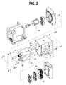
- FIG. 2shows the blower of FIG. 1 in exploded form.
- FIGS. 3 , 4 and 5are perspective views that show pairs of rotors, rotated out of alignment for clarity, in zero-, thirty-degree-, and sixty-degree-angle positions, respectively, and including a line on each rotor representing a locus of flow gap between the rotors for each position.
- FIG. 6shows a section view of the housing component of a blower according to the prior art.
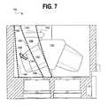
- FIG. 7shows a corresponding section view of the housing component of a blower according to the present invention.
- FIG. 8shows the opposite section of the housing of FIG. 7 according to the present invention.
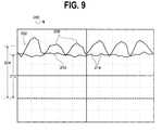
- FIG. 9plots leakback variation over 1 revolution for substantially identical blowers, one of which is made according to prior art, and the other of which is substantially identical to prior art, but also incorporates the features of the instant invention.
- Some embodiments in accordance with the present inventionprovide an improved Roots-type blower wherein production of noise artifacts related to leakback variation with rotor angular position is reduced in comparison to previous Roots-type blowers.
- Rotors described in the discussion that followsare cycloidal rather than involute in section. This omits a tendency to instantaneously trap and compress fluid volumes, and thus eliminates an additional well-understood noise source.
- Helical rotorscan be configured to provide substantially constant output rate over a cycle of rotation, particularly when compared to the pulsating output rate characteristic of straight rotors.
- leakbackmay be rendered more variable in the otherwise-desirable helical rotors than in straight rotors by a particular dimension of helical rotors.
- FIG. 1is a perspective view of an example of a Roots-type blower 10 , wherein a housing 12 is bounded on a first end by a motor cover 14 , and on a second end by a gear cover 16 .
- An inlet 18is established by the housing 12 shape and by an inlet port cover 20 , with the latter concealing the inlet port 22 in this view.
- An outlet 24is likewise established by the housing 12 shape and by an outlet port cover 26 , concealing the outlet port 28 .
- FIG. 2is an exploded perspective view of the blower of FIG. 1 , less the inlet and outlet port covers.
- the housing 12includes a twinned chamber 30 .
- the driving rotor 32(connected to the motor 34 ) and the driven (idler) rotor 36 may be seen to form mirror-image helices, configured to counter-rotate with a constant gap between proximal surfaces along a continuous line, as addressed in detail below.
- Driving and driven (idler) gears 38 and 40are adjustably coupled to the respective rotors 32 and 36 .
- the inlet port 22 and outlet port 28may be seen in this view. Details of fastenings and bearings are not affected by the invention, and are not further addressed herein.
- Section plane A-A-A-Aincludes the rotor axes 46 , 48 , coinciding with the bore axes of the twinned chamber 30 .
- the interface between the helical rotors 32 , 36 and the chamber 30 in which they operatehas substantially flat first (motor)-end 42 and second (gear)-end 44 boundaries of largely constant leakback flow resistance, and, prior to the present invention, perimeter wall boundaries that were likewise largely constant in leakback flow resistance.
- the interface between two properly formed and spaced and substantially mirror-image helical rotors 32 , 36has a boundary over the length of the rotors that varies periodically with angular position. There is a particular angle exhibiting minimum leakback that recurs at six positions (assuming the two three-lobe rotors of the figures) during each rotation.
- FIG. 3is a perspective view 50 showing respective rotors 32 , 36 tilted away from one another, oriented in a first one of these minimum-leakback angular positions, referred to herein as the zero-angle position.
- a first lobe 52 of the first helical rotor 32is fully engaged with a first interlobe trough 54 of the second helical rotor 36 , and first lobe 52 and trough 54 are aligned with plane A-A of the rotor axes 46 , 48 (shown in FIG. 2 ), at the proximal end (closest to the viewer; this may be the gear end, although the shaft is omitted) of the rotors 32 , 36 .
- a second lobe 58part of the second rotor 36 , is fully engaged with a second trough 56 , part of the first rotor 32 , at the distal end (the motor end if the proximal end is the gear end) of the rotors 32 , 36 , also in plane A-A.
- a sinuous gap path 60having substantially uniform thickness exists. The leakback through this sinuous gap path 60 (when the rotors are parallel as shown in FIG. 2 ) is likewise substantially uniform, and, as mentioned, at a minimum.
- the path 60is shown as a heavy bold line on both rotors 32 , 36 , dashed where view is blocked by the interposed lobes.
- the gap 60 between the rotors 32 , 36 at the proximal end, middle, and distal endeffectively follows a continuous line that lies approximately in both the plane A-A of the rotor axes and in an interface plane B-B, likewise indicated in FIG. 2 , which is a plane perpendicular to the rotor axis plane A-A, and equidistant between the rotor axes 46 , 48 .
- NLBnatural leakback
- gap length 66that is, the travel distance for molecules passing from high to low pressure, is a relatively insignificant factor in flow resistance for mechanical devices, and thus between the rotors 32 , 36 .
- Gap cross-sectional areais of greater importance in flow resistance, and thus in leakback in the case of Roots-type blowers.
- FIG. 4shows the rotors 32 , 36 of FIG. 3 , tilted apart for illustrative purposes as before, advanced thirty degrees in rotation.
- the proximal end of the first lobe 52previously centered, has advanced, although a transition point 100 on the first lobe 52 is still fully in proximity to a corresponding point 100 on the second rotor 36 .
- transition points 102are now becoming disengaged, while a second engagement is forming at corresponding transition points 104 , between the second trough 56 and the third lobe 106 and between the second lobe 58 and the third trough 108 .
- the second lobe 58 transition to the third trough 108is at the end of its engagement at corresponding points 110 (overlapping) with the transition between the second trough 56 and the third lobe 106 .
- a gap path 112 between the rotors 32 , 36has a maximum extent—the gap has an extended shift from 102 to 104 , adding about 40% to the width in some embodiments, while the gap thickness remains substantially uniform. Since pressure between the outlet and inlet ports may be constant, this greater width results in lower flow resistance. This lower flow resistance is associated with maximum leakback. It is to be observed that, while the path 112 at the thirty degree rotational position remains roughly in the interface plane B-B, it is distended out of the plane of the rotor axes 68 in greater part than the gap path 60 shown in FIG. 3 . As a consequence, the direction of leakback flow has at least a component 114 that is axial, that is, perpendicular to the outlet-to-inlet port direction, in a proximal-to-distal direction.
- the sixty degree position 116shown in FIG. 5 , mirrors the zero degree position of FIG. 3 , with leakback through a sinuous gap path 118 again at a minimum.
- the ninety degree positionnot shown, mirrors the thirty degree position of FIG. 4 .
- the angle between the sinuous gap path and the rotor axis planeis reversed, so that the axial component of flow is reversed from that of the axial component of flow 114 of the thirty degree position, to a distal-to-proximal direction.
- FIG. 6is a section view 120 , looking toward the outlet port 122 , of a prior-art chamber. Dashed lines represent a lobe tip at representative positions. A first dashed line 124 represents a lobe tip still end-to-end proximal to—and providing a baseline extent of leakback with respect to—the chamber wall 126 . In this position, the lobe tip serves as the leading edge of a gulp that holds an air volume not yet directly in contact with fully pressurized air at the outlet port 122 .
- a second line 128represents the same lobe tip, advanced sufficiently to begin opening a relief groove 130 , let into the chamber with gradually increasing depth of penetration of the chamber wall, and ultimately cutting into the outlet port 122 sidewall (the perimeter surface perpendicular to the rotor axis plane A-A), whereby air pressure present at the outlet port 122 begins to be introduced into the gulp.
- a third line 132represents the same lobe tip, advanced sufficiently to open the gulp directly to the outlet port 122 . When the lobe tip has advanced to the position of a fourth line 134 , the gulp is fully open to the outlet port 122 .
- FIG. 7shows a section view 140 of a chamber incorporating an embodiment of the invention.
- the viewis outward toward the outlet port 142 , with dashed lines representing lobe tips at illustrative positions during regular (i.e., transport from inlet to outlet) rotor motion 146 .
- a first line 144represents a lobe tip still fully proximal to the chamber wall 148
- a second line 150represents the same lobe tip, advanced sufficiently to begin opening a relief groove 152 , whereby the outlet port 142 air pressure begins to be introduced into the gulp.
- a third line 162represents the same lobe tip, having advanced sufficiently to begin opening the gulp to the outlet port 142 itself.
- FIG. 8is a section view 170 of a chamber according to the invention, looking instead toward the inlet port 172 .
- Dashed lines 174 , 176 , and 178represent lobe tip positions during regular motion 180 .
- Relief recesses 182 , 184provide auxiliary leakback paths that depend on rotor angular position for the extent of auxiliary leakback provided.
- Lobe tip position 174provides no auxiliary leakback path. This corresponds to the thirty degree angle position of FIG. 6 , wherein natural leakback between rotors 32 , 36 includes axial flow path 114 and is maximized.
- Lobe tip position 176provides a maximized auxiliary leakback path. This corresponds to the zero rotor angle position of FIG. 3 , wherein natural leakback between rotors 32 , 36 is minimized, and to lobe tip position 150 of FIG. 7 , wherein relief groove 152 provides appreciable coupling into the same otherwise-closed gulp.
- the combination of coupling into the gulp as shown in FIG. 7 and coupling out of the gulp as shown in FIG. 8provides leakback than can be calibrated by adjusting shape, size, and position of relief recesses 182 , 184 to offset variations in natural leakback to an arbitrarily precise extent.
- the phenomenarepeat at six rotation angles, alternating between the rotors, for a blower having two three-lobed helical rotors. Intermediate angles realize intermediate and alternating exposure of relief recesses 182 , 184 , so that leakback may be adjusted to remain substantially constant with angle. Natural leakback flow may be seen to be largely directed from outlet to inlet, and thus non-axial, at minimum flow, for which the relief recesses 182 , 184 provide an auxiliary path, and to have a significant axial component 114 , shown in FIG. 6 , at maximum extents of natural leakback flow.
- Design detail of the relief recesses 182 , 184is optional.
- an arcuate path substantially at right angles to the helical lobe tip lineis defined with maximum width and depth generally aligned with the rotor angle of minimum natural leakback, and with depth and width going to zero—i.e., no penetration of the chamber wall—at angles of maximum natural leakback.
- Axial location of the relief recesses 182 , 184is generally centered in the respective walls of the chamber in the embodiment shown.
- Verification of specific configurationsis necessarily experimental, emphasizing both air pressure range and acoustic measurements, as a plurality of factors, such as edge shapes, surface finishes, cavity resonances, and the like, may contribute noise to a specific configuration despite general conformance to the indicated arrangement.
- a representative prior-art blowersuch as that whereof the outlet side is shown above in FIG. 6 , may employ substantially the same inlet arrangement as that shown in FIG. 8 , except without relief recesses 182 , 184 , and with the profile of the input port 172 inverted, as represented by dashed port 186 .
- This inverted input port 186 profilecan cause a more abrupt closing of the port 186 by the lobe tip transitioning past edge position 178 .
- FIG. 9is a plot 200 of leakback flow as a function of angle for prior and inventive designs, showing that the above-described variation in gap width and thus in flow resistance produces measurable variation in leakback, and consequently a measurable noise artifact directly associated with rotation speed and outlet pressure.
- Variable leakback for a prior designmanifests in a first graph of leakback flow 202 . This is non-constant 204 over angular position, and exhibits a noticeable peak 206 six times per shaft revolution.
- FIG. 9further shows a second graph 210 of output pressure as a function of angular position, realized by incorporating the inventive improvement into an otherwise substantially identical blower.
- the nominal leakback flow 212is comparable to that 204 of the baseline blower, but the magnitude of pressure peaks 214 associated with the minimum leakback angular positions of FIGS. 3 and 5 is appreciably lower.
- the sources of this improvementinclude providing relief recesses 182 , 184 , such as those in the embodiment shown in FIG. 8 , along with secondary improvements introduced through inverting the input port from 186 to 172 and modifying the relief grooves from 130 to 152 , as shown in FIGS. 6 and 7 .
- the rotors, shafts, gears, and associated partsmay be fabricated either from the same alloy or from another material having a substantially equal—and isotropic—C T .
- Poly ether ether ketone (PEEK)to cite one of several engineering plastics that may be suited to rotor applications, may be filled with materials that jointly realize a product with a C T that closely conforms to that of certain aluminum alloys, and may thus be suited to inclusion in a low-noise blower according to the invention.
- a relief recess constructmay be derived that is consistent with a specific embodiment, substantially similar to that shown in FIG. 8 , wherein a blower has three-lobe cycloidal rotors with sixty degree helical advance.
- the rotorsoperate within a chamber having a wall as described above.
- Relief recesses compatible with this blowerlie within cylindrical reference volumes.
- Each reference volumehas an axis of rotation lying in a reference plane defined approximately by the slope (line) of the helix of a rotor lobe tip at a mid-chamber plane perpendicular to the rotor axis, and by the intersection (point) of the mid-chamber plane with the proximal rotor axis.
- the axis of rotation of the reference volumeis parallel to the helix slope at a point of intersection between the reference plane and the chamber wall.
- the reference volume radiusexceeds the rotor lobe radius.
- the reference volumeintersects the chamber wall along a continuous path further limited in extent by the rotor axis plane and a limit plane parallel to the interface plane and including the proximal rotor axis.
- the relief recessmay have radiused surfaces rather than occupying the entire reference volume.
- a lobe in motion over the relief recessmay provide maximum bypass area when centered over the relief recess if the geometry of the relief recess includes at least a principal radius (the radius of the reference volume described above) greater than the radius of the lobe at its addendum extent (maximum rotor radius), as shown in FIG. 3 , for example.
Landscapes
- Engineering & Computer Science (AREA)
- Mechanical Engineering (AREA)
- General Engineering & Computer Science (AREA)
- Applications Or Details Of Rotary Compressors (AREA)
- Structures Of Non-Positive Displacement Pumps (AREA)
- Rotary Pumps (AREA)
Abstract
Description
Claims (12)
Priority Applications (5)
| Application Number | Priority Date | Filing Date | Title |
|---|---|---|---|
| US12/050,541US7997885B2 (en) | 2007-12-03 | 2008-03-18 | Roots-type blower reduced acoustic signature method and apparatus |
| CA2644879ACA2644879C (en) | 2007-12-03 | 2008-11-26 | Roots-type blower reduced acoustic signature method and apparatus |
| EP08170504AEP2067998A3 (en) | 2007-12-03 | 2008-12-02 | Roots-type blower reduced acoustic signature method and apparatus |
| CN200810184002.5ACN101451528B (en) | 2007-12-03 | 2008-12-03 | Roots-type blower reduced acoustic signature method and apparatus |
| JP2008308082AJP5577031B2 (en) | 2007-12-03 | 2008-12-03 | Method and apparatus for reducing the acoustic characteristics of a Roots blower |
Applications Claiming Priority (2)
| Application Number | Priority Date | Filing Date | Title |
|---|---|---|---|
| US99197707P | 2007-12-03 | 2007-12-03 | |
| US12/050,541US7997885B2 (en) | 2007-12-03 | 2008-03-18 | Roots-type blower reduced acoustic signature method and apparatus |
Publications (2)
| Publication Number | Publication Date |
|---|---|
| US20090142213A1 US20090142213A1 (en) | 2009-06-04 |
| US7997885B2true US7997885B2 (en) | 2011-08-16 |
Family
ID=40456695
Family Applications (1)
| Application Number | Title | Priority Date | Filing Date |
|---|---|---|---|
| US12/050,541Expired - Fee RelatedUS7997885B2 (en) | 2007-12-03 | 2008-03-18 | Roots-type blower reduced acoustic signature method and apparatus |
Country Status (5)
| Country | Link |
|---|---|
| US (1) | US7997885B2 (en) |
| EP (1) | EP2067998A3 (en) |
| JP (1) | JP5577031B2 (en) |
| CN (1) | CN101451528B (en) |
| CA (1) | CA2644879C (en) |
Cited By (9)
| Publication number | Priority date | Publication date | Assignee | Title |
|---|---|---|---|---|
| US20100111736A1 (en)* | 2008-11-03 | 2010-05-06 | Pulmonetic Systems, Inc. | Roots-type blower rotor alignment method and apparatus |
| US20100147301A1 (en)* | 2005-03-01 | 2010-06-17 | Resmed Limited | Recognition System for an Apparatus That Delivers Breathable Gas to a Patient |
| US20110139154A1 (en)* | 2005-12-21 | 2011-06-16 | Resmed Limited | Identification system and method for mask and ventilator components |
| US20120020824A1 (en)* | 2010-07-20 | 2012-01-26 | Paul Xiubao Huang | Roots supercharger with a shunt pulsation trap |
| DE202012010401U1 (en)* | 2012-10-31 | 2014-02-03 | Hugo Vogelsang Maschinenbau Gmbh | Rotary pump with direct drive |
| USD745056S1 (en)* | 2012-06-04 | 2015-12-08 | Eaton Corporation | Blower housing |
| EP3298281A1 (en)* | 2015-05-20 | 2018-03-28 | Casappa S.p.A. | Gear pump and method for realising it |
| US11131307B2 (en) | 2015-08-17 | 2021-09-28 | Eaton Intelligent Power Limited | Hybrid profile supercharger rotors |
| US20240426299A1 (en)* | 2020-04-03 | 2024-12-26 | Industrial Technologies And Services, Llc | Low coefficient of expansion rotors for blowers |
Families Citing this family (4)
| Publication number | Priority date | Publication date | Assignee | Title |
|---|---|---|---|---|
| US9683521B2 (en)* | 2013-10-31 | 2017-06-20 | Eaton Corporation | Thermal abatement systems |
| CN112815070B (en)* | 2021-01-25 | 2025-02-11 | 宿迁学院 | A fixed-point conjugated three-twisted blade volumetric rotor pair and a power helical gear pair |
| CN113007095B (en)* | 2021-01-25 | 2025-02-25 | 宿迁学院 | A convex-flat conjugate three-twisted blade rotor volume pair and helical gear power pair |
| CN116464632B (en)* | 2023-05-10 | 2025-06-24 | 德帕姆(杭州)泵业科技有限公司 | Three-blade spiral rotor with impact resistance |
Citations (209)
| Publication number | Priority date | Publication date | Assignee | Title |
|---|---|---|---|---|
| US56614A (en) | 1866-07-24 | Improvement in cross-heads for blowers | ||
| US587907A (en) | 1897-08-10 | Piston for rotary pumps | ||
| US1769153A (en) | 1928-03-07 | 1930-07-01 | Meyer William Warren | Rotary blower or pump |
| US2014932A (en) | 1933-03-17 | 1935-09-17 | Gen Motors Corp | Roots blower |
| US2787999A (en) | 1951-09-13 | 1957-04-09 | Bennett Vivian Ray | Respiratory ventilation meter |
| US3089638A (en) | 1958-12-01 | 1963-05-14 | Dresser Ind | Impellers for fluid handling apparatus of the rotary positive displacement type |
| US3094274A (en) | 1960-04-29 | 1963-06-18 | Harris A Thompson | Artificial respirator apparatus |
| US3286643A (en)* | 1963-10-14 | 1966-11-22 | Dowty Technical Dev Ltd | Gear pumps and motors |
| US3371856A (en) | 1966-03-24 | 1968-03-05 | Fuller Co | Modified cycloidal impeller |
| US3459395A (en) | 1967-08-16 | 1969-08-05 | Ambac Ind | Shock isolating means |
| US3658443A (en) | 1969-11-21 | 1972-04-25 | Giovanni Fumagalli | Pressure alternating device for automatic lungs ventilator actuation |
| US3941206A (en) | 1974-05-08 | 1976-03-02 | Burgess Industries Incorporated | Noise attenuating snubber |
| US4080103A (en) | 1977-01-12 | 1978-03-21 | Bird F M | Portable air compressor system for respirator |
| US4121578A (en) | 1976-10-04 | 1978-10-24 | The Bendix Corporation | Physiological responsive control for an oxygen regulator |
| US4215977A (en) | 1977-11-14 | 1980-08-05 | Calspan Corporation | Pulse-free blower |
| US4220219A (en) | 1978-09-14 | 1980-09-02 | Flugger Ray T | Lightweight muffler and method for muffling noise |
| US4227869A (en) | 1976-10-19 | 1980-10-14 | Atlas Copco Aktiebolag | Intermeshing pump rotor gears with involute and linear flank portions |
| US4239039A (en) | 1979-02-28 | 1980-12-16 | Thompson Harris A | Dual control valve for positive pressure artificial respiration apparatus |
| US4267899A (en) | 1979-08-31 | 1981-05-19 | Donaldson Company, Inc. | Muffler assembly |
| US4323064A (en) | 1976-10-26 | 1982-04-06 | Puritan-Bennett Corporation | Volume ventilator |
| US4448192A (en) | 1982-03-05 | 1984-05-15 | Hewlett Packard Company | Medical ventilator device parametrically controlled for patient ventilation |
| US4455132A (en) | 1982-02-23 | 1984-06-19 | Fiat Auto S.P.A. | Volumetric compressor of the roots type |
| US4495947A (en) | 1982-09-23 | 1985-01-29 | Imasco-Cdc Research Foundation | High speed medical ventilator |
| US4556373A (en)* | 1984-09-04 | 1985-12-03 | Eaton Corporation | Supercharger carryback pulsation damping means |
| US4564345A (en) | 1984-09-04 | 1986-01-14 | Eaton Corporation | Supercharger with reduced noise |
| JPS61123793A (en)* | 1984-11-16 | 1986-06-11 | Osaka Shinku Kiki Seisakusho:Kk | Roots vacuum pump |
| US4595349A (en) | 1983-06-20 | 1986-06-17 | Eaton Corp. | Supercharger rotor, shaft, and gear arrangement |
| DE3238015C2 (en) | 1982-10-13 | 1986-07-31 | Aerzener Maschinenfabrik Gmbh, 3251 Aerzen | Roots compressor |
| US4609335A (en) | 1984-09-20 | 1986-09-02 | Eaton Corporation | Supercharger with reduced noise and improved efficiency |
| US4666384A (en) | 1983-09-30 | 1987-05-19 | Aisin Seiki Kabushiki Kaisha | Roots type blower with reduced gaps between the rotors |
| US4673058A (en) | 1986-05-09 | 1987-06-16 | G Enterprises Limited | High performance automotive muffler |
| US4684330A (en) | 1980-08-28 | 1987-08-04 | Stal Refrigeration Ab | Drive for rotary compressor |
| US4686999A (en) | 1985-04-10 | 1987-08-18 | Tri Fund Research Corporation | Multi-channel ventilation monitor and method |
| US4702240A (en) | 1986-07-22 | 1987-10-27 | Bear Medical Systems, Inc. | Demand-responsive gas blending system for medical ventilator |
| DE3620792A1 (en) | 1986-06-20 | 1987-12-23 | Wankel Gmbh | EXTERNAL ROTATION PISTON BLOWER |
| GB2157370B (en) | 1984-04-13 | 1988-08-17 | Aerzener Maschf Gmbh | Roots compressor for compressing of gaseous media |
| US4768934A (en) | 1985-11-18 | 1988-09-06 | Eaton Corporation | Port arrangement for rotary positive displacement blower |
| US4794922A (en) | 1986-11-04 | 1989-01-03 | Bird Products Corporation | Ventilator manifold |
| DE3414064C2 (en) | 1982-10-13 | 1989-03-23 | Aerzener Maschinenfabrik Gmbh, 3258 Aerzen, De | |
| US4844044A (en) | 1988-06-27 | 1989-07-04 | Eaton Corporation | Torsion damping mechanism for a supercharger |
| US4846302A (en) | 1986-08-08 | 1989-07-11 | Tenneco Inc. | Acoustic muffler |
| US4867151A (en) | 1987-10-19 | 1989-09-19 | Bird F M | Mobile self-contained ventilator |
| US4938670A (en) | 1989-10-02 | 1990-07-03 | Tocew Lee | Rotary fluid machine |
| US4957107A (en) | 1988-05-10 | 1990-09-18 | Sipin Anatole J | Gas delivery means |
| US4975032A (en) | 1987-07-07 | 1990-12-04 | Fuji Jukogyo Kabushiki Kaisha | Roots type blower having reduced gap between rotors for increasing efficiency |
| US5040959A (en) | 1989-02-17 | 1991-08-20 | Fuji Jukogyo Kabushiki Kaisha | Roots blower with improved clearance between rotors |
| US5056995A (en) | 1989-02-28 | 1991-10-15 | Aisin Seiki Kabushiki Kaisha | Displacement compressor with reduced compressor noise |
| US5131829A (en) | 1991-06-19 | 1992-07-21 | Eaton Corporation | Trapped volume vent means for meshing lobes of roots-type supercharger |
| US5145349A (en) | 1991-04-12 | 1992-09-08 | Dana Corporation | Gear pump with pressure balancing structure |
| US5152684A (en) | 1990-08-27 | 1992-10-06 | Leybold Aktiengesellschaft | Rotor profile for a roots vacuum pump |
| US5161525A (en) | 1990-05-11 | 1992-11-10 | Puritan-Bennett Corporation | System and method for flow triggering of pressure supported ventilation |
| EP0239026B1 (en) | 1986-03-24 | 1993-05-12 | Performance Controls, Inc. | Method and apparatus for determining shaft position and for providing commutation signals |
| US5211170A (en) | 1991-04-01 | 1993-05-18 | Press Roman J | Portable emergency respirator |
| US5222148A (en) | 1992-04-29 | 1993-06-22 | General Motors Corporation | Active noise control system for attenuating engine generated noise |
| US5237987A (en) | 1990-06-07 | 1993-08-24 | Infrasonics, Inc. | Human lung ventilator system |
| US5239994A (en) | 1991-05-10 | 1993-08-31 | Bunnell Incorporated | Jet ventilator system |
| US5335651A (en) | 1990-05-16 | 1994-08-09 | Hill-Rom Company, Inc. | Ventilator and care cart each capable of nesting within and docking with a hospital bed base |
| US5350888A (en) | 1992-05-01 | 1994-09-27 | Tennessee Gas Pipeline Company | Broad band low frequency passive muffler |
| US5398676A (en) | 1993-09-30 | 1995-03-21 | Press; Roman J. | Portable emergency respirator |
| US5439358A (en) | 1994-01-27 | 1995-08-08 | Weinbrecht; John F. | Recirculating rotary gas compressor |
| EP0521709B1 (en) | 1991-07-01 | 1996-05-08 | Kabushiki Kaisha Toshiba | Power converting device with inverter circuitry for driving multiple-phase variable-speed motor |
| US5542416A (en) | 1994-01-12 | 1996-08-06 | Societe D'applications Industrielles Medicales Et Electroniques (Saime) | Apparatus for assisting ventilation including reduced exhalation pressure mode |
| US5577152A (en) | 1995-04-12 | 1996-11-19 | Chen; Ruey-Zon | Motor assembly |
| US5582163A (en) | 1993-12-06 | 1996-12-10 | Intermed Equipamento Medico Hospitalar Ltda. | Respiratory control system and apparatus |
| US5632270A (en) | 1994-09-12 | 1997-05-27 | Puritan-Bennett Corporation | Method and apparatus for control of lung ventilator exhalation circuit |
| US5638600A (en) | 1994-10-07 | 1997-06-17 | Ford Motor Company | Method of making an efficiency enhanced fluid pump or compressor |
| US5664563A (en) | 1994-12-09 | 1997-09-09 | Cardiopulmonary Corporation | Pneumatic system |
| US5687717A (en) | 1996-08-06 | 1997-11-18 | Tremont Medical, Inc. | Patient monitoring system with chassis mounted or remotely operable modules and portable computer |
| US5694926A (en) | 1994-10-14 | 1997-12-09 | Bird Products Corporation | Portable drag compressor powered mechanical ventilator |
| US5702240A (en) | 1995-05-05 | 1997-12-30 | Tuthill Corporation | Rotary positive displacement blower having a diverging outlet part |
| US5701883A (en) | 1996-09-03 | 1997-12-30 | Respironics, Inc. | Oxygen mixing in a blower-based ventilator |
| US5760348A (en) | 1994-04-28 | 1998-06-02 | Heuser; Stephen Glen | Noise attenuating apparatus |
| US5763792A (en) | 1996-05-03 | 1998-06-09 | Dragerwerk Ag | Respiratory flow sensor |
| US5783782A (en) | 1996-10-29 | 1998-07-21 | Tenneco Automotive Inc. | Multi-chamber muffler with selective sound absorbent material placement |
| US5823186A (en) | 1996-06-20 | 1998-10-20 | Dragerwerk Ag | Respirator |
| US5831223A (en) | 1997-09-24 | 1998-11-03 | Kesselring; Stephen H. | Self-tuning exhaust muffler |
| US5918597A (en) | 1998-01-15 | 1999-07-06 | Nellcor Puritan Bennett | Peep control in a piston ventilator |
| US5931159A (en) | 1995-09-09 | 1999-08-03 | Origin Medical Instrument Co., Ltd. | Lung ventilator |
| US5944501A (en) | 1996-06-28 | 1999-08-31 | Anlet Co., Ltd. | Roots blower having zigzag meandering grooves in the casing inner wall surface |
| EP0938909A1 (en) | 1997-12-15 | 1999-09-01 | Siemens-Elema AB | Ventilator system |
| DE19817356A1 (en) | 1998-04-18 | 1999-10-21 | Bosch Gmbh Robert | Angle indicator for determining an angle between a sensor arrangement and a magnetic field |
| US6009871A (en) | 1996-11-14 | 2000-01-04 | Dragerwek Aktiengesellschaft | Ventilating apparatus |
| US6076523A (en) | 1998-01-15 | 2000-06-20 | Nellcor Puritan Bennett | Oxygen blending in a piston ventilator |
| US6099277A (en) | 1998-08-12 | 2000-08-08 | Dresser Industries, Inc. | Gas blower and method utilizing recirculation openings |
| US6102038A (en) | 1998-05-15 | 2000-08-15 | Pulmonetic Systems, Inc. | Exhalation valve for mechanical ventilator |
| US6125844A (en) | 1998-04-30 | 2000-10-03 | Westwood Biomedical | Portable oxygen based drug delivery system |
| US6152129A (en) | 1996-08-14 | 2000-11-28 | Resmed Limited | Determination of leak and respiratory airflow |
| US6152135A (en) | 1998-10-23 | 2000-11-28 | Pulmonetic Systems, Inc. | Ventilator system |
| US6155257A (en) | 1998-10-07 | 2000-12-05 | Cprx Llc | Cardiopulmonary resuscitation ventilator and methods |
| US6158434A (en) | 1996-02-27 | 2000-12-12 | Henk W. Koster | Ventilatory system with additional gas administrator |
| US6164412A (en) | 1998-04-03 | 2000-12-26 | Arvin Industries, Inc. | Muffler |
| US6176693B1 (en) | 1997-03-17 | 2001-01-23 | Finder Pompe S.P.A. | Volumetric blower with covers having a duct for connection to the delivery manifold |
| JP2001050774A (en) | 1999-08-06 | 2001-02-23 | Tamagawa Seiki Co Ltd | Sine cosine output sensor and servo motor using the same |
| US6279574B1 (en) | 1998-12-04 | 2001-08-28 | Bunnell, Incorporated | Variable flow and pressure ventilation system |
| US6283246B1 (en) | 1998-07-16 | 2001-09-04 | Betech Co., Ltd. | Silencer |
| US6305372B1 (en) | 1995-04-07 | 2001-10-23 | John L. Servidio | Pressure support ventilatory assist system |
| US20010044588A1 (en) | 1996-02-22 | 2001-11-22 | Mault James R. | Monitoring system |
| US6354558B1 (en) | 1998-11-20 | 2002-03-12 | Carrier Corporation | Compressor mounting |
| EP1243282A1 (en) | 2001-03-21 | 2002-09-25 | Airox | Ventilator |
| US20020134378A1 (en) | 2001-03-26 | 2002-09-26 | Finnegan Linda A. | Sound dampening housing for respiratory assist devices |
| US6474960B1 (en) | 2000-03-21 | 2002-11-05 | DRäGER MEDIZINTECHNIK GMBH | Respirator radial compressor with reduced sound emission |
| US6484719B1 (en) | 1996-09-23 | 2002-11-26 | Resmed, Inc. | Method for providing ventilatory assistance in a spontaneously breathing subject |
| US20030057904A1 (en) | 2001-08-22 | 2003-03-27 | Sacher Ing. Manfred | Process and device for feedback-controlling rotary machines |
| US6543449B1 (en) | 1997-09-19 | 2003-04-08 | Respironics, Inc. | Medical ventilator |
| JP2003124986A (en) | 2001-10-18 | 2003-04-25 | Fujitsu Ltd | VPN service management system, VPN service manager and VPN service agent |
| US6558137B2 (en) | 2000-12-01 | 2003-05-06 | Tecumseh Products Company | Reciprocating piston compressor having improved noise attenuation |
| US6564798B1 (en) | 1999-07-15 | 2003-05-20 | Siemens Elema Ab | Method and computer software product for controlling an expiratory valve in a ventilator |
| US6571796B2 (en) | 2001-02-08 | 2003-06-03 | University Of Florida | Tracheal pressure ventilation respiratory system |
| US6571792B1 (en) | 1997-10-15 | 2003-06-03 | Datex-Ohmeda, Inc. | Smart modular anesthesia respiratory system |
| US6591835B1 (en) | 1997-09-26 | 2003-07-15 | Airon Corporation | Pneumatically controlled multifunction medical ventilator |
| US6615831B1 (en) | 1999-07-02 | 2003-09-09 | Respironics, Inc. | Pressure support system and method and a pressure control valve for use in such system and method |
| US6619286B2 (en) | 2000-06-16 | 2003-09-16 | 3M Innovative Properties Company | Pressure regulator for a respirator system |
| US6626175B2 (en) | 2000-10-06 | 2003-09-30 | Respironics, Inc. | Medical ventilator triggering and cycling method and mechanism |
| US6629934B2 (en) | 2000-02-02 | 2003-10-07 | Healthetech, Inc. | Indirect calorimeter for medical applications |
| US6629525B2 (en) | 2000-08-03 | 2003-10-07 | Sequal Technologies, Inc. | Portable oxygen concentration system and method of using the same |
| US6629531B2 (en) | 2000-04-17 | 2003-10-07 | Scott Technologies, Inc. | Respiratory mask and service module |
| US6631716B1 (en) | 1998-07-17 | 2003-10-14 | The Board Of Trustees Of The Leland Stanford Junior University | Dynamic respiratory control |
| US6637430B1 (en) | 2000-06-16 | 2003-10-28 | Ponwell Enterprises Limited | Respiratory delivery system with power/medicament recharge assembly |
| US20030208113A1 (en) | 2001-07-18 | 2003-11-06 | Mault James R | Closed loop glycemic index system |
| US6666209B2 (en) | 2001-02-20 | 2003-12-23 | 3M Innovative Properties Company | Method and system of calibrating air flow in a respirator system |
| US6672300B1 (en) | 1999-06-23 | 2004-01-06 | Graham Cameron Grant | Respiration assistor |
| US6691707B1 (en) | 1999-06-18 | 2004-02-17 | Resmed Limited | Connector for a respiratory mask and a respiratory mask |
| US6691702B2 (en) | 2000-08-03 | 2004-02-17 | Sequal Technologies, Inc. | Portable oxygen concentration system and method of using the same |
| US6708690B1 (en) | 1999-09-03 | 2004-03-23 | Respironics, Inc. | Apparatus and method for providing high frequency variable pressure to a patient |
| US20040074495A1 (en) | 2000-12-29 | 2004-04-22 | Wickham Peter John Deacon | Characterisation of mask systems |
| US6745770B2 (en) | 2002-01-08 | 2004-06-08 | Resmed Limited | Flow diverter for controlling the pressure and flow rate in a CPAP device |
| US6752240B1 (en) | 2002-11-05 | 2004-06-22 | Brunswick Corporation | Sound attenuator for a supercharged marine propulsion device |
| US6764534B2 (en) | 2002-01-31 | 2004-07-20 | Airsep Corporation | Portable oxygen concentrator |
| US20040147818A1 (en) | 2002-11-18 | 2004-07-29 | Andrew Levy | Portable system for monitoring and processing patient parameters in multiple oprational modes |
| US6770037B2 (en) | 1987-06-26 | 2004-08-03 | Resmed Limited | Method and apparatus useful in the diagnosis of obstructive sleep apnea of a patient |
| US6782888B1 (en) | 1999-04-07 | 2004-08-31 | Event Medical Ltd. | Breathing apparatus |
| EP1130761A3 (en) | 2000-02-29 | 2004-09-29 | Hitachi, Ltd. | A motor driving circuit, a method for driving a motor, and a semiconductor integrated circuit device |
| US6802225B2 (en) | 2002-07-24 | 2004-10-12 | Versamed Medical Systems Ltd. | Differential pressure sensor with sloped strut edges for respiratory monitoring |
| US20040211422A1 (en) | 2003-04-28 | 2004-10-28 | Ric Investments, Inc. | Pressure/flow control valve and system using same |
| US20040221854A1 (en) | 1998-12-22 | 2004-11-11 | Respironics Inc. | Insufflation system and method |
| US20040226562A1 (en) | 2002-12-06 | 2004-11-18 | Bordewick Steven S. | Blower assembly for CPAP |
| US6820618B2 (en) | 1999-02-03 | 2004-11-23 | University Of Florida Research Foundation, Incorporated | Method and apparatus for nullifying the imposed work of breathing |
| US6837260B1 (en) | 1999-11-02 | 2005-01-04 | Respironics, Inc. | Pressure support system having a two-piece assembly |
| US20050112013A1 (en) | 2003-08-04 | 2005-05-26 | Pulmonetic Systems, Inc. | Method and apparatus for reducing noise in a roots-type blower |
| US20050124866A1 (en) | 2003-11-12 | 2005-06-09 | Joseph Elaz | Healthcare processing device and display system |
| US20050166921A1 (en) | 2003-08-04 | 2005-08-04 | Pulmonetic Systems, Inc. | Method and apparatus for attenuating compressor noise |
| US20050188991A1 (en) | 2003-06-04 | 2005-09-01 | Jianuo Sun | Positive airway pressure therapy management module |
| US20050241642A1 (en) | 2003-11-12 | 2005-11-03 | Krzysztofik J M | Breathing respirator |
| US6968842B1 (en) | 2002-04-03 | 2005-11-29 | Ric Investments, Inc. | Measurement of a fluid parameter in a pressure support system |
| US7011092B2 (en) | 2002-12-12 | 2006-03-14 | Airsep Corporation | Portable hypoxic apparatus |
| US20060069326A1 (en) | 2004-09-24 | 2006-03-30 | Roger Lee Heath | Resuscitation and life support system, method and apparatus |
| US20060065672A1 (en) | 2004-09-29 | 2006-03-30 | Air Liquide Sante (International) | Medical gas bottle with peripheral protective shell |
| US20060070624A1 (en) | 2004-10-01 | 2006-04-06 | Ric Investments, Llc | Method and apparatus for treating cheyne-stokes respiration |
| US7032589B2 (en) | 2002-01-23 | 2006-04-25 | The Johns Hopkins University | Portable ventilator |
| US20060124128A1 (en) | 2004-11-12 | 2006-06-15 | Deane Geoffrey F | Portable intelligent controller for therapeutic gas systems |
| US7063084B2 (en) | 2004-01-14 | 2006-06-20 | Soutmedic Incorporated | Oxygen diffuser support |
| US7066985B2 (en) | 2003-10-07 | 2006-06-27 | Inogen, Inc. | Portable gas fractionalization system |
| US20060144396A1 (en) | 2003-08-04 | 2006-07-06 | Devries Douglas F | Portable ventilator system |
| US20060144399A1 (en) | 2004-12-17 | 2006-07-06 | Davidowski Doug L | Condensation reduction and management systems in a gas flow delivery system |
| US7073499B1 (en) | 2001-02-06 | 2006-07-11 | Injet Digital Aerosols Limited | Inhaler with airflow regulation |
| US20060150973A1 (en) | 2003-07-04 | 2006-07-13 | Societe D'applications Industrielles | Breathing assistance device |
| US7086366B1 (en) | 1999-04-20 | 2006-08-08 | Metaldyne Machining And Assembly Company, Inc. | Energy efficient fluid pump |
| US20060174872A1 (en) | 2005-02-09 | 2006-08-10 | Vbox, Incorporated | Method and apparatus for controlling the purity of oxygen produced by an oxygen concentrator |
| US20060174878A1 (en) | 2005-02-09 | 2006-08-10 | Vbox, Incorporated | Low power ambulatory oxygen concentrator |
| US20060174877A1 (en) | 2005-02-09 | 2006-08-10 | Vbox, Incorporated | Portable oxygen concentrator with a docking station |
| US20060174871A1 (en) | 2005-02-09 | 2006-08-10 | Vbox, Incorporated | Ambulatory oxygen concentrator with high efficiency adsorbent |
| US20060174882A1 (en) | 2005-02-09 | 2006-08-10 | Vbox, Incorporated | Method of controlling the rate of oxygen produced by an oxygen concentrator |
| US20060174874A1 (en) | 2005-02-09 | 2006-08-10 | Vbox, Incorporated | Adsorbent cartridge for oxygen concentrator |
| US20060174880A1 (en) | 2005-02-09 | 2006-08-10 | Vbox, Incorporated | Ambulatory oxygen concentrator containing a three phase vacuum separation system |
| US20060174881A1 (en) | 2005-02-09 | 2006-08-10 | Vbox, Incorporated | Method of providing ambulatory oxygen |
| US20060174875A1 (en) | 2005-02-09 | 2006-08-10 | Vbox, Incorporated | Ambulatory oxygen concentrator containing a power pack |
| US20060201503A1 (en) | 2002-10-11 | 2006-09-14 | The Regents Of The University Of California | Bymixer apparatus and method for fast-response, adjustable measurement of mixed gas fractions in ventilation circuits |
| US20060213518A1 (en) | 2003-08-04 | 2006-09-28 | Devries Douglas F | Portable ventilator system |
| US7118536B2 (en) | 2003-07-25 | 2006-10-10 | Ric Investments, Llc. | Apnea/hypopnea detection system and method |
| US7121276B2 (en) | 2005-02-09 | 2006-10-17 | Vbox, Incorporated | Personal oxygen concentrator |
| US20060249149A1 (en) | 2003-03-17 | 2006-11-09 | Meier Joerg | Method and arrangement for the tiration of physiological measuring signals in conjunction with the observation of a patient in terms of sleep-related respiratory problems |
| US20060266355A1 (en) | 2005-05-24 | 2006-11-30 | Boaz Misholi | Apparatus and method for controlling fraction of inspired oxygen |
| US20060283450A1 (en) | 2005-06-21 | 2006-12-21 | Ric Investments, Llc. | Respiratory device measurement system |
| US7168429B2 (en) | 2001-10-12 | 2007-01-30 | Ric Investments, Llc | Auto-titration pressure support system and method of using same |
| US7171963B2 (en) | 2005-02-09 | 2007-02-06 | Vbox, Incorporated | Product pump for an oxygen concentrator |
| US7183681B2 (en) | 2002-10-31 | 2007-02-27 | Nsk Ltd. | Electric power steering apparatus |
| US20070044799A1 (en) | 2005-07-08 | 2007-03-01 | Hete Bernie F | Modular oxygen regulator system and respiratory treatment system |
| US20070062532A1 (en) | 2005-09-21 | 2007-03-22 | Choncholas Gary J | Apparatus and method for identifying optimal PEEP |
| US20070062529A1 (en) | 2005-09-21 | 2007-03-22 | Choncholas Gary J | Apparatus and method for determining and displaying functional residual capacity data and related parameters of ventilated patients |
| US20070068526A1 (en) | 2003-11-05 | 2007-03-29 | Bernd Lang | Device for supplying a respiratory gas and air-conduction structure provided in said device |
| US20070079826A1 (en) | 2002-09-17 | 2007-04-12 | Fisher & Paykel Healthcare Limited | Apparatus for delivering humidified gases |
| US20070113843A1 (en) | 2005-11-23 | 2007-05-24 | Hughes Arthur R | Acoustic respiratory therapy apparatus |
| US20070113849A1 (en) | 2005-11-21 | 2007-05-24 | Ric Investments, Llc. | System and method of monitoring respiratory events |
| US7225809B1 (en) | 1999-11-01 | 2007-06-05 | Ric Investments, Llc | Method and apparatus for monitoring and controlling a medical device |
| US7226280B1 (en) | 2006-06-01 | 2007-06-05 | Anlet Co., Ltd. | Roots vacuum pump |
| US20070169776A1 (en) | 2005-09-23 | 2007-07-26 | Jeffrey Kepler | Modular pressure support system |
| US20070181127A1 (en) | 2006-01-20 | 2007-08-09 | Shenzhen Mindray Bio-Medical Electronics Co., Ltd | Method for judging the reverse connection of a flow sensor and a respiratory mechanics measuring module used therein |
| US20070193580A1 (en) | 2005-08-01 | 2007-08-23 | Feldhahn Karl A | Ventilation device |
| US20070215146A1 (en) | 2003-12-29 | 2007-09-20 | Robert Douglas | Mechanical ventilation in the presence of sleep disordered breathing |
| US20070221224A1 (en) | 2006-03-20 | 2007-09-27 | Ric Investments, Llc | Ventilatory control system |
| US20070235030A1 (en) | 2003-08-22 | 2007-10-11 | Teetzel James W | Self-contained breathing system |
| US20070265877A1 (en) | 2006-05-12 | 2007-11-15 | Rice Caeli B D | Informative accessories |
| US20070277825A1 (en) | 2006-04-10 | 2007-12-06 | Bordewick Steven S | Apparatus and methods for providing humidity in respiratory therapy |
| US20080000474A1 (en) | 2004-10-26 | 2008-01-03 | Map Medizin-Technologie Gmbh | Apparatus for Administering a Breathable Gas, and Components Thereof |
| US20080029096A1 (en) | 2006-08-02 | 2008-02-07 | Kollmeyer Phillip J | Pressure targeted ventilator using an oscillating pump |
| US7329304B2 (en) | 2005-04-05 | 2008-02-12 | Respironics Oxytec, Inc. | Portable oxygen concentrator |
| US20080039701A1 (en) | 1999-01-25 | 2008-02-14 | Masimo Corporation | Dual-mode pulse oximeter |
| US20080035149A1 (en) | 2004-03-19 | 2008-02-14 | Scott Health & Safety Ltd. | Respirators |
| US7331342B2 (en) | 2003-10-06 | 2008-02-19 | Michael Spearman | Oxygen humidifier |
| US7335243B2 (en) | 2002-04-22 | 2008-02-26 | Jane Homan | Modular biosafety containment apparatus and system |
| US20080066739A1 (en) | 2006-09-20 | 2008-03-20 | Lemahieu Edward | Methods and systems of delivering medication via inhalation |
| US7351034B2 (en) | 2002-07-23 | 2008-04-01 | Schlumberger Technology Corporation | Impeller device for data acquisition in a flow |
| US20080078395A1 (en) | 2006-09-28 | 2008-04-03 | Peter Chi Fai Ho | Pressure Reducing Vavle |
| US20080099017A1 (en) | 2006-06-16 | 2008-05-01 | Bordewick Steven S | Modular positive airway pressure therapy apparatus and methods |
| US7368005B2 (en) | 2005-04-05 | 2008-05-06 | Respironics Oxytec, Inc. | Portable oxygen concentrator |
| US20080110455A1 (en) | 2006-11-13 | 2008-05-15 | Dunsmore Thomas J | Passive respiratory therapy device |
| US20080110462A1 (en) | 2006-11-10 | 2008-05-15 | Chekal Michael P | Oxygen delivery system |
| US20080110458A1 (en) | 2006-10-02 | 2008-05-15 | Philip Morris Usa Inc. | Continuous high pressure delivery system |
| US20080127976A1 (en) | 2006-11-30 | 2008-06-05 | Acker Jaron M | Apparatus and system for reducing mechanical ventilator noise |
Family Cites Families (4)
| Publication number | Priority date | Publication date | Assignee | Title |
|---|---|---|---|---|
| DE609707C (en)* | 1934-02-17 | 1935-02-21 | Daimler Benz Akt Ges | Gap seal on Roots blowers |
| JP4321206B2 (en)* | 2003-10-17 | 2009-08-26 | 株式会社デンソー | Gas compression device |
| ATE471176T1 (en)* | 2004-08-04 | 2010-07-15 | Pulmonetic Systems Inc | METHOD AND APPARATUS FOR REDUCING NOISE IN A ROOTS TYPE FAN |
| JP2006214448A (en)* | 2006-05-16 | 2006-08-17 | Ebara Corp | Vacuum pump |
- 2008
- 2008-03-18USUS12/050,541patent/US7997885B2/ennot_activeExpired - Fee Related
- 2008-11-26CACA2644879Apatent/CA2644879C/ennot_activeExpired - Fee Related
- 2008-12-02EPEP08170504Apatent/EP2067998A3/ennot_activeWithdrawn
- 2008-12-03JPJP2008308082Apatent/JP5577031B2/ennot_activeExpired - Fee Related
- 2008-12-03CNCN200810184002.5Apatent/CN101451528B/ennot_activeExpired - Fee Related
Patent Citations (223)
| Publication number | Priority date | Publication date | Assignee | Title |
|---|---|---|---|---|
| US56614A (en) | 1866-07-24 | Improvement in cross-heads for blowers | ||
| US587907A (en) | 1897-08-10 | Piston for rotary pumps | ||
| US1769153A (en) | 1928-03-07 | 1930-07-01 | Meyer William Warren | Rotary blower or pump |
| US2014932A (en) | 1933-03-17 | 1935-09-17 | Gen Motors Corp | Roots blower |
| US2787999A (en) | 1951-09-13 | 1957-04-09 | Bennett Vivian Ray | Respiratory ventilation meter |
| US3089638A (en) | 1958-12-01 | 1963-05-14 | Dresser Ind | Impellers for fluid handling apparatus of the rotary positive displacement type |
| US3094274A (en) | 1960-04-29 | 1963-06-18 | Harris A Thompson | Artificial respirator apparatus |
| US3286643A (en)* | 1963-10-14 | 1966-11-22 | Dowty Technical Dev Ltd | Gear pumps and motors |
| US3371856A (en) | 1966-03-24 | 1968-03-05 | Fuller Co | Modified cycloidal impeller |
| US3459395A (en) | 1967-08-16 | 1969-08-05 | Ambac Ind | Shock isolating means |
| US3658443A (en) | 1969-11-21 | 1972-04-25 | Giovanni Fumagalli | Pressure alternating device for automatic lungs ventilator actuation |
| US3941206A (en) | 1974-05-08 | 1976-03-02 | Burgess Industries Incorporated | Noise attenuating snubber |
| US4121578A (en) | 1976-10-04 | 1978-10-24 | The Bendix Corporation | Physiological responsive control for an oxygen regulator |
| US4227869A (en) | 1976-10-19 | 1980-10-14 | Atlas Copco Aktiebolag | Intermeshing pump rotor gears with involute and linear flank portions |
| US4323064A (en) | 1976-10-26 | 1982-04-06 | Puritan-Bennett Corporation | Volume ventilator |
| US4080103A (en) | 1977-01-12 | 1978-03-21 | Bird F M | Portable air compressor system for respirator |
| US4215977A (en) | 1977-11-14 | 1980-08-05 | Calspan Corporation | Pulse-free blower |
| US4220219A (en) | 1978-09-14 | 1980-09-02 | Flugger Ray T | Lightweight muffler and method for muffling noise |
| US4239039A (en) | 1979-02-28 | 1980-12-16 | Thompson Harris A | Dual control valve for positive pressure artificial respiration apparatus |
| US4267899A (en) | 1979-08-31 | 1981-05-19 | Donaldson Company, Inc. | Muffler assembly |
| US4684330A (en) | 1980-08-28 | 1987-08-04 | Stal Refrigeration Ab | Drive for rotary compressor |
| US4455132A (en) | 1982-02-23 | 1984-06-19 | Fiat Auto S.P.A. | Volumetric compressor of the roots type |
| US4448192A (en) | 1982-03-05 | 1984-05-15 | Hewlett Packard Company | Medical ventilator device parametrically controlled for patient ventilation |
| US4495947A (en) | 1982-09-23 | 1985-01-29 | Imasco-Cdc Research Foundation | High speed medical ventilator |
| DE3238015C2 (en) | 1982-10-13 | 1986-07-31 | Aerzener Maschinenfabrik Gmbh, 3251 Aerzen | Roots compressor |
| DE3414064C2 (en) | 1982-10-13 | 1989-03-23 | Aerzener Maschinenfabrik Gmbh, 3258 Aerzen, De | |
| US4595349A (en) | 1983-06-20 | 1986-06-17 | Eaton Corp. | Supercharger rotor, shaft, and gear arrangement |
| US4666384A (en) | 1983-09-30 | 1987-05-19 | Aisin Seiki Kabushiki Kaisha | Roots type blower with reduced gaps between the rotors |
| GB2157370B (en) | 1984-04-13 | 1988-08-17 | Aerzener Maschf Gmbh | Roots compressor for compressing of gaseous media |
| US4556373A (en)* | 1984-09-04 | 1985-12-03 | Eaton Corporation | Supercharger carryback pulsation damping means |
| US4564345A (en) | 1984-09-04 | 1986-01-14 | Eaton Corporation | Supercharger with reduced noise |
| US4609335A (en) | 1984-09-20 | 1986-09-02 | Eaton Corporation | Supercharger with reduced noise and improved efficiency |
| JPS61123793A (en)* | 1984-11-16 | 1986-06-11 | Osaka Shinku Kiki Seisakusho:Kk | Roots vacuum pump |
| US4686999A (en) | 1985-04-10 | 1987-08-18 | Tri Fund Research Corporation | Multi-channel ventilation monitor and method |
| US4768934A (en) | 1985-11-18 | 1988-09-06 | Eaton Corporation | Port arrangement for rotary positive displacement blower |
| EP0239026B1 (en) | 1986-03-24 | 1993-05-12 | Performance Controls, Inc. | Method and apparatus for determining shaft position and for providing commutation signals |
| US4673058A (en) | 1986-05-09 | 1987-06-16 | G Enterprises Limited | High performance automotive muffler |
| DE3620792A1 (en) | 1986-06-20 | 1987-12-23 | Wankel Gmbh | EXTERNAL ROTATION PISTON BLOWER |
| US4781541A (en) | 1986-06-20 | 1988-11-01 | Wankel Gmbh | External axial rotary piston blower with noise suppressing transfer ports |
| US4702240A (en) | 1986-07-22 | 1987-10-27 | Bear Medical Systems, Inc. | Demand-responsive gas blending system for medical ventilator |
| US4846302A (en) | 1986-08-08 | 1989-07-11 | Tenneco Inc. | Acoustic muffler |
| US4794922A (en) | 1986-11-04 | 1989-01-03 | Bird Products Corporation | Ventilator manifold |
| US6770037B2 (en) | 1987-06-26 | 2004-08-03 | Resmed Limited | Method and apparatus useful in the diagnosis of obstructive sleep apnea of a patient |
| US7004908B2 (en) | 1987-06-26 | 2006-02-28 | Resmed Limited | Method and apparatus useful in the diagnosis of obstructive sleep apnea of a patient |
| US4975032A (en) | 1987-07-07 | 1990-12-04 | Fuji Jukogyo Kabushiki Kaisha | Roots type blower having reduced gap between rotors for increasing efficiency |
| US4867151A (en) | 1987-10-19 | 1989-09-19 | Bird F M | Mobile self-contained ventilator |
| US4957107A (en) | 1988-05-10 | 1990-09-18 | Sipin Anatole J | Gas delivery means |
| US4844044A (en) | 1988-06-27 | 1989-07-04 | Eaton Corporation | Torsion damping mechanism for a supercharger |
| US5040959A (en) | 1989-02-17 | 1991-08-20 | Fuji Jukogyo Kabushiki Kaisha | Roots blower with improved clearance between rotors |
| US5056995A (en) | 1989-02-28 | 1991-10-15 | Aisin Seiki Kabushiki Kaisha | Displacement compressor with reduced compressor noise |
| US4938670A (en) | 1989-10-02 | 1990-07-03 | Tocew Lee | Rotary fluid machine |
| US5161525A (en) | 1990-05-11 | 1992-11-10 | Puritan-Bennett Corporation | System and method for flow triggering of pressure supported ventilation |
| US5335651A (en) | 1990-05-16 | 1994-08-09 | Hill-Rom Company, Inc. | Ventilator and care cart each capable of nesting within and docking with a hospital bed base |
| US5452714A (en) | 1990-06-07 | 1995-09-26 | Infrasonics, Inc. | Human lung ventilator system |
| US5237987A (en) | 1990-06-07 | 1993-08-24 | Infrasonics, Inc. | Human lung ventilator system |
| US5152684A (en) | 1990-08-27 | 1992-10-06 | Leybold Aktiengesellschaft | Rotor profile for a roots vacuum pump |
| US5211170A (en) | 1991-04-01 | 1993-05-18 | Press Roman J | Portable emergency respirator |
| US5145349A (en) | 1991-04-12 | 1992-09-08 | Dana Corporation | Gear pump with pressure balancing structure |
| US5239994A (en) | 1991-05-10 | 1993-08-31 | Bunnell Incorporated | Jet ventilator system |
| US5131829A (en) | 1991-06-19 | 1992-07-21 | Eaton Corporation | Trapped volume vent means for meshing lobes of roots-type supercharger |
| EP0521709B1 (en) | 1991-07-01 | 1996-05-08 | Kabushiki Kaisha Toshiba | Power converting device with inverter circuitry for driving multiple-phase variable-speed motor |
| US5222148A (en) | 1992-04-29 | 1993-06-22 | General Motors Corporation | Active noise control system for attenuating engine generated noise |
| US5350888A (en) | 1992-05-01 | 1994-09-27 | Tennessee Gas Pipeline Company | Broad band low frequency passive muffler |
| US5398676A (en) | 1993-09-30 | 1995-03-21 | Press; Roman J. | Portable emergency respirator |
| US5582163A (en) | 1993-12-06 | 1996-12-10 | Intermed Equipamento Medico Hospitalar Ltda. | Respiratory control system and apparatus |
| US5542416A (en) | 1994-01-12 | 1996-08-06 | Societe D'applications Industrielles Medicales Et Electroniques (Saime) | Apparatus for assisting ventilation including reduced exhalation pressure mode |
| US5439358A (en) | 1994-01-27 | 1995-08-08 | Weinbrecht; John F. | Recirculating rotary gas compressor |
| US5760348A (en) | 1994-04-28 | 1998-06-02 | Heuser; Stephen Glen | Noise attenuating apparatus |
| US5632270A (en) | 1994-09-12 | 1997-05-27 | Puritan-Bennett Corporation | Method and apparatus for control of lung ventilator exhalation circuit |
| US5638600A (en) | 1994-10-07 | 1997-06-17 | Ford Motor Company | Method of making an efficiency enhanced fluid pump or compressor |
| US6526970B2 (en) | 1994-10-14 | 2003-03-04 | Devries Douglas F. | Portable drag compressor powered mechanical ventilator |
| US5881722A (en) | 1994-10-14 | 1999-03-16 | Bird Products Corporation | Portable drag compressor powered mechanical ventilator |
| US6877511B2 (en) | 1994-10-14 | 2005-04-12 | Bird Products Corporation | Portable drag compressor powered mechanical ventilator |
| US5694926A (en) | 1994-10-14 | 1997-12-09 | Bird Products Corporation | Portable drag compressor powered mechanical ventilator |
| US5868133A (en) | 1994-10-14 | 1999-02-09 | Bird Products Corporation | Portable drag compressor powered mechanical ventilator |
| US5664563A (en) | 1994-12-09 | 1997-09-09 | Cardiopulmonary Corporation | Pneumatic system |
| US6305372B1 (en) | 1995-04-07 | 2001-10-23 | John L. Servidio | Pressure support ventilatory assist system |
| US5577152A (en) | 1995-04-12 | 1996-11-19 | Chen; Ruey-Zon | Motor assembly |
| US5702240A (en) | 1995-05-05 | 1997-12-30 | Tuthill Corporation | Rotary positive displacement blower having a diverging outlet part |
| US5931159A (en) | 1995-09-09 | 1999-08-03 | Origin Medical Instrument Co., Ltd. | Lung ventilator |
| US20010044588A1 (en) | 1996-02-22 | 2001-11-22 | Mault James R. | Monitoring system |
| US6158434A (en) | 1996-02-27 | 2000-12-12 | Henk W. Koster | Ventilatory system with additional gas administrator |
| US5763792A (en) | 1996-05-03 | 1998-06-09 | Dragerwerk Ag | Respiratory flow sensor |
| US5823186A (en) | 1996-06-20 | 1998-10-20 | Dragerwerk Ag | Respirator |
| US5944501A (en) | 1996-06-28 | 1999-08-31 | Anlet Co., Ltd. | Roots blower having zigzag meandering grooves in the casing inner wall surface |
| US5687717A (en) | 1996-08-06 | 1997-11-18 | Tremont Medical, Inc. | Patient monitoring system with chassis mounted or remotely operable modules and portable computer |
| US6152129A (en) | 1996-08-14 | 2000-11-28 | Resmed Limited | Determination of leak and respiratory airflow |
| US5701883A (en) | 1996-09-03 | 1997-12-30 | Respironics, Inc. | Oxygen mixing in a blower-based ventilator |
| US6484719B1 (en) | 1996-09-23 | 2002-11-26 | Resmed, Inc. | Method for providing ventilatory assistance in a spontaneously breathing subject |
| US5783782A (en) | 1996-10-29 | 1998-07-21 | Tenneco Automotive Inc. | Multi-chamber muffler with selective sound absorbent material placement |
| US6009871A (en) | 1996-11-14 | 2000-01-04 | Dragerwek Aktiengesellschaft | Ventilating apparatus |
| US6176693B1 (en) | 1997-03-17 | 2001-01-23 | Finder Pompe S.P.A. | Volumetric blower with covers having a duct for connection to the delivery manifold |
| US6543449B1 (en) | 1997-09-19 | 2003-04-08 | Respironics, Inc. | Medical ventilator |
| US5831223A (en) | 1997-09-24 | 1998-11-03 | Kesselring; Stephen H. | Self-tuning exhaust muffler |
| US6591835B1 (en) | 1997-09-26 | 2003-07-15 | Airon Corporation | Pneumatically controlled multifunction medical ventilator |
| US6571792B1 (en) | 1997-10-15 | 2003-06-03 | Datex-Ohmeda, Inc. | Smart modular anesthesia respiratory system |
| EP0938909A1 (en) | 1997-12-15 | 1999-09-01 | Siemens-Elema AB | Ventilator system |
| US6158430A (en) | 1997-12-15 | 2000-12-12 | Siemens-Elema Ab | Ventilator system for one or more treatment patients |
| US5918597A (en) | 1998-01-15 | 1999-07-06 | Nellcor Puritan Bennett | Peep control in a piston ventilator |
| US6076523A (en) | 1998-01-15 | 2000-06-20 | Nellcor Puritan Bennett | Oxygen blending in a piston ventilator |
| US6412483B1 (en) | 1998-01-15 | 2002-07-02 | Nellcor Puritan Bennett | Oxygen blending in a piston ventilator |
| US6164412A (en) | 1998-04-03 | 2000-12-26 | Arvin Industries, Inc. | Muffler |
| DE19817356A1 (en) | 1998-04-18 | 1999-10-21 | Bosch Gmbh Robert | Angle indicator for determining an angle between a sensor arrangement and a magnetic field |
| US6125844A (en) | 1998-04-30 | 2000-10-03 | Westwood Biomedical | Portable oxygen based drug delivery system |
| US6102038A (en) | 1998-05-15 | 2000-08-15 | Pulmonetic Systems, Inc. | Exhalation valve for mechanical ventilator |
| US6283246B1 (en) | 1998-07-16 | 2001-09-04 | Betech Co., Ltd. | Silencer |
| US6631716B1 (en) | 1998-07-17 | 2003-10-14 | The Board Of Trustees Of The Leland Stanford Junior University | Dynamic respiratory control |
| US6099277A (en) | 1998-08-12 | 2000-08-08 | Dresser Industries, Inc. | Gas blower and method utilizing recirculation openings |
| US6155257A (en) | 1998-10-07 | 2000-12-05 | Cprx Llc | Cardiopulmonary resuscitation ventilator and methods |
| US6152135A (en) | 1998-10-23 | 2000-11-28 | Pulmonetic Systems, Inc. | Ventilator system |
| US6354558B1 (en) | 1998-11-20 | 2002-03-12 | Carrier Corporation | Compressor mounting |
| US6279574B1 (en) | 1998-12-04 | 2001-08-28 | Bunnell, Incorporated | Variable flow and pressure ventilation system |
| US20040221854A1 (en) | 1998-12-22 | 2004-11-11 | Respironics Inc. | Insufflation system and method |
| US20080039701A1 (en) | 1999-01-25 | 2008-02-14 | Masimo Corporation | Dual-mode pulse oximeter |
| US6820618B2 (en) | 1999-02-03 | 2004-11-23 | University Of Florida Research Foundation, Incorporated | Method and apparatus for nullifying the imposed work of breathing |
| US6782888B1 (en) | 1999-04-07 | 2004-08-31 | Event Medical Ltd. | Breathing apparatus |
| US7086366B1 (en) | 1999-04-20 | 2006-08-08 | Metaldyne Machining And Assembly Company, Inc. | Energy efficient fluid pump |
| US7066178B2 (en) | 1999-06-18 | 2006-06-27 | Resmed Limited | Connector for a respiratory mask and a respiratory mask |
| US20060144405A1 (en) | 1999-06-18 | 2006-07-06 | Resmed Limited | Connector for a respiratory mask and a respiratory mask |
| US6691707B1 (en) | 1999-06-18 | 2004-02-17 | Resmed Limited | Connector for a respiratory mask and a respiratory mask |
| US6672300B1 (en) | 1999-06-23 | 2004-01-06 | Graham Cameron Grant | Respiration assistor |
| US6615831B1 (en) | 1999-07-02 | 2003-09-09 | Respironics, Inc. | Pressure support system and method and a pressure control valve for use in such system and method |
| US6564798B1 (en) | 1999-07-15 | 2003-05-20 | Siemens Elema Ab | Method and computer software product for controlling an expiratory valve in a ventilator |
| JP2001050774A (en) | 1999-08-06 | 2001-02-23 | Tamagawa Seiki Co Ltd | Sine cosine output sensor and servo motor using the same |
| US6708690B1 (en) | 1999-09-03 | 2004-03-23 | Respironics, Inc. | Apparatus and method for providing high frequency variable pressure to a patient |
| US7225809B1 (en) | 1999-11-01 | 2007-06-05 | Ric Investments, Llc | Method and apparatus for monitoring and controlling a medical device |
| US6837260B1 (en) | 1999-11-02 | 2005-01-04 | Respironics, Inc. | Pressure support system having a two-piece assembly |
| US6629934B2 (en) | 2000-02-02 | 2003-10-07 | Healthetech, Inc. | Indirect calorimeter for medical applications |
| EP1130761A3 (en) | 2000-02-29 | 2004-09-29 | Hitachi, Ltd. | A motor driving circuit, a method for driving a motor, and a semiconductor integrated circuit device |
| US6474960B1 (en) | 2000-03-21 | 2002-11-05 | DRäGER MEDIZINTECHNIK GMBH | Respirator radial compressor with reduced sound emission |
| US6629531B2 (en) | 2000-04-17 | 2003-10-07 | Scott Technologies, Inc. | Respiratory mask and service module |
| US6637430B1 (en) | 2000-06-16 | 2003-10-28 | Ponwell Enterprises Limited | Respiratory delivery system with power/medicament recharge assembly |
| US6619286B2 (en) | 2000-06-16 | 2003-09-16 | 3M Innovative Properties Company | Pressure regulator for a respirator system |
| US6651658B1 (en) | 2000-08-03 | 2003-11-25 | Sequal Technologies, Inc. | Portable oxygen concentration system and method of using the same |
| US6629525B2 (en) | 2000-08-03 | 2003-10-07 | Sequal Technologies, Inc. | Portable oxygen concentration system and method of using the same |
| US6691702B2 (en) | 2000-08-03 | 2004-02-17 | Sequal Technologies, Inc. | Portable oxygen concentration system and method of using the same |
| US6626175B2 (en) | 2000-10-06 | 2003-09-30 | Respironics, Inc. | Medical ventilator triggering and cycling method and mechanism |
| US6558137B2 (en) | 2000-12-01 | 2003-05-06 | Tecumseh Products Company | Reciprocating piston compressor having improved noise attenuation |
| US20040074495A1 (en) | 2000-12-29 | 2004-04-22 | Wickham Peter John Deacon | Characterisation of mask systems |
| US7073499B1 (en) | 2001-02-06 | 2006-07-11 | Injet Digital Aerosols Limited | Inhaler with airflow regulation |
| US6571796B2 (en) | 2001-02-08 | 2003-06-03 | University Of Florida | Tracheal pressure ventilation respiratory system |
| US6666209B2 (en) | 2001-02-20 | 2003-12-23 | 3M Innovative Properties Company | Method and system of calibrating air flow in a respirator system |
| EP1243282A1 (en) | 2001-03-21 | 2002-09-25 | Airox | Ventilator |
| US20020134378A1 (en) | 2001-03-26 | 2002-09-26 | Finnegan Linda A. | Sound dampening housing for respiratory assist devices |
| US20030208113A1 (en) | 2001-07-18 | 2003-11-06 | Mault James R | Closed loop glycemic index system |
| US20030057904A1 (en) | 2001-08-22 | 2003-03-27 | Sacher Ing. Manfred | Process and device for feedback-controlling rotary machines |
| US7168429B2 (en) | 2001-10-12 | 2007-01-30 | Ric Investments, Llc | Auto-titration pressure support system and method of using same |
| JP2003124986A (en) | 2001-10-18 | 2003-04-25 | Fujitsu Ltd | VPN service management system, VPN service manager and VPN service agent |
| US6745770B2 (en) | 2002-01-08 | 2004-06-08 | Resmed Limited | Flow diverter for controlling the pressure and flow rate in a CPAP device |
| US7032589B2 (en) | 2002-01-23 | 2006-04-25 | The Johns Hopkins University | Portable ventilator |
| US6764534B2 (en) | 2002-01-31 | 2004-07-20 | Airsep Corporation | Portable oxygen concentrator |
| US6968842B1 (en) | 2002-04-03 | 2005-11-29 | Ric Investments, Inc. | Measurement of a fluid parameter in a pressure support system |
| US7335243B2 (en) | 2002-04-22 | 2008-02-26 | Jane Homan | Modular biosafety containment apparatus and system |
| US7351034B2 (en) | 2002-07-23 | 2008-04-01 | Schlumberger Technology Corporation | Impeller device for data acquisition in a flow |
| US6802225B2 (en) | 2002-07-24 | 2004-10-12 | Versamed Medical Systems Ltd. | Differential pressure sensor with sloped strut edges for respiratory monitoring |
| US20070079826A1 (en) | 2002-09-17 | 2007-04-12 | Fisher & Paykel Healthcare Limited | Apparatus for delivering humidified gases |
| US20060201503A1 (en) | 2002-10-11 | 2006-09-14 | The Regents Of The University Of California | Bymixer apparatus and method for fast-response, adjustable measurement of mixed gas fractions in ventilation circuits |
| US7183681B2 (en) | 2002-10-31 | 2007-02-27 | Nsk Ltd. | Electric power steering apparatus |
| US6752240B1 (en) | 2002-11-05 | 2004-06-22 | Brunswick Corporation | Sound attenuator for a supercharged marine propulsion device |
| US20040147818A1 (en) | 2002-11-18 | 2004-07-29 | Andrew Levy | Portable system for monitoring and processing patient parameters in multiple oprational modes |
| US20040226562A1 (en) | 2002-12-06 | 2004-11-18 | Bordewick Steven S. | Blower assembly for CPAP |
| US7011092B2 (en) | 2002-12-12 | 2006-03-14 | Airsep Corporation | Portable hypoxic apparatus |
| US20060249149A1 (en) | 2003-03-17 | 2006-11-09 | Meier Joerg | Method and arrangement for the tiration of physiological measuring signals in conjunction with the observation of a patient in terms of sleep-related respiratory problems |
| US20040211422A1 (en) | 2003-04-28 | 2004-10-28 | Ric Investments, Inc. | Pressure/flow control valve and system using same |
| US20050188991A1 (en) | 2003-06-04 | 2005-09-01 | Jianuo Sun | Positive airway pressure therapy management module |
| US20060150973A1 (en) | 2003-07-04 | 2006-07-13 | Societe D'applications Industrielles | Breathing assistance device |
| US7118536B2 (en) | 2003-07-25 | 2006-10-10 | Ric Investments, Llc. | Apnea/hypopnea detection system and method |
| US20060144396A1 (en) | 2003-08-04 | 2006-07-06 | Devries Douglas F | Portable ventilator system |
| US20050166921A1 (en) | 2003-08-04 | 2005-08-04 | Pulmonetic Systems, Inc. | Method and apparatus for attenuating compressor noise |
| US20050112013A1 (en) | 2003-08-04 | 2005-05-26 | Pulmonetic Systems, Inc. | Method and apparatus for reducing noise in a roots-type blower |
| US20060213518A1 (en) | 2003-08-04 | 2006-09-28 | Devries Douglas F | Portable ventilator system |
| US7188621B2 (en) | 2003-08-04 | 2007-03-13 | Pulmonetic Systems, Inc. | Portable ventilator system |
| US20070235030A1 (en) | 2003-08-22 | 2007-10-11 | Teetzel James W | Self-contained breathing system |
| US7331342B2 (en) | 2003-10-06 | 2008-02-19 | Michael Spearman | Oxygen humidifier |
| US7066985B2 (en) | 2003-10-07 | 2006-06-27 | Inogen, Inc. | Portable gas fractionalization system |
| US20070068526A1 (en) | 2003-11-05 | 2007-03-29 | Bernd Lang | Device for supplying a respiratory gas and air-conduction structure provided in said device |
| US20050241642A1 (en) | 2003-11-12 | 2005-11-03 | Krzysztofik J M | Breathing respirator |
| US20050124866A1 (en) | 2003-11-12 | 2005-06-09 | Joseph Elaz | Healthcare processing device and display system |
| US20070215146A1 (en) | 2003-12-29 | 2007-09-20 | Robert Douglas | Mechanical ventilation in the presence of sleep disordered breathing |
| US7063084B2 (en) | 2004-01-14 | 2006-06-20 | Soutmedic Incorporated | Oxygen diffuser support |
| US20080035149A1 (en) | 2004-03-19 | 2008-02-14 | Scott Health & Safety Ltd. | Respirators |
| US20060069326A1 (en) | 2004-09-24 | 2006-03-30 | Roger Lee Heath | Resuscitation and life support system, method and apparatus |
| FR2875891B1 (en) | 2004-09-29 | 2008-06-13 | Air Liquide Sante Int | BOTTLE OF MEDICAL GAS WITH PERIPHERAL PROTECTIVE SHELL |
| US20060065672A1 (en) | 2004-09-29 | 2006-03-30 | Air Liquide Sante (International) | Medical gas bottle with peripheral protective shell |
| US20060070624A1 (en) | 2004-10-01 | 2006-04-06 | Ric Investments, Llc | Method and apparatus for treating cheyne-stokes respiration |
| US20080000474A1 (en) | 2004-10-26 | 2008-01-03 | Map Medizin-Technologie Gmbh | Apparatus for Administering a Breathable Gas, and Components Thereof |
| US20060124128A1 (en) | 2004-11-12 | 2006-06-15 | Deane Geoffrey F | Portable intelligent controller for therapeutic gas systems |
| US20060144399A1 (en) | 2004-12-17 | 2006-07-06 | Davidowski Doug L | Condensation reduction and management systems in a gas flow delivery system |
| US20060174880A1 (en) | 2005-02-09 | 2006-08-10 | Vbox, Incorporated | Ambulatory oxygen concentrator containing a three phase vacuum separation system |
| US20060174874A1 (en) | 2005-02-09 | 2006-08-10 | Vbox, Incorporated | Adsorbent cartridge for oxygen concentrator |
| US20060174882A1 (en) | 2005-02-09 | 2006-08-10 | Vbox, Incorporated | Method of controlling the rate of oxygen produced by an oxygen concentrator |
| US20060174871A1 (en) | 2005-02-09 | 2006-08-10 | Vbox, Incorporated | Ambulatory oxygen concentrator with high efficiency adsorbent |
| US20060174877A1 (en) | 2005-02-09 | 2006-08-10 | Vbox, Incorporated | Portable oxygen concentrator with a docking station |
| US20060174878A1 (en) | 2005-02-09 | 2006-08-10 | Vbox, Incorporated | Low power ambulatory oxygen concentrator |
| US20060174872A1 (en) | 2005-02-09 | 2006-08-10 | Vbox, Incorporated | Method and apparatus for controlling the purity of oxygen produced by an oxygen concentrator |
| US7121276B2 (en) | 2005-02-09 | 2006-10-17 | Vbox, Incorporated | Personal oxygen concentrator |
| US7171963B2 (en) | 2005-02-09 | 2007-02-06 | Vbox, Incorporated | Product pump for an oxygen concentrator |
| US20060174881A1 (en) | 2005-02-09 | 2006-08-10 | Vbox, Incorporated | Method of providing ambulatory oxygen |
| US20060174875A1 (en) | 2005-02-09 | 2006-08-10 | Vbox, Incorporated | Ambulatory oxygen concentrator containing a power pack |
| US7368005B2 (en) | 2005-04-05 | 2008-05-06 | Respironics Oxytec, Inc. | Portable oxygen concentrator |
| US7329304B2 (en) | 2005-04-05 | 2008-02-12 | Respironics Oxytec, Inc. | Portable oxygen concentrator |
| US20060266355A1 (en) | 2005-05-24 | 2006-11-30 | Boaz Misholi | Apparatus and method for controlling fraction of inspired oxygen |
| US20060283450A1 (en) | 2005-06-21 | 2006-12-21 | Ric Investments, Llc. | Respiratory device measurement system |
| US20070044799A1 (en) | 2005-07-08 | 2007-03-01 | Hete Bernie F | Modular oxygen regulator system and respiratory treatment system |
| US20070193580A1 (en) | 2005-08-01 | 2007-08-23 | Feldhahn Karl A | Ventilation device |
| US20070062529A1 (en) | 2005-09-21 | 2007-03-22 | Choncholas Gary J | Apparatus and method for determining and displaying functional residual capacity data and related parameters of ventilated patients |
| US20070062532A1 (en) | 2005-09-21 | 2007-03-22 | Choncholas Gary J | Apparatus and method for identifying optimal PEEP |
| US20070169776A1 (en) | 2005-09-23 | 2007-07-26 | Jeffrey Kepler | Modular pressure support system |
| US20070113849A1 (en) | 2005-11-21 | 2007-05-24 | Ric Investments, Llc. | System and method of monitoring respiratory events |
| US20070113843A1 (en) | 2005-11-23 | 2007-05-24 | Hughes Arthur R | Acoustic respiratory therapy apparatus |
| US20070181127A1 (en) | 2006-01-20 | 2007-08-09 | Shenzhen Mindray Bio-Medical Electronics Co., Ltd | Method for judging the reverse connection of a flow sensor and a respiratory mechanics measuring module used therein |
| US20070221224A1 (en) | 2006-03-20 | 2007-09-27 | Ric Investments, Llc | Ventilatory control system |
| US20070277825A1 (en) | 2006-04-10 | 2007-12-06 | Bordewick Steven S | Apparatus and methods for providing humidity in respiratory therapy |
| US20070265877A1 (en) | 2006-05-12 | 2007-11-15 | Rice Caeli B D | Informative accessories |
| US7226280B1 (en) | 2006-06-01 | 2007-06-05 | Anlet Co., Ltd. | Roots vacuum pump |
| US20080099017A1 (en) | 2006-06-16 | 2008-05-01 | Bordewick Steven S | Modular positive airway pressure therapy apparatus and methods |
| US20080029096A1 (en) | 2006-08-02 | 2008-02-07 | Kollmeyer Phillip J | Pressure targeted ventilator using an oscillating pump |
| US20080066739A1 (en) | 2006-09-20 | 2008-03-20 | Lemahieu Edward | Methods and systems of delivering medication via inhalation |
| US20080078395A1 (en) | 2006-09-28 | 2008-04-03 | Peter Chi Fai Ho | Pressure Reducing Vavle |
| US20080110458A1 (en) | 2006-10-02 | 2008-05-15 | Philip Morris Usa Inc. | Continuous high pressure delivery system |
| US20080110462A1 (en) | 2006-11-10 | 2008-05-15 | Chekal Michael P | Oxygen delivery system |
| US20080110455A1 (en) | 2006-11-13 | 2008-05-15 | Dunsmore Thomas J | Passive respiratory therapy device |
| US20080127976A1 (en) | 2006-11-30 | 2008-06-05 | Acker Jaron M | Apparatus and system for reducing mechanical ventilator noise |
Non-Patent Citations (2)
| Title |
|---|
| Eaton, "Why an Eaton Supercharger?" www.eaton.com/supercharger/whysuper.html. |
| M.L. Munjal, "Acoustics of Ducts and Mufflers," John Wiley & Sons, 1987, chapter 8. |
Cited By (21)
| Publication number | Priority date | Publication date | Assignee | Title |
|---|---|---|---|---|
| US9162035B2 (en) | 2005-03-01 | 2015-10-20 | Resmed Limited | Recognition system for an apparatus that delivers breathable gas to a patient |
| US20100147301A1 (en)* | 2005-03-01 | 2010-06-17 | Resmed Limited | Recognition System for an Apparatus That Delivers Breathable Gas to a Patient |
| US8267084B2 (en)* | 2005-03-01 | 2012-09-18 | Resmed Limited | Recognition system for an apparatus that delivers breathable gas to a patient |
| US10279134B2 (en) | 2005-03-01 | 2019-05-07 | Resmed Limited | Recognition system for an apparatus that delivers breathable gas to a patient |
| US20110139154A1 (en)* | 2005-12-21 | 2011-06-16 | Resmed Limited | Identification system and method for mask and ventilator components |
| US8939147B2 (en) | 2005-12-21 | 2015-01-27 | Resmed Limited | Identification system and method for mask and ventilator components |
| US20100111736A1 (en)* | 2008-11-03 | 2010-05-06 | Pulmonetic Systems, Inc. | Roots-type blower rotor alignment method and apparatus |
| US20120020824A1 (en)* | 2010-07-20 | 2012-01-26 | Paul Xiubao Huang | Roots supercharger with a shunt pulsation trap |
| USD745056S1 (en)* | 2012-06-04 | 2015-12-08 | Eaton Corporation | Blower housing |
| DE202012010401U1 (en)* | 2012-10-31 | 2014-02-03 | Hugo Vogelsang Maschinenbau Gmbh | Rotary pump with direct drive |
| US20150275893A1 (en)* | 2012-10-31 | 2015-10-01 | Hugo Vogelsang Maschinenbau Gmbh | Rotary piston pump having direct drive |
| CN104870750A (en)* | 2012-10-31 | 2015-08-26 | 福格申机械有限公司 | Rotary piston pump having direct drive |
| US9719507B2 (en)* | 2012-10-31 | 2017-08-01 | Hugo Vogelsang Maschinenbau Gmbh | Rotary piston pump having direct drive |
| AU2013340894B2 (en)* | 2012-10-31 | 2017-08-31 | Hugo Vogelsang Maschinenbau Gmbh | Rotary piston pump having direct drive |
| CN104870750B (en)* | 2012-10-31 | 2018-02-16 | 福格申机械有限公司 | rotary piston pump with direct drive |
| KR20150081317A (en)* | 2012-10-31 | 2015-07-13 | 휴고 포겔상 마시네바우 게엠베하 | Rotary piston pump having direct drive |
| EP3298281A1 (en)* | 2015-05-20 | 2018-03-28 | Casappa S.p.A. | Gear pump and method for realising it |
| US20180119695A1 (en)* | 2015-05-20 | 2018-05-03 | Casappa S.P.A. | Gear pump and method for realising it |
| US10690133B2 (en)* | 2015-05-20 | 2020-06-23 | Casappa S.P.A. | Gear pump and method for realising it |
| US11131307B2 (en) | 2015-08-17 | 2021-09-28 | Eaton Intelligent Power Limited | Hybrid profile supercharger rotors |
| US20240426299A1 (en)* | 2020-04-03 | 2024-12-26 | Industrial Technologies And Services, Llc | Low coefficient of expansion rotors for blowers |
Also Published As
| Publication number | Publication date |
|---|---|
| EP2067998A2 (en) | 2009-06-10 |
| CN101451528A (en) | 2009-06-10 |
| CN101451528B (en) | 2013-03-06 |
| JP5577031B2 (en) | 2014-08-20 |
| US20090142213A1 (en) | 2009-06-04 |
| CA2644879A1 (en) | 2009-06-03 |
| EP2067998A3 (en) | 2012-10-10 |
| JP2009162220A (en) | 2009-07-23 |
| CA2644879C (en) | 2016-04-19 |
Similar Documents
| Publication | Publication Date | Title |
|---|---|---|
| US7997885B2 (en) | Roots-type blower reduced acoustic signature method and apparatus | |
| US11506056B2 (en) | Rotary machine | |
| EP0225070B1 (en) | Port arrangement for rotary positive displacement blower | |
| KR101324873B1 (en) | Screw pump | |
| EP0176270A2 (en) | Supercharger with reduced noise and improved efficiency | |
| CN109642574B (en) | Dry Compression Vacuum Pump | |
| US9057373B2 (en) | Single screw compressor with high output | |
| JP4404115B2 (en) | Screw compressor | |
| KR20080014700A (en) | Screw pump | |
| CN102261332B (en) | Screw compressor | |
| JP2010196582A (en) | Single screw compressor | |
| JP2016169661A (en) | Scroll compressor | |
| US4564346A (en) | Supercharger with hourglass outlet port | |
| JPH07293453A (en) | Gear pump | |
| KR101315842B1 (en) | Vacuum pump with screw rotor | |
| US10197057B2 (en) | Gear pump for compressible liquids or fluids | |
| JP2003322088A (en) | Oil pump rotor | |
| CN113544384B (en) | Dry gas pumps and groups of dry gas pumps | |
| JPH01237384A (en) | vacuum pump equipment | |
| JP3860125B2 (en) | Oil pump rotor | |
| KR20200105817A (en) | compressor | |
| EP1061259A3 (en) | Screw compressor | |
| JP3571063B2 (en) | Fluid compressor | |
| Read et al. | Geometrical aspects of novel internally geared screw machine | |
| JP2000291575A (en) | Root type fluid machine |
Legal Events
| Date | Code | Title | Description |
|---|---|---|---|
| AS | Assignment | Owner name:PULMONETIC SYSTEMS, INC., MINNESOTA Free format text:ASSIGNMENT OF ASSIGNORS INTEREST;ASSIGNOR:ALLUM, TODD W;REEL/FRAME:020667/0630 Effective date:20080313 | |
| AS | Assignment | Owner name:CARDINAL HEALTH 203, INC.,CALIFORNIA Free format text:CHANGE OF NAME;ASSIGNOR:PULMONETIC SYSTEMS, INC.;REEL/FRAME:024513/0862 Effective date:20071016 Owner name:CAREFUSION 203, INC.,CALIFORNIA Free format text:CHANGE OF NAME;ASSIGNOR:CARDINAL HEALTH 203, INC.;REEL/FRAME:024513/0967 Effective date:20090729 Owner name:CARDINAL HEALTH 203, INC., CALIFORNIA Free format text:CHANGE OF NAME;ASSIGNOR:PULMONETIC SYSTEMS, INC.;REEL/FRAME:024513/0862 Effective date:20071016 Owner name:CAREFUSION 203, INC., CALIFORNIA Free format text:CHANGE OF NAME;ASSIGNOR:CARDINAL HEALTH 203, INC.;REEL/FRAME:024513/0967 Effective date:20090729 | |
| STCF | Information on status: patent grant | Free format text:PATENTED CASE | |
| FPAY | Fee payment | Year of fee payment:4 | |
| AS | Assignment | Owner name:BANK OF AMERICA, N.A., AS COLLATERAL AGENT, NORTH Free format text:FIRST LIEN SECURITY AGREEMENT;ASSIGNOR:CAREFUSION 203, INC.;REEL/FRAME:045968/0101 Effective date:20180416 Owner name:WILMINGTON TRUST, NATIONAL ASSOCIATION, AS COLLATE Free format text:SECOND LIEN SECURITY AGREEMENT;ASSIGNOR:CAREFUSION 203, INC.;REEL/FRAME:045969/0448 Effective date:20180416 | |
| FEPP | Fee payment procedure | Free format text:MAINTENANCE FEE REMINDER MAILED (ORIGINAL EVENT CODE: REM.); ENTITY STATUS OF PATENT OWNER: LARGE ENTITY | |
| AS | Assignment | Owner name:WILMINGTON TRUST, NATIONAL ASSOCIATION, MINNESOTA Free format text:SECURITY INTEREST;ASSIGNOR:CAREFUSION 203, INC.;REEL/FRAME:049106/0205 Effective date:20190503 | |
| LAPS | Lapse for failure to pay maintenance fees | Free format text:PATENT EXPIRED FOR FAILURE TO PAY MAINTENANCE FEES (ORIGINAL EVENT CODE: EXP.); ENTITY STATUS OF PATENT OWNER: LARGE ENTITY | |
| STCH | Information on status: patent discontinuation | Free format text:PATENT EXPIRED DUE TO NONPAYMENT OF MAINTENANCE FEES UNDER 37 CFR 1.362 | |
| FP | Lapsed due to failure to pay maintenance fee | Effective date:20190816 | |
| AS | Assignment | Owner name:VYAIRE MEDICAL 203, INC., ILLINOIS Free format text:CHANGE OF NAME;ASSIGNOR:CAREFUSION 203, INC.;REEL/FRAME:059852/0427 Effective date:20210401 |