US7997106B2 - Security apparatus including locking head and attachment device - Google Patents
Security apparatus including locking head and attachment deviceDownload PDFInfo
- Publication number
- US7997106B2 US7997106B2US12/969,401US96940110AUS7997106B2US 7997106 B2US7997106 B2US 7997106B2US 96940110 AUS96940110 AUS 96940110AUS 7997106 B2US7997106 B2US 7997106B2
- Authority
- US
- United States
- Prior art keywords
- attachment device
- head
- base
- housing
- gate structure
- Prior art date
- Legal status (The legal status is an assumption and is not a legal conclusion. Google has not performed a legal analysis and makes no representation as to the accuracy of the status listed.)
- Active
Links
Images


Classifications
- E—FIXED CONSTRUCTIONS
- E05—LOCKS; KEYS; WINDOW OR DOOR FITTINGS; SAFES
- E05B—LOCKS; ACCESSORIES THEREFOR; HANDCUFFS
- E05B73/00—Devices for locking portable objects against unauthorised removal; Miscellaneous locking devices
- E—FIXED CONSTRUCTIONS
- E05—LOCKS; KEYS; WINDOW OR DOOR FITTINGS; SAFES
- E05B—LOCKS; ACCESSORIES THEREFOR; HANDCUFFS
- E05B73/00—Devices for locking portable objects against unauthorised removal; Miscellaneous locking devices
- E05B73/0005—Devices for locking portable objects against unauthorised removal; Miscellaneous locking devices using chains, cables or the like
- E—FIXED CONSTRUCTIONS
- E05—LOCKS; KEYS; WINDOW OR DOOR FITTINGS; SAFES
- E05B—LOCKS; ACCESSORIES THEREFOR; HANDCUFFS
- E05B73/00—Devices for locking portable objects against unauthorised removal; Miscellaneous locking devices
- E05B73/0082—Devices for locking portable objects against unauthorised removal; Miscellaneous locking devices for office machines, e.g. PC's, portable computers, typewriters, calculators
- E—FIXED CONSTRUCTIONS
- E05—LOCKS; KEYS; WINDOW OR DOOR FITTINGS; SAFES
- E05B—LOCKS; ACCESSORIES THEREFOR; HANDCUFFS
- E05B67/00—Padlocks; Details thereof
- E05B67/36—Padlocks with closing means other than shackles ; Removable locks, the lock body itself being the locking element; Padlocks consisting of two separable halves or cooperating with a stud
- Y—GENERAL TAGGING OF NEW TECHNOLOGICAL DEVELOPMENTS; GENERAL TAGGING OF CROSS-SECTIONAL TECHNOLOGIES SPANNING OVER SEVERAL SECTIONS OF THE IPC; TECHNICAL SUBJECTS COVERED BY FORMER USPC CROSS-REFERENCE ART COLLECTIONS [XRACs] AND DIGESTS
- Y10—TECHNICAL SUBJECTS COVERED BY FORMER USPC
- Y10T—TECHNICAL SUBJECTS COVERED BY FORMER US CLASSIFICATION
- Y10T29/00—Metal working
- Y10T29/49—Method of mechanical manufacture
- Y10T29/49002—Electrical device making
- Y—GENERAL TAGGING OF NEW TECHNOLOGICAL DEVELOPMENTS; GENERAL TAGGING OF CROSS-SECTIONAL TECHNOLOGIES SPANNING OVER SEVERAL SECTIONS OF THE IPC; TECHNICAL SUBJECTS COVERED BY FORMER USPC CROSS-REFERENCE ART COLLECTIONS [XRACs] AND DIGESTS
- Y10—TECHNICAL SUBJECTS COVERED BY FORMER USPC
- Y10T—TECHNICAL SUBJECTS COVERED BY FORMER US CLASSIFICATION
- Y10T29/00—Metal working
- Y10T29/49—Method of mechanical manufacture
- Y10T29/49826—Assembling or joining
- Y—GENERAL TAGGING OF NEW TECHNOLOGICAL DEVELOPMENTS; GENERAL TAGGING OF CROSS-SECTIONAL TECHNOLOGIES SPANNING OVER SEVERAL SECTIONS OF THE IPC; TECHNICAL SUBJECTS COVERED BY FORMER USPC CROSS-REFERENCE ART COLLECTIONS [XRACs] AND DIGESTS
- Y10—TECHNICAL SUBJECTS COVERED BY FORMER USPC
- Y10T—TECHNICAL SUBJECTS COVERED BY FORMER US CLASSIFICATION
- Y10T403/00—Joints and connections
- Y10T403/70—Interfitted members
- Y—GENERAL TAGGING OF NEW TECHNOLOGICAL DEVELOPMENTS; GENERAL TAGGING OF CROSS-SECTIONAL TECHNOLOGIES SPANNING OVER SEVERAL SECTIONS OF THE IPC; TECHNICAL SUBJECTS COVERED BY FORMER USPC CROSS-REFERENCE ART COLLECTIONS [XRACs] AND DIGESTS
- Y10—TECHNICAL SUBJECTS COVERED BY FORMER USPC
- Y10T—TECHNICAL SUBJECTS COVERED BY FORMER US CLASSIFICATION
- Y10T70/00—Locks
- Y10T70/40—Portable
- Y10T70/413—Padlocks
- Y10T70/437—Key-controlled
- Y10T70/439—Non-shackle type
- Y10T70/443—Single stem or shank
- Y—GENERAL TAGGING OF NEW TECHNOLOGICAL DEVELOPMENTS; GENERAL TAGGING OF CROSS-SECTIONAL TECHNOLOGIES SPANNING OVER SEVERAL SECTIONS OF THE IPC; TECHNICAL SUBJECTS COVERED BY FORMER USPC CROSS-REFERENCE ART COLLECTIONS [XRACs] AND DIGESTS
- Y10—TECHNICAL SUBJECTS COVERED BY FORMER USPC
- Y10T—TECHNICAL SUBJECTS COVERED BY FORMER US CLASSIFICATION
- Y10T70/00—Locks
- Y10T70/40—Portable
- Y10T70/413—Padlocks
- Y10T70/437—Key-controlled
- Y10T70/483—Flexible shackle
- Y—GENERAL TAGGING OF NEW TECHNOLOGICAL DEVELOPMENTS; GENERAL TAGGING OF CROSS-SECTIONAL TECHNOLOGIES SPANNING OVER SEVERAL SECTIONS OF THE IPC; TECHNICAL SUBJECTS COVERED BY FORMER USPC CROSS-REFERENCE ART COLLECTIONS [XRACs] AND DIGESTS
- Y10—TECHNICAL SUBJECTS COVERED BY FORMER USPC
- Y10T—TECHNICAL SUBJECTS COVERED BY FORMER US CLASSIFICATION
- Y10T70/00—Locks
- Y10T70/50—Special application
- Y10T70/5009—For portable articles
- Y—GENERAL TAGGING OF NEW TECHNOLOGICAL DEVELOPMENTS; GENERAL TAGGING OF CROSS-SECTIONAL TECHNOLOGIES SPANNING OVER SEVERAL SECTIONS OF THE IPC; TECHNICAL SUBJECTS COVERED BY FORMER USPC CROSS-REFERENCE ART COLLECTIONS [XRACs] AND DIGESTS
- Y10—TECHNICAL SUBJECTS COVERED BY FORMER USPC
- Y10T—TECHNICAL SUBJECTS COVERED BY FORMER US CLASSIFICATION
- Y10T70/00—Locks
- Y10T70/50—Special application
- Y10T70/5611—For control and machine elements
- Y10T70/5854—Bolt, nut, stud, stud-cap
- Y10T70/5867—Encased
- Y—GENERAL TAGGING OF NEW TECHNOLOGICAL DEVELOPMENTS; GENERAL TAGGING OF CROSS-SECTIONAL TECHNOLOGIES SPANNING OVER SEVERAL SECTIONS OF THE IPC; TECHNICAL SUBJECTS COVERED BY FORMER USPC CROSS-REFERENCE ART COLLECTIONS [XRACs] AND DIGESTS
- Y10—TECHNICAL SUBJECTS COVERED BY FORMER USPC
- Y10T—TECHNICAL SUBJECTS COVERED BY FORMER US CLASSIFICATION
- Y10T70/00—Locks
- Y10T70/70—Operating mechanism
- Y10T70/7441—Key
- Y10T70/7486—Single key
- Y10T70/7508—Tumbler type
- Y10T70/7559—Cylinder type
- Y10T70/7667—Operating elements, parts and adjuncts
- Y10T70/7706—Operating connections
Definitions
- Embodiments of the present inventionrelate to devices for inhibiting the theft of relatively small but expensive pieces of equipment.
- One way to address the problem of computer securityis to provide a small, generally rectangular slot in a wall of a computer.
- a security apparatus with a locking headmay be secured to the computer via the rectangular slot.
- the security apparatuscan take a number of steps to attach to the slot.
- a userneeds to align the security apparatus locking head with the slot, and then needs to turn a key to rotate a T-bar to a locked configuration. This takes a number of steps and requires a fair amount of effort on the part of the user.
- some computer manufacturersmay want to use a different solution that can adapt to more slots other than a typical rectangular slot, or that can adapt to other types of computer configurations.
- Embodiments of the inventionaddress these and other problems, individually and collectively.
- Embodiments of the inventionrelate to security apparatuses, as well as methods for making and using security apparatuses.
- One embodiment of the inventionis directed to a security apparatus comprising an attachment device comprising a cap and a head.
- the attachment devicehas an axial pull strength of greater than about 125 lbs.
- the headcomprises (i) a housing, (ii) a gate structure within the housing and configured to engage the cap, (iii) a biasing element configured to bias the gate structure toward the cap, and (iv) a locking component inside of the housing.
- the security apparatuscomprises an attachment device comprising a cap and a head.
- the attachment devicehas an axial pull strength of greater than about 125 lbs.
- the headcomprises (i) a housing, (ii) a gate structure within the housing and configured to engage the cap, (iii) a biasing element configured to bias the gate structure toward the cap, and (iv) a locking component inside of the housing.
- Another embodiment of the inventionis directed to a method comprising: obtaining a portable article, and an attachment device attached to the portable article; and attaching a head to the attachment device.
- the attachment devicehas an axial pull strength of greater than about 125 lbs.
- the headcomprises (i) a housing, (ii) a gate structure within the housing and configured to engage the cap, (iii) a biasing element configured to bias the gate structure toward the cap, and (iv) a locking component inside of the housing. The locking component is in a locked configuration after the head is attached.
- Another embodiment of the inventionis directed to an attachment device comprising a cap element comprising a cap and a rod extending from the cap element, a base comprising a central hole, and an engagement member, wherein the rod extends through the central hole in the base and is coupled to the engagement member.
- the attachment devicehas an axial pull strength of greater than about 125 lbs.
- Another embodiment of the inventionis directed to an attachment device having a base (comprising, for example a cylinder) with a maximum lateral dimension (e.g., a diameter in the case of a cylinder or a width in the case of a block shape) of at most 8 mm, the base having an end (e.g., a flat end), and an engagement member attached to the flat end of the base, the engagement member configured to engage with a portable article.
- the attachment devicehas an axial pull strength of greater than about 125 lbs.
- the basemay be in the form of a cylinder, block, etc. Further, the end of the base may be flat, uneven, etc.
- Another embodiment of the inventionis directed to an attachment device for securing a portable article, the attachment device having a base comprising a cylinder shape, the base having a recess to receive a securing element, and an engagement member comprising a threaded post.
- the attachment devicehas an axial pull strength of greater than about 125 lbs.
- Another embodiment of the inventionis directed to a method comprising obtaining a portable article, and an attachment device having an axial pull strength of greater than about 125 lbs that is attached to the portable article, wherein the attachment device comprises a base extending from the portable article, and attaching a head to the attachment device by a single motion, wherein the head comprises a housing and a locking component inside of the housing, and further wherein the locking component is in a locked configuration after the head is attached.
- Another embodiment of the inventionis directed to a security system comprising a portable article having a housing and a chassis disposed within the housing, and an attachment device attached to the portable article, wherein the attachment device is attached to the chassis through a hole in the housing.
- the attachment devicehas an axial pull strength of greater than about 125 lbs.
- Another embodiment of the inventionis directed to a locking head for use with an attachment device having an axial pull strength of greater than about 125 lbs.
- the locking headcomprises a housing, a securing element associated with the housing, and a locking component associated with the housing, wherein the locking head is capable of securing to the attachment device upon a single movement of the locking head, using the securing element.
- FIG. 1is a perspective view including a portion of a portable article and an attachment device according to an embodiment of the invention.
- FIG. 2is a perspective view including a portion of a portable article and an attachment device secured to the portable article. A head for attaching to the attachment device is also shown.
- FIG. 3Ashows a front perspective view of a key, a head, and an attachment device.
- FIG. 3Bshows a rear perspective view of a head, and an attachment device.
- FIG. 4Ashows an exploded view of a security apparatus according to an embodiment of the invention.
- FIG. 4Bshows an exploded view of a locking head according to another embodiment of the invention.
- FIG. 5Ashows a top perspective view of an attachment device.
- FIG. 5Bshows a side, cross-section view of an attachment device according to another embodiment of the invention.
- FIGS. 5C through 5Eshow exploded views of attachment devices according to embodiments of the invention.
- FIGS. 5F-1 through 5 F- 5show various dimensions of attachment devices according to embodiments of the invention.
- FIGS. 5G through 5Hshow methods of attaching attachment devices according to embodiments of the invention.
- FIGS. 5I through 5Kshow various views of another attachment device according to an embodiment of the invention.
- FIG. 6Ashows a side, cross-sectional view of a security apparatus, before the head engages the attachment device.
- FIG. 6Bshows a side, cross-sectional view of a security apparatus in a locked configuration.
- FIG. 7Ashows a side, cross-sectional view of a security apparatus in an unlocked configuration.
- FIG. 7Bshows a front cross-sectional view of a head.
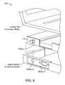
- FIGS. 8-10show exploded, perspective views of portable electronic devices with attachment devices attached thereto.
- FIG. 11shows a system according to an embodiment of the invention.
- Embodiments of the inventionare directed to security apparatuses, methods for making and using such security apparatuses, and systems using such security apparatuses.
- the security apparatusescan be used to prevent or deter the theft of devices such as portable electronic devices.
- One embodiment of the inventionis directed to a security apparatus comprising an attachment device comprising an engagement device having a base including a cap, and also a head (e.g., a “locking head”).
- the headcomprises (i) a housing, (ii) a gate structure within the housing and configured to engage the cap of the base, (iii) a biasing element configured to bias the gate structure toward the cap, and (iv) a locking component inside of the housing.
- a security apparatusmay comprise a head and a security device.
- the head and the security devicemay be physically (e.g. using a pin or other suitable connection) and/or operationally (e.g. wirelessly, etc.) coupled together.
- the security devicemay comprise a cable, or some other type of device to provide security. If the security device comprises a cable, then the cable may be secured to an immovable object such as a desk or cabinet so that a portable electronic device coupled to the cable cannot be removed.
- the cablemay comprise stainless steel, carbon steel, Kevlar®, or some other type of strong material. In exemplary embodiments, the strong material may be chosen to have high tensile strength and/or cut resistance strength.
- the security devicemay comprise a wireless device such as a wireless transmitter and/or receiver.
- the wireless devicemay be used in a proximity detection system or a motion detection system.
- a motion detectorcould present in the wireless device so that when the motion detector moves, an associated alarm is triggered.
- the alarmmay be in the security device or may be external to the security device.
- there may be a base device associated with the wireless deviceand these components may be used in a proximity detection system.
- Wireless signalsmay be transmitted between the security device and the base device, and when these devices are separated by a predetermined distance, an associated alarm (e.g., an audible alarm) may be triggered.
- the alarmcould be in the base device or in the security device.
- the electronics associated with such wireless systemsare known to those of ordinary skill in the art.
- the head in the security apparatusmay be a locking head.
- a locking headmay comprise a locking component (e.g., a locking mechanism) such as a key locking component or a combination locking component disposed within it.
- a “locking component”may comprise one or more structures suitable for causing the head to be in locked and unlocked configurations (i.e., locked or unlocked states).
- locked and unlocked configurationsi.e., locked or unlocked states.
- the portable article that is to be securedmay comprise any suitable article, such as a portable device (e.g., a portable electronic device).
- a portable devicee.g., a portable electronic device
- Examples of such articlescomprise portable computers such laptop, tablet, desktop, and server computers, flat panel televisions, projectors, monitors, portable music players, printers, external hard-drives, cell phones, etc.
- Other types of articlesmay include medical devices that may or may not have electronics in them, industrial devices such as power or pneumatic tools, or sporting goods (bicycles, golf equipment such as golf bags, hockey equipment, etc.).
- the portable article that is to be securedmay be a hand-carried article (i.e., an article capable of carried by a typical user without assistance).
- FIG. 11shows a system comprising a portable article 30 and a security apparatus 26 that is used to secure the portable article 30 to an immovable object 10 such as a desk leg or the like.
- the security apparatus 26comprises a head 28 and a cable 32 coupled to the head 28 , which may be a locking head in this example.
- a loop 34is at a terminal end of the head 28 .
- the cable 32may comprise a strong material such as stainless steel or KevlarTM.
- the cable 32may be wrapped around the immovable object and the head 28 may pass through the loop 34 .
- FIG. 1shows a close up view of parts of a security apparatus according to an embodiment of the invention.
- FIG. 1shows a portable article 30 including a portable article housing 31 comprising an aperture 302 .
- an “aperture”may include a blind aperture or a through aperture.
- a through aperturemay be in the form of a hole, or a recess.
- the aperture 302may be generally rectangular and may have dimensions of about 3 mm by about 7 mm in some embodiments.
- the aperturemay contain a threaded section such as a threaded hole, or may allow outside access (i.e., access from outside of the housing) to a threaded hole, as described in further detail below.
- the aperturemay be non-threaded and be configured to be secured by a non-threaded engagement member such as a T-bar, as described below.
- An attachment device 110may attach to the portable article 30 via the aperture 302 .
- the attachment device 110comprises a base 3 (e.g., a spur) having a flat end opposite a tapered end.
- the base 3can comprise a cap 3 ( a ) and a ring structure 3 ( c ), which define a recess 3 ( b ).
- the cap 3 ( a ) and the ring structure 3 ( c )may have similar diameters.
- the cap 3 ( a ) and the ring structure 3 ( c )may each comprise cylinders with a substantially (axially) tapered end and a substantially flat end opposite the substantially tapered end.
- one or more ends of the cap 3 ( a ) or the ring structure 3 ( c )may comprise a curved surface or other uneven shape (i.e., not flat).
- the lateral side wall of each of the ring structure 3 ( c ) and the cap 3 ( a )may be tapered (as in a cone shape) or may comprise a straight wall.
- the basemay comprise other suitable shapes, such as a block (e.g. a cap having a block shape and a ring structure having a block shape, a rectangular structure, an octagonal shape, etc.
- the cylinders comprising the ring structure 3 ( c ) and the cap 3 ( a )are facing in the same direction. That is, the direction of travel from the flat end of the cap 3 ( a ) to the tapered end of the cap 3 ( a ) is the same direction of travel as from the flat end of the ring structure 3 ( c ) to the tapered end of the ring structure 3 ( c ). That is, the cap 3 ( a ) and the ring structure 3 ( c ) can be axially aligned.
- the recess 3 ( b )can be formed by the space between the tapered end of the ring structure 3 ( c ) and the flat end of the cap 3 ( a ), which may be joined together (and held apart to form the recess) by a central cylinder 3 ( b )- 1 .
- the recess 3 ( b )may be located between the cap 3 ( a ) and the ring structure 3 ( c ).
- the tapered end of the ring structure 3 ( c )may taper from the width of the ring structure 3 ( c ) to the width of the central cylinder 3 ( b )- 1 , at which point the ring structure 3 ( c ) may be joined to the central cylinder 3 ( b )- 1 .
- the cap 3 ( a ) and the ring structure 3 ( c )may have approximately equal lengths, so that the recess is located approximately in the middle of the length of the base 3 .
- the central cylinder 3 ( b )- 1may include a lateral side wall that may be tapered or may comprise a straight wall.
- the cap 3 ( a ), the central cylinder 3 ( b )- 1 , and the ring structure 3 ( c )may be structurally discrete or non-discrete. That is, the cap 3 ( a ), the central cylinder 3 ( b )- 1 , and the ring structure 3 ( c ) may together be formed of one piece of material, such as one machined metal structure with tapered portions and a recess. In another embodiment, each of the cap 3 ( a ), the central cylinder 3 ( b )- 1 , and the ring structure 3 ( c ) may be formed separately, and joined together (such as by glue, rivets, pins, etc.).
- the central cylinder 3 ( b )- 1 and either the cap 3 ( a ) or the ring structure 3 ( c )may comprise one continuous material, which can be joined to the third portion.
- the ring structure 3 ( c ) and the central cylinder 3 ( b )- 1can be formed of a single machined metal part, and then be joined to the cap 3 ( a ) by any suitable process (e.g. glue, rivets, pins, etc.).
- the design of the base of the attachment devicecontains many advantages.
- the basemay conform to the shape of the housing 30 to allow for a secure fit while securing the portable article 30 .
- the flat end of the cap 3 ( a )i.e., the recess-facing end
- the clamping structuree.g. the gates as described below
- the flat end of the cap 3 ( a )can be a substantially planar surface that is approximately 90 degrees from the lateral side wall of the cap 3 ( a ).
- This flat end of the cap 3 ( a )may be approximately parallel to the housing 31 when secured to the slot 302 , and the flat end structure will provide a strong surface for the locking head to hold onto while securing the portable article 30 .
- the locking headis unlikely to be able to slip or be pulled off of the cap 3 ( a ).
- the tapered ends of the cap 3 ( a ) and the ring structure 3 ( c )may assist in guiding the locking head onto the correct position around the base while securing the portable article 30 , resulting in easier locking and unlocking by a user (as described in further detail below).
- the lateral side wall(s) of the attachment device 110may comprise a smooth surface, such as a polished metal surface. This smooth surface can allow a locking head to rotate about the attachment device, preventing a person from twisting the attachment device off of the housing 31 (i.e., forcibly unsecuring the security apparatus) by twisting the locking head.
- an engagement member 1 in the form of a T-barextends axially away from the ring structure 3 ( c ), as shown in FIG. 1 .
- the engagement member 1may comprise other shapes, such as a J-hook (or alternatively an L-hook).
- a coupling element 55 in the form of a screwcan pass through an axial hole (not shown) in the base 3 and into a threaded axial hole (not shown) in the engagement member 1 and can secure the engagement member 1 to the base 3 .
- the end surface of the coupling element 55is flat and can form an end surface of the base of the attachment device 110 .
- the end surface of the coupling element 55can thus comprise a flat portion of the tapered end of cap 3 ( a ).
- the cap 3 ( a )can also cover all lateral edges of the end of the coupling element 55 so that the coupling element cannot be turned by rotation or twisting of the locking head (not shown) that attaches to the attachment device 110 .
- the coupling element 55can entirely cover the tapered end of the cap 3 ( a ).
- the end surface of the coupling element 55may also include a depression or socket 55 ( a ) for receiving an external rotating structure, such as a screwdriver, an end of an Allen wrench, or the like.
- an external rotating structuresuch as a screwdriver, an end of an Allen wrench, or the like.
- the external rotating structuremay comprise a portion or extension of a key for the locking component, and/or the external rotating structure may be integrated or otherwise associated with the coupling element 55 or other portion of the attachment device.
- One or more stabilizing elements 4may be inserted into the aperture 302 to stabilize the attachment device against the housing 31 , so that the engagement member 1 cannot be readily withdrawn from the aperture 302 .
- the T-bar shape of the engagement membercan provide strong security by contacting two opposing sides (e.g., the longer sides such as the sides measuring about 7 mm) of the aperture 302 . This prevents sagging or bulging of the attachment device 110 , such as due to contact with only one side of aperture 302 , as could potentially happen in the case where the attachment device comprises a J-hook (described in further detail below) as an engagement mechanism instead of a T-bar.
- the attachment device 110can be secured to the portable article 30 via the aperture 302 by loosening the coupling element 55 so that the engagement member 1 is able to pass through the aperture 302 .
- the coupling element 55 and the engagement member 1may still be attached to each other.
- the coupling element 55can be tightened so that the engagement member 1 and the base 3 are brought closer together, such that the bottom of the ring structure 3 ( c ) contacts the side surface of the housing 31 of the portable article 30 .
- the attachment device 110 in FIG. 1 and in other embodiments,may have any suitable dimensions.
- the attachment device 110may have dimensions less than about 1 cm 3 or even 0.5 cm 3 .
- the dimensionsmay be substantially equal to or less than about 8 mm ⁇ 6 mm ⁇ 6.5 mm in some embodiments.
- FIG. 2shows the attachment device 110 attached to a portable article 300 .
- the head 120can be secured to the portable article 300 via the attachment device 110 .
- one or more gate structures in the head 120may clamp down on the previously described cap when a locking component in the head 120 is in a locked configuration.
- the head 120may “click” or produce other suitable sounds, to indicate that it has been locked. This can allow for “one click” (or “one step”) fast locking of the head 120 to the attachment device 110 , such as by a single linear motion (e.g., a single linear forward motion) of the head 120 towards the portable article 300 .
- no keymay be necessary to lock the head 120 against the attachment device. Rather, locking of the head 120 may be achieved by the single linear motion (i.e., only “one step” is necessary to lock the head), and a key may only be required to unlock the head 120 .
- FIG. 3Ashows a front perspective, exploded view of parts of a security apparatus including an attachment device 110 , a head 120 , and a key 121 .
- a front hole 4 ( a ) in the head 120is configured to receive a cap 3 ( a ) in the attachment device 110 .
- the head 120may include any suitable dimensions (e.g., 30 mm ⁇ 25 mm ⁇ 12.5 mm) (L ⁇ H ⁇ W).
- FIG. 3Bshows a rear perspective view of the head 120 and the attachment device 110 .
- a keyhole 122is at a rear section of the head 120 .
- the attachment device 110 in FIG. 3Ais different than the attachment device 110 in FIGS. 1 and 2 .
- the specific features of the attachment device 110 in FIGS. 3A and 3Bare described in further detail below.
- FIG. 4Ashows an exploded view of elements of a security apparatus according to embodiments of the invention.
- FIG. 4Ashows an attachment device 110 having a base 2 and an engagement member 1 comprising a central axial hole 1 ( a ).
- the base 2can comprise a ring structure 2 ( a ) (e.g. a lower base), a central axial hole 2 ( b ), and a cap element 3 comprising a cap 3 ( a ) and a rod 3 ( d ) extending axially from a center of the cap 3 ( a ).
- the ring structure 2 ( a )is between the cap 3 ( a ) and the end of the engagement member 1 .
- the rod 3 ( d )extends axially through the hole 2 ( b ) in the base 2 , and into the hole 1 ( a ) in the engagement member 1 .
- An end of the rod 3 ( d )may be threaded so that it is complementary to a threaded hole 1 ( a ) in the engagement member 1 .
- the engagement membermay comprise a J-hook, a T-bar, a threaded post, or other suitable shape.
- the head 120comprises a first housing portion 4 comprising a hole 4 ( a ), and a second housing portion 15 , which are coupled together with assembly pins 5 ( a ), 5 ( b ), 8 ( a ), 8 ( b ) to form a housing.
- a ferrule 17is coupled (in certain embodiments, rotatably coupled) to the first housing portion 4 using a hinge pin 16 .
- the ferrule 17may comprise a multi joined cable ferrule, to allow for easy securing of the head 120 from any orientation.
- the multi joined ferrule 17may comprise two or more hinges, or may comprise a hinge connecting an outer ferrule portion to an inner ferrule portion. This inner ferrule portion may, in turn, rotatably connect to the first housing portion 4 .
- a cable(not shown) can be connected to the ferrule 17 .
- the housing of the head 120may comprise one or several pieces.
- the head 120can also have a number of internal components.
- the head 120can include a securing element, to securely attach to the attachment device.
- a “securing element”may comprise one or more structures to actively engage a fixed member in a locked position (i.e., one or more structures for securing a head to an attachment device).
- a securing element in the head 120may comprise a gate assembly 7 .
- First and second opposed gate structures 7 ( a ), 7 ( b ) forming the gate assembly 7can be at a front region of the head 120 .
- first and second opposed gate structures 7 ( a ), 7 ( b )can be configured to engage a base of an attachment device, such as by inwardly clamping onto a recess in the base while the head 120 is in a locked configuration. While in this configuration, the first and second gates structures 7 ( a ), 7 ( b ) may be biased towards the base (e.g., biased inwards and towards each other).
- the first and second gate structures 7 ( a ), 7 ( b ),can form a cavity which can fully surround the base of an engagement member.
- the base of the attachment devicemay be inaccessible to users (due to being entirely located within the gate assembly cavity and being fully surrounded by the head).
- the gate assemblymay be similarly inaccessible to users, as it can be fully surrounded by the housing of the head 120 , preventing unauthorized movement of the gates by hand or using lock-picking tools.
- the head 120may have other securing elements, such as ball bearings, one or more internal adjustable wrenches, clamps, adjustable belts, etc.
- the head 120may not require biasing elements for the securing element (i.e., the securing element may engage a fixed member without the use of biasing elements).
- the securing elementmay comprising a selectively deformable material for receiving an attachment device, piezoelectric material, hinges, etc.
- a lock plate 9comprising a central hole 9 ( a ) lies between the first and second gate structures 7 ( a ), 7 ( b ) and at least a portion of an actuator and lock holder assembly 10 .
- the actuator and lock holder assembly 10may comprise an actuator 10 ( b ) in the form of a cam which extends forward from a lock holder assembly 10 ( a ).
- the actuator 10 ( b )may comprise a cam follower, an eccentric follower, an eccentric cam, a T-bar shaped structure, or other suitable structure.
- the actuator 10 ( b )passes through the central hole 9 ( a ) of the lock plate 9 .
- a locking component 12 in the form of a disk locking component comprising a number of disks 13 and a lock pin 11is housed in the lock holder assembly 10 ( a ).
- Another lock plate 14is at a rear region of the head 120 .
- FIG. 4it is understood that other types of locking components (e.g., a tumbler and pin locking component) can be used in other embodiments of the invention.
- first and second gate structures 7 ( a ), 7 ( b )provide for a number of advantages. This configuration is better than providing only one gate structure or ball bearings as a securing mechanism. While an embodiment with one gate structure would be acceptable, it can be potentially easier to disengage a locking head from an attachment device when only one gate structure or ball bearings are used in the locking head. For example, an unauthorized user can try and disengage the locking head from an attachment device by pulling the cable attached to the locking head away from the attachment device in an axial direction, while tapping the locking head in a radial direction with a small hammer or the like.
- FIG. 4Bshows an exploded view of a security head 120 -A according to an implementation of the invention.
- the embodiments shown hereincan provide “keyless locking” as disclosed above (i.e., one step locking) with high security and reduced likelihood of lock error (e.g. binding of the gates, etc.).
- the head 120 -Acomprises a first housing portion 41 , such as a cable ring, comprising a hole 41 ( a ), and a second housing portion 412 , which are coupled together with assembly pins 42 to form a housing.
- a ferrule 414 ( a )is rotatably coupled to the first housing portion 41 using one or more hinge pins 413 .
- the hinge pins 413 and portions of the first housing portion 41may be covered by a ring cap 415 , for security.
- the ferrule 414 ( a )can be rotatably connected to a swivel adapter 416 of a swivel ferrule 414 ( b ) (e.g., a multi jointed ferrule), to allow for easy securing of the head 120 from any orientation.
- the swivel ferrule 414 ( b )can in turn comprise a first swivel portion 418 ( a ) and a second swivel portion 418 ( b ), connected by a hinge pin 417 .
- a cable(not shown) can be connected to the swivel ferrule 414 ( b ).
- the housing of the head 120may comprise one or several pieces.
- the head 120 -Acan also have a number of components inside of the housing or otherwise associated with the housing.
- one or more componentsmay be operationally coupled to, or outside of, the housing.
- the head 120 -Acan include a securing element, such as a gate assembly 44 , to securely attach to the attachment device.
- First and second opposed gate structures 44 ( a ), 44 ( b ) forming the gate assembly 44can be at a front region of the head 120 . In the absence of other external forces, they are biased inwardly by spring 43 (examples of biasing elements), which is located between the first housing portion 41 and the first gate structure 44 ( a ).
- one gatee.g.
- second gate structure 44 ( b ))may remain fixed while the other gate (e.g. first gate structure 44 ( a )) moves inwardly and outwardly.
- both first and second gate structures 44 ( a ), 44 ( b )can move inwardly and outwardly, and the gate assembly 44 may be biased by both spring 43 and a second spring (not shown).
- the head 120 -Amay have other securing elements, such as ball bearings, one or more internal adjustable wrenches, clamps, adjustable belts, etc.
- a lock plate 46comprising a central hole 46 ( a ) lies between the gate assembly 44 and at least a portion of an actuator and lock holder assembly 47 .
- the lock plate 46may be held in place (e.g., coupled) with respect to the second housing portion 412 by one or more assembly pins 45 .
- the actuator and lock holder assembly 47may comprise an actuator 47 ( b ) in the form of a cam which extends forward from a lock holder assembly 47 ( a ).
- the actuator 47 ( b )(which may have forms other than a cam as shown in FIG. 4B ) passes through the central hole 46 ( a ) of the lock plate 46 .
- a locking component 49 in the form of a disk locking component comprising a number of disks 410is housed in the lock holder assembly 47 ( a ).
- a lock pin 48may be disposed in a slot within the lock holder assembly 47 ( a ).
- Another lock plate 411is at a rear region of the head 120 .
- FIG. 4Bit is understood that other types of locking components (e.g., a tumbler and pin locking component), or other configurations of disk locking components, can be used in other embodiments of the invention.
- the attachment devices, as well as parts of the locking heads, shown hereinmay be made of any suitable materials, including zinc, stainless steel or nickel alloys. Furthermore, as the attachment device can be made small (while providing superior security strength), the lock head itself may be configured small, to allow for greater portability by the user.
- FIGS. 5A-5Fshow various views of certain embodiments of attachment devices.
- FIG. 5Ashows an outside side view of an embodiment of an attachment device comprising J-hook.
- the attachment devicemay have a base 3 , which includes a ring structure 2 and a cap 3 ( a ).
- the ring structure 2 of the attachment devicemay also include a large portion 2 ( a )- 1 and a relatively smaller portion 2 ( a )- 2 .
- the large portion 2 ( a )- 1 , the smaller portion 2 ( a )- 2 , and the cap 3 ( a )may form a circumferential recess that can receive a gate structure.
- the cap 3 ( a )can include a number of ridges 3 ( a )- 1 so that a user can grip it and turn it.
- FIG. 5Bshows a side cross-sectional view of an embodiment of an attachment device comprising a T-bar.
- an embodiment of the attachment device 140may comprise a base 600 (e.g., a spur) connected to an engagement member 700 .
- the base 600can include a cap 600 ( a ) and a ring structure 600 ( c ) which can define a recess 600 ( b ) in the base 600 .
- the recess 600 ( b )can comprise a trench or channel that extends the entire diameter of the base, or the recess 600 ( b ) can comprise one or more discrete indentations (e.g., divots, trenches, etc.) in the base.
- the recess 600 ( b )can be configured to receive a securing element of a locking head.
- the securing elementmay comprise, for example, a gate assembly as described herein.
- the securing elementmay be coupled to the head, by extending portions of the securing element into the recess 600 ( b ). This can prevent removal of the locking head from the attachment device, without first unlocking the securing element.
- a coupling element 650such as a screw, can extend at least partly through a central opening of the base 600 .
- the engagement member 700may comprise a T-bar shape.
- the T-bar shapemay have suitable dimensions for securely attaching to a portable article.
- a bottom view cross-section of the T-barmay have a width of about 2.4 mm, and a length of about 6.4 mm.
- the T-bar shape of the engagement member 700may provide about 6.7 mm 2 of contact surface area with the inside of the housing.
- the coupling element end 650 ( b )may comprise a threaded screw, which engages a threaded hole in the engagement member 700 .
- rotating the coupling element 650using, for example, a hex key
- the T-bar shape of engagement member 700may then be pulled towards the inside of the housing of a portable article, clamping the housing between the T-bar extensions of the engagement member 700 and the flat end of the ring structure 600 ( c ) (i.e., the housing is clamped between the engagement member 700 and the base 600 ).
- clamping padsmay extend from the flat end of the ring structure 600 ( c ), so that the attachment device 140 may be secured to the portable article by compressing the housing between the clamping pads and the engagement member 700 .
- FIG. 5Cshows an exploded perspective view of an embodiment of an attachment device comprising a thumbscrew as a coupling element, and a J-hook.
- the attachment devicecan comprise a base 52 a coupled to an engagement member 51 a in the form of a J-hook.
- the attachment devicecan also comprise a thumbscrew 55 a with an integrated coupling element (e.g., a rod), for loosening and tightening the engagement member 51 a .
- a washer 54 acomprising rubber or other suitable material such as a soft metal
- a biasing element 53 asuch as a compression spring
- FIG. 5Dshows an exploded perspective view of an embodiment of an attachment device comprising a screw as a coupling element, and a J-hook as an engagement member.
- the attachment devicecan comprise a base 52 b coupled to an engagement member 51 b in the form of a J-hook.
- the attachment devicecan also comprise a coupling element 53 b , such as a socket head cap screw, for loosening and tightening the engagement member 51 b .
- the threaded post portion of the coupling element 53 bcan extend through the center of the base 52 b , to threadedly couple to a threaded hole (not shown) within engagement member 51 b.
- FIG. 5Eshows an exploded perspective view of an embodiment of an attachment device comprising a screw as a coupling element, and a T-bar as an engagement member.
- the attachment devicecan comprise a head 52 c coupled to an engagement member 51 c in the form of a T-bar.
- the attachment devicecan also comprise a coupling element 53 c , such as a socket head cap screw, for loosening and tightening the engagement member 51 c .
- the threaded post portion of the coupling element 53 ccan extend through the center of the base 52 c , to threadedly couple to a threaded hole 51 c - 1 within engagement member 51 c .
- rotating the coupling element 53 cmay slide the engagement member 51 c inwardly and outwardly from the base 52 c.
- FIG. 5Fincluding FIGS. 5F-1 through 5 F- 5 , various views are shown of exemplary attachment devices 130 ( a ) and 130 ( b ), each secured to a portable article housing 30 .
- FIG. 5F-1shows a top perspective view of an attachment device 130 ( a ) using a T-bar shaped engagement member, and an attachment device 130 ( b ) using a J-hook shaped engagement member.
- Other embodiments of attachment devices with other engagement member implementationse.g. a screw, etc.
- FIG. 5F-2shows an overhead view of the attachment devices 130 ( a ) and 130 ( b ).
- the diameter of the base 800 ( a ) or 800 ( b ) of the attachment device 130 ( a ) or 130 ( b )may each comprise about 8 mm at its maximum lateral dimension.
- “maximum lateral dimension” of a structuremay comprise the dimension of the structure at its widest point as measured laterally (the innermost surface defining the recess in the base 800 ( a ) or 800 ( b ) may have a lateral dimension less than the maximum lateral dimension).
- the maximum lateral dimensioncomprises a diameter.
- the maximum lateral dimensionmay comprise a lateral width.
- the maximum lateral dimension (e.g., maximum diameter) of the base 800 ( a ) or 800 ( b )may be at most about 8 mm in some embodiments.
- Certain examples of the bases 800 ( a ), 800 ( b )may have lateral dimensions up to about 8 mm, including within the range of 6 mm to 8 mm.
- Other examples of the base 800 ( a ) or 800 ( b ), according to embodiments of the inventionmay have lateral dimensions of about 6-10 mm.
- Still another implementationmay have a lateral dimension of less than 11 mm (e.g. 10.9 mm, 7.5 mm, 8 mm, etc.).
- FIG. 5F-3a cutaway side view of attachment device 130 ( a ) and 130 ( b ) is shown.
- the base 800 ( a ) of the attachment device 130 ( a ), and the base 800 ( b ) of the attachment device 130 ( b )each extend past the housing 30 by a certain height.
- Embodiments of the bases 800 ( a ), 800 ( b )may each have a height of approximately 7 mm (e.g., 7.35 mm).
- the “height” of the basemay comprise the amount the base would extend from a housing that the respective attachment device is secured to.
- the heightcan comprise the distance from the flat end of the ring structure 800 ( a )-( 2 ) to the outside edge (e.g., the flat portion) of the tapered end of cap 800 ( a )- 1 of the base 800 ( a ).
- the base 800 ( a ) or 800 ( b )may have a height of between approximately 6.5 mm to approximately 8.5 mm.
- the base 800 ( a ) or 800 ( b )may have a height of less than approximately 11 mm (e.g. 10.5 mm, 8.3 mm, etc.).
- the basemay have a height of at most about 7.5 mm.
- FIG. 5F-4shows side and bottom views of attachment devices 130 ( a ), 130 ( b ), each attached to a housing 30 .
- the engagement member 810 ( a ) of attachment device 130 ( a )is in the form of a T-bar, and has been rotated and pulled inwardly to securely attach the attachment device 130 ( a ) to the housing 30 .
- the engagement member 810 ( b ) of attachment device 130 ( b )is in the form of a J-hook, and has been pulled inwardly to securely attach the attachment device 130 ( a ) to the housing 30 .
- 5F-5shows side views and the bottom views of attachment devices 130 ( a ), 130 ( b ), to highlight the contact surface area of each engagement member 810 ( a ), 810 ( b ).
- the engagement member 810 ( a )may have a contact surface area with the housing 30 of approximately 7 square mm.
- the engagement member 810 ( b )may have a contact surface area with the housing 30 of approximately 10.2 square mm.
- Other embodiments hereinmay contemplate difference contact surface area sizes.
- FIG. 5Gshows an embodiment of an attachment device 730 ( b ) including an engagement member 701 having a J-hook shape.
- Other embodiments of the attachment device 730 ( b )may comprise other shapes, such as a T-bar.
- the base 702may include a ring structure 702 ( c ), a recess 702 ( b ), a cap 702 ( a ), and a coupling element 703 comprising a thumbscrew.
- the coupling element 703may include a threaded post (e.g., a threaded rod) that extends through the base 702 and into a threaded hole (not shown) within engagement member 701 .
- a threaded poste.g., a threaded rod
- the top portion of the coupling element 703can be turned, such as by hand. This can draw the engagement member 701 into the base 702 , to clamp the attachment device 730 ( b ) against the housing of the portable article.
- the attachment devicemay use a screw or other coupling element to engage with a portable article, which can be configured to receive a wrench or other external rotating structure.
- FIG. 5Hshows an embodiment of an attachment device 730 ( a ) including an engagement member 711 having a T-bar shape.
- Other embodiments of the attachment device 703 ( a )may comprise other shapes, such as a J-hook.
- the base 702may include a coupling element 713 comprising an allen screw.
- the coupling element 713may include a threaded post that extends through the base 712 and into a threaded hole (not shown) within engagement member 711 .
- the attachment device 730 ( a )may be rotated so that the stabilizing element(s) 715 are also disposed within the aperture. Then, the top portion of the coupling element 713 can be turned, such as by using an external rotating structure 720 (an alien wrench) engaged with socket 713 ( a ) within the coupling element 713 . This can draw the engagement member 711 into the base 712 , to clamp the attachment device 730 ( a ) against the housing of the portable article.
- an external rotating structure 720such as a wrench
- the attachment devicemay include a recess 776 that has a substantially rectangular profile (e.g., when viewed from the side). This is shown in FIGS. 5I-5K .
- the attachment devicecan have a maximum width W of about 8 mm.
- the spacing between the two ring structures (e.g., the cap and the ring structure) defining the recesscan have a maximum outer distance of about 7.35 mm.
- the coupling element 773can pass through an aperture in the base 772 and may couple to a T-bar 771 .
- 5I-5Kcan have an axial pull strength of greater than about 125 lbs, such as greater than about 490 lbs, even though the dimensions of the attachment device that would extend outside of the housing of a portable electronic device would be less than about 8 mm ⁇ 8 mm. Such results are surprising and unexpected.
- the attachment devicemay be formed by a metal injection molding (MIM) process.
- MIMmetal injection molding
- This MIM processcomprises mixing fine metal powders with thermoplastic binders, then kneading the mixture using a high shear rate kneader. After kneading, the homogeneous feedstock can be pelletized to facilitate loading into a molding machine.
- the mixturecan be injected into the molding machine, to form green parts.
- the debinding stepwhere the binder material is extracted from the green parts, leaving the formed product (i.e., the attachment device or portions thereof) comprising only the metal.
- the formed productis sintered (i.e., held at high temperature to attain the required mechanical and physical properties).
- the productcan be finished, such as by plating, sand blasting, drilling, tapping, heat treating, Teflon coating, phosphating, machining, etc.
- the parts of the attachment devicemay comprise a steel comprising at least one of iron (Fe), nickel (Ni), molybdenum (Mo), and carbon (C).
- the materials used in the MIM process described abovecan comprise MIM4605 metal.
- the “MIM4605” metalis made of approximately 0.5% carbon (C), approximately 2% nickel (Ni), approximately 0.5% molybdenum (Mo), with the balance (approximately 97%) comprising iron (Fe).
- the MIM4605 metalcan have a density greater than 7.5 g/cm 3 , a tensile strength of 1,655 MPa, an elongation ability of 20%, and a hardness of 48 HRC (Rockwell “C” scale).
- MIM4605 that is only sintered, and not further heat treatedmay have a density greater than 7.5 g/cm 3 , a tensile strength of 440 MPa, an elongation ability of 15%, and a hardness of 62 HRB (Rockwell “B” scale).
- MIM4605may be heat treated to have a hardness of 30 HRC.
- a hardness with a value lower than 48 HRCis desirable in some embodiments.
- the attachment devicemay comprise MIM4605 metal, heat treated to a hardness of 30 HRC.
- the attachment devicemay have a hardness in the range of 20 to less than 48 HRC.
- the attachment devicemay be heat treated to have a hardness of approximately 25 to 35 HRC.
- the attachment device, or portions thereofmay be heat treated to have a hardness of approximately 28 to 32 HRC.
- various heat treating methodsincluding heating and subsequent cooling procedures
- Attachment devices treated to have such a hardnesshave been determined to provide suitable security characteristics. That is, an attachment device with a hardness of approximately 30 HRC will have good balance between ductility and brittleness. This attachment device will be both strong enough to resist pulling apart, while ductile enough to prevent shattering upon receiving forceful blows (e.g., being hit with a hammer, etc.). As such, a portable article secured with an attachment device as described herein will be exceedingly difficult to remove by force.
- the attachment device(including the base and the engagement member) may be of a reasonable size, as compared to the previously connectors. Due to the shape and construction as described herein, the attachment device may be manufactured smaller than prior art structures, but may have equal to or greater security strength.
- the attachment devices according to embodiments of the inventioncan withstand an axial pulling force of greater than about 125, 200, 300, 400, and even 500 lbs before breaking.
- the pull testmay comprise securing the attachment device to a steel plate (or a part of the portable article to be secured, such as to a chassis or a housing of the portable article) and pulling (e.g., pulling at a 90 degree angle from the steel plate) the attachment device until it breaks.
- the attachment devicemay be constructed so it does not protrude far (or at all) from the edge of the housing of the portable article while being attached.
- the attachment devices shown hereinare very user friendly. Still, the attachment device as disclosed herein can be secured to the portable article with sufficient strength so that it cannot be easily pulled, twisted, or otherwise removed.
- a method for using the security apparatusmay comprise: obtaining a portable article, and an attachment device attached to the portable article; and attaching a head to the attachment device, wherein the head comprises (i) a housing, (ii) a gate structure (or other suitable securing element) within the housing and configured to engage the base of the attachment device, (iii) a biasing element configured to bias the gate structure toward the base, and (iv) a locking component inside of the housing.
- the locking componentcan be in a locked configuration after the base is attached to the attachment device (without requiring a key).
- the attachment device 110can be first secured to a portable article as described above.
- the head 120can be positioned toward the security device 110 such that the hole 4 ( a ) in the first housing portion 4 of the head 120 is aligned with the cap 3 ( a ).
- the springs 6 ( a ), 6 ( b )bias the first and second gate structures 7 ( a ), 7 ( b ) inward in the absence of outward pressure.
- Each gate structure 7 ( a ), 7 ( b )may have a front wall portion 7 ( a )- 1 , 7 ( b )- 1 , a rear wall portion 7 ( a )- 2 , 7 ( b )- 2 and a bridging portion 7 ( a )- 3 , 7 ( b )- 3 . These portions may define a recess which can house a corresponding spring 6 ( a ), 6 ( b ).
- each front wall portion 7 ( a )- 1 , 7 ( b )- 1may have an inward sloped surface 7 ( a )- 1 ′, 7 ( b )- 1 ′, which allows the cap 3 ( a ) (e.g., the forward portion of the base) to push the gate structures 7 ( a ), 7 ( b ) radially outward as the cap 3 ( a ) passes axially into the hole 4 ( a ), thereby compressing the springs 6 ( a ), 6 ( b ).
- the cap 3 ( a )e.g., the forward portion of the base
- the gate structures 7 ( a ), 7 ( b )clamp down on it, and it cannot be withdrawn from the head 120 .
- the springs 6 ( a ), 6 ( b )bias the first and second gate structures 7 ( a ), 7 ( b ) towards the base, so that the front wall portions 7 ( a )- 1 , 7 ( b )- 1 of the gate structures 7 ( a ), 7 ( b ) prevent withdrawal of the attachment device 110 from the locking head 120 .
- the locking component in the head 120 in FIGS. 6A and 6Bis in a locked configuration, and the head 120 cannot be separated from the security device 110 unless an authorized key is used.
- FIGS. 7A-7Bshow how the head 120 can be separated from the attachment device 110 .
- an authorized key(not shown) is inserted into the head 120 to unlock the locking component 12 in the head 120 .
- the keycan thus turn the actuator 10 ( b ) (e.g., clockwise in FIG. 7B ) such that protrusions 7 ( a )- 4 , 7 ( b )- 4 in the first and second gate structures 7 ( a ), 7 ( b ) are engaged and are pushed outward.
- the front wall portions 7 ( a )- 1 , 7 ( b )- 1 of the first and second gate structures 7 ( a ), 7 ( b )no longer obstruct the cap 3 ( a ) from being separated from the head 120 .
- FIG. 7Bshows the first and second gate structures 7 ( a ), 7 ( b ) may each have an “L” shape, and may overlap with portions of each other along the sides of the device. This can allow for reliable operation.
- Embodiments of the locking heads as disclosed hereinprovide for improved methods of locking and unlocking.
- no keymay be necessary to lock the head against the attachment device.
- the locking headmay be capable of securing to the attachment device upon a single movement of the locking head, using the securing element.
- the headmay be secured to the attachment device such that the locking head (e.g., the locking component) is in a locked configuration (i.e., a secured configuration, while secured to the attachment device) without the use of a key; rather, only a single motion (e.g. a single linear motion, a single rotational motion, etc.), such as sliding the attachment device toward the base may be used.
- a single motione.g. a single linear motion, a single rotational motion, etc.
- the locking headmay be in a locked configuration upon a single movement of the locking head.
- the headmay indicate it is then in the locked configuration by producing a sound, such as a “click.”
- the locking heads disclosed hereinare therefore quite user friendly. Less effort is required to secure a portable article, and a user may be assured that the locking head is properly in place.
- FIGS. 8-10show various ways in which an attachment device can be secured to a portable article.
- the portable article 300may include a housing having a top enclosure 300 ( a ) and a bottom enclosure 300 ( b ), and also an internal chassis 300 ( c ) within the housing 300 ( a ), 300 ( b ).
- the bottom enclosure 300 ( b )may include a cavity 300 ( b )- 1 , and a hole 300 ( b )- 2 within the cavity 300 ( b )- 1 .
- the hole 300 ( b )- 2may expose a portion of the chassis 300 ( c ). As shown in FIG.
- the attachment device 110may be molded and/or integral with the internal (metal) chassis 300 ( c ), and may pass through the second hole 300 ( b )- 2 in the bottom enclosure 300 ( b ).
- the attachment device 110 DOOM the hole 300 ( b )- 2 , and the cavity 300 ( b )- 1may be configured so that the attachment device 110 does not extend past the edge of the housing. In other embodiments, the attachment device 110 may only slightly extend past the edge of the housing, such as by at most about 3 mm. This can prevent the attachment device 110 from being awkwardly placed or otherwise provide an undesirable protrusion from the portable article.
- FIGS. 9A and 9Bis similar to FIG. 8 , except that the attachment device 110 has an engagement member comprising a threaded post 110 ( a ), which is secured to a hole 300 ( c )- 1 (e.g, a threaded hole) in the internal chassis 300 ( c ).
- the attachment device 110may pass through a hole 300 ( b )- 2 in the bottom enclosure 300 ( b ).
- the holes 300 ( b )- 2 and 300 ( c )- 1may each comprise a threaded or non-threaded hole.
- the hole 300 ( b )- 2may be aligned with the hole 300 ( c )- 1 in the chassis 300 ( c ), and may expose a portion of the chassis 300 ( c ).
- the attachment device 110may be threadably engaged with the threaded hole 300 ( c )- 1 , in order to be attached to the portable article.
- the threaded post 110 ( a ) attached to the base of the attachment device 110can also be threadably engaged with a threaded hole 300 ( b )- 2 in the housing of the portable article 300 .
- the cavity 300 ( b )- 1may surround the hole 300 ( b )- 2 , and both the cavity 300 ( b )- 1 and the hole 300 ( b )- 2 may be formed (such as by molding or other suitable process) in the housing.
- the outside end of the attachment devicemay comprise a tapered end having a smooth surface, to prevent the device from snagging or otherwise troubling a user.
- the hole 300 ( b )- 2may not be threaded, and may have a diameter equal to or greater than the diameter of the base of the attachment device 110 .
- the attachment devicemay reside within the hole 300 ( b )- 2 and also within the cavity 300 ( b )- 1 while being attached to the chassis 300 ( c ). This can allow the attachment device to be securely attached to the portable article, without extending past (or much past, e.g. at most 3 mm) the edge of the housing of the portable article.
- the attachment devicecan comprise a single screw (e.g., only one screw) that attaches to the chassis 300 ( c ).
- the attachment devicecan directly contact the chassis, as the threaded post 110 ( a ) can threadably engage directly with the hole 300 ( c )- 1 , for greater security.
- the attachment device 110Because part of the attachment device 110 , and in particular, the ring structure, is both cooperatively structured with and within the hole 300 ( b )- 2 , the attachment device 110 is secured in such a way that the lateral movement of the attachment device 110 relative to the housing is difficult, thus enhancing the security of the apparatus. Further, as noted above, the attachment device 110 does not protrude outwardly from the housing very far, thus making the use of the attachment device 110 palatable to both consumers and manufacturers.
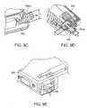
- FIGS. 9C-9Eshow internal and external displacements of an attachment device 110 that is attached to a housing of a portable article 300 , according to an embodiment of the invention.
- FIG. 9Cshows a view of the outside back portion of a portable article 300
- FIG. 9Dshows a side section view of the portable article 300
- FIG. 9Eshows a view of the side portion of a portable article 300 .
- the internal displacement of the attachment device 110specifically the threaded post 110 ( a ), as shown by the A ⁇ B ⁇ C marked lengths, can comprise about 4 mm ⁇ 4.5 mm ⁇ 4.5 mm.
- the outside area of the portable article 300 that could be used for the attachment device 110can comprise 13 mm ⁇ 22 mm, based on the centered axis of the hole 300 ( c )- 1 .
- Embodiments described hereincan thus provide enhanced security while using a reduced footprint. As portable articles, such as a computers, continue to get smaller, space becomes more precious. Embodiments disclosed herein can advantageously provide security without impinging on other features of the secured portable articles, and are small enough to work well with products not yet produced, even as such products shrink.
- the chassis 300 ( c ) of the portable articlecan be built with a drop in slot 390 , which is configured to receive an attachment device 110 with a body 110 ( b ) and a groove 110 ( c ).
- the body 110 ( b )can fit within the slot 390 , such that the top enclosure 300 ( a ) will prevent the attachment device 110 from being removed from the slot 390 .
- Embodiments of the inventionhave a number of advantages.
- the attachment device according to embodiments of the inventioncan be attached to an aperture in a portable article, or it may be attached to another part of the portable article. Further, the head including the locking component can be attached to the attachment device with a single motion, thus making it easier for a user to use. Also, because the attachment device can be small, it can be used with most commercially available thin portable articles such as laptop computers.
- embodiments of the inventionadvantageously provide for greater strength than other conventional locking systems, while being smaller in size.
- Embodiments of the inventionwere tested for strength.
- the axial pull strength of an attachment device of the type shown in FIG. 5G attached to a substantially rectangular slot in a steel plate about 4 mm thickwas evaluated. Thirty samples were subjected to an axial pulling force.
- the thumbscrewhad an M2 screw, a zinc die case spur body, and a J-hook made of an MIM (metal injection molding) material.
- the average tensile force required to break the attachment devicewas 125 lbs.
- the axial pull strength of an attachment device of the type shown in FIG. 5D attached to a substantially rectangular slot in a steel plate about 4 mm thickwas evaluated. Ten samples were subjected to an axial pulling force in a static load test.
- the attachment devicehad an M2 screw comprising 18-8 Stainless Steel, a zinc die case spur base, and a J-hook made of an MIM (metal injection molding) material (MIM4605).
- MIM4605 materialwas sintered but not further heat treated.
- the M2 screwcomprised an M2 ⁇ 0.4 mm Socket Head Cap Screw.
- the average tensile force required to break the attachment devicewas about 280 lbs.
- the thumbscrewwas replaced with an M2 ⁇ 0.4 mm socket head cap screw.
- the attachment devicecan use an Allen key to tighten the screw. More torque force can be applied through the key.
- the axial pull strength of an attachment device of the type shown in FIG. 5E attached to a substantially rectangular slot in a steel plate about 4 mm thickwas evaluated. Five samples were subjected to an axial pulling force from a static load test.
- the attachment devicehad an M2 screw comprising a high strength 12.9 class screw, an MIM4605 spur body, and a T-bar (comprising MIM4605).
- the average tensile force required to break the attachment devicewas about 410 lbs.
- the slot attachment J-hookwas replaced with a T-bar made of M4605 metal as described herein.
- the T-bar metalwas not further heat treated beyond sintering.
- the axial pull strength of an attachment device of the type shown in FIGS. 5I , J, and K attached to a substantially rectangular slot in a steel plate about 4 mm thickwas evaluated. Eight samples were subjected to an axial pulling force at a pull speed in a static load test.
- the attachment devicehad an M2 screw comprising a high strength 12.9 class screw that has been heat treated and tempered, an MIM4605 base, and a T-bar (MIM4605, hardened to 30 Rockwell C).
- the average tensile force required to break the attachment devicewas 490 lbs.
- the screwhad modified heat treating and tempering, and the T-Bar material was hardened, to achieve higher tensile strength. Furthermore, the recess profile was modified to have a substantially rectangular profile as described above, which further improved the tensile strength.
- any embodimentmay be combined with one or more features of any other embodiment without departing from the scope of the invention.
- embodiments hereinalso contemplate the exact measurement.
- a shapesuch as a cylinder
- embodiments hereincontemplate other suitable shapes, such as multi-sided blocks (octagonal structures, decagonal structures, etc.), other rectangular structures, etc.
- structures with multiple sides approaching the shape of cylinders, as well as substantially cylindrical shapesmay be considered cylinders as described herein, unless otherwise specified.
Landscapes
- Engineering & Computer Science (AREA)
- Computer Hardware Design (AREA)
- Casings For Electric Apparatus (AREA)
- Burglar Alarm Systems (AREA)
- Hooks, Suction Cups, And Attachment By Adhesive Means (AREA)
Abstract
Description
| TABLE 1 | |||
| Sample | Test Result (lbs) | ||
| 1 | 136.4 | ||
| 2 | 171.6 | ||
| 3 | 382.8 | ||
| 4 | 308.0 | ||
| 5 | 267.3 | ||
| 6 | 299.2 | ||
| 7 | 303.8 | ||
| 8 | 336.6 | ||
| 9 | 348.0 | ||
| 10 | 338.1 | ||
| Average | 289.4 | ||
| TABLE 1 | |||
| Sample | Test Result (lbs) | ||
| 1 | 372.0 | ||
| 2 | 447.0 | ||
| 3 | 399.3 | ||
| 4 | 370.4 | ||
| 5 | 472.9 | ||
| Average | 412.3 | ||
| TABLE 3 | |||
| Sample | Test Result (lbs) | ||
| 1 | 440.0 | ||
| 2 | 534.3 | ||
| 3 | 460.8 | ||
| 4 | 491.8 | ||
| 5 | 551.2 | ||
| 6 | 515.5 | ||
| 7 | 506.2 | ||
| 8 | 471.9 | ||
| Average | 496.5 | ||
Claims (20)
Priority Applications (5)
| Application Number | Priority Date | Filing Date | Title |
|---|---|---|---|
| US12/969,401US7997106B2 (en) | 2009-05-29 | 2010-12-15 | Security apparatus including locking head and attachment device |
| PCT/US2011/051602WO2012047467A2 (en) | 2010-09-27 | 2011-09-14 | Security apparatus including attachment device |
| EP11831168.7AEP2622528A4 (en) | 2010-09-27 | 2011-09-14 | Security apparatus including attachment device |
| TW100134143ATWI551764B (en) | 2010-09-27 | 2011-09-22 | Security apparatus including attachment device |
| TW100217779UTWM440468U (en) | 2010-09-27 | 2011-09-22 | Security apparatus including attachment device |
Applications Claiming Priority (4)
| Application Number | Priority Date | Filing Date | Title |
|---|---|---|---|
| US18259109P | 2009-05-29 | 2009-05-29 | |
| PCT/US2010/036628WO2010138847A2 (en) | 2009-05-29 | 2010-05-28 | Security apparatus including attachment device |
| US12/891,707US20110061427A1 (en) | 2009-05-29 | 2010-09-27 | Security apparatus including attachment device |
| US12/969,401US7997106B2 (en) | 2009-05-29 | 2010-12-15 | Security apparatus including locking head and attachment device |
Related Parent Applications (1)
| Application Number | Title | Priority Date | Filing Date |
|---|---|---|---|
| US12/891,707ContinuationUS20110061427A1 (en) | 2009-05-29 | 2010-09-27 | Security apparatus including attachment device |
Publications (2)
| Publication Number | Publication Date |
|---|---|
| US20110072863A1 US20110072863A1 (en) | 2011-03-31 |
| US7997106B2true US7997106B2 (en) | 2011-08-16 |
Family
ID=43223383
Family Applications (6)
| Application Number | Title | Priority Date | Filing Date |
|---|---|---|---|
| US12/891,707AbandonedUS20110061427A1 (en) | 2009-05-29 | 2010-09-27 | Security apparatus including attachment device |
| US12/969,401ActiveUS7997106B2 (en) | 2009-05-29 | 2010-12-15 | Security apparatus including locking head and attachment device |
| US12/977,486ActiveUS8001812B2 (en) | 2009-05-29 | 2010-12-23 | Security apparatus including locking head |
| US12/987,000ActiveUS8042366B2 (en) | 2009-05-29 | 2011-01-07 | Security apparatus including attachment device |
| US13/306,534AbandonedUS20120125057A1 (en) | 2009-05-29 | 2011-11-29 | Security apparatus including attachment device |
| US14/839,081AbandonedUS20150368932A1 (en) | 2009-05-29 | 2015-08-28 | Security apparatus including attachment device |
Family Applications Before (1)
| Application Number | Title | Priority Date | Filing Date |
|---|---|---|---|
| US12/891,707AbandonedUS20110061427A1 (en) | 2009-05-29 | 2010-09-27 | Security apparatus including attachment device |
Family Applications After (4)
| Application Number | Title | Priority Date | Filing Date |
|---|---|---|---|
| US12/977,486ActiveUS8001812B2 (en) | 2009-05-29 | 2010-12-23 | Security apparatus including locking head |
| US12/987,000ActiveUS8042366B2 (en) | 2009-05-29 | 2011-01-07 | Security apparatus including attachment device |
| US13/306,534AbandonedUS20120125057A1 (en) | 2009-05-29 | 2011-11-29 | Security apparatus including attachment device |
| US14/839,081AbandonedUS20150368932A1 (en) | 2009-05-29 | 2015-08-28 | Security apparatus including attachment device |
Country Status (9)
| Country | Link |
|---|---|
| US (6) | US20110061427A1 (en) |
| EP (1) | EP2435650B1 (en) |
| JP (2) | JP5683577B2 (en) |
| CN (2) | CN102449254B (en) |
| AU (1) | AU2010253755B2 (en) |
| BR (1) | BRPI1016060A2 (en) |
| CA (1) | CA2763143A1 (en) |
| DE (1) | DE212010000070U1 (en) |
| WO (1) | WO2010138847A2 (en) |
Cited By (25)
| Publication number | Priority date | Publication date | Assignee | Title |
|---|---|---|---|---|
| US20110061427A1 (en)* | 2009-05-29 | 2011-03-17 | Robert Mahaffey | Security apparatus including attachment device |
| US8640511B1 (en) | 2011-09-13 | 2014-02-04 | Jay S. Derman | Low profile lock interface system and method |
| US8640510B1 (en) | 2010-12-12 | 2014-02-04 | Jay S. Derman | Interface member for lock system and method |
| US20140116098A1 (en)* | 2012-10-26 | 2014-05-01 | Lintex Co., Ltd. | Engagement structure for cable head |
| US8726703B1 (en)* | 2012-01-20 | 2014-05-20 | Jay S Derman | Low profile lock interface system and method |
| US8783073B1 (en) | 2012-04-04 | 2014-07-22 | Jay S. Derman | Apparatus for securing a portable electronic device |
| US20140290315A1 (en)* | 2012-09-28 | 2014-10-02 | Jin Tay Industries Co., Ltd. | Pulling locking device |
| US8869573B2 (en) | 2011-06-14 | 2014-10-28 | ACCO Brands Corporation | Protective case for physically securing a portable electronic device |
| US20140345335A1 (en)* | 2012-10-26 | 2014-11-27 | LlNTEX CO., LTD. | Engagement structure for a cable head |
| US8899080B1 (en) | 2012-03-21 | 2014-12-02 | Jay S Derman | Cinch lock apparatus and method |
| EP2843165A2 (en) | 2013-08-28 | 2015-03-04 | Acco Brands Corporation | Security apparatus including a remote actuator assembly |
| US9085920B2 (en) | 2012-07-13 | 2015-07-21 | ACCO Brands Corporation | Security apparatus with blocking element |
| US9141145B2 (en) | 2013-01-23 | 2015-09-22 | ACCO Brands Corporation | Security apparatus with a modular system for accessories |
| US20150271932A1 (en)* | 2012-01-12 | 2015-09-24 | Meir Avganim | Computer security lock for trapezoidal security slot |
| US9187934B1 (en)* | 2015-06-10 | 2015-11-17 | Aba Ufo International Corp. | Securing device for a portable device |
| US9410344B2 (en) | 2011-06-14 | 2016-08-09 | ACCO Brands Corporation | Protective case for physically securing a portable electronic device |
| USD797185S1 (en) | 2015-07-02 | 2017-09-12 | ACCO Brands Corporation | Hole shape for sheet item |
| US10252565B2 (en) | 2014-12-15 | 2019-04-09 | ACCO Brands Corporation | Sheet item with non-circular holes |
| US10415273B2 (en) | 2016-06-15 | 2019-09-17 | Microsoft Technology Licensing, Llc | Locking apparatus, systems, and methods of use |
| US10940984B2 (en)* | 2017-10-31 | 2021-03-09 | Ponticelli Sr Robert Joseph | Battery powered keyless locking cap |
| US20210186739A1 (en)* | 2018-01-14 | 2021-06-24 | Norix Group, Inc. | Quick Release Restraint Ring |
| US11236529B2 (en) | 2016-08-05 | 2022-02-01 | ACCO Brands Corporation | Security apparatus for a portable electronic device |
| US20220032699A1 (en)* | 2018-12-20 | 2022-02-03 | Ningbo Panyu Hardware Products Co., Ltd. | Trailer lock |
| US20220162886A1 (en)* | 2020-11-23 | 2022-05-26 | ACCO Brands Corporation | Security apparatus having a removable lock tip |
| US20220322847A1 (en)* | 2014-08-27 | 2022-10-13 | Invue Security Products Inc. | Systems and methods for locking a sensor to a base |
Families Citing this family (27)
| Publication number | Priority date | Publication date | Assignee | Title |
|---|---|---|---|---|
| US20140327516A1 (en)* | 2013-05-01 | 2014-11-06 | Key Systems, Inc. | Method, system, and kit for making an asset monitorable by a security asset management system |
| CN102031904A (en)* | 2009-09-30 | 2011-04-27 | 鸿富锦精密工业(深圳)有限公司 | Lock and laptop employing lock |
| CA2708700C (en)* | 2010-06-29 | 2016-11-22 | Wesko Systems Limited | Releasable tenon for locking system |
| US8578744B2 (en)* | 2010-12-29 | 2013-11-12 | Sinox Co., Ltd. | Lock structure for electronic device |
| USD651889S1 (en) | 2011-04-19 | 2012-01-10 | Acco Brands Usa Llc | Security apparatus |
| TWI457744B (en)* | 2011-04-26 | 2014-10-21 | Wistron Corp | Computer peripheral device capable of fixing on a casing of a portable computer |
| USD679571S1 (en)* | 2011-06-01 | 2013-04-09 | Peerless Industries, Inc. | Security bracket for use in securing audio/visual devices or the like |
| US8736408B2 (en)* | 2012-06-22 | 2014-05-27 | Hewlett-Packard Development Company, L.P. | Magnetic anchor |
| US8979397B2 (en)* | 2013-02-14 | 2015-03-17 | Black Rapid, Inc. | Camera body with integral strap connector |
| DE102013205942A1 (en) | 2013-04-04 | 2014-10-09 | ITAB Harr GmbH | MECHANICAL FUSE DEVICE |
| US9537526B2 (en) | 2013-08-30 | 2017-01-03 | Wimo Labs LLC | Door securement mechanism for waterproof encasement |
| US9144279B2 (en) | 2013-09-18 | 2015-09-29 | ACCO Brands Corporation | Rugged cases for tablets |
| EP2866121A1 (en)* | 2013-10-28 | 2015-04-29 | Acco Brands Corporation | Portable electronic device case, folio, and dock |
| US10282566B2 (en) | 2013-11-25 | 2019-05-07 | Hewlett-Packard Development Company, L.P. | Computing device security lock |
| CN104812191B (en)* | 2014-01-29 | 2018-03-09 | 纬创资通股份有限公司 | Back cover with anti-theft function and display screen with anti-theft function |
| US9683393B2 (en) | 2014-10-31 | 2017-06-20 | ACCO Brands Corporation | System for physically securing an electronic device |
| US20180283055A1 (en)* | 2015-09-30 | 2018-10-04 | Hewlett-Packard Development Company, L.P. | A lock head |
| USD787357S1 (en)* | 2015-10-21 | 2017-05-23 | Apple Inc. | Security attachment |
| US10044710B2 (en) | 2016-02-22 | 2018-08-07 | Bpip Limited Liability Company | Device and method for validating a user using an intelligent voice print |
| US20200071965A1 (en)* | 2017-03-01 | 2020-03-05 | Carrier Corporation | Lockbox index drive |
| TWI766811B (en) | 2017-06-06 | 2022-06-01 | 美商艾可布朗德斯公司 | Clamp lock for portable electronic device |
| USD937662S1 (en)* | 2017-06-16 | 2021-12-07 | Mayapple Baby Llc | Key |
| USD873650S1 (en)* | 2018-10-18 | 2020-01-28 | Ryan David Brandt | Target mount |
| US11203885B2 (en)* | 2018-12-10 | 2021-12-21 | Jason Su | Combination lock for electronic devices |
| US11284527B2 (en)* | 2020-03-03 | 2022-03-22 | Hewlett Packard Enterprise Development Lp | Latch assembly for a modular device |
| US12077992B2 (en)* | 2020-12-01 | 2024-09-03 | ACCO Brands Corporation | Security anchor for portable electronic device |
| TWI795200B (en)* | 2022-01-28 | 2023-03-01 | 競泰股份有限公司 | Tool Adjustable Electronics Lock |
Citations (473)
| Publication number | Priority date | Publication date | Assignee | Title |
|---|---|---|---|---|
| US14059A (en)* | 1856-01-08 | Padlock | ||
| US87045A (en) | 1869-02-16 | Improvement in hat-rakers and loaders | ||
| US95509A (en) | 1869-10-05 | Improvement in locks | ||
| US285074A (en) | 1883-09-18 | Lymaist ehoades and john | ||
| US505299A (en) | 1893-09-19 | Keyhole-guard | ||
| US541630A (en) | 1895-06-25 | Pin-lock | ||
| US606734A (en) | 1898-07-05 | Keyhole-guard | ||
| US611646A (en) | 1898-10-04 | Joseph richard parker | ||
| US786842A (en) | 1904-07-09 | 1905-04-11 | Robert I Robeson | Keyhole-guard. |
| US881364A (en) | 1906-10-27 | 1908-03-10 | Daniel Y Wheeler | Lock-guard. |
| US934928A (en) | 1909-05-21 | 1909-09-21 | Otto S Gropper | Safety device for locks. |
| US942537A (en) | 1909-05-07 | 1909-12-07 | Charles S Batdorf | Keyhole-plug and guard therefor. |
| US952411A (en) | 1909-10-19 | 1910-03-15 | Joseph F Billy | Car-door lock. |
| US989484A (en) | 1904-06-25 | 1911-04-11 | John Smalley Campbell | Lock and fastening. |
| US1004333A (en) | 1911-05-18 | 1911-09-26 | Henning Alsterberg | Lock-key. |
| US1050276A (en) | 1913-01-14 | Peter J Johnson | Keyhole-guard. | |
| FR455740A (en) | 1913-03-20 | 1913-08-07 | Driesen Marie-Personne De | Lock entry shutter |
| US1101450A (en) | 1913-06-07 | 1914-06-23 | Aaron Kerry | Keyhole-guard. |
| US1213992A (en) | 1915-11-27 | 1917-01-30 | Fenton Wright | Lock. |
| US1270205A (en)* | 1918-01-12 | 1918-06-18 | Gyorgy Pongracz | Padlock. |
| DE329934C (en) | 1919-06-17 | 1920-12-01 | Gustav Tappe | Thorn-like keyhole lock |
| DE335741C (en) | 1919-11-01 | 1921-04-11 | Mueller Otto | Padlock for locking the speed lever of change gears in motor vehicles |
| US1387442A (en) | 1920-06-09 | 1921-08-09 | Lee Henry James | Locking device |
| US1432546A (en) | 1921-03-02 | 1922-10-17 | Hezekiah Davis | Lock protector |
| US1452471A (en) | 1921-12-24 | 1923-04-17 | Laminated Metal Products Compa | Lock and lock mounting |
| DE361068C (en) | 1921-02-10 | 1923-04-28 | Ernst Ritter | Lock security |
| US1468955A (en) | 1921-10-01 | 1923-09-25 | Wright D Bresee | Keyhole guard |
| US1468958A (en) | 1921-03-19 | 1923-09-25 | Raymond W Champion | Weather seal for thresholds |
| US1470937A (en) | 1921-11-26 | 1923-10-16 | Vane Schou | Keyhole guard |
| US1534936A (en) | 1922-08-10 | 1925-04-21 | Fischbach Eugene Edmond | Confining and restraining device |
| DE456219C (en) | 1928-02-18 | Ernst Ritter | Lock security | |
| US1672333A (en) | 1927-05-12 | 1928-06-05 | Roy Peters | License-plate holder |
| US1728902A (en)* | 1925-01-26 | 1929-09-17 | Defender Lock Co | Combination padlock |
| US1786511A (en) | 1929-08-14 | 1930-12-30 | Julian K Warren | Lock |
| US1851986A (en) | 1930-08-05 | 1932-04-05 | Rubsamen Charles | Cylinder lock |
| US1891214A (en) | 1931-12-05 | 1932-12-13 | Independent Lock Co | Lock |
| DE577757C (en) | 1932-03-23 | 1933-06-03 | Josef Herkrath | Keyhole lock with a slotted, cylindrical locking body |
| US1929679A (en)* | 1932-02-25 | 1933-10-10 | Oakes Prod Corp | Lock |
| US1978935A (en) | 1933-01-23 | 1934-10-30 | Harry A Douglas | Attaching means |
| US1998050A (en)* | 1934-12-06 | 1935-04-16 | Frank N Gasdorf | Valve stem cap lock |
| US2001354A (en) | 1934-04-16 | 1935-05-14 | Smith Francis Thornton | Lock sealing means |
| US2032821A (en) | 1935-12-02 | 1936-03-03 | Waits Spencer Carral | Bicycle lock |
| GB447091A (en) | 1935-05-30 | 1936-05-12 | William Thomas Hochstadt | Improvements in and relating to locks or safety devices therefor |
| US2102583A (en) | 1936-01-02 | 1937-12-21 | Alberg Henry | Safety device for locks |
| US2109109A (en) | 1937-03-24 | 1938-02-22 | William G H Finch | Continuous sheet facsimile recorder |
| US2130216A (en) | 1938-01-25 | 1938-09-13 | Zaninovich George | Door locking bar |
| US2172208A (en) | 1938-07-18 | 1939-09-05 | Garden City Plating & Mfg Co I | Adjustable locking device |
| US2190661A (en) | 1938-05-13 | 1940-02-20 | Hauer Arthur | Cable lock |
| FR877220A (en) | 1940-11-07 | 1942-12-01 | Opening fork anti-theft padlock | |
| US2383397A (en) | 1942-09-15 | 1945-08-21 | Lofqwist Olof Jonsson | Device for insertion into keyholes for obstructing same to prevent unauthorized entry |
| US2405400A (en) | 1944-11-11 | 1946-08-06 | Chrysler Corp | Releasable pin |
| US2407406A (en)* | 1943-05-27 | 1946-09-10 | Howard B Dutton | Padlock |
| US2435876A (en) | 1944-06-20 | 1948-02-10 | Shellmar Products Corp | Blind bolt |
| CA454901A (en) | 1949-03-08 | J. Forester Sarah | Keyhole plugging fitment | |
| US2469874A (en) | 1944-01-07 | 1949-05-10 | Jr John J Fetsko | Gauge support |
| US2480662A (en) | 1948-06-21 | 1949-08-30 | Preston V Mckinzie | Detachable gun sling swivel |
| US2530560A (en) | 1947-07-05 | 1950-11-21 | Charles A Young | Safety lock for firearms |
| US2578547A (en) | 1947-01-08 | 1951-12-11 | Henry M Hilger | Foil for door handles |
| US2577956A (en) | 1950-03-06 | 1951-12-11 | Elsberg John | Keyhole lock |
| US2594012A (en) | 1950-03-13 | 1952-04-22 | George G Griffin | Meter box and cover therefor |
| FR1026519A (en) | 1950-10-25 | 1953-04-28 | Const Aeronautiques Du Soud Ou | Removable locking connection device for mechanical parts |
| US2660084A (en) | 1949-11-16 | 1953-11-24 | Falcon Fasteners Inc | Fastening means |
| US2677261A (en) | 1948-01-16 | 1954-05-04 | Briggs & Stratton Corp | Door handle lock |
| FR1085107A (en) | 1953-06-18 | 1955-01-27 | Locking device applicable in particular to motor vehicle hoods | |
| US2729418A (en) | 1953-07-03 | 1956-01-03 | Blackburn & Gen Aircraft Ltd | Retractable lashing or like attachment device |
| US2800090A (en) | 1956-05-17 | 1957-07-23 | Johnson C Reid | Earth cooled basement lock box |
| US2963310A (en) | 1959-01-20 | 1960-12-06 | Strick Trailers | Vertical container couplers |
| US3091011A (en) | 1960-12-16 | 1963-05-28 | Paul A Godby | Locking means |
| US3101695A (en) | 1961-07-18 | 1963-08-27 | Jr Henry W Honeyman | Device for locking a boat against unauthorized use |
| US3130571A (en) | 1960-05-19 | 1964-04-28 | Richard A Neumann | Bowling ball lock |
| US3136017A (en) | 1961-08-01 | 1964-06-09 | Elastic Stop Nut Corp | Fastening device |
| US3171182A (en) | 1963-05-13 | 1965-03-02 | Aloysius L Danehy | Fastener |
| US3174384A (en) | 1962-11-28 | 1965-03-23 | Robert R Vanni | Holding device |
| US3200694A (en) | 1963-02-08 | 1965-08-17 | Illinois Tool Works | Plastic fastener |
| US3211408A (en) | 1963-07-22 | 1965-10-12 | Central Specialties Co | Pilfer-proof mounting |
| US3213745A (en) | 1962-09-13 | 1965-10-26 | James E Dwyer | Anchoring socket for screw type fasteners |
| US3220077A (en) | 1962-07-24 | 1965-11-30 | Camloc Fastener Corp | Quarter-turn fastener |
| US3267707A (en) | 1964-08-27 | 1966-08-23 | Sargent & Greenleaf | Cylinder key lock |
| US3276835A (en) | 1964-10-28 | 1966-10-04 | Mitchell A Hall | Money box construction |
| US3380268A (en) | 1966-02-07 | 1968-04-30 | Perrill Harlan Knox | Pin tumbler lock |
| CA791364A (en) | 1968-08-06 | E. Myatt Keith | Quick release fasteners | |
| US3469874A (en) | 1968-01-29 | 1969-09-30 | Appliance Operating Corp | Coin vault door lock construction |
| US3486158A (en) | 1967-09-29 | 1969-12-23 | Illinois Tool Works | Grounding clip |
| US3509748A (en) | 1968-04-24 | 1970-05-05 | Fort Lock Corp | Axial pin tumbler lock |
| US3521845A (en) | 1968-05-24 | 1970-07-28 | Fruehauf Corp | Container coupling mechanism |
| US3524335A (en) | 1968-02-06 | 1970-08-18 | Harry F George | Axial tumbler type lock and key therefor |
| US3541819A (en) | 1968-08-05 | 1970-11-24 | Chicago Lock Co | Tamper-proof axial tumbler lock |
| US3590608A (en) | 1969-06-09 | 1971-07-06 | Charles C Smyth | Locking device |
| US3596285A (en) | 1969-07-11 | 1971-07-27 | Teletype Corp | Liquid metal recorder |
| US3625031A (en) | 1969-09-25 | 1971-12-07 | Granville M Alley | Apparatus for preventing theft of portable articles |
| GB1256295A (en) | 1969-04-19 | 1971-12-08 | Gkn Screws Fasteners Ltd | Stud-and-socket fasteners |
| US3634963A (en) | 1970-11-04 | 1972-01-18 | Robert Hermann | Firearm lock |
| US3664163A (en) | 1970-02-24 | 1972-05-23 | Master Lock Co | Protective anchoring assemblage |
| US3722239A (en) | 1971-10-07 | 1973-03-27 | F Mestre | Steering wheel locking device for vehicles |
| US3727934A (en) | 1971-05-17 | 1973-04-17 | C Averbook | Ski protective device |
| US3737135A (en) | 1971-09-20 | 1973-06-05 | Bertolini Engin Co Inc | Locking device |
| US3738136A (en) | 1972-06-06 | 1973-06-12 | Fort Lock Corp | System for master keying axial pin tumbler locks |
| US3754420A (en) | 1972-10-30 | 1973-08-28 | W Oellerich | Anti-theft apparatus for skis |
| US3765197A (en) | 1971-10-22 | 1973-10-16 | Master Lock Co | Safety lock assemblage for movable items |
| US3766760A (en) | 1972-06-02 | 1973-10-23 | J Mohrhauser | Multiple wheel combination lock |
| US3771338A (en) | 1970-09-21 | 1973-11-13 | Componentry Res Dev Enterprise | Office machine anti-theft locking apparatus |
| US3772645A (en) | 1972-01-20 | 1973-11-13 | T P S Inc Costa Mesa | Vehicle alarm system |
| US3782146A (en) | 1971-10-08 | 1974-01-01 | R Franke | Locking device |
| US3783660A (en) | 1972-04-20 | 1974-01-08 | Unican Security Systems | Pick resistant lock |
| US3785183A (en) | 1972-01-31 | 1974-01-15 | I O Prague Corp | Theft deterrent for office machines, television sets and small factory tools |
| US3798934A (en) | 1972-10-25 | 1974-03-26 | F Wright | Helmet lock structure |
| US3813906A (en) | 1973-04-25 | 1974-06-04 | Chicago Lock Co | Axial split-pin tumbler-type lock |
| US3817066A (en) | 1972-12-26 | 1974-06-18 | R Pearson | Lock |
| US3826510A (en) | 1973-05-11 | 1974-07-30 | J Halter | Combination ski lock and safety strap |
| US3836704A (en) | 1973-10-19 | 1974-09-17 | Richco Plastic Co | Insulator grommet or spacer |
| GB1376011A (en) | 1972-01-24 | 1974-12-04 | Keystone Consolidated Ind Inc | Cylinder lock |
| US3859826A (en) | 1973-02-21 | 1975-01-14 | M Leonard Singer | Apparatus for securing office equipment at a remote station |
| US3866873A (en) | 1972-06-16 | 1975-02-18 | Us Navy | Adhesive-fastened padeye device |
| US3875645A (en) | 1973-11-14 | 1975-04-08 | Gen Dynamics Corp | Fairing tool |
| US3878700A (en) | 1974-06-18 | 1975-04-22 | Pedro Lopez | Lock for operation by an axially bitted key |
| US3898641A (en) | 1971-12-23 | 1975-08-05 | Philip M Banner | Security rope alarm means |
| US3903720A (en) | 1970-05-15 | 1975-09-09 | Security Devices Inc | Axial lock and key |
| US3905570A (en) | 1972-11-27 | 1975-09-16 | Aril J Nieuwveld | Resilient fastening devices |
| US3910079A (en) | 1974-08-19 | 1975-10-07 | James Scott Gassaway | Equipment security locking device |
| US3910081A (en) | 1974-05-07 | 1975-10-07 | David R Pender | Locking means for bicycles and the like |
| US3939752A (en) | 1974-12-23 | 1976-02-24 | Illinois Tool Works Inc. | Fastener structure |
| CA987121A (en) | 1973-06-08 | 1976-04-13 | Daniel J. Foote | Safety lock assemblage for movable items |
| US3986780A (en) | 1974-06-04 | 1976-10-19 | Itw De France | Captive and positioned fixing member |
| US3990276A (en) | 1975-05-14 | 1976-11-09 | Shontz Richard F | Theft protection device for appliances and portable office equipment |
| US3999410A (en) | 1975-09-25 | 1976-12-28 | Hall Henry V | Portable locking means for skis |
| US4003228A (en) | 1976-03-23 | 1977-01-18 | James Lee Lievens | Security apparatus for vehicle communications accessory |
| US4004440A (en) | 1976-03-19 | 1977-01-25 | William Emil Dreyer | Cable lock for small appliances |
| US4006615A (en) | 1975-08-07 | 1977-02-08 | Janos Szova | Axial tumbler lock |
| US4007613A (en) | 1974-08-19 | 1977-02-15 | James Scott Gassaway | Equipment security locking device |
| US4018339A (en) | 1975-11-26 | 1977-04-19 | Pritz Peter G | Anti-theft gun protector apparatus |
| US4028916A (en) | 1976-04-13 | 1977-06-14 | Pender David R | Lock for bicycles and the like |
| US4028913A (en) | 1976-08-13 | 1977-06-14 | Fort Lock Corporation | CB radio locking device |
| US4041739A (en) | 1976-11-15 | 1977-08-16 | Leonard Mercurio | Multiple axial pin tumbler lock |
| US4047748A (en) | 1976-06-01 | 1977-09-13 | Pullman Incorporated | Chassis lock for container trailer |
| US4055973A (en) | 1976-03-11 | 1977-11-01 | Best Walter E | Equipment lock |
| US4057984A (en) | 1975-11-24 | 1977-11-15 | Avaiusini Mauricio V | Ski lock device with single actuating means |
| US4065083A (en) | 1976-02-09 | 1977-12-27 | James Scott Gassaway | Equipment security device |
| US4066195A (en) | 1974-01-25 | 1978-01-03 | Dickler Paul J | Locking mechanism for tamper-proof backpack or piece of luggage |
| US4066231A (en) | 1975-08-25 | 1978-01-03 | Bahner Randal E | Locking stand for small, portable devices |
| US4069696A (en) | 1976-08-20 | 1978-01-24 | Chicago Lock Co. | Axial split-pin tumbler-type lock and key therefor |
| US4078405A (en) | 1976-12-02 | 1978-03-14 | Chicago Lock Co. | Alarm switch mechanism for an axial split-pin tumbler-type lock |
| US4104951A (en) | 1975-09-15 | 1978-08-08 | Kajetan Leitner | Fixing stud for joining building or constructional elements |
| US4111020A (en) | 1977-08-15 | 1978-09-05 | Chicago Lock Co. | Pick-resistant axial split-pin tumbler-type lock mechanism |
| US4112820A (en) | 1977-11-23 | 1978-09-12 | Nordica International, Inc. | Tamper-proof axial tumbler type lock |
| US4114409A (en) | 1977-04-27 | 1978-09-19 | Scire Joseph S | Lock assembly for bicycle wheel quick release mechanism |
| US4118902A (en) | 1977-02-24 | 1978-10-10 | Olivia Saxton | Anchor for furniture including television sets with telescopic insert rod |
| US4123922A (en) | 1976-10-01 | 1978-11-07 | Kuenstler Paul G | Lockable desk receptacle |
| US4131001A (en) | 1975-11-17 | 1978-12-26 | Gotto Raymond John | Method to prevent unauthorized use of cassette tape recorders and a device according to the method |
| FR2308006B1 (en) | 1975-04-17 | 1980-06-13 | Hartwell Corp | |
| US4212175A (en) | 1978-12-15 | 1980-07-15 | Componentry Research & Development Enterprises, Inc. | Cable lock for portable property |
| US4223542A (en) | 1979-04-23 | 1980-09-23 | Basseches Mark T | Pilfer prevention device |
| US4252007A (en) | 1978-11-17 | 1981-02-24 | The United States Of America As Represented By The Administrator Of The National Aeronautics And Space Administration | Portable appliance security apparatus |
| US4263833A (en) | 1979-05-15 | 1981-04-28 | Illinois Tool Works Inc. | Removable one-piece drive rivet |
| US4290279A (en)* | 1980-07-14 | 1981-09-22 | Unican Security Systems, Ltd. | Padlock with interchangeable cylinder |
| US4300371A (en) | 1980-03-18 | 1981-11-17 | Herwick Dale L | Equipment security device |
| US4311883A (en) | 1980-03-10 | 1982-01-19 | Kidney Susan L | Modular telephone jack lock |
| US4328691A (en) | 1980-08-06 | 1982-05-11 | Fort Lock Corporation | Alarm switch mechanism for axial pin tumbler locks |
| US4337462A (en) | 1977-12-27 | 1982-06-29 | Lemelson Jerome H | Theft detection system and method |
| US4383425A (en) | 1981-04-23 | 1983-05-17 | Presto Lock, Inc. | Safety device for combination locks |
| GB2109109A (en) | 1981-09-18 | 1983-05-25 | Honda Motor Co Ltd | Antitheft device |
| US4391110A (en) | 1981-07-29 | 1983-07-05 | Omco Inc. | Barrel lock sleeve |
| US4394101A (en) | 1981-01-19 | 1983-07-19 | The United States Of America As Represented By The Secretary Of The Navy | Height adjustable cargo container locking mechanism |
| DE3202700A1 (en) | 1982-01-28 | 1983-08-04 | Karl Heinz 3400 Göttingen Fricke | Anti-theft device for windsurfing boards |
| US4419034A (en) | 1981-01-12 | 1983-12-06 | Line Fast Corporation | Telescopable retractable stacker key locking device |
| US4418550A (en) | 1981-05-13 | 1983-12-06 | James Hamilton | Boat locking device |
| US4442571A (en) | 1982-08-04 | 1984-04-17 | Dzus Fastener Co., Inc. | Self-ejecting fastener stud |
| US4448049A (en) | 1982-07-02 | 1984-05-15 | Murray Avon R | Security tie-down apparatus |
| US4462233A (en) | 1982-04-26 | 1984-07-31 | Horetzke John R | Detachable guard for keyholes |
| US4466259A (en) | 1982-08-16 | 1984-08-21 | Osgood Sr Gordon L | Adjustably positionable locking device for tank caps |
| US4471980A (en) | 1983-01-19 | 1984-09-18 | Hickman William V | Closure safety latch means |
| US4478545A (en) | 1979-07-06 | 1984-10-23 | Nifco Inc. | Fastening device for panels or the like |
| US4501460A (en) | 1983-05-09 | 1985-02-26 | Convergent Technologies, Inc. | Modular housing for computer system |
| US4502305A (en) | 1983-03-01 | 1985-03-05 | Illinois Tool Works, Inc. | Security device |
| US4507945A (en) | 1982-11-03 | 1985-04-02 | Hwang Shih M | Quincunx-shaped lock device |
| US4520641A (en) | 1981-12-14 | 1985-06-04 | Presto Lock, Inc. | Combination lock with security feature |
| US4527405A (en) | 1983-04-25 | 1985-07-09 | Renick William A | Security lock for cassette recorders and cassette players or theft discouragement device for cassette recorders and cassette players |
| DE3407723A1 (en) | 1984-03-02 | 1985-09-05 | Rainer Dipl.-Ing. 6239 Eppstein Rimanek | Anti-theft device for fins and surfboards |
| US4546629A (en) | 1983-04-05 | 1985-10-15 | Hwang Shih M | Safety groove of tubular locks |
| US4570465A (en) | 1984-05-14 | 1986-02-18 | Bennett Anthony B | Plural branch locking cable |
| US4579492A (en) | 1982-10-12 | 1986-04-01 | Kabushiki Kaisha Aoyama Seisakusho | Plastic screw anchor |
| US4584856A (en) | 1984-01-11 | 1986-04-29 | Petersdorff George D | Security cover |
| US4586843A (en) | 1983-02-28 | 1986-05-06 | Cgee Alsthom | Device for attaching an object to a wall |
| US4593273A (en) | 1984-03-16 | 1986-06-03 | Narcisse Bernadine O | Out-of-range personnel monitor and alarm |
| US4598272A (en) | 1984-08-06 | 1986-07-01 | Cox Randall P | Electronic monitoring apparatus |
| US4603829A (en) | 1983-08-31 | 1986-08-05 | Kabushiki Kaisha Toshiba | System for fixedly mounting a case or the like box-shaped article |
| US4610152A (en) | 1983-03-23 | 1986-09-09 | S. Franzen Sohne (Gmbh & Co.) | Combination lock for the securing of skis, bicycles or the like |
| US4610587A (en) | 1983-12-27 | 1986-09-09 | Phillips Plastics Corporation | Reusable two-piece fastener |
| US4616490A (en) | 1985-01-31 | 1986-10-14 | Robbins Leslie D | Locking apparatus for discouraging theft of tape cassette players |
| US4620182A (en) | 1985-01-10 | 1986-10-28 | Check Mate Systems, Inc. | Security apparatus for retail goods |
| US4640106A (en) | 1985-02-05 | 1987-02-03 | Z-Lock Company, Inc. | Device for preventing unauthorized use of a cassette tape deck |
| US4651544A (en) | 1984-10-16 | 1987-03-24 | Hungerford Robert E | Exterior entry door tethered key safe |
| US4654640A (en) | 1985-12-03 | 1987-03-31 | United Technologies Corporation | Digital PBX integrated workstation security system |
| US4653297A (en) | 1982-10-01 | 1987-03-31 | Moorhouse John H | Interior barrier lock structure |
| US4655057A (en) | 1985-02-05 | 1987-04-07 | Z-Lock Corporation | Security device for a video cassette recorder or the like |
| US4656848A (en) | 1984-08-27 | 1987-04-14 | Rose C David | Security device for personal computers |
| US4667491A (en) | 1986-01-21 | 1987-05-26 | Donald Lokken | Portable travel safe |
| US4676080A (en) | 1986-03-07 | 1987-06-30 | Edward Schwarz | Locking article for cycle accessories |
| US4680949A (en) | 1986-02-24 | 1987-07-21 | Stewart Leo J | Locking device for articles such as sailboards |
| US4685312A (en) | 1985-01-24 | 1987-08-11 | Lama Tool Company | Disk drive locking device |
| US4691891A (en) | 1985-09-25 | 1987-09-08 | Robert Dionne | Device for preventing unauthorized removal of portable objects |
| US4692968A (en) | 1985-09-16 | 1987-09-15 | Iowa State University Research Foundation Inc. | Method and means for securing plastic covered equipment to a support surface |
| US4704881A (en) | 1985-12-02 | 1987-11-10 | Sloop Sr Clifford E | Barrel lock assembly |
| US4722208A (en) | 1986-01-09 | 1988-02-02 | Ye Chean Chen | Combination lock for suitcases, luggage and the like |
| US4733840A (en) | 1986-07-25 | 1988-03-29 | Acco World Corporation | Tie-down security system and security plate |
| US4735067A (en) | 1987-04-22 | 1988-04-05 | Tawil Abraham I | Guard member for preventing tampering with combination locks |
| US4738428A (en) | 1987-07-09 | 1988-04-19 | Secure-It, Inc. | Security device for business machines |
| US4741185A (en) | 1984-11-30 | 1988-05-03 | Blaupunkt Werke Gmbh | Vehicular tape deck locking and lock-state indicating arrangement |
| US4768361A (en) | 1988-01-11 | 1988-09-06 | Derman Jay S | Spare tire locking device |
| GB2201725A (en) | 1987-02-28 | 1988-09-07 | Instrumentation & Microelectro | Security system |
| US4770583A (en) | 1984-12-20 | 1988-09-13 | Stig Danielsson | Fastening means for fixing of a screw or the like in a hole preferably made in a plaster board |
| US4779434A (en) | 1987-05-05 | 1988-10-25 | Derman Jay S | Tailgate locking device |
| US4785291A (en) | 1987-03-06 | 1988-11-15 | Hawthorne Candy C | Distance monitor especially for child surveillance |
| US4801232A (en) | 1986-04-11 | 1989-01-31 | Camloc Gmbh | Device for the removable fastening of a plate-shaped component onto a base with a T-groove open towards the component |
| US4802354A (en) | 1987-01-16 | 1989-02-07 | Fort Lock Corporation | High security pin tumbler lock |
| US4803860A (en) | 1986-07-29 | 1989-02-14 | Moore Randall L | Manipulation assistance device and method |
| US4804943A (en) | 1987-07-02 | 1989-02-14 | Isaac Soleimani | Remotely controlled briefcase alarm |
| US4805426A (en) | 1987-07-27 | 1989-02-21 | Lockman Products Company, Inc. | Locking device |
| US4813252A (en) | 1987-09-10 | 1989-03-21 | Ray Donald R | Locking device for firearms |
| US4818032A (en) | 1987-09-14 | 1989-04-04 | Thomas John V | Anti-theft locking device |
| US4826193A (en) | 1987-08-04 | 1989-05-02 | Davis Robert J | Wheel chair restraint |
| US4831860A (en) | 1987-08-25 | 1989-05-23 | Crest Lock Co. Inc. | Top-change combination lock |
| US4831852A (en) | 1988-06-06 | 1989-05-23 | Hughes Donald R | Key operated lock |
| US4834600A (en) | 1988-08-25 | 1989-05-30 | Lemke Stuart H | Fastener assembly |
| US4842912A (en) | 1985-09-04 | 1989-06-27 | Physical Systems, Inc. | Adhesive attachment and mounting fixture |
| US4843848A (en) | 1987-11-09 | 1989-07-04 | Igelmund Darrell A | Office equipment holder |
| DE3824393C1 (en) | 1988-07-19 | 1989-07-27 | Rainer Dipl.-Ing. 6239 Eppstein De Rimanek | Anti-theft device for surfboard and fin |
| US4856305A (en) | 1986-07-28 | 1989-08-15 | Adams Michael W | Office machine security system |
| US4856304A (en) | 1989-03-23 | 1989-08-15 | Derman Jay S | Security device for cassette tape decks or the like |
| US4858455A (en) | 1988-02-11 | 1989-08-22 | Ming Tay Hardware Ind. Co., Ltd. | Lock core |
| US4860561A (en) | 1989-03-01 | 1989-08-29 | Blake Hwang | Numerical lock |
| US4862716A (en) | 1988-10-11 | 1989-09-05 | Derman Jay S | Stud not locking device for spare tires |
| US4869082A (en) | 1988-04-20 | 1989-09-26 | Paul Appelbaum | Padlock cover with storage compartment |
| US4870840A (en) | 1989-02-06 | 1989-10-03 | Edward Klein | Modular communications jack lock |
| US4878045A (en) | 1984-12-27 | 1989-10-31 | Honda Giken Kogyo K.K. | Locking cable for antitheft devices |
| US4893488A (en) | 1989-03-02 | 1990-01-16 | Edward Klein | Modular communications socket lock |
| US4896140A (en) | 1989-01-09 | 1990-01-23 | Biever Dale E | Display table security system |
| US4901057A (en) | 1988-04-15 | 1990-02-13 | Suneborn Lars R | Device for securing a combination dial lock |
| US4907111A (en) | 1988-11-09 | 1990-03-06 | Derman Jay S | Locking device for floppy disk drives |
| US4907716A (en) | 1989-07-13 | 1990-03-13 | Wankel Dean R | Lock mechanism |
| US4908605A (en) | 1988-03-15 | 1990-03-13 | Hiroshi Hasegawa | Device for confirming whether a lock is locked or unlocked |
| FR2636686A1 (en) | 1988-09-22 | 1990-03-23 | Peugeot | PLATE OF FIXATION FOR MISCELLANEOUS MOUNTS AND ANY SUPPORT EQUIPPED WITH THIS PLOT |
| US4912953A (en) | 1988-09-29 | 1990-04-03 | National Lock Corporation | Re-keyable cylinder lock |
| US4918952A (en) | 1988-08-02 | 1990-04-24 | Lama Systems, Inc. | Computer data drive locking device |
| US4924683A (en) | 1990-01-02 | 1990-05-15 | Derman Jay S | Locking device for computer disk drives and the like |
| US4924693A (en) | 1988-12-16 | 1990-05-15 | Amp Incorporated | RAM actuating mechanism in a press for terminating wires |
| US4938040A (en) | 1990-01-12 | 1990-07-03 | Humphreys Jr William J | Securing device for surfboards |
| US4959635A (en) | 1989-05-16 | 1990-09-25 | Minatronics Corporation | Lock |
| US4959979A (en) | 1988-07-28 | 1990-10-02 | Filipow Catherine M | Security device for a front-loading VCR |
| US4964285A (en) | 1988-11-07 | 1990-10-23 | Lama Systems Inc. | Computer drive bezel attachment |
| US4966511A (en) | 1989-06-14 | 1990-10-30 | Lee Yuan Ho | Expansion bolt unit for repeated use |
| US4969342A (en) | 1989-09-05 | 1990-11-13 | Marchiori David P | Anti-theft device for motor vehicles |
| US4978265A (en) | 1989-06-28 | 1990-12-18 | Wan Thomas E De | Sleeve anchor for screw |
| US4979382A (en) | 1990-02-12 | 1990-12-25 | Perry Robert C | Security apparatus |
| US4985695A (en) | 1989-08-09 | 1991-01-15 | Wilkinson William T | Computer security device |
| US4986097A (en) | 1990-07-09 | 1991-01-22 | Derman Jay S | Tank filler tube lock |
| GB2234856A (en) | 1989-08-09 | 1991-02-13 | Volumatic Ltd | Security device |
| US4993244A (en) | 1990-05-09 | 1991-02-19 | Craig Osman | Locking apparatus for a cellular phone |
| US5001460A (en) | 1988-02-04 | 1991-03-19 | A.B.N. Trap Alarm Systems Ltd. | System for protecting portable articles such as cases and handbags from unauthorized use |
| US5001854A (en) | 1990-08-03 | 1991-03-26 | Derman Jay S | Gun safety locking devices |
| US5010748A (en) | 1990-07-23 | 1991-04-30 | Derman Jay S | Stud or bolt locking device |
| US5020349A (en) | 1990-11-06 | 1991-06-04 | Miko Lee | Tumbler pin lock system |
| US5022242A (en) | 1990-08-15 | 1991-06-11 | Calibro Corporation | Adjustable lock for a cassette tape player |
| US5024072A (en) | 1990-08-28 | 1991-06-18 | Miko Lee | Tumbler pin lock system |
| US5027627A (en) | 1990-07-23 | 1991-07-02 | Derman Jay S | Locking device for bolts and stud-nuts |
| US5050836A (en) | 1990-06-21 | 1991-09-24 | Makous Joseph M | Security device for portable equipment |
| US5052199A (en) | 1990-11-30 | 1991-10-01 | Derman Jay S | Clamp locking device for PC's and the like |
| US5063763A (en) | 1990-10-03 | 1991-11-12 | Johnson Clyde T | Locking device for boat sonar units and the like |
| US5067151A (en) | 1988-06-30 | 1991-11-19 | Nec Corporation | Telephone handset with electrostatic discharge prevention |
| US5066942A (en) | 1990-06-01 | 1991-11-19 | Matsuo Sangyo Kabushiki Kaisha | Antitheft device for articles |
| US5076079A (en) | 1990-01-22 | 1991-12-31 | Monoson David B | Anti-theft device for computers and the like |
| US5082233A (en) | 1990-04-27 | 1992-01-21 | Ayers Gary M | Equipment hold-down apparatus |
| US5082232A (en) | 1990-03-06 | 1992-01-21 | Minatronics Corporation | Cable lock |
| US5099663A (en) | 1991-04-22 | 1992-03-31 | Dearstine Walter R | Cabinet lock sleeve apparatus |
| US5117661A (en) | 1991-07-31 | 1992-06-02 | Kensington Microwave Limited | Disk drive lock |
| US5119649A (en) | 1990-11-06 | 1992-06-09 | Spence Jay W | Locking device for recreational articles |
| US5133203A (en) | 1991-12-20 | 1992-07-28 | Chang-Jie Industrial Co., Ltd. | Axial pin tumbler lock |
| US5135197A (en) | 1990-08-30 | 1992-08-04 | Qualtec Data Products, Inc. | Equipment security method and apparatus |
| US5138785A (en) | 1988-10-11 | 1992-08-18 | Paterson John L | Locks for firearms |
| US5146769A (en) | 1990-08-03 | 1992-09-15 | Smith Martin C | Locking device for a video game electronic apparatus and method therefor |
| US5154456A (en) | 1991-06-27 | 1992-10-13 | Compaq Computer Corporation | Security locking bracket apparatus for a portable computer |
| US5169326A (en) | 1992-02-03 | 1992-12-08 | Werner Theodore J | Electric plug lock |
| US5171049A (en) | 1990-10-05 | 1992-12-15 | Grandy Sr Kenneth N | Key-in knob door assembly with notched turn bar self-aligning button and installation catches |
| US5184798A (en) | 1990-03-06 | 1993-02-09 | Minatronics Corporation | Cable lock |
| US5197706A (en) | 1991-06-07 | 1993-03-30 | Grumman Aerospace Corporation | Security mount |
| US5223815A (en) | 1991-05-15 | 1993-06-29 | Bistar Electronics Inc. | Portable anti-theft device |
| USD337040S (en) | 1991-07-26 | 1993-07-06 | Kensington Microware, Ltd. | Computer disk drive lock |
| US5228319A (en) | 1991-09-25 | 1993-07-20 | Dell Usa, L.P. | Desktop computer locking assembly |
| US5235831A (en) | 1992-01-23 | 1993-08-17 | Robert E. Lauria | Combination lock having resetting feature |
| US5279136A (en) | 1992-04-27 | 1994-01-18 | Perry Robert C | Cable security device |
| USD346733S (en) | 1993-10-20 | 1994-05-10 | Kensington Microware Limited | Security fastener |
| US5317304A (en) | 1991-01-17 | 1994-05-31 | Sonicpro International, Inc. | Programmable microprocessor based motion-sensitive alarm |
| US5327752A (en) | 1992-06-01 | 1994-07-12 | Kensington Microwave Limited | Computer equipment lock |
| USD350473S (en) | 1993-02-16 | 1994-09-13 | Triangle Brass Manufacturing Company | Shroud for a floor-engaging bolt mounted at the bottom of a panic-bar latch equipped door |
| US5349834A (en) | 1992-03-17 | 1994-09-27 | Tortoise Products, Inc. | Adhesively mounted security system |
| US5349835A (en) | 1993-07-27 | 1994-09-27 | Liao Wu Chang | Cylindrical lock |
| US5351507A (en) | 1993-05-18 | 1994-10-04 | Derman Jay S | Wire cable locking device |
| US5351508A (en) | 1992-11-12 | 1994-10-04 | Qualtec Data Products, Inc. | Laptop computer security handle |
| US5361610A (en) | 1993-09-22 | 1994-11-08 | Richard Sanders | Totelock |
| US5370488A (en) | 1993-11-12 | 1994-12-06 | Sykes; Christopher C. | Connector |
| US5377512A (en) | 1992-09-09 | 1995-01-03 | Qualtec Data Products, Inc. | Disk drive lock assembly |
| US5381685A (en) | 1992-01-24 | 1995-01-17 | Kensington Microware Limited | Computer physical security device |
| US5386005A (en) | 1992-02-20 | 1995-01-31 | Ausimont S.P.A. | Prepolymers containing a perfluoropolyethereal chain and carboxylic end groups, suitable as cross-linking agents for epoxy prepolymers |
| US5390977A (en) | 1993-05-24 | 1995-02-21 | General Motors Corporation | D-ring for seat belt restraints |
| US5390514A (en) | 1993-05-11 | 1995-02-21 | Leonard Bloom | Locking devices for floppy disk drives |
| US5394713A (en) | 1993-05-11 | 1995-03-07 | Leonard Bloom | Locking devices for floppy disk drives |
| US5397176A (en) | 1992-10-02 | 1995-03-14 | Compaq Computer Corporation | Lockable computer tower unit housing |
| US5398530A (en) | 1993-07-15 | 1995-03-21 | Derman; Jay S. | Electrical cord locking device |
| US5400622A (en) | 1993-05-11 | 1995-03-28 | Leonard Bloom | Locking device for floppy disk drive |
| US5402662A (en) | 1993-02-26 | 1995-04-04 | Alpha Corporation | Cylindrical lock and key therefor |
| US5406809A (en) | 1991-05-13 | 1995-04-18 | Igelmund; Darrell A. | Mechanical security fixture for personal computers |
| US5412959A (en) | 1993-11-23 | 1995-05-09 | Bentley; James K. | Gun lock assembly |
| US5421667A (en) | 1991-02-21 | 1995-06-06 | Se-Kure Controls, Inc. | Apparatus for connecting a security cable to a consumer article |
| US5447044A (en) | 1994-05-25 | 1995-09-05 | Manufacturing Technology Resources Inc. | Apparatus for locking a notebook computer on a computer support |
| US5447049A (en) | 1994-01-31 | 1995-09-05 | Shieh; Jin-Ren | Push-button locking device |
| US5447045A (en)* | 1994-05-25 | 1995-09-05 | Manufacturing Technology Resources Inc. | Apparatus for locking a closed notebook computer on a computer support |
| US5466022A (en) | 1993-11-19 | 1995-11-14 | Derman; Jay S. | Safety cable lock for knob-operated door |
| US5473917A (en) | 1993-09-15 | 1995-12-12 | Say; James L. | Bicycle/ski lock |
| US5489173A (en) | 1992-12-19 | 1996-02-06 | Hilti Aktiengesellschaft | Device for attachment to a fastening rail |
| US5493878A (en) | 1992-01-24 | 1996-02-27 | Kensington Microware Limited | Computer physical security device |
| WO1996007002A1 (en) | 1994-08-26 | 1996-03-07 | Kensington Microware Limited | Security device for a portable computer |
| WO1996015347A1 (en) | 1994-11-15 | 1996-05-23 | Kensington Microware Limited | Computer physical security device |
| USD370473S (en) | 1994-12-27 | 1996-06-04 | Derman Jay S | Disk drive locking device |
| USD370621S (en) | 1995-04-24 | 1996-06-11 | Secure-It, Inc. | Computer lock |
| US5544512A (en) | 1994-08-23 | 1996-08-13 | Shieh; Jin-Ren | Burglaryproof axial pin tumbler lock |
| US5548981A (en) | 1994-10-31 | 1996-08-27 | International Business Machines Corporation | Lock assembly for a personal computer system enclosure |
| US5570080A (en) | 1992-04-24 | 1996-10-29 | Toshio Inoue | Theft prevention tab device having alarm mechanism housed therein |
| US5579657A (en) | 1995-08-24 | 1996-12-03 | Makous; Joseph | Anti-theft device for small portable equipment and method |
| US5593878A (en) | 1990-02-28 | 1997-01-14 | Genetics Institute, Inc. | Recombinant phospholipase A2 enzyme |
| US5603416A (en) | 1995-09-21 | 1997-02-18 | Campbell Hausfeld/Scott Fetzer Co. | Secure pneumatic tool display |
| US5608605A (en) | 1995-09-28 | 1997-03-04 | Hewlett-Packard Company | Apparatus for securing a device via PC card slot and door |
| US5610587A (en) | 1993-08-31 | 1997-03-11 | Kubota Corporation | Theft preventive apparatus having an alarm output device |
| US5611223A (en) | 1990-03-13 | 1997-03-18 | Mardesich Enterprises, Inc. | Fast access electronic locking system and method of using same |
| US5622064A (en) | 1995-05-24 | 1997-04-22 | Dell Usa, L.P. | Computer access port locking device and method |
| US5622067A (en) | 1994-01-27 | 1997-04-22 | Sudhaus Schloss-Und Beschlagtechnik Gmbh & Co. | User-codable magnetic lock |
| US5636539A (en) | 1995-09-27 | 1997-06-10 | Tsai; Cheng-Tao | Main body structure of combination lock |
| US5653136A (en) | 1995-02-28 | 1997-08-05 | Huang; Chien-Yung | Locating device for numeral wheel of numeral lock |
| US5661991A (en) | 1996-03-27 | 1997-09-02 | Hsu; Chung-Tang | Combination lock device |
| US5687592A (en) | 1993-07-23 | 1997-11-18 | Dell Usa, L.P. | Mechanical lock for a removable hard disk drive and a removable memory card |
| US5692400A (en) | 1996-03-25 | 1997-12-02 | Hewlett-Packard Company | Securing portable computers and associated docking systems |
| US5709110A (en) | 1996-10-07 | 1998-01-20 | Greenfield; Jack | Security system for a lap-top computer |
| FR2741375B3 (en) | 1995-11-21 | 1998-02-06 | Ronis Sa | AXIAL BARREL CONDEMNATION LOCK |
| US5722268A (en) | 1995-04-24 | 1998-03-03 | Samsung Electronics Co., Ltd. | Burglar-proofing device for a personal computer |
| US5761934A (en) | 1996-10-22 | 1998-06-09 | Kuo; Li-Tsao | Cable lock and an universal hold-down support |
| US5787739A (en) | 1996-07-15 | 1998-08-04 | Acco Brands, Inc. | Security hole fastening device |
| US5787738A (en) | 1996-12-18 | 1998-08-04 | Brandt; Dean M. | Security lock for a laptop computer |
| US5791171A (en) | 1997-02-12 | 1998-08-11 | Qualtec Data Products, Inc. | Scissor lock with removable cable adapter |
| US5794463A (en) | 1997-03-04 | 1998-08-18 | Kryptonite Corporation | Tamper-proof attachment for cable locks and the like |
| US5799520A (en) | 1996-03-07 | 1998-09-01 | The Eastern Company | Combined lock and linear actuator |
| US5836183A (en) | 1997-04-23 | 1998-11-17 | Acco Brands, Inc. | Security device for laptop computers |
| US5870281A (en) | 1996-07-31 | 1999-02-09 | Samsung Electronics Co., Ltd. | Locking portable computer |
| US5875657A (en) | 1997-03-07 | 1999-03-02 | Qualtec Data Products, Inc. | Lock with removable cable adapter |
| US5884508A (en) | 1997-02-03 | 1999-03-23 | Acco Brands, Inc. | Security adapter |
| US5889463A (en) | 1997-01-08 | 1999-03-30 | Judd; Dennis L. | Anti-theft device |
| US5913907A (en) | 1998-04-30 | 1999-06-22 | Lee; Miko | Lock for securing a portable computer or the like |
| US5924313A (en) | 1998-09-09 | 1999-07-20 | Kuo; Lambert | Combination lock with a device for changing the combination |
| US5934120A (en) | 1997-12-05 | 1999-08-10 | Kuo; Lambert | Lock with a resettable combination |
| US5960651A (en) | 1997-11-07 | 1999-10-05 | Fujitsu Limited | Theft prevention mechanism for information processing apparatus |
| US5963131A (en) | 1998-06-19 | 1999-10-05 | Lexent Technologies, Inc. | Anti-theft device with alarm screening |
| US5983679A (en) | 1998-11-17 | 1999-11-16 | Micro Security Devices, Inc. | Portable anti-theft locking anchor |
| US5987937A (en) | 1997-10-22 | 1999-11-23 | Samsung Electronics Co., Ltd. | Peripheral locking device for portable computers |
| US5987940A (en)* | 1996-10-01 | 1999-11-23 | Chang; Kuo-Chou | U-shaped lock |
| US6000252A (en) | 1992-01-24 | 1999-12-14 | Acco Brands, Inc. | Computer physical security device |
| US6006557A (en) | 1995-02-08 | 1999-12-28 | Acco Brands, Inc. | Computer physical security device |
| US6038891A (en) | 1997-03-27 | 2000-03-21 | Acco Brands, Inc. | Security hole fastening device |
| US6058744A (en) | 1998-11-26 | 2000-05-09 | Ling; Chong-Kuan | Combination lock having pivotal latch insertable and lockable in an object aperture |
| JP2000140948A (en) | 1998-11-09 | 2000-05-23 | Maezawa Kyuso Industries Co Ltd | Corrugated tube bending equipment |
| US6081974A (en) | 1999-06-21 | 2000-07-04 | Kryptonite Corporation | Security anchor for portable articles |
| US6087939A (en) | 1998-09-22 | 2000-07-11 | Se-Kure Controls, Inc. | Security system |
| US6112562A (en) | 1993-01-19 | 2000-09-05 | Acco Brands, Inc. | Computer physical security device |
| US6125669A (en) | 1999-08-25 | 2000-10-03 | Kryptonite Corporation | Portable security frame for portable articles |
| US6133830A (en) | 1998-06-19 | 2000-10-17 | Lexent Technologies, Inc. | Motion sensitive anti-theft device with alarm screening |
| JP2000305845A (en) | 1999-04-16 | 2000-11-02 | Internatl Business Mach Corp <Ibm> | Security system for extension unit for computer |
| US6150940A (en) | 1999-08-10 | 2000-11-21 | Chapman; Glenn H. | Anti-theft electrical power cord |
| US6170364B1 (en) | 1997-10-01 | 2001-01-09 | Neil Johnson | Soft golf spike utility tool |
| US6173591B1 (en) | 1996-07-15 | 2001-01-16 | Acco Brands, Inc. | Security hole fastening device |
| US6199413B1 (en) | 1999-09-23 | 2001-03-13 | Kryptonite Corporation | Security lock for portable articles |
| US6205824B1 (en) | 2000-01-31 | 2001-03-27 | Jin Tay Industries Co Ltd | Lock with a fastening cable |
| US6212918B1 (en) | 1998-09-24 | 2001-04-10 | Benson Enterprises Incorporated | Locking mechanism for portable valuables |
| US6212922B1 (en) | 2000-01-14 | 2001-04-10 | Jin Tay Industries Co., Ltd | Lock for electronic equipment |
| US6227017B1 (en) | 1994-04-12 | 2001-05-08 | Darrell A. Igelmund | Computer slot security adaptor |
| US6244082B1 (en) | 1997-01-28 | 2001-06-12 | Meir Avganim | Portable computers lock |
| US6244080B1 (en) | 1997-05-16 | 2001-06-12 | Sugatsune Industrial Co., Ltd. | Antitheft lock assembly |
| US6255957B1 (en) | 1996-12-31 | 2001-07-03 | Vos Verkehrs-Optimierungs-Systeme Gmbh & Co. Kg | Process and device for controlling the closure of locks |
| US6257029B1 (en) | 2000-01-05 | 2001-07-10 | Ming-Pang Liao | Computer lock having double locking leaves |
| US6262664B1 (en) | 1998-09-11 | 2001-07-17 | Key-Trak, Inc. | Tamper detection prevention for an object control and tracking system |
| US6265974B1 (en) | 1998-06-19 | 2001-07-24 | Lexent Technologies, Inc. | Systems and methods for monitoring spatial relationship between mobile objects |
| US6300874B1 (en) | 1999-11-12 | 2001-10-09 | Protex International Corp. | Anti-theft computer security system |
| US20010049949A1 (en)* | 1994-04-12 | 2001-12-13 | Igelmund Darrell A. | Computer slot security adaptor |
| US6360405B1 (en) | 1999-06-21 | 2002-03-26 | Kryptonite Corporation | Security anchor/tether assemblage for portable articles |
| HUP0000398A3 (en) | 1996-10-23 | 2002-03-28 | Pataco Ag | Lockable tamperproof box |
| US6389854B1 (en) | 2000-11-16 | 2002-05-21 | Dennis Huang | Computer lock |
| US6389653B1 (en) | 1997-01-16 | 2002-05-21 | Ykk Corporation | Belt end fastener |
| US6401504B1 (en) | 1999-01-20 | 2002-06-11 | Acco Brands, Inc. | Threaded hole locking device |
| US6401502B1 (en) | 2001-05-08 | 2002-06-11 | Jin Tay Industries Co., Ltd. | Multipurpose cable lock |
| US6420958B1 (en) | 1988-09-29 | 2002-07-16 | C&M Technology, Inc. | Electronic combination lock with high security features |
| US6427499B1 (en) | 2000-10-05 | 2002-08-06 | Jay S Derman | Portable equipment security device |
| US20020104337A1 (en) | 2001-02-06 | 2002-08-08 | Lambert Kuo | Combination lock |
| US6449992B1 (en) | 2001-07-31 | 2002-09-17 | Chun Te Yu | Combination lock device |
| US20020134119A1 (en) | 2001-03-20 | 2002-09-26 | Derman Jay S. | Physical security device and method for portable device |
| US6463770B1 (en) | 2001-07-03 | 2002-10-15 | Miko Lee | Lock for a computer |
| US6513350B1 (en) | 2000-09-20 | 2003-02-04 | Acco Brands, Inc. | Computer physical security device |
| US6523378B2 (en) | 2001-05-09 | 2003-02-25 | Lambert Kuo | Push-lock |
| US6523373B1 (en) | 2002-03-04 | 2003-02-25 | Tai Luer Industry Corp. | Notebook computer lock |
| US20030101778A1 (en) | 1993-10-15 | 2003-06-05 | Acco Brands, Inc. | Security hole fastening device |
| US6584819B1 (en) | 2002-02-06 | 2003-07-01 | Chung-I Hung | Lock with two layers of lock mechanism |
| US6591642B1 (en) | 2002-07-24 | 2003-07-15 | Acco Brands, Inc. | Lock for securing an article on display |
| US6598433B1 (en) | 2001-02-05 | 2003-07-29 | Frank A. Malvasio | Anti-theft device for a device having a flexible tube member |
| DE10203647A1 (en) | 2002-01-30 | 2003-08-07 | Sudhaus Gmbh & Co | Coded lock tool has adjustable component which sends signal to external test device to rediscover lost opening code |
| US6619081B1 (en) | 2001-12-31 | 2003-09-16 | Chun Te Yu | Steel cable lock structure |
| US6619080B1 (en) | 2001-12-31 | 2003-09-16 | Chun Te Yu | Lock bolt structure of steel cable lock |
| US6621415B1 (en) | 2001-08-14 | 2003-09-16 | Stanley D. Willis | Security alarm system component for securing moveable objects |
| JP2003314100A (en) | 2002-04-22 | 2003-11-06 | Sugatsune Ind Co Ltd | Anti-theft aid |
| US20030224637A1 (en) | 2002-05-31 | 2003-12-04 | Ling Renny Tse-Haw | Plug socket securing device for use with plug socket having a slot formed by a resilient tab |
| US6672117B2 (en) | 2001-12-31 | 2004-01-06 | Chun Te Yu | Shielded window structure of numeral lock |
| US20040040350A1 (en) | 2002-08-30 | 2004-03-04 | Kensington Technology Group | Computer physical security devices |
| US6705133B1 (en) | 2000-10-23 | 2004-03-16 | Alexander G. Avganim | Laptop lock |
| US6718808B2 (en) | 2002-06-06 | 2004-04-13 | Chin-Shen Yu | Tubular-type locking cylinder and dedicated key |
| US20040074264A1 (en) | 2002-10-18 | 2004-04-22 | I/O Interconnect, Inc. | Secure attachment of portable data storage device |
| US20040079122A1 (en) | 2002-10-24 | 2004-04-29 | Cheng-Che Tsai | Combination lock |
| US6735990B1 (en) | 1992-01-24 | 2004-05-18 | Acco Brands, Inc. | Computer physical security device |
| US6745330B1 (en) | 1999-06-22 | 2004-06-01 | Hewlett-Packard Company, L.P. | Computer system having peripheral device look |
| US6763688B1 (en) | 2003-10-06 | 2004-07-20 | Jing Shu Syu | Multifunctional computer lock |
| US6763690B2 (en) | 2002-03-04 | 2004-07-20 | Compucage International Inc. | Equipment security device |
| US6799445B1 (en) | 2003-11-25 | 2004-10-05 | Jaeyou Co., Ltd. | Dual-use lock whose unlocking numeral combination can be traced after having been forgotten |
| US6811415B2 (en) | 2002-05-24 | 2004-11-02 | Hon Hai Precision Ind. Co., Ltd. | Connector protecting device |
| US6848926B2 (en) | 2003-03-11 | 2005-02-01 | Sinox Company Ltd. | Securing device having bypass interface |
| US20050039502A1 (en) | 2001-12-04 | 2005-02-24 | Mair Avganim | Protection device for portable computers |
| US20050097930A1 (en) | 2003-11-06 | 2005-05-12 | International Business Machines Corporation | Anti-theft method and system for portable electronic devices |
| US20050150262A1 (en) | 1993-10-15 | 2005-07-14 | Acco Brands, Inc. | Computer physical security device |
| US6918272B1 (en) | 2003-06-10 | 2005-07-19 | Richard Sanders | Notebook computer security lever lock |
| US20050178173A1 (en) | 2002-07-24 | 2005-08-18 | Acco Brands, Inc. | Lock for securing an article on display |
| US6933847B2 (en) | 2003-10-29 | 2005-08-23 | A&H Manufacturing, Co. | Anti-theft tag |
| HU224329B1 (en) | 2000-02-07 | 2005-08-29 | Safeframe B.V. | Safety packing for a product to be exhibited |
| US20050202698A1 (en) | 2004-03-12 | 2005-09-15 | Jin Tay Industries Co., Ltd. | Connector lock for a universal serial bus port |
| US20050204786A1 (en) | 2004-03-22 | 2005-09-22 | Meyer Christopher E | Pin-capturing cable lock for securing a computer |
| US20050236521A1 (en) | 2004-03-20 | 2005-10-27 | Helmut Krause | Securing apparatus for a portable electronic unit |
| US6971254B2 (en) | 2002-02-27 | 2005-12-06 | Belkin Components | Security device, method of manufacturing the same, and method of operating the same |
| US6973809B2 (en) | 2002-08-26 | 2005-12-13 | Chun-Yuan Chang | Number lock device for computer |
| USD515399S1 (en) | 2004-08-30 | 2006-02-21 | Alloy Metal Manufactory Ltd. | Notebook computer/projector security lock |
| US7007522B1 (en) | 2005-05-26 | 2006-03-07 | Fu-An Lee | Lock |
| US7028513B2 (en) | 2001-11-26 | 2006-04-18 | Mair Avganim | Anti-theft device for portable computers |
| US20060081021A1 (en) | 2004-10-20 | 2006-04-20 | Acco Brands, Inc. | Security device including linearly moving member |
| US20060107073A1 (en) | 2004-11-12 | 2006-05-18 | International Business Machines Corporation | System and method for equipment security cable lock interface |
| US20060112740A1 (en) | 2004-11-29 | 2006-06-01 | Acco Brands, Inc. | Security device including engagement member |
| US20060117816A1 (en) | 2004-12-07 | 2006-06-08 | Grace Lin | Lock assembly |
| US7079032B2 (en) | 2003-03-27 | 2006-07-18 | Acco Brands Usa Llc | Portable electronic device physical security apparatus with alarmed cable |
| US7111479B2 (en) | 1992-01-24 | 2006-09-26 | Acco Brands Usa Llc | Computer physical security device |
| US7140210B2 (en) | 2004-08-06 | 2006-11-28 | Chern Hung Industry Co., Ltd. | Lock |
| US7150168B1 (en) | 2005-10-17 | 2006-12-19 | Lambert Kuo | Tubular pin tumbler lock unit |
| US7160137B1 (en) | 2005-07-01 | 2007-01-09 | Ming-Hsiang Yeh | Protection structure of IEEE1394 connector |
| US20070033975A1 (en) | 2003-02-21 | 2007-02-15 | Shun-Ming Liu | Dual power protective device for power supply |
| US7191623B2 (en) | 2003-07-23 | 2007-03-20 | Acco Brands Usa Llc | Computer physical security device with retractable cable |
| US7234330B2 (en) | 2004-05-19 | 2007-06-26 | Camlock Systems, Ltd | Lock with an improved configuration |
| US7370499B1 (en) | 2007-01-05 | 2008-05-13 | Aba Ufo International Corp. | Dual-mode lock with a combination identification function |
| US20080110217A1 (en) | 2006-11-14 | 2008-05-15 | Targus Group International, Inc. | Security System and Related Devices and Methods |
| US7415852B1 (en) | 2004-10-06 | 2008-08-26 | Acco Brands Usa Llc | Tubular lock with theft deterrent |
| US7428834B1 (en) | 2007-09-20 | 2008-09-30 | Aba Ufo International Corp. | Lock for universal serial bus ports |
| US7441426B2 (en) | 2003-01-30 | 2008-10-28 | Mair Avganim | Arrangement for arresting a portable object to a stationary object by a cable |
| US7441431B2 (en) | 2006-01-09 | 2008-10-28 | Micro Security Devices, Inc. | High security pin tumbler lock |
| WO2008147818A1 (en) | 2007-05-25 | 2008-12-04 | Acco Brands Usa Llc | Security system with lock interface member with multiple apertures |
| US7462045B1 (en) | 2007-09-07 | 2008-12-09 | Aba Ufo International Corp. | Connector lock for computer interface ports |
| WO2009026225A1 (en) | 2007-08-22 | 2009-02-26 | Acco Brands Usa Llc | Security apparatus with stabilizing element |
| US7500371B2 (en) | 2005-11-18 | 2009-03-10 | Acco Brands Usa Llc | Locking device with passage |
| US20090090149A1 (en) | 2005-06-10 | 2009-04-09 | Arnold Jeffrey Fox | Combination lock |
| US7540334B2 (en) | 1999-04-29 | 2009-06-02 | Gass Stephen F | Power tools |
| US7562545B2 (en)* | 2005-04-29 | 2009-07-21 | The Sun Lock Company, Ltd. | Padlock with fully integrated dual locking systems |
| US7614266B2 (en) | 2007-10-15 | 2009-11-10 | Acco Brands Usa Llc | Security apparatus with reset mechanism |
| US7614264B2 (en) | 2004-02-13 | 2009-11-10 | Mc Gettrick John M | Secure, detachably anchored lock systems |
| US7635272B2 (en) | 2006-08-17 | 2009-12-22 | Acco Brands Usa Llc | USB port locking and blocking device |
| US7642671B2 (en) | 2006-04-28 | 2010-01-05 | Acco Brands Usa Llc | Power supply system providing two output voltages |
| US20100024497A1 (en) | 2008-08-04 | 2010-02-04 | Kun-Yu Wu | Lock assembly with picking resistant shield |
| US7685854B2 (en) | 2008-01-30 | 2010-03-30 | Forrest Xu | Axial spring balancing pin tumbler lock |
| US7805969B2 (en) | 2006-06-23 | 2010-10-05 | Acco Brands Usa Llc | Master keyed combination lock |
Family Cites Families (55)
| Publication number | Priority date | Publication date | Assignee | Title |
|---|---|---|---|---|
| US346733A (en)* | 1886-08-03 | Henry a | ||
| US337040A (en)* | 1886-03-02 | William p | ||
| US406903A (en)* | 1889-07-16 | hebert | ||
| US515399A (en)* | 1894-02-27 | Ash-sifting machine | ||
| US1534938A (en)* | 1925-04-21 | Keyboard of calculating machines | ||
| US370621A (en)* | 1887-09-27 | Boot or shoe heel | ||
| US1050278A (en)* | 1911-05-31 | 1913-01-14 | Universal Mail Dispatcher Company | Receiving and delivering mechanism for mail-bags. |
| US1112706A (en)* | 1914-04-16 | 1914-10-06 | Cyrus Y Schelly | Lock. |
| US1488955A (en)* | 1923-11-15 | 1924-04-01 | Trachtenberg Samuel | Comb |
| US1863503A (en)* | 1930-09-15 | 1932-06-14 | Schlitz John | Combination lock |
| US2407408A (en) | 1943-09-18 | 1946-09-10 | Carl E Erickson | Carpet and rug cleaning machine |
| US2435878A (en) | 1945-01-04 | 1948-02-10 | Waldorf Paper Prod Co | Method and apparatus for sealing cartons by suction |
| FR1028519A (en) | 1950-11-28 | 1953-05-26 | Bollore Soehnee Ets | Process for sealing castings made of magnesium or magnesium alloys and products conforming to those obtained by this process |
| US2983310A (en) | 1957-04-16 | 1961-05-09 | William F Warlick | Headrest for upholstered seat back |
| US3435642A (en)* | 1966-09-12 | 1969-04-01 | Andrew Del Pesco | Flexible shackle lock |
| US3596265A (en) | 1968-06-17 | 1971-07-27 | Percy A Garland | Tamper-proof shoplifting alarm |
| US3561236A (en)* | 1969-07-24 | 1971-02-09 | Vincent E Loughlin | Lock for bolted-on equipment |
| US3953990A (en)* | 1970-12-04 | 1976-05-04 | Nagel Alice R | Locking device |
| GB1519948A (en)* | 1974-07-11 | 1978-08-02 | Weeks & Taylor | Lock assembly |
| US4269048A (en)* | 1977-08-18 | 1981-05-26 | Mcdorman Robert L | Door locking system |
| AU535248B2 (en)* | 1978-07-31 | 1984-03-08 | Ritchie, I.C. | Locking device |
| SE437055B (en)* | 1983-02-24 | 1985-02-04 | Odd Hielm | DEVICE FOR FIXED VOLTAGE AND FIXING OF A BATMOTOR ON A REFLECTOR |
| US4570485A (en)* | 1983-03-07 | 1986-02-18 | Lee Jr Roy | Method of and apparatus for the hydrostatic testing of threaded pipe |
| US4751831A (en)* | 1986-10-20 | 1988-06-21 | Morris Jr Dewey | Lock assembly for a meter housing assembly |
| US4805420A (en)* | 1987-06-22 | 1989-02-21 | Ncr Corporation | Cryogenic vessel for cooling electronic components |
| IT1213864B (en)* | 1987-12-23 | 1990-01-05 | Consiglio Nazionale Ricerche | METHOD OF DETECTION OF ENTEROGASTRIC REFLUX AND EQUIPMENT FOR THE IMPLEMENTATION OF THAT METHOD |
| US4924973A (en)* | 1988-07-11 | 1990-05-15 | Miller Sydney L | Elevator pad hanging system |
| US4866958A (en)* | 1988-08-26 | 1989-09-19 | Lock-R-Lock | Push-button lock mechanisms |
| GB2234858A (en) | 1988-09-02 | 1991-02-13 | Thorn Emi Electronics Ltd | Cassegrain antenna |
| US5214945A (en)* | 1992-06-16 | 1993-06-01 | Martin Kenneth B | Locking assembly for use on a nut or bolt head |
| USD374073S (en)* | 1994-12-21 | 1996-09-24 | Coble Gary L | Cast refractory side segment of an annealing furnace base |
| US5676258A (en)* | 1995-08-24 | 1997-10-14 | Se-Kure Controls, Inc. | Security system for apertured goods |
| NL1004214C2 (en) | 1996-10-07 | 1998-04-10 | Avebe Coop Verkoop Prod | Use of modified starch as a means of forming a thermoreversible gel. |
| JPH10306635A (en)* | 1997-04-28 | 1998-11-17 | Kyushu Hitachi Maxell Ltd | Electronic equipment anti-theft device |
| US5992187A (en)* | 1998-06-15 | 1999-11-30 | Derman; Jay S. | Lockable shaft retainer |
| US6170304B1 (en)* | 1999-02-26 | 2001-01-09 | Hewlett-Packard Company | Method and apparatus for securing electronic components |
| US6389853B1 (en)* | 2000-01-13 | 2002-05-21 | Dell Usa, L.P. | Apparatus and method for deterring the theft of a computer |
| US6393877B1 (en)* | 2000-06-23 | 2002-05-28 | Joseph O. Church | Security support system to display items |
| US6402181B1 (en)* | 2000-10-17 | 2002-06-11 | Lih Shya Lee | Trailer hitch and lock assembly |
| US20030029208A1 (en)* | 2001-08-13 | 2003-02-13 | Ralph Merrem | Portable electronic device physical security |
| DE10203847B4 (en) | 2002-01-31 | 2004-07-15 | Webasto Vehicle Systems International Gmbh | Sunroof for vehicles |
| FR2836686A1 (en) | 2002-03-04 | 2003-09-05 | Gene Signal | Compositions containing nucleic acid or polypeptide differentially expressed in angiogenesis are useful to diagnose, prognose and treat angiogenic disorders including tumor vascularization and heart disease |
| US6811145B2 (en) | 2002-05-07 | 2004-11-02 | Edward L. Gibbs | Barrier formed by resistance projection welding |
| US6913413B2 (en)* | 2002-07-24 | 2005-07-05 | Yao-Kun Yang | Coupling lock |
| US7078977B2 (en) | 2002-09-06 | 2006-07-18 | True Circuits, Inc. | Fast locking phase-locked loop |
| TWI290188B (en)* | 2005-09-30 | 2007-11-21 | Accton Technology Corp | Lock structure for Kensington lock |
| TW200728580A (en)* | 2006-01-20 | 2007-08-01 | Miz Engineering Ltd | Lock apparatus for laptop computer |
| US7497103B1 (en)* | 2006-04-22 | 2009-03-03 | The Eastern Company | Dual-acting latch and strike |
| CN101688410A (en)* | 2006-10-23 | 2010-03-31 | 艾可品牌美国有限公司 | Security apparatus |
| FR2909950B1 (en)* | 2006-12-19 | 2009-07-31 | Valeo Securite Habitacle Sas | SAFETY DEVICE FOR VEHICLE COMPRISING A SLIPPER WITH ELASTIC TONGUE. |
| US20080223090A1 (en)* | 2007-03-12 | 2008-09-18 | Inventec Corporation | Anti-theft lock structure |
| EP1970510A1 (en)* | 2007-03-13 | 2008-09-17 | MW Security AB | Security device |
| US8007216B2 (en)* | 2007-06-15 | 2011-08-30 | Ajr Polytron, Inc. | Plastic threaded insert |
| US8171762B2 (en)* | 2008-03-24 | 2012-05-08 | Sinox Co., Ltd | Anti-theft device for the security |
| CA2763143A1 (en)* | 2009-05-29 | 2010-12-02 | Robert Mahaffey | Security apparatus including attachment device |
- 2010
- 2010-05-28CACA 2763143patent/CA2763143A1/ennot_activeAbandoned
- 2010-05-28JPJP2012513305Apatent/JP5683577B2/enactiveActive
- 2010-05-28WOPCT/US2010/036628patent/WO2010138847A2/enactiveApplication Filing
- 2010-05-28CNCN201080024637.4Apatent/CN102449254B/enactiveActive
- 2010-05-28BRBRPI1016060-4Apatent/BRPI1016060A2/enactiveSearch and Examination
- 2010-05-28DEDE201021000070patent/DE212010000070U1/ennot_activeExpired - Lifetime
- 2010-05-28EPEP10781298.4Apatent/EP2435650B1/enactiveActive
- 2010-05-28CNCN201410338966.6Apatent/CN104234544A/enactivePending
- 2010-05-28AUAU2010253755Apatent/AU2010253755B2/enactiveActive
- 2010-09-27USUS12/891,707patent/US20110061427A1/ennot_activeAbandoned
- 2010-12-15USUS12/969,401patent/US7997106B2/enactiveActive
- 2010-12-23USUS12/977,486patent/US8001812B2/enactiveActive
- 2011
- 2011-01-07USUS12/987,000patent/US8042366B2/enactiveActive
- 2011-11-29USUS13/306,534patent/US20120125057A1/ennot_activeAbandoned
- 2014
- 2014-08-05JPJP2014159202Apatent/JP6012675B2/enactiveActive
- 2015
- 2015-08-28USUS14/839,081patent/US20150368932A1/ennot_activeAbandoned
Patent Citations (503)
| Publication number | Priority date | Publication date | Assignee | Title |
|---|---|---|---|---|
| US1050276A (en) | 1913-01-14 | Peter J Johnson | Keyhole-guard. | |
| US611646A (en) | 1898-10-04 | Joseph richard parker | ||
| US95509A (en) | 1869-10-05 | Improvement in locks | ||
| US285074A (en) | 1883-09-18 | Lymaist ehoades and john | ||
| US505299A (en) | 1893-09-19 | Keyhole-guard | ||
| US541630A (en) | 1895-06-25 | Pin-lock | ||
| US606734A (en) | 1898-07-05 | Keyhole-guard | ||
| DE456219C (en) | 1928-02-18 | Ernst Ritter | Lock security | |
| CA454901A (en) | 1949-03-08 | J. Forester Sarah | Keyhole plugging fitment | |
| US14059A (en)* | 1856-01-08 | Padlock | ||
| US87045A (en) | 1869-02-16 | Improvement in hat-rakers and loaders | ||
| CA791364A (en) | 1968-08-06 | E. Myatt Keith | Quick release fasteners | |
| US989484A (en) | 1904-06-25 | 1911-04-11 | John Smalley Campbell | Lock and fastening. |
| US786842A (en) | 1904-07-09 | 1905-04-11 | Robert I Robeson | Keyhole-guard. |
| US881364A (en) | 1906-10-27 | 1908-03-10 | Daniel Y Wheeler | Lock-guard. |
| US942537A (en) | 1909-05-07 | 1909-12-07 | Charles S Batdorf | Keyhole-plug and guard therefor. |
| US934928A (en) | 1909-05-21 | 1909-09-21 | Otto S Gropper | Safety device for locks. |
| US952411A (en) | 1909-10-19 | 1910-03-15 | Joseph F Billy | Car-door lock. |
| US1004333A (en) | 1911-05-18 | 1911-09-26 | Henning Alsterberg | Lock-key. |
| FR455740A (en) | 1913-03-20 | 1913-08-07 | Driesen Marie-Personne De | Lock entry shutter |
| US1101450A (en) | 1913-06-07 | 1914-06-23 | Aaron Kerry | Keyhole-guard. |
| US1213992A (en) | 1915-11-27 | 1917-01-30 | Fenton Wright | Lock. |
| US1270205A (en)* | 1918-01-12 | 1918-06-18 | Gyorgy Pongracz | Padlock. |
| DE329934C (en) | 1919-06-17 | 1920-12-01 | Gustav Tappe | Thorn-like keyhole lock |
| DE335741C (en) | 1919-11-01 | 1921-04-11 | Mueller Otto | Padlock for locking the speed lever of change gears in motor vehicles |
| US1387442A (en) | 1920-06-09 | 1921-08-09 | Lee Henry James | Locking device |
| DE361068C (en) | 1921-02-10 | 1923-04-28 | Ernst Ritter | Lock security |
| US1432546A (en) | 1921-03-02 | 1922-10-17 | Hezekiah Davis | Lock protector |
| US1468958A (en) | 1921-03-19 | 1923-09-25 | Raymond W Champion | Weather seal for thresholds |
| US1468955A (en) | 1921-10-01 | 1923-09-25 | Wright D Bresee | Keyhole guard |
| US1470937A (en) | 1921-11-26 | 1923-10-16 | Vane Schou | Keyhole guard |
| US1452471A (en) | 1921-12-24 | 1923-04-17 | Laminated Metal Products Compa | Lock and lock mounting |
| US1534936A (en) | 1922-08-10 | 1925-04-21 | Fischbach Eugene Edmond | Confining and restraining device |
| US1728902A (en)* | 1925-01-26 | 1929-09-17 | Defender Lock Co | Combination padlock |
| US1672333A (en) | 1927-05-12 | 1928-06-05 | Roy Peters | License-plate holder |
| US1786511A (en) | 1929-08-14 | 1930-12-30 | Julian K Warren | Lock |
| US1851986A (en) | 1930-08-05 | 1932-04-05 | Rubsamen Charles | Cylinder lock |
| US1891214A (en) | 1931-12-05 | 1932-12-13 | Independent Lock Co | Lock |
| US1929679A (en)* | 1932-02-25 | 1933-10-10 | Oakes Prod Corp | Lock |
| DE577757C (en) | 1932-03-23 | 1933-06-03 | Josef Herkrath | Keyhole lock with a slotted, cylindrical locking body |
| US1978935A (en) | 1933-01-23 | 1934-10-30 | Harry A Douglas | Attaching means |
| US2001354A (en) | 1934-04-16 | 1935-05-14 | Smith Francis Thornton | Lock sealing means |
| US1998050A (en)* | 1934-12-06 | 1935-04-16 | Frank N Gasdorf | Valve stem cap lock |
| GB447091A (en) | 1935-05-30 | 1936-05-12 | William Thomas Hochstadt | Improvements in and relating to locks or safety devices therefor |
| US2032821A (en) | 1935-12-02 | 1936-03-03 | Waits Spencer Carral | Bicycle lock |
| US2102583A (en) | 1936-01-02 | 1937-12-21 | Alberg Henry | Safety device for locks |
| US2109109A (en) | 1937-03-24 | 1938-02-22 | William G H Finch | Continuous sheet facsimile recorder |
| US2130216A (en) | 1938-01-25 | 1938-09-13 | Zaninovich George | Door locking bar |
| US2190661A (en) | 1938-05-13 | 1940-02-20 | Hauer Arthur | Cable lock |
| US2172208A (en) | 1938-07-18 | 1939-09-05 | Garden City Plating & Mfg Co I | Adjustable locking device |
| FR877220A (en) | 1940-11-07 | 1942-12-01 | Opening fork anti-theft padlock | |
| US2383397A (en) | 1942-09-15 | 1945-08-21 | Lofqwist Olof Jonsson | Device for insertion into keyholes for obstructing same to prevent unauthorized entry |
| US2407406A (en)* | 1943-05-27 | 1946-09-10 | Howard B Dutton | Padlock |
| US2469874A (en) | 1944-01-07 | 1949-05-10 | Jr John J Fetsko | Gauge support |
| US2435876A (en) | 1944-06-20 | 1948-02-10 | Shellmar Products Corp | Blind bolt |
| US2405400A (en) | 1944-11-11 | 1946-08-06 | Chrysler Corp | Releasable pin |
| US2578547A (en) | 1947-01-08 | 1951-12-11 | Henry M Hilger | Foil for door handles |
| US2530560A (en) | 1947-07-05 | 1950-11-21 | Charles A Young | Safety lock for firearms |
| US2677261A (en) | 1948-01-16 | 1954-05-04 | Briggs & Stratton Corp | Door handle lock |
| US2480662A (en) | 1948-06-21 | 1949-08-30 | Preston V Mckinzie | Detachable gun sling swivel |
| US2660084A (en) | 1949-11-16 | 1953-11-24 | Falcon Fasteners Inc | Fastening means |
| US2577956A (en) | 1950-03-06 | 1951-12-11 | Elsberg John | Keyhole lock |
| US2594012A (en) | 1950-03-13 | 1952-04-22 | George G Griffin | Meter box and cover therefor |
| FR1026519A (en) | 1950-10-25 | 1953-04-28 | Const Aeronautiques Du Soud Ou | Removable locking connection device for mechanical parts |
| FR1085107A (en) | 1953-06-18 | 1955-01-27 | Locking device applicable in particular to motor vehicle hoods | |
| US2729418A (en) | 1953-07-03 | 1956-01-03 | Blackburn & Gen Aircraft Ltd | Retractable lashing or like attachment device |
| US2800090A (en) | 1956-05-17 | 1957-07-23 | Johnson C Reid | Earth cooled basement lock box |
| US2963310A (en) | 1959-01-20 | 1960-12-06 | Strick Trailers | Vertical container couplers |
| US3130571A (en) | 1960-05-19 | 1964-04-28 | Richard A Neumann | Bowling ball lock |
| US3091011A (en) | 1960-12-16 | 1963-05-28 | Paul A Godby | Locking means |
| US3101695A (en) | 1961-07-18 | 1963-08-27 | Jr Henry W Honeyman | Device for locking a boat against unauthorized use |
| US3136017A (en) | 1961-08-01 | 1964-06-09 | Elastic Stop Nut Corp | Fastening device |
| US3220077A (en) | 1962-07-24 | 1965-11-30 | Camloc Fastener Corp | Quarter-turn fastener |
| US3213745A (en) | 1962-09-13 | 1965-10-26 | James E Dwyer | Anchoring socket for screw type fasteners |
| US3174384A (en) | 1962-11-28 | 1965-03-23 | Robert R Vanni | Holding device |
| US3200694A (en) | 1963-02-08 | 1965-08-17 | Illinois Tool Works | Plastic fastener |
| US3171182A (en) | 1963-05-13 | 1965-03-02 | Aloysius L Danehy | Fastener |
| US3211408A (en) | 1963-07-22 | 1965-10-12 | Central Specialties Co | Pilfer-proof mounting |
| US3267707A (en) | 1964-08-27 | 1966-08-23 | Sargent & Greenleaf | Cylinder key lock |
| US3276835A (en) | 1964-10-28 | 1966-10-04 | Mitchell A Hall | Money box construction |
| US3380268A (en) | 1966-02-07 | 1968-04-30 | Perrill Harlan Knox | Pin tumbler lock |
| US3486158A (en) | 1967-09-29 | 1969-12-23 | Illinois Tool Works | Grounding clip |
| US3469874A (en) | 1968-01-29 | 1969-09-30 | Appliance Operating Corp | Coin vault door lock construction |
| US3524335A (en) | 1968-02-06 | 1970-08-18 | Harry F George | Axial tumbler type lock and key therefor |
| US3509748A (en) | 1968-04-24 | 1970-05-05 | Fort Lock Corp | Axial pin tumbler lock |
| US3521845A (en) | 1968-05-24 | 1970-07-28 | Fruehauf Corp | Container coupling mechanism |
| US3541819A (en) | 1968-08-05 | 1970-11-24 | Chicago Lock Co | Tamper-proof axial tumbler lock |
| GB1256295A (en) | 1969-04-19 | 1971-12-08 | Gkn Screws Fasteners Ltd | Stud-and-socket fasteners |
| US3590608A (en) | 1969-06-09 | 1971-07-06 | Charles C Smyth | Locking device |
| US3596285A (en) | 1969-07-11 | 1971-07-27 | Teletype Corp | Liquid metal recorder |
| US3625031A (en) | 1969-09-25 | 1971-12-07 | Granville M Alley | Apparatus for preventing theft of portable articles |
| US3664163A (en) | 1970-02-24 | 1972-05-23 | Master Lock Co | Protective anchoring assemblage |
| US3903720A (en) | 1970-05-15 | 1975-09-09 | Security Devices Inc | Axial lock and key |
| US3771338A (en) | 1970-09-21 | 1973-11-13 | Componentry Res Dev Enterprise | Office machine anti-theft locking apparatus |
| US3634963A (en) | 1970-11-04 | 1972-01-18 | Robert Hermann | Firearm lock |
| US3727934A (en) | 1971-05-17 | 1973-04-17 | C Averbook | Ski protective device |
| US3737135A (en) | 1971-09-20 | 1973-06-05 | Bertolini Engin Co Inc | Locking device |
| US3722239A (en) | 1971-10-07 | 1973-03-27 | F Mestre | Steering wheel locking device for vehicles |
| US3782146A (en) | 1971-10-08 | 1974-01-01 | R Franke | Locking device |
| US3765197A (en) | 1971-10-22 | 1973-10-16 | Master Lock Co | Safety lock assemblage for movable items |
| US3898641A (en) | 1971-12-23 | 1975-08-05 | Philip M Banner | Security rope alarm means |
| US3772645A (en) | 1972-01-20 | 1973-11-13 | T P S Inc Costa Mesa | Vehicle alarm system |
| GB1376011A (en) | 1972-01-24 | 1974-12-04 | Keystone Consolidated Ind Inc | Cylinder lock |
| US3785183A (en) | 1972-01-31 | 1974-01-15 | I O Prague Corp | Theft deterrent for office machines, television sets and small factory tools |
| US3783660A (en) | 1972-04-20 | 1974-01-08 | Unican Security Systems | Pick resistant lock |
| US3766760A (en) | 1972-06-02 | 1973-10-23 | J Mohrhauser | Multiple wheel combination lock |
| US3738136A (en) | 1972-06-06 | 1973-06-12 | Fort Lock Corp | System for master keying axial pin tumbler locks |
| US3866873A (en) | 1972-06-16 | 1975-02-18 | Us Navy | Adhesive-fastened padeye device |
| US3798934A (en) | 1972-10-25 | 1974-03-26 | F Wright | Helmet lock structure |
| US3754420A (en) | 1972-10-30 | 1973-08-28 | W Oellerich | Anti-theft apparatus for skis |
| US3905570A (en) | 1972-11-27 | 1975-09-16 | Aril J Nieuwveld | Resilient fastening devices |
| US3817066A (en) | 1972-12-26 | 1974-06-18 | R Pearson | Lock |
| US3859826A (en) | 1973-02-21 | 1975-01-14 | M Leonard Singer | Apparatus for securing office equipment at a remote station |
| US3813906A (en) | 1973-04-25 | 1974-06-04 | Chicago Lock Co | Axial split-pin tumbler-type lock |
| US3826510A (en) | 1973-05-11 | 1974-07-30 | J Halter | Combination ski lock and safety strap |
| CA987121A (en) | 1973-06-08 | 1976-04-13 | Daniel J. Foote | Safety lock assemblage for movable items |
| US3836704A (en) | 1973-10-19 | 1974-09-17 | Richco Plastic Co | Insulator grommet or spacer |
| US3875645A (en) | 1973-11-14 | 1975-04-08 | Gen Dynamics Corp | Fairing tool |
| US4066195A (en) | 1974-01-25 | 1978-01-03 | Dickler Paul J | Locking mechanism for tamper-proof backpack or piece of luggage |
| US3910081A (en) | 1974-05-07 | 1975-10-07 | David R Pender | Locking means for bicycles and the like |
| US3986780A (en) | 1974-06-04 | 1976-10-19 | Itw De France | Captive and positioned fixing member |
| US3878700A (en) | 1974-06-18 | 1975-04-22 | Pedro Lopez | Lock for operation by an axially bitted key |
| US3910079A (en) | 1974-08-19 | 1975-10-07 | James Scott Gassaway | Equipment security locking device |
| US4007613A (en) | 1974-08-19 | 1977-02-15 | James Scott Gassaway | Equipment security locking device |
| US3939752A (en) | 1974-12-23 | 1976-02-24 | Illinois Tool Works Inc. | Fastener structure |
| FR2308006B1 (en) | 1975-04-17 | 1980-06-13 | Hartwell Corp | |
| US3990276A (en) | 1975-05-14 | 1976-11-09 | Shontz Richard F | Theft protection device for appliances and portable office equipment |
| US4006615A (en) | 1975-08-07 | 1977-02-08 | Janos Szova | Axial tumbler lock |
| US4066231A (en) | 1975-08-25 | 1978-01-03 | Bahner Randal E | Locking stand for small, portable devices |
| US4104951A (en) | 1975-09-15 | 1978-08-08 | Kajetan Leitner | Fixing stud for joining building or constructional elements |
| US3999410A (en) | 1975-09-25 | 1976-12-28 | Hall Henry V | Portable locking means for skis |
| US4131001A (en) | 1975-11-17 | 1978-12-26 | Gotto Raymond John | Method to prevent unauthorized use of cassette tape recorders and a device according to the method |
| US4057984A (en) | 1975-11-24 | 1977-11-15 | Avaiusini Mauricio V | Ski lock device with single actuating means |
| US4018339A (en) | 1975-11-26 | 1977-04-19 | Pritz Peter G | Anti-theft gun protector apparatus |
| US4065083A (en) | 1976-02-09 | 1977-12-27 | James Scott Gassaway | Equipment security device |
| US4055973A (en) | 1976-03-11 | 1977-11-01 | Best Walter E | Equipment lock |
| US4004440A (en) | 1976-03-19 | 1977-01-25 | William Emil Dreyer | Cable lock for small appliances |
| US4003228A (en) | 1976-03-23 | 1977-01-18 | James Lee Lievens | Security apparatus for vehicle communications accessory |
| US4028916A (en) | 1976-04-13 | 1977-06-14 | Pender David R | Lock for bicycles and the like |
| US4047748A (en) | 1976-06-01 | 1977-09-13 | Pullman Incorporated | Chassis lock for container trailer |
| US4028913A (en) | 1976-08-13 | 1977-06-14 | Fort Lock Corporation | CB radio locking device |
| US4069696A (en) | 1976-08-20 | 1978-01-24 | Chicago Lock Co. | Axial split-pin tumbler-type lock and key therefor |
| US4123922A (en) | 1976-10-01 | 1978-11-07 | Kuenstler Paul G | Lockable desk receptacle |
| US4041739A (en) | 1976-11-15 | 1977-08-16 | Leonard Mercurio | Multiple axial pin tumbler lock |
| US4078405A (en) | 1976-12-02 | 1978-03-14 | Chicago Lock Co. | Alarm switch mechanism for an axial split-pin tumbler-type lock |
| US4118902A (en) | 1977-02-24 | 1978-10-10 | Olivia Saxton | Anchor for furniture including television sets with telescopic insert rod |
| US4114409A (en) | 1977-04-27 | 1978-09-19 | Scire Joseph S | Lock assembly for bicycle wheel quick release mechanism |
| US4111020A (en) | 1977-08-15 | 1978-09-05 | Chicago Lock Co. | Pick-resistant axial split-pin tumbler-type lock mechanism |
| US4112820A (en) | 1977-11-23 | 1978-09-12 | Nordica International, Inc. | Tamper-proof axial tumbler type lock |
| US4337462A (en) | 1977-12-27 | 1982-06-29 | Lemelson Jerome H | Theft detection system and method |
| US4252007A (en) | 1978-11-17 | 1981-02-24 | The United States Of America As Represented By The Administrator Of The National Aeronautics And Space Administration | Portable appliance security apparatus |
| US4212175A (en) | 1978-12-15 | 1980-07-15 | Componentry Research & Development Enterprises, Inc. | Cable lock for portable property |
| US4223542A (en) | 1979-04-23 | 1980-09-23 | Basseches Mark T | Pilfer prevention device |
| US4263833A (en) | 1979-05-15 | 1981-04-28 | Illinois Tool Works Inc. | Removable one-piece drive rivet |
| US4478545A (en) | 1979-07-06 | 1984-10-23 | Nifco Inc. | Fastening device for panels or the like |
| US4311883A (en) | 1980-03-10 | 1982-01-19 | Kidney Susan L | Modular telephone jack lock |
| US4300371A (en) | 1980-03-18 | 1981-11-17 | Herwick Dale L | Equipment security device |
| US4290279A (en)* | 1980-07-14 | 1981-09-22 | Unican Security Systems, Ltd. | Padlock with interchangeable cylinder |
| US4328691A (en) | 1980-08-06 | 1982-05-11 | Fort Lock Corporation | Alarm switch mechanism for axial pin tumbler locks |
| US4419034A (en) | 1981-01-12 | 1983-12-06 | Line Fast Corporation | Telescopable retractable stacker key locking device |
| US4394101A (en) | 1981-01-19 | 1983-07-19 | The United States Of America As Represented By The Secretary Of The Navy | Height adjustable cargo container locking mechanism |
| US4383425A (en) | 1981-04-23 | 1983-05-17 | Presto Lock, Inc. | Safety device for combination locks |
| US4418550A (en) | 1981-05-13 | 1983-12-06 | James Hamilton | Boat locking device |
| US4391110A (en) | 1981-07-29 | 1983-07-05 | Omco Inc. | Barrel lock sleeve |
| GB2109109A (en) | 1981-09-18 | 1983-05-25 | Honda Motor Co Ltd | Antitheft device |
| US4520641A (en) | 1981-12-14 | 1985-06-04 | Presto Lock, Inc. | Combination lock with security feature |
| DE3202700A1 (en) | 1982-01-28 | 1983-08-04 | Karl Heinz 3400 Göttingen Fricke | Anti-theft device for windsurfing boards |
| US4462233A (en) | 1982-04-26 | 1984-07-31 | Horetzke John R | Detachable guard for keyholes |
| US4448049A (en) | 1982-07-02 | 1984-05-15 | Murray Avon R | Security tie-down apparatus |
| US4442571A (en) | 1982-08-04 | 1984-04-17 | Dzus Fastener Co., Inc. | Self-ejecting fastener stud |
| US4466259A (en) | 1982-08-16 | 1984-08-21 | Osgood Sr Gordon L | Adjustably positionable locking device for tank caps |
| US4653297A (en) | 1982-10-01 | 1987-03-31 | Moorhouse John H | Interior barrier lock structure |
| US4579492A (en) | 1982-10-12 | 1986-04-01 | Kabushiki Kaisha Aoyama Seisakusho | Plastic screw anchor |
| US4507945A (en) | 1982-11-03 | 1985-04-02 | Hwang Shih M | Quincunx-shaped lock device |
| US4471980A (en) | 1983-01-19 | 1984-09-18 | Hickman William V | Closure safety latch means |
| US4586843A (en) | 1983-02-28 | 1986-05-06 | Cgee Alsthom | Device for attaching an object to a wall |
| US4502305A (en) | 1983-03-01 | 1985-03-05 | Illinois Tool Works, Inc. | Security device |
| US4610152A (en) | 1983-03-23 | 1986-09-09 | S. Franzen Sohne (Gmbh & Co.) | Combination lock for the securing of skis, bicycles or the like |
| US4546629A (en) | 1983-04-05 | 1985-10-15 | Hwang Shih M | Safety groove of tubular locks |
| US4527405A (en) | 1983-04-25 | 1985-07-09 | Renick William A | Security lock for cassette recorders and cassette players or theft discouragement device for cassette recorders and cassette players |
| US4501460A (en) | 1983-05-09 | 1985-02-26 | Convergent Technologies, Inc. | Modular housing for computer system |
| US4603829A (en) | 1983-08-31 | 1986-08-05 | Kabushiki Kaisha Toshiba | System for fixedly mounting a case or the like box-shaped article |
| US4610587A (en) | 1983-12-27 | 1986-09-09 | Phillips Plastics Corporation | Reusable two-piece fastener |
| US4584856A (en) | 1984-01-11 | 1986-04-29 | Petersdorff George D | Security cover |
| DE3407723A1 (en) | 1984-03-02 | 1985-09-05 | Rainer Dipl.-Ing. 6239 Eppstein Rimanek | Anti-theft device for fins and surfboards |
| US4593273A (en) | 1984-03-16 | 1986-06-03 | Narcisse Bernadine O | Out-of-range personnel monitor and alarm |
| US4570465A (en) | 1984-05-14 | 1986-02-18 | Bennett Anthony B | Plural branch locking cable |
| US4598272A (en) | 1984-08-06 | 1986-07-01 | Cox Randall P | Electronic monitoring apparatus |
| US4656848A (en) | 1984-08-27 | 1987-04-14 | Rose C David | Security device for personal computers |
| US4651544A (en) | 1984-10-16 | 1987-03-24 | Hungerford Robert E | Exterior entry door tethered key safe |
| US4741185A (en) | 1984-11-30 | 1988-05-03 | Blaupunkt Werke Gmbh | Vehicular tape deck locking and lock-state indicating arrangement |
| US4770583A (en) | 1984-12-20 | 1988-09-13 | Stig Danielsson | Fastening means for fixing of a screw or the like in a hole preferably made in a plaster board |
| US4878045A (en) | 1984-12-27 | 1989-10-31 | Honda Giken Kogyo K.K. | Locking cable for antitheft devices |
| US4620182A (en) | 1985-01-10 | 1986-10-28 | Check Mate Systems, Inc. | Security apparatus for retail goods |
| US4685312A (en) | 1985-01-24 | 1987-08-11 | Lama Tool Company | Disk drive locking device |
| US4616490A (en) | 1985-01-31 | 1986-10-14 | Robbins Leslie D | Locking apparatus for discouraging theft of tape cassette players |
| US4640106A (en) | 1985-02-05 | 1987-02-03 | Z-Lock Company, Inc. | Device for preventing unauthorized use of a cassette tape deck |
| US4655057A (en) | 1985-02-05 | 1987-04-07 | Z-Lock Corporation | Security device for a video cassette recorder or the like |
| US4842912A (en) | 1985-09-04 | 1989-06-27 | Physical Systems, Inc. | Adhesive attachment and mounting fixture |
| US4692968A (en) | 1985-09-16 | 1987-09-15 | Iowa State University Research Foundation Inc. | Method and means for securing plastic covered equipment to a support surface |
| US4691891A (en) | 1985-09-25 | 1987-09-08 | Robert Dionne | Device for preventing unauthorized removal of portable objects |
| US4704881A (en) | 1985-12-02 | 1987-11-10 | Sloop Sr Clifford E | Barrel lock assembly |
| US4654640A (en) | 1985-12-03 | 1987-03-31 | United Technologies Corporation | Digital PBX integrated workstation security system |
| US4722208A (en) | 1986-01-09 | 1988-02-02 | Ye Chean Chen | Combination lock for suitcases, luggage and the like |
| US4667491A (en) | 1986-01-21 | 1987-05-26 | Donald Lokken | Portable travel safe |
| US4680949A (en) | 1986-02-24 | 1987-07-21 | Stewart Leo J | Locking device for articles such as sailboards |
| US4676080A (en) | 1986-03-07 | 1987-06-30 | Edward Schwarz | Locking article for cycle accessories |
| US4801232A (en) | 1986-04-11 | 1989-01-31 | Camloc Gmbh | Device for the removable fastening of a plate-shaped component onto a base with a T-groove open towards the component |
| US4733840A (en) | 1986-07-25 | 1988-03-29 | Acco World Corporation | Tie-down security system and security plate |
| US4856305A (en) | 1986-07-28 | 1989-08-15 | Adams Michael W | Office machine security system |
| US4803860A (en) | 1986-07-29 | 1989-02-14 | Moore Randall L | Manipulation assistance device and method |
| US4802354A (en) | 1987-01-16 | 1989-02-07 | Fort Lock Corporation | High security pin tumbler lock |
| GB2201725A (en) | 1987-02-28 | 1988-09-07 | Instrumentation & Microelectro | Security system |
| US4785291A (en) | 1987-03-06 | 1988-11-15 | Hawthorne Candy C | Distance monitor especially for child surveillance |
| US4735067A (en) | 1987-04-22 | 1988-04-05 | Tawil Abraham I | Guard member for preventing tampering with combination locks |
| US4779434A (en) | 1987-05-05 | 1988-10-25 | Derman Jay S | Tailgate locking device |
| US4804943A (en) | 1987-07-02 | 1989-02-14 | Isaac Soleimani | Remotely controlled briefcase alarm |
| US4738428A (en) | 1987-07-09 | 1988-04-19 | Secure-It, Inc. | Security device for business machines |
| US4805426A (en) | 1987-07-27 | 1989-02-21 | Lockman Products Company, Inc. | Locking device |
| US4826193A (en) | 1987-08-04 | 1989-05-02 | Davis Robert J | Wheel chair restraint |
| US4831860A (en) | 1987-08-25 | 1989-05-23 | Crest Lock Co. Inc. | Top-change combination lock |
| US4813252A (en) | 1987-09-10 | 1989-03-21 | Ray Donald R | Locking device for firearms |
| US4818032A (en) | 1987-09-14 | 1989-04-04 | Thomas John V | Anti-theft locking device |
| US4843848A (en) | 1987-11-09 | 1989-07-04 | Igelmund Darrell A | Office equipment holder |
| US4768361A (en) | 1988-01-11 | 1988-09-06 | Derman Jay S | Spare tire locking device |
| US5001460A (en) | 1988-02-04 | 1991-03-19 | A.B.N. Trap Alarm Systems Ltd. | System for protecting portable articles such as cases and handbags from unauthorized use |
| US4858455A (en) | 1988-02-11 | 1989-08-22 | Ming Tay Hardware Ind. Co., Ltd. | Lock core |
| US4908605A (en) | 1988-03-15 | 1990-03-13 | Hiroshi Hasegawa | Device for confirming whether a lock is locked or unlocked |
| US4901057A (en) | 1988-04-15 | 1990-02-13 | Suneborn Lars R | Device for securing a combination dial lock |
| US4869082A (en) | 1988-04-20 | 1989-09-26 | Paul Appelbaum | Padlock cover with storage compartment |
| US4831852A (en) | 1988-06-06 | 1989-05-23 | Hughes Donald R | Key operated lock |
| US5067151A (en) | 1988-06-30 | 1991-11-19 | Nec Corporation | Telephone handset with electrostatic discharge prevention |
| DE3824393C1 (en) | 1988-07-19 | 1989-07-27 | Rainer Dipl.-Ing. 6239 Eppstein De Rimanek | Anti-theft device for surfboard and fin |
| US4959979A (en) | 1988-07-28 | 1990-10-02 | Filipow Catherine M | Security device for a front-loading VCR |
| US4918952A (en) | 1988-08-02 | 1990-04-24 | Lama Systems, Inc. | Computer data drive locking device |
| US4834600A (en) | 1988-08-25 | 1989-05-30 | Lemke Stuart H | Fastener assembly |
| FR2636686A1 (en) | 1988-09-22 | 1990-03-23 | Peugeot | PLATE OF FIXATION FOR MISCELLANEOUS MOUNTS AND ANY SUPPORT EQUIPPED WITH THIS PLOT |
| US4912953A (en) | 1988-09-29 | 1990-04-03 | National Lock Corporation | Re-keyable cylinder lock |
| US6420958B1 (en) | 1988-09-29 | 2002-07-16 | C&M Technology, Inc. | Electronic combination lock with high security features |
| US6911897B2 (en) | 1988-09-29 | 2005-06-28 | C&M Technology, Inc. | Electronic combination lock with high security features |
| US20050280500A1 (en) | 1988-09-29 | 2005-12-22 | C&M Technology, Inc. | Electronic combination lock with high security features |
| US5138785A (en) | 1988-10-11 | 1992-08-18 | Paterson John L | Locks for firearms |
| US4862716A (en) | 1988-10-11 | 1989-09-05 | Derman Jay S | Stud not locking device for spare tires |
| US4964285A (en) | 1988-11-07 | 1990-10-23 | Lama Systems Inc. | Computer drive bezel attachment |
| US4907111A (en) | 1988-11-09 | 1990-03-06 | Derman Jay S | Locking device for floppy disk drives |
| US4924693A (en) | 1988-12-16 | 1990-05-15 | Amp Incorporated | RAM actuating mechanism in a press for terminating wires |
| US4896140A (en) | 1989-01-09 | 1990-01-23 | Biever Dale E | Display table security system |
| US4870840A (en) | 1989-02-06 | 1989-10-03 | Edward Klein | Modular communications jack lock |
| US4860561A (en) | 1989-03-01 | 1989-08-29 | Blake Hwang | Numerical lock |
| US4893488A (en) | 1989-03-02 | 1990-01-16 | Edward Klein | Modular communications socket lock |
| US4856304A (en) | 1989-03-23 | 1989-08-15 | Derman Jay S | Security device for cassette tape decks or the like |
| US4959635A (en) | 1989-05-16 | 1990-09-25 | Minatronics Corporation | Lock |
| US4966511A (en) | 1989-06-14 | 1990-10-30 | Lee Yuan Ho | Expansion bolt unit for repeated use |
| US4978265A (en) | 1989-06-28 | 1990-12-18 | Wan Thomas E De | Sleeve anchor for screw |
| US4907716A (en) | 1989-07-13 | 1990-03-13 | Wankel Dean R | Lock mechanism |
| GB2234856A (en) | 1989-08-09 | 1991-02-13 | Volumatic Ltd | Security device |
| US4985695A (en) | 1989-08-09 | 1991-01-15 | Wilkinson William T | Computer security device |
| US4969342A (en) | 1989-09-05 | 1990-11-13 | Marchiori David P | Anti-theft device for motor vehicles |
| US4924683A (en) | 1990-01-02 | 1990-05-15 | Derman Jay S | Locking device for computer disk drives and the like |
| US4938040A (en) | 1990-01-12 | 1990-07-03 | Humphreys Jr William J | Securing device for surfboards |
| US5076079A (en) | 1990-01-22 | 1991-12-31 | Monoson David B | Anti-theft device for computers and the like |
| US4979382A (en) | 1990-02-12 | 1990-12-25 | Perry Robert C | Security apparatus |
| US5593878A (en) | 1990-02-28 | 1997-01-14 | Genetics Institute, Inc. | Recombinant phospholipase A2 enzyme |
| US5082232A (en) | 1990-03-06 | 1992-01-21 | Minatronics Corporation | Cable lock |
| US5184798A (en) | 1990-03-06 | 1993-02-09 | Minatronics Corporation | Cable lock |
| US5611223A (en) | 1990-03-13 | 1997-03-18 | Mardesich Enterprises, Inc. | Fast access electronic locking system and method of using same |
| US5082233A (en) | 1990-04-27 | 1992-01-21 | Ayers Gary M | Equipment hold-down apparatus |
| US4993244A (en) | 1990-05-09 | 1991-02-19 | Craig Osman | Locking apparatus for a cellular phone |
| US5066942A (en) | 1990-06-01 | 1991-11-19 | Matsuo Sangyo Kabushiki Kaisha | Antitheft device for articles |
| US5050836A (en) | 1990-06-21 | 1991-09-24 | Makous Joseph M | Security device for portable equipment |
| US4986097A (en) | 1990-07-09 | 1991-01-22 | Derman Jay S | Tank filler tube lock |
| US5027627A (en) | 1990-07-23 | 1991-07-02 | Derman Jay S | Locking device for bolts and stud-nuts |
| US5010748A (en) | 1990-07-23 | 1991-04-30 | Derman Jay S | Stud or bolt locking device |
| US5001854A (en) | 1990-08-03 | 1991-03-26 | Derman Jay S | Gun safety locking devices |
| US5146769A (en) | 1990-08-03 | 1992-09-15 | Smith Martin C | Locking device for a video game electronic apparatus and method therefor |
| US5022242A (en) | 1990-08-15 | 1991-06-11 | Calibro Corporation | Adjustable lock for a cassette tape player |
| US5024072A (en) | 1990-08-28 | 1991-06-18 | Miko Lee | Tumbler pin lock system |
| US5135197A (en) | 1990-08-30 | 1992-08-04 | Qualtec Data Products, Inc. | Equipment security method and apparatus |
| US5063763A (en) | 1990-10-03 | 1991-11-12 | Johnson Clyde T | Locking device for boat sonar units and the like |
| US5171049A (en) | 1990-10-05 | 1992-12-15 | Grandy Sr Kenneth N | Key-in knob door assembly with notched turn bar self-aligning button and installation catches |
| US5119649A (en) | 1990-11-06 | 1992-06-09 | Spence Jay W | Locking device for recreational articles |
| US5020349A (en) | 1990-11-06 | 1991-06-04 | Miko Lee | Tumbler pin lock system |
| US5052199A (en) | 1990-11-30 | 1991-10-01 | Derman Jay S | Clamp locking device for PC's and the like |
| US5317304A (en) | 1991-01-17 | 1994-05-31 | Sonicpro International, Inc. | Programmable microprocessor based motion-sensitive alarm |
| US5421667A (en) | 1991-02-21 | 1995-06-06 | Se-Kure Controls, Inc. | Apparatus for connecting a security cable to a consumer article |
| US5099663A (en) | 1991-04-22 | 1992-03-31 | Dearstine Walter R | Cabinet lock sleeve apparatus |
| US5406809A (en) | 1991-05-13 | 1995-04-18 | Igelmund; Darrell A. | Mechanical security fixture for personal computers |
| US5223815A (en) | 1991-05-15 | 1993-06-29 | Bistar Electronics Inc. | Portable anti-theft device |
| US5197706A (en) | 1991-06-07 | 1993-03-30 | Grumman Aerospace Corporation | Security mount |
| US5154456A (en) | 1991-06-27 | 1992-10-13 | Compaq Computer Corporation | Security locking bracket apparatus for a portable computer |
| USD337040S (en) | 1991-07-26 | 1993-07-06 | Kensington Microware, Ltd. | Computer disk drive lock |
| US5117661A (en) | 1991-07-31 | 1992-06-02 | Kensington Microwave Limited | Disk drive lock |
| US5228319A (en) | 1991-09-25 | 1993-07-20 | Dell Usa, L.P. | Desktop computer locking assembly |
| US5133203A (en) | 1991-12-20 | 1992-07-28 | Chang-Jie Industrial Co., Ltd. | Axial pin tumbler lock |
| US5235831A (en) | 1992-01-23 | 1993-08-17 | Robert E. Lauria | Combination lock having resetting feature |
| US6155088A (en) | 1992-01-24 | 2000-12-05 | Acco Brands, Inc. | Computer physical security device |
| US20040206138A1 (en) | 1992-01-24 | 2004-10-21 | Kensington Microware Limited | Computer physical security device |
| US7121125B2 (en) | 1992-01-24 | 2006-10-17 | Acco Brands Usa Llc | Computer physical security device |
| US7111479B2 (en) | 1992-01-24 | 2006-09-26 | Acco Brands Usa Llc | Computer physical security device |
| US5502989A (en) | 1992-01-24 | 1996-04-02 | Kensington Microware Limited | Computer physical security device |
| US5381685A (en) | 1992-01-24 | 1995-01-17 | Kensington Microware Limited | Computer physical security device |
| US7143614B1 (en) | 1992-01-24 | 2006-12-05 | Acco Brands Usa Llc | Computer physical security device |
| US5502989B1 (en) | 1992-01-24 | 1998-04-14 | Kensington Microwave Ltd | Computer physical security device |
| US6000251A (en) | 1992-01-24 | 1999-12-14 | Acco Brands, Inc. | Computer physical security device |
| US6000252A (en) | 1992-01-24 | 1999-12-14 | Acco Brands, Inc. | Computer physical security device |
| US5493878A (en) | 1992-01-24 | 1996-02-27 | Kensington Microware Limited | Computer physical security device |
| US6735990B1 (en) | 1992-01-24 | 2004-05-18 | Acco Brands, Inc. | Computer physical security device |
| US6588241B1 (en) | 1992-01-24 | 2003-07-08 | Acco Brands, Inc. | Computer physical security device |
| US6553794B1 (en) | 1992-01-24 | 2003-04-29 | Acco Brands, Inc. | Computer physical security device |
| US5169326A (en) | 1992-02-03 | 1992-12-08 | Werner Theodore J | Electric plug lock |
| US5386005A (en) | 1992-02-20 | 1995-01-31 | Ausimont S.P.A. | Prepolymers containing a perfluoropolyethereal chain and carboxylic end groups, suitable as cross-linking agents for epoxy prepolymers |
| US5349834A (en) | 1992-03-17 | 1994-09-27 | Tortoise Products, Inc. | Adhesively mounted security system |
| US5520031A (en) | 1992-03-17 | 1996-05-28 | Tortoise Products, Inc. | Adhesively mounted security system |
| US5570080A (en) | 1992-04-24 | 1996-10-29 | Toshio Inoue | Theft prevention tab device having alarm mechanism housed therein |
| US5279136A (en) | 1992-04-27 | 1994-01-18 | Perry Robert C | Cable security device |
| US5327752A (en) | 1992-06-01 | 1994-07-12 | Kensington Microwave Limited | Computer equipment lock |
| US5377512A (en) | 1992-09-09 | 1995-01-03 | Qualtec Data Products, Inc. | Disk drive lock assembly |
| US5397176A (en) | 1992-10-02 | 1995-03-14 | Compaq Computer Corporation | Lockable computer tower unit housing |
| US5351508A (en) | 1992-11-12 | 1994-10-04 | Qualtec Data Products, Inc. | Laptop computer security handle |
| US5489173A (en) | 1992-12-19 | 1996-02-06 | Hilti Aktiengesellschaft | Device for attachment to a fastening rail |
| US6112562A (en) | 1993-01-19 | 2000-09-05 | Acco Brands, Inc. | Computer physical security device |
| USD350473S (en) | 1993-02-16 | 1994-09-13 | Triangle Brass Manufacturing Company | Shroud for a floor-engaging bolt mounted at the bottom of a panic-bar latch equipped door |
| US5402662A (en) | 1993-02-26 | 1995-04-04 | Alpha Corporation | Cylindrical lock and key therefor |
| US5394713A (en) | 1993-05-11 | 1995-03-07 | Leonard Bloom | Locking devices for floppy disk drives |
| US5400622A (en) | 1993-05-11 | 1995-03-28 | Leonard Bloom | Locking device for floppy disk drive |
| US5390514A (en) | 1993-05-11 | 1995-02-21 | Leonard Bloom | Locking devices for floppy disk drives |
| US5351507A (en) | 1993-05-18 | 1994-10-04 | Derman Jay S | Wire cable locking device |
| US5390977A (en) | 1993-05-24 | 1995-02-21 | General Motors Corporation | D-ring for seat belt restraints |
| US5398530A (en) | 1993-07-15 | 1995-03-21 | Derman; Jay S. | Electrical cord locking device |
| US5687592A (en) | 1993-07-23 | 1997-11-18 | Dell Usa, L.P. | Mechanical lock for a removable hard disk drive and a removable memory card |
| US5349835A (en) | 1993-07-27 | 1994-09-27 | Liao Wu Chang | Cylindrical lock |
| US5610587A (en) | 1993-08-31 | 1997-03-11 | Kubota Corporation | Theft preventive apparatus having an alarm output device |
| US5473917A (en) | 1993-09-15 | 1995-12-12 | Say; James L. | Bicycle/ski lock |
| US5361610A (en) | 1993-09-22 | 1994-11-08 | Richard Sanders | Totelock |
| US20050150262A1 (en) | 1993-10-15 | 2005-07-14 | Acco Brands, Inc. | Computer physical security device |
| US20050150263A1 (en) | 1993-10-15 | 2005-07-14 | Acco Brands, Inc. | Computer physical security device |
| US20030101778A1 (en) | 1993-10-15 | 2003-06-05 | Acco Brands, Inc. | Security hole fastening device |
| USD346733S (en) | 1993-10-20 | 1994-05-10 | Kensington Microware Limited | Security fastener |
| US5370488A (en) | 1993-11-12 | 1994-12-06 | Sykes; Christopher C. | Connector |
| US5466022A (en) | 1993-11-19 | 1995-11-14 | Derman; Jay S. | Safety cable lock for knob-operated door |
| US5412959A (en) | 1993-11-23 | 1995-05-09 | Bentley; James K. | Gun lock assembly |
| US5622067A (en) | 1994-01-27 | 1997-04-22 | Sudhaus Schloss-Und Beschlagtechnik Gmbh & Co. | User-codable magnetic lock |
| US5447049A (en) | 1994-01-31 | 1995-09-05 | Shieh; Jin-Ren | Push-button locking device |
| US20010049949A1 (en)* | 1994-04-12 | 2001-12-13 | Igelmund Darrell A. | Computer slot security adaptor |
| US6227017B1 (en) | 1994-04-12 | 2001-05-08 | Darrell A. Igelmund | Computer slot security adaptor |
| US5447045A (en)* | 1994-05-25 | 1995-09-05 | Manufacturing Technology Resources Inc. | Apparatus for locking a closed notebook computer on a computer support |
| US5447044A (en) | 1994-05-25 | 1995-09-05 | Manufacturing Technology Resources Inc. | Apparatus for locking a notebook computer on a computer support |
| US5544512A (en) | 1994-08-23 | 1996-08-13 | Shieh; Jin-Ren | Burglaryproof axial pin tumbler lock |
| WO1996007002A1 (en) | 1994-08-26 | 1996-03-07 | Kensington Microware Limited | Security device for a portable computer |
| US6112561A (en) | 1994-08-26 | 2000-09-05 | Acco Brands, Inc. | Security device for a portable computer |
| US5548981A (en) | 1994-10-31 | 1996-08-27 | International Business Machines Corporation | Lock assembly for a personal computer system enclosure |
| WO1996015347A1 (en) | 1994-11-15 | 1996-05-23 | Kensington Microware Limited | Computer physical security device |
| USD370473S (en) | 1994-12-27 | 1996-06-04 | Derman Jay S | Disk drive locking device |
| US6006557A (en) | 1995-02-08 | 1999-12-28 | Acco Brands, Inc. | Computer physical security device |
| US5653136A (en) | 1995-02-28 | 1997-08-05 | Huang; Chien-Yung | Locating device for numeral wheel of numeral lock |
| USD370621S (en) | 1995-04-24 | 1996-06-11 | Secure-It, Inc. | Computer lock |
| US5722268A (en) | 1995-04-24 | 1998-03-03 | Samsung Electronics Co., Ltd. | Burglar-proofing device for a personal computer |
| US5622064A (en) | 1995-05-24 | 1997-04-22 | Dell Usa, L.P. | Computer access port locking device and method |
| US5579657A (en) | 1995-08-24 | 1996-12-03 | Makous; Joseph | Anti-theft device for small portable equipment and method |
| US5603416A (en) | 1995-09-21 | 1997-02-18 | Campbell Hausfeld/Scott Fetzer Co. | Secure pneumatic tool display |
| US5636539A (en) | 1995-09-27 | 1997-06-10 | Tsai; Cheng-Tao | Main body structure of combination lock |
| US5608605A (en) | 1995-09-28 | 1997-03-04 | Hewlett-Packard Company | Apparatus for securing a device via PC card slot and door |
| FR2741375B3 (en) | 1995-11-21 | 1998-02-06 | Ronis Sa | AXIAL BARREL CONDEMNATION LOCK |
| US5799520A (en) | 1996-03-07 | 1998-09-01 | The Eastern Company | Combined lock and linear actuator |
| US5692400A (en) | 1996-03-25 | 1997-12-02 | Hewlett-Packard Company | Securing portable computers and associated docking systems |
| US5661991A (en) | 1996-03-27 | 1997-09-02 | Hsu; Chung-Tang | Combination lock device |
| US6173591B1 (en) | 1996-07-15 | 2001-01-16 | Acco Brands, Inc. | Security hole fastening device |
| US5787739A (en) | 1996-07-15 | 1998-08-04 | Acco Brands, Inc. | Security hole fastening device |
| US6301940B1 (en) | 1996-07-15 | 2001-10-16 | Acco Brands, Inc. | Security hole fastening device |
| US5870281A (en) | 1996-07-31 | 1999-02-09 | Samsung Electronics Co., Ltd. | Locking portable computer |
| US5987940A (en)* | 1996-10-01 | 1999-11-23 | Chang; Kuo-Chou | U-shaped lock |
| US5709110A (en) | 1996-10-07 | 1998-01-20 | Greenfield; Jack | Security system for a lap-top computer |
| US5761934A (en) | 1996-10-22 | 1998-06-09 | Kuo; Li-Tsao | Cable lock and an universal hold-down support |
| HUP0000398A3 (en) | 1996-10-23 | 2002-03-28 | Pataco Ag | Lockable tamperproof box |
| US5787738A (en) | 1996-12-18 | 1998-08-04 | Brandt; Dean M. | Security lock for a laptop computer |
| US6255957B1 (en) | 1996-12-31 | 2001-07-03 | Vos Verkehrs-Optimierungs-Systeme Gmbh & Co. Kg | Process and device for controlling the closure of locks |
| US5889463A (en) | 1997-01-08 | 1999-03-30 | Judd; Dennis L. | Anti-theft device |
| US6389653B1 (en) | 1997-01-16 | 2002-05-21 | Ykk Corporation | Belt end fastener |
| US6244082B1 (en) | 1997-01-28 | 2001-06-12 | Meir Avganim | Portable computers lock |
| US5884508A (en) | 1997-02-03 | 1999-03-23 | Acco Brands, Inc. | Security adapter |
| US5791171A (en) | 1997-02-12 | 1998-08-11 | Qualtec Data Products, Inc. | Scissor lock with removable cable adapter |
| US5794463A (en) | 1997-03-04 | 1998-08-18 | Kryptonite Corporation | Tamper-proof attachment for cable locks and the like |
| US5875657A (en) | 1997-03-07 | 1999-03-02 | Qualtec Data Products, Inc. | Lock with removable cable adapter |
| US6038891A (en) | 1997-03-27 | 2000-03-21 | Acco Brands, Inc. | Security hole fastening device |
| US5836183A (en) | 1997-04-23 | 1998-11-17 | Acco Brands, Inc. | Security device for laptop computers |
| US6244080B1 (en) | 1997-05-16 | 2001-06-12 | Sugatsune Industrial Co., Ltd. | Antitheft lock assembly |
| US6170364B1 (en) | 1997-10-01 | 2001-01-09 | Neil Johnson | Soft golf spike utility tool |
| US5987937A (en) | 1997-10-22 | 1999-11-23 | Samsung Electronics Co., Ltd. | Peripheral locking device for portable computers |
| US5960651A (en) | 1997-11-07 | 1999-10-05 | Fujitsu Limited | Theft prevention mechanism for information processing apparatus |
| US5934120A (en) | 1997-12-05 | 1999-08-10 | Kuo; Lambert | Lock with a resettable combination |
| US5913907A (en) | 1998-04-30 | 1999-06-22 | Lee; Miko | Lock for securing a portable computer or the like |
| US5963131A (en) | 1998-06-19 | 1999-10-05 | Lexent Technologies, Inc. | Anti-theft device with alarm screening |
| US6133830A (en) | 1998-06-19 | 2000-10-17 | Lexent Technologies, Inc. | Motion sensitive anti-theft device with alarm screening |
| US6265974B1 (en) | 1998-06-19 | 2001-07-24 | Lexent Technologies, Inc. | Systems and methods for monitoring spatial relationship between mobile objects |
| US5924313A (en) | 1998-09-09 | 1999-07-20 | Kuo; Lambert | Combination lock with a device for changing the combination |
| US6262664B1 (en) | 1998-09-11 | 2001-07-17 | Key-Trak, Inc. | Tamper detection prevention for an object control and tracking system |
| US6087939A (en) | 1998-09-22 | 2000-07-11 | Se-Kure Controls, Inc. | Security system |
| US6212918B1 (en) | 1998-09-24 | 2001-04-10 | Benson Enterprises Incorporated | Locking mechanism for portable valuables |
| JP2000140948A (en) | 1998-11-09 | 2000-05-23 | Maezawa Kyuso Industries Co Ltd | Corrugated tube bending equipment |
| US5983679A (en) | 1998-11-17 | 1999-11-16 | Micro Security Devices, Inc. | Portable anti-theft locking anchor |
| US6058744A (en) | 1998-11-26 | 2000-05-09 | Ling; Chong-Kuan | Combination lock having pivotal latch insertable and lockable in an object aperture |
| US6401504B1 (en) | 1999-01-20 | 2002-06-11 | Acco Brands, Inc. | Threaded hole locking device |
| JP2000305845A (en) | 1999-04-16 | 2000-11-02 | Internatl Business Mach Corp <Ibm> | Security system for extension unit for computer |
| US6442984B1 (en) | 1999-04-16 | 2002-09-03 | International Business Machines Corporation | Security system in an extend unit for a computer |
| US7540334B2 (en) | 1999-04-29 | 2009-06-02 | Gass Stephen F | Power tools |
| US6081974A (en) | 1999-06-21 | 2000-07-04 | Kryptonite Corporation | Security anchor for portable articles |
| US6360405B1 (en) | 1999-06-21 | 2002-03-26 | Kryptonite Corporation | Security anchor/tether assemblage for portable articles |
| US6317936B1 (en) | 1999-06-21 | 2001-11-20 | Kryptonite Corporation | Security anchor for portable articles |
| US6745330B1 (en) | 1999-06-22 | 2004-06-01 | Hewlett-Packard Company, L.P. | Computer system having peripheral device look |
| US6150940A (en) | 1999-08-10 | 2000-11-21 | Chapman; Glenn H. | Anti-theft electrical power cord |
| US6125669A (en) | 1999-08-25 | 2000-10-03 | Kryptonite Corporation | Portable security frame for portable articles |
| US6199413B1 (en) | 1999-09-23 | 2001-03-13 | Kryptonite Corporation | Security lock for portable articles |
| US6300874B1 (en) | 1999-11-12 | 2001-10-09 | Protex International Corp. | Anti-theft computer security system |
| US6257029B1 (en) | 2000-01-05 | 2001-07-10 | Ming-Pang Liao | Computer lock having double locking leaves |
| US6212922B1 (en) | 2000-01-14 | 2001-04-10 | Jin Tay Industries Co., Ltd | Lock for electronic equipment |
| US6205824B1 (en) | 2000-01-31 | 2001-03-27 | Jin Tay Industries Co Ltd | Lock with a fastening cable |
| HU224329B1 (en) | 2000-02-07 | 2005-08-29 | Safeframe B.V. | Safety packing for a product to be exhibited |
| US6513350B1 (en) | 2000-09-20 | 2003-02-04 | Acco Brands, Inc. | Computer physical security device |
| US6427499B1 (en) | 2000-10-05 | 2002-08-06 | Jay S Derman | Portable equipment security device |
| US6705133B1 (en) | 2000-10-23 | 2004-03-16 | Alexander G. Avganim | Laptop lock |
| US6389854B1 (en) | 2000-11-16 | 2002-05-21 | Dennis Huang | Computer lock |
| US6598433B1 (en) | 2001-02-05 | 2003-07-29 | Frank A. Malvasio | Anti-theft device for a device having a flexible tube member |
| US20020104337A1 (en) | 2001-02-06 | 2002-08-08 | Lambert Kuo | Combination lock |
| US20020134119A1 (en) | 2001-03-20 | 2002-09-26 | Derman Jay S. | Physical security device and method for portable device |
| US6401502B1 (en) | 2001-05-08 | 2002-06-11 | Jin Tay Industries Co., Ltd. | Multipurpose cable lock |
| US6523378B2 (en) | 2001-05-09 | 2003-02-25 | Lambert Kuo | Push-lock |
| US6463770B1 (en) | 2001-07-03 | 2002-10-15 | Miko Lee | Lock for a computer |
| US6449992B1 (en) | 2001-07-31 | 2002-09-17 | Chun Te Yu | Combination lock device |
| US6621415B1 (en) | 2001-08-14 | 2003-09-16 | Stanley D. Willis | Security alarm system component for securing moveable objects |
| US7028513B2 (en) | 2001-11-26 | 2006-04-18 | Mair Avganim | Anti-theft device for portable computers |
| US20050039502A1 (en) | 2001-12-04 | 2005-02-24 | Mair Avganim | Protection device for portable computers |
| US6619080B1 (en) | 2001-12-31 | 2003-09-16 | Chun Te Yu | Lock bolt structure of steel cable lock |
| US6619081B1 (en) | 2001-12-31 | 2003-09-16 | Chun Te Yu | Steel cable lock structure |
| US6672117B2 (en) | 2001-12-31 | 2004-01-06 | Chun Te Yu | Shielded window structure of numeral lock |
| DE10203647A1 (en) | 2002-01-30 | 2003-08-07 | Sudhaus Gmbh & Co | Coded lock tool has adjustable component which sends signal to external test device to rediscover lost opening code |
| US6584819B1 (en) | 2002-02-06 | 2003-07-01 | Chung-I Hung | Lock with two layers of lock mechanism |
| US6971254B2 (en) | 2002-02-27 | 2005-12-06 | Belkin Components | Security device, method of manufacturing the same, and method of operating the same |
| US6763690B2 (en) | 2002-03-04 | 2004-07-20 | Compucage International Inc. | Equipment security device |
| US6523373B1 (en) | 2002-03-04 | 2003-02-25 | Tai Luer Industry Corp. | Notebook computer lock |
| JP2003314100A (en) | 2002-04-22 | 2003-11-06 | Sugatsune Ind Co Ltd | Anti-theft aid |
| US6811415B2 (en) | 2002-05-24 | 2004-11-02 | Hon Hai Precision Ind. Co., Ltd. | Connector protecting device |
| US20030224637A1 (en) | 2002-05-31 | 2003-12-04 | Ling Renny Tse-Haw | Plug socket securing device for use with plug socket having a slot formed by a resilient tab |
| US6718808B2 (en) | 2002-06-06 | 2004-04-13 | Chin-Shen Yu | Tubular-type locking cylinder and dedicated key |
| US20050178173A1 (en) | 2002-07-24 | 2005-08-18 | Acco Brands, Inc. | Lock for securing an article on display |
| US7409842B2 (en) | 2002-07-24 | 2008-08-12 | Acco Brands Usa Llc | Lock for securing an article on display |
| US6591642B1 (en) | 2002-07-24 | 2003-07-15 | Acco Brands, Inc. | Lock for securing an article on display |
| US6886376B2 (en) | 2002-07-24 | 2005-05-03 | Acco Brands, Inc. | Lock for securing an article on display |
| US6973809B2 (en) | 2002-08-26 | 2005-12-13 | Chun-Yuan Chang | Number lock device for computer |
| US20040040350A1 (en) | 2002-08-30 | 2004-03-04 | Kensington Technology Group | Computer physical security devices |
| US6758069B2 (en) | 2002-08-30 | 2004-07-06 | Acco Brands, Inc. | Computer physical security devices |
| US20040074264A1 (en) | 2002-10-18 | 2004-04-22 | I/O Interconnect, Inc. | Secure attachment of portable data storage device |
| US20040079122A1 (en) | 2002-10-24 | 2004-04-29 | Cheng-Che Tsai | Combination lock |
| US6845643B2 (en) | 2002-10-24 | 2005-01-25 | Cheng-Che Tsai | Combination lock |
| US7441426B2 (en) | 2003-01-30 | 2008-10-28 | Mair Avganim | Arrangement for arresting a portable object to a stationary object by a cable |
| US20070033975A1 (en) | 2003-02-21 | 2007-02-15 | Shun-Ming Liu | Dual power protective device for power supply |
| US6848926B2 (en) | 2003-03-11 | 2005-02-01 | Sinox Company Ltd. | Securing device having bypass interface |
| US7479879B2 (en) | 2003-03-27 | 2009-01-20 | Acco Brands Usa Llc | Portable electronic device physical security apparatus with alarmed cable |
| US7079032B2 (en) | 2003-03-27 | 2006-07-18 | Acco Brands Usa Llc | Portable electronic device physical security apparatus with alarmed cable |
| US6918272B1 (en) | 2003-06-10 | 2005-07-19 | Richard Sanders | Notebook computer security lever lock |
| US7191623B2 (en) | 2003-07-23 | 2007-03-20 | Acco Brands Usa Llc | Computer physical security device with retractable cable |
| US7647796B2 (en) | 2003-07-23 | 2010-01-19 | Acco Brands Usa Llc | Computer physical security device with retractable cable |
| US6763688B1 (en) | 2003-10-06 | 2004-07-20 | Jing Shu Syu | Multifunctional computer lock |
| US6933847B2 (en) | 2003-10-29 | 2005-08-23 | A&H Manufacturing, Co. | Anti-theft tag |
| US20050097930A1 (en) | 2003-11-06 | 2005-05-12 | International Business Machines Corporation | Anti-theft method and system for portable electronic devices |
| US6799445B1 (en) | 2003-11-25 | 2004-10-05 | Jaeyou Co., Ltd. | Dual-use lock whose unlocking numeral combination can be traced after having been forgotten |
| US7614264B2 (en) | 2004-02-13 | 2009-11-10 | Mc Gettrick John M | Secure, detachably anchored lock systems |
| US20050202698A1 (en) | 2004-03-12 | 2005-09-15 | Jin Tay Industries Co., Ltd. | Connector lock for a universal serial bus port |
| US6991479B2 (en) | 2004-03-12 | 2006-01-31 | Jin Tay Industries Co., Ltd. | Connector lock for a universal serial bus port |
| US20050236521A1 (en) | 2004-03-20 | 2005-10-27 | Helmut Krause | Securing apparatus for a portable electronic unit |
| US20050204786A1 (en) | 2004-03-22 | 2005-09-22 | Meyer Christopher E | Pin-capturing cable lock for securing a computer |
| US7234330B2 (en) | 2004-05-19 | 2007-06-26 | Camlock Systems, Ltd | Lock with an improved configuration |
| US7140210B2 (en) | 2004-08-06 | 2006-11-28 | Chern Hung Industry Co., Ltd. | Lock |
| USD515399S1 (en) | 2004-08-30 | 2006-02-21 | Alloy Metal Manufactory Ltd. | Notebook computer/projector security lock |
| US7415852B1 (en) | 2004-10-06 | 2008-08-26 | Acco Brands Usa Llc | Tubular lock with theft deterrent |
| US20060081021A1 (en) | 2004-10-20 | 2006-04-20 | Acco Brands, Inc. | Security device including linearly moving member |
| US20060107073A1 (en) | 2004-11-12 | 2006-05-18 | International Business Machines Corporation | System and method for equipment security cable lock interface |
| US20060112740A1 (en) | 2004-11-29 | 2006-06-01 | Acco Brands, Inc. | Security device including engagement member |
| US7076977B2 (en) | 2004-12-07 | 2006-07-18 | Grace Lin | Lock assembly |
| US20060117816A1 (en) | 2004-12-07 | 2006-06-08 | Grace Lin | Lock assembly |
| US7562545B2 (en)* | 2005-04-29 | 2009-07-21 | The Sun Lock Company, Ltd. | Padlock with fully integrated dual locking systems |
| US7007522B1 (en) | 2005-05-26 | 2006-03-07 | Fu-An Lee | Lock |
| US20090090149A1 (en) | 2005-06-10 | 2009-04-09 | Arnold Jeffrey Fox | Combination lock |
| US7160137B1 (en) | 2005-07-01 | 2007-01-09 | Ming-Hsiang Yeh | Protection structure of IEEE1394 connector |
| US7150168B1 (en) | 2005-10-17 | 2006-12-19 | Lambert Kuo | Tubular pin tumbler lock unit |
| US7730751B2 (en) | 2005-11-18 | 2010-06-08 | Acco Brands Usa Llc | Locking device with passage |
| US20100263414A1 (en) | 2005-11-18 | 2010-10-21 | Guillermo Andres | Locking device with passage |
| US7500371B2 (en) | 2005-11-18 | 2009-03-10 | Acco Brands Usa Llc | Locking device with passage |
| US7441431B2 (en) | 2006-01-09 | 2008-10-28 | Micro Security Devices, Inc. | High security pin tumbler lock |
| US7642671B2 (en) | 2006-04-28 | 2010-01-05 | Acco Brands Usa Llc | Power supply system providing two output voltages |
| US7805969B2 (en) | 2006-06-23 | 2010-10-05 | Acco Brands Usa Llc | Master keyed combination lock |
| US7635272B2 (en) | 2006-08-17 | 2009-12-22 | Acco Brands Usa Llc | USB port locking and blocking device |
| US20080110217A1 (en) | 2006-11-14 | 2008-05-15 | Targus Group International, Inc. | Security System and Related Devices and Methods |
| US7370499B1 (en) | 2007-01-05 | 2008-05-13 | Aba Ufo International Corp. | Dual-mode lock with a combination identification function |
| US20100192642A1 (en) | 2007-05-25 | 2010-08-05 | Acco Brands Usa Llc | Security system including adapter |
| WO2008147818A1 (en) | 2007-05-25 | 2008-12-04 | Acco Brands Usa Llc | Security system with lock interface member with multiple apertures |
| US20100139337A1 (en) | 2007-05-25 | 2010-06-10 | Acco Brands Usa Llc | Security system with lock interface member with multiple apertures |
| US20090049876A1 (en) | 2007-08-22 | 2009-02-26 | Acco Brands Usa Llc | Security apparatus with stabilizing element |
| WO2009026225A1 (en) | 2007-08-22 | 2009-02-26 | Acco Brands Usa Llc | Security apparatus with stabilizing element |
| US7462045B1 (en) | 2007-09-07 | 2008-12-09 | Aba Ufo International Corp. | Connector lock for computer interface ports |
| US7428834B1 (en) | 2007-09-20 | 2008-09-30 | Aba Ufo International Corp. | Lock for universal serial bus ports |
| US7614266B2 (en) | 2007-10-15 | 2009-11-10 | Acco Brands Usa Llc | Security apparatus with reset mechanism |
| US7685854B2 (en) | 2008-01-30 | 2010-03-30 | Forrest Xu | Axial spring balancing pin tumbler lock |
| US20100024497A1 (en) | 2008-08-04 | 2010-02-04 | Kun-Yu Wu | Lock assembly with picking resistant shield |
Non-Patent Citations (29)
| Title |
|---|
| ACCO Brands, Inc. v. Micro Security Devices, Inc. Federal Circuit Court Order Granting Defendant's Motion for Summary Judgment, Jul. 23, 2002, 13 pages. |
| Apple Security Bracket sold in AS kit. |
| DS-Snap-It-MXS, Datamation, 2007, 1 page. |
| Flexguard Security System, Philadelphia Security Products (no date on page) (1 page) . |
| International Search Report for Application No. PCT/US2010/036628, mailed Jan. 14, 2011, 7 pages. |
| International Written Opinion for Application No. PCT/US2010/036628, mailed Jan. 14, 2011, 7 pages. |
| Kablit Security System Catalog, pp. 7, 93, 1988. Computer and Office Equipment Security Catalog, 1990, Secure-It, Inc., 18 Maple Court, East Longmeadow, MA 01028. |
| Kensington MicroSaver Computer Lock Box and Literature, 3 pages. |
| Kensington Microsaver Packaging and Manual (copyright 1992), 4 pages. |
| Kensington Product Brochure for Kensington Apple Laser Writer and Macintosh Portable Security Systems, Computer and Office Equipment Security Catalog, 1990, Secure-It, Inc., 18 Maple Court, East Longmeadow, MA 01028. |
| Kensington Product News Release; "Kensington Wins Case Protecting Cable Lock Status", 2003, 1 page. |
| Kryptonite Combo Lock Review, dated Apr. 20, 2011, 10 pages (not a published document). |
| Los Angeles Times, Jan. 12, 1989, Part V, p. 10. |
| Maltoni, D. et al.; "Handbook of Fingerprint Recognition"; Chapter 1: Introduction, 2003, Springer, New York, pp. 1-52. |
| Non-Final Office Action for U.S. Appl. No. 12/977,486, mailed on Apr. 13, 2011, 36 pages. |
| Notebook Computer Combination Lock, 2002, APC Kryptonite, 2 pages. |
| Passproof User Manual 1990, 5 pages. |
| Retaining Device Incorporated in Apple Computers. |
| Targus DEFCON 1 Ultra Notebook Computer Security System, User's Guide, copyright 2001. |
| Targus DEFCON 1 Ultra Notebook Computer Security System; http://www.targus.com/us/product-details.asp?sku=PA400U. |
| U.S. Appl. No. 12/242,059 filed, Sep. 30, 2008. |
| U.S. Appl. No. 12/446,556, filed Apr. 21, 2009. |
| U.S. Appl. No. 12/446,560, filed Apr. 21, 2009. |
| U.S. Appl. No. 12/870,599, filed Aug. 27, 2010. |
| U.S. Appl. No. 12/891,707, filed Sep. 26, 2010, 37 pages. |
| U.S. Appl. No. 12/977,486, filed Dec. 23, 2010, 36 pages. |
| U.S. Appl. No. 12/987,000, filed Jan. 7, 2011, 35 pages. |
| U.S. Appl. No. 61/182,591, filed May 29, 2009, 14 pages. |
| Vantec Notebook Lock, model # NBL-S100, 2004, 1 page. |
Cited By (42)
| Publication number | Priority date | Publication date | Assignee | Title |
|---|---|---|---|---|
| US20110061427A1 (en)* | 2009-05-29 | 2011-03-17 | Robert Mahaffey | Security apparatus including attachment device |
| US8640510B1 (en) | 2010-12-12 | 2014-02-04 | Jay S. Derman | Interface member for lock system and method |
| US9410344B2 (en) | 2011-06-14 | 2016-08-09 | ACCO Brands Corporation | Protective case for physically securing a portable electronic device |
| US9316026B2 (en) | 2011-06-14 | 2016-04-19 | ACCO Brands Corporation | Protective case for physically securing a portable electronic device |
| US8869573B2 (en) | 2011-06-14 | 2014-10-28 | ACCO Brands Corporation | Protective case for physically securing a portable electronic device |
| US8640511B1 (en) | 2011-09-13 | 2014-02-04 | Jay S. Derman | Low profile lock interface system and method |
| US9549476B2 (en)* | 2012-01-12 | 2017-01-17 | Meir Avganim | Computer security lock for trapezoidal security slot |
| US20150271932A1 (en)* | 2012-01-12 | 2015-09-24 | Meir Avganim | Computer security lock for trapezoidal security slot |
| US9624697B1 (en) | 2012-01-12 | 2017-04-18 | Meir Avganim | Computer security lock for trapezoidal security slot |
| US8726703B1 (en)* | 2012-01-20 | 2014-05-20 | Jay S Derman | Low profile lock interface system and method |
| US8899080B1 (en) | 2012-03-21 | 2014-12-02 | Jay S Derman | Cinch lock apparatus and method |
| US8783073B1 (en) | 2012-04-04 | 2014-07-22 | Jay S. Derman | Apparatus for securing a portable electronic device |
| US9085920B2 (en) | 2012-07-13 | 2015-07-21 | ACCO Brands Corporation | Security apparatus with blocking element |
| US20140290315A1 (en)* | 2012-09-28 | 2014-10-02 | Jin Tay Industries Co., Ltd. | Pulling locking device |
| US20140345335A1 (en)* | 2012-10-26 | 2014-11-27 | LlNTEX CO., LTD. | Engagement structure for a cable head |
| US9206627B2 (en)* | 2012-10-26 | 2015-12-08 | Lintex Co., Ltd. | Engagement structure for a cable head |
| US20140116098A1 (en)* | 2012-10-26 | 2014-05-01 | Lintex Co., Ltd. | Engagement structure for cable head |
| US9141145B2 (en) | 2013-01-23 | 2015-09-22 | ACCO Brands Corporation | Security apparatus with a modular system for accessories |
| EP2843165A2 (en) | 2013-08-28 | 2015-03-04 | Acco Brands Corporation | Security apparatus including a remote actuator assembly |
| US10815699B2 (en) | 2013-08-28 | 2020-10-27 | ACCO Brands Corporation | Security apparatus including a remote actuator assembly |
| US9062476B2 (en) | 2013-08-28 | 2015-06-23 | ACCO Brands Corporation | Security apparatus including a remote actuator assembly |
| US11859414B2 (en) | 2013-08-28 | 2024-01-02 | ACCO Brands Corporation | Security apparatus including a remote actuator assembly |
| US10066423B2 (en) | 2013-08-28 | 2018-09-04 | ACCO Brands Corporation | Security apparatus including a remote actuator assembly |
| US10563432B2 (en) | 2013-08-28 | 2020-02-18 | ACCO Brands Corporation | Security apparatus including a remote actuator assembly |
| EP3470607A1 (en) | 2013-08-28 | 2019-04-17 | ACCO Brands Corporation | Security apparatus including a remote actuator assembly |
| US20220322847A1 (en)* | 2014-08-27 | 2022-10-13 | Invue Security Products Inc. | Systems and methods for locking a sensor to a base |
| US12295509B2 (en)* | 2014-08-27 | 2025-05-13 | Invue Security Products Inc. | Systems and methods for locking a sensor to a base |
| US10252565B2 (en) | 2014-12-15 | 2019-04-09 | ACCO Brands Corporation | Sheet item with non-circular holes |
| US10814663B2 (en) | 2014-12-15 | 2020-10-27 | ACCO Brands Corporation | Sheet item with non-circular holes |
| US9187934B1 (en)* | 2015-06-10 | 2015-11-17 | Aba Ufo International Corp. | Securing device for a portable device |
| USD865862S1 (en) | 2015-07-02 | 2019-11-05 | ACCO Brands Corporation | Hole shape for sheet item |
| USD912137S1 (en) | 2015-07-02 | 2021-03-02 | ACCO Brands Corporation | Hole shape for sheet item |
| USD797185S1 (en) | 2015-07-02 | 2017-09-12 | ACCO Brands Corporation | Hole shape for sheet item |
| US10415273B2 (en) | 2016-06-15 | 2019-09-17 | Microsoft Technology Licensing, Llc | Locking apparatus, systems, and methods of use |
| US11236529B2 (en) | 2016-08-05 | 2022-02-01 | ACCO Brands Corporation | Security apparatus for a portable electronic device |
| US10940984B2 (en)* | 2017-10-31 | 2021-03-09 | Ponticelli Sr Robert Joseph | Battery powered keyless locking cap |
| US11846308B2 (en)* | 2018-01-14 | 2023-12-19 | Norix Group, Inc. | Quick release restraint ring |
| US20210186739A1 (en)* | 2018-01-14 | 2021-06-24 | Norix Group, Inc. | Quick Release Restraint Ring |
| US20220032699A1 (en)* | 2018-12-20 | 2022-02-03 | Ningbo Panyu Hardware Products Co., Ltd. | Trailer lock |
| US12134289B2 (en)* | 2018-12-20 | 2024-11-05 | Ningbo Panyu Hardware Products Co., Ltd. | Trailer lock |
| US20220162886A1 (en)* | 2020-11-23 | 2022-05-26 | ACCO Brands Corporation | Security apparatus having a removable lock tip |
| US12024929B2 (en)* | 2020-11-23 | 2024-07-02 | ACCO Brands Corporation | Security apparatus having a removable lock tip |
Also Published As
| Publication number | Publication date |
|---|---|
| US20110080707A1 (en) | 2011-04-07 |
| BRPI1016060A2 (en) | 2020-07-28 |
| EP2435650A2 (en) | 2012-04-04 |
| US20120125057A1 (en) | 2012-05-24 |
| US8042366B2 (en) | 2011-10-25 |
| DE212010000070U1 (en) | 2012-01-19 |
| CN102449254B (en) | 2014-08-13 |
| CN104234544A (en) | 2014-12-24 |
| CA2763143A1 (en) | 2010-12-02 |
| JP6012675B2 (en) | 2016-10-25 |
| CN102449254A (en) | 2012-05-09 |
| AU2010253755A1 (en) | 2012-01-12 |
| WO2010138847A2 (en) | 2010-12-02 |
| WO2010138847A3 (en) | 2011-03-03 |
| US8001812B2 (en) | 2011-08-23 |
| JP5683577B2 (en) | 2015-03-11 |
| EP2435650A4 (en) | 2015-01-14 |
| EP2435650B1 (en) | 2018-04-18 |
| US20150368932A1 (en) | 2015-12-24 |
| US20110061427A1 (en) | 2011-03-17 |
| JP2014207023A (en) | 2014-10-30 |
| JP2012528409A (en) | 2012-11-12 |
| US20110089794A1 (en) | 2011-04-21 |
| AU2010253755B2 (en) | 2015-08-27 |
| US20110072863A1 (en) | 2011-03-31 |
Similar Documents
| Publication | Publication Date | Title |
|---|---|---|
| US7997106B2 (en) | Security apparatus including locking head and attachment device | |
| US11892882B2 (en) | Security apparatus | |
| US8230707B2 (en) | Security system with lock interface member with multiple apertures | |
| US20110179834A1 (en) | Security apparatus including breakaway key | |
| WO2012047467A2 (en) | Security apparatus including attachment device | |
| CN103890298A (en) | Protective case for physically securing a portable electronic device | |
| WO2012064992A2 (en) | Security apparatus including power attachment device |
Legal Events
| Date | Code | Title | Description |
|---|---|---|---|
| STCF | Information on status: patent grant | Free format text:PATENTED CASE | |
| AS | Assignment | Owner name:DEUTSCHE BANK AG NEW YORK BRANCH, NEW YORK Free format text:SECURITY AGREEMENT;ASSIGNORS:ACCO BRANDS CORPORATION;ACCO BRANDS USA LLC;GENERAL BINDING CORPORATION;AND OTHERS;REEL/FRAME:026781/0204 Effective date:20110520 Owner name:U.S. BANK NATIONAL ASSOCIATION, ILLINOIS Free format text:SECURITY AGREEMENT;ASSIGNORS:ACCO BRANDS CORPORATION;ACCO BRANDS USA LLC;GENERAL BINDING CORPORATION;AND OTHERS;REEL/FRAME:026781/0243 Effective date:20110520 | |
| AS | Assignment | Owner name:ACCO BRANDS CORPORATION, ILLINOIS Free format text:RELEASE BY SECURED PARTY;ASSIGNOR:U.S. BANK NATIONAL ASSOCIATION, AS COLLATERAL TRUSTEE;REEL/FRAME:028162/0122 Effective date:20120430 | |
| AS | Assignment | Owner name:ACCO BRANDS CORPORATION, ILLINOIS Free format text:RELEASE BY SECURED PARTY;ASSIGNOR:DEUTSCHE BANK AG NEW YORK BRANCH, AS COLLATERAL AGENT;REEL/FRAME:028166/0890 Effective date:20120430 | |
| AS | Assignment | Owner name:BARCLAYS BANK PLC, AS ADMINISTRATIVE AGENT, NEW YO Free format text:SECURITY AGREEMENT;ASSIGNOR:ACCO BRANDS USA LLC;REEL/FRAME:028217/0360 Effective date:20120430 | |
| AS | Assignment | Owner name:ACCO BRANDS USA LLC, ILLINOIS Free format text:CORRECTIVE ASSIGNMENT TO CORRECT THE MISSING ASSIGNEES ON THE RELEASE OF SECURITY INTEREST IN PATENTS PREVIOUSLY RECORDED ON REEL 028162 FRAME 0122. ASSIGNOR(S) HEREBY CONFIRMS THE ADDITIONAL ASSIGNEES ARE ACCO BRANDS USA LLC AND GENERAL BINDING CORPORATION;ASSIGNOR:U.S. BANK NATIONAL ASSOCIATION, AS COLLATERAL TRUSTEE;REEL/FRAME:028349/0978 Effective date:20120430 Owner name:ACCO BRANDS CORPORATION, ILLINOIS Free format text:CORRECTIVE ASSIGNMENT TO CORRECT THE MISSING ASSIGNEES ON THE RELEASE OF SECURITY INTEREST IN PATENTS PREVIOUSLY RECORDED ON REEL 028162 FRAME 0122. ASSIGNOR(S) HEREBY CONFIRMS THE ADDITIONAL ASSIGNEES ARE ACCO BRANDS USA LLC AND GENERAL BINDING CORPORATION;ASSIGNOR:U.S. BANK NATIONAL ASSOCIATION, AS COLLATERAL TRUSTEE;REEL/FRAME:028349/0978 Effective date:20120430 Owner name:GENERAL BINDING CORPORATION, ILLINOIS Free format text:CORRECTIVE ASSIGNMENT TO CORRECT THE MISSING ASSIGNEES ON THE RELEASE OF SECURITY INTEREST IN PATENTS PREVIOUSLY RECORDED ON REEL 028162 FRAME 0122. ASSIGNOR(S) HEREBY CONFIRMS THE ADDITIONAL ASSIGNEES ARE ACCO BRANDS USA LLC AND GENERAL BINDING CORPORATION;ASSIGNOR:U.S. BANK NATIONAL ASSOCIATION, AS COLLATERAL TRUSTEE;REEL/FRAME:028349/0978 Effective date:20120430 | |
| AS | Assignment | Owner name:ACCO BRANDS USA LLC, ILLINOIS Free format text:CORRECTIVE ASSIGNMENT TO CORRECT THE MISSING ASSIGNEES ON THE RELEASE OF SECURITY INTEREST IN PATENTS PREVIOUSLY RECORDED ON REEL 028162 FRAME 0122. ASSIGNOR(S) HEREBY CONFIRMS THE ADDITIONAL ASSIGNEES ARE ACCO UK LIMITED, ACCO BRANDS USA LLC AND GENERAL BINDING CORPORATION;ASSIGNOR:U.S. BANK NATIONAL ASSOCIATION, AS COLLATERAL TRUSTEE;REEL/FRAME:028499/0854 Effective date:20120430 Owner name:ACCO UK LIMITED, UNITED KINGDOM Free format text:CORRECTIVE ASSIGNMENT TO CORRECT THE MISSING ASSIGNEES ON THE RELEASE OF SECURITY INTEREST IN PATENTS PREVIOUSLY RECORDED ON REEL 028162 FRAME 0122. ASSIGNOR(S) HEREBY CONFIRMS THE ADDITIONAL ASSIGNEES ARE ACCO UK LIMITED, ACCO BRANDS USA LLC AND GENERAL BINDING CORPORATION;ASSIGNOR:U.S. BANK NATIONAL ASSOCIATION, AS COLLATERAL TRUSTEE;REEL/FRAME:028499/0854 Effective date:20120430 Owner name:GENERAL BINDING CORPORATION, ILLINOIS Free format text:CORRECTIVE ASSIGNMENT TO CORRECT THE MISSING ASSIGNEES ON THE RELEASE OF SECURITY INTEREST IN PATENTS PREVIOUSLY RECORDED ON REEL 028162 FRAME 0122. ASSIGNOR(S) HEREBY CONFIRMS THE ADDITIONAL ASSIGNEES ARE ACCO UK LIMITED, ACCO BRANDS USA LLC AND GENERAL BINDING CORPORATION;ASSIGNOR:U.S. BANK NATIONAL ASSOCIATION, AS COLLATERAL TRUSTEE;REEL/FRAME:028499/0854 Effective date:20120430 Owner name:ACCO BRANDS CORPORATION, ILLINOIS Free format text:CORRECTIVE ASSIGNMENT TO CORRECT THE MISSING ASSIGNEES ON THE RELEASE OF SECURITY INTEREST IN PATENTS PREVIOUSLY RECORDED ON REEL 028162 FRAME 0122. ASSIGNOR(S) HEREBY CONFIRMS THE ADDITIONAL ASSIGNEES ARE ACCO UK LIMITED, ACCO BRANDS USA LLC AND GENERAL BINDING CORPORATION;ASSIGNOR:U.S. BANK NATIONAL ASSOCIATION, AS COLLATERAL TRUSTEE;REEL/FRAME:028499/0854 Effective date:20120430 | |
| AS | Assignment | Owner name:ACCO BRANDS USA LLC, ILLINOIS Free format text:CORRECTIVE ASSIGNMENT TO CORRECT THE MISSING ASSIGNEE NAMES ON THE RELEASE OF SECURITY INTEREST IN PATENTS PREVIOUSLY RECORDED ON REEL 028166 FRAME 0890. ASSIGNOR(S) HEREBY CONFIRMS THE ADDITIONAL ASSIGNEES TO BE ACCO BRANDS USA LLC, GENERAL BINDING CORPORATION, AND ACCO UK LIMITED;ASSIGNOR:DEUTSCHE BANK AG NEW YORK BRANCH, AS COLLATERAL AGENT;REEL/FRAME:028503/0272 Effective date:20120430 Owner name:GENERAL BINDING CORPORATION, ILLINOIS Free format text:CORRECTIVE ASSIGNMENT TO CORRECT THE MISSING ASSIGNEE NAMES ON THE RELEASE OF SECURITY INTEREST IN PATENTS PREVIOUSLY RECORDED ON REEL 028166 FRAME 0890. ASSIGNOR(S) HEREBY CONFIRMS THE ADDITIONAL ASSIGNEES TO BE ACCO BRANDS USA LLC, GENERAL BINDING CORPORATION, AND ACCO UK LIMITED;ASSIGNOR:DEUTSCHE BANK AG NEW YORK BRANCH, AS COLLATERAL AGENT;REEL/FRAME:028503/0272 Effective date:20120430 Owner name:ACCO BRANDS CORPORATION, ILLINOIS Free format text:CORRECTIVE ASSIGNMENT TO CORRECT THE MISSING ASSIGNEE NAMES ON THE RELEASE OF SECURITY INTEREST IN PATENTS PREVIOUSLY RECORDED ON REEL 028166 FRAME 0890. ASSIGNOR(S) HEREBY CONFIRMS THE ADDITIONAL ASSIGNEES TO BE ACCO BRANDS USA LLC, GENERAL BINDING CORPORATION, AND ACCO UK LIMITED;ASSIGNOR:DEUTSCHE BANK AG NEW YORK BRANCH, AS COLLATERAL AGENT;REEL/FRAME:028503/0272 Effective date:20120430 Owner name:ACCO UK LIMITED, UNITED KINGDOM Free format text:CORRECTIVE ASSIGNMENT TO CORRECT THE MISSING ASSIGNEE NAMES ON THE RELEASE OF SECURITY INTEREST IN PATENTS PREVIOUSLY RECORDED ON REEL 028166 FRAME 0890. ASSIGNOR(S) HEREBY CONFIRMS THE ADDITIONAL ASSIGNEES TO BE ACCO BRANDS USA LLC, GENERAL BINDING CORPORATION, AND ACCO UK LIMITED;ASSIGNOR:DEUTSCHE BANK AG NEW YORK BRANCH, AS COLLATERAL AGENT;REEL/FRAME:028503/0272 Effective date:20120430 | |
| FEPP | Fee payment procedure | Free format text:PAYOR NUMBER ASSIGNED (ORIGINAL EVENT CODE: ASPN); ENTITY STATUS OF PATENT OWNER: LARGE ENTITY | |
| AS | Assignment | Owner name:BANK OF AMERICA, N.A., AS NEW ADMINISTRATIVE AGENT Free format text:ASSIGNMENT AND ASSUMPTION OF INTELLECTUAL PROPERTY SECURITY AGREEMENT RECORDED AT R/F 028217/0360;ASSIGNOR:BARCLAYS BANK PLC, AS EXISTING ADMINISTRATIVE AGENT, EXISTING SWING LINE LENDER AND EXISTING L/C ISSUER;REEL/FRAME:030427/0574 Effective date:20130513 | |
| FPAY | Fee payment | Year of fee payment:4 | |
| MAFP | Maintenance fee payment | Free format text:PAYMENT OF MAINTENANCE FEE, 8TH YEAR, LARGE ENTITY (ORIGINAL EVENT CODE: M1552); ENTITY STATUS OF PATENT OWNER: LARGE ENTITY Year of fee payment:8 | |
| MAFP | Maintenance fee payment | Free format text:PAYMENT OF MAINTENANCE FEE, 12TH YEAR, LARGE ENTITY (ORIGINAL EVENT CODE: M1553); ENTITY STATUS OF PATENT OWNER: LARGE ENTITY Year of fee payment:12 |