US7997039B2 - Veneer panel - Google Patents
Veneer panelDownload PDFInfo
- Publication number
- US7997039B2 US7997039B2US11/647,751US64775106AUS7997039B2US 7997039 B2US7997039 B2US 7997039B2US 64775106 AUS64775106 AUS 64775106AUS 7997039 B2US7997039 B2US 7997039B2
- Authority
- US
- United States
- Prior art keywords
- panel
- fibers
- wall panel
- backing
- facing
- Prior art date
- Legal status (The legal status is an assumption and is not a legal conclusion. Google has not performed a legal analysis and makes no representation as to the accuracy of the status listed.)
- Active, expires
Links
Images


Classifications
- E—FIXED CONSTRUCTIONS
- E04—BUILDING
- E04F—FINISHING WORK ON BUILDINGS, e.g. STAIRS, FLOORS
- E04F13/00—Coverings or linings, e.g. for walls or ceilings
- E04F13/07—Coverings or linings, e.g. for walls or ceilings composed of covering or lining elements; Sub-structures therefor; Fastening means therefor
- E04F13/08—Coverings or linings, e.g. for walls or ceilings composed of covering or lining elements; Sub-structures therefor; Fastening means therefor composed of a plurality of similar covering or lining elements
- E04F13/14—Coverings or linings, e.g. for walls or ceilings composed of covering or lining elements; Sub-structures therefor; Fastening means therefor composed of a plurality of similar covering or lining elements stone or stone-like materials, e.g. ceramics concrete; of glass or with an outer layer of stone or stone-like materials or glass
- E04F13/147—Coverings or linings, e.g. for walls or ceilings composed of covering or lining elements; Sub-structures therefor; Fastening means therefor composed of a plurality of similar covering or lining elements stone or stone-like materials, e.g. ceramics concrete; of glass or with an outer layer of stone or stone-like materials or glass with an outer layer imitating natural stone, brick work or the like
- B—PERFORMING OPERATIONS; TRANSPORTING
- B28—WORKING CEMENT, CLAY, OR STONE
- B28B—SHAPING CLAY OR OTHER CERAMIC COMPOSITIONS; SHAPING SLAG; SHAPING MIXTURES CONTAINING CEMENTITIOUS MATERIAL, e.g. PLASTER
- B28B23/00—Arrangements specially adapted for the production of shaped articles with elements wholly or partly embedded in the moulding material; Production of reinforced objects
- B28B23/0062—Arrangements specially adapted for the production of shaped articles with elements wholly or partly embedded in the moulding material; Production of reinforced objects forcing the elements into the cast material, e.g. hooks into cast concrete
- B—PERFORMING OPERATIONS; TRANSPORTING
- B28—WORKING CEMENT, CLAY, OR STONE
- B28B—SHAPING CLAY OR OTHER CERAMIC COMPOSITIONS; SHAPING SLAG; SHAPING MIXTURES CONTAINING CEMENTITIOUS MATERIAL, e.g. PLASTER
- B28B23/00—Arrangements specially adapted for the production of shaped articles with elements wholly or partly embedded in the moulding material; Production of reinforced objects
- B28B23/02—Arrangements specially adapted for the production of shaped articles with elements wholly or partly embedded in the moulding material; Production of reinforced objects wherein the elements are reinforcing members
- E—FIXED CONSTRUCTIONS
- E04—BUILDING
- E04F—FINISHING WORK ON BUILDINGS, e.g. STAIRS, FLOORS
- E04F13/00—Coverings or linings, e.g. for walls or ceilings
- E04F13/07—Coverings or linings, e.g. for walls or ceilings composed of covering or lining elements; Sub-structures therefor; Fastening means therefor
- E04F13/08—Coverings or linings, e.g. for walls or ceilings composed of covering or lining elements; Sub-structures therefor; Fastening means therefor composed of a plurality of similar covering or lining elements
- E04F13/0862—Coverings or linings, e.g. for walls or ceilings composed of covering or lining elements; Sub-structures therefor; Fastening means therefor composed of a plurality of similar covering or lining elements composed of a number of elements which are identical or not, e.g. carried by a common web, support plate or grid
Definitions
- This inventionrelates generally to the construction field and, more particularly, to a veneer panel, more particularly to a cast veneer wall panel, and includes a backing panel for a cast veneer wall panel and a method of making a cast veneer wall panel.
- Monolithic cast veneer wall panels made from such reinforced materialshave been produced which are more resistant to damage from handling during packaging, shipping and installation. Such designs suffer from the cost, weight and aesthetics being typically unacceptable. Further improvements in durability to reduce loss due to breakage are still desired. As noted above, prior panels particularly fail to closely resemble real brick or stone veneer.
- the present inventionrelates to a cast veneer wall panel of enhanced durability providing significantly improved handling characteristics due to light weight construction and ability to fasten by nailing, and which has an appearance closely resembling real brick or stone veneer.
- the cast veneer wall panelpreferably comprises a facing panel preferably made from a cast material.
- the facing panelincludes at least one design element such as a simulated stone, brick or tile.
- the facing panelincludes multiple design elements at spaced locations.
- the cast veneer wall panelincludes a backing panel preferably having a series of spaced apertures. The spaced apertures preferably receive a portion of the cast material used to make the facing panel in order to key the facing panel and backing panel together.
- the cast materialmay be selected from a group of materials consisting of concrete and fiber reinforced concrete, gypsum, other reinforced cementitious materials and mixtures thereof where fibers are preferably utilized to reinforce the concrete.
- Preferred fibersmay be selected from a group of materials including but not limited to glass fibers, mineral fibers, natural fibers, man-made fibers, such as polymer fibers, and mixtures thereof. Where glass fibers are used the fibers are typically of the E-glass, C-glass, R-glass, S-glass, ECR-glass or AR-glass types.
- Exemplary polymer fibersinclude those described in U.S. Pat. No. 6,844,065, which is incorporated herein by reference in its entirety.
- the backing panelpreferably also includes at least one concavity that nests within each design element. At least one aperture of the series of spaced apertures is provided in the concavity.
- the backing panelincludes a mounting flange projecting beyond an edge of the facing panel. The mounting flange may be divided into identifiable zones including, for example, a “no nail” zone.
- the facing panelincludes a mortar bed area adjacent each of the design elements.
- the backing panelpreferably includes a second flange in addition to the mounting flange.
- the second flangecorresponds in width to the mortar bed area provided between the design elements.
- the backing panelincludes a front fact and a rear face. The front face preferably engages the facing panel.
- the backing panelincludes at least one stiffening rib on the rear face.
- the backing panelincludes a series of spaced dimples projecting from the rear face.
- the cast veneer wall panelmay include a registration mark on at least one of the facing panel and the backing panel.
- the registration marksallow the installer to quickly and easily align the cast veneer wall panels so that the design elements on those panels are properly oriented and aligned to simulate top quality masonry construction.
- the backing panel of the cast veneer wall panelmay be made from metal (reinforced or unreinforced), wood or plastic including a polymer material, composite material, natural materials or mixtures thereof.
- the polymer materialmay preferably be selected from a group consisting of polyvinyl chloride, polypropylene, polyethylene, polyamide, epoxy, vinyl ester, polyester and mixtures thereof.
- the composite materialincludes (a) a reinforcing material selected from a group preferably including mineral fibers (such as basalt, metal, glass or ceramic), other man made fibers such as glass fibers (such as E-glass fibers, C-glass fibers, R-glass fibers, S-glass fibers, ECR-glass fibers, AR-glass fibers), carbon fibers, natural fibers, such as cellulose fibers (such as bast-including kenaf, jute, hemp, etc), and mixtures thereof and (b) a matrix binder selected from a group consisting of polyvinyl chloride, polypropylene, polyethylene, polyamide, epoxy, vinyl ester, polyester and mixtures thereof.
- mineral fiberssuch as basalt, metal, glass or ceramic
- other man made fiberssuch as glass fibers (such as E-glass fibers, C-glass fibers, R-glass fibers, S-glass fibers, ECR-glass fibers, AR-glass fibers), carbon fibers, natural fibers, such as cellulose fibers (
- a backing panelfor a cast veneer wall panel.
- the backing panelcomprises a body having a main section and a mounting flange.
- the main sectionpreferably includes a series of spaced apertures as described above to allow the backing panel to be keyed to the facing panel that includes the design or masonry elements.
- the backing panelpreferably includes at least one concavity in the main body. At least one aperture of the series of spaced apertures is provided in the concavity.
- the bodyincludes a front face and a rear face.
- the rear facemay include at least one stiffening rib.
- the rear facemay include a series of spaced dimples.
- a methodfor making a cast veneer wall panel.
- the methodcomprises the steps of adding the casting material to a product mold, positioning a backing panel on the casting material prior to the setting of the casting material and removing the wall panel from said mold.
- the methodmay further include the step of pressing the backing panel into the casting material so as to force some casting material into a keying aperture provided in the backing panel.
- FIG. 1is a front plan view of a veneer panel of the present invention
- FIG. 2is a rear plan view of one possible embodiment of a cast veneer wall panel of the present invention.
- FIG. 3is a rear plan view of another possible embodiment of a cast veneer wall panel of the present invention.
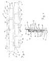
- FIG. 4is a cross sectional view through line 2 - 2 of FIG. 2 .
- a veneer wall panel 10preferably comprises a facing plate 18 , including a base plate 12 and a series of masonry or design elements 14 .
- the design elements 14project outwardly from the base plate 12 (see also FIG. 4 ).
- the base plate 12need not be a separate construction from the design elements 14 , but in a preferred embodiment (as illustrated) is provided in a separate plane.
- the design elements 14are simulated bricks aligned in a regimented pattern in accordance with standard masonry practices.
- the base plate between the design elementspreferably forms a mortar bed area 16 . As illustrated in FIG.
- the base plate 12 and design elements 14may be made from the same material, or may be made from different materials, or a combination of the two.
- the veneermay be a dry stack without a mortar bed per se. While illustrated as multiple design elements 14 and a flat panel 10 , one skilled in the art appreciates that while not illustrated or described in detail, the instant invention could comprise a single design element and/or any shape, such as a corner, a column (partial or complete), or any other useful shape.
- such a panelmay be grouted by positioning mortar between the design elements 14 so as to provide a finished masonry appearance.
- the panelis grouted at the jobsite by installing mortar after the panel is installed, as described in commonly assigned U.S. patent application Ser. No. 11/647,679 to Attebery, entitled “Fiber Reinforced Concrete Stone Panel System” filed concurrently herewith, which is incorporated herein by reference in its entirety (“Attebery”).
- the design elements 14 illustrated in the drawing figurecorrespond to simulated bricks, it should be appreciated that substantially any other masonry material known in the art may be simulated including bricks of different sizes, stones of different shapes and sizes, tiles of different shapes and sizes and the like.
- the base plate 12is preferably made from a cast or molded material such as concrete, reinforced concrete, gypsum, reinforced cementitious material, polymeric material (reinforced or unreinforced), metal and mixtures thereof.
- the cast materialincludes reinforcements comprising fibers selected from a group of materials consisting of glass fibers, mineral fibers, natural fibers, polymer fibers and mixtures thereof as described above. Where glass fibers are used, they are typically of the E-glass or AR-glass type which exhibits some alkali resistance.
- the cast veneer wall panel 10also comprises a backing panel generally designated by reference numeral 20 .
- the backing panelis best illustrated in FIGS. 2 through 4 .
- the backing panel 20especially where provided separate from the design elements 14 , preferably includes a series of concavities 22 that nest within the design elements 14 of the facing panel 18 . At least one aperture 24 is provided in each of the concavities 22 .
- the backing panel 20is preferably secured to the facing panel 18 by the cast material used to make the facing panel. More specifically, during production of a cast veneer wall panel some of the cast material preferably enters the concavities 22 through the apertures 24 (note set cast material 26 illustrated in FIG. 4 that keys the panels 18 , 20 together).
- That cast material 26laps around the margins of the backing panel 20 surrounding the apertures 24 .
- this cast materialsets the backing panel 20 is securely fastened to the facing panel 18 .
- the number of apertures 24may be one or several, depending on the process used and the characteristics desired.
- a single aperture 24is substantially as large as the concavity 22 is provided, with a small flange to engage the material 26 at the top and bottom of the aperture, or around the periphery thereof, similar to that illustrated in FIG. 4 .
- the backing panel 20includes a mounting flange 28 that projects beyond the upper edge of the facing panel 18 .
- the mounting flange 28may be optionally divided into identifiable zones by indentia such as the dashed line 30 .
- the portion 32 of the mounting flange 28 above the dashed line 30may be used by the installer to receive a nail or other fastener (not shown) to initially secure the cast veneer wall panel 10 to the underlying sheathing or studs of the building.
- the portion 34 below the dashed line 30may optionally be marked e.g. “no nail below line”. Alternatively the line 30 can be used to indicate a target where to nail the panel 10 .
- one or more dashed linesmay optionally be provided perpendicular to the illustrate line 30 as shown at 31 (illustrated at one mortar bed for example only), indicate lateral nail zones or “no nail” zones to avoid installation of fasteners where a fastener in an adjacent panel (below the top flange) may be installed, and may also serve as alignment features for the mortar bed area 16 of an adjacent panel.
- the lower flangewould likely be secured between the mortar bed 16 , as this would be free of fasteners in the panel installed below due to the markings 31 . This notice advises the installer not to use nails in the portion 34 or 31 thereby leaving this portion free and clear of any form of fastener.
- slotsmay be provided in the nail flange at 30 (similar to vinyl siding) as installation guides and/or to provide for installation in a manner more like siding without having to punch through material in the flange 28 .
- the backing panel 20preferably also includes a second flange 36 that extends along the bottom and one end of the panel 10 .
- the second flange 36corresponds to the width of the mortar bed area 16 .
- a series of registration marks 38are preferably provided on the backing panel 20 .
- one registration markis provided in the mounting flange 28 and four registration marks are provided along the second flange 36 .
- Each registration markis preferably aligned along the centerline of an adjacent design element 14 or in the mortar bed area 16 between adjacent design elements 14 , or may be provided at an edge of the design elements 14 .
- registration marksfunction to aid the installer in properly aligning the cast veneer wall panels 10 as they are secured to the side of the building to maintain the desired courseable pattern of a high quality masonry application, and may be used by an installer to cut the panel at predetermined lengths and/or positions indicated by the registration marks.
- one or more of the flanges 28 , 36may be provided as part of the design elements 14 and not as part of the backer 20 .
- the backeris provided at the top only and the remainder of the panel is concrete; or the backer may be provided at the top of the panel 10 and/or between courses of design elements 14 .
- the backing panel 20includes a front face 40 which engages the design elements 14 and a rear face 42 that is directed toward the sheathing S of the building upon installation of the wall panel 10 .
- a series of stiffening ribs 44project outwardly from the rear face 42 . These ribs preferably serve to stiffen the backing panel 20 and therefore the wall panel 10 but also function upon installation to provide an offset from the sheathing S thereby providing an air gap between the rear face 42 of the backing panel 20 and the sheathing S.
- the stiffening ribs 44are oriented so as to be axially aligned in a horizontal plane following installation of the wall panels 10 on the sheathing S. Breaks 45 may be provided periodically on the ribs 44 to allow drainage (and air circulation behind the panel) and prevent any accumulation of moisture on the ribs.
- the upper surface of the ribs 44may slope slightly toward the breaks 45 to assist drainage. Accordingly, any moisture permeating the wall panel 10 may be drawn by gravity through the breaks 45 to an underlying weep screed (not shown) for dissipating that moisture from the building or evaporate upon air circulation.
- the rear face 40 of the backing panel 20is provided with a series of spaced dimples 46 .
- the dimples 46project outwardly from the rear face 42 in the same manner as the stiffening ribs 44 in order to provide an appropriate air gap between the panel 10 and the sheathing S for moisture dissipation.
- the stiffening ribs 44 or the dimples 46may be cut down or ground down as necessary in order to compensate for any bowing or deviation in the sheathing S that might otherwise cause the wall panels 10 to seat improperly.
- the wall panel 10could also incorporate a combination of stiffening ribs 44 and dimples 46 if desired, or the ribs and/or dimples may be arranged in any orientation to achieve the desired properties.
- the backer 20may include a number of holes or slots to reduce the amount of material used in the backer 20 .
- FIG. 4illustrating the installation of one cast veneer wall panel 10 (illustrated in full line) over another cast veneer wall panel 10 ′ previously installed to the sheathing S of a building (the previously installed panel illustrated below in phantom line).
- the sheathing Smay be any known sheathing such as OSB, plywood, cement board, weatherproof gypsum, foam panels, etc. While not illustrated, one skilled in the art appreciates that a vapor barrier and/or weep screed may be installed over the sheathing S.
- the installerfirst installs a starter strip at the lowest point of the wall desired to be covered, so as to provide a straight line across the surface at the bottom of the wall in a manner known to one skilled in the art.
- the starter stripmay comprise a trim board, a flange similar to a siding starter strip, or a trim piece to resemble a course of brick or stone.
- the installermay forego the starter strip and may optionally install a piece of trim after the veneer is installed below the lowest course of the veneer along the bottom to finish the job.
- the first course of panel 10 ′is installed at the bottom of the wall.
- the installerthen installs a second course of panel 10 by positioning the panel 10 to the top of the design elements 14 ′ of the first course of panel 10 ′ and aligning one of the registration marks 38 in the second flange 36 at the bottom of the wall panel 10 with the registration line 38 in the mounting flange 36 of the wall panel already installed, or may align one or more registration marks 38 with the mortar bed area 16 ′ between design elements 14 ′ (ref. FIG. 1 ) in the previously installed panel 10 ′. This ensures that the design elements 14 and mortar bed area 16 between the design elements provided on the wall panels 10 are properly aligned to maintain the desired regimented pattern.
- the bottom edge of the wall panel 10 being installedpreferably rests against the top of the design elements 14 ′ at the top of the previously installed wall panel 10 ′. Since the second flange 36 at the bottom of the panel 10 is of a width corresponding to the mortar bed area 16 at the top of the lower panel 10 ′, the desired horizontal mortar bed height is maintained between rows of the design elements 14 of the two panels 10 . In a similar manner, proper spacing between the design elements 14 of side-by-side wall panels 10 is also maintained by the second margin 36 as illustrated at the left side 11 of the panel 10 in FIG. 1 , so as to maintain a proper vertical mortar bed 16 width between design elements 14 in adjacent panels (not shown).
- FIG. 1illustrates the flange 36 at the left end 11 of the panel, one skilled in the art appreciates that a flange could alternatively be provided at the right end 13 of the panel, or an overlapping flange may be provided (one on each end) in a manner similar to the top and bottom flanges 36 , 28 ′ as shown in FIG. 4 .
- FIGS. 2 and 3While the backer 20 is illustrated in FIGS. 2 and 3 as being substantially planar, the section of FIG. 4 illustrates the upper flange 28 as being substantially coplanar with the sheathing in FIG. 4 .
- the upper flange 28may also include dimples, ribs, depressions or the like so as to maintain an air gap for drainage and/or air passage (as indicated in FIGS. 2 and 3 ). This is illustrated in this manner in FIG. 4 , to show an embodiment where the top and bottom flanges 28 , 36 are designed so that the top flange 28 is in a plane below the plane of the bottom flange 36 so the overlap produces a constant thickness for the veneer installed on the wall.
- the bottom flange 36may be in a higher plane than the lower flange 28 (not illustrated).
- the flange at the left end 11 of the panel 10is either in a plane below the right end 13 , or the right end may include a recess that would nest over the flange 36 at the left end 11 to maintain the panel 10 generally in a flat planar relationship against the sheathing S.
- the flange 28includes depressions (not shown) where the panel is to be secured to the wall so as to provide for a flat mounting surface (and in this embodiment, the bottom flange is raised as described above to maintain the thickness of the panel after installation).
- the wall panel 10 being installedis maintained in this desired position preferably by then driving one or more nails, screws, staples or the like through the portion 32 of the mounting flange 28 above the dashed line 30 into the underlying sheathing S.
- an adhesive or tapemay be used to hold the panel in place. Additional screws or other fasteners may then be utilized to more securely fasten the wall panel 10 in position, preferably through the bottom flange 36 , or in the mortar joint 16 , and/or the top flange 28 .
- the panel 10could be secured through the design elements 14 in a less preferred installation.
- some screwsmay be driven through the second flange 36 at the bottom of the wall panel 10 at the point illustrated by action arrow A to tie the panels together, as well as secure both to the wall. These screws will pass freely through the second flange 36 of the upper wall panel 10 and the “no nail” portion of the mounting flange 28 of the lower panel 10 to secure both panels together, as well as to the sheathing S.
- the panels 10may be installed with or without fasteners using an adhesive or mortar as known to one skilled in the art.
- bracketsto hold the panels to the sheathing as known to one skilled in the art.
- the entire mortar bed area 16is grouted after the panels 10 are installed, as described in the Attebery application. In another embodiment, the mortar bed area 16 is finished prior to installation and the joints between panels may be filed grouted after installation, if necessary.
- the backing panel 20 used in the wall panel 10includes a main section including the concavities 22 and apertures 24 .
- the bodyalso includes the mounting flange 28 and the second flange 36 as well as stiffening ribs 44 and/or dimples 46 .
- the backing panel 20may be made from wood, treated wood, metal, such as steel, galvanized steel, aluminum or copper, or as a molded piece from a polymer or composite material, preferably as a single unitary molded piece.
- Polymer materials useful for the making of the backing panel 20include various thermoplastic and thermoset resins, including but not limited to polyolefins, polyesters, polyvinyl chloride, polypropylene, polyethylene, polyamide, epoxy, vinyl ester, and mixtures thereof.
- Composite materials used to make the backing panel 20include reinforcing material and a matrix binder.
- Appropriate reinforcing materials useful in the present inventioninclude but are not limited to glass fibers, natural fibers, mineral fibers, basalt fibers, carbon fibers, kenaf fibers, jute fibers, hemp fibers, E-glass fibers, C-glass fibers, R-glass fibers, S-glass fibers, ECR-glass fibers, AR-glass fibers, polymer fibers, carbon fibers, metal fibers, other known reinforcement fibers and mixtures thereof. It should be appreciated that substantially any type of glass fiber may be used for reinforcement fibers.
- Glass fibers appropriate for use in the present inventionmay be loose chopped strand or glass mat and include those available under the trademarks Hypertex and Advantex from the assignee of the invention.
- Matrix binder materials useful for this purposeinclude but are not limited to polyolefins, polyesters, polyvinyl chloride, polypropylene, polyethylene, polyamide and mixtures thereof.
- the backermay be made from any known operation for the materials, for example stamping for metal, injection molding or thermoforming for thermoplastics, spray-up, compression molding or other known technique for thermosets, or may comprise a molded reinforced concrete panel.
- the cast veneer wall panel 10may be easily made by adding, pouring or spraying uncured cast material 26 such as reinforced concrete into a product mold.
- uncured cast material 26such as reinforced concrete into a product mold.
- the preformed backing panel 20is positioned onto the cast material 26 , preferably prior to the setting of the cast material 26 .
- the backing panel 20is pressed into the cast material 26 sufficiently to force some cast material 26 through the keying apertures 24 provided in the concavities 22 in the backing panel 20 . Accordingly, the concavities 22 become partially filled with cast material 26 which laps over the margins of the backing panel 20 around the apertures 24 .
- the cast material 26 passing through the apertures 24is fully maintained within the concavities 22 so as not to interfere with the proper seating of the panel 10 on the sheathing S when installed.
- the methodincludes removing the cast veneer wall panel 10 from the mold.
- the backer 20may include projections from the front face 40 to engage the cast material 26 .
- the cast material 26may be adhered to the front face 40 during hardening or after the material is hardened.
- the backer 20is molded onto the cast material 26 .
Landscapes
- Engineering & Computer Science (AREA)
- Architecture (AREA)
- Chemical & Material Sciences (AREA)
- Ceramic Engineering (AREA)
- Civil Engineering (AREA)
- Structural Engineering (AREA)
- Manufacturing & Machinery (AREA)
- Mechanical Engineering (AREA)
- Finishing Walls (AREA)
Abstract
Description
Claims (19)
Priority Applications (3)
| Application Number | Priority Date | Filing Date | Title |
|---|---|---|---|
| US11/647,751US7997039B2 (en) | 2006-12-29 | 2006-12-29 | Veneer panel |
| PCT/US2007/025532WO2008082473A1 (en) | 2006-12-29 | 2007-12-13 | Veneer panel |
| US11/933,216US8042309B2 (en) | 2006-12-29 | 2008-01-25 | Panelized veneer with backer-to-backer locators |
Applications Claiming Priority (1)
| Application Number | Priority Date | Filing Date | Title |
|---|---|---|---|
| US11/647,751US7997039B2 (en) | 2006-12-29 | 2006-12-29 | Veneer panel |
Related Child Applications (2)
| Application Number | Title | Priority Date | Filing Date |
|---|---|---|---|
| US93321607AContinuation-In-Part | 2007-10-31 | 2007-10-31 | |
| US11/933,216Continuation-In-PartUS8042309B2 (en) | 2006-12-29 | 2008-01-25 | Panelized veneer with backer-to-backer locators |
Publications (2)
| Publication Number | Publication Date |
|---|---|
| US20080155921A1 US20080155921A1 (en) | 2008-07-03 |
| US7997039B2true US7997039B2 (en) | 2011-08-16 |
Family
ID=39267843
Family Applications (1)
| Application Number | Title | Priority Date | Filing Date |
|---|---|---|---|
| US11/647,751Active2030-03-29US7997039B2 (en) | 2006-12-29 | 2006-12-29 | Veneer panel |
Country Status (2)
| Country | Link |
|---|---|
| US (1) | US7997039B2 (en) |
| WO (1) | WO2008082473A1 (en) |
Cited By (17)
| Publication number | Priority date | Publication date | Assignee | Title |
|---|---|---|---|---|
| US20100107537A1 (en)* | 2008-10-30 | 2010-05-06 | Stephan Hauser | Method for Attaching a Reinforcement or Facing on an Existing Structural Component and Structural Component with Attached Reinforcement or Facing |
| US20110088337A1 (en)* | 2009-03-23 | 2011-04-21 | John Tancredi | Support panel for masonry |
| US20120159892A1 (en)* | 2010-12-23 | 2012-06-28 | Sashco, Inc. | System and method of securing roofing components with one another |
| USD663044S1 (en) | 2011-03-03 | 2012-07-03 | John Tancredi | Support panel |
| US20130199119A1 (en)* | 2012-02-07 | 2013-08-08 | Concrete Log Systems, Inc. | Board and Batten Siding System |
| USD697394S1 (en) | 2012-12-17 | 2014-01-14 | Quality Stone Veneer, Inc. | Clip |
| USD712569S1 (en) | 2012-12-18 | 2014-09-02 | Quality Stone Veneer, Inc. | Wall panel |
| US8935896B2 (en) | 2009-03-23 | 2015-01-20 | Glen-Gery Corporation | Masonry support panel and associated methods of use |
| US9016020B1 (en) | 2014-04-15 | 2015-04-28 | Jisong Yang | Thin brick panel assembly system |
| US9695596B2 (en) | 2011-05-02 | 2017-07-04 | Pacific Prebenched Ltd. | Natural rock panel, natural rock veneer panel and panel support apparatus |
| US9903124B2 (en) | 2008-02-06 | 2018-02-27 | Boral Stone Products Llc | Prefabricated wall panel with tongue and groove construction |
| USD857922S1 (en) | 2013-10-22 | 2019-08-27 | Certainteed Corporation | Manufactured siding panel with frame |
| USRE47694E1 (en) | 2012-08-08 | 2019-11-05 | Boral Stone Products Llc | Wall panel |
| US10682787B2 (en) | 2012-10-24 | 2020-06-16 | Certainteed Corporation | Method and apparatus for fabricating a building panel |
| US10844608B2 (en) | 2015-09-11 | 2020-11-24 | Oldcastle Building Products Canada Inc. | Cladding system |
| US10895077B2 (en) | 2018-03-30 | 2021-01-19 | Certainteed Llc | Frame for a wall panel, wall panel, and method of manufacture |
| US11332943B2 (en) | 2019-10-08 | 2022-05-17 | D.A. Distribution Inc. | Wall covering with adjustable spacing |
Families Citing this family (18)
| Publication number | Priority date | Publication date | Assignee | Title |
|---|---|---|---|---|
| AR038680A1 (en) | 2002-02-19 | 2005-01-26 | Synthes Ag | INTERVERTEBRAL IMPLANT |
| CA2515247C (en) | 2003-02-06 | 2010-10-05 | Synthes (U.S.A.) | Intervertebral implant |
| EP1988855A2 (en) | 2006-02-27 | 2008-11-12 | Synthes GmbH | Intervertebral implant with fixation geometry |
| US8042309B2 (en)* | 2006-12-29 | 2011-10-25 | Boral Stone Products Llc | Panelized veneer with backer-to-backer locators |
| JP2011502708A (en) | 2007-11-16 | 2011-01-27 | ジンテス ゲゼルシャフト ミット ベシュレンクテル ハフツング | Low profile intervertebral implant |
| CN102256570B (en) | 2008-11-07 | 2015-09-02 | 斯恩蒂斯有限公司 | Spacer and connecting plate assembly between vertebral bodies |
| WO2012088238A2 (en) | 2010-12-21 | 2012-06-28 | Synthes Usa, Llc | Intervertebral implants, systems, and methods of use |
| US9241809B2 (en) | 2010-12-21 | 2016-01-26 | DePuy Synthes Products, Inc. | Intervertebral implants, systems, and methods of use |
| US9677283B2 (en)* | 2011-03-16 | 2017-06-13 | Talus Systems, LLC | Building veneer system |
| US9587398B1 (en) | 2011-03-16 | 2017-03-07 | Talus Systems, LLC | Building veneer system |
| GB201116452D0 (en)* | 2011-09-23 | 2011-11-02 | T T S Shipping Ltd | Door, monitoring system and method |
| US20140134392A1 (en)* | 2012-11-12 | 2014-05-15 | ForzaStone LLC | Composite stone panels |
| BR202015021468U2 (en)* | 2014-09-08 | 2016-03-15 | Gustavo Antonio Muller | polymer-based Venetian mosaics |
| US9867718B2 (en) | 2014-10-22 | 2018-01-16 | DePuy Synthes Products, Inc. | Intervertebral implants, systems, and methods of use |
| US9464442B1 (en)* | 2015-08-13 | 2016-10-11 | Stone Master Sa | Wall cladding assembly method and system |
| US10738475B2 (en)* | 2015-10-30 | 2020-08-11 | Boral Ip Holdings (Australia) Pty Limited | Wall panel with rain screen |
| CN112302203A (en)* | 2020-11-10 | 2021-02-02 | 上海品宅装饰科技有限公司 | Bamboo-wood fiber board and mounting method thereof |
| GB2624398A (en)* | 2022-11-16 | 2024-05-22 | Persimmon Homes Ltd | Construction component and method of manufacture |
Citations (68)
| Publication number | Priority date | Publication date | Assignee | Title |
|---|---|---|---|---|
| US1592591A (en)* | 1925-05-29 | 1926-07-13 | Amele James | Apparatus for and method of making stucco-brick slabs |
| US1853822A (en)* | 1931-01-22 | 1932-04-12 | New Brick Corp | Wall covering |
| US1853824A (en)* | 1931-03-09 | 1932-04-12 | New Brick Corp | Wall covering |
| US1976947A (en) | 1932-08-24 | 1934-10-16 | Eva Krauss | Wall veneer |
| US2006635A (en)* | 1934-06-29 | 1935-07-02 | Joseph W Farr | Covering or facing element for buildings |
| US2031680A (en)* | 1932-06-11 | 1936-02-25 | Tuthill Jay Lloyd | Wall covering |
| GB444503A (en) | 1934-11-16 | 1936-03-23 | Trussed Concrete Steel Co | Improvements in the construction of floor tiles and facing slabs |
| US2198466A (en)* | 1938-06-29 | 1940-04-23 | Albert E Stolze | Siding for buildings |
| US2209283A (en)* | 1939-11-02 | 1940-07-23 | Peter A Parker | Building unit |
| US2329610A (en)* | 1940-10-02 | 1943-09-14 | Eugene S Harman | Building panel |
| US3177279A (en) | 1961-10-19 | 1965-04-06 | Cavrok Mfg Company | Method of molding a decorative building panel |
| US3248834A (en)* | 1963-10-29 | 1966-05-03 | Polis Charles | Simulated brick interior siding assembly |
| US3332187A (en) | 1963-12-11 | 1967-07-25 | Brix Corp | Brick wall panel and method of making |
| US3344011A (en)* | 1964-11-02 | 1967-09-26 | Goozner Murray | Terrazzo tile |
| US3350827A (en) | 1964-01-02 | 1967-11-07 | Ridge Rock Ind Inc | Building panels and method of mounting the panels |
| US3524790A (en) | 1967-01-03 | 1970-08-18 | Nat Distillers Chem Corp | Simulated masonry facing panel |
| US3533206A (en)* | 1968-07-16 | 1970-10-13 | James K Passeno Jr | Building block holder for fabricating veneer walls |
| US3613326A (en) | 1969-10-03 | 1971-10-19 | Alside Int Corp | Preformed simulated brick panel having stepped edges |
| US3621625A (en)* | 1970-08-17 | 1971-11-23 | Robert S Medow | Brick siding |
| US3646715A (en) | 1970-04-06 | 1972-03-07 | Du Pont Canada | Prefabricated building panel |
| US3701228A (en) | 1970-07-23 | 1972-10-31 | Frank Taylor | Decorative wall facing |
| US3740910A (en) | 1971-11-01 | 1973-06-26 | Merry Co Inc | Simulated brick panels |
| US3908326A (en) | 1973-12-20 | 1975-09-30 | Gerald T Francis | Brick panel construction |
| US3968610A (en) | 1974-12-09 | 1976-07-13 | Medow Robert S | Facing structures for building |
| US4026083A (en) | 1976-04-29 | 1977-05-31 | Betco Block & Products, Inc. | Brickwork form |
| US4219984A (en) | 1978-11-30 | 1980-09-02 | San Maurice G De | Method of manufacturing building panels |
| US4271111A (en) | 1978-11-13 | 1981-06-02 | Sheber Thomas F | Embossed concrete building panels and method |
| US4299069A (en) | 1977-11-28 | 1981-11-10 | Alfred Neumann | Prefabricated wall facing panels |
| US4407104A (en) | 1980-10-02 | 1983-10-04 | Francis Gerald T | Brick panel insulation with load bearing clip |
| US4468903A (en)* | 1982-05-03 | 1984-09-04 | Masonite Corporation | Building panel |
| US4495738A (en) | 1978-11-13 | 1985-01-29 | Sheber Thomas F | Embossed concrete building panels |
| US4644719A (en) | 1983-06-10 | 1987-02-24 | Salazar Edward J | Decorative wall panel |
| US4665673A (en) | 1984-04-26 | 1987-05-19 | Silvio Diana | Monolithic surface ornamentation of pre-cast reinforced concrete wall |
| US4773201A (en)* | 1987-04-21 | 1988-09-27 | Ronald Trezza | Method and structure for attaching brick facing or the like to a supporting structure |
| US4858410A (en)* | 1989-03-17 | 1989-08-22 | Goldman Robert I | Modular brickwork form |
| US4932182A (en)* | 1989-11-09 | 1990-06-12 | Thomasson John R | Floor tile forming and structural underlayment device |
| US5052161A (en) | 1989-11-08 | 1991-10-01 | Whitacre Daniel C | Tile application structure |
| US5228937A (en) | 1991-04-03 | 1993-07-20 | National Brick Panel Systems, Inc. | Method of making a brick panel |
| US5232646A (en) | 1990-11-07 | 1993-08-03 | Concrete Design Specialties, Inc. | Methods of forming contoured walls |
| US5540023A (en)* | 1995-06-07 | 1996-07-30 | Jaenson Wire Company | Lathing |
| US5787666A (en) | 1994-12-23 | 1998-08-04 | Sherry; Edward B. | Thin masonry veneer panel system and the fabrication thereof |
| US5916103A (en)* | 1997-12-17 | 1999-06-29 | Roberts; Jimmie A. | Interconnected roofing shingles |
| US6151854A (en) | 1997-07-24 | 2000-11-28 | Gutjahr; Walter | Profiled web for venting and draining floor tiles, particularly ceramic tiles, laid in a thin retaining layer |
| US6237288B1 (en)* | 1990-10-23 | 2001-05-29 | Certainteed Corporation | Roofing shingle bearing release material with identifying indicia |
| US6355193B1 (en) | 2000-03-01 | 2002-03-12 | Gale Stott | Method for making a faux stone concrete panel |
| US6408585B1 (en) | 1999-04-19 | 2002-06-25 | Hiroshi Tajima | Attachment structure for undefined or random-shaped wall facing material |
| US6516578B1 (en) | 2001-02-12 | 2003-02-11 | Garrick W. Hunsaker | Thin brick panel system |
| US20030066259A1 (en) | 2001-09-10 | 2003-04-10 | Sudweeks Dan L. | Fastener system and method for attaching manufactured brick or stone to a surface |
| US20040107663A1 (en)* | 2002-12-04 | 2004-06-10 | Kurt Waggoner | Siding having indicia defining a fastening zone and methods for manufacturing and installing siding having indicia defining a fastening zone |
| USD497013S1 (en) | 2003-09-22 | 2004-10-05 | Monarch Manufacturing Company | Panel for a window well area wall |
| US6802165B1 (en) | 1999-03-26 | 2004-10-12 | J. Kenneth Passeno | Thin brick panel construction |
| US6830405B2 (en) | 2000-05-29 | 2004-12-14 | Nichiha Corporation | Fastening member |
| US6857248B2 (en) | 2001-05-24 | 2005-02-22 | Les Materiaux De'construction Oldcastle Canada Inc. | Panel, a kit and a method for forming a masonry wall |
| US20050188642A1 (en) | 2004-02-13 | 2005-09-01 | Rinox Inc. | Decorative brick facade module for walls |
| USD510146S1 (en) | 2004-02-17 | 2005-09-27 | Attebery Ii Harold C | Masonry tile |
| US20050210811A1 (en) | 2004-02-17 | 2005-09-29 | Nasvik Paul C | Precast concrete veneer panel system |
| US6951086B2 (en) | 2002-05-20 | 2005-10-04 | James Kenneth Passeno | Method and apparatus for making thin brick wall facing |
| US20050257475A1 (en) | 2004-05-21 | 2005-11-24 | Ruigang Gong | Thin brick veneer panel |
| US6973756B2 (en) | 2003-05-07 | 2005-12-13 | Michael Hatzinikolas | Connector and system for supporting veneer panels |
| US6990778B2 (en) | 2002-09-18 | 2006-01-31 | Passeno James K | Brick veneer assembly |
| WO2006042883A2 (en) | 2004-08-20 | 2006-04-27 | Azulindus Y Marti, S.A. | Removable surface covering |
| USRE39091E1 (en) | 1996-02-15 | 2006-05-09 | Stonetile (Canada) Ltd. | Concrete panel construction |
| US20070022687A1 (en) | 2005-07-28 | 2007-02-01 | Horacio Correia | Decorative stone module |
| US20070137128A1 (en) | 2005-12-02 | 2007-06-21 | Nicolas Viau | Modular stone panel |
| US20090049765A1 (en)* | 2007-06-22 | 2009-02-26 | Matthew Bruce Grant | Membrane for use in the construction of buildings |
| US20090193742A1 (en)* | 2008-02-06 | 2009-08-06 | Wolf David H | Prefabricated wall panel with tongue and groove construction |
| US20090249719A1 (en)* | 2008-04-04 | 2009-10-08 | Joshua Michael Broehl | Cheater panel |
| US7617647B2 (en)* | 2004-10-26 | 2009-11-17 | Tilediy, Llc | Underlayment for tile surface |
Family Cites Families (8)
| Publication number | Priority date | Publication date | Assignee | Title |
|---|---|---|---|---|
| US448733A (en)* | 1891-03-24 | Metallic facing-plate | ||
| US4034528A (en)* | 1976-06-18 | 1977-07-12 | Aegean Industries, Inc. | Insulating vinyl siding |
| US5355193A (en)* | 1993-10-20 | 1994-10-11 | Eastman Kodak Company | Film code reader assembly for a film scanner |
| US5387666A (en)* | 1994-06-20 | 1995-02-07 | General Electric Company | Branched polyesters prepared from macrocyclic poly(Alkylene Dicarboxylate) oligomers |
| US5956914A (en)* | 1998-05-05 | 1999-09-28 | Williamson; David L. | Vinyl siding panels for building exteriors |
| US6336303B1 (en)* | 1999-05-07 | 2002-01-08 | Atlantis Plastics, Inc. | Injection molded exterior siding panel with positioning relief and method of installation |
| US7207145B2 (en)* | 2003-10-30 | 2007-04-24 | Certainteed Corporation | Siding panel tab and slot joint |
| US7735287B2 (en)* | 2006-10-04 | 2010-06-15 | Novik, Inc. | Roofing panels and roofing system employing the same |
- 2006
- 2006-12-29USUS11/647,751patent/US7997039B2/enactiveActive
- 2007
- 2007-12-13WOPCT/US2007/025532patent/WO2008082473A1/enactiveApplication Filing
Patent Citations (71)
| Publication number | Priority date | Publication date | Assignee | Title |
|---|---|---|---|---|
| US1592591A (en)* | 1925-05-29 | 1926-07-13 | Amele James | Apparatus for and method of making stucco-brick slabs |
| US1853822A (en)* | 1931-01-22 | 1932-04-12 | New Brick Corp | Wall covering |
| US1853824A (en)* | 1931-03-09 | 1932-04-12 | New Brick Corp | Wall covering |
| US2031680A (en)* | 1932-06-11 | 1936-02-25 | Tuthill Jay Lloyd | Wall covering |
| US1976947A (en) | 1932-08-24 | 1934-10-16 | Eva Krauss | Wall veneer |
| US2006635A (en)* | 1934-06-29 | 1935-07-02 | Joseph W Farr | Covering or facing element for buildings |
| GB444503A (en) | 1934-11-16 | 1936-03-23 | Trussed Concrete Steel Co | Improvements in the construction of floor tiles and facing slabs |
| US2198466A (en)* | 1938-06-29 | 1940-04-23 | Albert E Stolze | Siding for buildings |
| US2209283A (en)* | 1939-11-02 | 1940-07-23 | Peter A Parker | Building unit |
| US2329610A (en)* | 1940-10-02 | 1943-09-14 | Eugene S Harman | Building panel |
| US3177279A (en) | 1961-10-19 | 1965-04-06 | Cavrok Mfg Company | Method of molding a decorative building panel |
| US3248834A (en)* | 1963-10-29 | 1966-05-03 | Polis Charles | Simulated brick interior siding assembly |
| US3332187A (en) | 1963-12-11 | 1967-07-25 | Brix Corp | Brick wall panel and method of making |
| US3350827A (en) | 1964-01-02 | 1967-11-07 | Ridge Rock Ind Inc | Building panels and method of mounting the panels |
| US3344011A (en)* | 1964-11-02 | 1967-09-26 | Goozner Murray | Terrazzo tile |
| US3524790A (en) | 1967-01-03 | 1970-08-18 | Nat Distillers Chem Corp | Simulated masonry facing panel |
| US3533206A (en)* | 1968-07-16 | 1970-10-13 | James K Passeno Jr | Building block holder for fabricating veneer walls |
| US3613326A (en) | 1969-10-03 | 1971-10-19 | Alside Int Corp | Preformed simulated brick panel having stepped edges |
| US3646715A (en) | 1970-04-06 | 1972-03-07 | Du Pont Canada | Prefabricated building panel |
| US3701228A (en) | 1970-07-23 | 1972-10-31 | Frank Taylor | Decorative wall facing |
| US3621625A (en)* | 1970-08-17 | 1971-11-23 | Robert S Medow | Brick siding |
| US3740910A (en) | 1971-11-01 | 1973-06-26 | Merry Co Inc | Simulated brick panels |
| US3908326A (en) | 1973-12-20 | 1975-09-30 | Gerald T Francis | Brick panel construction |
| US3968610A (en) | 1974-12-09 | 1976-07-13 | Medow Robert S | Facing structures for building |
| US4026083A (en) | 1976-04-29 | 1977-05-31 | Betco Block & Products, Inc. | Brickwork form |
| US4299069A (en) | 1977-11-28 | 1981-11-10 | Alfred Neumann | Prefabricated wall facing panels |
| US4271111A (en) | 1978-11-13 | 1981-06-02 | Sheber Thomas F | Embossed concrete building panels and method |
| US4495738A (en) | 1978-11-13 | 1985-01-29 | Sheber Thomas F | Embossed concrete building panels |
| US4219984A (en) | 1978-11-30 | 1980-09-02 | San Maurice G De | Method of manufacturing building panels |
| US4407104A (en) | 1980-10-02 | 1983-10-04 | Francis Gerald T | Brick panel insulation with load bearing clip |
| US4468903A (en)* | 1982-05-03 | 1984-09-04 | Masonite Corporation | Building panel |
| US4644719A (en) | 1983-06-10 | 1987-02-24 | Salazar Edward J | Decorative wall panel |
| US4665673A (en) | 1984-04-26 | 1987-05-19 | Silvio Diana | Monolithic surface ornamentation of pre-cast reinforced concrete wall |
| US4773201A (en)* | 1987-04-21 | 1988-09-27 | Ronald Trezza | Method and structure for attaching brick facing or the like to a supporting structure |
| US4858410A (en)* | 1989-03-17 | 1989-08-22 | Goldman Robert I | Modular brickwork form |
| US5052161A (en) | 1989-11-08 | 1991-10-01 | Whitacre Daniel C | Tile application structure |
| US4932182A (en)* | 1989-11-09 | 1990-06-12 | Thomasson John R | Floor tile forming and structural underlayment device |
| US6237288B1 (en)* | 1990-10-23 | 2001-05-29 | Certainteed Corporation | Roofing shingle bearing release material with identifying indicia |
| US5232646B1 (en) | 1990-11-07 | 1999-02-16 | Concrete Design Specialties In | Methods of forming contoured walls |
| US5232646A (en) | 1990-11-07 | 1993-08-03 | Concrete Design Specialties, Inc. | Methods of forming contoured walls |
| US5228937A (en) | 1991-04-03 | 1993-07-20 | National Brick Panel Systems, Inc. | Method of making a brick panel |
| US5311714A (en) | 1991-04-03 | 1994-05-17 | National Brick Panel Systems, Inc. | Brick panel apparatus |
| US5787666A (en) | 1994-12-23 | 1998-08-04 | Sherry; Edward B. | Thin masonry veneer panel system and the fabrication thereof |
| US5540023B1 (en)* | 1995-06-07 | 2000-10-17 | Jaenson Wire Company | Lathing |
| US5540023A (en)* | 1995-06-07 | 1996-07-30 | Jaenson Wire Company | Lathing |
| USRE39091E1 (en) | 1996-02-15 | 2006-05-09 | Stonetile (Canada) Ltd. | Concrete panel construction |
| US6151854A (en) | 1997-07-24 | 2000-11-28 | Gutjahr; Walter | Profiled web for venting and draining floor tiles, particularly ceramic tiles, laid in a thin retaining layer |
| US5916103A (en)* | 1997-12-17 | 1999-06-29 | Roberts; Jimmie A. | Interconnected roofing shingles |
| US6802165B1 (en) | 1999-03-26 | 2004-10-12 | J. Kenneth Passeno | Thin brick panel construction |
| US6408585B1 (en) | 1999-04-19 | 2002-06-25 | Hiroshi Tajima | Attachment structure for undefined or random-shaped wall facing material |
| US6355193B1 (en) | 2000-03-01 | 2002-03-12 | Gale Stott | Method for making a faux stone concrete panel |
| US6830405B2 (en) | 2000-05-29 | 2004-12-14 | Nichiha Corporation | Fastening member |
| US6516578B1 (en) | 2001-02-12 | 2003-02-11 | Garrick W. Hunsaker | Thin brick panel system |
| US6857248B2 (en) | 2001-05-24 | 2005-02-22 | Les Materiaux De'construction Oldcastle Canada Inc. | Panel, a kit and a method for forming a masonry wall |
| US20030066259A1 (en) | 2001-09-10 | 2003-04-10 | Sudweeks Dan L. | Fastener system and method for attaching manufactured brick or stone to a surface |
| US6951086B2 (en) | 2002-05-20 | 2005-10-04 | James Kenneth Passeno | Method and apparatus for making thin brick wall facing |
| US6990778B2 (en) | 2002-09-18 | 2006-01-31 | Passeno James K | Brick veneer assembly |
| US20040107663A1 (en)* | 2002-12-04 | 2004-06-10 | Kurt Waggoner | Siding having indicia defining a fastening zone and methods for manufacturing and installing siding having indicia defining a fastening zone |
| US6973756B2 (en) | 2003-05-07 | 2005-12-13 | Michael Hatzinikolas | Connector and system for supporting veneer panels |
| USD497013S1 (en) | 2003-09-22 | 2004-10-05 | Monarch Manufacturing Company | Panel for a window well area wall |
| US20050188642A1 (en) | 2004-02-13 | 2005-09-01 | Rinox Inc. | Decorative brick facade module for walls |
| US20050210811A1 (en) | 2004-02-17 | 2005-09-29 | Nasvik Paul C | Precast concrete veneer panel system |
| USD510146S1 (en) | 2004-02-17 | 2005-09-27 | Attebery Ii Harold C | Masonry tile |
| US20050257475A1 (en) | 2004-05-21 | 2005-11-24 | Ruigang Gong | Thin brick veneer panel |
| WO2006042883A2 (en) | 2004-08-20 | 2006-04-27 | Azulindus Y Marti, S.A. | Removable surface covering |
| US7617647B2 (en)* | 2004-10-26 | 2009-11-17 | Tilediy, Llc | Underlayment for tile surface |
| US20070022687A1 (en) | 2005-07-28 | 2007-02-01 | Horacio Correia | Decorative stone module |
| US20070137128A1 (en) | 2005-12-02 | 2007-06-21 | Nicolas Viau | Modular stone panel |
| US20090049765A1 (en)* | 2007-06-22 | 2009-02-26 | Matthew Bruce Grant | Membrane for use in the construction of buildings |
| US20090193742A1 (en)* | 2008-02-06 | 2009-08-06 | Wolf David H | Prefabricated wall panel with tongue and groove construction |
| US20090249719A1 (en)* | 2008-04-04 | 2009-10-08 | Joshua Michael Broehl | Cheater panel |
Non-Patent Citations (1)
| Title |
|---|
| International Search Report dated Apr. 21, 2008 in PCT/US2007/025532. |
Cited By (30)
| Publication number | Priority date | Publication date | Assignee | Title |
|---|---|---|---|---|
| US9903124B2 (en) | 2008-02-06 | 2018-02-27 | Boral Stone Products Llc | Prefabricated wall panel with tongue and groove construction |
| US10557273B2 (en) | 2008-02-06 | 2020-02-11 | Boral Stone Products Llc | Prefabricated wall panel with tongue and groove construction |
| US10378216B2 (en) | 2008-02-06 | 2019-08-13 | Boral Stone Products Llc | Prefabricated wall panel with tongue and groove construction |
| US10329775B2 (en) | 2008-02-06 | 2019-06-25 | Boral Ip Holdings (Australia) Pty Limited | Method of forming a wall panel |
| US11891814B2 (en) | 2008-02-06 | 2024-02-06 | Westlake Royal Stone Llc | Prefabricated wall panel with tongue and groove construction |
| US20100107537A1 (en)* | 2008-10-30 | 2010-05-06 | Stephan Hauser | Method for Attaching a Reinforcement or Facing on an Existing Structural Component and Structural Component with Attached Reinforcement or Facing |
| US8397457B2 (en)* | 2008-10-30 | 2013-03-19 | Stephan Hauser | Method for attaching a reinforcement or facing on an existing structural component and structural component with attached reinforcement or facing |
| US10041257B2 (en) | 2009-03-23 | 2018-08-07 | Glen-Gery Corporation | Masonry support panel and associated methods of use |
| US20110088337A1 (en)* | 2009-03-23 | 2011-04-21 | John Tancredi | Support panel for masonry |
| US8935896B2 (en) | 2009-03-23 | 2015-01-20 | Glen-Gery Corporation | Masonry support panel and associated methods of use |
| US8397470B2 (en)* | 2010-12-23 | 2013-03-19 | Sashco, Inc. | System and method of securing roofing components with one another |
| US20120159892A1 (en)* | 2010-12-23 | 2012-06-28 | Sashco, Inc. | System and method of securing roofing components with one another |
| USD663044S1 (en) | 2011-03-03 | 2012-07-03 | John Tancredi | Support panel |
| US9695596B2 (en) | 2011-05-02 | 2017-07-04 | Pacific Prebenched Ltd. | Natural rock panel, natural rock veneer panel and panel support apparatus |
| US20130199119A1 (en)* | 2012-02-07 | 2013-08-08 | Concrete Log Systems, Inc. | Board and Batten Siding System |
| USRE47694E1 (en) | 2012-08-08 | 2019-11-05 | Boral Stone Products Llc | Wall panel |
| US11828071B2 (en) | 2012-10-24 | 2023-11-28 | Certainteed Llc | Manufactured building panel assembly |
| US10682787B2 (en) | 2012-10-24 | 2020-06-16 | Certainteed Corporation | Method and apparatus for fabricating a building panel |
| US11047134B2 (en) | 2012-10-24 | 2021-06-29 | Certainteed Llc | Manufactured building panel |
| USD697394S1 (en) | 2012-12-17 | 2014-01-14 | Quality Stone Veneer, Inc. | Clip |
| USD712569S1 (en) | 2012-12-18 | 2014-09-02 | Quality Stone Veneer, Inc. | Wall panel |
| USD910207S1 (en) | 2013-10-22 | 2021-02-09 | Certainteed Corporation | Manufactured siding panel with frame |
| USD857922S1 (en) | 2013-10-22 | 2019-08-27 | Certainteed Corporation | Manufactured siding panel with frame |
| US9016020B1 (en) | 2014-04-15 | 2015-04-28 | Jisong Yang | Thin brick panel assembly system |
| US10844608B2 (en) | 2015-09-11 | 2020-11-24 | Oldcastle Building Products Canada Inc. | Cladding system |
| US10895077B2 (en) | 2018-03-30 | 2021-01-19 | Certainteed Llc | Frame for a wall panel, wall panel, and method of manufacture |
| US11530538B2 (en) | 2018-03-30 | 2022-12-20 | Certainteed Llc | Frame for a wall panel, wall panel, and method of manufacture |
| USD1044039S1 (en) | 2018-03-30 | 2024-09-24 | Certainteed Llc | Wall panel frame |
| US12203273B2 (en) | 2018-03-30 | 2025-01-21 | Certainteed Llc | Frame for a wall panel, wall panel, and method of manufacture |
| US11332943B2 (en) | 2019-10-08 | 2022-05-17 | D.A. Distribution Inc. | Wall covering with adjustable spacing |
Also Published As
| Publication number | Publication date |
|---|---|
| US20080155921A1 (en) | 2008-07-03 |
| WO2008082473A1 (en) | 2008-07-10 |
Similar Documents
| Publication | Publication Date | Title |
|---|---|---|
| US7997039B2 (en) | Veneer panel | |
| US8042309B2 (en) | Panelized veneer with backer-to-backer locators | |
| US11891814B2 (en) | Prefabricated wall panel with tongue and groove construction | |
| US7089709B2 (en) | Siding having indicia defining a fastening zone | |
| US8448401B2 (en) | Fiber cement board surface product | |
| US9556619B2 (en) | Fiber enforced thin brick sheet and process | |
| CA3080751C (en) | Panelized lath and drainage plane system for building exteriors | |
| US8136316B2 (en) | Roof and wall covering with improved corner construction | |
| US8359799B2 (en) | Building module, a method for making same, and a method for using same to construct a building | |
| US10753092B1 (en) | Fiber reinforced surface covering | |
| JP6635291B2 (en) | Transparent temporary frame structure of external insulation that forms a reinforced concrete building with no adjacent ground | |
| US20080155938A1 (en) | Fiber reinforced concrete stone panel system | |
| WO1997004198A1 (en) | Facing panel | |
| US20100251655A1 (en) | Universal mounting clip for siding strips installed in a horizontal overlapping pattern | |
| US20080196354A1 (en) | Fiber Reinforced Concrete Exterior Wall System | |
| US6802163B2 (en) | Plant-on building enhancement | |
| US20080196336A1 (en) | Fiber reinforced concrete exterior wall system | |
| KR20140008569A (en) | If the moisture bamrrier wall and concrete sub-floor room for suppan panel manufaeturing method. | |
| JP6710855B2 (en) | Adjacent ground-free transparent temporary frame structure for external insulation forming reinforced concrete buildings | |
| WO2009059000A1 (en) | Panelized veneer with backer-to-backer locators |
Legal Events
| Date | Code | Title | Description |
|---|---|---|---|
| AS | Assignment | Owner name:OWENS-CORNING FIBERGLAS TECHNOLOGY, INC., ILLINOIS Free format text:ASSIGNMENT OF ASSIGNORS INTEREST;ASSIGNORS:WOLF, DAVID H.;ATTEBERY II, HAROLD C.;KLOTZ, JEFF;AND OTHERS;REEL/FRAME:019130/0105;SIGNING DATES FROM 20070311 TO 20070403 Owner name:OWENS-CORNING FIBERGLAS TECHNOLOGY, INC., ILLINOIS Free format text:ASSIGNMENT OF ASSIGNORS INTEREST;ASSIGNORS:WOLF, DAVID H.;ATTEBERY II, HAROLD C.;KLOTZ, JEFF;AND OTHERS;SIGNING DATES FROM 20070311 TO 20070403;REEL/FRAME:019130/0105 | |
| AS | Assignment | Owner name:OWENS CORNING INTELLECTUAL CAPITAL, LLC, OHIO Free format text:ASSIGNMENT OF ASSIGNORS INTEREST;ASSIGNOR:OWENS-CORNING FIBERGLASS TECHNOLOGY, INC.;REEL/FRAME:019795/0433 Effective date:20070803 Owner name:OWENS CORNING INTELLECTUAL CAPITAL, LLC,OHIO Free format text:ASSIGNMENT OF ASSIGNORS INTEREST;ASSIGNOR:OWENS-CORNING FIBERGLASS TECHNOLOGY, INC.;REEL/FRAME:019795/0433 Effective date:20070803 Owner name:OWENS CORNING INTELLECTUAL CAPITAL, LLC, OHIO Free format text:ASSIGNMENT OF ASSIGNORS INTEREST;ASSIGNOR:OWENS-CORNING FIBERGLAS TECHNOLOGY, INC.;REEL/FRAME:019795/0433 Effective date:20070803 | |
| AS | Assignment | Owner name:BORAL STONE PRODUCTS LLC, GEORGIA Free format text:CHANGE OF NAME;ASSIGNOR:OWENS CORNING MASONRY PRODUCTS, LLC;REEL/FRAME:025644/0807 Effective date:20101231 Owner name:OWENS CORNING MASONRY PRODUCTS, LLC, GEORGIA Free format text:ASSIGNMENT OF ASSIGNORS INTEREST;ASSIGNOR:OWENS CORNING INTELLECTUAL CAPITAL, LLC;REEL/FRAME:025643/0820 Effective date:20101231 | |
| STCF | Information on status: patent grant | Free format text:PATENTED CASE | |
| FPAY | Fee payment | Year of fee payment:4 | |
| MAFP | Maintenance fee payment | Free format text:PAYMENT OF MAINTENANCE FEE, 8TH YEAR, LARGE ENTITY (ORIGINAL EVENT CODE: M1552); ENTITY STATUS OF PATENT OWNER: LARGE ENTITY Year of fee payment:8 | |
| MAFP | Maintenance fee payment | Free format text:PAYMENT OF MAINTENANCE FEE, 12TH YEAR, LARGE ENTITY (ORIGINAL EVENT CODE: M1553); ENTITY STATUS OF PATENT OWNER: LARGE ENTITY Year of fee payment:12 |