US7995796B2 - System for road sign sheeting classification - Google Patents
System for road sign sheeting classificationDownload PDFInfo
- Publication number
- US7995796B2 US7995796B2US12/419,843US41984309AUS7995796B2US 7995796 B2US7995796 B2US 7995796B2US 41984309 AUS41984309 AUS 41984309AUS 7995796 B2US7995796 B2US 7995796B2
- Authority
- US
- United States
- Prior art keywords
- retroreflectivity
- sheeting
- sign
- road sign
- vehicle
- Prior art date
- Legal status (The legal status is an assumption and is not a legal conclusion. Google has not performed a legal analysis and makes no representation as to the accuracy of the status listed.)
- Expired - Fee Related, expires
Links
Images


Classifications
- G—PHYSICS
- G08—SIGNALLING
- G08G—TRAFFIC CONTROL SYSTEMS
- G08G1/00—Traffic control systems for road vehicles
- G08G1/09—Arrangements for giving variable traffic instructions
- G08G1/0962—Arrangements for giving variable traffic instructions having an indicator mounted inside the vehicle, e.g. giving voice messages
- G08G1/0967—Systems involving transmission of highway information, e.g. weather, speed limits
- G08G1/096733—Systems involving transmission of highway information, e.g. weather, speed limits where a selection of the information might take place
- G08G1/096758—Systems involving transmission of highway information, e.g. weather, speed limits where a selection of the information might take place where no selection takes place on the transmitted or the received information
- G—PHYSICS
- G01—MEASURING; TESTING
- G01N—INVESTIGATING OR ANALYSING MATERIALS BY DETERMINING THEIR CHEMICAL OR PHYSICAL PROPERTIES
- G01N21/00—Investigating or analysing materials by the use of optical means, i.e. using sub-millimetre waves, infrared, visible or ultraviolet light
- G01N21/17—Systems in which incident light is modified in accordance with the properties of the material investigated
- G01N21/25—Colour; Spectral properties, i.e. comparison of effect of material on the light at two or more different wavelengths or wavelength bands
- G01N21/251—Colorimeters; Construction thereof
- G—PHYSICS
- G01—MEASURING; TESTING
- G01N—INVESTIGATING OR ANALYSING MATERIALS BY DETERMINING THEIR CHEMICAL OR PHYSICAL PROPERTIES
- G01N21/00—Investigating or analysing materials by the use of optical means, i.e. using sub-millimetre waves, infrared, visible or ultraviolet light
- G01N21/17—Systems in which incident light is modified in accordance with the properties of the material investigated
- G01N21/55—Specular reflectivity
- G—PHYSICS
- G01—MEASURING; TESTING
- G01N—INVESTIGATING OR ANALYSING MATERIALS BY DETERMINING THEIR CHEMICAL OR PHYSICAL PROPERTIES
- G01N21/00—Investigating or analysing materials by the use of optical means, i.e. using sub-millimetre waves, infrared, visible or ultraviolet light
- G01N21/84—Systems specially adapted for particular applications
- G—PHYSICS
- G01—MEASURING; TESTING
- G01S—RADIO DIRECTION-FINDING; RADIO NAVIGATION; DETERMINING DISTANCE OR VELOCITY BY USE OF RADIO WAVES; LOCATING OR PRESENCE-DETECTING BY USE OF THE REFLECTION OR RERADIATION OF RADIO WAVES; ANALOGOUS ARRANGEMENTS USING OTHER WAVES
- G01S17/00—Systems using the reflection or reradiation of electromagnetic waves other than radio waves, e.g. lidar systems
- G01S17/02—Systems using the reflection of electromagnetic waves other than radio waves
- G01S17/06—Systems determining position data of a target
- G—PHYSICS
- G06—COMPUTING OR CALCULATING; COUNTING
- G06V—IMAGE OR VIDEO RECOGNITION OR UNDERSTANDING
- G06V20/00—Scenes; Scene-specific elements
- G06V20/50—Context or environment of the image
- G06V20/56—Context or environment of the image exterior to a vehicle by using sensors mounted on the vehicle
- G06V20/58—Recognition of moving objects or obstacles, e.g. vehicles or pedestrians; Recognition of traffic objects, e.g. traffic signs, traffic lights or roads
- G06V20/582—Recognition of moving objects or obstacles, e.g. vehicles or pedestrians; Recognition of traffic objects, e.g. traffic signs, traffic lights or roads of traffic signs
- G—PHYSICS
- G08—SIGNALLING
- G08G—TRAFFIC CONTROL SYSTEMS
- G08G1/00—Traffic control systems for road vehicles
- G08G1/09—Arrangements for giving variable traffic instructions
- G08G1/0962—Arrangements for giving variable traffic instructions having an indicator mounted inside the vehicle, e.g. giving voice messages
- G08G1/0967—Systems involving transmission of highway information, e.g. weather, speed limits
- G08G1/096766—Systems involving transmission of highway information, e.g. weather, speed limits where the system is characterised by the origin of the information transmission
- G08G1/096783—Systems involving transmission of highway information, e.g. weather, speed limits where the system is characterised by the origin of the information transmission where the origin of the information is a roadside individual element
- G—PHYSICS
- G01—MEASURING; TESTING
- G01N—INVESTIGATING OR ANALYSING MATERIALS BY DETERMINING THEIR CHEMICAL OR PHYSICAL PROPERTIES
- G01N2201/00—Features of devices classified in G01N21/00
- G01N2201/06—Illumination; Optics
- G01N2201/061—Sources
- G01N2201/06113—Coherent sources; lasers
- G—PHYSICS
- G01—MEASURING; TESTING
- G01N—INVESTIGATING OR ANALYSING MATERIALS BY DETERMINING THEIR CHEMICAL OR PHYSICAL PROPERTIES
- G01N2201/00—Features of devices classified in G01N21/00
- G01N2201/10—Scanning
- G01N2201/102—Video camera
- G—PHYSICS
- G01—MEASURING; TESTING
- G01N—INVESTIGATING OR ANALYSING MATERIALS BY DETERMINING THEIR CHEMICAL OR PHYSICAL PROPERTIES
- G01N2201/00—Features of devices classified in G01N21/00
- G01N2201/12—Circuits of general importance; Signal processing
Definitions
- the present inventionrelates generally to the field of automated object recognition. More specifically, the present invention relates to a system for classifying different types of sheeting materials of road signs depicted in a videostream.
- Another use of automated road sign recognitionis for the purpose of identifying and creating an accurate inventory of all road signs and traffic signs along a given street or highway.
- an acquisition vehicle equipped with video cameras and position identifying technologysuch as global positioning satellite (GPS) receivers, is systematically driven over the roads and streets in a given area to produce a videostream tagged with location information.
- the tagged videostreamis analyzed by computer software routines to perform object recognition of the desired objects, the road signs in this case.
- the results of this analysisare exported to an asset management database that stores attributes of the road signs.
- Road signsare manufactured from a sheeting material made up of multiple layered films (one or more colored layers that are fused with a layer that produces the reflectivity) that is adhered to the sign face.
- sheeting materialutilized in the road sign industry.
- specific attributes about each road signlike retroreflectivity (measured in candelas/lux/sq. meter) and sheeting type must be gathered manually by sending personnel in the field to measure retroreflectivity with a handheld device (like the Impulse RM retro-reflectometer from Laser Technology, Inc.) and to visually determine the sheeting type of each sign.
- Retroreflectivity and identification of sheeting typeare helpful in evaluating the visibility of a sign and whether it has deteriorated due to a breakdown in the pigments or reflective material in the sheeting material of the sign.
- the retroreflectivity and sheeting typecan also be used to produce a predictive model of how the sign will perform into the future based on the as-measured characteristics.
- R Aretroreflectivity
- the Dunne patentrelates to a device commercialized by the assignee thereof and marketed as the “Impulse RM” retro-reflectometer by Laser Technology, Inc., of Englewood, Colo., USA.
- handheld devices fabricated according to the Dunne patentare manually directed toward, or precisely at, a target object and then manually “fired.” Once fired, the handheld device bounces a laser off the target object and measures the reflected laser energy that is then used to determine a retroreflectivity.
- the handheld devicecan only measure a single color at a time and can only measure one object at a time.
- the determination of retroreflectivity for a given objectis valid only for the actual location, or discrete measurement point, along the roadway at which the measurement was made by the human operator.
- the deviceIn order to validate a measurement made by such devices, the device must be taken back to the precise location in the field where an original measurement occurred for a valid comparison measurement to be made.
- the Sign Management and Retroreflectivity Tracking Systemis a vehicle that contains one high intensity flash source (similar to the Honeywell StrobeGuardTM SG-60 device), one color camera, two black and white cameras, and a range-sensing device.
- the SMARTS vehiclerequires two people for proper operation—one driver and one system operator to point the device at the target sign and arm the system. The SMARTS travels down the road, and the system operator “locks on” to a sign up ahead by rotating the camera and light assembly to point at the sign.
- the systemtriggers the flash source to illuminate the sign surface, an image of which is captured by one of the black and white cameras.
- a histogramis produced of the sign's legend and background that is then used to calculate retroreflectivity.
- a GPS systemstores the location of the vehicle along with the calculated retroreflectivity in a computer database.
- the SMARTS devicecan only determine retroreflectivity for one sign at a time and can only determine retroreflectivity for the discrete point on the roadway 60 meters from the sign.
- Two peopleare required to operate the vehicle and measurement system.
- the SMARTS vehiclecannot make retroreflectivity determinations for signs on both sides of the roadway in a single pass over the roadway, and does not produce nighttime sign visibility information for lanes on the roadway not traveled by the vehicle. Because the system operator in the SMARTS vehicle must locate and track signs to be measured while the vehicle is in motion, a high level of operational skill is required and the likelihood that a sign will be missed is significant.
- the SMARTS devicemakes no attempt to automatically determine sheeting type of a sign.
- the present inventionis a system for classifying different types of sheeting materials of road signs depicted in a videostream. Once a road sign has been identified in the videostream, the frames associated with that road sign are analyzed to determine each of a plurality of colors present on the road sign. An estimated retroreflectivity for each of the plurality of colors present on the road sign is then determined. By comparing the estimated retroreflectivity for each of the plurality of colors against known minimum retroreflectivity values for the corresponding color for different types of sheeting materials, an accurate determination of the classification of the sheeting material of the road sign is established. Preferably, certain conditions of gross failure of the sheeting material are filtered out before classification of the sheeting material is determined.
- a system for the automated determination of retroreflectivity values for reflective surfaces disposed along a roadwayis utilized to establish the retroreflectivity values for both foreground and background colors of a road sign for the purpose of classifying the sheeting material of that sign.
- An area along the roadway that includes at least one reflective surfaceis repeatedly illuminated by a light source and multiple light intensity values are measured over a field of view which includes at least a portion of the area illuminated by the light source.
- a computer processing systemis used to identify a portion of the light intensity values associated with a reflective surface and analyze the portion of the light intensity values to determine at least one retroreflectivity value for that reflective surface.
- Color images of the area and locational informationare also generated by the system and are used together with a characterization profile of the light source to enhance the accuracy of the determination of retroreflectivity values.
- a preferred embodiment of the present inventioncan determine retroreflectivity without targeting individual signs and can automatically determine sheeting classification as a result.
- the preferred embodimentemploys several enhancements that are designed to improve the accuracy of evaluating intensity measurements made over a view where the reflective surfaces are not individually targeted and therefore neither the distance to the reflective surface or the normal vector to the reflective surface are known.
- FIG. 1is a capture vehicle used in a preferred embodiment of the present invention.
- FIG. 2is a data flow diagram of a preferred embodiment of the present invention.
- FIG. 3depicts a block diagram of the systems, subsystems and processes for capturing and processing roadside information from a moving platform in order to compute retroreflectivity according to the teaching of the present invention, wherein the arrows connecting the blocks of the diagram illustrate the connections between the systems and sub-systems for computing R A for each reflective asset recorded by the system of the present invention.
- FIG. 4depicts in diagram form, a preferred configuration of a sensor suite for use with a four-wheeled vehicle and the interconnections and couplings between the physical subcomponents of a system designed according to the present invention.
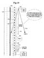
- FIG. 5is a plan view of a divided multi-lane vehicle pathway and depicts how periodic light intensity measurements may be made as a vehicle traverses the vehicle pathway over time and the discrete locations where such periodic light intensity measurements are performed by a data acquisition vehicle operating in accordance with the present invention.
- FIG. 6depicts four digital frames of data as captured by the intensity sensor at various discrete locations along the vehicle pathway depicted in FIG. 5 .
- FIG. 7depicts a flowchart showing the steps required to convert intensity measurements into foreground and background retroreflectivity for a single reflective asset.
- FIG. 8depicts a typical light source intensity profile over the visible electromagnetic spectrum, which illustrates how different wavelengths of electromagnetic radiation possess different light intensities.
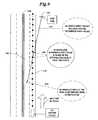
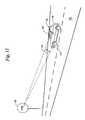
- FIG. 9depicts a preferred methodology for creating a retroreflectivity profile for all lanes and locations adjacent a vehicle pathway for a single reflective asset or sign which retroreflectivity profile is based upon a single pass of a data acquisition vehicle over the vehicle pathway.
- FIG. 10illustrates the facts that the normal vector of a reflective asset and the sheeting type of such a reflective asset create symmetry that may be used to determine retroreflectivity values along all rays (or vectors) that have the same relative angle to the normal vector of the reflective asset.
- FIG. 11depicts the concept of observation angle (i.e., angle between incident light from a light source and an human observer (or light sensor), of the light as reflected from the face of a reflective asset) in the context of a conventional passenger vehicle traversing a vehicle pathway and where light from the vehicle reflects from a stop sign to the vehicle operator (shown in ghost).
- observation anglei.e., angle between incident light from a light source and an human observer (or light sensor), of the light as reflected from the face of a reflective asset
- FIG. 12depicts the concept of entrance angle (i.e., angle between incident light from a light source mounted to a vehicle and a normal vector relative to the substantially flat face of a reflective surface disposed adjacent a vehicle pathway).
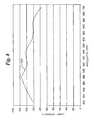
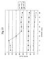
- FIG. 13is a graphic representation of the retroreflectivity performance for white sheeting for the three main types of sign sheeting.
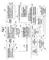
- FIGS. 14A and 14Bdepict a flowchart for a preferred embodiment of the threshold algorithm used to determine sign sheeting type.
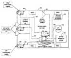
- an acquisition vehicle 10is equipped with multiple video cameras 12 that generate a series of raw videostreams 14 representative of a road or street over which the acquisition vehicle 10 is traveling.
- a global positioning satellite (GPS) receiver 16supplies location information that is combined with the raw videostream 14 by a processor 18 to generate a tagged videostream 20 .
- GPSglobal positioning satellite
- the tagged videostream 20is analyzed by a computer processor 22 to identify each road sign 30 and generate an asset management database 24 containing attribute and location information associated with each road sign 30 .
- the identification of road signs 30 and generation of asset management database 24is accomplished by the same processor 18 that tags the raw videostream 14 . The details of this process are set out in U.S. Pat. No. 6,453,056, issued Sep. 17, 2002 to Laumeyer et al., which is hereby incorporated by reference.
- the computer processor 22evaluates that portion 32 of each video frame or image that depicts a road sign 30 to determine a set of color values 40 , 42 for each of a plurality of colors on the road sign 32 .
- a retroreflectivity valueis generated for each color portion 34 , 36 on each frame of the tagged videostream 20 containing the road sign 30 that represents a different color value 40 , 42 .
- the values for retroreflectivityare determined by measuring the intensity of the signal for each color portion 34 , 36 .
- These valuesare then analyzed over the number of frames containing each color portion 34 , 36 to arrive at the maximum retroreflectivity value 44 , 46 that corresponds to the color value 40 , 42 for each color portion 34 , 36 of the road sign 30 .
- These maximum retroreflectivity values 44 , 46will be the reference values used in the threshold algorithm from which sign sheeting classification will be determined.
- Type Icommonly called Engineer Grade
- Type IIIcommonly called High Intensity
- Type VIIcommonly called Prismatic
- Prismaticis sometimes divided into two groups—Type VIIa called Diamond Grade VIP, and Type VIIb called Diamond Grade LDP.
- the automated system of the present inventionIn order to remove the manual element of determining sheeting type and measuring retroreflectivity, the automated system of the present invention must accurately distinguish between these sheeting types. To accomplish this, the present invention utilizes the fact that all signs use the same sheeting type for foreground and background colors, that each road sign will have at least two colors and that the reflectivity for each color for each type of sheeting material has a relatively unique minimum initial retroreflectivity value.
- each color of the three sheeting typeshas a minimum initial retroreflectivity value.
- the following tablelists the minimum values for common colors of each type:
- This informationis stored in a reflectivity/color database 50 .
- the computer processor 22accesses the database 50 using the maximum reflectivity value 44 , 46 that corresponds to the color value 40 , 42 for each color portion 34 , 36 to determine the lowest possible sheeting type for each color. If the sheeting type is classified the same for all of the color portions 34 , 36 for a given road sign 30 , then the sheeting class 52 is established as that type and this information is preferably stored in the asset management database 24 along with other attributes of the given road sign 30 .
- a subsequent analysis by the processor 22 using, for example, a neural network programto incorporate other determining factors, such as time of day, shadow, direction that could affect the retroreflectivity of the lighter colors (white, yellow and orange) more than the retroreflectivity of the darker colors (red, green, blue).
- retroreflectivity values for lighter colorsare weighted more heavily in resolving any discrepancies in classification of sheeting material.
- the system described hereinacquires many data points along the desired roadway without specifically targeting any objects of interest.
- the specific geometry of the sign(its orientation with respect to the roadway) is not necessarily known, nor is it required.
- the retroreflectivity points determined along the roadwayare generated for the “as placed” road sign.
- Road signswill display their best retroreflectivity performance (have the highest retroreflectivity values) at or near the normal vector for the sign face. Since the geometry of the as-measured sign is not known, the system chooses the highest retroreflectivity value for that sign as the value that will be used in the threshold algorithm for sign sheeting classification.
- Sign sheeting typesvary by the intensity of light that is reflected, but they also have reflective characteristics that give them unique signatures.
- FIG. 13shows the profiles for Type I, Type III, and Type VII white sign sheeting types. Note the unique profiles for the three sheeting types.
- the preferred embodiment of the present inventiondue to its ability to utilize multiple retroreflectivity points, can determine sheeting type by matching the as-measured profile with a uniformly reduced (where the entire curve is multiplied by a scaling factor that is less than one) characteristic curve that best correlates to the as-measured profile. This correlation step will establish the “best fit” performance curve based on the shape of the curve, without consideration for the magnitude of the curve.
- This “uniform reduction” of the sign sheeting performance curveallows the proper sheeting type to be determined, thus overcoming the problem with signs that have some type of surface anomaly.
- the performance curve correlation described abovecan be used in one of two ways—either as a validation of the proper determination of sheeting type from the threshold algorithm or as one of the qualification criteria prior to performing the threshold algorithm.
- the sheeting typesare all manufactured with multiple layers.
- the sheeting determination system described hereintests for the absence of these gross failures prior to making any R A measurements as part of the process of categorizing sheeting type.
- Retroreflectivitydesignated as “R A ” generally (and from time to time in this disclosure), varies according to two key parameters, observation angle and entrance angle.
- Observation angle 100(See FIG. 11 ) is the angular displacement between a light source 110 and a light sensor 120 , as measured from an object face surface 130 .
- observation angle 100is defined by the distance of the vehicle 140 from a sign face surface 130 , the placement of the light source (headlights) 110 on the vehicle 140 , and the position of the light sensor (eyes of the vehicle operator) 120 of the vehicle 140 .
- Entrance angle 160(See FIG. 12 ) is defined as the angular displacement of the incident light 170 relative to the normal vector 180 from the object face surface 130 . Entrance angles are impacted by the angular position 200 of a sign 190 relative to the highway 150 , the sign 190 lateral distance 210 from the highway 150 , and the distance 220 of the vehicle 140 from the sign 190 .
- the inventors hereofare believed to be the first persons to successfully decrease the complexity and increase the efficiency of determination of R A in the field.
- the method of automated determination of R Apreferably utilizes a plurality of subsystems located on/in a capture vehicle 225 .
- These subsystemsinclude a light intensity measurement system 230 , a vehicle positioning system 240 , a color image capture system 250 and a data recording system 260 .
- the light intensity measurement system 230preferably includes a high output light source 270 , a light intensity sensor 280 and an intensity measurement system control 290 .
- a plurality of intensity measurements 300are generated by the intensity measurement system 230 in response to the repeated strobing of the high output light source 270 .
- the vehicle positioning system 240preferably includes a GPS receiver 310 , an inertial navigation system 320 , a distance measuring instrument 330 and a master clock 340 .
- a position measurement 350is generated by the vehicle positioning system 240 .
- the color image capture system 250preferably includes a stereoscopic camera pair 360 , iris controls 370 and image capture control 380 .
- the image capture system 250generates a digital imagery stream 390 .
- the data required for the automated determination of R Ais accumulated while traversing a highway 150 with the capture vehicle 225 (See FIGS. 5 and 6 ).
- the capture vehicle 225is shown on a 4-lane divided highway 400 with the capture vehicle 225 located in a proximate lane 410 to the stop sign 190 .
- a series of reflected light intensity frames 420are generated at a constant measurement interval 430 as the capture vehicle travels along the highway 150 .
- Characterization of sign 190 R Apreferably utilizes the data recording system 260 to create a single tagged videostream 440 from the reflected light intensity frames 420 , position measurements 350 and digital imagery 390 for each capture event 430 (See FIGS. 3 , 5 , 6 , 7 , and 8 ).
- a computer processor 450identifies an object of interest 460 in a portion of the intensity frame 420 and determines the object of interest attributes 465 associated with that object of interest.
- the objects of interestare identified from the digital imagery stream 390 generated by the color image capture system 250 in the manner as taught by U.S. Pat. No. 6,266,442.
- the computer processor 450correlates the portion of an image frame of the digital imagery stream 290 with a similar portion of the intensity frame 420 containing the object of interest 460 .
- a background intensity measurement 470 and a foreground intensity measurement 480is generated.
- the computer processor 450determines a background luminance value 500 and a foreground luminance value 510 . Based on the background luminance value 500 , the foreground luminance value 510 , a characterization of light source wavelength 540 , the background sheeting color 505 and the foreground sheeting color 506 the computer processor 450 characterizes a background R A 520 and a foreground R A 530 which are preferably reported separately for that object of interest.
- the automated determination of multiple R A values for a given object of interest 460allows for the extrapolation of R A values at an unmeasured viewing point 550 for an object of interest, such as a sign 190 (See FIGS. 9 and 10 ).
- the unmeasured viewing pointresides in a nontraversed lane 560 .
- the computer processor 450defines an undetermined retroreflectivity ray 570 for unmeasured viewing point 550 .
- the computer processor 450determines an R A value for unmeasured viewing point 550 and any point located along undetermined retroreflectivity ray 570 .
- a method and apparatus for determining retroreflectivity of relatively flat surface portions of objects disposed adjacent a highway 150 traversed by a vehicle 140are taught, enabled, and depicted.
- the present inventionmay be utilized to detect and determine a retroreflective surface of interest disposed in a scene of non-retroreflective surfaces. That is, at least one object face surface 130 which exhibits retroreflectivity over at least a relatively narrow conical volume of magnitude of several degrees from a normal vector 180 originating from said object face surface 130 .
- a determination of the retroreflectivity of objects adjacent a highway 150preferably includes providing: (i) position measurements 350 of a capture vehicle 225 ; (ii) precise position of the object of interest 460 , or sign 190 ; (iii) intensity measurements 300 from a high output light source 270 and light intensity sensor 280 at measurement intervals 430 along said highway 150 .
- a single-pass along the highway 150 by the capture vehicle 225 operating the light intensity measurement system 230 , vehicle positioning system 240 , image capture system 250 and data recording system 260 taught hereineliminates many shortcomings of the prior art and allows a single vehicle operator to conduct virtually continuous data measurement and acquisition of objects of interest 460 disposed adjacent a highway 150 , at capture events 430 on said highway 150 , without disrupting or interrupting other vehicle traffic traversing said highway 150 .
- FIG. 3shows a block diagram of the on-board systems and the desktop systems required to record a tagged videostream 440 and create sign R A profiles 590 for various signs 190 along a highway 150 .
- the vehicle positioning system 240contains all of the equipment to precisely locate the capture vehicle 225 . All location information is synchronized with a master clock 340 preferably associated with a computer processor 450 , which allows other data types to be merged with the vehicle location information at later stages in the post-processing.
- All of the on-board systemsutilize the same master clock 340 information, thus allowing any events (image capture system 250 , intensity measurement 300 , and trigger controls 227 , 228 ) to be correlated to the precise vehicle location and attitude during real-time, near real-time, or post-processing of the data acquired by the capture vehicle 225 .
- the image capture system 250consists of at least one set of stereoscopic cameras 360 that gather digital imagery along the highway 150 . Each capture event is combined with time stamp information from the vehicle positioning system 240 which also provides trigger control 227 for the image capture system 250 and trigger control 228 for the light intensity measurement system 230 . These images and associated time stamps are later combined with photogrammetry to create objects of interest 460 and their associated attributes 465 .
- the light intensity measurement system 230preferably consists of at least one high output light source(s) 270 and the associated light intensity sensor(s) 280 .
- the precise control for these itemsis contained within the light intensity measurement system 230 , and master time sequencing instrument 340 information received from the vehicle positioning system 240 (or computer processor 450 ) is combined to create a tagged videostream 440 so precise vehicle information can be utilized during post-processing.
- the data recording system 260is constantly monitoring control information from the other three on-board systems and records the necessary information. No post-processing is performed in the data recording system 260 . As computer power increases in the future, one skilled in the art could produce a system whereby most, if not all, of the post-processing functions were performed in the capture vehicle 225 , perhaps even in real time. The inventors can imagine several uses for the production of real-time information from the image capture system 250 in the future, but the cost of obtaining such information with today's computing power makes this option prohibitively expensive today.
- FIG. 3shows the functional blocks for data post-processing.
- the specific steps required to compute R Aare outlined in the discussion below.
- FIG. 4shows a typical configuration within a capture vehicle that is capable of producing data and imagery to create digital representations of objects of interest 460 and objects of interest retroreflectivity 466 .
- the distance measuring instrument (DMI) 330 , GPS receiver 310 and inertial navigation system (INS) 320constitute the vehicle positioning system 240 . Not all of these components are necessary to obtain the desired results, but better precision, and therefore more meaningful data, are produced if all three components are included.
- the high output light source(s) 270 and light intensity sensor(s) 280constitute the light intensity measurement system 230 . These components make it possible to gather on-the-fly information for a desired highway 150 to allow the computation of object of interest retroreflectivity 466 , as well as create a full 3-D sign R A profile 590 for those same objects of interest 460 .
- the stereoscopic cameras 360constitute the digital imagery system 390 that allows for the creation of objects of interest 460 and their associated attributes 465 during post-processing. More than one set of stereoscopic cameras 360 can be employed, thus increasing the accuracy of positional measurements for objects of interest 460 .
- Other, non-stereoscopic imaging systemscould also be employed with little or no change to the vehicle positioning system 240 or to the light intensity measurement system 230 .
- FIG. 5shows the top view of a 4-lane divided highway 400 with a stop sign 190 .
- the capture vehicle 225is traveling in the proximate lane 410 to the stop sign 190 and makes intensity measurements 300 at capture events 430 while traveling the depicted route.
- the techniques described hereinwill allow a retroreflectivity value for this stop sign 190 to be computed for any point along the 4-lane divided highway 400 , independent of whether the intensity measurement 300 was made at that point and also independent of whether the capture vehicle 225 actually drove over that point.
- intensity measurements 300are made continuously while the capture vehicle 225 is in motion, thus requiring no prior knowledge of either the positions or the existence of signs.
- FIG. 6shows some typical reflected light intensity frames 420 as captured by the light intensity sensor 280 at various discrete locations along the roadway. These reflected light intensity frames 420 are the result of the high output light source 270 being energized (or flashed) while each reflected light intensity frame 420 is captured by one or more light intensity sensors 280 . Since most of the objects in the scene are not reflective, and due to the high setting of the threshold range in the light intensity sensor(s) 280 , the reflected light intensity frames 420 will actually show very few objects. For effective luminance results throughout a wide range of retroreflective materials, more than one light intensity sensor 280 may be required in order to get enough levels of gray within the active part of the visible spectrum. When multiple light intensity sensors 280 are required or used, they may each have different threshold ranges and each thus detect luminance values in different parts of the desired luminance ranges.
- Luminance(expressed in candelas per square meter, or cd/m 2 ) will vary according to the intensity sensor characterization profile 275 of the light intensity sensor(s) 280 and the color of the material from which light is reflected.
- roadway signs 190contain text and/or symbols overlaid on a background. To ensure maximum visibility during day and night conditions, the colors of the foreground information (text and/or symbols) are chosen to have maximum day and night contrast with the background material.
- the techniques taught hereinallow the retroreflectivity of roadway signs 190 to be determined for both foreground and background materials. Computing both the foreground 530 and background retroreflectivity 520 for each object of interest 460 allows us to ensure that the proper nighttime contrast is achieved for roadside assets. For example, a stop sign 190 with a red background and white lettering can provide good daytime contrast between the text and the sign background. But if these two materials display very similar retroreflectivity characteristics, their nighttime contrast will be minimal, thus rendering the sign ineffective during nighttime conditions.
- FIG. 7shows a block diagram of the steps required to transform intensity measurements 300 into foreground luminance values 510 and background luminance values 500 .
- a black and white camerais preferably used as a light intensity sensor 280 to maximize the sensitivity of intensity measurements 300 (intensity will be determined from the gray value of the corresponding pixels).
- an intensity measurement 300is intensity values for N discrete points within the scene, where N corresponds to the number of pixels in the light intensity sensor's 280 array.
- an intensity sensor measurement 300in the form of an array of discrete pixel intensity values, preferably a single pixel intensity value is selected and utilized for the automated determination of a corresponding retroreflectivity value.
- an average or other combination of a group of pixel intensity valuescould be utilized for the automated determination of a corresponding retroreflectivity value.
- Intensity valueswill vary according to the color of the reflected light, since not all colors of incoming light excite the light intensity sensor 280 pixels in the same way.
- the intensity value 300 for a particular colorcan be converted into a luminance value.
- Light intensity sensor 280 characterizationis essential for high precision computations since N photons of a given particular color (or wavelength) of light will represent a different gray value (intensity level) in the sensor than N photons of another color (or wavelength) of light.
- the look-up-table (LUT) 475 shown in FIG. 7is a digital table stored in memory that uses the indexes of intensity (a single gray level value from the intensity measurement 300 ) and sheeting color to determine the luminance.
- the light intensity sensor characterization 275is empirical information about the light intensity sensor 280 that is used to create the LUT 475 .
- the same LUT 475is used for computing foreground 510 and background luminance values 500 .
- FIG. 7shows the information needed to accurately convert luminance to R A : sensor location, object location, light source characterization, and color of reflective material. For less precise R A computations, a subset of the aforementioned characteristics can be utilized.
- the sheeting color and luminance valuemay be used to determine a rough approximation (within 20%, for example) for R A .
- the characterization of light source angledefines the amount of light emitted from the high output light source 270 throughout the source's field of view. Due to the limitations of lamp design and their associated reflectors, most semi-uniform light sources will have their greatest intensity at or near the normal vector for the light source. Since the high output light source(s) 270 are not aimed at objects of interest 460 , the part of the incident light beam that is striking the object of interest 460 when the intensity measurement 300 is captured must be determined. Light source angle characterization is a process whereby empirical data from the light is modeled to establish the light intensity for numerous discrete vectors from the center of the light.
- the light intensity sensor 280 location and heading, as well as the object of interest 460 locationare used to determine which light vector emanating from the light source was responsible for the resulting intensity measurement.
- the characterization of light source angletherefore, is a look-up-table where an object of interest's 460 angular displacement from the normal vector 180 for the high output light source 270 is converted to a light intensity for the associated vector.
- the characterization of light source angleis constructed at a few discrete distances from the light. Simple geometry can be used to compute the incident radiation (using an interpolation method for an actual distance between two discrete distances in the characterization of light source angle) hitting the actual object of interest 460 based on the empirical data from the characterization of light source angle.
- the preferred high output light source 270is a uniform full-spectrum (visible spectrum) light. In practice, this light source will not emit the same intensity for all wavelengths of visible light.
- One variable of light source color characterization that should be consideredis the output profile of the light throughout the visible spectrum.
- FIG. 8shows a typical full-spectrum light source output profile. Note that the intensity in the blue area (400-500 nm) of the spectrum is stronger than in the red area (600-700 nm). This profile specifies the amount of light energy (number of photons) emitted for a given frequency.
- R Adepends on the intensity of the incident light
- the light source color characterization 540 , light source angle characterization 535 , background sheeting color 505 and foreground sheeting color 506must be combined to determine how the background luminance value 500 and foreground luminance value 510 is converted to R A (i.e., what percent of the incident photons of the foreground/background color were reflected back to the sensor).
- the divergence pattern for the light sourcemay have different profiles for various portions of the visible spectrum.
- a separate light source angle characterization profilemay be required for each possible foreground and background color of any given object of interest 460 .
- a preferred high output light source 270is of the type set forth in the attached installation and operation guide entitled “StrobeGuardTM High Intensity Obstruction Lighting System, Model No. SG-60,” manufactured by Honeywell, Inc.
- intensity measurements 300 for frequent capture events 430 along a highway 150 while the capture vehicle 225 is in motionFor example, at vehicle speeds of 50 miles per hour, intensity measurements 300 should be taken at a rate of at least two per second.
- the StrobeGuardTM SG-60 modelhas a recharge time of about 1.5 seconds between successive flash events. As a result, one SG-60 light will not provide enough flash events per second to allow an adequate number of intensity measurements 300 .
- three of the StrobeGuardTM SG-60 unitswould need to be fired in a synchronized, round-robin pattern to obtain enough trigger events.
- the light intensity measurement system 230 described hereinattempts to remove observation angle 100 as an R A variable. This is done by keeping the offset between the high output light source(s) 270 and light intensity sensor(s) 280 as low as possible. As mentioned previously, an R A profile of a simulated roadway 580 can be computed, even though the intensity was not measured at every point and even though the capture vehicle 225 did not drive over every point. First, it is critical that the geometry of R A is understood. Reflective materials like sign sheeting are designed to project near-columnated light back toward the light source. If a perfectly columnated light being reflected from the object of interest 460 being measured and a zero observation angle are assumed, the R A values for all discrete locations along a ray projected from the object will be identical.
- FIG. 9shows how to compute R A for any discrete location along a 4-lane divided highway 400 .
- the R A value for the desired pointwill be based on the R A value that lies along the pathway traveled by the data acquisition vehicle 225 .
- an undetermined retroreflectivity ray 570is drawn from the desired location to the face of the reflective asset.
- the discrete location where the undetermined retroreflectivity ray 570 intersects the vehicle pathwill be used as the reference R A value. Since the discrete location on the vehicle path will always lie between two measured locations where intensity measurements 300 were made, the reference R A value is computed by interpolating the two closest (in distance) R A values along the vehicle path.
- interpolatehas the usual and typical meaning. It will be understood that interpolation consistent with the present invention can involve interpolation followed by extrapolation and shall also include such other special mathematical expressions used or created to account for border effects and effects at the lateral periphery and at the furthest distance where R A may be reliably determined by application of the teaching of this disclosure.
- R A at the desired pointwill be the same as the reference R A value.
- all sign 190 sheeting materialswill have some beam divergence for reflected light. This beam divergence information can be used to adjust the computed R A value up (or down) from the reference R A value for discrete locations closer to (or farther from) the object's face surface 130 .
- the “assumption” methodrequires that the normal vector 180 from the surface of the sign 190 is assumed to be parallel to the capture vehicle pathway 410 at the nearest location of the capture vehicle pathway 410 to the sign 190 .
- a scanning laser operating in conjunction with an optical sensor and having a common field of viewmay be used to more precisely resolve the normal vector 180 from the object's face surface 130 .
- stereoscopic cameras 360may be employed in a useful, albeit very imprecise manner of determining the normal vector 180 .
- the assumption method and stereo imaging methodmay be combined whereby the normal vector 180 is assumed to lie parallel to the vehicle pathway 410 unless the stereo imaging output renders the assumption false.
- the highest precision measuring systems for determining the normal vector 180consists of a scanned laser and associated optical sensor. This combination yields relative distance measurements between the capture vehicle 225 and the object's face surface 130 that are more precise than optical measurements with cameras.
- a laser scanner attached to the capture vehicle 225 and directed toward a roadside scene populated with retroreflective signs 130generates a series of reflection points to the optical sensor that appear as a horizontal segment of points.
- the optical sensormust be fast enough (i.e., have adequate data acquisition rates) to capture at least several individual discrete measurements across the object's face surface 130 (or of any other reflective asset).
- two types of laser scannersare suitable to be utilized according to the present invention; namely, single-axis scanners and dual-axis scanners.
- a preferred sensoris of the type set forth in the proposal entitled, “Holometrics 3-D Vision Technology,” as referenced in the previously identified provisional patent application.
- a single-axis laser scannercannot be mounted such that the scanning laser beam covers only a single elevation or constant height relative to the highway 150 and the capture vehicle 225 . Rather, the inventors hereof suggest that use of a single-axis type laser scanner must either be mounted high on the capture vehicle 225 with a downward facing trajectory, or be mounted low on the capture vehicle 225 with an upward facing scanning trajectory.
- Dual-axis laser scanners 335circumvent the varying sign height problem inherently encountered if a single-axis laser scanner is employed as the source of integrated energy when practicing the teaching of the present invention.
- a dual-axis laser scanner 335operates by continuously moving the scanning beam scan up and down at a relatively slow rate while sweeping the laser beam laterally from side to side across the field of view at a relatively more rapid rate.
- Either of the scanning methodsproduces a massive number of sensed discrete locations representing discrete reflections of the incident laser radiation and each must be processed in order to correlate each of the sensed discrete locations with the object's face surface 130 .
- simple triangulation methodsare used to combine: (i) the vehicle location, (ii) vehicle heading vector, and (iii) scanned sign point to ultimately determine the normal vector 180 for the object's face surface 130 .
- the retroreflective properties of sign 190 sheeting materialsare typically symmetrical about the vertical axis of the object's face surface 130 . Because of this symmetry, R A values (either computed or extrapolated/interpolated values) will be identical for rays that are symmetrical about the vertical axis.
- FIG. 10shows how the sign's 190 normal vector 180 can be used to extrapolate more R A points.
- the R A value for Point Bis the same as the R A value for Point A since their angle relative to the normal vector 180 is the same and since their distance from the sign 190 is the same. If Point B has the same relative angle (from the sign's 190 normal vector 180 ) as Point A, but lies closer to (or farther from) the object's face surface 130 , the sign 190 material's beam divergence profile can be used to adjust the R A value for Point B up (or down) from the value obtained for Point A.
- the image capture system 250 and light intensity measurement system 230are preferably free running, with measurements being made periodically during capture vehicle 225 operation. There is no requirement that these two systems be synchronized. In fact, these systems could operate in completely different capture vehicles 225 , if necessary. When both systems are contained within the same capture vehicle 225 , the only constraint for simultaneous operation is placed on the image capture system 250 . Because of the intensity of the high output light source 270 in the light intensity measurement system 230 , it is preferred that the image capture system 250 not capture frames at the same instant that the high output light source 270 is triggered. If images are actually captured while the high output light source 270 is triggered, their positional results would still be valid, but the colors displayed would be inaccurate because of the high output light being directed toward the (typically lower-thresholded) stereoscopic cameras 360 .
- One skilled in the artcould completely eliminate any need for the image capture system 250 to know the firing events of the light intensity measurement system 230 by choosing sampling rates for the two systems that do not share any harmonic frequencies.
- the skilled implementercould use time stamps to determine when this system simultaneity occurred and discard the imaging frames.
- each road sign 30has only two colors of reflective sheeting and that the sheeting type is the same for both the background sheeting color 505 and the foreground sheeting color 506 . It is also assumed that the retroreflectivity for both the background R A 520 and the foreground R A 530 are non-zero values.
- the algorithmassumes that prefiltering has eliminated retroreflectivity values for road signs 30 that demonstrate some type of gross failure of the sheeting material, such as delamination, excessive surface wear, extreme color fade, vapor fade, graffiti, or excessive dirt or other obstructions that would prevent an accurate determination of the retroreflectivity value.
- Such filteringis preferably accomplished by image analysis of the color images using any number of known image analysis techniques for characterizing anomalies in images.
- the sign sheeting threshold algorithm processis initiated at step 600 .
- the background sheeting color 505is compared to a series of known sign sheeting colors. If the background color is yellow-green as determined at step 610 , then the sign sheeting type is classified as Type VII as step 628 . If the background color is white as determined at step 612 , then the background R A 520 is compared to the maximum retroreflectivity values for different sheeting types at steps 630 , 632 . If the background R A 520 is less than the maximum white retroreflectivity value for sheeting Type I as determined at step 630 , then the sign sheeting type is classified as Type I at step 634 .
- the sign sheeting typeis classified as Type III at step 636 . If neither steps 630 or 632 are satisfied, then the sign sheeting type is classified as Type VII at step 638 .
- a similar processis repeated for colors yellow at step 614 and steps 640 , 642 , orange at step 616 and steps 644 , 646 , red at step 618 and steps 650 , 652 .
- step 660determines whether the foreground color 506 is white and at step 670 whether the foreground color is yellow. If step 660 is satisfied, then the foreground R A 520 is compared to the maximum retroreflectivity values for different sheeting types at steps 662 , 664 . If the foreground R A 530 is less than the maximum white retroreflectivity value for sheeting Type I as determined at step 662 , then the sign sheeting type is classified as Type I at step 666 .
- the sign sheeting typeis classified as Type III at step 668 . If neither steps 662 or 664 are satisfied, then the sign sheeting type is classified as Type VII at step 669 . A similar process is repeated for the yellow foreground color at steps 672 and 674 .
- the sign sheeting typeis considered undetermined at step 680 . It will be understood that various options can be undertaken at step 680 , including obtaining another color image and set of retroreflectivity values for the given road sign either with or without additional filtering or preprocessing of the raw data, marking the image and data for further review by an operator, discarding the information and marking the road sign as needing manual investigation, marking the road sign as needing replacement, or any combination of these or other operations.
- the threshold algorithmcould utilize either minimum or maximum retroreflectivity values.
- the combinations and orders of comparison of the colors and foreground or background colorsmay be altered and additional comparisons may be made to accommodate additional sheeting types that may be developed.
- the colors 505 and 506are determined based on CIELUV color values as evaluated by the image capture system 250 .
- other equivalent color value systemssuch as RGB could be used for the color values.
- the color values for the comparisonsare a range of values specified by the manufacturer of the sheeting material.
- the color values for the comparisoncan be ranges of values empirically established.
Landscapes
- Physics & Mathematics (AREA)
- General Physics & Mathematics (AREA)
- Life Sciences & Earth Sciences (AREA)
- Engineering & Computer Science (AREA)
- Atmospheric Sciences (AREA)
- Immunology (AREA)
- Chemical & Material Sciences (AREA)
- Analytical Chemistry (AREA)
- Biochemistry (AREA)
- General Health & Medical Sciences (AREA)
- Health & Medical Sciences (AREA)
- Pathology (AREA)
- Electromagnetism (AREA)
- Theoretical Computer Science (AREA)
- Multimedia (AREA)
- Spectroscopy & Molecular Physics (AREA)
- Computer Networks & Wireless Communication (AREA)
- Radar, Positioning & Navigation (AREA)
- Remote Sensing (AREA)
- Image Analysis (AREA)
- Investigating Or Analysing Materials By Optical Means (AREA)
- Traffic Control Systems (AREA)
Abstract
Description
| Type I | Type III | Type VIIa | Type VIIb | |||
| Color | Min. RA | Min. RA | Min. RA | Min. RA | ||
| White | 70 | 250 | 430 | 800 | ||
| 50 | 170 | 350 | 660 | |||
| 25 | 100 | 200 | 360 | |||
| Red | 14.5 | 45 | 110 | 215 | ||
| Green | 9 | 45 | 45 | 80 | ||
| Blue | 4 | 20 | 20 | 43 | ||
Claims (3)
Priority Applications (8)
| Application Number | Priority Date | Filing Date | Title |
|---|---|---|---|
| US12/419,843US7995796B2 (en) | 2000-08-12 | 2009-04-07 | System for road sign sheeting classification |
| US13/205,337US8660311B2 (en) | 2000-08-12 | 2011-08-08 | System for assessment reflective objects along a roadway |
| US13/781,017US9989456B2 (en) | 2000-08-12 | 2013-02-28 | System for the determination of retroreflectivity of road signs and other reflective objects |
| US14/025,614US8860944B2 (en) | 2000-08-12 | 2013-09-12 | System and assessment of reflective objects along a roadway |
| US14/512,735US9335255B2 (en) | 2000-08-12 | 2014-10-13 | System and assessment of reflective objects along a roadway |
| US15/148,722US9671328B2 (en) | 2000-08-12 | 2016-05-06 | System and assessment of reflective objects along a roadway |
| US15/595,594US9989457B2 (en) | 2000-08-12 | 2017-05-15 | System and assessment of reflective objects along a roadway |
| US15/993,883US20180372621A1 (en) | 2000-08-12 | 2018-05-31 | System and assessment of reflective objects along a roadway |
Applications Claiming Priority (5)
| Application Number | Priority Date | Filing Date | Title |
|---|---|---|---|
| US22476100P | 2000-08-12 | 2000-08-12 | |
| US29659601P | 2001-06-07 | 2001-06-07 | |
| US09/928,218US6891960B2 (en) | 2000-08-12 | 2001-08-10 | System for road sign sheeting classification |
| US11/056,926US7515736B2 (en) | 2000-08-12 | 2005-02-11 | System for road sign sheeting classification |
| US12/419,843US7995796B2 (en) | 2000-08-12 | 2009-04-07 | System for road sign sheeting classification |
Related Parent Applications (1)
| Application Number | Title | Priority Date | Filing Date |
|---|---|---|---|
| US11/056,926ContinuationUS7515736B2 (en) | 2000-08-12 | 2005-02-11 | System for road sign sheeting classification |
Related Child Applications (1)
| Application Number | Title | Priority Date | Filing Date |
|---|---|---|---|
| US13/205,337DivisionUS8660311B2 (en) | 2000-08-12 | 2011-08-08 | System for assessment reflective objects along a roadway |
Publications (2)
| Publication Number | Publication Date |
|---|---|
| US20090252376A1 US20090252376A1 (en) | 2009-10-08 |
| US7995796B2true US7995796B2 (en) | 2011-08-09 |
Family
ID=27397401
Family Applications (10)
| Application Number | Title | Priority Date | Filing Date |
|---|---|---|---|
| US09/928,218Expired - LifetimeUS6891960B2 (en) | 2000-08-12 | 2001-08-10 | System for road sign sheeting classification |
| US11/056,926Expired - LifetimeUS7515736B2 (en) | 2000-08-12 | 2005-02-11 | System for road sign sheeting classification |
| US12/419,843Expired - Fee RelatedUS7995796B2 (en) | 2000-08-12 | 2009-04-07 | System for road sign sheeting classification |
| US13/205,337Expired - Fee RelatedUS8660311B2 (en) | 2000-08-12 | 2011-08-08 | System for assessment reflective objects along a roadway |
| US13/781,017Expired - LifetimeUS9989456B2 (en) | 2000-08-12 | 2013-02-28 | System for the determination of retroreflectivity of road signs and other reflective objects |
| US14/025,614Expired - Fee RelatedUS8860944B2 (en) | 2000-08-12 | 2013-09-12 | System and assessment of reflective objects along a roadway |
| US14/512,735Expired - Fee RelatedUS9335255B2 (en) | 2000-08-12 | 2014-10-13 | System and assessment of reflective objects along a roadway |
| US15/148,722Expired - Fee RelatedUS9671328B2 (en) | 2000-08-12 | 2016-05-06 | System and assessment of reflective objects along a roadway |
| US15/595,594Expired - Fee RelatedUS9989457B2 (en) | 2000-08-12 | 2017-05-15 | System and assessment of reflective objects along a roadway |
| US15/993,883AbandonedUS20180372621A1 (en) | 2000-08-12 | 2018-05-31 | System and assessment of reflective objects along a roadway |
Family Applications Before (2)
| Application Number | Title | Priority Date | Filing Date |
|---|---|---|---|
| US09/928,218Expired - LifetimeUS6891960B2 (en) | 2000-08-12 | 2001-08-10 | System for road sign sheeting classification |
| US11/056,926Expired - LifetimeUS7515736B2 (en) | 2000-08-12 | 2005-02-11 | System for road sign sheeting classification |
Family Applications After (7)
| Application Number | Title | Priority Date | Filing Date |
|---|---|---|---|
| US13/205,337Expired - Fee RelatedUS8660311B2 (en) | 2000-08-12 | 2011-08-08 | System for assessment reflective objects along a roadway |
| US13/781,017Expired - LifetimeUS9989456B2 (en) | 2000-08-12 | 2013-02-28 | System for the determination of retroreflectivity of road signs and other reflective objects |
| US14/025,614Expired - Fee RelatedUS8860944B2 (en) | 2000-08-12 | 2013-09-12 | System and assessment of reflective objects along a roadway |
| US14/512,735Expired - Fee RelatedUS9335255B2 (en) | 2000-08-12 | 2014-10-13 | System and assessment of reflective objects along a roadway |
| US15/148,722Expired - Fee RelatedUS9671328B2 (en) | 2000-08-12 | 2016-05-06 | System and assessment of reflective objects along a roadway |
| US15/595,594Expired - Fee RelatedUS9989457B2 (en) | 2000-08-12 | 2017-05-15 | System and assessment of reflective objects along a roadway |
| US15/993,883AbandonedUS20180372621A1 (en) | 2000-08-12 | 2018-05-31 | System and assessment of reflective objects along a roadway |
Country Status (1)
| Country | Link |
|---|---|
| US (10) | US6891960B2 (en) |
Cited By (53)
| Publication number | Priority date | Publication date | Assignee | Title |
|---|---|---|---|---|
| US20100268466A1 (en)* | 2009-04-15 | 2010-10-21 | Velayutham Kadal Amutham | Anti-collision system for railways |
| US20100316252A1 (en)* | 2008-02-12 | 2010-12-16 | Fundacion Cidaut | Method For Determining The Luminance Of Traffic Signs And Device For Implementing Same |
| US20100328316A1 (en)* | 2009-06-24 | 2010-12-30 | Matei Stroila | Generating a Graphic Model of a Geographic Object and Systems Thereof |
| US20120065940A1 (en)* | 2000-08-12 | 2012-03-15 | Retterath James E | System for road sign sheeting classification |
| US9804264B2 (en) | 2015-11-30 | 2017-10-31 | Luminar Technologies, Inc. | Lidar system with distributed laser and multiple sensor heads |
| US9810786B1 (en) | 2017-03-16 | 2017-11-07 | Luminar Technologies, Inc. | Optical parametric oscillator for lidar system |
| US9810775B1 (en) | 2017-03-16 | 2017-11-07 | Luminar Technologies, Inc. | Q-switched laser for LIDAR system |
| US9841495B2 (en) | 2015-11-05 | 2017-12-12 | Luminar Technologies, Inc. | Lidar system with improved scanning speed for high-resolution depth mapping |
| US9869754B1 (en) | 2017-03-22 | 2018-01-16 | Luminar Technologies, Inc. | Scan patterns for lidar systems |
| US9905992B1 (en) | 2017-03-16 | 2018-02-27 | Luminar Technologies, Inc. | Self-Raman laser for lidar system |
| US9989629B1 (en) | 2017-03-30 | 2018-06-05 | Luminar Technologies, Inc. | Cross-talk mitigation using wavelength switching |
| US10003168B1 (en) | 2017-10-18 | 2018-06-19 | Luminar Technologies, Inc. | Fiber laser with free-space components |
| US10007001B1 (en) | 2017-03-28 | 2018-06-26 | Luminar Technologies, Inc. | Active short-wave infrared four-dimensional camera |
| US10061019B1 (en) | 2017-03-28 | 2018-08-28 | Luminar Technologies, Inc. | Diffractive optical element in a lidar system to correct for backscan |
| US10088559B1 (en) | 2017-03-29 | 2018-10-02 | Luminar Technologies, Inc. | Controlling pulse timing to compensate for motor dynamics |
| US10094925B1 (en) | 2017-03-31 | 2018-10-09 | Luminar Technologies, Inc. | Multispectral lidar system |
| US10114111B2 (en) | 2017-03-28 | 2018-10-30 | Luminar Technologies, Inc. | Method for dynamically controlling laser power |
| US10121813B2 (en) | 2017-03-28 | 2018-11-06 | Luminar Technologies, Inc. | Optical detector having a bandpass filter in a lidar system |
| US10139478B2 (en) | 2017-03-28 | 2018-11-27 | Luminar Technologies, Inc. | Time varying gain in an optical detector operating in a lidar system |
| US10191155B2 (en) | 2017-03-29 | 2019-01-29 | Luminar Technologies, Inc. | Optical resolution in front of a vehicle |
| US10209359B2 (en) | 2017-03-28 | 2019-02-19 | Luminar Technologies, Inc. | Adaptive pulse rate in a lidar system |
| US10241198B2 (en) | 2017-03-30 | 2019-03-26 | Luminar Technologies, Inc. | Lidar receiver calibration |
| US10254388B2 (en) | 2017-03-28 | 2019-04-09 | Luminar Technologies, Inc. | Dynamically varying laser output in a vehicle in view of weather conditions |
| US10254762B2 (en) | 2017-03-29 | 2019-04-09 | Luminar Technologies, Inc. | Compensating for the vibration of the vehicle |
| US10267899B2 (en) | 2017-03-28 | 2019-04-23 | Luminar Technologies, Inc. | Pulse timing based on angle of view |
| US10295668B2 (en) | 2017-03-30 | 2019-05-21 | Luminar Technologies, Inc. | Reducing the number of false detections in a lidar system |
| US10310058B1 (en) | 2017-11-22 | 2019-06-04 | Luminar Technologies, Inc. | Concurrent scan of multiple pixels in a lidar system equipped with a polygon mirror |
| US20190179018A1 (en)* | 2017-12-07 | 2019-06-13 | Velodyne Lidar, Inc. | Systems and methods for efficient multi-return light detectors |
| US10324170B1 (en) | 2018-04-05 | 2019-06-18 | Luminar Technologies, Inc. | Multi-beam lidar system with polygon mirror |
| US10340651B1 (en) | 2018-08-21 | 2019-07-02 | Luminar Technologies, Inc. | Lidar system with optical trigger |
| US10348051B1 (en) | 2018-05-18 | 2019-07-09 | Luminar Technologies, Inc. | Fiber-optic amplifier |
| US10401481B2 (en) | 2017-03-30 | 2019-09-03 | Luminar Technologies, Inc. | Non-uniform beam power distribution for a laser operating in a vehicle |
| US10451716B2 (en) | 2017-11-22 | 2019-10-22 | Luminar Technologies, Inc. | Monitoring rotation of a mirror in a lidar system |
| US10545240B2 (en) | 2017-03-28 | 2020-01-28 | Luminar Technologies, Inc. | LIDAR transmitter and detector system using pulse encoding to reduce range ambiguity |
| US10551501B1 (en) | 2018-08-09 | 2020-02-04 | Luminar Technologies, Inc. | Dual-mode lidar system |
| US10557939B2 (en) | 2015-10-19 | 2020-02-11 | Luminar Technologies, Inc. | Lidar system with improved signal-to-noise ratio in the presence of solar background noise |
| US10591601B2 (en) | 2018-07-10 | 2020-03-17 | Luminar Technologies, Inc. | Camera-gated lidar system |
| US10627516B2 (en) | 2018-07-19 | 2020-04-21 | Luminar Technologies, Inc. | Adjustable pulse characteristics for ground detection in lidar systems |
| US10641874B2 (en) | 2017-03-29 | 2020-05-05 | Luminar Technologies, Inc. | Sizing the field of view of a detector to improve operation of a lidar system |
| US10663595B2 (en) | 2017-03-29 | 2020-05-26 | Luminar Technologies, Inc. | Synchronized multiple sensor head system for a vehicle |
| US10677897B2 (en) | 2017-04-14 | 2020-06-09 | Luminar Technologies, Inc. | Combining lidar and camera data |
| US10684360B2 (en) | 2017-03-30 | 2020-06-16 | Luminar Technologies, Inc. | Protecting detector in a lidar system using off-axis illumination |
| US10732281B2 (en) | 2017-03-28 | 2020-08-04 | Luminar Technologies, Inc. | Lidar detector system having range walk compensation |
| US10873738B2 (en) | 2016-03-03 | 2020-12-22 | 4D Intellectual Properties, Llc | Multi-frame range gating for lighting-invariant depth maps for in-motion applications and attenuating environments |
| US10969488B2 (en) | 2017-03-29 | 2021-04-06 | Luminar Holdco, Llc | Dynamically scanning a field of regard using a limited number of output beams |
| US10976417B2 (en) | 2017-03-29 | 2021-04-13 | Luminar Holdco, Llc | Using detectors with different gains in a lidar system |
| US10983213B2 (en) | 2017-03-29 | 2021-04-20 | Luminar Holdco, Llc | Non-uniform separation of detector array elements in a lidar system |
| US11002853B2 (en) | 2017-03-29 | 2021-05-11 | Luminar, Llc | Ultrasonic vibrations on a window in a lidar system |
| US11022688B2 (en) | 2017-03-31 | 2021-06-01 | Luminar, Llc | Multi-eye lidar system |
| US11029406B2 (en) | 2018-04-06 | 2021-06-08 | Luminar, Llc | Lidar system with AlInAsSb avalanche photodiode |
| US11119198B2 (en) | 2017-03-28 | 2021-09-14 | Luminar, Llc | Increasing operational safety of a lidar system |
| US11181622B2 (en) | 2017-03-29 | 2021-11-23 | Luminar, Llc | Method for controlling peak and average power through laser receiver |
| US11774561B2 (en) | 2019-02-08 | 2023-10-03 | Luminar Technologies, Inc. | Amplifier input protection circuits |
Families Citing this family (68)
| Publication number | Priority date | Publication date | Assignee | Title |
|---|---|---|---|---|
| US6674878B2 (en)* | 2001-06-07 | 2004-01-06 | Facet Technology Corp. | System for automated determination of retroreflectivity of road signs and other reflective objects |
| US6987259B2 (en)* | 2002-05-30 | 2006-01-17 | Dmetrix, Inc. | Imaging system with an integrated source and detector array |
| US7706638B1 (en)* | 2004-04-26 | 2010-04-27 | National Semiconductor Corporation | System, apparatus and method for color machine vision with black and white photoelectric sensor |
| US7590310B2 (en) | 2004-05-05 | 2009-09-15 | Facet Technology Corp. | Methods and apparatus for automated true object-based image analysis and retrieval |
| EP1779295A4 (en)* | 2004-07-26 | 2012-07-04 | Automotive Systems Lab | Vulnerable road user protection system |
| WO2006091968A2 (en)* | 2005-02-25 | 2006-08-31 | Belfort Instrument Company | Multiple-angle retroreflectometer |
| US7451041B2 (en) | 2005-05-06 | 2008-11-11 | Facet Technology Corporation | Network-based navigation system having virtual drive-thru advertisements integrated with actual imagery from along a physical route |
| JP4414369B2 (en)* | 2005-06-03 | 2010-02-10 | 本田技研工業株式会社 | Vehicle and road marking recognition device |
| JP4365352B2 (en)* | 2005-07-06 | 2009-11-18 | 本田技研工業株式会社 | Vehicle and lane mark recognition device |
| CA2560800C (en)* | 2006-01-20 | 2014-08-26 | Geo 3D Inc. | Automated asset detection, location measurement and recognition |
| JP4631750B2 (en)* | 2006-03-06 | 2011-02-16 | トヨタ自動車株式会社 | Image processing system |
| JP4724043B2 (en)* | 2006-05-17 | 2011-07-13 | トヨタ自動車株式会社 | Object recognition device |
| JPWO2008099483A1 (en)* | 2007-02-15 | 2010-05-27 | パイオニア株式会社 | Display control apparatus, display control method, display control program, and recording medium |
| US8233670B2 (en)* | 2007-09-13 | 2012-07-31 | Cognex Corporation | System and method for traffic sign recognition |
| US8131018B2 (en)* | 2008-02-08 | 2012-03-06 | Tk Holdings Inc. | Object detection and recognition system |
| WO2009146105A2 (en)* | 2008-04-02 | 2009-12-03 | Envista Corporation | Systems and methods for event coordination and asset control |
| ES2354786B9 (en)* | 2008-06-10 | 2012-06-15 | Euroconsult Nuevas Tecnologias, S.A. | AUTOMATIC ADVISORY EQUIPMENT OF TRAFFIC SIGNS AND PANELS. |
| US20090309976A1 (en)* | 2008-06-11 | 2009-12-17 | Ajith Kuttannair Kumar | System, Method and Computer Readable Medium for Determining an Informational Property of Wayside Equipment Adjacent to a Route |
| US8935055B2 (en)* | 2009-01-23 | 2015-01-13 | Robert Bosch Gmbh | Method and apparatus for vehicle with adaptive lighting system |
| US8699755B2 (en)* | 2009-02-20 | 2014-04-15 | Navteq B.V. | Determining travel path features based on retroreflectivity |
| US8436252B2 (en)* | 2009-06-30 | 2013-05-07 | Ibiden Co., Ltd. | Printed wiring board and method for manufacturing the same |
| DE102010029149B4 (en)* | 2010-05-20 | 2012-04-05 | Robert Bosch Gmbh | Method and control unit for plausibility checking of a headlight range test value of a light cone of a vehicle headlight |
| WO2012023370A1 (en)* | 2010-08-19 | 2012-02-23 | アイシン精機株式会社 | Target location determination device |
| US8823556B2 (en)* | 2010-09-02 | 2014-09-02 | Honda Motor Co., Ltd. | Method of estimating intersection control |
| US8451174B1 (en) | 2010-09-13 | 2013-05-28 | The Boeing Company | Beam-scanning system |
| US8787114B1 (en) | 2010-09-13 | 2014-07-22 | The Boeing Company | Audio surveillance system |
| US8620023B1 (en)* | 2010-09-13 | 2013-12-31 | The Boeing Company | Object detection and location system |
| JP2012155655A (en)* | 2011-01-28 | 2012-08-16 | Sony Corp | Information processing device, notification method, and program |
| US8205994B1 (en)* | 2011-05-02 | 2012-06-26 | Avery Dennison Corporation | Minimum retroreflectivity compliance system, method and assembly |
| US20120320204A1 (en)* | 2011-06-20 | 2012-12-20 | 3M Innovative Properties Company | Asset assessment system |
| US8791806B2 (en) | 2011-11-28 | 2014-07-29 | Trimble Navigation Limited | Real-time detection of hazardous driving |
| US8823938B2 (en)* | 2012-01-11 | 2014-09-02 | The Aerospace Corporation | System, apparatus, and method for tracking atmospheric differential absorption |
| CN104488011B (en)* | 2012-07-27 | 2017-03-15 | 京瓷株式会社 | Image processing equipment, imaging device, movable body and area setting method |
| WO2014076324A1 (en) | 2012-11-14 | 2014-05-22 | Fundación Cidaut | Dynamic method and device for measuring the luminance and back-reflection of road markings and signs and obtaining the shape, position and dimensions thereof |
| US9092696B2 (en)* | 2013-03-26 | 2015-07-28 | Hewlett-Packard Development Company, L.P. | Image sign classifier |
| US9528834B2 (en) | 2013-11-01 | 2016-12-27 | Intelligent Technologies International, Inc. | Mapping techniques using probe vehicles |
| GB2524006A (en)* | 2014-03-10 | 2015-09-16 | Craig Phillips | Signage testing |
| GB201411028D0 (en)* | 2014-06-20 | 2014-08-06 | Inst Of Technology Blanchardstown | Mobile road sign reflectometer |
| GB2528060B (en) | 2014-07-08 | 2016-08-03 | Ibm | Peer to peer audio video device communication |
| GB2528059A (en) | 2014-07-08 | 2016-01-13 | Ibm | Peer to peer camera lighting communication |
| GB2528058A (en)* | 2014-07-08 | 2016-01-13 | Ibm | Peer to peer camera communication |
| JP6203208B2 (en)* | 2015-02-18 | 2017-09-27 | 株式会社東芝 | Road structure management system and road structure management method |
| EP3104303A1 (en) | 2015-06-11 | 2016-12-14 | Conti Temic microelectronic GmbH | Signage detection on the ground using surround view cameras |
| US10571250B2 (en) | 2015-07-01 | 2020-02-25 | 3M Innovative Properties Company | Measuring device, system, method, and program |
| JP6804022B2 (en)* | 2016-05-02 | 2020-12-23 | 富士ゼロックス株式会社 | Change degree derivation device, change degree derivation method and program |
| US10466714B2 (en)* | 2016-09-01 | 2019-11-05 | Ford Global Technologies, Llc | Depth map estimation with stereo images |
| US10569613B2 (en)* | 2016-10-03 | 2020-02-25 | Tenneco Automotive Operating Company Inc. | Method of alerting driver to condition of suspension system |
| US10942257B2 (en) | 2016-12-31 | 2021-03-09 | Innovusion Ireland Limited | 2D scanning high precision LiDAR using combination of rotating concave mirror and beam steering devices |
| WO2018151759A1 (en) | 2017-02-20 | 2018-08-23 | 3M Innovative Properties Company | Optical articles and systems interacting with the same |
| US10726307B2 (en) | 2017-06-30 | 2020-07-28 | Ai Systems Co., Ltd. | Real-time identification of moving objects in video images |
| US10267598B2 (en)* | 2017-08-11 | 2019-04-23 | Douglas FOUGNIES | Devices with network-connected scopes for allowing a target to be simultaneously tracked by multiple devices |
| KR20200061370A (en) | 2017-09-27 | 2020-06-02 | 쓰리엠 이노베이티브 프로퍼티즈 캄파니 | Personal protective equipment management system using optical patterns for equipment and safety monitoring |
| US11493601B2 (en) | 2017-12-22 | 2022-11-08 | Innovusion, Inc. | High density LIDAR scanning |
| TWI647427B (en)* | 2018-01-10 | 2019-01-11 | 緯創資通股份有限公司 | Object distance estimation method and electronic device |
| WO2019165294A1 (en) | 2018-02-23 | 2019-08-29 | Innovusion Ireland Limited | 2-dimensional steering system for lidar systems |
| US11808888B2 (en) | 2018-02-23 | 2023-11-07 | Innovusion, Inc. | Multi-wavelength pulse steering in LiDAR systems |
| US11001979B2 (en) | 2018-08-13 | 2021-05-11 | Vergence Automation, Inc. | Methods and apparatus for ultrawide entrance angle reflective articles for use with autonomous vehicle machine vision systems |
| US11762133B1 (en) | 2018-09-13 | 2023-09-19 | Vergence Automation, Inc. | Retroreflective materials and articles incorporating near-ideal total internal retroreflective elements |
| EP3861478A1 (en)* | 2018-10-04 | 2021-08-11 | 3M Innovative Properties Company | Multi-distance information processing using retroreflected light properties |
| US10771665B1 (en)* | 2019-02-27 | 2020-09-08 | Ford Global Technologies, Llc | Determination of illuminator obstruction by known optical properties |
| US11828617B2 (en)* | 2019-07-16 | 2023-11-28 | Ulc Technologies, Llc | System and method for asset identification and mapping |
| CN110441269A (en)* | 2019-08-13 | 2019-11-12 | 江苏东交工程检测股份有限公司 | The reflective detection method of graticule, device, equipment and storage medium |
| WO2021079217A1 (en)* | 2019-10-20 | 2021-04-29 | 3M Innovative Properties Company | Predicting roadway infrastructure performance |
| US11514594B2 (en) | 2019-10-30 | 2022-11-29 | Vergence Automation, Inc. | Composite imaging systems using a focal plane array with in-pixel analog storage elements |
| US11125575B2 (en)* | 2019-11-20 | 2021-09-21 | Here Global B.V. | Method and apparatus for estimating a location of a vehicle |
| DE112020005952T5 (en)* | 2019-12-05 | 2022-11-17 | Sony Group Corporation | INFORMATION PROCESSING DEVICE, INFORMATION PROCESSING SYSTEM, INFORMATION PROCESSING METHOD AND PROGRAM |
| US11176647B2 (en)* | 2019-12-11 | 2021-11-16 | Toyota Motor Engineering And Manufacturing North America, Inc. | Image and object detection enhancement based on lighting profiles |
| US12230649B2 (en) | 2020-05-19 | 2025-02-18 | Vergence Automation, Inc. | AI system on chip (SOC) for robotics vision applications |
Citations (111)
| Publication number | Priority date | Publication date | Assignee | Title |
|---|---|---|---|---|
| US3636250A (en) | 1964-02-26 | 1972-01-18 | Andrew V Haeff | Apparatus for scanning and reproducing a three-dimensional representation of an object |
| US4348652A (en) | 1980-09-29 | 1982-09-07 | Robert R. Barnes | Driver alert system |
| US4373819A (en) | 1979-12-21 | 1983-02-15 | Stefano Pallotta | Retroreflectometer giving direct reading |
| US4491923A (en) | 1981-03-30 | 1985-01-01 | Minnesota Mining And Manufacturing Company | Method and apparatus for extracting information from an object that is within a large interrogation zone |
| US4721389A (en)* | 1985-04-18 | 1988-01-26 | Potters Industries, Inc. | Method and apparatus for measuring retroreflectivity of a reflective layer on a surface |
| US4726134A (en) | 1986-11-21 | 1988-02-23 | Minnesota Mining And Manufacturing Company | Roadway sign |
| US4920385A (en) | 1984-02-14 | 1990-04-24 | Diffracto Ltd. | Panel surface flaw inspection |
| US5050327A (en) | 1989-11-17 | 1991-09-24 | Minnesota Mining And Manufacturing Company | Retroreflective sign having improved legibility |
| US5164785A (en) | 1991-02-08 | 1992-11-17 | Hopkins Manufacturing Corporation | Headlight aiming apparatus and display |
| US5392365A (en) | 1991-12-23 | 1995-02-21 | Eastman Kodak Company | Apparatus for detecting text edges in digital image processing |
| US5448484A (en) | 1992-11-03 | 1995-09-05 | Bullock; Darcy M. | Neural network-based vehicle detection system and method |
| US5465308A (en) | 1990-06-04 | 1995-11-07 | Datron/Transoc, Inc. | Pattern recognition system |
| US5465115A (en) | 1993-05-14 | 1995-11-07 | Rct Systems, Inc. | Video traffic monitor for retail establishments and the like |
| US5530549A (en) | 1994-05-24 | 1996-06-25 | Spatialmetrix Corp. | Probing retroreflector and methods of measuring surfaces therewith |
| US5533388A (en) | 1994-02-23 | 1996-07-09 | Kabushiki Kaisha Meidensha | Apparatus for electromagnetically isolating an automobile |
| US5579471A (en) | 1992-11-09 | 1996-11-26 | International Business Machines Corporation | Image query system and method |
| US5627915A (en) | 1995-01-31 | 1997-05-06 | Princeton Video Image, Inc. | Pattern recognition system employing unlike templates to detect objects having distinctive features in a video field |
| US5633944A (en) | 1994-04-19 | 1997-05-27 | Automobiles Peugeot | Method and apparatus for automatic optical recognition of road signs |
| US5633946A (en) | 1994-05-19 | 1997-05-27 | Geospan Corporation | Method and apparatus for collecting and processing visual and spatial position information from a moving platform |
| US5647058A (en) | 1993-05-24 | 1997-07-08 | International Business Machines Corporation | Method for high-dimensionality indexing in a multi-media database |
| US5696503A (en) | 1993-07-23 | 1997-12-09 | Condition Monitoring Systems, Inc. | Wide area traffic surveillance using a multisensor tracking system |
| US5699444A (en) | 1995-03-31 | 1997-12-16 | Synthonics Incorporated | Methods and apparatus for using image data to determine camera location and orientation |
| US5740274A (en) | 1991-09-12 | 1998-04-14 | Fuji Photo Film Co., Ltd. | Method for recognizing object images and learning method for neural networks |
| US5757878A (en) | 1996-08-16 | 1998-05-26 | Analogic Corporation | Detector arrangement for x-ray tomography system |
| US5764411A (en) | 1990-06-07 | 1998-06-09 | Thorn Emi Plc | Apparatus for displaying an image |
| US5790691A (en) | 1996-03-12 | 1998-08-04 | The Regents Of The University Of Colorado | Method and apparatus for robust shape detection using a hit/miss transform |
| US5793034A (en) | 1995-09-18 | 1998-08-11 | Daedalus Enterprises, Inc. | Target detection system utilizing multiple optical criteria |
| US5802361A (en) | 1994-09-30 | 1998-09-01 | Apple Computer, Inc. | Method and system for searching graphic images and videos |
| US5818640A (en) | 1994-08-01 | 1998-10-06 | Minnesota Mining And Manufacturing Company | Sign illumination system and method |
| US5844699A (en) | 1990-11-15 | 1998-12-01 | Canon Kabushiki Kaisha | Color image processing apparatus |
| US5864630A (en) | 1996-11-20 | 1999-01-26 | At&T Corp | Multi-modal method for locating objects in images |
| US5893095A (en) | 1996-03-29 | 1999-04-06 | Virage, Inc. | Similarity engine for content-based retrieval of images |
| US5892847A (en) | 1994-07-14 | 1999-04-06 | Johnson-Grace | Method and apparatus for compressing images |
| US5911139A (en) | 1996-03-29 | 1999-06-08 | Virage, Inc. | Visual image database search engine which allows for different schema |
| US5915032A (en) | 1989-08-22 | 1999-06-22 | Minnesota Mining And Manufacturing Company | Method and apparatus for machine reading of retroreflective vehicle identification articles |
| US5938319A (en) | 1995-08-16 | 1999-08-17 | Robert Bosch Gmbh | Vehicle headlight with adjusting means for different traffic conditions |
| US5941944A (en) | 1997-03-03 | 1999-08-24 | Microsoft Corporation | Method for providing a substitute for a requested inaccessible object by identifying substantially similar objects using weights corresponding to object features |
| US5950190A (en) | 1997-05-13 | 1999-09-07 | Aptek, Inc. | Dynamic, self-modifying graphical user interface for relational database applications |
| US5949914A (en) | 1997-03-17 | 1999-09-07 | Space Imaging Lp | Enhancing the resolution of multi-spectral image data with panchromatic image data using super resolution pan-sharpening |
| US5974521A (en) | 1993-12-12 | 1999-10-26 | Neomagic Israel Ltd. | Apparatus and method for signal processing |
| US5983237A (en) | 1996-03-29 | 1999-11-09 | Virage, Inc. | Visual dictionary |
| US5991085A (en) | 1995-04-21 | 1999-11-23 | I-O Display Systems Llc | Head-mounted personal visual display apparatus with image generator and holder |
| US6011515A (en) | 1996-10-08 | 2000-01-04 | The Johns Hopkins University | System for measuring average speed and traffic volume on a roadway |
| US6018697A (en) | 1995-12-26 | 2000-01-25 | Aisin Aw Co., Ltd. | Navigation system for vehicles |
| US6023967A (en) | 1996-10-14 | 2000-02-15 | Kumho Tire Co., Ltd. | Method for measuring tire wear using intensity of reflected light |
| US6036322A (en) | 1997-12-01 | 2000-03-14 | Reflexite Corporation | Multi-orientation retroreflective structure |
| US6048069A (en) | 1998-03-09 | 2000-04-11 | 3M Innovative Properties Company | Wide angle image-displaying sheet and system |
| US6064768A (en) | 1996-07-29 | 2000-05-16 | Wisconsin Alumni Research Foundation | Multiscale feature detector using filter banks |
| US6084595A (en) | 1998-02-24 | 2000-07-04 | Virage, Inc. | Indexing method for image search engine |
| US6123263A (en) | 1998-01-29 | 2000-09-26 | Meta Holdings Corporation | Hand held dataform reader having strobing ultraviolet light illumination assembly for reading fluorescent dataforms |
| US6134819A (en) | 1998-02-11 | 2000-10-24 | Mcclain; Ronald G. | Portable illuminated traffic signal device |
| US6141433A (en) | 1997-06-19 | 2000-10-31 | Ncr Corporation | System and method for segmenting image regions from a scene likely to represent particular objects in the scene |
| US6141434A (en) | 1998-02-06 | 2000-10-31 | Christian; Andrew Dean | Technique for processing images |
| US6142871A (en) | 1996-07-31 | 2000-11-07 | Konami Co., Ltd. | Apparatus, method and recorded programmed medium for simulating driving using mirrors displayed in a game space |
| US6166813A (en) | 1997-04-18 | 2000-12-26 | Georgia Tech Research Corporation | Retroreflectometer and method for measuring retroreflectivity of materials |
| US6173231B1 (en) | 2000-01-31 | 2001-01-09 | Navigation Technologies Corp. | Method and system for collecting data concerning thermal properties of roads for a geographic database and use thereof in a vehicle safety system |
| US6208386B1 (en) | 1995-09-08 | 2001-03-27 | Orad Hi-Tec Systems Limited | Method and apparatus for automatic electronic replacement of billboards in a video image |
| US6212480B1 (en) | 1998-07-27 | 2001-04-03 | Laser Technology, Inc. | Apparatus and method for determining precision reflectivity of highway signs and other reflective objects utilizing an optical range finder instrument |
| US6226636B1 (en) | 1998-11-20 | 2001-05-01 | Philips Electronics North America Corp. | System for retrieving images using a database |
| US6240424B1 (en) | 1998-04-22 | 2001-05-29 | Nbc Usa, Inc. | Method and system for similarity-based image classification |
| US6240664B1 (en) | 1995-09-08 | 2001-06-05 | Airlite Unlimited | Illuminated sign and sign plate therefor |
| US6253477B1 (en) | 1998-09-23 | 2001-07-03 | Hallmark Technologies, Inc. | Retro-reflective sign |
| US6266442B1 (en) | 1998-10-23 | 2001-07-24 | Facet Technology Corp. | Method and apparatus for identifying objects depicted in a videostream |
| US6271840B1 (en) | 1998-09-24 | 2001-08-07 | James Lee Finseth | Graphical search engine visual index |
| US20010021011A1 (en) | 2000-02-16 | 2001-09-13 | Shuji Ono | Image capturing apparatus and distance measuring method |
| US20010045034A1 (en) | 1997-12-04 | 2001-11-29 | Lance Mueller | Illuminated sign and method for design |
| US20020044278A1 (en) | 2000-07-12 | 2002-04-18 | Tuan Le | Apparatus for optical inspection of a working surface having a dynamic reflective spatial attenuator |
| US6382126B1 (en) | 2000-09-28 | 2002-05-07 | Craig Alan Findley | Reflective and adhesive patch |
| US6389417B1 (en) | 1999-06-29 | 2002-05-14 | Samsung Electronics Co., Ltd. | Method and apparatus for searching a digital image |
| US6389424B1 (en) | 1998-10-28 | 2002-05-14 | Electronics And Telecommunications Research Institute | Insertion method in a high-dimensional index structure for content-based image retrieval |
| US20020063638A1 (en) | 1997-03-05 | 2002-05-30 | Philip Anthony Gallagher | Reflectivity measuring apparatus and method |
| US6405132B1 (en) | 1997-10-22 | 2002-06-11 | Intelligent Technologies International, Inc. | Accident avoidance system |
| US20020090492A1 (en) | 1995-06-29 | 2002-07-11 | Dale H. Haunschild | Retroreflective article |
| US6424914B1 (en) | 2000-12-26 | 2002-07-23 | American Gnc Corporation | Fully-coupled vehicle positioning method and system thereof |
| US20020106109A1 (en) | 2000-08-12 | 2002-08-08 | Retterath James E. | System for road sign sheeting classification |
| US6438130B1 (en) | 2001-06-28 | 2002-08-20 | Mellanox Technologies Ltd. | Forwarding database cache |
| US6441953B1 (en) | 2000-04-24 | 2002-08-27 | Corning Incorporated | L band multistage amplifier with improved noise figure |
| US6463432B1 (en) | 1998-08-03 | 2002-10-08 | Minolta Co., Ltd. | Apparatus for and method of retrieving images |
| US6476910B1 (en) | 2000-08-29 | 2002-11-05 | The Regents Of The University Of California | Light scattering apparatus and method for determining radiation exposure to plastic detectors |
| US20020163942A1 (en) | 2001-03-01 | 2002-11-07 | Applied Optoelectronics, Inc. | Multiple reflectivity band reflector for laser wavelength monitoring |
| US20020186865A1 (en) | 2001-06-07 | 2002-12-12 | Facet Technology, Inc. | System for automated determination of retroreflectivity of road signs and other reflective objects |
| US6502105B1 (en) | 1999-01-15 | 2002-12-31 | Koninklijke Philips Electronics N.V. | Region-based image archiving and retrieving system |
| US6507441B1 (en) | 2000-10-16 | 2003-01-14 | Optid, Optical Identification Technologies Ltd. | Directed reflectors and systems utilizing same |
| US6514597B1 (en) | 1997-10-01 | 2003-02-04 | #M Innovative Properties Company | Embossed oriented polymer films |
| US6526352B1 (en) | 2001-07-19 | 2003-02-25 | Intelligent Technologies International, Inc. | Method and arrangement for mapping a road |
| US6558021B2 (en) | 2001-08-10 | 2003-05-06 | Leotek Electronics Corporation | Light emitting diode modules for illuminated signs |
| US6563959B1 (en) | 1999-07-30 | 2003-05-13 | Pixlogic Llc | Perceptual similarity image retrieval method |
| US20030090415A1 (en) | 2001-10-30 | 2003-05-15 | Mitsui & Co., Ltd. | GPS positioning system |
| US6567551B2 (en) | 1998-04-27 | 2003-05-20 | Canon Kabushiki Kaisha | Image search apparatus and method, and computer readable memory |
| US6566710B1 (en) | 2001-08-29 | 2003-05-20 | National Semiconductor Corporation | Power MOSFET cell with a crossed bar shaped body contact area |
| US6567103B1 (en) | 2000-08-02 | 2003-05-20 | Verity, Inc. | Graphical search results system and method |
| US6574616B1 (en) | 2000-02-16 | 2003-06-03 | Index Stock Imagery, Inc. | Stochastic visually based image query and retrieval system |
| US6574378B1 (en) | 1999-01-22 | 2003-06-03 | Kent Ridge Digital Labs | Method and apparatus for indexing and retrieving images using visual keywords |
| US6575378B2 (en) | 2001-02-02 | 2003-06-10 | Denso Corporation | Solar radiation detection unit and vehicle air conditioner using the same |
| US6584221B1 (en) | 1999-08-30 | 2003-06-24 | Mitsubishi Electric Research Laboratories, Inc. | Method for image retrieval with multiple regions of interest |
| US6594931B1 (en) | 1999-08-19 | 2003-07-22 | Jeffrey C. Barton | Fluorescent illuminated sign assembly |
| US6611628B1 (en) | 1999-01-29 | 2003-08-26 | Mitsubishi Denki Kabushiki Kaisha | Method of image feature coding and method of image search |
| US20030174054A1 (en) | 2002-03-12 | 2003-09-18 | Nissan Motor Co., Ltd. | Method for determining object type of reflective object on track |
| US6653990B1 (en) | 1998-03-06 | 2003-11-25 | Societe Rasterland S.A. | System for displaying realistic virtual three-dimensional images in real time |
| US20040127614A1 (en) | 2002-10-15 | 2004-07-01 | Peijun Jiang | Polyolefin adhesive compositions and articles made therefrom |
| US6772062B2 (en) | 2001-05-31 | 2004-08-03 | The Regents Of The University Of California | Intelligent ultra high speed distributed sensing system and method for sensing roadway markers for intelligent vehicle guidance and control |
| US6778697B1 (en) | 1999-02-05 | 2004-08-17 | Samsung Electronics Co., Ltd. | Color image processing method and apparatus thereof |
| US20040218910A1 (en) | 2003-04-30 | 2004-11-04 | Chang Nelson L. | Enabling a three-dimensional simulation of a trip through a region |
| US20050021472A1 (en) | 2003-07-25 | 2005-01-27 | David Gettman | Transactions in virtual property |
| US6885767B1 (en) | 2001-05-11 | 2005-04-26 | Paul Howell | Silhouetting apparatus and method |
| US20050271304A1 (en) | 2004-05-05 | 2005-12-08 | Retterath Jamie E | Methods and apparatus for automated true object-based image analysis and retrieval |
| US7082426B2 (en) | 1993-06-18 | 2006-07-25 | Cnet Networks, Inc. | Content aggregation method and apparatus for an on-line product catalog |
| US20070043707A1 (en) | 2005-08-17 | 2007-02-22 | Parashuram Kulkarni | Unsupervised learning tool for feature correction |
| US20070081744A1 (en) | 2005-05-09 | 2007-04-12 | Gokturk Salih B | System and method for use of images with recognition analysis |
| US7409110B2 (en) | 2004-06-29 | 2008-08-05 | Seiko Epson Corporation | Image retrieval system, image retrieval program and storage medium and image retrieval method |
| US7440003B2 (en) | 2002-02-14 | 2008-10-21 | Nec Corporation | Folding portable information terminal with fold-position-based recording control |
Family Cites Families (17)
| Publication number | Priority date | Publication date | Assignee | Title |
|---|---|---|---|---|
| US5051906A (en)* | 1989-06-07 | 1991-09-24 | Transitions Research Corporation | Mobile robot navigation employing retroreflective ceiling features |
| DE4008280A1 (en)* | 1990-03-15 | 1991-09-19 | Tzn Forschung & Entwicklung | Indicating ice etc. on road surface - using IR detector and halogen lamp source with beam modulator and narrow bandpass filter |
| US5477332A (en)* | 1992-12-17 | 1995-12-19 | Mcdonnell Douglas Corporation | Digital image system and method for determining surface reflective and refractive characteristics of objects |
| US5643476A (en)* | 1994-09-21 | 1997-07-01 | University Of Southern California | Laser system for removal of graffiti |
| JP2843533B2 (en)* | 1994-10-13 | 1999-01-06 | 株式会社下村工務店 | Cleaning management method for floors, etc. |
| US6046811A (en)* | 1996-01-11 | 2000-04-04 | The Johns Hopkins University | Method and apparatus for determining electrical conductivity of a surface of an object |
| US5812267A (en)* | 1996-07-10 | 1998-09-22 | The United States Of America As Represented By The Secretary Of The Navy | Optically based position location system for an autonomous guided vehicle |
| US5852823A (en) | 1996-10-16 | 1998-12-22 | Microsoft | Image classification and retrieval system using a query-by-example paradigm |
| US5784196A (en)* | 1996-10-28 | 1998-07-21 | The United States Of America As Represented By The Secretary Of The Army | Active/passive signature enhancer (APSE) |
| US6122042A (en)* | 1997-02-07 | 2000-09-19 | Wunderman; Irwin | Devices and methods for optically identifying characteristics of material objects |
| KR20010024273A (en)* | 1997-09-25 | 2001-03-26 | 스프레이그 로버트 월터 | Dual use reflective article |
| FR2770317B1 (en)* | 1997-10-24 | 2000-12-08 | Commissariat Energie Atomique | METHOD FOR CALIBRATING THE ORIGINAL POSITION AND ORIENTATION OF ONE OR MORE MOBILE CAMERAS AND ITS APPLICATION TO MEASURING THE THREE-DIMENSIONAL POSITION OF FIXED OBJECTS |
| US6122047A (en)* | 1999-01-14 | 2000-09-19 | Ade Optical Systems Corporation | Methods and apparatus for identifying the material of a particle occurring on the surface of a substrate |
| US6411953B1 (en)* | 1999-01-25 | 2002-06-25 | Lucent Technologies Inc. | Retrieval and matching of color patterns based on a predetermined vocabulary and grammar |
| US6411215B1 (en)* | 1999-02-19 | 2002-06-25 | J. Mitchell Shnier | Optical methods for detecting the position or state of an object |
| ES2184656T1 (en)* | 2000-11-20 | 2003-04-16 | Dow Global Technologies Inc | METHOD FOR CHARACTERIZING THE ASPECT OF A PARTICULAR OBJECT, TO PREACH THE ASPECT OF AN OBJECT, AND TO MANUFACTURE AN OBJECT THAT HAS A DEFAULT ASPECT, THAT OPTIONALLY HAS BEEN DETERMINED ON THE BASIS OF A REFERENCE OBJECT. |
| US6711280B2 (en)* | 2001-05-25 | 2004-03-23 | Oscar M. Stafsudd | Method and apparatus for intelligent ranging via image subtraction |
- 2001
- 2001-08-10USUS09/928,218patent/US6891960B2/ennot_activeExpired - Lifetime
- 2005
- 2005-02-11USUS11/056,926patent/US7515736B2/ennot_activeExpired - Lifetime
- 2009
- 2009-04-07USUS12/419,843patent/US7995796B2/ennot_activeExpired - Fee Related
- 2011
- 2011-08-08USUS13/205,337patent/US8660311B2/ennot_activeExpired - Fee Related
- 2013
- 2013-02-28USUS13/781,017patent/US9989456B2/ennot_activeExpired - Lifetime
- 2013-09-12USUS14/025,614patent/US8860944B2/ennot_activeExpired - Fee Related
- 2014
- 2014-10-13USUS14/512,735patent/US9335255B2/ennot_activeExpired - Fee Related
- 2016
- 2016-05-06USUS15/148,722patent/US9671328B2/ennot_activeExpired - Fee Related
- 2017
- 2017-05-15USUS15/595,594patent/US9989457B2/ennot_activeExpired - Fee Related
- 2018
- 2018-05-31USUS15/993,883patent/US20180372621A1/ennot_activeAbandoned
Patent Citations (140)
| Publication number | Priority date | Publication date | Assignee | Title |
|---|---|---|---|---|
| US3636250A (en) | 1964-02-26 | 1972-01-18 | Andrew V Haeff | Apparatus for scanning and reproducing a three-dimensional representation of an object |
| US4373819A (en) | 1979-12-21 | 1983-02-15 | Stefano Pallotta | Retroreflectometer giving direct reading |
| US4348652A (en) | 1980-09-29 | 1982-09-07 | Robert R. Barnes | Driver alert system |
| US4491923A (en) | 1981-03-30 | 1985-01-01 | Minnesota Mining And Manufacturing Company | Method and apparatus for extracting information from an object that is within a large interrogation zone |
| US4920385A (en) | 1984-02-14 | 1990-04-24 | Diffracto Ltd. | Panel surface flaw inspection |
| US4721389A (en)* | 1985-04-18 | 1988-01-26 | Potters Industries, Inc. | Method and apparatus for measuring retroreflectivity of a reflective layer on a surface |
| US4726134A (en) | 1986-11-21 | 1988-02-23 | Minnesota Mining And Manufacturing Company | Roadway sign |
| US5915032A (en) | 1989-08-22 | 1999-06-22 | Minnesota Mining And Manufacturing Company | Method and apparatus for machine reading of retroreflective vehicle identification articles |
| US5050327A (en) | 1989-11-17 | 1991-09-24 | Minnesota Mining And Manufacturing Company | Retroreflective sign having improved legibility |
| US5465308A (en) | 1990-06-04 | 1995-11-07 | Datron/Transoc, Inc. | Pattern recognition system |
| US5764411A (en) | 1990-06-07 | 1998-06-09 | Thorn Emi Plc | Apparatus for displaying an image |
| US5844699A (en) | 1990-11-15 | 1998-12-01 | Canon Kabushiki Kaisha | Color image processing apparatus |
| US5164785A (en) | 1991-02-08 | 1992-11-17 | Hopkins Manufacturing Corporation | Headlight aiming apparatus and display |
| US5373357A (en) | 1991-02-08 | 1994-12-13 | Hopkins Manufacturing Corporation | Headlight aiming method using pattern framing |
| US5740274A (en) | 1991-09-12 | 1998-04-14 | Fuji Photo Film Co., Ltd. | Method for recognizing object images and learning method for neural networks |
| US5392365A (en) | 1991-12-23 | 1995-02-21 | Eastman Kodak Company | Apparatus for detecting text edges in digital image processing |
| US5448484A (en) | 1992-11-03 | 1995-09-05 | Bullock; Darcy M. | Neural network-based vehicle detection system and method |
| US5579471A (en) | 1992-11-09 | 1996-11-26 | International Business Machines Corporation | Image query system and method |
| US5465115A (en) | 1993-05-14 | 1995-11-07 | Rct Systems, Inc. | Video traffic monitor for retail establishments and the like |
| US5647058A (en) | 1993-05-24 | 1997-07-08 | International Business Machines Corporation | Method for high-dimensionality indexing in a multi-media database |
| US7082426B2 (en) | 1993-06-18 | 2006-07-25 | Cnet Networks, Inc. | Content aggregation method and apparatus for an on-line product catalog |
| US5696503A (en) | 1993-07-23 | 1997-12-09 | Condition Monitoring Systems, Inc. | Wide area traffic surveillance using a multisensor tracking system |
| US5974521A (en) | 1993-12-12 | 1999-10-26 | Neomagic Israel Ltd. | Apparatus and method for signal processing |
| US5533388A (en) | 1994-02-23 | 1996-07-09 | Kabushiki Kaisha Meidensha | Apparatus for electromagnetically isolating an automobile |
| US5633944A (en) | 1994-04-19 | 1997-05-27 | Automobiles Peugeot | Method and apparatus for automatic optical recognition of road signs |
| US5633946A (en) | 1994-05-19 | 1997-05-27 | Geospan Corporation | Method and apparatus for collecting and processing visual and spatial position information from a moving platform |
| US5530549A (en) | 1994-05-24 | 1996-06-25 | Spatialmetrix Corp. | Probing retroreflector and methods of measuring surfaces therewith |
| US5892847A (en) | 1994-07-14 | 1999-04-06 | Johnson-Grace | Method and apparatus for compressing images |
| US5818640A (en) | 1994-08-01 | 1998-10-06 | Minnesota Mining And Manufacturing Company | Sign illumination system and method |
| US5802361A (en) | 1994-09-30 | 1998-09-01 | Apple Computer, Inc. | Method and system for searching graphic images and videos |
| US5627915A (en) | 1995-01-31 | 1997-05-06 | Princeton Video Image, Inc. | Pattern recognition system employing unlike templates to detect objects having distinctive features in a video field |
| US5699444A (en) | 1995-03-31 | 1997-12-16 | Synthonics Incorporated | Methods and apparatus for using image data to determine camera location and orientation |
| US5991085A (en) | 1995-04-21 | 1999-11-23 | I-O Display Systems Llc | Head-mounted personal visual display apparatus with image generator and holder |
| US20020090492A1 (en) | 1995-06-29 | 2002-07-11 | Dale H. Haunschild | Retroreflective article |
| US5938319A (en) | 1995-08-16 | 1999-08-17 | Robert Bosch Gmbh | Vehicle headlight with adjusting means for different traffic conditions |
| US6240664B1 (en) | 1995-09-08 | 2001-06-05 | Airlite Unlimited | Illuminated sign and sign plate therefor |
| US6292227B1 (en) | 1995-09-08 | 2001-09-18 | Orad Hi-Tec Systems Limited | Method and apparatus for automatic electronic replacement of billboards in a video image |
| US6208386B1 (en) | 1995-09-08 | 2001-03-27 | Orad Hi-Tec Systems Limited | Method and apparatus for automatic electronic replacement of billboards in a video image |
| US5793034A (en) | 1995-09-18 | 1998-08-11 | Daedalus Enterprises, Inc. | Target detection system utilizing multiple optical criteria |
| US6018697A (en) | 1995-12-26 | 2000-01-25 | Aisin Aw Co., Ltd. | Navigation system for vehicles |
| US5790691A (en) | 1996-03-12 | 1998-08-04 | The Regents Of The University Of Colorado | Method and apparatus for robust shape detection using a hit/miss transform |
| US5911139A (en) | 1996-03-29 | 1999-06-08 | Virage, Inc. | Visual image database search engine which allows for different schema |
| US5983237A (en) | 1996-03-29 | 1999-11-09 | Virage, Inc. | Visual dictionary |
| US5893095A (en) | 1996-03-29 | 1999-04-06 | Virage, Inc. | Similarity engine for content-based retrieval of images |
| US6064768A (en) | 1996-07-29 | 2000-05-16 | Wisconsin Alumni Research Foundation | Multiscale feature detector using filter banks |
| US6142871A (en) | 1996-07-31 | 2000-11-07 | Konami Co., Ltd. | Apparatus, method and recorded programmed medium for simulating driving using mirrors displayed in a game space |
| US5757878A (en) | 1996-08-16 | 1998-05-26 | Analogic Corporation | Detector arrangement for x-ray tomography system |
| US6011515A (en) | 1996-10-08 | 2000-01-04 | The Johns Hopkins University | System for measuring average speed and traffic volume on a roadway |
| US6023967A (en) | 1996-10-14 | 2000-02-15 | Kumho Tire Co., Ltd. | Method for measuring tire wear using intensity of reflected light |
| US5864630A (en) | 1996-11-20 | 1999-01-26 | At&T Corp | Multi-modal method for locating objects in images |
| US5941944A (en) | 1997-03-03 | 1999-08-24 | Microsoft Corporation | Method for providing a substitute for a requested inaccessible object by identifying substantially similar objects using weights corresponding to object features |
| US20020063638A1 (en) | 1997-03-05 | 2002-05-30 | Philip Anthony Gallagher | Reflectivity measuring apparatus and method |
| US6407674B1 (en) | 1997-03-05 | 2002-06-18 | Philip Anthony Gallagher | Reflectivity measuring apparatus and method |
| US5949914A (en) | 1997-03-17 | 1999-09-07 | Space Imaging Lp | Enhancing the resolution of multi-spectral image data with panchromatic image data using super resolution pan-sharpening |
| US6166813A (en) | 1997-04-18 | 2000-12-26 | Georgia Tech Research Corporation | Retroreflectometer and method for measuring retroreflectivity of materials |
| US5950190A (en) | 1997-05-13 | 1999-09-07 | Aptek, Inc. | Dynamic, self-modifying graphical user interface for relational database applications |
| US6141433A (en) | 1997-06-19 | 2000-10-31 | Ncr Corporation | System and method for segmenting image regions from a scene likely to represent particular objects in the scene |
| US6514597B1 (en) | 1997-10-01 | 2003-02-04 | #M Innovative Properties Company | Embossed oriented polymer films |
| US6405132B1 (en) | 1997-10-22 | 2002-06-11 | Intelligent Technologies International, Inc. | Accident avoidance system |
| US6036322A (en) | 1997-12-01 | 2000-03-14 | Reflexite Corporation | Multi-orientation retroreflective structure |
| US20010045034A1 (en) | 1997-12-04 | 2001-11-29 | Lance Mueller | Illuminated sign and method for design |
| US6123263A (en) | 1998-01-29 | 2000-09-26 | Meta Holdings Corporation | Hand held dataform reader having strobing ultraviolet light illumination assembly for reading fluorescent dataforms |
| US6141434A (en) | 1998-02-06 | 2000-10-31 | Christian; Andrew Dean | Technique for processing images |
| US6134819A (en) | 1998-02-11 | 2000-10-24 | Mcclain; Ronald G. | Portable illuminated traffic signal device |
| US6084595A (en) | 1998-02-24 | 2000-07-04 | Virage, Inc. | Indexing method for image search engine |
| US6653990B1 (en) | 1998-03-06 | 2003-11-25 | Societe Rasterland S.A. | System for displaying realistic virtual three-dimensional images in real time |
| US6048069A (en) | 1998-03-09 | 2000-04-11 | 3M Innovative Properties Company | Wide angle image-displaying sheet and system |
| US6240424B1 (en) | 1998-04-22 | 2001-05-29 | Nbc Usa, Inc. | Method and system for similarity-based image classification |
| US6567551B2 (en) | 1998-04-27 | 2003-05-20 | Canon Kabushiki Kaisha | Image search apparatus and method, and computer readable memory |
| US6212480B1 (en) | 1998-07-27 | 2001-04-03 | Laser Technology, Inc. | Apparatus and method for determining precision reflectivity of highway signs and other reflective objects utilizing an optical range finder instrument |
| US6463432B1 (en) | 1998-08-03 | 2002-10-08 | Minolta Co., Ltd. | Apparatus for and method of retrieving images |
| US6253477B1 (en) | 1998-09-23 | 2001-07-03 | Hallmark Technologies, Inc. | Retro-reflective sign |
| US6271840B1 (en) | 1998-09-24 | 2001-08-07 | James Lee Finseth | Graphical search engine visual index |
| US20010043718A1 (en) | 1998-10-23 | 2001-11-22 | Facet Technology Corporation | Method and apparatus for generating a database of road sign images and positions |
| US20010036293A1 (en) | 1998-10-23 | 2001-11-01 | Facet Technology Corporation | System for automatically generating database of objects of interest by analysis of images recorded by moving vehicle |
| US20040062442A1 (en) | 1998-10-23 | 2004-04-01 | Facet Technology Corp. | Method and apparatus for identifying objects depicted in a videostream |
| US7444003B2 (en) | 1998-10-23 | 2008-10-28 | Facet Technology Corporation | Method and apparatus for identifying objects depicted in a videostream |
| US6266442B1 (en) | 1998-10-23 | 2001-07-24 | Facet Technology Corp. | Method and apparatus for identifying objects depicted in a videostream |
| US6363161B2 (en) | 1998-10-23 | 2002-03-26 | Facet Technology Corp. | System for automatically generating database of objects of interest by analysis of images recorded by moving vehicle |
| US20010043717A1 (en) | 1998-10-23 | 2001-11-22 | Facet Technology Corporation | Method and apparatus for rapidly determining whether a digitized image frame contains an object of interest |
| US20070154067A1 (en) | 1998-10-23 | 2007-07-05 | Facet Technology Corp. | Method and apparatus for identifying objects depicted in a videostream |
| US7092548B2 (en) | 1998-10-23 | 2006-08-15 | Facet Technology Corporation | Method and apparatus for identifying objects depicted in a videostream |
| US20030016869A1 (en) | 1998-10-23 | 2003-01-23 | Facet Technology Corp. | Method and apparatus for identifying objects depicted in a videostream |
| US6625315B2 (en) | 1998-10-23 | 2003-09-23 | Facet Technology Corp. | Method and apparatus for identifying objects depicted in a videostream |
| US6449384B2 (en) | 1998-10-23 | 2002-09-10 | Facet Technology Corp. | Method and apparatus for rapidly determining whether a digitized image frame contains an object of interest |
| US6453056B2 (en) | 1998-10-23 | 2002-09-17 | Facet Technology Corporation | Method and apparatus for generating a database of road sign images and positions |
| US6389424B1 (en) | 1998-10-28 | 2002-05-14 | Electronics And Telecommunications Research Institute | Insertion method in a high-dimensional index structure for content-based image retrieval |
| US6226636B1 (en) | 1998-11-20 | 2001-05-01 | Philips Electronics North America Corp. | System for retrieving images using a database |
| US6502105B1 (en) | 1999-01-15 | 2002-12-31 | Koninklijke Philips Electronics N.V. | Region-based image archiving and retrieving system |
| US6574378B1 (en) | 1999-01-22 | 2003-06-03 | Kent Ridge Digital Labs | Method and apparatus for indexing and retrieving images using visual keywords |
| US6611628B1 (en) | 1999-01-29 | 2003-08-26 | Mitsubishi Denki Kabushiki Kaisha | Method of image feature coding and method of image search |
| US6778697B1 (en) | 1999-02-05 | 2004-08-17 | Samsung Electronics Co., Ltd. | Color image processing method and apparatus thereof |
| US6389417B1 (en) | 1999-06-29 | 2002-05-14 | Samsung Electronics Co., Ltd. | Method and apparatus for searching a digital image |
| US6563959B1 (en) | 1999-07-30 | 2003-05-13 | Pixlogic Llc | Perceptual similarity image retrieval method |
| US6594931B1 (en) | 1999-08-19 | 2003-07-22 | Jeffrey C. Barton | Fluorescent illuminated sign assembly |
| US6584221B1 (en) | 1999-08-30 | 2003-06-24 | Mitsubishi Electric Research Laboratories, Inc. | Method for image retrieval with multiple regions of interest |
| US6173231B1 (en) | 2000-01-31 | 2001-01-09 | Navigation Technologies Corp. | Method and system for collecting data concerning thermal properties of roads for a geographic database and use thereof in a vehicle safety system |
| US20010021011A1 (en) | 2000-02-16 | 2001-09-13 | Shuji Ono | Image capturing apparatus and distance measuring method |
| US6538751B2 (en) | 2000-02-16 | 2003-03-25 | Fuji Photo Film Co., Ltd. | Image capturing apparatus and distance measuring method |
| US6574616B1 (en) | 2000-02-16 | 2003-06-03 | Index Stock Imagery, Inc. | Stochastic visually based image query and retrieval system |
| US6441953B1 (en) | 2000-04-24 | 2002-08-27 | Corning Incorporated | L band multistage amplifier with improved noise figure |
| US20020044278A1 (en) | 2000-07-12 | 2002-04-18 | Tuan Le | Apparatus for optical inspection of a working surface having a dynamic reflective spatial attenuator |
| US6567103B1 (en) | 2000-08-02 | 2003-05-20 | Verity, Inc. | Graphical search results system and method |
| US20050249378A1 (en) | 2000-08-12 | 2005-11-10 | Facet Technology, Inc. | System for road sign sheeting classification |
| US7515736B2 (en) | 2000-08-12 | 2009-04-07 | Facet Technology, Corp. | System for road sign sheeting classification |
| US20020106109A1 (en) | 2000-08-12 | 2002-08-08 | Retterath James E. | System for road sign sheeting classification |
| US6891960B2 (en) | 2000-08-12 | 2005-05-10 | Facet Technology | System for road sign sheeting classification |
| US6476910B1 (en) | 2000-08-29 | 2002-11-05 | The Regents Of The University Of California | Light scattering apparatus and method for determining radiation exposure to plastic detectors |
| US6382126B1 (en) | 2000-09-28 | 2002-05-07 | Craig Alan Findley | Reflective and adhesive patch |
| US6507441B1 (en) | 2000-10-16 | 2003-01-14 | Optid, Optical Identification Technologies Ltd. | Directed reflectors and systems utilizing same |
| US6424914B1 (en) | 2000-12-26 | 2002-07-23 | American Gnc Corporation | Fully-coupled vehicle positioning method and system thereof |
| US6575378B2 (en) | 2001-02-02 | 2003-06-10 | Denso Corporation | Solar radiation detection unit and vehicle air conditioner using the same |
| US20020163942A1 (en) | 2001-03-01 | 2002-11-07 | Applied Optoelectronics, Inc. | Multiple reflectivity band reflector for laser wavelength monitoring |
| US6885767B1 (en) | 2001-05-11 | 2005-04-26 | Paul Howell | Silhouetting apparatus and method |
| US6772062B2 (en) | 2001-05-31 | 2004-08-03 | The Regents Of The University Of California | Intelligent ultra high speed distributed sensing system and method for sensing roadway markers for intelligent vehicle guidance and control |
| US7043057B2 (en) | 2001-06-07 | 2006-05-09 | Facet Technology, Corporation | System for automated determination of retroreflectivity of road signs and other reflective objects |
| US20020186865A1 (en) | 2001-06-07 | 2002-12-12 | Facet Technology, Inc. | System for automated determination of retroreflectivity of road signs and other reflective objects |
| US7411681B2 (en) | 2001-06-07 | 2008-08-12 | Facet Technology Corporation | System for automated determination of retroreflectivity of road signs and other reflective objects |
| US20040156531A1 (en) | 2001-06-07 | 2004-08-12 | Facet Technology Corporation | System for automated determination of retroreflectivity of road signs and other reflective objects |
| US20070216904A1 (en) | 2001-06-07 | 2007-09-20 | Facet Technology Corporation | System for automated determination of retroreflectivity of road signs and other reflective objects |
| US7173707B2 (en) | 2001-06-07 | 2007-02-06 | Facet Technology Corporation | System for automated determination of retroreflectivity of road signs and other reflective objects |
| US20060262312A1 (en) | 2001-06-07 | 2006-11-23 | Facet Technology Corp. | System for automated determination of retroreflectivity of road signs and other reflective objects |
| US6674878B2 (en) | 2001-06-07 | 2004-01-06 | Facet Technology Corp. | System for automated determination of retroreflectivity of road signs and other reflective objects |
| US6438130B1 (en) | 2001-06-28 | 2002-08-20 | Mellanox Technologies Ltd. | Forwarding database cache |
| US6526352B1 (en) | 2001-07-19 | 2003-02-25 | Intelligent Technologies International, Inc. | Method and arrangement for mapping a road |
| US6558021B2 (en) | 2001-08-10 | 2003-05-06 | Leotek Electronics Corporation | Light emitting diode modules for illuminated signs |
| US6566710B1 (en) | 2001-08-29 | 2003-05-20 | National Semiconductor Corporation | Power MOSFET cell with a crossed bar shaped body contact area |
| US20030090415A1 (en) | 2001-10-30 | 2003-05-15 | Mitsui & Co., Ltd. | GPS positioning system |
| US7440003B2 (en) | 2002-02-14 | 2008-10-21 | Nec Corporation | Folding portable information terminal with fold-position-based recording control |
| US6888622B2 (en) | 2002-03-12 | 2005-05-03 | Nissan Motor Co., Ltd. | Method for determining object type of reflective object on track |
| US20030174054A1 (en) | 2002-03-12 | 2003-09-18 | Nissan Motor Co., Ltd. | Method for determining object type of reflective object on track |
| US20040127614A1 (en) | 2002-10-15 | 2004-07-01 | Peijun Jiang | Polyolefin adhesive compositions and articles made therefrom |
| US20040218910A1 (en) | 2003-04-30 | 2004-11-04 | Chang Nelson L. | Enabling a three-dimensional simulation of a trip through a region |
| US20050021472A1 (en) | 2003-07-25 | 2005-01-27 | David Gettman | Transactions in virtual property |
| US20050271304A1 (en) | 2004-05-05 | 2005-12-08 | Retterath Jamie E | Methods and apparatus for automated true object-based image analysis and retrieval |
| US7590310B2 (en) | 2004-05-05 | 2009-09-15 | Facet Technology Corp. | Methods and apparatus for automated true object-based image analysis and retrieval |
| US20100082597A1 (en) | 2004-05-05 | 2010-04-01 | Facet Technology Corp. | Methods and apparatus for automated true object-based image analysis and retrieval |
| US7409110B2 (en) | 2004-06-29 | 2008-08-05 | Seiko Epson Corporation | Image retrieval system, image retrieval program and storage medium and image retrieval method |
| US20070081744A1 (en) | 2005-05-09 | 2007-04-12 | Gokturk Salih B | System and method for use of images with recognition analysis |
| US20070043707A1 (en) | 2005-08-17 | 2007-02-22 | Parashuram Kulkarni | Unsupervised learning tool for feature correction |
Non-Patent Citations (39)
| Title |
|---|
| A Real-Time Traffic Sign Recognition System, Estable et al., Daimler-Benz Research Center, Proceedings of the Intelligent Vehicles '94 Symposium, Paris, France, pp. 213- 218, Oct. 1994. |
| A Texture-based Object Detection and an Adaptive Model-based Classification, Kalinke et al., Institut für Neuroinformatik, Bochum, Germany, IEEE International Conference on Intelligent Vehicles, pp. 143-148, 1998. |
| A Trainable Pedestrian Detection System, Papageorgiou et al., Center for Biological And Computational Learning and Artificial Intelligence Laboratory, MIT, IEEE International Conference on Intelligent Vehicles, pp. 241-246, 1998. |
| An Architecture of Object Recognition System for Various Images Based on Multi-Agent, Yanai et al., Dept. of Computer Science, University of Electro-Communications, Tokyo, Japan, and Dept. of Mathematical Engineering and Information Physics, University of Tokyo, Tokyo, Japan, 4 pages, Aug. 1998. |
| Application and File History for U.S. Appl. No. 09/918,375, filed Jul. 30, 2001, now U.S. Appl. No. 6,674,878, Inventors Retterath et al. |
| Application and File History for U.S. Appl. No. 09/928,218, filed Aug. 10, 2001, now U.S. Appl. No. 6,891,960, Inventors Retterath et al. |
| Application and File History for U.S. Appl. No. 10/736,454, filed Dec. 15, 2003, now U.S. Appl. No. 7,043,057, Inventors Retterath et al. |
| Application and File History for U.S. Appl. No. 11/056,926, filed Feb. 11, 2005, now U.S. Appl. No. 7,515,736, Inventors Retterath et al. |
| Application and File History for U.S. Appl. No. 11/122,969, filed May 5, 2005, now U.S. Appl. No. 7,590,310, Inventors Retterath et al. |
| Application and File History for U.S. Appl. No. 11/381,503, filed May 3, 2006, now U.S. Appl. No. 7,173,707, Inventors Retterath et al. |
| Application and File History for U.S. Appl. No. 11/702,421, filed Feb. 5, 2007, now U.S. Appl. No. 7,411,681, Inventors Retterath et al. |
| Application and File History for U.S. Appl. No. 12/584,894, filed Sep. 14, 2009, Inventors Retterath et al. |
| Application and File History for U.S. Appl. No. 60/224,761, filed Aug. 12, 2000, Inventors Retterath et al. |
| Application and File History for U.S. Appl. No. 60/296,596, filed Jun. 7, 2001, Inventors Retterath et al. |
| Application and File History for U.S. Appl. No. 60/568,412, filed May 5, 2004, Inventors Retterath et al. |
| Ardizzoni et al., "Windsurf: Region Based Image Retrieval Using Wavelets," Proc. Of the 1st Int'l Workshop on Similarity Search, Sep. 1999, pp. 167-173. |
| Auto-associative Segmentation for Real-Time Object Recognition in Realistic Outdoor Images, Estevez et al., Dept. of Electricial Engineering, Texas A&M University, Journal of Electronic Imaging, vol. 72, pp. 378-385, Apr. 1998. |
| Carson et al., "Region Base Image Querying," Proc. Of IEEE CUPR Workshop on Content-Based Access of Images and Video Libraries, 1997. |
| Dominant Color Transform and Circular Pattern Vector for Traffic Sign Detection and Recognition, Hak et al., IEICE Transaction Fundamentals, vol. E81-A, No. 6, pp. 1128-1135, Jun. 1998. |
| Fan et al., "Automatic Model-Based Semantic Object Extraction Algorithm," IEEE Trans on Circuits and Systems for Video Technology, vol. 11, No. 10, Oct. 2001, pp. 1073. |
| Feature Integration and Relevancy Feedback Analysis in Image Similarity Evaluation, Celentano, Journal of Electronic Imaging, vol. 7 (2), pp. 308-317, Apr. 1998. |
| Illumination Invariant Image Indexing Using Moments and Wavelets, Mandal, Journal of Electronic Imaging, vol. 7 (2), pp. 282-293, Apr. 1998. |
| Internet Printout: The Chamfer System, 4 pages, c. approximately 1999. |
| Internet Printout: The Road Sign Recognition System-RS2, Faculty of Transportation Sciences, Prague, Czech Republic, 7 pages, c. approximately 1999. |
| J Patrick Bixler, Department of Computer Science, Virginia Tech, Blacksburg, Virginia; David P. Miller Artificial Intelligence Group, Jet Propulsion Laboratory, California Institute of Technology, Pasadena, California, "Extracting text from real-world scenes", Article, 8 pp., 1988. |
| Landmark Recognition using Projection Learning for Mobile Robot Navigation, Ren C. Luo et al., Center for Robotics and Intelligent Machines, IEEE World Congress on Computational Intelligence, vol. IV, pp. 2703-2708, Jun. 1994. |
| Lui et al., "Scalable Object-Based Image Retrieval," a pdf paper, Sep. 2003. |
| Multi-Feature Matching Algorithm for Free-Form 3D Surface Registration, Schütz et al., Institute for Microtechnology, Neuchatel, Switzerland, 3 pages, 1998. |
| Multi-Modal Tracking of Faces for Video Communications, Crowley et al., GRAVIR-IMAG, I.N.P. Grenoble, Grenoble, France, IEEE, pp. 640-645, 1997. |
| Ozer et al., "A Graph Based Object Description for Information Retrieval in Digital Image and Video Libraries," a pdf paper, 1998. |
| Real-Time Object Recognition: Hierarchical Image Matching in a Parallel Virtual Machine Environment, You et al., School of Computing and Information Technology, Griffith University, Brisbane, Australia, Dept. of Computer Engineering, University of Nebraska, Lincoln, Nebraska, 3 pages, undated. |
| Realtime Traffic Sign Recognition (TSR), Jens Logemann, Ed., Univeritat Koblenz-Landau, 3 pages, Nov. 1997. |
| Recognition of Traffic Signs by Artificial Neural Network, Ghica et al., Dept. of Computer Science Memorial University of Newfoundland, IEEE, pp. 1444-1449, Mar. 1995. |
| Registering Multiple Cartographic Models with the Hierarchical Mixture of Experts Algorithm, Moss et al., Dept. of Computer Science, University of New York, IEEE, pp. 909-914, 1997. |
| Representation of Uncertainty in Spatial Target Tracking, Baker et al., DERA Farnborough, United Kingdom, 4 pages, undated. |
| Road Traffic Sign Detection and Classification, Escalera et al., IEEE Transactions on Industrial Electronics, vol. 44, No. 6, pp. 848-859, Dec. 1997. |
| Robust Lane Recognition Embedded in a Real-Time Driver Assistance System, Risack et al., Fraunhofer-Institut für Informations, Karlsruhe, Germany, IEEE International Conference on Intelligent Vehicles, pp. 35-40, 1998. |
| Using Centroid Covariance in Target Recognition, Liu et al., Dept. of Electrical Engineering, University of Washington, Seattle, Washington, 4 pages, Aug. 1998. |
| Using Spatial Sorting and Ranking in Model Based Object Recognition, Hjaltason et al., Computer Science Dept. University of Maryland, College Park, Maryland, 3 pages, 1998. |
Cited By (109)
| Publication number | Priority date | Publication date | Assignee | Title |
|---|---|---|---|---|
| US20180372621A1 (en)* | 2000-08-12 | 2018-12-27 | Mandli Communications, Inc. | System and assessment of reflective objects along a roadway |
| US9989456B2 (en) | 2000-08-12 | 2018-06-05 | Facet Technology Corp. | System for the determination of retroreflectivity of road signs and other reflective objects |
| US9989457B2 (en) | 2000-08-12 | 2018-06-05 | Mandli Communications, Inc. | System and assessment of reflective objects along a roadway |
| US20120065940A1 (en)* | 2000-08-12 | 2012-03-15 | Retterath James E | System for road sign sheeting classification |
| US9671328B2 (en) | 2000-08-12 | 2017-06-06 | Facet Technology Corp. | System and assessment of reflective objects along a roadway |
| US8660311B2 (en)* | 2000-08-12 | 2014-02-25 | Facet Technology Corp. | System for assessment reflective objects along a roadway |
| US8860944B2 (en) | 2000-08-12 | 2014-10-14 | Facet Technology Corp. | System and assessment of reflective objects along a roadway |
| US9335255B2 (en) | 2000-08-12 | 2016-05-10 | Facet Technology Corp. | System and assessment of reflective objects along a roadway |
| US9171362B2 (en) | 2008-02-12 | 2015-10-27 | DBI/CIDAUT Technologies, LLC | Method for determining the luminance of traffic signs and device for implementing same |
| US10769458B2 (en) | 2008-02-12 | 2020-09-08 | DBI/CIDAUT Technologies, LLC | Determination procedure of the luminance of traffic signs and device for its embodiment |
| US20100316252A1 (en)* | 2008-02-12 | 2010-12-16 | Fundacion Cidaut | Method For Determining The Luminance Of Traffic Signs And Device For Implementing Same |
| US9171360B2 (en) | 2008-02-12 | 2015-10-27 | DBI/CIDAUT Technologies, LLC | Method for determining the luminance of traffic signs and device for implementing same |
| US20100268466A1 (en)* | 2009-04-15 | 2010-10-21 | Velayutham Kadal Amutham | Anti-collision system for railways |
| US8374390B2 (en)* | 2009-06-24 | 2013-02-12 | Navteq B.V. | Generating a graphic model of a geographic object and systems thereof |
| US20100328316A1 (en)* | 2009-06-24 | 2010-12-30 | Matei Stroila | Generating a Graphic Model of a Geographic Object and Systems Thereof |
| US10557939B2 (en) | 2015-10-19 | 2020-02-11 | Luminar Technologies, Inc. | Lidar system with improved signal-to-noise ratio in the presence of solar background noise |
| US9897687B1 (en) | 2015-11-05 | 2018-02-20 | Luminar Technologies, Inc. | Lidar system with improved scanning speed for high-resolution depth mapping |
| US9841495B2 (en) | 2015-11-05 | 2017-12-12 | Luminar Technologies, Inc. | Lidar system with improved scanning speed for high-resolution depth mapping |
| US10488496B2 (en) | 2015-11-05 | 2019-11-26 | Luminar Technologies, Inc. | Lidar system with improved scanning speed for high-resolution depth mapping |
| US10591600B2 (en) | 2015-11-30 | 2020-03-17 | Luminar Technologies, Inc. | Lidar system with distributed laser and multiple sensor heads |
| US9812838B2 (en) | 2015-11-30 | 2017-11-07 | Luminar Technologies, Inc. | Pulsed laser for lidar system |
| US9857468B1 (en) | 2015-11-30 | 2018-01-02 | Luminar Technologies, Inc. | Lidar system |
| US9958545B2 (en) | 2015-11-30 | 2018-05-01 | Luminar Technologies, Inc. | Lidar system |
| US9823353B2 (en) | 2015-11-30 | 2017-11-21 | Luminar Technologies, Inc. | Lidar system |
| US10557940B2 (en) | 2015-11-30 | 2020-02-11 | Luminar Technologies, Inc. | Lidar system |
| US11022689B2 (en) | 2015-11-30 | 2021-06-01 | Luminar, Llc | Pulsed laser for lidar system |
| US9874635B1 (en) | 2015-11-30 | 2018-01-23 | Luminar Technologies, Inc. | Lidar system |
| US9804264B2 (en) | 2015-11-30 | 2017-10-31 | Luminar Technologies, Inc. | Lidar system with distributed laser and multiple sensor heads |
| US10012732B2 (en) | 2015-11-30 | 2018-07-03 | Luminar Technologies, Inc. | Lidar system |
| US10520602B2 (en) | 2015-11-30 | 2019-12-31 | Luminar Technologies, Inc. | Pulsed laser for lidar system |
| US10873738B2 (en) | 2016-03-03 | 2020-12-22 | 4D Intellectual Properties, Llc | Multi-frame range gating for lighting-invariant depth maps for in-motion applications and attenuating environments |
| US12096121B2 (en) | 2016-03-03 | 2024-09-17 | 4D Intellectual Properties, Llc | Precision reflectivity and ambient light removal for a geiger mode/single photon active sensor system |
| US12418719B2 (en) | 2016-03-03 | 2025-09-16 | 4D Intellectual Properties, Llc | Vehicle headlamp lighting control module for adas and autonomous vehicles |
| US11477363B2 (en) | 2016-03-03 | 2022-10-18 | 4D Intellectual Properties, Llc | Intelligent control module for utilizing exterior lighting in an active imaging system |
| US11838626B2 (en) | 2016-03-03 | 2023-12-05 | 4D Intellectual Properties, Llc | Methods and apparatus for an active pulsed 4D camera for image acquisition and analysis |
| US20180269646A1 (en) | 2017-03-16 | 2018-09-20 | Luminar Technologies, Inc. | Solid-state laser for lidar system |
| US9810786B1 (en) | 2017-03-16 | 2017-11-07 | Luminar Technologies, Inc. | Optical parametric oscillator for lidar system |
| US9810775B1 (en) | 2017-03-16 | 2017-11-07 | Luminar Technologies, Inc. | Q-switched laser for LIDAR system |
| US9905992B1 (en) | 2017-03-16 | 2018-02-27 | Luminar Technologies, Inc. | Self-Raman laser for lidar system |
| US10418776B2 (en) | 2017-03-16 | 2019-09-17 | Luminar Technologies, Inc. | Solid-state laser for lidar system |
| US10267898B2 (en) | 2017-03-22 | 2019-04-23 | Luminar Technologies, Inc. | Scan patterns for lidar systems |
| US9869754B1 (en) | 2017-03-22 | 2018-01-16 | Luminar Technologies, Inc. | Scan patterns for lidar systems |
| US11686821B2 (en) | 2017-03-22 | 2023-06-27 | Luminar, Llc | Scan patterns for lidar systems |
| US11119198B2 (en) | 2017-03-28 | 2021-09-14 | Luminar, Llc | Increasing operational safety of a lidar system |
| US12248102B2 (en) | 2017-03-28 | 2025-03-11 | Luminar Technologies, Inc. | Lidar system with multiple comparators and time-to-digital converters |
| US10267899B2 (en) | 2017-03-28 | 2019-04-23 | Luminar Technologies, Inc. | Pulse timing based on angle of view |
| US11415677B2 (en) | 2017-03-28 | 2022-08-16 | Luminar, Llc | Pulse timing based on angle of view |
| US11346925B2 (en) | 2017-03-28 | 2022-05-31 | Luminar, Llc | Method for dynamically controlling laser power |
| US10139478B2 (en) | 2017-03-28 | 2018-11-27 | Luminar Technologies, Inc. | Time varying gain in an optical detector operating in a lidar system |
| US11874401B2 (en) | 2017-03-28 | 2024-01-16 | Luminar Technologies, Inc. | Adjusting receiver characteristics in view of weather conditions |
| US10061019B1 (en) | 2017-03-28 | 2018-08-28 | Luminar Technologies, Inc. | Diffractive optical element in a lidar system to correct for backscan |
| US10007001B1 (en) | 2017-03-28 | 2018-06-26 | Luminar Technologies, Inc. | Active short-wave infrared four-dimensional camera |
| US10267918B2 (en) | 2017-03-28 | 2019-04-23 | Luminar Technologies, Inc. | Lidar detector having a plurality of time to digital converters integrated onto a detector chip |
| US10732281B2 (en) | 2017-03-28 | 2020-08-04 | Luminar Technologies, Inc. | Lidar detector system having range walk compensation |
| US10627495B2 (en) | 2017-03-28 | 2020-04-21 | Luminar Technologies, Inc. | Time varying gain in an optical detector operating in a lidar system |
| US10254388B2 (en) | 2017-03-28 | 2019-04-09 | Luminar Technologies, Inc. | Dynamically varying laser output in a vehicle in view of weather conditions |
| US10114111B2 (en) | 2017-03-28 | 2018-10-30 | Luminar Technologies, Inc. | Method for dynamically controlling laser power |
| US10209359B2 (en) | 2017-03-28 | 2019-02-19 | Luminar Technologies, Inc. | Adaptive pulse rate in a lidar system |
| US11802946B2 (en) | 2017-03-28 | 2023-10-31 | Luminar Technologies, Inc. | Method for dynamically controlling laser power |
| US10121813B2 (en) | 2017-03-28 | 2018-11-06 | Luminar Technologies, Inc. | Optical detector having a bandpass filter in a lidar system |
| US10545240B2 (en) | 2017-03-28 | 2020-01-28 | Luminar Technologies, Inc. | LIDAR transmitter and detector system using pulse encoding to reduce range ambiguity |
| US10969488B2 (en) | 2017-03-29 | 2021-04-06 | Luminar Holdco, Llc | Dynamically scanning a field of regard using a limited number of output beams |
| US10976417B2 (en) | 2017-03-29 | 2021-04-13 | Luminar Holdco, Llc | Using detectors with different gains in a lidar system |
| US10088559B1 (en) | 2017-03-29 | 2018-10-02 | Luminar Technologies, Inc. | Controlling pulse timing to compensate for motor dynamics |
| US11846707B2 (en) | 2017-03-29 | 2023-12-19 | Luminar Technologies, Inc. | Ultrasonic vibrations on a window in a lidar system |
| US10191155B2 (en) | 2017-03-29 | 2019-01-29 | Luminar Technologies, Inc. | Optical resolution in front of a vehicle |
| US10254762B2 (en) | 2017-03-29 | 2019-04-09 | Luminar Technologies, Inc. | Compensating for the vibration of the vehicle |
| US11378666B2 (en) | 2017-03-29 | 2022-07-05 | Luminar, Llc | Sizing the field of view of a detector to improve operation of a lidar system |
| US11181622B2 (en) | 2017-03-29 | 2021-11-23 | Luminar, Llc | Method for controlling peak and average power through laser receiver |
| US11002853B2 (en) | 2017-03-29 | 2021-05-11 | Luminar, Llc | Ultrasonic vibrations on a window in a lidar system |
| US10641874B2 (en) | 2017-03-29 | 2020-05-05 | Luminar Technologies, Inc. | Sizing the field of view of a detector to improve operation of a lidar system |
| US10663595B2 (en) | 2017-03-29 | 2020-05-26 | Luminar Technologies, Inc. | Synchronized multiple sensor head system for a vehicle |
| US10983213B2 (en) | 2017-03-29 | 2021-04-20 | Luminar Holdco, Llc | Non-uniform separation of detector array elements in a lidar system |
| US10663564B2 (en) | 2017-03-30 | 2020-05-26 | Luminar Technologies, Inc. | Cross-talk mitigation using wavelength switching |
| US10684360B2 (en) | 2017-03-30 | 2020-06-16 | Luminar Technologies, Inc. | Protecting detector in a lidar system using off-axis illumination |
| US9989629B1 (en) | 2017-03-30 | 2018-06-05 | Luminar Technologies, Inc. | Cross-talk mitigation using wavelength switching |
| US10241198B2 (en) | 2017-03-30 | 2019-03-26 | Luminar Technologies, Inc. | Lidar receiver calibration |
| US10295668B2 (en) | 2017-03-30 | 2019-05-21 | Luminar Technologies, Inc. | Reducing the number of false detections in a lidar system |
| US10401481B2 (en) | 2017-03-30 | 2019-09-03 | Luminar Technologies, Inc. | Non-uniform beam power distribution for a laser operating in a vehicle |
| US11022688B2 (en) | 2017-03-31 | 2021-06-01 | Luminar, Llc | Multi-eye lidar system |
| US10094925B1 (en) | 2017-03-31 | 2018-10-09 | Luminar Technologies, Inc. | Multispectral lidar system |
| US10677897B2 (en) | 2017-04-14 | 2020-06-09 | Luminar Technologies, Inc. | Combining lidar and camera data |
| US11204413B2 (en) | 2017-04-14 | 2021-12-21 | Luminar, Llc | Combining lidar and camera data |
| US10211592B1 (en) | 2017-10-18 | 2019-02-19 | Luminar Technologies, Inc. | Fiber laser with free-space components |
| US10211593B1 (en) | 2017-10-18 | 2019-02-19 | Luminar Technologies, Inc. | Optical amplifier with multi-wavelength pumping |
| US10003168B1 (en) | 2017-10-18 | 2018-06-19 | Luminar Technologies, Inc. | Fiber laser with free-space components |
| US10720748B2 (en) | 2017-10-18 | 2020-07-21 | Luminar Technologies, Inc. | Amplifier assembly with semiconductor optical amplifier |
| US11567200B2 (en) | 2017-11-22 | 2023-01-31 | Luminar, Llc | Lidar system with polygon mirror |
| US11933895B2 (en) | 2017-11-22 | 2024-03-19 | Luminar Technologies, Inc. | Lidar system with polygon mirror |
| US10663585B2 (en) | 2017-11-22 | 2020-05-26 | Luminar Technologies, Inc. | Manufacturing a balanced polygon mirror |
| US10324185B2 (en) | 2017-11-22 | 2019-06-18 | Luminar Technologies, Inc. | Reducing audio noise in a lidar scanner with a polygon mirror |
| US10310058B1 (en) | 2017-11-22 | 2019-06-04 | Luminar Technologies, Inc. | Concurrent scan of multiple pixels in a lidar system equipped with a polygon mirror |
| US10571567B2 (en) | 2017-11-22 | 2020-02-25 | Luminar Technologies, Inc. | Low profile lidar scanner with polygon mirror |
| US10502831B2 (en) | 2017-11-22 | 2019-12-10 | Luminar Technologies, Inc. | Scan sensors on the exterior surfaces of a vehicle |
| US10451716B2 (en) | 2017-11-22 | 2019-10-22 | Luminar Technologies, Inc. | Monitoring rotation of a mirror in a lidar system |
| US20190179018A1 (en)* | 2017-12-07 | 2019-06-13 | Velodyne Lidar, Inc. | Systems and methods for efficient multi-return light detectors |
| US11940324B2 (en) | 2017-12-07 | 2024-03-26 | Velodyne Lidar Usa, Inc. | Systems and methods for efficient multi-return light detectors |
| US11255728B2 (en)* | 2017-12-07 | 2022-02-22 | Velodyne Lidar Usa, Inc. | Systems and methods for efficient multi-return light detectors |
| US10690773B2 (en)* | 2017-12-07 | 2020-06-23 | Velodyne Lidar, Inc. | Systems and methods for efficient multi-return light detectors |
| US10324170B1 (en) | 2018-04-05 | 2019-06-18 | Luminar Technologies, Inc. | Multi-beam lidar system with polygon mirror |
| US10578720B2 (en) | 2018-04-05 | 2020-03-03 | Luminar Technologies, Inc. | Lidar system with a polygon mirror and a noise-reducing feature |
| US11029406B2 (en) | 2018-04-06 | 2021-06-08 | Luminar, Llc | Lidar system with AlInAsSb avalanche photodiode |
| US10348051B1 (en) | 2018-05-18 | 2019-07-09 | Luminar Technologies, Inc. | Fiber-optic amplifier |
| US11609329B2 (en) | 2018-07-10 | 2023-03-21 | Luminar, Llc | Camera-gated lidar system |
| US10591601B2 (en) | 2018-07-10 | 2020-03-17 | Luminar Technologies, Inc. | Camera-gated lidar system |
| US10627516B2 (en) | 2018-07-19 | 2020-04-21 | Luminar Technologies, Inc. | Adjustable pulse characteristics for ground detection in lidar systems |
| US10551501B1 (en) | 2018-08-09 | 2020-02-04 | Luminar Technologies, Inc. | Dual-mode lidar system |
| US10340651B1 (en) | 2018-08-21 | 2019-07-02 | Luminar Technologies, Inc. | Lidar system with optical trigger |
| US11774561B2 (en) | 2019-02-08 | 2023-10-03 | Luminar Technologies, Inc. | Amplifier input protection circuits |
Also Published As
| Publication number | Publication date |
|---|---|
| US8660311B2 (en) | 2014-02-25 |
| US8860944B2 (en) | 2014-10-14 |
| US9989457B2 (en) | 2018-06-05 |
| US20130271613A1 (en) | 2013-10-17 |
| US20050249378A1 (en) | 2005-11-10 |
| US7515736B2 (en) | 2009-04-07 |
| US9671328B2 (en) | 2017-06-06 |
| US20160377529A1 (en) | 2016-12-29 |
| US20150153271A1 (en) | 2015-06-04 |
| US20180372621A1 (en) | 2018-12-27 |
| US20170350812A1 (en) | 2017-12-07 |
| US9335255B2 (en) | 2016-05-10 |
| US20090252376A1 (en) | 2009-10-08 |
| US20140036269A1 (en) | 2014-02-06 |
| US20020106109A1 (en) | 2002-08-08 |
| US6891960B2 (en) | 2005-05-10 |
| US9989456B2 (en) | 2018-06-05 |
| US20120065940A1 (en) | 2012-03-15 |
Similar Documents
| Publication | Publication Date | Title |
|---|---|---|
| US9989457B2 (en) | System and assessment of reflective objects along a roadway | |
| US7173707B2 (en) | System for automated determination of retroreflectivity of road signs and other reflective objects | |
| US8547530B2 (en) | System and method to detect foreign objects on a surface | |
| US20150371094A1 (en) | A road marking analyser and a method of analysis of road markings and an apparatus and method for detecting vehicle weave | |
| CA2315188C (en) | Road pavement deterioration inspection system | |
| RU2571368C1 (en) | Device for detecting three-dimensional objects, method of detecting three-dimensional objects | |
| US20140375770A1 (en) | Method and apparatus for detection of foreign object debris | |
| EP4396802A1 (en) | Vehicle occupancy detection system | |
| WO2020183345A1 (en) | A monitoring and recording system | |
| Bock et al. | On-street parking statistics using lidar mobile mapping | |
| WO2002015144A2 (en) | System for road sign sheeting classification | |
| Hou et al. | An automated pavement marking retroreflectivity condition assessment method using mobile LiDAR and video log images | |
| Tsai et al. | A remote sensing and GIS-enabled asset management system (RS-GAMS): phase 2. | |
| Steele et al. | Traffic sign retroreflectivity condition assessment and deterioration analysis using Lidar technology | |
| Ai et al. | Automated Guardrail Inventory and Condition Evaluation | |
| RU2809950C1 (en) | Method for monitoring condition of winter roads | |
| Toshniwal | Automatic Detection of Stains on Lidar Glass Houses and Notice for Cleaning | |
| Domínguez et al. | Innovative methodology to maintain the nighttime visibility of road traffic signs as part of an integrated approach for road safety |
Legal Events
| Date | Code | Title | Description |
|---|---|---|---|
| AS | Assignment | Owner name:FACET TECHNOLOGY CORP., MINNESOTA Free format text:ASSIGNMENT OF ASSIGNORS INTEREST;ASSIGNORS:RETTERATH, JAMES E.;LAUMEYER, ROBERT A.;REEL/FRAME:026534/0991 Effective date:20011017 | |
| STCF | Information on status: patent grant | Free format text:PATENTED CASE | |
| AS | Assignment | Owner name:FACET TECHNOLOGY CORP., MINNESOTA Free format text:CORRECTIVE ASSIGNMENT TO CORRECT THE ASSIGNEE NAME PREVIOUSLY RECORDED ON REEL 026534 FRAME 0991. ASSIGNOR(S) HEREBY CONFIRMS THE REMAINDER OF THE INFORMATION AS RECORDED IN THE ORIGINAL ASSIGNMENT;ASSIGNORS:RETTERATH, JAMIE;LAUMEYER, ROBERT;REEL/FRAME:028459/0506 Effective date:20120627 | |
| FPAY | Fee payment | Year of fee payment:4 | |
| AS | Assignment | Owner name:MANDLI INC., WISCONSIN Free format text:ASSIGNMENT OF ASSIGNORS INTEREST;ASSIGNOR:FACET TECHNOLOGY CORP.;REEL/FRAME:043072/0281 Effective date:20170518 | |
| AS | Assignment | Owner name:MANDLI COMMUNICATIONS, INC., WISCONSIN Free format text:CORRECTIVE ASSIGNMENT TO CORRECT THE RECEIVING PARTY DATA PREVIOUSLY RECORDED AT REEL: 043072 FRAME: 0281. ASSIGNOR(S) HEREBY CONFIRMS THE ASSIGNEE SHOULD READ: MANDLI COMMUNICATIONS, INC. 2655 RESEARCH PARK DRIVE FITCHBURG, WISCONSIN 53711.;ASSIGNOR:FACET TECHNOLOGY CORPORATION;REEL/FRAME:043133/0929 Effective date:20170518 | |
| AS | Assignment | Owner name:MONONA BANK, WISCONSIN Free format text:SECURITY INTEREST;ASSIGNOR:MANDLI COMMUNICATIONS, INC.;REEL/FRAME:043389/0947 Effective date:20170815 | |
| MAFP | Maintenance fee payment | Free format text:PAYMENT OF MAINTENANCE FEE, 8TH YEAR, LARGE ENTITY (ORIGINAL EVENT CODE: M1552); ENTITY STATUS OF PATENT OWNER: LARGE ENTITY Year of fee payment:8 | |
| AS | Assignment | Owner name:MANDLI COMMUNICATIONS, INC., WISCONSIN Free format text:ASSIGNMENT OF ASSIGNORS INTEREST;ASSIGNOR:FACET TECHNOLOGY CORPORATION;REEL/FRAME:052562/0395 Effective date:20170518 | |
| AS | Assignment | Owner name:MANDLI COMMUNICATIONS, INC., WISCONSIN Free format text:RELEASE BY SECURED PARTY;ASSIGNOR:MONONA BANK;REEL/FRAME:062371/0360 Effective date:20230111 | |
| FEPP | Fee payment procedure | Free format text:MAINTENANCE FEE REMINDER MAILED (ORIGINAL EVENT CODE: REM.); ENTITY STATUS OF PATENT OWNER: LARGE ENTITY | |
| LAPS | Lapse for failure to pay maintenance fees | Free format text:PATENT EXPIRED FOR FAILURE TO PAY MAINTENANCE FEES (ORIGINAL EVENT CODE: EXP.); ENTITY STATUS OF PATENT OWNER: LARGE ENTITY | |
| STCH | Information on status: patent discontinuation | Free format text:PATENT EXPIRED DUE TO NONPAYMENT OF MAINTENANCE FEES UNDER 37 CFR 1.362 | |
| FP | Lapsed due to failure to pay maintenance fee | Effective date:20230809 | |
| AS | Assignment | Owner name:FACET TECHNOLOGY CORP., MINNESOTA Free format text:EXCLUSIVE PATENT LICENSE AGREEMENT;ASSIGNORS:MANDLI COMMUNICATIONS, INC.;DBI SERVICES, LLC;DBI/CIDAUT TECHNOLOGIES, LLC;AND OTHERS;REEL/FRAME:066272/0313 Effective date:20210429 |