US7993388B2 - Stent with offset cell geometry - Google Patents
Stent with offset cell geometryDownload PDFInfo
- Publication number
- US7993388B2 US7993388B2US11/950,931US95093107AUS7993388B2US 7993388 B2US7993388 B2US 7993388B2US 95093107 AUS95093107 AUS 95093107AUS 7993388 B2US7993388 B2US 7993388B2
- Authority
- US
- United States
- Prior art keywords
- stent
- struts
- support structures
- circumferential
- circumferential support
- Prior art date
- Legal status (The legal status is an assumption and is not a legal conclusion. Google has not performed a legal analysis and makes no representation as to the accuracy of the status listed.)
- Expired - Fee Related, expires
Links
Images


Classifications
- A—HUMAN NECESSITIES
- A61—MEDICAL OR VETERINARY SCIENCE; HYGIENE
- A61F—FILTERS IMPLANTABLE INTO BLOOD VESSELS; PROSTHESES; DEVICES PROVIDING PATENCY TO, OR PREVENTING COLLAPSING OF, TUBULAR STRUCTURES OF THE BODY, e.g. STENTS; ORTHOPAEDIC, NURSING OR CONTRACEPTIVE DEVICES; FOMENTATION; TREATMENT OR PROTECTION OF EYES OR EARS; BANDAGES, DRESSINGS OR ABSORBENT PADS; FIRST-AID KITS
- A61F2/00—Filters implantable into blood vessels; Prostheses, i.e. artificial substitutes or replacements for parts of the body; Appliances for connecting them with the body; Devices providing patency to, or preventing collapsing of, tubular structures of the body, e.g. stents
- A61F2/82—Devices providing patency to, or preventing collapsing of, tubular structures of the body, e.g. stents
- A61F2/86—Stents in a form characterised by the wire-like elements; Stents in the form characterised by a net-like or mesh-like structure
- A61F2/90—Stents in a form characterised by the wire-like elements; Stents in the form characterised by a net-like or mesh-like structure characterised by a net-like or mesh-like structure
- A61F2/91—Stents in a form characterised by the wire-like elements; Stents in the form characterised by a net-like or mesh-like structure characterised by a net-like or mesh-like structure made from perforated sheets or tubes, e.g. perforated by laser cuts or etched holes
- A61F2/915—Stents in a form characterised by the wire-like elements; Stents in the form characterised by a net-like or mesh-like structure characterised by a net-like or mesh-like structure made from perforated sheets or tubes, e.g. perforated by laser cuts or etched holes with bands having a meander structure, adjacent bands being connected to each other
- A—HUMAN NECESSITIES
- A61—MEDICAL OR VETERINARY SCIENCE; HYGIENE
- A61F—FILTERS IMPLANTABLE INTO BLOOD VESSELS; PROSTHESES; DEVICES PROVIDING PATENCY TO, OR PREVENTING COLLAPSING OF, TUBULAR STRUCTURES OF THE BODY, e.g. STENTS; ORTHOPAEDIC, NURSING OR CONTRACEPTIVE DEVICES; FOMENTATION; TREATMENT OR PROTECTION OF EYES OR EARS; BANDAGES, DRESSINGS OR ABSORBENT PADS; FIRST-AID KITS
- A61F2/00—Filters implantable into blood vessels; Prostheses, i.e. artificial substitutes or replacements for parts of the body; Appliances for connecting them with the body; Devices providing patency to, or preventing collapsing of, tubular structures of the body, e.g. stents
- A61F2/82—Devices providing patency to, or preventing collapsing of, tubular structures of the body, e.g. stents
- A61F2/86—Stents in a form characterised by the wire-like elements; Stents in the form characterised by a net-like or mesh-like structure
- A61F2/90—Stents in a form characterised by the wire-like elements; Stents in the form characterised by a net-like or mesh-like structure characterised by a net-like or mesh-like structure
- A61F2/91—Stents in a form characterised by the wire-like elements; Stents in the form characterised by a net-like or mesh-like structure characterised by a net-like or mesh-like structure made from perforated sheets or tubes, e.g. perforated by laser cuts or etched holes
- A61F2/915—Stents in a form characterised by the wire-like elements; Stents in the form characterised by a net-like or mesh-like structure characterised by a net-like or mesh-like structure made from perforated sheets or tubes, e.g. perforated by laser cuts or etched holes with bands having a meander structure, adjacent bands being connected to each other
- A61F2002/91508—Stents in a form characterised by the wire-like elements; Stents in the form characterised by a net-like or mesh-like structure characterised by a net-like or mesh-like structure made from perforated sheets or tubes, e.g. perforated by laser cuts or etched holes with bands having a meander structure, adjacent bands being connected to each other the meander having a difference in amplitude along the band
- A—HUMAN NECESSITIES
- A61—MEDICAL OR VETERINARY SCIENCE; HYGIENE
- A61F—FILTERS IMPLANTABLE INTO BLOOD VESSELS; PROSTHESES; DEVICES PROVIDING PATENCY TO, OR PREVENTING COLLAPSING OF, TUBULAR STRUCTURES OF THE BODY, e.g. STENTS; ORTHOPAEDIC, NURSING OR CONTRACEPTIVE DEVICES; FOMENTATION; TREATMENT OR PROTECTION OF EYES OR EARS; BANDAGES, DRESSINGS OR ABSORBENT PADS; FIRST-AID KITS
- A61F2/00—Filters implantable into blood vessels; Prostheses, i.e. artificial substitutes or replacements for parts of the body; Appliances for connecting them with the body; Devices providing patency to, or preventing collapsing of, tubular structures of the body, e.g. stents
- A61F2/82—Devices providing patency to, or preventing collapsing of, tubular structures of the body, e.g. stents
- A61F2/86—Stents in a form characterised by the wire-like elements; Stents in the form characterised by a net-like or mesh-like structure
- A61F2/90—Stents in a form characterised by the wire-like elements; Stents in the form characterised by a net-like or mesh-like structure characterised by a net-like or mesh-like structure
- A61F2/91—Stents in a form characterised by the wire-like elements; Stents in the form characterised by a net-like or mesh-like structure characterised by a net-like or mesh-like structure made from perforated sheets or tubes, e.g. perforated by laser cuts or etched holes
- A61F2/915—Stents in a form characterised by the wire-like elements; Stents in the form characterised by a net-like or mesh-like structure characterised by a net-like or mesh-like structure made from perforated sheets or tubes, e.g. perforated by laser cuts or etched holes with bands having a meander structure, adjacent bands being connected to each other
- A61F2002/91533—Stents in a form characterised by the wire-like elements; Stents in the form characterised by a net-like or mesh-like structure characterised by a net-like or mesh-like structure made from perforated sheets or tubes, e.g. perforated by laser cuts or etched holes with bands having a meander structure, adjacent bands being connected to each other characterised by the phase between adjacent bands
- A—HUMAN NECESSITIES
- A61—MEDICAL OR VETERINARY SCIENCE; HYGIENE
- A61F—FILTERS IMPLANTABLE INTO BLOOD VESSELS; PROSTHESES; DEVICES PROVIDING PATENCY TO, OR PREVENTING COLLAPSING OF, TUBULAR STRUCTURES OF THE BODY, e.g. STENTS; ORTHOPAEDIC, NURSING OR CONTRACEPTIVE DEVICES; FOMENTATION; TREATMENT OR PROTECTION OF EYES OR EARS; BANDAGES, DRESSINGS OR ABSORBENT PADS; FIRST-AID KITS
- A61F2/00—Filters implantable into blood vessels; Prostheses, i.e. artificial substitutes or replacements for parts of the body; Appliances for connecting them with the body; Devices providing patency to, or preventing collapsing of, tubular structures of the body, e.g. stents
- A61F2/82—Devices providing patency to, or preventing collapsing of, tubular structures of the body, e.g. stents
- A61F2/86—Stents in a form characterised by the wire-like elements; Stents in the form characterised by a net-like or mesh-like structure
- A61F2/90—Stents in a form characterised by the wire-like elements; Stents in the form characterised by a net-like or mesh-like structure characterised by a net-like or mesh-like structure
- A61F2/91—Stents in a form characterised by the wire-like elements; Stents in the form characterised by a net-like or mesh-like structure characterised by a net-like or mesh-like structure made from perforated sheets or tubes, e.g. perforated by laser cuts or etched holes
- A61F2/915—Stents in a form characterised by the wire-like elements; Stents in the form characterised by a net-like or mesh-like structure characterised by a net-like or mesh-like structure made from perforated sheets or tubes, e.g. perforated by laser cuts or etched holes with bands having a meander structure, adjacent bands being connected to each other
- A61F2002/9155—Adjacent bands being connected to each other
- A61F2002/91558—Adjacent bands being connected to each other connected peak to peak
- A—HUMAN NECESSITIES
- A61—MEDICAL OR VETERINARY SCIENCE; HYGIENE
- A61F—FILTERS IMPLANTABLE INTO BLOOD VESSELS; PROSTHESES; DEVICES PROVIDING PATENCY TO, OR PREVENTING COLLAPSING OF, TUBULAR STRUCTURES OF THE BODY, e.g. STENTS; ORTHOPAEDIC, NURSING OR CONTRACEPTIVE DEVICES; FOMENTATION; TREATMENT OR PROTECTION OF EYES OR EARS; BANDAGES, DRESSINGS OR ABSORBENT PADS; FIRST-AID KITS
- A61F2/00—Filters implantable into blood vessels; Prostheses, i.e. artificial substitutes or replacements for parts of the body; Appliances for connecting them with the body; Devices providing patency to, or preventing collapsing of, tubular structures of the body, e.g. stents
- A61F2/82—Devices providing patency to, or preventing collapsing of, tubular structures of the body, e.g. stents
- A61F2/86—Stents in a form characterised by the wire-like elements; Stents in the form characterised by a net-like or mesh-like structure
- A61F2/90—Stents in a form characterised by the wire-like elements; Stents in the form characterised by a net-like or mesh-like structure characterised by a net-like or mesh-like structure
- A61F2/91—Stents in a form characterised by the wire-like elements; Stents in the form characterised by a net-like or mesh-like structure characterised by a net-like or mesh-like structure made from perforated sheets or tubes, e.g. perforated by laser cuts or etched holes
- A61F2/915—Stents in a form characterised by the wire-like elements; Stents in the form characterised by a net-like or mesh-like structure characterised by a net-like or mesh-like structure made from perforated sheets or tubes, e.g. perforated by laser cuts or etched holes with bands having a meander structure, adjacent bands being connected to each other
- A61F2002/9155—Adjacent bands being connected to each other
- A61F2002/91583—Adjacent bands being connected to each other by a bridge, whereby at least one of its ends is connected along the length of a strut between two consecutive apices within a band
Definitions
- This inventionpertains to implants for use in intraluminal applications. More particularly, this invention pertains to stents for use in vascular applications.
- Stentsare widely used for supporting a lumen structure in a patient's body.
- stentsmay be used to maintain patency of a coronary artery, other blood vessel or other body lumen.
- stentsare metal, tubular structures. Stents are passed through the body lumen in a collapsed state. At the point of an obstruction or other deployment site in a body lumen, the stent is expanded to an expanded diameter to support the lumen at the deployment site.
- stentsare open-celled tubes that are expanded by inflatable balloons at the deployment site.
- This type of stentis often referred to as a “balloon expandable” stent and is often made of a plastically deformable material such as stainless steel.
- Other stentsare so-called “self-expanding” stents.
- Self-expanding stentsdo not use balloons to cause the expansion of the stent.
- An example of a self-expanding stentis a tube (e.g., a coil tube or an open-cell tube) made of an elastically deformable material.
- Elastically deformable self-expanding stentsare typically secured to a stent delivery device under tension in a collapsed state. At the deployment site, the stent is released so that internal tension within the stent causes the stent to self-expand to its enlarged diameter.
- This type of stentis often made of a “super-elastic” material such as nitinol.
- Other self-expanding stentsare made of so-called shape-memory metals. Such shape-memory stents experience a phase change at the elevated temperature of the human body. The phase change results in expansion from a collapsed state to an enlarged state.
- One embodiment of the present inventionrelates to a stent having a longitudinal axis.
- a plurality of circumferential support structuresare spaced-apart along the longitudinal axis. At least some of the circumferential support structures are interconnected by connection members that extend generally in a circumferential direction.
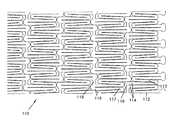
- FIG. 1is a plan view of a first embodiment of a stent according to the present invention as it would appear if it were longitudinally split and laid out flat.
- FIG. 2is the view of FIG. 1 following expansion of the stent.
- FIG. 3is a partial plan view of a tapered-strut stent according to the present invention as it would appear if it were longitudinally split and laid out flat.
- FIG. 4is a partial plan view of another embodiment of a stent according to the present invention as it would appear if it were longitudinally split and laid out flat.
- FIG. 5is a partial plan view of another embodiment of a stent according to the present invention as it would appear if it were longitudinally split and laid out flat.
- FIG. 6is an enlarged partial view of the stent of FIG. 1 .
- FIG. 7is a partial plan view of another embodiment of a stent according to the present invention, as it would appear if it were longitudinally split and laid out flat.
- FIG. 8is a plan view of another embodiment of a stent according to the present invention, as it would appear if it were longitudinally split and laid out flat.
- FIG. 9is a plan view of another embodiment of a stent according to the present invention, as it would appear if it were longitudinally split and laid out flat.
- FIG. 1illustrates a stent 10 , shown longitudinally split and laid flat, having an un-deployed or reduced circumference C r and an un-deployed length L.
- FIG. 6is an enlarged partial view of FIG. 1 to better illustrate a strut geometry as will be described.
- the stent 10is a reticulated, hollow tube.
- the stent 10may be expanded from the reduced circumference C r to an expanded or enlarged circumference C e .
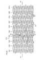
- FIG. 2is a view illustrating the expanded stent 10 as it would appear if longitudinally split and laid flat. The enlarged circumference C e is shown in FIG. 2 .
- the material of the stent 10defines a plurality of circumferential support structures 12 spaced apart along the longitudinal axis, X-X of the stent 10 .
- the phrase “circumferential support structures”will be understood to include structures that extend generally about the circumference of the stent 10 .
- the support structures 12are formed by longitudinal struts 14 .
- the struts 14have uniform cross-sectional dimensions throughout their length. Adjacent struts 14 within a support structure 12 are connected at apex portions 18 to form an undulating pattern that extends about the circumference of the stent 10 .
- apex portionis intended to mean the region where two struts 14 are joined.
- the apex portions 18can be semicircular, arcuate, pointed, square, oval, or any other shape. Adjacent support structures 12 are joined by circumferential connecting struts 16 joining apex portions 18 .
- the phrase “circumferential connecting struts” or “circumferential connecting members”will be understood to mean struts or members that interconnect adjacent circumferential support structures 12 and have a spacial component or vector that extends in a circumferential direction about the stent 12 .
- the struts 14 , apex portions 18 and connecting struts 16form bounded areas, or cells 20 , which are open as shown in FIG. 2 (i.e., extend through the wall thickness of the stent 10 ).
- the struts 14may all be the same length, or they may be of differing length. In one embodiment, when some longer struts are present, the longer struts in adjacent support structures interconnected.
- the stent 10may be formed through any suitable means including laser or chemical milling. In such processes, a hollow cylindrical tube laser cut or etched to remove material and form the open cells 20 .
- the struts 14extend along the longitudinal axis of the stent in the un-deployed orientation ( FIGS. 1 and 6 ). At least some of the apex portions 18 are configured such that, when the stent is in the un-deployed orientation, they overlap in the axial/longitudinal direction. As used herein. “overlap” is intended to mean the apex portions 18 are directly in line circumferentially or the apex portions 18 extend past each other such that the connecting strut joining them is positioned at an angle relative to the circumference. In the embodiment illustrated in FIGS.
- the overlapping apex portions 18are directly in line circumferentially, and the connecting struts 16 are substantially perpendicular to the struts 14 .
- apex portions 118 extending past each otherare joined by angled connecting struts 416 .
- the angled connecting struts 416extend at an oblique angle with respect to the circumferential direction.
- FIG. 3includes longitudinal struts 114 that are tapered, as disclosed in co-pending, commonly assigned, U.S. patent application Ser. No. 09/765,725, the entire disclosure of which is incorporated herein by reference.
- circumferential support structures 112are made up of pairs of tapered struts 114 alternating with single, non-tapered struts 113 .
- the tapered struts 114are arranged such that their wide ends 115 are adjacent circumferential connecting struts 116 and their narrow ends 117 are adjacent unconnected or free apex portions.
- the connecting struts 116can connect only apex portions 118 joining narrow ends 117 .
- one or more of the connecting strutscan have a width greater than the width of the longitudinal struts 14 .
- all connecting struts 216are wide.
- the connecting struts 216are at least 1.25, or 2, or 3, or 4, or 5, or 6, or 7 or 8 times as wide as the struts 14 .
- the connecting strutsmight range from 0.01 inch to 0.050 inches in width.
- wide connecting struts 216are positioned between some of the support structures 12
- narrower connecting struts 16are positioned between the remaining support structures 12 . Incorporating both wide connecting struts 216 and narrower connecting struts 16 in the stent can provide a customized radiopacity.
- the stent 10is advanced to a site in a lumen (e.g., an occlusion site in need of circumferential support) while in the compressed orientation.
- the stent 10is then expanded at the site.
- the stent 10may be expanded through any conventional means.
- the stent 10 in the reduced diametermay be placed at the tip of a balloon catheter.
- the stentis expanded (e.g., through expansion of the balloon) thereby causing the stent to expand from the compressed orientation to the deployed orientation.
- a preferred material for balloon expandable stentsis stainless steel.
- the stent 10may be formed of a super-elastic or shape memory material, such as nitinol, which is an alloy of nickel and titanium.
- the cells 20open to a configuration as shown in FIG. 2 .
- the expansion of the stent 10is typically provided primarily through bending of the apex portions 18 .
- the stent 10is highly flexible. To advance to a site, the axis X-X of the stent 10 bends to navigate trough a curved lumen. Further, for placement at a curved site in a lumen, the stent 10 is preferably sufficiently flexible to retain a curved shape following expansion and to bend as the lumen bends over time. The stent 10 , as described above, achieves these objections.
- the stent 10When bending on its axis X-X, the stent 10 tends to axially compress on the inside of the bend and axially expand on the outside of the bend.
- the present designpermits such axial expansion and contraction.
- the cell geometryresults in a structure that is highly flexible before and after radial expansion.
- the apex portions 18 on adjacent support structures 12are offset.
- the apex portions 18 and corresponding struts 14 on one support structure 12do not come in direct contact with facing apex portions 18 and struts 14 on an adjacent support structure 12 .
- This offset geometryprovides increased flexibility to the stent 10 and allows the stent 10 to better conform to a lumen such as a coronary vessel.
- adjacent circumferential support structures 12define waves that are “in-phase” with one another. This provides a greater longitudinal spacing (i.e., in a direction corresponding to the longitudinal axis of the stent) between the peaks as compared to having the apexes being in direct opposition to one another.
- Table 1provides examples of stent diameters and examples of offset geometry based on the number of apex portions around the circumference of the stent. It is to be understood that the dimensions in Table 1 are exemplary only and are not intended to be limiting. The dimensions are applicable to a stent in the expanded or deployed orientation. The stent dimensions will be selected based on the size and location of the lumen into which the stent is to be placed.
- This offset geometryallows for flexion of the stent without adjacent struts directly impacting each other.
- the preferred geometryhas the apexes of struts in one support structure in between the apexes of struts in the adjacent support structure. When the stent is flexed, the apexes pass by one another and do not impact, which allows for increased flexibility.
- the stent 10may be lined with either an inner or outer sleeve (such as polyester fabric or ePTFE) for tissue growth.
- the stentmay be coated with radiopaque coatings such as platinum, gold, tungsten or tantalum.
- the stentmay be formed of any one of a wide variety of previous known materials including, without limitation, MP35N, tantalum, platinum, gold, Elgiloy and Phynox.
- FIGS. 1 and 2While twenty support structures 12 are shown in FIGS. 1 and 2 connected and spaced apart along the longitudinal axis of the stent, a different number could be so connected to vary the properties of the stent 10 as a designer may elect. Likewise, while each support structure 12 in FIGS. 1 and 2 is shown as having 36 struts 14 , the number of struts 14 could vary to adjust the properties of the stent. Also, while each support structure 12 is shown connected to an adjacent support structure 12 by 6 connecting struts 16 , the number of connecting struts 16 could vary.
- the stentis made up of 20 support structures, 36 struts per support structure, 18 apex portions on each side of each support structure, and 6 connecting struts joining every third apex portion of adjacent support structures. Alternating the direction of the connecting struts between support structures prevents uneven expansion angles between the struts and prevents twisting of the stent. For example, in FIG. 1 , connecting struts 16 extend from one apex portion 18 down to another apex portion 18 between first and second support structures, and extend up between the second and third support structures. This alternating pattern of connecting struts is more pronounced in the embodiment with angled connecting struts 416 , shown in FIG. 7 .
- the stentWhen forming the stent from shape memory metal such as nitinol, the stent can be laser cut from a nitinol tube. Thereafter, the stent can be subjected to a shape-setting process in which the cut tube is expanded on a mandrel and then heated. Multiple expansion and heating cycles can be used to shape-set the stent to the final expanded diameter.
- shape memory metalsuch as nitinol
- the finished stentcan be mounted on a delivery catheter.
- the stentcan be held in a compressed orientation on the to delivery catheter by a retractable sheath.
- the delivery cathetercan be used to advance the stent to a deployment location (e.g., a constricted region of a vessel).
- the sheathis related thereby releasing the stent. Once released, the stent self-expands to the deployed diameter.
- FIG. 8shows another stent 510 that is another embodiment of the present is invention.
- the stent 510is shown in a configuration corresponding to the stent when the stent has been initially fabricated from a tube (i.e., before the stent has been compressed on a catheter). Similar to the previous embodiments, the stent is shown longitudinally split and laid flat for ease of explanation.
- the stentincludes 10 circumferential support structures CS 1 -CS 10 spaced-apart along a longitudinal axis LA of the stent 510 . Longitudinal struts 14 and apex portions 18 of the support structures CS 1 -CS 10 define an undulating pattern that extends about the circumference of the stent 510 .
- the undulating patterndefines a wave having a wavelength WL.
- Alternating pairs of the adjacent support structuresare interconnected by circumferential connecting struts 16 .
- support structure pairs CS 2 and CS 3 ; CS 4 and CS 5 ; CS 6 and CS 7 ; and CS 8 and CS 9are interconnected by circumferential connecting struts 16 .
- Struts 16 interconnecting structure CS 2 to structure CS 3 and structure CS 6 to structure CS 7extend downwardly
- struts 16 interconnecting structure CS 4 to structure CS 5 and structure CS 8 to structure CS 9extend upwardly.
- Circumferential support structures CS 1 and CS 2 ; CS 3 and CS 4 ; CS 5 and CS 6 ; CS 7 and CS 8 ; and CS 9 and CS 10are not interconnected by circumferential connecting struts. Instead, these pairs are integrally connected to one another.
- the circumferential connecting struts 16function to offset the apexes 18 of adjacent circumferential support structures relative to one another so that the apexes do not oppose one another. By offsetting the apex portions that face toward one another, the tips are prevented from contacting one another when in the expanded state thereby enhancing the stent's ability to conform to a lumen in which the stent is implanted.
- the circumferential connecting struts 16have a length equal to about one and one half (i.e., 1.5) wavelengths WL.
- the circumferential struts 16have a length of at least one half (i.e., 0.5) the wavelength WL.
- the integrally connected pairs of circumferential support structureshave apex portions 18 that oppose one another.
- FIG. 9shows a stent 610 that is another embodiment of the present invention.
- the stent 610is shown in a configuration corresponding to the stent when the stent has been initially fabricated from a tube (i.e., before the stent has been compressed on a catheter). Similar to the previous embodiments, the stent is shown longitudinally split and laid flat for ease of explanation.
- the stentincludes 10 circumferential support structures CS 1 -CS 10 spaced-apart along a longitudinal axis LA of the stent 610 . Longitudinal struts 14 and apex portions 18 of the support structures CS 1 -CS 10 define an undulating pattern that extends about the circumference of the stent 510 .
- Support structure pairs CS 2 and CS 3 ; CS 3 and CS 4 ; CS 7 and CS 8 , and CS 8 and CS 9are interconnected by circumferential connecting members 16 .
- the remaining support structure pairsi.e., pairs CS 1 and CS 2 ; CS 4 and CS 5 ; CS 5 and CS 6 ; CS 6 and CS 7 ; and CS 9 and CS 10 ) are interconnected by integrally.
- the circumferential connecting struts 16are generally perpendicularly aligned relative to the apex portions 18 . In other embodiments, the circumferential connecting struts 16 could be angled similar to the struts 416 of FIG. 7 . In embodiments where the apex portions 18 are not longitudinally overlapped, the circumferential connecting struts could be angled in the opposite direction as compared to the struts 416 of FIG. 7 .
- FIGS. 1-9illustrate a preferred use for the inventive features disclosed in FIGS. 1-9
- the featuresalso have benefits when used with non-self-expanding stents (e.g., balloon expandable stents made of a material such as stainless steel).
- FIGS. 1-9illustrate a preferred geometry for practicing the present invention
- the technique for avoiding opposing longitudinal members coming in direct contact by varying the offset positions of the struts and apex positions in a stentis also applicable to stents having other geometries, shapes, or strut patterns.
Landscapes
- Health & Medical Sciences (AREA)
- Engineering & Computer Science (AREA)
- Biomedical Technology (AREA)
- Heart & Thoracic Surgery (AREA)
- Life Sciences & Earth Sciences (AREA)
- Cardiology (AREA)
- Oral & Maxillofacial Surgery (AREA)
- Transplantation (AREA)
- Physics & Mathematics (AREA)
- Vascular Medicine (AREA)
- Optics & Photonics (AREA)
- Animal Behavior & Ethology (AREA)
- General Health & Medical Sciences (AREA)
- Public Health (AREA)
- Veterinary Medicine (AREA)
- Prostheses (AREA)
- Media Introduction/Drainage Providing Device (AREA)
Abstract
Description
| TABLE I | |||||
| Number | |||||
| of | Preferred Offset: | ||||
| I.D. | I.D. | apexes | Distance between | ½ distance between | |
| Dia- | Dia- | Circum- | around | apexes around | apexes around |
| meter | meter | ference | Circum- | Circumference | Circumference |
| (mm) | (inch) | (inch) | ference | (inch) | (inch) |
| 6.25 | 0.246 | 0.773 | 18 | 0.043 | 0.021 |
| 7.25 | 0.285 | 0.897 | 18 | 0.050 | 0.025 |
| 8.25 | 0.325 | 1.020 | 18 | 0.057 | 0.028 |
| 9.25 | 0.364 | 1.144 | 18 | 0.064 | 0.032 |
Claims (13)
Priority Applications (3)
| Application Number | Priority Date | Filing Date | Title |
|---|---|---|---|
| US11/950,931US7993388B2 (en) | 2001-09-17 | 2007-12-05 | Stent with offset cell geometry |
| US13/175,015US8876888B2 (en) | 2001-09-17 | 2011-07-01 | Stent with offset cell geometry |
| US14/501,265US9707111B2 (en) | 2001-09-17 | 2014-09-30 | Stent with offset cell geometry |
Applications Claiming Priority (2)
| Application Number | Priority Date | Filing Date | Title |
|---|---|---|---|
| US09/955,351US20030055485A1 (en) | 2001-09-17 | 2001-09-17 | Stent with offset cell geometry |
| US11/950,931US7993388B2 (en) | 2001-09-17 | 2007-12-05 | Stent with offset cell geometry |
Related Parent Applications (1)
| Application Number | Title | Priority Date | Filing Date |
|---|---|---|---|
| US09/955,351ContinuationUS20030055485A1 (en) | 2001-09-17 | 2001-09-17 | Stent with offset cell geometry |
Related Child Applications (1)
| Application Number | Title | Priority Date | Filing Date |
|---|---|---|---|
| US13/175,015ContinuationUS8876888B2 (en) | 2001-09-17 | 2011-07-01 | Stent with offset cell geometry |
Publications (2)
| Publication Number | Publication Date |
|---|---|
| US20080281404A1 US20080281404A1 (en) | 2008-11-13 |
| US7993388B2true US7993388B2 (en) | 2011-08-09 |
Family
ID=25496713
Family Applications (4)
| Application Number | Title | Priority Date | Filing Date |
|---|---|---|---|
| US09/955,351AbandonedUS20030055485A1 (en) | 2001-09-17 | 2001-09-17 | Stent with offset cell geometry |
| US11/950,931Expired - Fee RelatedUS7993388B2 (en) | 2001-09-17 | 2007-12-05 | Stent with offset cell geometry |
| US13/175,015Expired - LifetimeUS8876888B2 (en) | 2001-09-17 | 2011-07-01 | Stent with offset cell geometry |
| US14/501,265Expired - Fee RelatedUS9707111B2 (en) | 2001-09-17 | 2014-09-30 | Stent with offset cell geometry |
Family Applications Before (1)
| Application Number | Title | Priority Date | Filing Date |
|---|---|---|---|
| US09/955,351AbandonedUS20030055485A1 (en) | 2001-09-17 | 2001-09-17 | Stent with offset cell geometry |
Family Applications After (2)
| Application Number | Title | Priority Date | Filing Date |
|---|---|---|---|
| US13/175,015Expired - LifetimeUS8876888B2 (en) | 2001-09-17 | 2011-07-01 | Stent with offset cell geometry |
| US14/501,265Expired - Fee RelatedUS9707111B2 (en) | 2001-09-17 | 2014-09-30 | Stent with offset cell geometry |
Country Status (7)
| Country | Link |
|---|---|
| US (4) | US20030055485A1 (en) |
| EP (1) | EP1427352B1 (en) |
| AT (1) | ATE413853T1 (en) |
| CA (1) | CA2459914A1 (en) |
| DE (1) | DE60229859D1 (en) |
| ES (1) | ES2316623T3 (en) |
| WO (1) | WO2003024363A1 (en) |
Cited By (37)
| Publication number | Priority date | Publication date | Assignee | Title |
|---|---|---|---|---|
| US20060155355A1 (en)* | 2002-09-17 | 2006-07-13 | Johannes Jung | Stent to be implanted within or around a hollow organ |
| US20090228088A1 (en)* | 2008-03-06 | 2009-09-10 | Xtent, Inc. | Apparatus having variable strut length and methods of use |
| US20110022148A1 (en)* | 2007-02-20 | 2011-01-27 | Xtent, Inc. | Thermo-mechanically controlled implants and methods of use |
| US8177831B2 (en) | 2001-12-03 | 2012-05-15 | Xtent, Inc. | Stent delivery apparatus and method |
| US20120172971A1 (en)* | 2001-09-17 | 2012-07-05 | Ev3 Peripheral, Inc. | Stent with offset cell geometry |
| US8282680B2 (en) | 2003-01-17 | 2012-10-09 | J. W. Medical Systems Ltd. | Multiple independent nested stent structures and methods for their preparation and deployment |
| US8317859B2 (en) | 2004-06-28 | 2012-11-27 | J.W. Medical Systems Ltd. | Devices and methods for controlling expandable prostheses during deployment |
| US8460358B2 (en) | 2004-03-30 | 2013-06-11 | J.W. Medical Systems, Ltd. | Rapid exchange interventional devices and methods |
| US8486132B2 (en) | 2007-03-22 | 2013-07-16 | J.W. Medical Systems Ltd. | Devices and methods for controlling expandable prostheses during deployment |
| US20130226283A1 (en)* | 2011-11-15 | 2013-08-29 | Abbott Cardiovascular Systems Inc. | Offset peak-to-peak stent pattern |
| US8574282B2 (en) | 2001-12-03 | 2013-11-05 | J.W. Medical Systems Ltd. | Apparatus and methods for delivery of braided prostheses |
| US8585747B2 (en) | 2003-12-23 | 2013-11-19 | J.W. Medical Systems Ltd. | Devices and methods for controlling and indicating the length of an interventional element |
| WO2014018837A1 (en) | 2012-07-26 | 2014-01-30 | Cheng Cecilia | Butanol purification |
| US8652198B2 (en) | 2006-03-20 | 2014-02-18 | J.W. Medical Systems Ltd. | Apparatus and methods for deployment of linked prosthetic segments |
| WO2014047412A1 (en) | 2012-09-21 | 2014-03-27 | Butamax(Tm) Advanced Biofuels Llc | A method for producing butanol using two-phase extractive fermentation and recyclable extractant compositions |
| US8702781B2 (en) | 2001-12-03 | 2014-04-22 | J.W. Medical Systems Ltd. | Apparatus and methods for delivery of multiple distributed stents |
| WO2014081848A1 (en) | 2012-11-20 | 2014-05-30 | Butamax Advanced Biofuels Llc | Butanol purification |
| WO2014130352A1 (en) | 2013-02-21 | 2014-08-28 | Butamax Advanced Biofuels Llc | Recovery of thermal energy as heat source in the production of butanol from a fermentation process |
| WO2014144728A1 (en) | 2013-03-15 | 2014-09-18 | Butamax Advanced Biofuels Llc | Method for production of butanol using extractive fermentation |
| WO2014144643A1 (en) | 2013-03-15 | 2014-09-18 | Butamax Advanced Biofuels Llc | Method for producing butanol using extractive fermentation |
| WO2014151645A1 (en) | 2013-03-15 | 2014-09-25 | Butamax Advanced Biofuels Llc | Process for maximizing biomass growth and butanol yield by feedback control |
| WO2014160050A1 (en) | 2013-03-14 | 2014-10-02 | Butamax Advanced Biofuels Llc | Glycerol 3- phosphate dehydrogenase for butanol production |
| US8956398B2 (en) | 2001-12-03 | 2015-02-17 | J.W. Medical Systems Ltd. | Custom length stent apparatus |
| USD723165S1 (en) | 2013-03-12 | 2015-02-24 | C. R. Bard, Inc. | Stent |
| US8986362B2 (en) | 2004-06-28 | 2015-03-24 | J.W. Medical Systems Ltd. | Devices and methods for controlling expandable prostheses during deployment |
| WO2015065871A1 (en) | 2013-10-28 | 2015-05-07 | Danisco Us Inc. | Large scale genetically engineered active dry yeast |
| US9066825B2 (en) | 2012-05-14 | 2015-06-30 | C.R. Bard, Inc. | Uniformly expandable stent |
| US9180031B2 (en) | 2013-03-15 | 2015-11-10 | Covidien Lp | Stent with varying radius between struts |
| US9259335B2 (en) | 2013-03-15 | 2016-02-16 | Covidien Lp | Stent |
| US20170014249A1 (en)* | 2006-02-14 | 2017-01-19 | Angiomed Gmbh & Co. Medizintechnik Kg | Highly flexible stent and method of manufacture |
| US9663759B2 (en) | 2013-07-03 | 2017-05-30 | Butamax Advanced Biofuels Llc | Partial adaptation for butanol production |
| US10258488B2 (en) | 2016-11-14 | 2019-04-16 | Covidien Lp | Stent |
| US10449069B2 (en) | 2016-11-14 | 2019-10-22 | Covidien Lp | Stent |
| US10617517B2 (en) | 2013-01-14 | 2020-04-14 | Medtronic CV Luxembourg S.a.r.l. | Valve prosthesis frames |
| US10905572B2 (en) | 2016-11-14 | 2021-02-02 | Covidien Lp | Stent |
| US11399969B2 (en) | 2014-04-18 | 2022-08-02 | Covidien Lp | Stent delivery system |
| WO2023015144A1 (en)* | 2021-08-02 | 2023-02-09 | Merit Medical Systems, Inc. | Coronary covered stent |
Families Citing this family (44)
| Publication number | Priority date | Publication date | Assignee | Title |
|---|---|---|---|---|
| GB0020491D0 (en) | 2000-08-18 | 2000-10-11 | Angiomed Ag | Stent with attached element and method of making such a stent |
| US9561123B2 (en) | 2002-08-30 | 2017-02-07 | C.R. Bard, Inc. | Highly flexible stent and method of manufacture |
| US6878162B2 (en)* | 2002-08-30 | 2005-04-12 | Edwards Lifesciences Ag | Helical stent having improved flexibility and expandability |
| US8105373B2 (en)* | 2002-12-16 | 2012-01-31 | Boston Scientific Scimed, Inc. | Flexible stent with improved axial strength |
| JP4591348B2 (en)* | 2003-04-30 | 2010-12-01 | ニプロ株式会社 | Flexible stent with excellent blood vessel followability and good expandability |
| RU2342104C2 (en)* | 2003-04-30 | 2008-12-27 | Нипро Корпорейшн | Extending flexible stent designed for introduction in blood vessels |
| WO2006001367A1 (en)* | 2004-06-25 | 2006-01-05 | Zeon Corporation | Stent |
| US20060074480A1 (en) | 2004-09-01 | 2006-04-06 | Pst, Llc | Stent and method for manufacturing the stent |
| US20060060266A1 (en)* | 2004-09-01 | 2006-03-23 | Pst, Llc | Stent and method for manufacturing the stent |
| WO2006063222A1 (en)* | 2004-12-09 | 2006-06-15 | Med Institute, Inc. | Variable curvature stent |
| US8435280B2 (en)* | 2005-03-31 | 2013-05-07 | Boston Scientific Scimed, Inc. | Flexible stent with variable width elements |
| GB0609841D0 (en) | 2006-05-17 | 2006-06-28 | Angiomed Ag | Bend-capable tubular prosthesis |
| GB0609911D0 (en)* | 2006-05-18 | 2006-06-28 | Angiomed Ag | Bend-capable stent prosthesis |
| GB0616579D0 (en)* | 2006-08-21 | 2006-09-27 | Angiomed Ag | Self-expanding stent |
| GB0616999D0 (en)* | 2006-08-29 | 2006-10-04 | Angiomed Ag | Annular mesh |
| EP2063824B1 (en)* | 2006-09-07 | 2020-10-28 | Angiomed GmbH & Co. Medizintechnik KG | Helical implant having different ends |
| GB0622465D0 (en) | 2006-11-10 | 2006-12-20 | Angiomed Ag | Stent |
| GB0624419D0 (en)* | 2006-12-06 | 2007-01-17 | Angiomed Ag | Stenting ring with marker |
| WO2008100780A2 (en) | 2007-02-12 | 2008-08-21 | C.R.Bard Inc. | Highly flexible stent and method of manufacture |
| US8333799B2 (en) | 2007-02-12 | 2012-12-18 | C. R. Bard, Inc. | Highly flexible stent and method of manufacture |
| EP4005537A1 (en) | 2007-02-12 | 2022-06-01 | C.R. Bard Inc. | Highly flexible stent and method of manufacture |
| US8512392B2 (en)* | 2007-03-09 | 2013-08-20 | Boston Scientific Scimed, Inc. | Stent design with struts of various angles and stiffness |
| GB0706499D0 (en) | 2007-04-03 | 2007-05-09 | Angiomed Ag | Bendable stent |
| US8303644B2 (en)* | 2007-05-04 | 2012-11-06 | Abbott Cardiovascular Systems Inc. | Stents with high radial strength and methods of manufacturing same |
| US8211162B2 (en)* | 2007-05-25 | 2012-07-03 | Boston Scientific Scimed, Inc. | Connector node for durable stent |
| GB0717481D0 (en) | 2007-09-07 | 2007-10-17 | Angiomed Ag | Self-expansible stent with radiopaque markers |
| EP2266508A1 (en)* | 2009-06-25 | 2010-12-29 | Biotronik VI Patent AG | Stent with improved stent design |
| US8114149B2 (en)* | 2009-10-20 | 2012-02-14 | Svelte Medical Systems, Inc. | Hybrid stent with helical connectors |
| BR112012011466B1 (en)* | 2009-10-30 | 2020-10-27 | Cordis Corporation | stent for insertion into a patient's vessel |
| JP2014508559A (en) | 2010-12-30 | 2014-04-10 | ボストン サイエンティフィック サイムド,インコーポレイテッド | Multi-stage open stent design |
| WO2012119037A1 (en) | 2011-03-03 | 2012-09-07 | Boston Scientific Scimed, Inc. | Stent with reduced profile |
| EP2680797B1 (en) | 2011-03-03 | 2016-10-26 | Boston Scientific Scimed, Inc. | Low strain high strength stent |
| US9566633B2 (en)* | 2012-11-15 | 2017-02-14 | Vactronix Scientific, Inc. | Stents having a hybrid pattern and methods of manufacture |
| USD888245S1 (en)* | 2014-03-14 | 2020-06-23 | Vactronix Scientific, Llc | Stent device |
| US10117763B2 (en) | 2014-03-18 | 2018-11-06 | Boston Scientific Scimed, Inc. | Reduced granulation and inflammation stent design |
| WO2016110875A1 (en)* | 2015-01-07 | 2016-07-14 | Sahajanand Medical Technologies Private Limited | Endoluminal stent |
| US11622872B2 (en)* | 2016-05-16 | 2023-04-11 | Elixir Medical Corporation | Uncaging stent |
| CN106859821B (en)* | 2017-03-15 | 2018-06-15 | 大连理工大学 | A kind of biodegradable polymer intravascular stent of injection molding |
| US10500078B2 (en) | 2018-03-09 | 2019-12-10 | Vesper Medical, Inc. | Implantable stent |
| USD881396S1 (en)* | 2018-08-14 | 2020-04-14 | Beijing Med-Zenith, Medical Scientific Co., Ltd. | Pulmonary artery stent |
| USD885577S1 (en)* | 2018-11-13 | 2020-05-26 | Transit Scientific, LLC | Expandable medical device |
| USD885576S1 (en)* | 2018-11-13 | 2020-05-26 | Transit Scientific, LLC | Expandable medical device |
| US11058564B2 (en)* | 2019-02-27 | 2021-07-13 | Vactronix Scientific Llc | Stent and method of making same |
| EP4093327A1 (en)* | 2020-01-21 | 2022-11-30 | W.L. Gore & Associates, Inc. | Endoprostheses with interlocking stents having varying stiffness |
Citations (20)
| Publication number | Priority date | Publication date | Assignee | Title |
|---|---|---|---|---|
| US5449373A (en) | 1994-03-17 | 1995-09-12 | Medinol Ltd. | Articulated stent |
| WO1995031945A1 (en) | 1994-05-19 | 1995-11-30 | Scimed Life Systems, Inc. | Improved tissue supporting devices |
| US5514154A (en) | 1991-10-28 | 1996-05-07 | Advanced Cardiovascular Systems, Inc. | Expandable stents |
| WO1996026689A1 (en) | 1995-03-01 | 1996-09-06 | Scimed Life Systems, Inc. | Improved longitudinally flexible expandable stent |
| WO1997040783A2 (en) | 1996-04-26 | 1997-11-06 | Jang G David | Intravascular stent |
| WO1998040035A1 (en) | 1997-03-13 | 1998-09-17 | United States Surgical Corporation | Flexible tissue supporting device |
| US5824059A (en) | 1997-08-05 | 1998-10-20 | Wijay; Bandula | Flexible stent |
| EP0928605A2 (en) | 1998-01-09 | 1999-07-14 | Nitinol Development Corporation | An intravascular stent having an improved strut configuration |
| US6033433A (en) | 1997-04-25 | 2000-03-07 | Scimed Life Systems, Inc. | Stent configurations including spirals |
| US6132461A (en) | 1998-03-27 | 2000-10-17 | Intratherapeutics, Inc. | Stent with dual support structure |
| US6132460A (en) | 1998-03-27 | 2000-10-17 | Intratherapeutics, Inc. | Stent |
| WO2001001888A1 (en) | 1999-07-02 | 2001-01-11 | Scimed Life Systems, Inc. | Flexible segmented stents |
| US6190406B1 (en) | 1998-01-09 | 2001-02-20 | Nitinal Development Corporation | Intravascular stent having tapered struts |
| US6241760B1 (en) | 1996-04-26 | 2001-06-05 | G. David Jang | Intravascular stent |
| US20010047199A1 (en) | 1998-12-08 | 2001-11-29 | Bandula Wijay | Stent with nested or overlapping rings |
| EP1159934A2 (en) | 2000-06-01 | 2001-12-05 | Terumo Kabushiki Kaisha | Implantable tubular device (stent) |
| US20020156524A1 (en) | 1998-09-10 | 2002-10-24 | Scimed Life Systems, Inc. | Stent configurations |
| US20030167084A1 (en) | 1999-05-19 | 2003-09-04 | Michael Orlowski | Radially expandable vascular stent |
| US6776793B2 (en) | 1995-03-01 | 2004-08-17 | Scimed Life Systems, Inc. | Longitudinally flexible expandable stent |
| EP1049421B1 (en) | 1998-11-20 | 2005-01-26 | Boston Scientific Limited | Longitudinally flexible expandable stent |
Family Cites Families (4)
| Publication number | Priority date | Publication date | Assignee | Title |
|---|---|---|---|---|
| JP4292710B2 (en)* | 1997-09-24 | 2009-07-08 | エム イー ディ インスチィチュート インク | Radially expandable stent |
| US6264687B1 (en)* | 1998-04-20 | 2001-07-24 | Cordis Corporation | Multi-laminate stent having superelastic articulated sections |
| US6652579B1 (en)* | 2000-06-22 | 2003-11-25 | Advanced Cardiovascular Systems, Inc. | Radiopaque stent |
| US20030055485A1 (en) | 2001-09-17 | 2003-03-20 | Intra Therapeutics, Inc. | Stent with offset cell geometry |
- 2001
- 2001-09-17USUS09/955,351patent/US20030055485A1/ennot_activeAbandoned
- 2002
- 2002-09-16DEDE60229859Tpatent/DE60229859D1/ennot_activeExpired - Lifetime
- 2002-09-16CACA002459914Apatent/CA2459914A1/ennot_activeAbandoned
- 2002-09-16ATAT02775839Tpatent/ATE413853T1/ennot_activeIP Right Cessation
- 2002-09-16WOPCT/US2002/029483patent/WO2003024363A1/ennot_activeApplication Discontinuation
- 2002-09-16ESES02775839Tpatent/ES2316623T3/ennot_activeExpired - Lifetime
- 2002-09-16EPEP02775839Apatent/EP1427352B1/ennot_activeExpired - Lifetime
- 2007
- 2007-12-05USUS11/950,931patent/US7993388B2/ennot_activeExpired - Fee Related
- 2011
- 2011-07-01USUS13/175,015patent/US8876888B2/ennot_activeExpired - Lifetime
- 2014
- 2014-09-30USUS14/501,265patent/US9707111B2/ennot_activeExpired - Fee Related
Patent Citations (24)
| Publication number | Priority date | Publication date | Assignee | Title |
|---|---|---|---|---|
| US6066167A (en) | 1991-10-28 | 2000-05-23 | Advanced Cardiovascular Systems, Inc. | Expandable stents |
| US5514154A (en) | 1991-10-28 | 1996-05-07 | Advanced Cardiovascular Systems, Inc. | Expandable stents |
| US5449373A (en) | 1994-03-17 | 1995-09-12 | Medinol Ltd. | Articulated stent |
| WO1995031945A1 (en) | 1994-05-19 | 1995-11-30 | Scimed Life Systems, Inc. | Improved tissue supporting devices |
| WO1996026689A1 (en) | 1995-03-01 | 1996-09-06 | Scimed Life Systems, Inc. | Improved longitudinally flexible expandable stent |
| US6776793B2 (en) | 1995-03-01 | 2004-08-17 | Scimed Life Systems, Inc. | Longitudinally flexible expandable stent |
| WO1997040783A2 (en) | 1996-04-26 | 1997-11-06 | Jang G David | Intravascular stent |
| US6241760B1 (en) | 1996-04-26 | 2001-06-05 | G. David Jang | Intravascular stent |
| WO1998040035A1 (en) | 1997-03-13 | 1998-09-17 | United States Surgical Corporation | Flexible tissue supporting device |
| US6033433A (en) | 1997-04-25 | 2000-03-07 | Scimed Life Systems, Inc. | Stent configurations including spirals |
| US5824059A (en) | 1997-08-05 | 1998-10-20 | Wijay; Bandula | Flexible stent |
| US6129755A (en) | 1998-01-09 | 2000-10-10 | Nitinol Development Corporation | Intravascular stent having an improved strut configuration |
| EP0928605A3 (en) | 1998-01-09 | 2000-03-22 | Nitinol Development Corporation | An intravascular stent having an improved strut configuration |
| EP0928605A2 (en) | 1998-01-09 | 1999-07-14 | Nitinol Development Corporation | An intravascular stent having an improved strut configuration |
| US6190406B1 (en) | 1998-01-09 | 2001-02-20 | Nitinal Development Corporation | Intravascular stent having tapered struts |
| US6132461A (en) | 1998-03-27 | 2000-10-17 | Intratherapeutics, Inc. | Stent with dual support structure |
| US6132460A (en) | 1998-03-27 | 2000-10-17 | Intratherapeutics, Inc. | Stent |
| US20020156524A1 (en) | 1998-09-10 | 2002-10-24 | Scimed Life Systems, Inc. | Stent configurations |
| EP1049421B1 (en) | 1998-11-20 | 2005-01-26 | Boston Scientific Limited | Longitudinally flexible expandable stent |
| US20010047199A1 (en) | 1998-12-08 | 2001-11-29 | Bandula Wijay | Stent with nested or overlapping rings |
| US6340366B2 (en)* | 1998-12-08 | 2002-01-22 | Bandula Wijay | Stent with nested or overlapping rings |
| US20030167084A1 (en) | 1999-05-19 | 2003-09-04 | Michael Orlowski | Radially expandable vascular stent |
| WO2001001888A1 (en) | 1999-07-02 | 2001-01-11 | Scimed Life Systems, Inc. | Flexible segmented stents |
| EP1159934A2 (en) | 2000-06-01 | 2001-12-05 | Terumo Kabushiki Kaisha | Implantable tubular device (stent) |
Cited By (58)
| Publication number | Priority date | Publication date | Assignee | Title |
|---|---|---|---|---|
| US20120172971A1 (en)* | 2001-09-17 | 2012-07-05 | Ev3 Peripheral, Inc. | Stent with offset cell geometry |
| US8876888B2 (en)* | 2001-09-17 | 2014-11-04 | Covidien Lp | Stent with offset cell geometry |
| US9707111B2 (en) | 2001-09-17 | 2017-07-18 | Covidien Lp | Stent with offset cell geometry |
| US8702781B2 (en) | 2001-12-03 | 2014-04-22 | J.W. Medical Systems Ltd. | Apparatus and methods for delivery of multiple distributed stents |
| US8177831B2 (en) | 2001-12-03 | 2012-05-15 | Xtent, Inc. | Stent delivery apparatus and method |
| US8956398B2 (en) | 2001-12-03 | 2015-02-17 | J.W. Medical Systems Ltd. | Custom length stent apparatus |
| US9326876B2 (en) | 2001-12-03 | 2016-05-03 | J.W. Medical Systems Ltd. | Apparatus and methods for delivery of multiple distributed stents |
| US8574282B2 (en) | 2001-12-03 | 2013-11-05 | J.W. Medical Systems Ltd. | Apparatus and methods for delivery of braided prostheses |
| US20060155355A1 (en)* | 2002-09-17 | 2006-07-13 | Johannes Jung | Stent to be implanted within or around a hollow organ |
| US9675479B2 (en)* | 2002-09-17 | 2017-06-13 | Pfm Medical Ag | Stent to be implanted within or around a hollow organ |
| US8740968B2 (en) | 2003-01-17 | 2014-06-03 | J.W. Medical Systems Ltd. | Multiple independent nested stent structures and methods for their preparation and deployment |
| US8282680B2 (en) | 2003-01-17 | 2012-10-09 | J. W. Medical Systems Ltd. | Multiple independent nested stent structures and methods for their preparation and deployment |
| US8585747B2 (en) | 2003-12-23 | 2013-11-19 | J.W. Medical Systems Ltd. | Devices and methods for controlling and indicating the length of an interventional element |
| US9566179B2 (en) | 2003-12-23 | 2017-02-14 | J.W. Medical Systems Ltd. | Devices and methods for controlling and indicating the length of an interventional element |
| US8460358B2 (en) | 2004-03-30 | 2013-06-11 | J.W. Medical Systems, Ltd. | Rapid exchange interventional devices and methods |
| US9700448B2 (en) | 2004-06-28 | 2017-07-11 | J.W. Medical Systems Ltd. | Devices and methods for controlling expandable prostheses during deployment |
| US8317859B2 (en) | 2004-06-28 | 2012-11-27 | J.W. Medical Systems Ltd. | Devices and methods for controlling expandable prostheses during deployment |
| US8986362B2 (en) | 2004-06-28 | 2015-03-24 | J.W. Medical Systems Ltd. | Devices and methods for controlling expandable prostheses during deployment |
| US20170014249A1 (en)* | 2006-02-14 | 2017-01-19 | Angiomed Gmbh & Co. Medizintechnik Kg | Highly flexible stent and method of manufacture |
| US10390978B2 (en)* | 2006-02-14 | 2019-08-27 | Angiomed Gmbh & Co. Medizintechnik Kg | Highly flexible stent and method of manufacture |
| US9883957B2 (en) | 2006-03-20 | 2018-02-06 | J.W. Medical Systems Ltd. | Apparatus and methods for deployment of linked prosthetic segments |
| US8652198B2 (en) | 2006-03-20 | 2014-02-18 | J.W. Medical Systems Ltd. | Apparatus and methods for deployment of linked prosthetic segments |
| US20110022148A1 (en)* | 2007-02-20 | 2011-01-27 | Xtent, Inc. | Thermo-mechanically controlled implants and methods of use |
| US8980297B2 (en) | 2007-02-20 | 2015-03-17 | J.W. Medical Systems Ltd. | Thermo-mechanically controlled implants and methods of use |
| US9457133B2 (en) | 2007-02-20 | 2016-10-04 | J.W. Medical Systems Ltd. | Thermo-mechanically controlled implants and methods of use |
| US9339404B2 (en) | 2007-03-22 | 2016-05-17 | J.W. Medical Systems Ltd. | Devices and methods for controlling expandable prostheses during deployment |
| US8486132B2 (en) | 2007-03-22 | 2013-07-16 | J.W. Medical Systems Ltd. | Devices and methods for controlling expandable prostheses during deployment |
| US20090228088A1 (en)* | 2008-03-06 | 2009-09-10 | Xtent, Inc. | Apparatus having variable strut length and methods of use |
| US9101503B2 (en)* | 2008-03-06 | 2015-08-11 | J.W. Medical Systems Ltd. | Apparatus having variable strut length and methods of use |
| US20130226283A1 (en)* | 2011-11-15 | 2013-08-29 | Abbott Cardiovascular Systems Inc. | Offset peak-to-peak stent pattern |
| US10588765B2 (en) | 2012-05-14 | 2020-03-17 | C. R. Bard, Inc. | Uniformly expandable stent |
| US9066825B2 (en) | 2012-05-14 | 2015-06-30 | C.R. Bard, Inc. | Uniformly expandable stent |
| WO2014018837A1 (en) | 2012-07-26 | 2014-01-30 | Cheng Cecilia | Butanol purification |
| WO2014047412A1 (en) | 2012-09-21 | 2014-03-27 | Butamax(Tm) Advanced Biofuels Llc | A method for producing butanol using two-phase extractive fermentation and recyclable extractant compositions |
| WO2014081848A1 (en) | 2012-11-20 | 2014-05-30 | Butamax Advanced Biofuels Llc | Butanol purification |
| US11911269B2 (en) | 2013-01-14 | 2024-02-27 | Medtronic CV Luxembourg S.a.r.l. | Valve prosthesis frames |
| US11298226B2 (en) | 2013-01-14 | 2022-04-12 | Medtronic CV Luxembourg S.a.r.l. | Valve prosthesis frames |
| US10617517B2 (en) | 2013-01-14 | 2020-04-14 | Medtronic CV Luxembourg S.a.r.l. | Valve prosthesis frames |
| WO2014130352A1 (en) | 2013-02-21 | 2014-08-28 | Butamax Advanced Biofuels Llc | Recovery of thermal energy as heat source in the production of butanol from a fermentation process |
| USD723165S1 (en) | 2013-03-12 | 2015-02-24 | C. R. Bard, Inc. | Stent |
| WO2014160050A1 (en) | 2013-03-14 | 2014-10-02 | Butamax Advanced Biofuels Llc | Glycerol 3- phosphate dehydrogenase for butanol production |
| US10772748B2 (en) | 2013-03-15 | 2020-09-15 | Covidien Lp | Stent |
| US9180031B2 (en) | 2013-03-15 | 2015-11-10 | Covidien Lp | Stent with varying radius between struts |
| US9943425B2 (en) | 2013-03-15 | 2018-04-17 | Covidien Lp | Stent |
| US10022253B2 (en) | 2013-03-15 | 2018-07-17 | Covidien Lp | Stent with varying radius of curvature between struts |
| US9259335B2 (en) | 2013-03-15 | 2016-02-16 | Covidien Lp | Stent |
| WO2014144728A1 (en) | 2013-03-15 | 2014-09-18 | Butamax Advanced Biofuels Llc | Method for production of butanol using extractive fermentation |
| WO2014144643A1 (en) | 2013-03-15 | 2014-09-18 | Butamax Advanced Biofuels Llc | Method for producing butanol using extractive fermentation |
| US11364135B2 (en) | 2013-03-15 | 2022-06-21 | Covidien Lp | Stent |
| WO2014151645A1 (en) | 2013-03-15 | 2014-09-25 | Butamax Advanced Biofuels Llc | Process for maximizing biomass growth and butanol yield by feedback control |
| US10308910B2 (en) | 2013-07-03 | 2019-06-04 | Butamax Advanced Biofuels Llc | Partial adaption for butanol production |
| US9663759B2 (en) | 2013-07-03 | 2017-05-30 | Butamax Advanced Biofuels Llc | Partial adaptation for butanol production |
| WO2015065871A1 (en) | 2013-10-28 | 2015-05-07 | Danisco Us Inc. | Large scale genetically engineered active dry yeast |
| US11399969B2 (en) | 2014-04-18 | 2022-08-02 | Covidien Lp | Stent delivery system |
| US10905572B2 (en) | 2016-11-14 | 2021-02-02 | Covidien Lp | Stent |
| US10449069B2 (en) | 2016-11-14 | 2019-10-22 | Covidien Lp | Stent |
| US10258488B2 (en) | 2016-11-14 | 2019-04-16 | Covidien Lp | Stent |
| WO2023015144A1 (en)* | 2021-08-02 | 2023-02-09 | Merit Medical Systems, Inc. | Coronary covered stent |
Also Published As
| Publication number | Publication date |
|---|---|
| US20080281404A1 (en) | 2008-11-13 |
| CA2459914A1 (en) | 2003-03-27 |
| WO2003024363A1 (en) | 2003-03-27 |
| EP1427352B1 (en) | 2008-11-12 |
| US9707111B2 (en) | 2017-07-18 |
| DE60229859D1 (en) | 2008-12-24 |
| US20150105853A1 (en) | 2015-04-16 |
| ATE413853T1 (en) | 2008-11-15 |
| ES2316623T3 (en) | 2009-04-16 |
| US8876888B2 (en) | 2014-11-04 |
| EP1427352A1 (en) | 2004-06-16 |
| US20030055485A1 (en) | 2003-03-20 |
| US20120172971A1 (en) | 2012-07-05 |
Similar Documents
| Publication | Publication Date | Title |
|---|---|---|
| US7993388B2 (en) | Stent with offset cell geometry | |
| US9034029B2 (en) | Stents with tapered struts | |
| US8075610B2 (en) | Endoprosthesis for controlled contraction and expansion | |
| US7128756B2 (en) | Endoprosthesis having foot extensions | |
| EP1242005B1 (en) | Stent designs for use in peripheral vessels | |
| US7625398B2 (en) | Endoprosthesis having foot extensions | |
| US7887578B2 (en) | Stent having an expandable web structure | |
| EP3057540B1 (en) | Vascular stent | |
| KR20010035531A (en) | Longitudinally flexible stent |
Legal Events
| Date | Code | Title | Description |
|---|---|---|---|
| AS | Assignment | Owner name:INTRATHERAPEUTICS, INC., MINNESOTA Free format text:ASSIGNMENT OF ASSIGNORS INTEREST;ASSIGNORS:LEE, NATHAN T;THOMPSON, PAUL J.;REEL/FRAME:020220/0363 Effective date:20010914 Owner name:SULZER INTRATHERAPEUTICS, INC., MINNESOTA Free format text:CHANGE OF NAME;ASSIGNOR:INTRATHERAPEUTICS, INC.;REEL/FRAME:020260/0783 Effective date:20010201 Owner name:EV3 PERIPHERAL, INC., MINNESOTA Free format text:CHANGE OF NAME;ASSIGNOR:SULZER INTRATHERAPEUTICS, INC.;REEL/FRAME:020220/0576 Effective date:20021227 | |
| STCF | Information on status: patent grant | Free format text:PATENTED CASE | |
| AS | Assignment | Owner name:TYCO HEALTHCARE GROUP LP, MASSACHUSETTS Free format text:ASSIGNMENT OF ASSIGNORS INTEREST;ASSIGNOR:EV3 LLC;REEL/FRAME:033748/0216 Effective date:20101223 Owner name:COVIDIEN LP, MASSACHUSETTS Free format text:CHANGE OF NAME;ASSIGNOR:TYCO HEALTHCARE GROUP LP;REEL/FRAME:033753/0578 Effective date:20120928 Owner name:EV3 INC., MINNESOTA Free format text:MERGER;ASSIGNOR:EV3 PERIPHERAL, INC.;REEL/FRAME:033748/0111 Effective date:20101220 Owner name:EV3 LLC, MINNESOTA Free format text:CHANGE OF NAME;ASSIGNOR:EV3 INC.;REEL/FRAME:033753/0565 Effective date:20101222 | |
| FPAY | Fee payment | Year of fee payment:4 | |
| MAFP | Maintenance fee payment | Free format text:PAYMENT OF MAINTENANCE FEE, 8TH YEAR, LARGE ENTITY (ORIGINAL EVENT CODE: M1552); ENTITY STATUS OF PATENT OWNER: LARGE ENTITY Year of fee payment:8 | |
| FEPP | Fee payment procedure | Free format text:MAINTENANCE FEE REMINDER MAILED (ORIGINAL EVENT CODE: REM.); ENTITY STATUS OF PATENT OWNER: LARGE ENTITY | |
| LAPS | Lapse for failure to pay maintenance fees | Free format text:PATENT EXPIRED FOR FAILURE TO PAY MAINTENANCE FEES (ORIGINAL EVENT CODE: EXP.); ENTITY STATUS OF PATENT OWNER: LARGE ENTITY | |
| STCH | Information on status: patent discontinuation | Free format text:PATENT EXPIRED DUE TO NONPAYMENT OF MAINTENANCE FEES UNDER 37 CFR 1.362 | |
| FP | Lapsed due to failure to pay maintenance fee | Effective date:20230809 |