US7993366B2 - Self-tensioning vascular occlusion device and method for its use - Google Patents
Self-tensioning vascular occlusion device and method for its useDownload PDFInfo
- Publication number
- US7993366B2 US7993366B2US10/974,008US97400804AUS7993366B2US 7993366 B2US7993366 B2US 7993366B2US 97400804 AUS97400804 AUS 97400804AUS 7993366 B2US7993366 B2US 7993366B2
- Authority
- US
- United States
- Prior art keywords
- sheath
- dilator
- catheter
- tensioning
- expansible
- Prior art date
- Legal status (The legal status is an assumption and is not a legal conclusion. Google has not performed a legal analysis and makes no representation as to the accuracy of the status listed.)
- Expired - Lifetime, expires
Links
Images


Classifications
- A—HUMAN NECESSITIES
- A61—MEDICAL OR VETERINARY SCIENCE; HYGIENE
- A61B—DIAGNOSIS; SURGERY; IDENTIFICATION
- A61B17/00—Surgical instruments, devices or methods
- A61B17/0057—Implements for plugging an opening in the wall of a hollow or tubular organ, e.g. for sealing a vessel puncture or closing a cardiac septal defect
- A61B2017/00646—Type of implements
- A61B2017/00659—Type of implements located only on one side of the opening
- A—HUMAN NECESSITIES
- A61—MEDICAL OR VETERINARY SCIENCE; HYGIENE
- A61B—DIAGNOSIS; SURGERY; IDENTIFICATION
- A61B17/00—Surgical instruments, devices or methods
- A61B2017/00982—General structural features
- A61B2017/00986—Malecots, e.g. slotted tubes, of which the distal end is pulled to deflect side struts
- A—HUMAN NECESSITIES
- A61—MEDICAL OR VETERINARY SCIENCE; HYGIENE
- A61B—DIAGNOSIS; SURGERY; IDENTIFICATION
- A61B90/00—Instruments, implements or accessories specially adapted for surgery or diagnosis and not covered by any of the groups A61B1/00 - A61B50/00, e.g. for luxation treatment or for protecting wound edges
- A61B90/08—Accessories or related features not otherwise provided for
- A61B2090/0807—Indication means
Definitions
- the present inventionrelates generally to devices, systems, and methods for percutaneous sealing of puncture sites in body lumens or tissue tracts. More specifically, the present invention relates to self-tensioning vascular occlusion devices, systems, and methods for its use for hemostasis of vascular puncture sites.
- Percutaneous access of blood vessels in the human bodyis routinely performed for diagnostics or interventional procedures such as coronary and peripheral angiography, angioplasty, atherectomies, placement of vascular stents, coronary retroperfusion and retroinfusion, cerebral angiograms, treatment of strokes, cerebral aneurysms, and the like.
- diagnostics or interventional proceduressuch as coronary and peripheral angiography, angioplasty, atherectomies, placement of vascular stents, coronary retroperfusion and retroinfusion, cerebral angiograms, treatment of strokes, cerebral aneurysms, and the like.
- Patients undergoing these proceduresare often treated with anti-coagulants such as heparin, thrombolytics, and the like, which make the closure and hemostasis process of the puncture site in the vessel wall at the completion of such catheterization procedures more difficult to achieve.
- Such devicestypically provide hemostasis by sealing the puncture site from the inside of the vessel wall wherein the device is left in place in the vessel lumen until hemostasis is reached and thereafter removed.
- These devicesgenerally comprises two separate and distinct components, namely a catheter and an external tensioning element.
- the external tensioning elementis typically connected to the catheter shaft and rests on an exterior surface of the skin after the catheter is positioned in the vessel. It provides tension to the catheter at the puncture site as well as anchors the applied tension so that a tip of the deployed catheter is maintained against the vessel wall at the puncture site.
- the external tensioning elementis kept in tension for a period of time.
- the external tensioning elementis not always easy and convenient in its application. Further, the external tensioning element may not always preserve the integrity of the catheter system. For example, manipulation of the catheter when the external tensioner is applied or removed may cause disruption of the seal at the vessel puncture site, resulting in bleeding or hematoma formation (i.e., leaking of blood into interstitial space). Also, the external tensioner may be subject to being dislodged accidentally while in use, which may result in complications, such as resumption of bleeding.
- the present inventionadvantageously provides self-tensioning occlusion devices, systems, and methods for percutaneous access and closure of puncture sites in a body lumen, particularly blood vessels of the human body. It will be appreciated however that application of the present invention is not limited to the blood vasculature, and as such may be applied to any of the vessels, even severely tortuous vessels, ducts, and cavities found in the body as well as tissue tracts. Such closure devices, systems, and methods utilize the body's own natural healing mechanism to achieve complete hemostasis without leaving any foreign objects behind.
- a device for hemostasis of a puncture site in a body lumen or tissue tractcomprises a catheter body having a proximal end and a distal end, an occlusion member, and a tensioning member.
- the occlusion membersuch as an expansible member, is disposed on a distal end of the body.
- the tensioning memberis slidably disposed over the body and proximal the expansion member.
- the tensioning memberwill be positionable against subcutaneous tissue so as to lodge and anchor the expansible member against the puncture site.
- the expansible memberallows for sealing of the puncture site while the tensioning member applies and maintains tension to the expansible occluder so that it is seated against the puncture site at a vascular surface (e.g., blood vessel wall).
- the present inventionintegrates the expansible occluder with the tensioning member to form a single unitary catheter construction.
- This simple construction and user interfaceallows for easy and convenient application of the device without numerous intermediary steps.
- the tensioning memberis not subject to interference due to catheter integration. This results in a more reliable, safe, and effective device which preserves the integrity of the system, which in turn reduces the risk of bleeding, hematoma formation, thrombosis, embolization, and/or infection, particularly in lengthy applications.
- the tensioning membertypically comprises a spring or coil of wire formed from a variety of medical grade materials including stainless steel, shape memory alloy, superelastic metal, and the like.
- the wiremay have a diameter in a range from about 0.02 mm to about 1 mm and form any number of loops, typically from 1 to 30 loops.
- the spring or coil diameterwill be in a range from about 1 mm to about 10 mm in a relaxed state. As discussed in more detail below, the relaxed spring diameter is sufficiently large to allow it to be slidably received over the catheter body and greater than an inner diameter of an introducer sheath.
- a tubular membermay additionally be slidably disposed over the catheter body and coupleable to a proximal end of the tensioning member. Such a tubular member may aid in loading and removal of the tensioning element as well as provide a mechanism for applying a predetermined amount or additional tension upon the expansible member.
- the expansible membermay comprise a variety of structures including a braided filament, mesh layer, spring, coil, slotted tube, or balloon. Generally, a deformable membrane will at least be partially disposed over the expansible member. However, in the case where the expansible member comprises a braided mesh, the braid may be sufficiently tight without the use of a membrane so that in a deployed state it can adequately occlude the puncture site in the vessel.
- the expansible membermay also be coated with a highly hydrophobic coating such as TEFLON® or HYDRO-SIL®. The combination of small pores in the braided mesh and high surface tension of the expansible member achieved by the use of such coatings may provide adequate barrier to blood flow through the puncture site.
- the deformable membranemay further comprise a membrane tip at the most distal end of the catheter body so as to provide a soft and blunt point for percutaneous access.
- a flexible tip deflectormay be coupleable to the catheter body distal the expansible member so as to prevent any damage to the surrounding vessel wall.
- the device of the present inventionfurther comprises deployment means, such as a two part handle assembly, coupleable to the proximal end of the catheter body.
- deployment meanssuch as a two part handle assembly, coupleable to the proximal end of the catheter body.
- a locking or latching mechanismmay be incorporated into the two part handle so as to securely and reliably lock the expansible member in an expanded configuration.
- a locking or latching mechanismmay also be incorporated into the tubular member of the tensioning element so as to provide a connection to the deployment means for easy loading into the sheath and removal of the tensioning element and the catheter from the body.
- a catheterhaving a proximal end, a distal end, an expansible member at the distal end thereof, and a tensioning member proximal the expansible member is provided.
- the catheteris inserted through an opening in a skin surface, typically through a seal of an existing sheath, so as to traverse a length of the sheath and expose the expansible member of the catheter in a lumen of the blood vessel.
- the expansible member of the catheteris then deployed in the blood vessel.
- the sheathis then slowly pulled out of the body, placing the expansible member of the catheter against the inner wall of the vessel at the puncture site.
- the tensioning member of the catheterwhich is slidably located on the catheter shaft is released from the sheath and into the fascia surrounding the tissue track.
- the tensioning memberis lodged against the fascia, providing for adequate tension on the expansible member to seal the puncture site.
- the expansible occluder of the devicemay be set by the removal of the sheath, therefore simplifying the procedure.
- the tensionermay be set by the removal of the sheath so as to provide for appropriate tension application. This may be achieved by the interference between the sheath and the tensioning coil as a result of the coil diameter, in a relaxed state, being larger than the sheath diameter.
- the devicemay be equipped with a loading element, a flexible elongated tube that contains the tensioning element and can be slidably received within the sheath. In such an embodiment, the tension is set by the interference between the tensioning coil and the loader as the sheath and the loader are removed.
- the tension produced and exerted on the expansible memberremains the same.
- the use of the loader or the sheath to set the tensionadvantageously eliminates user involvement in setting the tension, and consequently provides for more precise and consistent application of tension.
- the devices of the present inventiondo not require measurements, such as length measurements for the placement of the expansible member or force measurements for application of tension.
- removal of the catheteris simplified, as there is no external tensioner to be removed.
- the integrated design of the present inventiongreatly simplifies and automates operation of the device without any intermediary steps between its application and removal.
- the amount of tension applied to the expansible memberis in a range from about 0.5 ounce to 30 ounces, preferably in a range from about 1 ounce to 15 ounces.
- the expansible memberis further anchored against the puncture site. This is typically carried out by the tensioning member.
- an external clip seated against the skin surfacemay be utilized to anchor and/or provide additional tension upon the expansible member.
- tension on the expansible membermay be increased by pulling on the tubular member coupled to the tensioning spring in a proximal direction. It will be appreciated that a predetermined amount of tension may be applied to the expansible member.
- the tubular member coupled to the tensioning springmay be displaced a predetermined distance to effect a predetermined transitional tension onto the expansible member.
- Deployment of the expansible membertypically comprises pushing or pulling a two part handle assembly coupled to the expansible member.
- the parts of the handle assemblyare locked by conventional mechanical means, so that the expansible member securely remains in a deployed configuration.
- Methods of the present inventionmay further comprise interlocking the handle assembly with the tubular member coupled to the tensioning spring. As discussed above, this connection provides for easy loading and removal of the tensioning element and/or for re-introducing the sheath over the catheter if necessary.
- the expansible memberis deployed to an expanded configuration within the blood vessel having a diameter in a range from about 3 mm to about 15 mm.
- the expansible member and tensioning memberare deployed sequentially or simultaneously.
- Deployment of the tensioning membermay comprise of removing an elongated tubular member, such as an introducer sheath or loading element, disposed over the tensioning member in a proximal direction.
- the loading elementis preferably removed concurrently with the sheath.
- the diameter of the tensioning member in a relaxed stateis greater than the inner diameter of the introducer member so as to provide adequate positioning and tension upon the expansible member.
- kitscomprising a self-tensioning vascular occlusion device as described herein and instructions to use the device for hemostasis of a puncture site in a blood vessel.
- Instructions for usewill generally recite the steps for performing one or more of the above described methods.
- the instructionswill often be printed, optionally being at least in part disposed on packaging.
- the instructionsmay alternatively comprise a videotape, a CD-ROM or other machine readable code, a graphical representation, or the like showing any of the above described methods.
- the kitmay further include additional components of the system, such as a loading element, sheath, external clip, or the like.
- the kit componentswill be packaged in a conventional medical device package that is usually sterile, such as a pouch, tray, box, or the like.
- FIG. 1illustrates a self-tensioning vascular occlusion device for hemostasis of vascular puncture sites constructed in accordance with the principles of the present invention.
- FIG. 2illustrates an alternative embodiment of the occlusion membrane that may be employed in any of the devices disclosed herein.
- FIGS. 3A and 3Billustrate another embodiment of the expansible member in a retracted configuration and an expanded configuration respectively that may be employed in any of the devices disclosed herein.
- FIGS. 4A and 4Billustrate yet another embodiment of the expansible member in a retracted configuration and an expanded configuration respectively that may be employed in any of the devices disclosed herein.
- FIGS. 5A through 5Cillustrate an alternative embodiment of the deployment means that may be employed in any of the devices disclosed herein.
- FIG. 6illustrates a system for hemostasis of a puncture site in a body lumen employing the device of FIG. 1 in conjunction with a loading element.
- FIG. 7illustrates another device for hemostasis of a puncture site in a body lumen employing a locking mechanism.
- FIG. 8A though 8 Dillustrate a method for hemostasis of a puncture site in a body lumen employing the device of FIG. 1 .
- FIGS. 9A through 9Cillustrate another embodiment of the expansible member in a retracted configuration, expanded configuration, and retraction through unwinding process, respectively that may be employed in any of the devices disclosed herein.
- FIG. 10illustrates an exemplary self-tensioning vascular occlusion device for hemostasis of vascular puncture sites according to another embodiment of the present invention.
- FIG. 11illustrates an alternative embodiment of the occlusion membrane that may be employed in any of the devices disclosed herein.
- FIGS. 12A and 12Billustrate the deployment means and the occluding member of FIG. 10 in a retracted configuration respectively.
- FIGS. 13A and 13Billustrate the deployment means and the occluding member of FIG. 10 in an expanded configuration respectively.
- FIGS. 14A through 14Cillustrate an alternative embodiment of the deployment means that may be employed in any of the devices disclosed herein.
- FIG. 15A though 15 Dillustrate a method for hemostasis of a puncture site in a body lumen employing the device of FIG. 10 .
- FIG. 16illustrates the device of FIG. 10 with an integrated dilator for recovery of vascular access.
- FIG. 17illustrates a non-integrated dilator that may be employed in conjunction with any of the devices disclosed herein.
- Device 10for hemostasis of vascular puncture sites constructed in accordance with the principles of the present invention is illustrated.
- Device 10comprises a first flexible elongated tubular member 11 having a distal end 12 and a proximal end 13 .
- Tubular member 11may be formed from coiled stainless steel tubing or polymer materials such as nylon, polyurethane, polyimide, PEEK®, PEBAX®, and the like.
- Tubular member 11may have a length in a range from about 10 cm to about 50 cm, preferably in the range from about 15 cm to about 30 cm and a diameter in the range from about 0.25 mm to about 5 mm, preferably in the range from about 0.5 mm to about 2 mm.
- An expansible occlusion member 14is disposed on the distal end 12 of tubular member 11 .
- a tensioning member 26is slidably disposed over the tubular member 11 and proximal the expansible member 14 .
- the expansible member 14may at least partially or preferably be fully covered with an elastomeric membrane material 36 .
- Membrane 36may be formed from a variety of medical grade materials, such as thermoplastic elastomers (e.g., CHRONOPRENE® or POLYBLEND®) having durometers in a range from 15 A to about 40 A.
- Membrane 36may be connected at a distal connection point 17 and a proximal connection point 15 .
- Adhesivessuch as LOCTITE® 4014 may be used to attach membrane 36 to the catheter 11 .
- membrane 36may take a form of a sock having its distal end sealed through a heat stake process or the like.
- membrane 36may not have to be attached distally.
- Membrane 36preferably has a diameter that is sufficient to cover the expansible member 14 .
- membrane 36may be designed and attached to facilitate expansible member 14 deployment as well as to reduce the amount of required elongation when the expansible member 14 is deployed. This may be achieved by molding the membrane 36 so that its midpoint diameter, where deployed expansible member 14 has its greatest diameter, is larger than its proximal and distal end diameters (e.g., a spherical shape).
- Membrane 36may also be formed like a tube with a larger diameter than needed (diameter of retracted expansible member 14 ), and then stretched over expansible member 14 and attached.
- the stretchshould be enough to reduce the diameter of the membrane 36 to that of the expansible member 14 . In such a case, when member 14 is deployed, there is less elongation and stress experienced by membrane 36 .
- the membrane 36may additionally form a membrane tip 37 at a distal end 12 A of the catheter 11 so as to provide a soft and blunt point for percutaneous access.
- expansible member 14may be formed from a variety of medical grade materials, including stainless steel, superelastic material such as NITINOL®, or polymer materials such as nylon, polyurethane, polyimide, PEEK®, PEBAX®, and the like.
- the expansible member 14 in a retracted or collapsed statehas a diameter of less than about 3 mm, preferably less than about 1.5 mm, as shown in FIGS. 3 A and 4 A.
- the expansible member 14 in an expanded statehas a diameter in a range from about 3 mm to about 15 mm, preferably from about 4 mm to about 7 mm, as shown in FIGS. 3B and 4B .
- the expansible member 14may comprise a push or a pull type deployment means as is described in detail co-pending U.S. patent application Ser. No. 10/821,633, assigned to the assignee of the present application and incorporated herein by reference.
- Exemplary expansible member structures 14are described in detail in co-pending U.S. patent application Ser. No. 10/718,504, assigned to the assignee of the present application and incorporated herein by reference.
- Still further embodiments of a braided mesh member 14are disclosed in U.S. Pat. No. 5,836,913, also incorporated herein by reference.
- the expansible member 14comprises a pull type, where the retracted state of the expansible member 14 is its natural, unconstrained free state. Deployment of the expansible member 14 requires that a member 16 be pulled proximally, as denoted by arrow 9 in FIGS. 3A and 4A .
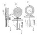
- FIG. 3Aillustrates a malecot member 14 in its natural retracted state and FIG. 3B shows this expansible member 14 in its expanded state at a distal end 12 B of the catheter 11 .
- FIG. 4Aillustrates another embodiment that comprises a tubular braided mesh member 14 in its free retracted state at a distal end 12 C of the catheter.
- FIG. 4Billustrates this expansible member 14 in its deployed expanded configuration. The manner in which these expansible members 14 may be assembled onto the catheter 11 and the way in which these members 14 may interact with other components of the device 10 are similar.
- a proximal end of expansible member 14is connected to the distal end 12 of tubular member 11 at connection point 15 .
- the connectionmay be made with a crimp process, use of shrink tubing such as polyester tubing, adhesives such as glue, heat staking member 14 into member 11 , or a combination thereof.
- a distal end of expansible member 14is connected to the push/pull member 16 at connection point 17 .
- Push/pull member 16may be formed from metals (e.g., stainless steel or NITINOL®) or from polymer materials such as nylon, polyurethane, polyimide, PEEK®, PEBAX®, and the like.
- Member 16has a diameter small enough to go through the tubular member 11 and a length that is long enough to traverse the length of the tubular member 11 .
- the proximal end 13 of members 11 and 16incorporate a handle assembly 18 .
- a first part of the handle 19is connected to the proximal end 13 of member 11 .
- a second part of the handle 20is connected to proximal end of member 16 .
- Handle parts 19 and 20provide for an enhanced grip on members 11 and 16 , allowing the user to more conveniently move these members with respect to each other for the purpose of deploying and retracting the expansible member 14 . Moving parts 19 and 20 away from each other causes the deployment of expansible member 14 and moving them towards each other causes the retraction of expansible member 14 .
- handle assembly 18 Amay be designed to allow the deployed state of expansible member 14 to be held in position. This is because the lack of friction allows members 11 and 16 to move freely with respect to each other forcing the expansible member 14 back to its natural retracted state.
- locking features 21 and 22 of handle parts 19 and 20respectively may be locked to maintain the expansible member 14 in a deployed configuration.
- parts 19 and 20are moved apart until features 21 and 22 completely slide over each other.
- Handle part 20can then be twisted with respect to part 19 by approximately 180° degrees, allowing the proximal end 21 of handle part 19 to rest over the distal end 22 of handle part 20 , as shown in FIG.
- FIG. 5BA top view of this locking mechanism is illustrated in FIG. 5C showing the handle assembly in a deployed position.
- This locking mechanismmay be beneficial to greatly reduce the chances of parts 19 and 20 slipping relative to each other causing unintended retraction.
- a handle housing 35may at least be partially disposed over parts 19 or 20 .
- housing member 35is attached to the first part of the handle 19 and is long enough that when member 14 is deployed and features 23 and 24 are in contact, member 35 extends proximally beyond feature 22 .
- device 10also includes a second flexible tubular member 25 that is slidably disposed over the first tubular member 11 .
- Second member 25is formed from a variety of medical grade materials, including polymer materials such as nylon, polyurethane, polyimide, PEEK®, PEBAX®, and the like. Second member 25 is shorter than first member 11 and may have a length in range from about 5 cm to about 40 cm, preferably in the range from about 10 cm to about 20 cm.
- a distal end of member 25is connected to the tension coil spring 26 .
- Tension coil spring 26comprises a helical coil spring having a central passage which encompasses first member 11 , wherein its distal end is connected to member 11 proximal the expansible member 14 at connection point 15 .
- Tensioning member 26may be formed from a variety of medical grade materials, including suitable metals such as stainless steel or preferably shape memory or superelastic metals such as NITINOL®.
- suitable metalssuch as stainless steel or preferably shape memory or superelastic metals such as NITINOL®.
- the amount of force that expansible member 14 can exert against a vessel wall at the puncture siteprimarily depends on the diameter of the wire used, the diameter of the resulting coil, the pitch of the coil, and/or the total number of the loops in the coil of the tensioning member 26 .
- the number of loops in the coil spring 26may be in the range from about 1 loop to about 30 loops, preferably in the range from about 3 loops to about 20 loops.
- the coilsare preferably wound tightly with little or no pitch between the loops when the coil 26 is at its relaxed state.
- the wire diameter used to fabricate the coil 26may be in the range from about 0.02 mm to about 1 mm, preferably in the range from about 0.05 mm to about 0.5 mm.
- the fabricated coil 26may have a diameter in the range from about 1 mm to about 10 mm, preferably in the range from about 1.5 mm to about 5 mm in a relaxed state.
- the diameter of the tension coil spring 26 in the preferred embodiment of this inventionis chosen to be greater than the inside diameter of an introducer sheath. For example, when a 5 Fr sheath is used the diameter of coil 26 would be greater than 1.75 mm.
- the distal end 12 of device 10may include a tip deflector 27 .
- Deflector 27prevents element 17 from damaging the vessel wall on the opposite side of the puncture site. This may happen if the user excessively compresses the skin at or adjacent to the puncture site, which potentially could happen when the device 10 is being removed.
- Deflector 27may be formed from a variety of medical grade materials, including flexible metal coil materials or polymer materials such as nylon, polyurethane, polyimide, PEEK®, PEBAX®, and the like. In one embodiment, deflector 27 may be formed from a small diameter wire, possibly the extension of member 16 , coated with a soft polymer material.
- Deflector 27will generally have a diameter equal to or smaller than the catheter diameter at element 17 and a length in the range from about 1 cm to about 10 cm, preferably from about 2 cm to about 4 cm. A welding process may be utilized to provide for a short and strong connection point at element 17 . It will be appreciated however that the need for a deflector tip 27 may be alleviated if element 17 itself is made short and blunt.
- device 10may be equipped with a catheter loading element 28 to facilitate insertion of the device 10 through the sheath when the tensioning member 26 at its relaxed state is larger than the inner diameter of the introducer sheath.
- Loading element 28generally comprises an elongated tubular member 29 .
- An outer diameter of member 29is smaller than the opening in a hub of the sheath and can penetrate a seal in the sheath.
- An inner diameter of loader 28is large enough to allow the catheter 11 to completely slide through.
- Loader 28has a length long enough to at least contain all the elements of the catheter 11 distal to and including the tensioning member 26 .
- Loader 28may include a feature 30 at a proximal end.
- This feature 30may be used as a stop against the hub of the introducer sheath, preventing the loading element 28 from completely sliding into a lumen of the sheath.
- Loading element 28may be formed from coiled stainless steel tubing or polymer materials such as nylon, polyurethane, polyimide, PEEK®, PEBAX®, and the like.
- introduction of the device 10 A into the sheath and removal of the device 10 A from the bodymay also be facilitated by incorporating a locking mechanism 33 at a proximal end of second tubular member 25 that may be interlocked with a feature 34 on a distal end of handle 19 .
- the locking mechanism 33 , 34allows tensioning member 26 to be maintained in a stretched state so as to reduce the coil diameter to below that of the inner diameter of the introducer sheath and thereby allowing the device 10 A to slide through the sheath without interference.
- locking features on the catheter 11may interlock with the locking mechanism 33 on member 25 . Even when member 25 is equipped with an interlocking mechanism 33 so that tensioning member 26 does not interfere with the sheath, loader 28 may still provide for enhanced introduction of the device 10 A into the sheath.
- tubular member 11has a visual mark 31 .
- alignment of mark 31 with the opening of the hub of the sheathindicates that catheter 10 has been advanced enough through the sheath to expose the expansible member 14 in the lumen of the vessel.
- element 30 of loading element 28is against the hub of the sheath
- alignment of mark 31 with the proximal end of feature 30may indicate appropriate advancement of the expansible member 14 in the vessel lumen.
- alignment of the distal end of handle 19 with the hub of the sheath or loading element 30may eliminate the need for mark 31 .
- mechanical meansmay be utilized for proper location of the expansible member 14 within the lumen of the vessel.
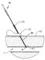
- FIG. 8Adepicts an existing introducer sheath 40 through an opening in a skin surface 46 , tissue tract in fascia 45 , and vessel wall 43 and seated in a vessel lumen 41 at the completion of a catheterization procedure.
- Device 10 including loading element 28is then inserted through the hub of the sheath 40 so that loading element 28 at least penetrates the seal of sheath 40 or until feature 30 is against the hub of the sheath 40 , as shown in FIG. 8B .
- Loader 28may now be removed.
- device 10 with loader 28 presentcan be pushed into sheath 40 until the identifying mark 31 on member 11 is aligned with feature 30 of loading element 28 .
- expansible member 14is then deployed by holding part 19 of handle assembly 18 A stationary and moving member 20 proximally, as depicted by arrow 8 and described in detail with respect to FIGS. 5A through 5C .
- Second tubular member 25may then be pulled proximally until resistance is felt indicating that expansible member 14 is at the distal end of sheath 40 . If member 25 is equipped with a locking mechanism 33 in a locked position, member 11 or the handle assembly 18 A may be grasped to pull the device 10 proximally and seat member 14 against the tip of the sheath 40 .
- the sheath 40 at the hubmay be gently removed from the body so as to seat the expansible member 14 .
- sheath 40is removed from the body exposing the loops of the coil 26 and lodging them into the fascia 45 one loop at a time. Loader 28 along with sheath 40 are removed and may be discarded.
- the interference between the loops of the coil 26 and fascia 45provides the hold and retains expansible member 14 under tension against the vessel wall 43 at the puncture site 42 .
- the tension applied to the expansible member 14is sufficient for complete hemostasis, typically in a range from about 0.5 ounce to 30 ounces.
- the sheath 40 and/or loader 28are removed and the coil 26 gets embedded in the tissue 45 , the amount of the tension at the puncture site 42 may drop as the coil 26 recoils some to engage itself in the tissue 45 .
- the amount in the reduction of tensionis dependant on the tissue type 45 surrounding the puncture site 42 , the nature of the coil spring 26 , and the thickness of the fascia 45 . These factors have been considered in the proper design of the coil 26 of the present invention.
- second tubular member 25may be moved proximally and released increasing the amount of compression that expansible member 14 applies on the vessel wall 43 .
- the increase in the pull forcemay be limited by the amount of proximal movement of member 25 , which can be determined by the proper length of member 25 and the distance between the proximal end of member 25 and distal end of handle part 19 .
- the pull forcemay be limited by interference of members 25 and 19 .
- the pull forcemay also be limited by interference between the coil 26 and the first tubular member 11 . In particular, the closer the diameter of member 11 to the inside diameter of coil 26 , the less stretch member 26 can experience before the coil diameter is reduced enough to interfere with member 11 . In the above methodologies, when second member 25 stops moving with respect to first member 11 , that may be an indication that the maximum allowable and safe pull force has been reached.
- Device 10remains in the body for an adequate period of time. Occlusive compression may be applied proximal to the puncture site 42 when the device 10 is to be removed. Expansible member 14 is retracted by manipulation of handle assembly 18 A and member 25 is grasped so as to pull the device 10 out of the body. Pulling on member 25 causes coil 26 to stretch, reducing the coil diameter, and consequently reducing the amount of interference between coil 26 and fascia 45 . If device 10 is equipped with locking features 33 and 34 , removal of device 10 may be accomplished by first pulling on member 25 proximally and interlocking features 33 and 34 . This easily disengages device 10 from the fascia 45 . Removal of the device 10 may be followed by a few minutes of manual compression at the skin surface 46 to achieve complete hemostasis.
- device 10may include an external clip 50 .
- Clip 50couples member 25 and rests on the patient's skin surface 46 .
- Clip 50may be used as a safety feature to further secure and keep expansible member 14 under tension. It may also be used when greater tension is desired than that provided by interaction of coil 26 with sheath 40 and fascia 45 alone.
- coil member 26may be intended to function only as a tensioning member.
- Coil 26 in this embodimentmay have a diameter smaller than the inner diameter of the sheath 40 and be formed from elastomeric material. This elastomeric member is preferably in a form of a tube which is attached to the first member 11 at point 15 and to the distal end of second member 25 .
- member 25is used to place expansible member 14 against the vessel wall 43 at the puncture site 42 and to apply the required tension to the device.
- the substantial hold once the tension is appliedis then provided by external means, such as the external clip 50 .
- This devicemay have the advantage of being easier to load and insert through the sheath 40 as the external clip 50 provides anchoring.
- the expansible member 60preferably comprises coiled string constructed from small diameter tubing that is flexible.
- the tubular configurationmay have a suture or small diameter wire in its lumen to add to its tensile strength.
- Flexible member 60may be formed from medical grade materials, including polymer materials such as nylon, polyurethane, polyimide, PEEK®, PEBAX®, and the like. Flexible member 60 can be coiled into an expanded configuration comprising a disc or dome shape 61 . Adjacent loops of member 60 may be adhered lightly through a heating or a gluing process.
- FIG. 9AMember 60 at the center is fed through a tube 62 , wrapped around tube 62 , and is housed in a tubular member 63 , as shown in FIG. 9A .
- tube 62is pushed forward to expose the expansible member 61 .
- the expansible member 61unfolds into a disc or a dome configuration as illustrated in FIG. 9B .
- the sealing processis attained by pulling on tube 62 , allowing the expansible member 61 to press against the puncture site.
- Retractionis effected by pulling coil 60 through tube 62 , causing the loops of the expansible member 61 to unwind as depicted by FIG. 9C .
- Still further embodiments of such an expansible memberare disclosed in U.S. patent application No. 2003/0120291, which describes a temporary seal and method for facilitating anastomosis and is also incorporated herein by reference.
- FIGS. 10 through 13Ban exemplary self-tensioning vascular occlusion device 70 for hemostasis of vascular puncture sites according to another embodiment of the present invention is illustrated.
- Device 70is similar in many respects to device 10 of FIG. 1 except in regards to the tensioning element.
- the tensioning element 86 of device 70comprises a helical coil spring which has a smaller diameter that applies tension but does not cause its engagement with the surrounding tissue tract fascia 45 , and consequently does not provide means for maintaining the tension.
- Tensioning element 86generally has an outer diameter that is smaller than that of the introducer sheath 40 .
- the tensionis applied by a user grabbing a grip element 85 , and pulling the tensioning element 86 in a proximal direction to achieve hemostasis.
- the tensioning element 86 in this embodimentprovides tension to an expansible member 74 (similar to expansible member 14 ). Tension is maintained by utilization of the external clip 50 . Aside from this difference mentioned above with respect to the tensioning element 86 , the fundamental principles of device 70 remains substantially the same as device 10 .
- Tensioning element 86may be formed from suitable medical grade spring coil materials such as superelastic metals (e.g., NITINOL®) or stainless steel.
- the tensioning element 86has a diameter in a range from about 0.5 mm to about 2.5 mm, preferably from about 0.75 mm to about 1.25 mm.
- an inside diameter of the spring coil 86is large enough so that a catheter shaft 71 (similar to tubular member 11 ) can be slidably received through a lumen of the tensioning element 86 .
- the outside diameter of spring coil 86is smaller than an inside diameter of the introducer sheath 40 .
- the tensioning element 86is sufficiently long enough to extend outside the fascia 45 so that it may be adequately pulled via the grip element 85 to achieve hemostasis.
- the length of the tensioning element 86may be in a range from about 2 cm to about 25 cm, preferably from about 8 cm to about 15 cm.
- a distal end of the tensioning element 86is coupled to the catheter shaft 71 at point 75 .
- a proximal end of tensioning element 86couples the grip element 85 .
- the grip element 85comprises a tubular member that provides means for the user to grab the tensioning element 86 and apply consistent tension to the catheter 71 .
- the grip element 85may be formed from a variety of medical grade materials, including metals or polymer materials such as nylon, polyurethane, polyimide, PEEK®, PEBAX®, polyester and the like.
- the tubular member 85is then attached to tensioning element 86 by means of glue or a heat staking process.
- the grip element 85may optionally be formed from shrink tubing materials and attached to the tensioning element 86 by the application of heat.
- the expansible member 74may at least partially or preferably be fully covered with an elastomeric membrane material 96 .
- Membrane 96may be formed from a variety of medical grade materials, such as thermoplastic elastomers (e.g., CHRONOPRENE® or POLYBLEND®) having durometers in a range from 15 A to about 40 A.
- Membrane 96may be connected at a distal connection point 77 and a proximal connection point 75 .
- Adhesivessuch as LOCTITE® 4014 may be used to attach membrane 96 to the catheter 71 .
- Membrane 96preferably has a diameter that is sufficient to cover the expansible member 74 .
- the membrane 96may additionally form a membrane tip 97 at a distal end of the catheter 71 so as to provide a soft and blunt point for percutaneous access.
- a proximal end of the catheter 70comprises deployment means 78 .
- FIGS. 12A and 13Aillustrate one embodiment of the handle assembly 78 .
- FIGS. 12B and 13Billustrate the corresponding state of the occluding member 74 in a retracted and expanded configuration respectively.
- a proximal end of handle assembly 78comprises an actuating assembly 101 which is coupled to a push/pull member 76 (similar to member 16 ). Proximal movement of assembly 101 relative to a grip handle 102 deploys the expansible member 74 .
- the grip handle 102comprises a tubular member 103 formed from suitable metal tubing (e.g., stainless steel) or polymer materials (e.g., polyurethane, polyimide, PEEK®, PEBAX®, and the like).
- Member 103is coupled to the catheter shaft 71 by means of an expander element 104 so as to account for the difference in an outside diameter of catheter 71 and an inside diameter of member 103 .
- Elements 71 , 103 , and 104may be attached by the use of adhesives.
- Member 103further includes a feature 105 , such as an indentation from a crimping process when element 103 is formed from a stainless steel or other metallic hypotube. Indentation 105 provides interference to element 106 of the actuating assembly 101 .
- Actuating assembly 101further includes a tubular member 107 that is attached to the push/pull member 76 by a crimp process and/or adhesive.
- Member 107provides added stiffness to the actuating mechanism 101 as well as provides for a larger surface area that consequently allows for enhanced adhesion of elements 106 , 108 , and 109 to member 107 .
- These elementsmay comprise individual, separate parts, preferably formed from polymer materials such as polyurethane, polyimide, PEEK®, PEBAX®, and the like. These elements may be optionally incorporated into element 107 through an over molding process.
- a proximal end of detent 106may have a shallow angle in relation to the catheter shaft 71 so as to provide simplified deployment of the expansible member 74 .
- a distal end of detent 106may be more perpendicular to the catheter shaft 71 so as to provide more interference to feature 105 , thereby requiring greater force to undeploy the expansible member 74 .
- the increased undeployment forceis desirable to avoid inadvertent device collapse.
- indentation 105may be designed so that a distal side of the feature has a much shallower angle in relation to the catheter shaft 71 than a proximal side.
- Elements 108 and 109primarily provide support and alignment of the actuating assembly 101 .
- Element 109may be formed from a bright distinct color to indicate when the expansible member 74 is deployed.
- Element 110comprises a tubular member, preferably having the same outer diameter as member 103 . A distal end of tubular member 110 abuts a proximal end of member 103 so as to provide a positive stop to the movement of the actuating assembly 101 during the undeployment of the expansible member 74 .
- Cap 111 at the most proximal end of the device 70provides a soft tip for easier undeployment of expansible member 74 .
- Cap 111may be formed from rubber or similar materials.
- handle assembly 78is held by grabbing onto element 103 with one hand and element 110 with the other hand. Element 110 is then pulled in a proximal direction while holding element 103 stationary. As element 110 is pulled back, detent 106 slides over indentation 105 until it is completely moved to the proximal side of feature 105 , as seen in FIG. 13A . The interference between elements 105 and 106 keeps the expansible member 74 in the deployed configuration. Undeployment of the device 70 may be effected with a single hand. In particular, member 103 may be grabbed by the palm of the hand while the thumb presses on cap 111 . This causes the actuating mechanism 101 to move forward and the detent member 106 to slide distally over feature 105 , as seen in FIG. 12A , resulting in the retraction of the expansible member 74 .
- Handle assembly 120comprises an actuating assembly 121 and a grip handle 122 .
- Grip element 122comprises a tubular member 123 coupled to the catheter shaft 71 by means of an expander element 124 to account for the difference in the outside diameter of catheter 71 and an inside diameter of element 123 .
- Tubular member 123 and the expander 124may be formed from suitable metal tubing (e.g., stainless steel) or polymer materials such as nylon, polyurethane, polyimide, PEEK®, PEBAX®, and the like.
- Member 123also includes feature 125 .
- Feature 125provides interference to a flaring element 126 of a latching component of the actuating assembly 121 .
- Actuating assembly 121includes both a latching component and an unlatching component.
- the latching componentcomprises an elongated tubular element 127 coupled to the push/pull member 76 .
- Feature 128 of the latching elementprovides alignment for sliding the latching element through the handle assembly 120 .
- Feature 128also prevents excessive pull on the expansible member 74 by abutting feature 125 of the grip handle 122 .
- Feature 129 of the latching elementallows for interference with the unlatching component of the actuation mechanism 121 when the expansible member 74 is deployed.
- the unlatching component of the actuating assembly 121comprises a tubular member 130 that slides between elements 123 and 126 .
- a proximal end of member 130is coupled to a cap 131 .
- a coil spring 132is housed in the cap 131 and rests against feature 129 of the latching element.
- grip handle 122is held stationary at element 123 with one hand while cap 131 is moved in a proximal direction with the other hand. Interference between the unlatching component 130 and feature 129 of the latching component pulls both components proximally, deploying expansible member 74 and sliding flare element 126 over feature 125 of the grip handle 122 . Once the flare element 126 clears the feature 125 , flare element 126 expands laterally. Further proximal movement of cap 132 is limited by interference of element 128 of the latching component with feature 125 . Releasing cap 132 results in the flare element 126 resting against a proximal end of feature 125 and latching the expansible member 74 in an expanded state, as shown in FIG. 14B .
- Retraction of the expansible member 74may be effected by pushing cap 131 in a distal direction relative to the grip handle 122 .
- This operationmay be easily performed single handedly.
- Pushing cap 131would simultaneously push the unlatching element 130 and compress and load coil spring 132 .
- element 130is pushed distally, it slides between the handle element 123 and the flare element 126 , causing element 126 to collapse medially as shown in FIG. 14C .
- Distal movementcontinues until a distal end of the flare element 126 clears a proximal end of feature 125 .
- Coil spring 132then distally propels elements 126 , 127 , 128 , and 129 along with push/pull member 76 , causing the expansible member 74 to retract. Releasing cap 131 places the handle assembly 120 back to an undeployed configuration, as seen in FIG. 14A .
- FIG. 15Adepicts an existing introducer sheath 40 through an opening in a skin surface 46 , tissue tract in fascia 45 , and vessel wall 43 and seated in a vessel lumen 41 at the completion of a catheterization procedure.
- Device 70is then inserted through the hub of the sheath 40 and advanced until the expansible member 74 is outside the sheath 40 and in vessel lumen 41 , as shown in FIG. 15B . This positioning may be indicated by a mark on the catheter 71 .
- the device 70may be advanced to a feature on the catheter 71 , for example to a distal end of the handle assembly 78 . It will be appreciated that a loader element is not necessary to the present embodiment as the tensioning element 86 in its relaxed state has a smaller diameter than the inside diameter of the sheath 40 .
- the expansible member 74is then deployed by operation of the handle assembly 78 as described above. Sheath 40 is then removed from the body, leaving expansible member 74 seated at the puncture site 42 .
- the grip element 85is exposed and pulled in a proximal direction as the sheath 40 is completely removed and discarded. Grip element 85 is moved proximally to provide an adequate amount of tension to the deployed expansible member 74 to achieve hemostasis.
- the amount of tension applied to the expansible member 74is in a range from about 0.5 ounce to 30 ounces.
- the substantial hold once the tension is appliedis then provided by external means. In this case, the thin and small external clip 50 seated against the skin surface 46 maintains tension as seen in FIG. 15D .
- This device 70may have the advantage of being easier to load and insert through the sheath 40 as the external clip 50 provides anchoring.
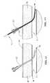
- Dilator 150allows the user to reintroduce the sheath 40 over the vascular occlusion device 70 and replace it with the introducer sheath 40 .
- Dilator 150may be located proximal to the expansible member 74 and formed from suitable medical grade materials, such as metals (e.g., stainless steel) or preferably polymer materials (e.g., nylon, polyurethane, polyimide, PEEK®, PEBAX®, polyester and the like). Dilator 150 may be molded over or glued to the tensioning element 86 .
- Dilator 150may have a length in a range from 0.1 inch to the length of the tensioning element 86 , preferably in a range from about 0.25 inch to about 1.0 inch. Dilator 150 may be flexible and attached at a distal end to the tensioning element 86 so as to preserve the functionality of the tensioning element 86 , particularly when dilator 150 is of longer length. Dilator 150 may have a diameter that accommodates an inside diameter of the sheath 40 or a second catheter to be reintroduced as the diameter of feature 150 defines the size of the sheath to be reinserted. For example, the dilator 150 may have a diameter of about 0.065 inch for a 5 Fr sheath and 0.078 inch for a 6 Fr sheath.
- Dilator 150comprises leading edges 152 and trailing edges 153 which are tapered and a landing 151 therebetween.
- Leading edges 152allow for easy introduction of the introducer sheath 40 through the puncture site 42 in the vessel wall 43 .
- the trailing edges 153allow for convenient introduction of the sheath 40 over the dilator 150 .
- Landing 151allows the user to have some tolerance in locating the introducer sheath 40 over the device 70 prior to advancing the sheath 40 into the vessel 41 . Hence, recovery of vascular access is facilitated by the dilator 150 which provides enhanced column strength to the device 70 and ensures smooth transition of the sheath 40 .
- Dilator 150may be positioned anywhere along the length of the tensioning element 86 .
- the correct sheath sizeis selected based upon the diameter of the dilator 150 .
- a proximal end of device 70is inserted into a distal end of the introducer sheath 40 .
- Device 70is then advanced through the sheath 40 until a proximal end of the device 70 penetrates the seal in the hub of the sheath 40 and exits the proximal end of the introducer sheath 40 .
- the sheath 40is then advanced into position so that the distal end of the sheath 40 resides on landing 151 .
- Device 70is then retracted via manipulation of the handle assembly 78 . Following retraction, the sheath 40 and the device 70 are held together and advanced distally into the vessel lumen 41 .
- Device 70is then removed, leaving the sheath 40 in the vessel.
- device 70performs similar in function to a guidewire subsequent to vascular occlusion to allow for recovery of vascular access.
- a non-integrated dilator 160may be employed as an alternative to the integrated dilator 150 .
- Dilator 160is similar to dilator 150 in that it comprises tapered leading 163 and trailing 164 edges with a landing 165 therebetween and is formed from similar materials as described above.
- Dilator 160further comprises a longitudinal axial slit 162 along a length thereof that is wider than the catheter shaft 71 and narrower than the tensioning element 86 .
- Dilator 160also includes a central longitudinal lumen 161 having a diameter that is larger than that of the grip element 85 but smaller than a distal end of the device 70 at point 75 .
- Dilator 160has a length that is less than the distance between a distal end of the handle assembly 78 and a proximal end of the grip element 85 .
- dilator 160may take on any desired diameter so as to allow for the introduction of a variety of sheaths 40 as the dilator 160 is not integrated into the device 70 .
- the desired diameter of dilator 160is selected for a particular sheath size.
- Dilator 160is then placed onto the device 70 by sliding the catheter shaft 71 into the slit 162 .
- Dilator 160is then pushed forward so that the grip element 85 extends through lumen 161 .
- Dilator 160is further advanced until it abuts a proximal end of element 75 .
- the appropriate sheath 40is then advanced over device 70 until the distal end of the sheath 40 is positioned in the landing 165 .
- Device 70is then retracted by manipulation of the handle assembly 78 . Following retraction, the sheath 40 and the device 70 are both advanced into the vessel lumen 41 .
- Device 70 along with the dilator 160are completely removed, leaving the introducer sheath 40 behind in the vessel 41 .
Landscapes
- Health & Medical Sciences (AREA)
- Surgery (AREA)
- Life Sciences & Earth Sciences (AREA)
- Medical Informatics (AREA)
- Animal Behavior & Ethology (AREA)
- Engineering & Computer Science (AREA)
- Biomedical Technology (AREA)
- Heart & Thoracic Surgery (AREA)
- Cardiology (AREA)
- Molecular Biology (AREA)
- Nuclear Medicine, Radiotherapy & Molecular Imaging (AREA)
- General Health & Medical Sciences (AREA)
- Public Health (AREA)
- Veterinary Medicine (AREA)
- Surgical Instruments (AREA)
- Infusion, Injection, And Reservoir Apparatuses (AREA)
- Media Introduction/Drainage Providing Device (AREA)
Abstract
Description
Claims (9)
Priority Applications (5)
| Application Number | Priority Date | Filing Date | Title |
|---|---|---|---|
| US10/974,008US7993366B2 (en) | 2004-05-27 | 2004-10-25 | Self-tensioning vascular occlusion device and method for its use |
| EP05759503.5AEP1748733B1 (en) | 2004-05-27 | 2005-05-18 | Self-tensioning vascular occlusion device |
| PCT/US2005/017688WO2005117715A2 (en) | 2004-05-27 | 2005-05-18 | Self-tensioning vascular occlusion device and method for its use |
| JP2007515192AJP4954063B2 (en) | 2004-05-27 | 2005-05-18 | Hemostatic device |
| US13/868,775US9427221B2 (en) | 2004-04-09 | 2013-04-23 | Hemostasis-enhancing device and method for its use |
Applications Claiming Priority (2)
| Application Number | Priority Date | Filing Date | Title |
|---|---|---|---|
| US10/857,177US7572274B2 (en) | 2004-05-27 | 2004-05-27 | Self-tensioning vascular occlusion device and method for its use |
| US10/974,008US7993366B2 (en) | 2004-05-27 | 2004-10-25 | Self-tensioning vascular occlusion device and method for its use |
Related Parent Applications (1)
| Application Number | Title | Priority Date | Filing Date |
|---|---|---|---|
| US10/857,177Continuation-In-PartUS7572274B2 (en) | 2004-04-09 | 2004-05-27 | Self-tensioning vascular occlusion device and method for its use |
Publications (2)
| Publication Number | Publication Date |
|---|---|
| US20050267522A1 US20050267522A1 (en) | 2005-12-01 |
| US7993366B2true US7993366B2 (en) | 2011-08-09 |
Family
ID=35463298
Family Applications (1)
| Application Number | Title | Priority Date | Filing Date |
|---|---|---|---|
| US10/974,008Expired - LifetimeUS7993366B2 (en) | 2004-04-09 | 2004-10-25 | Self-tensioning vascular occlusion device and method for its use |
Country Status (4)
| Country | Link |
|---|---|
| US (1) | US7993366B2 (en) |
| EP (1) | EP1748733B1 (en) |
| JP (1) | JP4954063B2 (en) |
| WO (1) | WO2005117715A2 (en) |
Cited By (10)
| Publication number | Priority date | Publication date | Assignee | Title |
|---|---|---|---|---|
| US20100010480A1 (en)* | 2008-07-14 | 2010-01-14 | Primaeva Medical, Inc. | Devices and methods for percutaneous energy delivery |
| US20110046663A1 (en)* | 2009-08-24 | 2011-02-24 | St. Jude Medical Puerto Rico Llc | Polymer membrane locator with built-in stress relief structure |
| US8845683B2 (en) | 2008-08-26 | 2014-09-30 | St. Jude Medical, Inc. | Method and system for sealing percutaneous punctures |
| US10363021B2 (en) | 2005-12-13 | 2019-07-30 | Cardiva Medical, Inc. | Vascular closure devices and methods providing hemostatic enhancement |
| US10531868B2 (en) | 2017-12-01 | 2020-01-14 | Cardiva Medical, Inc. | Apparatus and methods for accessing and closing multiple penetrations on a blood vessel |
| US10960101B2 (en) | 2006-05-26 | 2021-03-30 | Z-Medica, Llc | Clay-based hemostatic agents |
| US10960100B2 (en) | 2012-06-22 | 2021-03-30 | Z-Medica, Llc | Hemostatic devices |
| US11007218B2 (en) | 2010-09-22 | 2021-05-18 | Z-Medica, Llc | Hemostatic compositions, devices, and methods |
| US11167058B2 (en) | 2005-02-15 | 2021-11-09 | Virginia Commonwealth University | Hemostasis of wound having high pressure blood flow |
| WO2022266195A1 (en) | 2021-06-18 | 2022-12-22 | Silk Road Medical, Inc. | Systems and methods for vascular interventions |
Families Citing this family (34)
| Publication number | Priority date | Publication date | Assignee | Title |
|---|---|---|---|---|
| US7335220B2 (en)* | 2004-11-05 | 2008-02-26 | Access Closure, Inc. | Apparatus and methods for sealing a vascular puncture |
| US7223266B2 (en) | 2003-02-04 | 2007-05-29 | Cardiodex Ltd. | Methods and apparatus for hemostasis following arterial catheterization |
| US7572274B2 (en)* | 2004-05-27 | 2009-08-11 | Cardiva Medical, Inc. | Self-tensioning vascular occlusion device and method for its use |
| US20080154303A1 (en) | 2006-12-21 | 2008-06-26 | Cardiva Medical, Inc. | Hemostasis-enhancing device and method for its use |
| US20050267520A1 (en) | 2004-05-12 | 2005-12-01 | Modesitt D B | Access and closure device and method |
| US7678133B2 (en) | 2004-07-10 | 2010-03-16 | Arstasis, Inc. | Biological tissue closure device and method |
| EP1814478A4 (en) | 2004-11-22 | 2011-05-18 | Cardiodex Ltd | Techniques for heat-treating varicose veins |
| CN103190942A (en) | 2005-05-12 | 2013-07-10 | 阿尔斯塔西斯公司 | Access and closure device and method |
| US8911472B2 (en) | 2005-12-13 | 2014-12-16 | Cardiva Medical, Inc. | Apparatus and methods for delivering hemostatic materials for blood vessel closure |
| US7691127B2 (en)* | 2005-12-13 | 2010-04-06 | Cardiva Medical, Inc. | Drug eluting vascular closure devices and methods |
| US11871916B2 (en)* | 2005-12-13 | 2024-01-16 | Cardiva Medical, Inc. | Vascular closure devices and methods providing hemostatic enhancement |
| WO2008033964A2 (en)* | 2006-09-13 | 2008-03-20 | Accessclosure, Inc. | Apparatus for sealing a vascular puncture |
| EP2182875A4 (en) | 2007-08-15 | 2011-08-24 | Cardiodex Ltd | Systems and methods for puncture closure |
| US8029533B2 (en)* | 2008-04-04 | 2011-10-04 | Accessclosure, Inc. | Apparatus and methods for sealing a vascular puncture |
| US9364206B2 (en) | 2008-04-04 | 2016-06-14 | Access Closure, Inc. | Apparatus and methods for sealing a vascular puncture |
| JP2011528605A (en) | 2008-07-21 | 2011-11-24 | アルスタシス,インコーポレイテッド | Device, method, and kit for forming a tube in tissue |
| WO2010056915A1 (en) | 2008-11-12 | 2010-05-20 | Accessclosure, Inc. | Apparatus and methods for sealing a vascular puncture |
| US9913634B2 (en) | 2009-02-20 | 2018-03-13 | Boston Scientific Scimed, Inc. | Locking element for vascular closure device |
| US8375553B2 (en)* | 2009-02-20 | 2013-02-19 | Boston Scientific Scimed, Inc. | Locking element for vascular closure device |
| US8845682B2 (en) | 2009-10-13 | 2014-09-30 | E-Pacing, Inc. | Vasculature closure devices and methods |
| US20110106012A1 (en)* | 2009-10-29 | 2011-05-05 | Velarde Franz E | Sheath Introducer with Self-Anchoring Mechanism |
| AU2011203850A1 (en)* | 2010-01-11 | 2012-08-02 | Arstasis, Inc. | Device for forming tracts in tissue |
| US9757105B2 (en) | 2012-03-23 | 2017-09-12 | Accessclosure, Inc. | Apparatus and methods for sealing a vascular puncture |
| US8721680B2 (en) | 2012-03-23 | 2014-05-13 | Accessclosure, Inc. | Apparatus and methods for sealing a vascular puncture |
| US20130317438A1 (en) | 2012-05-25 | 2013-11-28 | Arstasis, Inc. | Vascular access configuration |
| US20130317481A1 (en) | 2012-05-25 | 2013-11-28 | Arstasis, Inc. | Vascular access configuration |
| US9743920B2 (en)* | 2012-08-20 | 2017-08-29 | Terumo Puerto Rico, L.L.C. | Flexible tamping member |
| US20140142618A1 (en)* | 2012-09-12 | 2014-05-22 | ProMed, Inc. | Systems and Methods for Improved Vessel Access Closure |
| EP3021762B1 (en) | 2013-07-15 | 2020-03-04 | E-Pacing, Inc. | Vasculature closure devices |
| EP2962721B1 (en)* | 2014-07-04 | 2019-05-08 | Abiomed Europe GmbH | Sheath for sealed access to a vessel |
| EP4574200A3 (en) | 2014-07-04 | 2025-09-10 | Abiomed Europe GmbH | Sheath |
| KR20240150538A (en) | 2018-01-29 | 2024-10-15 | 액세스클로저, 아이엔씨. | Apparatus and method for sealing a vascular puncture |
| US12102293B2 (en)* | 2019-08-30 | 2024-10-01 | Biosese Webster (Israel) Ltd. | ENT guidewire |
| CN117796872B (en)* | 2024-01-04 | 2024-07-16 | 南京思脉德医疗科技有限公司 | Vascular occlusion hemostasis device |
Citations (103)
| Publication number | Priority date | Publication date | Assignee | Title |
|---|---|---|---|---|
| US4721507A (en)* | 1986-06-05 | 1988-01-26 | Thomas J. Fogarty | Shear force gauge and method and apparatus for limiting embolectomy shear force |
| US4744364A (en) | 1987-02-17 | 1988-05-17 | Intravascular Surgical Instruments, Inc. | Device for sealing percutaneous puncture in a vessel |
| US4850975A (en)* | 1987-03-27 | 1989-07-25 | Yuichi Furukawa | Catheter introducer for angiography |
| US4852568A (en) | 1987-02-17 | 1989-08-01 | Kensey Nash Corporation | Method and apparatus for sealing an opening in tissue of a living being |
| US4890612A (en) | 1987-02-17 | 1990-01-02 | Kensey Nash Corporation | Device for sealing percutaneous puncture in a vessel |
| US5015255A (en) | 1989-05-10 | 1991-05-14 | Spine-Tech, Inc. | Spinal stabilization method |
| US5061274A (en) | 1989-12-04 | 1991-10-29 | Kensey Nash Corporation | Plug device for sealing openings and method of use |
| US5092866A (en) | 1989-02-03 | 1992-03-03 | Breard Francis H | Flexible inter-vertebral stabilizer as well as process and apparatus for determining or verifying its tension before installation on the spinal column |
| US5108421A (en) | 1990-10-01 | 1992-04-28 | Quinton Instrument Company | Insertion assembly and method of inserting a vessel plug into the body of a patient |
| US5108420A (en) | 1991-02-01 | 1992-04-28 | Temple University | Aperture occlusion device |
| US5171259A (en) | 1990-04-02 | 1992-12-15 | Kanji Inoue | Device for nonoperatively occluding a defect |
| WO1992022252A1 (en) | 1991-06-18 | 1992-12-23 | Ashridge Ag | Sealing device for a blood vessel or the like |
| US5197971A (en) | 1990-03-02 | 1993-03-30 | Bonutti Peter M | Arthroscopic retractor and method of using the same |
| US5222974A (en)* | 1991-11-08 | 1993-06-29 | Kensey Nash Corporation | Hemostatic puncture closure system and method of use |
| US5258031A (en) | 1992-01-06 | 1993-11-02 | Danek Medical | Intervertebral disk arthroplasty |
| US5258000A (en) | 1991-11-25 | 1993-11-02 | Cook Incorporated | Tissue aperture repair device |
| US5290552A (en) | 1988-05-02 | 1994-03-01 | Matrix Pharmaceutical, Inc./Project Hear | Surgical adhesive material |
| US5292332A (en) | 1992-07-27 | 1994-03-08 | Lee Benjamin I | Methods and device for percutanceous sealing of arterial puncture sites |
| US5300073A (en) | 1990-10-05 | 1994-04-05 | Salut, Ltd. | Sacral implant system |
| US5383896A (en) | 1993-05-25 | 1995-01-24 | Gershony; Gary | Vascular sealing device |
| WO1995005121A1 (en) | 1993-08-12 | 1995-02-23 | Vascular Technologies, Inc. | Catheter introducer with suture capability |
| US5415661A (en) | 1993-03-24 | 1995-05-16 | University Of Miami | Implantable spinal assist device |
| US5419765A (en) | 1990-12-27 | 1995-05-30 | Novoste Corporation | Wound treating device and method for treating wounds |
| US5425773A (en) | 1992-01-06 | 1995-06-20 | Danek Medical, Inc. | Intervertebral disk arthroplasty device |
| US5437631A (en)* | 1990-09-21 | 1995-08-01 | Datascope Investment Corp. | Percutaneous introducer set and method for sealing puncture wounds |
| US5445639A (en) | 1989-05-10 | 1995-08-29 | Spine-Tech, Inc. | Intervertebral reamer construction |
| US5454833A (en) | 1993-07-21 | 1995-10-03 | Laboratoire, Nycomed S.A. | System for temporarily obturating an orifice in a perforated organ, such as a vessel |
| US5456667A (en) | 1993-05-20 | 1995-10-10 | Advanced Cardiovascular Systems, Inc. | Temporary stenting catheter with one-piece expandable segment |
| US5486195A (en) | 1993-07-26 | 1996-01-23 | Myers; Gene | Method and apparatus for arteriotomy closure |
| US5491882A (en) | 1993-12-28 | 1996-02-20 | Walston; D. Kenneth | Method of making joint prosthesis having PTFE cushion |
| US5507744A (en) | 1992-04-23 | 1996-04-16 | Scimed Life Systems, Inc. | Apparatus and method for sealing vascular punctures |
| US5527312A (en) | 1994-08-19 | 1996-06-18 | Salut, Ltd. | Facet screw anchor |
| US5571191A (en) | 1995-03-16 | 1996-11-05 | Fitz; William R. | Artificial facet joint |
| US5577995A (en) | 1991-06-13 | 1996-11-26 | Grace L. Walker | Spinal and soft tissue mobilizer |
| US5603713A (en) | 1991-09-24 | 1997-02-18 | Aust; Gilbert M. | Anterior lumbar/cervical bicortical compression plate |
| US5626601A (en) | 1995-10-27 | 1997-05-06 | Gary Gershony | Vascular sealing apparatus and method |
| US5630833A (en) | 1992-07-16 | 1997-05-20 | Sherwood Medical Company | Device for sealing hemostatic incisions |
| US5634936A (en) | 1995-02-06 | 1997-06-03 | Scimed Life Systems, Inc. | Device for closing a septal defect |
| US5645566A (en)* | 1995-09-15 | 1997-07-08 | Sub Q Inc. | Apparatus and method for percutaneous sealing of blood vessel punctures |
| US5649959A (en)* | 1995-02-10 | 1997-07-22 | Sherwood Medical Company | Assembly for sealing a puncture in a vessel |
| US5728134A (en) | 1996-09-17 | 1998-03-17 | Barak; Shlomo | Method and apparatus for hemostasis |
| US5741261A (en) | 1996-06-25 | 1998-04-21 | Sdgi Holdings, Inc. | Minimally invasive spinal surgical methods and instruments |
| US5782860A (en) | 1997-02-11 | 1998-07-21 | Biointerventional Corporation | Closure device for percutaneous occlusion of puncture sites and tracts in the human body and method |
| US5810810A (en) | 1992-04-23 | 1998-09-22 | Scimed Life Systems, Inc. | Apparatus and method for sealing vascular punctures |
| US5836913A (en) | 1997-05-02 | 1998-11-17 | Innerdyne, Inc. | Device and method for accessing a body cavity |
| US5836948A (en) | 1997-01-02 | 1998-11-17 | Saint Francis Medical Technologies, Llc | Spine distraction implant and method |
| US5851210A (en) | 1997-03-21 | 1998-12-22 | Torossian; Richard | Stent delivery system and method |
| US5861003A (en) | 1996-10-23 | 1999-01-19 | The Cleveland Clinic Foundation | Apparatus and method for occluding a defect or aperture within body surface |
| US5860977A (en) | 1997-01-02 | 1999-01-19 | Saint Francis Medical Technologies, Llc | Spine distraction implant and method |
| US5868778A (en) | 1995-10-27 | 1999-02-09 | Vascular Solutions, Inc. | Vascular sealing apparatus and method |
| US5879396A (en) | 1993-12-28 | 1999-03-09 | Walston; D. Kenneth | Joint prosthesis having PTFE cushion |
| US5895398A (en) | 1996-02-02 | 1999-04-20 | The Regents Of The University Of California | Method of using a clot capture coil |
| USRE36221E (en) | 1989-02-03 | 1999-06-01 | Breard; Francis Henri | Flexible inter-vertebral stabilizer as well as process and apparatus for determining or verifying its tension before installation on the spinal column |
| US5951589A (en)* | 1997-02-11 | 1999-09-14 | Biointerventional Corporation | Expansile device for use in blood vessels and tracts in the body and tension application device for use therewith and method |
| US5951583A (en) | 1993-05-25 | 1999-09-14 | Vascular Solutions, Inc. | Thrombin and collagen procoagulant and process for making the same |
| US6012457A (en) | 1997-07-08 | 2000-01-11 | The Regents Of The University Of California | Device and method for forming a circumferential conduction block in a pulmonary vein |
| US6017359A (en) | 1993-05-25 | 2000-01-25 | Vascular Solutions, Inc. | Vascular sealing apparatus |
| US6048342A (en) | 1997-01-02 | 2000-04-11 | St. Francis Medical Technologies, Inc. | Spine distraction implant |
| US6048358A (en) | 1998-07-13 | 2000-04-11 | Barak; Shlomo | Method and apparatus for hemostasis following arterial catheterization |
| US6056770A (en) | 1997-02-11 | 2000-05-02 | Biointerventional Corporation | Expansile device for use in blood vessels and tracts in the body and method |
| US6056769A (en) | 1997-02-11 | 2000-05-02 | Biointerventional Corporation | Expansile device for use in blood vessels and tracts in the body and tension application device for use therewith and method |
| US6068630A (en) | 1997-01-02 | 2000-05-30 | St. Francis Medical Technologies, Inc. | Spine distraction implant |
| US6080182A (en) | 1996-12-20 | 2000-06-27 | Gore Enterprise Holdings, Inc. | Self-expanding defect closure device and method of making and using |
| US6132464A (en) | 1994-06-24 | 2000-10-17 | Paulette Fairant | Vertebral joint facets prostheses |
| US6146396A (en) | 1999-03-05 | 2000-11-14 | Board Of Regents, The University Of Texas System | Declotting method and apparatus |
| US6179860B1 (en)* | 1998-08-19 | 2001-01-30 | Artemis Medical, Inc. | Target tissue localization device and method |
| US6200322B1 (en) | 1999-08-13 | 2001-03-13 | Sdgi Holdings, Inc. | Minimal exposure posterior spinal interbody instrumentation and technique |
| US6213988B1 (en) | 1998-02-10 | 2001-04-10 | Medtronic, Inc. | Introducer with external hemostasis clip |
| US6248124B1 (en) | 1999-02-22 | 2001-06-19 | Tyco Healthcare Group | Arterial hole closure apparatus |
| US20010012938A1 (en) | 1997-01-02 | 2001-08-09 | Zucherman James F. | Spine distraction implant |
| US20010020170A1 (en) | 1997-01-02 | 2001-09-06 | Zucherman James F. | Spinal implants, insertion instruments, and methods of use |
| US6293949B1 (en) | 2000-03-01 | 2001-09-25 | Sdgi Holdings, Inc. | Superelastic spinal stabilization system and method |
| US6296657B1 (en) | 1998-10-07 | 2001-10-02 | Gregory G. Brucker | Vascular sealing device and method |
| US20010034537A1 (en) | 1996-12-20 | 2001-10-25 | Shaw Edward E. | Self-expanding defect closure device and method of making and using |
| US20020029039A1 (en) | 1997-01-02 | 2002-03-07 | Zucherman James F. | Supplemental spine fixation device and methods |
| US20020065536A1 (en) | 1999-08-30 | 2002-05-30 | Applied Medical Resources Corporation | Surgical clip |
| US20020072767A1 (en) | 2000-08-02 | 2002-06-13 | Zhu Yong Hua | Method and apparatus for closing vascular puncture using hemostatic material |
| US20020072768A1 (en) | 2000-12-07 | 2002-06-13 | Ginn Richard S. | Apparatus and methods for providing tactile feedback while delivering a closure device |
| US6419703B1 (en) | 2001-03-01 | 2002-07-16 | T. Wade Fallin | Prosthesis for the replacement of a posterior element of a vertebra |
| US20020133123A1 (en) | 2001-03-14 | 2002-09-19 | Cardiodex | Balloon method and apparatus for vascular closure following arterial catheterization |
| US6464712B1 (en)* | 1997-02-11 | 2002-10-15 | Biointerventional Corporation | Expansile device for use in blood vessels and tracts in the body and method |
| US20020151895A1 (en) | 2001-02-16 | 2002-10-17 | Soboleski Donald A. | Method and device for treating scoliosis |
| US6565605B2 (en) | 2000-12-13 | 2003-05-20 | Medicinelodge, Inc. | Multiple facet joint replacement |
| US6579319B2 (en) | 2000-11-29 | 2003-06-17 | Medicinelodge, Inc. | Facet joint replacement |
| US20030120291A1 (en) | 2001-12-26 | 2003-06-26 | Chin Albert K. | Temporary seal and method for facilitating anastomosis |
| US6610091B1 (en) | 1999-10-22 | 2003-08-26 | Archus Orthopedics Inc. | Facet arthroplasty devices and methods |
| US20030176875A1 (en)* | 2002-03-07 | 2003-09-18 | Anderson Kimberly A. | Transobturator surgical articles and methods |
| US20030191493A1 (en) | 2002-04-05 | 2003-10-09 | Epstein Gordon H. | Device for clot retrieval and distal protection |
| US20030225420A1 (en) | 2002-03-11 | 2003-12-04 | Wardle John L. | Surgical coils and methods of deploying |
| US6669729B2 (en) | 2002-03-08 | 2003-12-30 | Kingsley Richard Chin | Apparatus and method for the replacement of posterior vertebral elements |
| US20040116927A1 (en) | 2000-12-01 | 2004-06-17 | Henry Graf | Intervertebral stabilizing device |
| US20040127989A1 (en) | 2002-12-31 | 2004-07-01 | Andrew Dooris | Prosthetic facet joint ligament |
| US6761720B1 (en) | 1999-10-15 | 2004-07-13 | Spine Next | Intervertebral implant |
| US20040143264A1 (en) | 2002-08-23 | 2004-07-22 | Mcafee Paul C. | Metal-backed UHMWPE rod sleeve system preserving spinal motion |
| US6783527B2 (en) | 2001-10-30 | 2004-08-31 | Sdgi Holdings, Inc. | Flexible spinal stabilization system and method |
| US20040176798A1 (en)* | 1997-02-11 | 2004-09-09 | Cardiva Medical, Inc. | Expansile device for use in blood vessels and tracts in the body and method |
| US20050038453A1 (en)* | 2003-08-13 | 2005-02-17 | Medical Components, Inc. | Conduit retaining clip |
| US6913614B2 (en) | 2003-05-08 | 2005-07-05 | Cardia, Inc. | Delivery system with safety tether |
| US6994689B1 (en) | 1995-06-05 | 2006-02-07 | Medtronic Vascular, Inc. | Occlusion of a vessel |
| US7025776B1 (en) | 2001-04-24 | 2006-04-11 | Advanced Catheter Engineering, Inc. | Arteriotomy closure devices and techniques |
| US7115127B2 (en) | 2003-02-04 | 2006-10-03 | Cardiodex, Ltd. | Methods and apparatus for hemostasis following arterial catheterization |
| US7220246B2 (en) | 2004-07-14 | 2007-05-22 | Medical Components, Inc. | Catheter hub clip |
| US7223266B2 (en) | 2003-02-04 | 2007-05-29 | Cardiodex Ltd. | Methods and apparatus for hemostasis following arterial catheterization |
Family Cites Families (10)
| Publication number | Priority date | Publication date | Assignee | Title |
|---|---|---|---|---|
| JPH06158361A (en)* | 1992-11-20 | 1994-06-07 | Hitachi Ltd | Plasma processing device |
| US5782134A (en)* | 1994-12-14 | 1998-07-21 | Booden; James D. | Electromagnetically actuated thrust generator |
| US6071300A (en)* | 1995-09-15 | 2000-06-06 | Sub-Q Inc. | Apparatus and method for percutaneous sealing of blood vessel punctures |
| US5782560A (en)* | 1996-06-24 | 1998-07-21 | Kabushiki Kaisha Kobe Seiko Sho | Internal mixer |
| US7279001B2 (en)* | 1998-11-06 | 2007-10-09 | Neomend, Inc. | Systems, methods, and compositions for achieving closure of vascular puncture sites |
| US6984219B2 (en)* | 1999-09-23 | 2006-01-10 | Mark Ashby | Depth and puncture control for blood vessel hemostasis system |
| EP1253860A4 (en)* | 2000-02-09 | 2006-04-26 | Eva Corp | Surgical fastener |
| CA2448900C (en)* | 2001-06-08 | 2011-05-17 | Morris Innovative Research, Inc. | Method and apparatus for sealing access |
| ATE460885T1 (en)* | 2002-08-01 | 2010-04-15 | Abbott Lab Vascular Entpr Ltd | DEVICE FOR SEALING PUNCTURE SITES IN BLOOD VESSELS |
| JP4955534B2 (en)* | 2004-03-22 | 2012-06-20 | アクセスクロージャー,インク. | Device for sealing vascular perforations |
- 2004
- 2004-10-25USUS10/974,008patent/US7993366B2/ennot_activeExpired - Lifetime
- 2005
- 2005-05-18JPJP2007515192Apatent/JP4954063B2/ennot_activeExpired - Lifetime
- 2005-05-18EPEP05759503.5Apatent/EP1748733B1/ennot_activeExpired - Lifetime
- 2005-05-18WOPCT/US2005/017688patent/WO2005117715A2/ennot_activeApplication Discontinuation
Patent Citations (111)
| Publication number | Priority date | Publication date | Assignee | Title |
|---|---|---|---|---|
| US4721507A (en)* | 1986-06-05 | 1988-01-26 | Thomas J. Fogarty | Shear force gauge and method and apparatus for limiting embolectomy shear force |
| US4744364A (en) | 1987-02-17 | 1988-05-17 | Intravascular Surgical Instruments, Inc. | Device for sealing percutaneous puncture in a vessel |
| US4852568A (en) | 1987-02-17 | 1989-08-01 | Kensey Nash Corporation | Method and apparatus for sealing an opening in tissue of a living being |
| US4890612A (en) | 1987-02-17 | 1990-01-02 | Kensey Nash Corporation | Device for sealing percutaneous puncture in a vessel |
| US4850975A (en)* | 1987-03-27 | 1989-07-25 | Yuichi Furukawa | Catheter introducer for angiography |
| US5290552A (en) | 1988-05-02 | 1994-03-01 | Matrix Pharmaceutical, Inc./Project Hear | Surgical adhesive material |
| US5092866A (en) | 1989-02-03 | 1992-03-03 | Breard Francis H | Flexible inter-vertebral stabilizer as well as process and apparatus for determining or verifying its tension before installation on the spinal column |
| USRE36221E (en) | 1989-02-03 | 1999-06-01 | Breard; Francis Henri | Flexible inter-vertebral stabilizer as well as process and apparatus for determining or verifying its tension before installation on the spinal column |
| US5015255A (en) | 1989-05-10 | 1991-05-14 | Spine-Tech, Inc. | Spinal stabilization method |
| US5062845A (en) | 1989-05-10 | 1991-11-05 | Spine-Tech, Inc. | Method of making an intervertebral reamer |
| US5445639A (en) | 1989-05-10 | 1995-08-29 | Spine-Tech, Inc. | Intervertebral reamer construction |
| US5061274A (en) | 1989-12-04 | 1991-10-29 | Kensey Nash Corporation | Plug device for sealing openings and method of use |
| US5197971A (en) | 1990-03-02 | 1993-03-30 | Bonutti Peter M | Arthroscopic retractor and method of using the same |
| US5171259A (en) | 1990-04-02 | 1992-12-15 | Kanji Inoue | Device for nonoperatively occluding a defect |
| US5437631A (en)* | 1990-09-21 | 1995-08-01 | Datascope Investment Corp. | Percutaneous introducer set and method for sealing puncture wounds |
| US5108421A (en) | 1990-10-01 | 1992-04-28 | Quinton Instrument Company | Insertion assembly and method of inserting a vessel plug into the body of a patient |
| US5300073A (en) | 1990-10-05 | 1994-04-05 | Salut, Ltd. | Sacral implant system |
| US5419765A (en) | 1990-12-27 | 1995-05-30 | Novoste Corporation | Wound treating device and method for treating wounds |
| US5108420A (en) | 1991-02-01 | 1992-04-28 | Temple University | Aperture occlusion device |
| US5577995A (en) | 1991-06-13 | 1996-11-26 | Grace L. Walker | Spinal and soft tissue mobilizer |
| WO1992022252A1 (en) | 1991-06-18 | 1992-12-23 | Ashridge Ag | Sealing device for a blood vessel or the like |
| US5603713A (en) | 1991-09-24 | 1997-02-18 | Aust; Gilbert M. | Anterior lumbar/cervical bicortical compression plate |
| US5222974A (en)* | 1991-11-08 | 1993-06-29 | Kensey Nash Corporation | Hemostatic puncture closure system and method of use |
| US5258000A (en) | 1991-11-25 | 1993-11-02 | Cook Incorporated | Tissue aperture repair device |
| US5425773A (en) | 1992-01-06 | 1995-06-20 | Danek Medical, Inc. | Intervertebral disk arthroplasty device |
| US5562738A (en) | 1992-01-06 | 1996-10-08 | Danek Medical, Inc. | Intervertebral disk arthroplasty device |
| US5258031A (en) | 1992-01-06 | 1993-11-02 | Danek Medical | Intervertebral disk arthroplasty |
| US5810810A (en) | 1992-04-23 | 1998-09-22 | Scimed Life Systems, Inc. | Apparatus and method for sealing vascular punctures |
| US5507744A (en) | 1992-04-23 | 1996-04-16 | Scimed Life Systems, Inc. | Apparatus and method for sealing vascular punctures |
| US5630833A (en) | 1992-07-16 | 1997-05-20 | Sherwood Medical Company | Device for sealing hemostatic incisions |
| US5292332A (en) | 1992-07-27 | 1994-03-08 | Lee Benjamin I | Methods and device for percutanceous sealing of arterial puncture sites |
| US5415661A (en) | 1993-03-24 | 1995-05-16 | University Of Miami | Implantable spinal assist device |
| US5456667A (en) | 1993-05-20 | 1995-10-10 | Advanced Cardiovascular Systems, Inc. | Temporary stenting catheter with one-piece expandable segment |
| US5383896A (en) | 1993-05-25 | 1995-01-24 | Gershony; Gary | Vascular sealing device |
| US5951583A (en) | 1993-05-25 | 1999-09-14 | Vascular Solutions, Inc. | Thrombin and collagen procoagulant and process for making the same |
| US5957952A (en) | 1993-05-25 | 1999-09-28 | Vascular Solutions, Inc. | Vascular sealing device |
| US6017359A (en) | 1993-05-25 | 2000-01-25 | Vascular Solutions, Inc. | Vascular sealing apparatus |
| US5454833A (en) | 1993-07-21 | 1995-10-03 | Laboratoire, Nycomed S.A. | System for temporarily obturating an orifice in a perforated organ, such as a vessel |
| US5486195A (en) | 1993-07-26 | 1996-01-23 | Myers; Gene | Method and apparatus for arteriotomy closure |
| WO1995005121A1 (en) | 1993-08-12 | 1995-02-23 | Vascular Technologies, Inc. | Catheter introducer with suture capability |
| US5879396A (en) | 1993-12-28 | 1999-03-09 | Walston; D. Kenneth | Joint prosthesis having PTFE cushion |
| US5491882A (en) | 1993-12-28 | 1996-02-20 | Walston; D. Kenneth | Method of making joint prosthesis having PTFE cushion |
| US5507823A (en) | 1993-12-28 | 1996-04-16 | Walston; D. Kenneth | Joint prosthesis having PTFE cushion |
| US6132464A (en) | 1994-06-24 | 2000-10-17 | Paulette Fairant | Vertebral joint facets prostheses |
| US5527312A (en) | 1994-08-19 | 1996-06-18 | Salut, Ltd. | Facet screw anchor |
| US5634936A (en) | 1995-02-06 | 1997-06-03 | Scimed Life Systems, Inc. | Device for closing a septal defect |
| US5649959A (en)* | 1995-02-10 | 1997-07-22 | Sherwood Medical Company | Assembly for sealing a puncture in a vessel |
| US5571191A (en) | 1995-03-16 | 1996-11-05 | Fitz; William R. | Artificial facet joint |
| USRE36758E (en) | 1995-03-16 | 2000-06-27 | Fitz; William R. | Artificial facet joint |
| US6994689B1 (en) | 1995-06-05 | 2006-02-07 | Medtronic Vascular, Inc. | Occlusion of a vessel |
| US5645566A (en)* | 1995-09-15 | 1997-07-08 | Sub Q Inc. | Apparatus and method for percutaneous sealing of blood vessel punctures |
| US5868778A (en) | 1995-10-27 | 1999-02-09 | Vascular Solutions, Inc. | Vascular sealing apparatus and method |
| US5626601A (en) | 1995-10-27 | 1997-05-06 | Gary Gershony | Vascular sealing apparatus and method |
| US5895398A (en) | 1996-02-02 | 1999-04-20 | The Regents Of The University Of California | Method of using a clot capture coil |
| US5741261A (en) | 1996-06-25 | 1998-04-21 | Sdgi Holdings, Inc. | Minimally invasive spinal surgical methods and instruments |
| US5728134A (en) | 1996-09-17 | 1998-03-17 | Barak; Shlomo | Method and apparatus for hemostasis |
| US5861003A (en) | 1996-10-23 | 1999-01-19 | The Cleveland Clinic Foundation | Apparatus and method for occluding a defect or aperture within body surface |
| US20010034537A1 (en) | 1996-12-20 | 2001-10-25 | Shaw Edward E. | Self-expanding defect closure device and method of making and using |
| US6080182A (en) | 1996-12-20 | 2000-06-27 | Gore Enterprise Holdings, Inc. | Self-expanding defect closure device and method of making and using |
| US20010020170A1 (en) | 1997-01-02 | 2001-09-06 | Zucherman James F. | Spinal implants, insertion instruments, and methods of use |
| US5836948A (en) | 1997-01-02 | 1998-11-17 | Saint Francis Medical Technologies, Llc | Spine distraction implant and method |
| US20020029039A1 (en) | 1997-01-02 | 2002-03-07 | Zucherman James F. | Supplemental spine fixation device and methods |
| US6048342A (en) | 1997-01-02 | 2000-04-11 | St. Francis Medical Technologies, Inc. | Spine distraction implant |
| US20010012938A1 (en) | 1997-01-02 | 2001-08-09 | Zucherman James F. | Spine distraction implant |
| US5860977A (en) | 1997-01-02 | 1999-01-19 | Saint Francis Medical Technologies, Llc | Spine distraction implant and method |
| US6068630A (en) | 1997-01-02 | 2000-05-30 | St. Francis Medical Technologies, Inc. | Spine distraction implant |
| US5922009A (en) | 1997-02-11 | 1999-07-13 | Biointerventional Coporation | Expansile device for use in blood vessels and tracts in the body and tension application device for use therewith and method |
| US6056770A (en) | 1997-02-11 | 2000-05-02 | Biointerventional Corporation | Expansile device for use in blood vessels and tracts in the body and method |
| US20040176798A1 (en)* | 1997-02-11 | 2004-09-09 | Cardiva Medical, Inc. | Expansile device for use in blood vessels and tracts in the body and method |
| US6464712B1 (en)* | 1997-02-11 | 2002-10-15 | Biointerventional Corporation | Expansile device for use in blood vessels and tracts in the body and method |
| US5782860A (en) | 1997-02-11 | 1998-07-21 | Biointerventional Corporation | Closure device for percutaneous occlusion of puncture sites and tracts in the human body and method |
| US6056769A (en) | 1997-02-11 | 2000-05-02 | Biointerventional Corporation | Expansile device for use in blood vessels and tracts in the body and tension application device for use therewith and method |
| US5951589A (en)* | 1997-02-11 | 1999-09-14 | Biointerventional Corporation | Expansile device for use in blood vessels and tracts in the body and tension application device for use therewith and method |
| US6656207B2 (en) | 1997-02-11 | 2003-12-02 | Biointerventional Corporation | Expansile device for use in blood vessels and tracts in the body and method |
| US5851210A (en) | 1997-03-21 | 1998-12-22 | Torossian; Richard | Stent delivery system and method |
| US5836913A (en) | 1997-05-02 | 1998-11-17 | Innerdyne, Inc. | Device and method for accessing a body cavity |
| US6012457A (en) | 1997-07-08 | 2000-01-11 | The Regents Of The University Of California | Device and method for forming a circumferential conduction block in a pulmonary vein |
| US6213988B1 (en) | 1998-02-10 | 2001-04-10 | Medtronic, Inc. | Introducer with external hemostasis clip |
| US6048358A (en) | 1998-07-13 | 2000-04-11 | Barak; Shlomo | Method and apparatus for hemostasis following arterial catheterization |
| US6179860B1 (en)* | 1998-08-19 | 2001-01-30 | Artemis Medical, Inc. | Target tissue localization device and method |
| US6296657B1 (en) | 1998-10-07 | 2001-10-02 | Gregory G. Brucker | Vascular sealing device and method |
| US6248124B1 (en) | 1999-02-22 | 2001-06-19 | Tyco Healthcare Group | Arterial hole closure apparatus |
| US6146396A (en) | 1999-03-05 | 2000-11-14 | Board Of Regents, The University Of Texas System | Declotting method and apparatus |
| US6200322B1 (en) | 1999-08-13 | 2001-03-13 | Sdgi Holdings, Inc. | Minimal exposure posterior spinal interbody instrumentation and technique |
| US20020065536A1 (en) | 1999-08-30 | 2002-05-30 | Applied Medical Resources Corporation | Surgical clip |
| US6761720B1 (en) | 1999-10-15 | 2004-07-13 | Spine Next | Intervertebral implant |
| US6610091B1 (en) | 1999-10-22 | 2003-08-26 | Archus Orthopedics Inc. | Facet arthroplasty devices and methods |
| US6293949B1 (en) | 2000-03-01 | 2001-09-25 | Sdgi Holdings, Inc. | Superelastic spinal stabilization system and method |
| US20020072767A1 (en) | 2000-08-02 | 2002-06-13 | Zhu Yong Hua | Method and apparatus for closing vascular puncture using hemostatic material |
| US6579319B2 (en) | 2000-11-29 | 2003-06-17 | Medicinelodge, Inc. | Facet joint replacement |
| US20040116927A1 (en) | 2000-12-01 | 2004-06-17 | Henry Graf | Intervertebral stabilizing device |
| US20020072768A1 (en) | 2000-12-07 | 2002-06-13 | Ginn Richard S. | Apparatus and methods for providing tactile feedback while delivering a closure device |
| US6565605B2 (en) | 2000-12-13 | 2003-05-20 | Medicinelodge, Inc. | Multiple facet joint replacement |
| US20020151895A1 (en) | 2001-02-16 | 2002-10-17 | Soboleski Donald A. | Method and device for treating scoliosis |
| US6419703B1 (en) | 2001-03-01 | 2002-07-16 | T. Wade Fallin | Prosthesis for the replacement of a posterior element of a vertebra |
| US20030055454A1 (en) | 2001-03-14 | 2003-03-20 | Cardiodex Ltd. | Balloon method and apparatus for vascular closure following arterial catheterization |
| US20020133123A1 (en) | 2001-03-14 | 2002-09-19 | Cardiodex | Balloon method and apparatus for vascular closure following arterial catheterization |
| US7025776B1 (en) | 2001-04-24 | 2006-04-11 | Advanced Catheter Engineering, Inc. | Arteriotomy closure devices and techniques |
| US6783527B2 (en) | 2001-10-30 | 2004-08-31 | Sdgi Holdings, Inc. | Flexible spinal stabilization system and method |
| US20030120291A1 (en) | 2001-12-26 | 2003-06-26 | Chin Albert K. | Temporary seal and method for facilitating anastomosis |
| US20030176875A1 (en)* | 2002-03-07 | 2003-09-18 | Anderson Kimberly A. | Transobturator surgical articles and methods |
| US6669729B2 (en) | 2002-03-08 | 2003-12-30 | Kingsley Richard Chin | Apparatus and method for the replacement of posterior vertebral elements |
| US20030225420A1 (en) | 2002-03-11 | 2003-12-04 | Wardle John L. | Surgical coils and methods of deploying |
| US20030191493A1 (en) | 2002-04-05 | 2003-10-09 | Epstein Gordon H. | Device for clot retrieval and distal protection |
| US20040143264A1 (en) | 2002-08-23 | 2004-07-22 | Mcafee Paul C. | Metal-backed UHMWPE rod sleeve system preserving spinal motion |
| US20040127989A1 (en) | 2002-12-31 | 2004-07-01 | Andrew Dooris | Prosthetic facet joint ligament |
| US7115127B2 (en) | 2003-02-04 | 2006-10-03 | Cardiodex, Ltd. | Methods and apparatus for hemostasis following arterial catheterization |
| US7223266B2 (en) | 2003-02-04 | 2007-05-29 | Cardiodex Ltd. | Methods and apparatus for hemostasis following arterial catheterization |
| US6913614B2 (en) | 2003-05-08 | 2005-07-05 | Cardia, Inc. | Delivery system with safety tether |
| US20050038453A1 (en)* | 2003-08-13 | 2005-02-17 | Medical Components, Inc. | Conduit retaining clip |
| US7220246B2 (en) | 2004-07-14 | 2007-05-22 | Medical Components, Inc. | Catheter hub clip |
Non-Patent Citations (6)
| Title |
|---|
| Datascope Corporation; "VasoSeal" product brochure; 1991. |
| Gunzberg, R. et al., "Arthroplasty of the Spine". Berlin; New York; Springer, 2004. |
| Guyer R. et al., "Impliant: Motion Preservation through Total Posterior-Element Replacement". (May 7, 2004) Presentation held at Hofburg Center, Vienna, Austria. |
| Sacher, R. Brochure for presentation at MedTech Insight Conference (Oct. 31, 2003) Boston, MA. |
| Sherwood, Davies & Geck; "AngioSeal" product brochure; 1977. |
| U.S. Appl. No. 10/821,633, filed Apr. 9, 2004. |
Cited By (18)
| Publication number | Priority date | Publication date | Assignee | Title |
|---|---|---|---|---|
| US11167058B2 (en) | 2005-02-15 | 2021-11-09 | Virginia Commonwealth University | Hemostasis of wound having high pressure blood flow |
| US10363021B2 (en) | 2005-12-13 | 2019-07-30 | Cardiva Medical, Inc. | Vascular closure devices and methods providing hemostatic enhancement |
| US11399815B2 (en) | 2005-12-13 | 2022-08-02 | Cardiva Medical, Inc. | Vascular closure devices and methods providing hemostatic enhancement |
| US11123451B2 (en) | 2006-05-26 | 2021-09-21 | Z-Medica, Llc | Hemostatic devices |
| US12076448B2 (en) | 2006-05-26 | 2024-09-03 | Teleflex Life Sciences Ii Llc | Hemostatic devices |
| US10960101B2 (en) | 2006-05-26 | 2021-03-30 | Z-Medica, Llc | Clay-based hemostatic agents |
| US8882753B2 (en)* | 2008-07-14 | 2014-11-11 | Syneron Medical Ltd | Devices and methods for percutaneous energy delivery |
| US20100010480A1 (en)* | 2008-07-14 | 2010-01-14 | Primaeva Medical, Inc. | Devices and methods for percutaneous energy delivery |
| US8845683B2 (en) | 2008-08-26 | 2014-09-30 | St. Jude Medical, Inc. | Method and system for sealing percutaneous punctures |
| US9820726B2 (en)* | 2009-08-24 | 2017-11-21 | St. Jude Medical Puerto Rico Llc | Polymer membrane locator with built-in stress relief structure |
| US20110046663A1 (en)* | 2009-08-24 | 2011-02-24 | St. Jude Medical Puerto Rico Llc | Polymer membrane locator with built-in stress relief structure |
| US11007218B2 (en) | 2010-09-22 | 2021-05-18 | Z-Medica, Llc | Hemostatic compositions, devices, and methods |
| US10960100B2 (en) | 2012-06-22 | 2021-03-30 | Z-Medica, Llc | Hemostatic devices |
| US11559601B2 (en) | 2012-06-22 | 2023-01-24 | Teleflex Life Sciences Limited | Hemostatic devices |
| US10531868B2 (en) | 2017-12-01 | 2020-01-14 | Cardiva Medical, Inc. | Apparatus and methods for accessing and closing multiple penetrations on a blood vessel |
| US11723640B2 (en) | 2017-12-01 | 2023-08-15 | Cardiva Medical, Inc. | Apparatus and methods for accessing and closing multiple penetrations on a blood vessel |
| US12349885B2 (en) | 2017-12-01 | 2025-07-08 | Cardiva Medical, Inc. | Apparatus and methods for accessing and closing multiple penetrations on a blood vessel |
| WO2022266195A1 (en) | 2021-06-18 | 2022-12-22 | Silk Road Medical, Inc. | Systems and methods for vascular interventions |
Also Published As
| Publication number | Publication date |
|---|---|
| JP2008500103A (en) | 2008-01-10 |
| WO2005117715A2 (en) | 2005-12-15 |
| JP4954063B2 (en) | 2012-06-13 |
| US20050267522A1 (en) | 2005-12-01 |
| WO2005117715A3 (en) | 2006-05-04 |
| EP1748733A2 (en) | 2007-02-07 |
| EP1748733B1 (en) | 2016-07-06 |
| EP1748733A4 (en) | 2012-10-31 |
Similar Documents
| Publication | Publication Date | Title |
|---|---|---|
| US7993366B2 (en) | Self-tensioning vascular occlusion device and method for its use | |
| US8439944B2 (en) | Self-tensioning vascular occlusion device and method for its use | |
| JP7395627B2 (en) | suture delivery device | |
| US11589856B2 (en) | Clip applier and methods of use | |
| US10130347B2 (en) | Hemostasis-enhancing device and method for its use | |
| US8758398B2 (en) | Apparatus and method for delivering a closure element | |
| EP1976438B1 (en) | Systems for closing a vessel wound | |
| JP7522898B2 (en) | Devices and methods for delivering implants to vascular defects - Patents.com | |
| US8821534B2 (en) | Clip applier having improved hemostasis and methods of use | |
| US8202294B2 (en) | Clip applier and methods of use | |
| JP2025138700A (en) | Closure system for closing an arteriotomy in a vessel wall - Patent Application 20070122997 | |
| CA2276731C (en) | Hemostatic puncture closure device | |
| US20100145383A1 (en) | Drug eluting vascular closure devices and methods | |
| US20110054521A1 (en) | Clip and closure systems and methods | |
| WO2008069816A1 (en) | Apparatus and methods for delivering sutures | |
| WO2000019912A1 (en) | Device for the occlusion of a puncture in a bodily duct | |
| US20240423597A1 (en) | Self-expanding hemostatic devices and methods for fascia and vessel passages | |
| JPH10305038A (en) | Closure device | |
| US8162975B2 (en) | Systems and methods for closing a percutaneous vascular puncture | |
| CN120187360A (en) | Suture delivery device and method of use thereof |
Legal Events
| Date | Code | Title | Description |
|---|---|---|---|
| AS | Assignment | Owner name:CARDIVA MEDICAL, INC., CALIFORNIA Free format text:ASSIGNMENT OF ASSIGNORS INTEREST;ASSIGNORS:YASSINZADEH, ZIA;PELAYO, DELFIN;REEL/FRAME:015639/0969 Effective date:20041221 | |
| AS | Assignment | Owner name:COMERICA BANK, A TEXAS BANKING ASSOCIATION,MICHIGA Free format text:SECURITY AGREEMENT;ASSIGNOR:CARDIVA MEDICAL, INC.;REEL/FRAME:024329/0775 Effective date:20100405 Owner name:COMERICA BANK, A TEXAS BANKING ASSOCIATION, MICHIG Free format text:SECURITY AGREEMENT;ASSIGNOR:CARDIVA MEDICAL, INC.;REEL/FRAME:024329/0775 Effective date:20100405 | |
| STCF | Information on status: patent grant | Free format text:PATENTED CASE | |
| AS | Assignment | Owner name:GENERAL ELECTRIC CAPITAL CORPORATION, AS AGENT, MA Free format text:SECURITY INTEREST;ASSIGNOR:CARDIVA MEDICAL, INC.;REEL/FRAME:033449/0021 Effective date:20140724 | |
| AS | Assignment | Owner name:CARDIVA MEDICAL, INC., CALIFORNIA Free format text:RELEASE OF SECURITY INTEREST;ASSIGNOR:COMERICA BANK;REEL/FRAME:033531/0892 Effective date:20140805 | |
| FPAY | Fee payment | Year of fee payment:4 | |
| AS | Assignment | Owner name:CARDIVA MEDICAL, INC., CALIFORNIA Free format text:RELEASE BY SECURED PARTY;ASSIGNOR:GENERAL ELECTRIC CAPITAL CORPORATION;REEL/FRAME:041388/0523 Effective date:20150819 | |
| MAFP | Maintenance fee payment | Free format text:PAYMENT OF MAINTENANCE FEE, 8TH YR, SMALL ENTITY (ORIGINAL EVENT CODE: M2552); ENTITY STATUS OF PATENT OWNER: SMALL ENTITY Year of fee payment:8 | |
| FEPP | Fee payment procedure | Free format text:ENTITY STATUS SET TO UNDISCOUNTED (ORIGINAL EVENT CODE: BIG.); ENTITY STATUS OF PATENT OWNER: LARGE ENTITY | |
| MAFP | Maintenance fee payment | Free format text:PAYMENT OF MAINTENANCE FEE, 12TH YEAR, LARGE ENTITY (ORIGINAL EVENT CODE: M1553); ENTITY STATUS OF PATENT OWNER: LARGE ENTITY Year of fee payment:12 |