US7993359B1 - Endocardial lead removing apparatus - Google Patents
Endocardial lead removing apparatusDownload PDFInfo
- Publication number
- US7993359B1 US7993359B1US11/484,825US48482506AUS7993359B1US 7993359 B1US7993359 B1US 7993359B1US 48482506 AUS48482506 AUS 48482506AUS 7993359 B1US7993359 B1US 7993359B1
- Authority
- US
- United States
- Prior art keywords
- lead
- tubular member
- opening
- cutting blade
- distal end
- Prior art date
- Legal status (The legal status is an assumption and is not a legal conclusion. Google has not performed a legal analysis and makes no representation as to the accuracy of the status listed.)
- Expired - Fee Related, expires
Links
Images


Classifications
- A—HUMAN NECESSITIES
- A61—MEDICAL OR VETERINARY SCIENCE; HYGIENE
- A61B—DIAGNOSIS; SURGERY; IDENTIFICATION
- A61B17/00—Surgical instruments, devices or methods
- A61B17/32—Surgical cutting instruments
- A61B17/320016—Endoscopic cutting instruments, e.g. arthroscopes, resectoscopes
- A—HUMAN NECESSITIES
- A61—MEDICAL OR VETERINARY SCIENCE; HYGIENE
- A61B—DIAGNOSIS; SURGERY; IDENTIFICATION
- A61B17/00—Surgical instruments, devices or methods
- A61B17/32—Surgical cutting instruments
- A61B17/3205—Excision instruments
- A61B17/32056—Surgical snare instruments
- A—HUMAN NECESSITIES
- A61—MEDICAL OR VETERINARY SCIENCE; HYGIENE
- A61N—ELECTROTHERAPY; MAGNETOTHERAPY; RADIATION THERAPY; ULTRASOUND THERAPY
- A61N1/00—Electrotherapy; Circuits therefor
- A61N1/02—Details
- A61N1/04—Electrodes
- A61N1/05—Electrodes for implantation or insertion into the body, e.g. heart electrode
- A61N1/056—Transvascular endocardial electrode systems
- A—HUMAN NECESSITIES
- A61—MEDICAL OR VETERINARY SCIENCE; HYGIENE
- A61B—DIAGNOSIS; SURGERY; IDENTIFICATION
- A61B17/00—Surgical instruments, devices or methods
- A61B17/32—Surgical cutting instruments
- A61B17/3201—Scissors
- A—HUMAN NECESSITIES
- A61—MEDICAL OR VETERINARY SCIENCE; HYGIENE
- A61B—DIAGNOSIS; SURGERY; IDENTIFICATION
- A61B17/00—Surgical instruments, devices or methods
- A61B17/32—Surgical cutting instruments
- A61B17/3205—Excision instruments
- A61B17/3207—Atherectomy devices working by cutting or abrading; Similar devices specially adapted for non-vascular obstructions
- A61B17/320783—Atherectomy devices working by cutting or abrading; Similar devices specially adapted for non-vascular obstructions through side-hole, e.g. sliding or rotating cutter inside catheter
- A—HUMAN NECESSITIES
- A61—MEDICAL OR VETERINARY SCIENCE; HYGIENE
- A61B—DIAGNOSIS; SURGERY; IDENTIFICATION
- A61B17/00—Surgical instruments, devices or methods
- A61B17/22—Implements for squeezing-off ulcers or the like on inner organs of the body; Implements for scraping-out cavities of body organs, e.g. bones; for invasive removal or destruction of calculus using mechanical vibrations; for removing obstructions in blood vessels, not otherwise provided for
- A61B17/22031—Gripping instruments, e.g. forceps, for removing or smashing calculi
- A61B2017/22035—Gripping instruments, e.g. forceps, for removing or smashing calculi for retrieving or repositioning foreign objects
- A—HUMAN NECESSITIES
- A61—MEDICAL OR VETERINARY SCIENCE; HYGIENE
- A61B—DIAGNOSIS; SURGERY; IDENTIFICATION
- A61B17/00—Surgical instruments, devices or methods
- A61B17/32—Surgical cutting instruments
- A61B17/320016—Endoscopic cutting instruments, e.g. arthroscopes, resectoscopes
- A61B2017/32004—Endoscopic cutting instruments, e.g. arthroscopes, resectoscopes having a laterally movable cutting member at its most distal end which remains within the contours of said end
- A—HUMAN NECESSITIES
- A61—MEDICAL OR VETERINARY SCIENCE; HYGIENE
- A61N—ELECTROTHERAPY; MAGNETOTHERAPY; RADIATION THERAPY; ULTRASOUND THERAPY
- A61N1/00—Electrotherapy; Circuits therefor
- A61N1/02—Details
- A61N1/04—Electrodes
- A61N1/05—Electrodes for implantation or insertion into the body, e.g. heart electrode
- A61N1/056—Transvascular endocardial electrode systems
- A61N1/057—Anchoring means; Means for fixing the head inside the heart
- A61N2001/0578—Anchoring means; Means for fixing the head inside the heart having means for removal or extraction
Definitions
- This inventionrelates generally to an endocardial lead removing apparatus and, more particularly, to an apparatus that cuts the endocardial lead and, in some embodiments, captures the cut portion to remove the lead from the patient's body.
- endocardial leads and electrodeshave been introduced into different chambers of a patient's heart, including among other locations, the right ventricle, right atrial appendage, and atrium, as well as the coronary sinus.
- These flexible leadsare often composed of an insulator sleeve that contains an implanted helical coil conductor that is attached to an electrode tip.
- This electrodeis placed in contact with myocardial tissue by passage through a venous access, often the subclavian vein or one of its tributaries, which leads to the endocardial surface of the heart chambers.
- the tip with the electrode contactis held in place by trabeculations of myocardial tissue.
- active fixation leadsare fastened by screw into the myocardial tissue.
- the tips of many available leadsoften include flexible tines, wedges, or finger-like projections which extend radially outward and usually are molded from and integral with the insulating sheath of the lead. These tines or protrusions allow surrounding growth of tissue in chronically implanted leads to fix the electrode tip in position in the heart and prevent dislodgement of the tip during the life of the lead.
- a blood clotforms about the flanges or tines (due to enzymes released as a result of irritation of the trabeculations of myocardial tissue by the presence of the electrode tip) until scar tissue eventually forms, usually in three to six months.
- the tines or wedges or finger-like projectionsallow better containment by the myocardial trabeculations of muscle tissue and prevent early dislodgement of the lead tip.
- endocardial leadsnevertheless occasionally fail, due to a variety of reasons, including breakage of a lead, insulation breaks, breakage of the inner helical coil conductor and an increase in electrode resistance. Furthermore, in some instances, it may be desirable to electronically stimulate different portions of the heart than are presently being stimulated with the leads already implanted. There are a considerable number of patients who have one or more, and sometimes as many as four or five, unused leads in their veins and heart.
- Removal of an inoperative leadsometimes can be accomplished by applying traction and rotation to the outer free end of the lead, but only if done prior to fixation of the lead tip in the trabeculations of myocardial tissue by scar tissue formation or large clot development. Even then, it is possible that a clot has formed so the removal of the leads causes various sized emboli to pass to the lungs, producing severe complications.
- Such “channel scar” tissueprevents withdrawal because of tight encasement of the lead. Continual strong pulling or twisting of the outer free end of the lead could cause rupture of the atrial wall or the ventricular wall if there is such tight circumferential encasement of adherent channel scar tissue in the venous path. Such tight encasement by scar tissue in the venous pathway and in the trabeculations of the myocardial wall typically occurs within six months to a year of the initial placement of the lead.
- the present inventioncomprises an apparatus for grasping a free end of an endocardial lead and cutting the lead as near as possible to the lead's embedded electrode. Once the lead is severed, a majority of the lead is removed thereby, leaving just a small distal portion of the lead within the patient.
- the present inventioncomprises an apparatus having a tubular member for receiving the lead. Positioned generally at a distal end of the tubular member is at least one blade or cutting surface. In some embodiments, an adjustment mechanism actuates the blade between extended and retracted positions to engage the cutting surface with the lead to cut the lead. Once severed, the cut portion of the lead is disposed within the tubular member and the apparatus is removed from within the patient. Alternatively, in some embodiments, the cut portion of the lead is disposed externally to the tubular member, and the cut portion and the apparatus are removed from the patient, either separately or together.
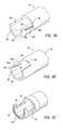
- FIG. 1illustrates a perspective view of an endocardial lead removing apparatus of a first embodiment of the present invention
- FIG. 2Aillustrates a perspective view of a distal end of an inner tubular member of the first embodiment of the present invention
- FIG. 2Billustrates a perspective view of a distal end of an outer tubular member of the first embodiment of the present invention
- FIG. 3Aillustrates a perspective view of the distal end of the inner tubular member of the first embodiment of the present invention having an angled cutting surface
- FIG. 3Billustrates a perspective view of the distal end of the outer tubular member of the first embodiment of the present invention having an angled cutting surface
- FIG. 3Cillustrates a first embodiment of the present invention having a T-shaped cutting channel
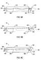
- FIG. 4illustrates a cross-sectional view along a longitudinal axis of a tubular member of an endocardial lead removing apparatus of another embodiment of the present invention
- FIG. 5illustrates a perspective view of the endocardial lead removing apparatus of an embodiment including an insert and adjustment mechanism
- FIGS. 6A-6Cillustrate a perspective view of an endocardial lead removing apparatus of another embodiment of the present invention
- FIG. 7illustrates an end view of the endocardial lead removing apparatus of one embodiment, without limitation
- FIGS. 8A-8Cillustrate a perspective view of an alternate embodiment of the endocardial lead removing apparatus of an embodiment having only one blade
- FIG. 9illustrates a perspective view of an endocardial lead removing apparatus of another embodiment of the present invention.
- FIGS. 10A-10Billustrate a perspective end view of the endocardial lead removing apparatus of one embodiment having teeth retracted and extended, respectively;
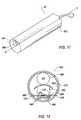
- FIG. 11illustrates a perspective view of an endocardial lead removing apparatus of a fifth embodiment of the present invention.
- FIG. 12illustrates a perspective end view of the endocardial lead removing apparatus of the fifth embodiment including a blade and adjustment mechanism.
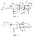
- FIGS. 13-14illustrate side cutaway perspectives of the endocardial lead removing apparatus of a sixth embodiment including movable and fixed cutting blades disposed at the distal end of the apparatus.
- an endocardial lead removing apparatusis generally referred to at 10 .
- the inventioncomprises an apparatus 10 that includes an outer tubular member 12 and an inner tubular member 14 .
- Each tubular member 12 , 14includes an inner cavity 16 .
- the inner tubular member 14is received within the inner cavity 16 of the outer tubular member 12 .
- Both of the members 12 , 14have distal ends 18 and proximal ends 20 with the proximal ends 20 of each member 12 , 14 having a handle 22 .
- the outer tubular member 12has a generally shorter length than the inner tubular member 14 and the handles 22 generally abut at the proximal ends 20 .
- the members 12 , 14are contemplated to be made of a metallic material such as hardened stainless steel; however other materials, such as rigid plastic, are also contemplated by the present invention.
- first and second channels 24 , 26are first and second channels 24 , 26 , respectively.
- the channels 24 , 26are generally L-shaped each having a longitudinal leg 28 and a lateral leg 30 .
- the lateral legs 30 of each channel 24 , 26are generally orthogonal to the longitudinal legs 28 .
- the first and second channels 24 , 26are opposed.
- the lateral legs 30 of each channel 24 , 26align and extend orthogonally from the longitudinal legs 28 in opposite directions.
- each of the channels 24 , 26includes at least one cutting surface 32 .
- the inventionalso comprises an inner tubular member 14 disposed in an outer tubular member 12 each with a T-shaped channel that forms a double blade with one or more cutting surfaces 32 on each member ( FIG. 3C ).
- the channels 24 , 26are bounded by a plurality of edges 34 .
- the lateral legs 30 of each channel 24 , 26are bounded by three edges 34 a , 34 b and 34 c .
- At least one of the three edges 34 a - cis the cutting surface 32 described above.
- the cutting surface 32is edge 34 b .
- the present embodimentcould include multiple cutting surfaces 32 such as each of the three edges 34 a - c .
- the edge 34 bmay be generally angled to improve cutting efficiency of the apparatus 10 .
- the first embodiment of apparatus 10 of FIGS. 1-3is inserted within a patient's chest cavity, blood vessel, or other anatomical part containing a lead (not shown) and receives a lead 100 (shown in phantom in FIG. 1 ) within the inner cavity 16 of the inner tubular member 14 .
- a lead 100shown in phantom in FIG. 1
- the lead 100is received within the channels 24 , 26 .
- Each of the tubular members 12 , 14are independently rotatable and when rotated in opposite directions the lead 100 is captured between the cutting surfaces 32 of each channel 24 , 26 . Additional torque applied to the handles 22 and further rotation of the members 12 , 14 cuts through the lead 100 .
- the severed portion of the lead 100remains within the inner cavity 16 of the inner tubular member 14 and the apparatus 10 is removed from the patient's body.
- FIGS. 4-5Another embodiment of the apparatus 10 is shown in FIGS. 4-5 .
- the embodimentincludes a tubular member 212 having a distal end 218 and a proximal end 220 .
- the tubular member 212is generally flexible and made from a polymer material. Further, the tubular member 212 may include reinforcements such as a braid or compressed coil (not shown) to strengthen the tubular member 212 and resist compression during operation.
- a metallic wire 236Disposed within an inner cavity 216 of the tubular member 212 is a metallic wire 236 .
- a filament or strong cord, optionally diamond-coated, or other element suitable for cuttingmay be substituted for the metallic wire.
- the metallic wire 236has opposite ends 238 extending from the proximal end 220 of the tubular member 212 .
- the opposite ends 238 of the metallic wire 236include handles 222 .
- the metallic wire 236extends through the inner cavity 216 and outwardly at the distal end 218 thereby forming a loop 240 . It is contemplated that the metallic wire 236 is made from stainless steel or nickel titanium and has a diameter of about 0.005 inches to about 0.030 inches; however, other materials and diameters are also contemplated by the present invention.
- the lumen 242is disposed within the inner cavity 216 of the tubular member 212 .
- the lumencould be a second polymer lumen, even include a lubricious sleeve (such as polytetrafluoroethelene (PTFE) or FEP).
- the lumen 242may be made from a flexible material such as nickel titanium, although other materials are also contemplated.
- the lumen 242is disposed at one side of the inner cavity 216 .
- the lumen 242extends the length of the tubular member 212 and when only one lumen 242 is contemplated the opposite ends 238 of the metallic wire 236 are both disposed therein.
- two lumen 242one for each opposite end 238 of the metallic wire 236 , may be positioned adjacent to each other at one side of the inner cavity 216 of the tubular member 212 .
- the inventionalso comprises an adjustment mechanism 246 ( FIG. 5 ).
- the adjustment mechanism 246moves the opposite ends 238 of the metallic wire 236 to reduce or expand the size of the loop 240 .
- the adjustment mechanism 246includes a rotatable pin 248 disposed within the inner cavity 216 at one side, optionally within a catheter 242 .
- One of the opposite ends 238 of the metallic wire 236is fixed to the rotatable pin 248 .
- the second of the opposite ends 238is fixed to a tension mechanism 250 such as a spring and the like.
- a handle 222is disposed at a proximal end 220 to rotate the rotatable pin 248 and wind the metallic wire 236 thereabout.
- the apparatus 10 of FIG. 4includes the metallic wire 236 extending at the distal end 218 of the tubular member 212 to form the loop 240 .
- the apparatus 10is inserted within a patient and positioned near the lead 100 .
- the free end of the lead 100is received within the inner cavity 216 of the tubular member 212 and extends outwardly at the distal end 218 and through the loop 240 .
- the opposite ends 238 of the metallic wire 236are moveable to reduce the size of the loop 240 .
- the metallic wire 236is disposed in a single lumen 242 or two adjacent lumen 242 , as illustrated in FIG. 4 , the opposite ends 238 are simply pulled through the tubular member 212 and the loop 240 is reduced in size. Accordingly the metallic wire 236 of the loop 240 slices through the lead 100 .
- the severed portion of the lead 100remains within the inner cavity 216 of the tubular member 212 and the apparatus is removed from the patient.
- two separate lumens 242are employed and the adjustment mechanism 246 is utilized.
- One lumenis preferably adjacent or nearly so.
- the lead 100is received in the inner cavity 216 and extends outwardly at the distal end 218 and through the loop 240 .
- the adjustment mechanism 246is actuated by rotating the rotatable pin 248 , preferably using handle 220 . Accordingly, one of the opposite ends 238 is wound around the rotatable pin 248 and the size of the loop 240 is reduced.
- the lead 100is captured between the insert 244 and the loop 240 .
- the cutting surface 232 of the insert 244 and the metallic wire 236 of the loop 240slice through the lead 100 .
- the severed portion of the lead 100remains within the inner cavity 216 of the tubular member 212 and the apparatus 10 is removed from the patient.
- the apparatus 10includes a tubular member 312 having a distal end 318 and a proximal end 320 .
- the tubular member 312is preferably a metal coil shaft to allow for flexibility while resisting compression during operations.
- any materialis contemplated by the present invention.
- At least one blade 352is pivotally connected to the distal end 318 of the tubular member 312 . As seen in FIGS. 6A-6C , two blades 352 are pivotally connected at the distal end 318 by a pivot pin 354 . Each of the blades 352 is generally arcuate to define a cutting surface 332 . Further, the blades 352 are moveable between a retracted position ( FIG. 6A ) and an extended position ( FIGS. 6B-6C ).
- the apparatus 10includes only one blade 352 .
- the blade 352is pivotally connected at the distal end 318 by the pivot pin 354 .
- the blade 352is generally arcuate to define an inner cutting surface 332 .
- the distal end 318 of the tubular member 312is generally angled and defines a second cutting surface 332 .
- the blade 352is moveable between the retracted position ( FIG. 8A ) and the extended position ( FIGS. 8B-8C ).
- the apparatus 10 of another embodimentfurther includes an adjustment mechanism 346 .
- the adjustment mechanism 246pivots the blade(s) 352 between the retracted and extended positions.
- the adjustment mechanism 346may include an outer sheath (not shown) that receives the tubular member 312 and is moveable longitudinally along the tubular member 312 . A distal end of the outer sheath generally aligns with the distal end 318 of the tubular member 312 and engages the blade(s) 352 . Continued longitudinal movement of the outer sheath urges the blades(s) 352 about the pivot pin 354 to pivot from the retracted to the extended position.
- the adjustment mechanism 346includes a pull wire 356 .
- the pull wire 356is attached to the blade(s) 352 and extends within an inner cavity 316 of the tubular member 312 .
- a proximal end of the pull wire 356is preferably joined to a handle 322 .
- the embodiment of apparatus 10 of FIGS. 6-8is inserted within a patient's heart or other anatomical part containing a lead and receives the lead 100 within the inner cavity 316 of the tubular member 312 .
- the adjustment mechanism 346is actuated. As shown, tension is applied to the pull wire 356 , preferably at the handle 322 , and the blade(s) 352 pivot about the pivot pin 354 .
- the lead 100is captured between the cutting surfaces 332 of the two blades 352 ( FIGS. 6A-6C ).
- the lead 100is captured between the cutting surface 332 of the one blade 352 and the cutting surface 332 of the distal end 318 of the tubular member 312 ( FIGS. 8A-8C ). Additional tension is applied to the pull wire 356 and the cutting surfaces 332 cut through the lead 100 . The severed portion of the lead 100 remains within the inner cavity 316 of the tubular member 312 and the apparatus 10 is removed from the patient's body.
- the apparatus 10includes a tubular member 412 having a distal end 418 and a proximal end 420 .
- the tubular member 412defines a longitudinal axis A-A and an inner cavity 416 .
- the tubular member 412is generally flexible and is preferably made from a plastic or polymer material. However, any material is contemplated by the present invention.
- At least one tooth 458is generally positioned at the distal end 418 of the tubular member 412 within the inner cavity 416 .
- the tubular member 412includes a tubular wall 460 defining the inner cavity 416 .
- the tooth 458connects to the tubular wall 460 .
- the at least one tooth 458includes a plurality of edges 462 and at least one of the edges 462 is a cutting surface 432 .
- this embodiment of the apparatus 10comprises four teeth 458 .
- the present inventioncontemplates a plurality of teeth 458 or even only one tooth 458 .
- the four teeth 458 of the illustrated embodimentare generally triangular; however, the present invention also contemplates asymmetrically shaped teeth 458 .
- the teeth 458 of this embodimentare moveable between a retracted position and an extended position.
- the retracted positionpositions the teeth 458 generally parallel to the tubular wall 460 of the tubular member 412 .
- the extended positionpositions the teeth 458 generally orthogonal to the tubular wall 460 of the tubular member 412 . Accordingly, when the teeth 458 are in the extended position the tubular member 412 has a reduced inner diameter.
- a hinge mechanism 464connects the teeth 458 to the tubular wall 460 of the tubular member 412 .
- the hinge mechanism 464adjusts the teeth 458 between the retracted position and the extended position to place the cutting surfaces 432 of the teeth 458 in contact with the lead 100 .
- the apparatus 10may include an actuator (not shown) for adjusting the teeth 458 between the positions. Otherwise, the movement of the teeth 458 between the positions is manually actuated by a handle 422 at the proximal end 420 of the tubular member 412 .
- this embodiment of apparatus 10is inserted within a patient's heart or other anatomical part containing a lead and positioned near the embedded electrode tip.
- the free end of the lead 100is received within the inner cavity 416 of the tubular member 412 .
- the teeth 458are in the retracted position and generally parallel to the tubular wall 460 .
- the tubular member 412is retracted. Extension and retraction of the tubular member 412 is facilitated by the handle 422 at the proximal end 420 .
- the apparatus 10includes a tubular member 512 defining a tubular wall 560 and a longitudinal axis A-A.
- the tubular member 512is generally flexible and made from a plastic or polymer material; however, any material is contemplated by the present invention.
- the tubular member 512 and tubular wall 560define an inner cavity 516 .
- the inner cavity 516is generally offset from the longitudinal axis A-A of the tubular member 512 in order to accommodate a blade 552 and adjustment mechanism 546 within the tubular wall 560 .
- the apparatus 10includes the blade 552 disposed within the tubular wall 560 of the tubular member 512 .
- the blade 552by way of the adjustment mechanism 546 , is moveable between a retracted position and an extended position. Further, the blade 552 includes a generally arcuate cutting surface 532 .
- the adjustment mechanism 546 of the fifth embodimentis pneumatically actuated.
- the adjustment mechanism 546includes an inflatable device 566 , such as a balloon and the like.
- the inflatable device 566is disposed within the tubular wall 560 and placed adjacent the blade 552 at an end opposite the cutting surface 532 . Expansion and retraction of the inflatable device 566 expands or retracts the cutting surface 532 of the blade 552 into the inner cavity 516 of the tubular member.
- the adjustment mechanism 546includes a guide comprising of two projecting arms 568 and a track 570 .
- the guidefacilitates movement of the blade 552 between the retracted and extended positions to insert the cutting surface 532 into the inner cavity 516 .
- the blade 552is adapted to receive first ends 572 of each of the projecting arms 568 .
- the bladeincludes a notch 574 . Received within the notch 574 are the first ends 572 of the projecting arms 568 .
- the projection arms 568are generally parallel to the cutting surface 532 of the blade 552 .
- the projecting arms 568slide within the notch 574 . Second ends 576 of the projecting arms 568 are received within the track 570 .
- the track 570is disposed within the tubular wall 560 and extends circumferentially about the tubular member 512 .
- the fifth embodiment of apparatus 10 of FIGS. 11-12is inserted within a patient's heart or other anatomical part containing a lead and positioned as near as possible to the electrode tip embedded within the body.
- the free end of the lead 100is received within the inner cavity 516 of the tubular member 512 .
- Airis supplied through a catheter (not shown) to the inflatable device 566 or balloon.
- the inflatable device 566expands thereby urging the blade 552 from the retracted position to the expanded position and inserting the cutting surface 532 of the blade 552 into the inner cavity 516 .
- the blade 552moves from the retracted position to the expanded position the second ends 576 of the projecting arms 568 move along the track 570 sliding within the notch 574 as appropriate, to accommodate the varying width of the inner cavity 516 .
- the cutting surface 532 of the blade 552cuts through the lead 100 . Once severed, the cut portion of the lead 100 remains within the inner cavity 516 and the apparatus 10 is removed from the patient.
- the apparatus 10includes a tubular member 612 defining a tubular wall 660 .
- the tubular member 612is generally flexible and made from a plastic or polymer material; however, any material is contemplated by the present invention.
- the tubular member 612 and tubular wall 660define an inner cavity 616 .
- the distal end 618 of the tubular member 612tapers outwardly to an increased diameter portion 620 and is configured to include a cutting blade 622 .
- the cutting blade 622is cylindrical in shape with a lumen 623 configured to accept an endocardial lead 626 or other object for cutting.
- the cutting bladeis movably disposed within the inner cavity 616 of the tubular member 612 .
- the proximal end of the cutting bladehas a diameter greater than the smallest diameter of the taper so that, in operation, the taper limits the longitudinal travel of the cutting blade 622 in the proximal direction.
- the distal end of the tubular member 612is formed to retain the cutting blade within the inner cavity 616 , as one example only and without limitation, by an inwardly turned ridge 624 at the distal end 618 .
- the tubular wall 612 of the increased diameter portion 620has an opening 624 that permits exchange between the inner cavity 616 and the space exterior to the apparatus.
- the opening 624is configured to receive an endocardial lead 626 or other object for cutting.
- the opening 624may be any suitable size or shape, although a round or oval shape is preferred. In some preferred embodiments, without limitation, the opening is about 0.200′′-0.250′′ from the distal end and is configured to be large enough to accept leads between from about 0.070′′ to about 0.170′′ in diameter.
- the apparatusis comprised of at least one cutting edge, although it may also have at least two such edges.
- the most proximal inner surface of the openingmay optionally be comprised of a cutting edge 628 .
- the cutting edgemay be beveled.
- the cutting blade 622is operably attached to a pull wire 630 that extends longitudinally within the inner cavity of the apparatus to at least the proximal end of the tubular member.
- the pull wire 630is fixedly attached to the cutting blade 622 by soldering or other methods known to those of ordinary skill in the art.
- the proximal edge of the cutting blade 622may optionally be comprised of a cutting edge 632 .
- the cutting edgemay be beveled.
- the sixth embodiment of apparatus 10 of FIGS. 13-14is threaded over the most proximal end of the lead 626 by inserting the lead within the open distal end of the tubular member 612 and through the opening 624 in the side wall of the increased diameter portion 620 of the apparatus.
- the apparatusmay then be further inserted within the patient by advancing the apparatus over the lead to the desired location for severing the lead.
- the pull wire 630is activated by pulling it longitudinally in the proximal direction. As the pull wire is activated, the cutting blade 622 connected to the pull wire is also moved in the proximal direction.
- the cutting bladeAs the cutting blade moves proximally, it contacts the lead near a point where the lead exits the opening 624 in the side wall of the tubular member. As the cutting blade moves proximally, it also forces an opposing side of the lead 626 into contact with the proximal cutting edge 628 disposed on the inner surface of the opening 624 in the side wall. Continued activation of the pull wire causes the cutting edge 628 of the opening 624 and the second cutting edge 632 of the cutting blade 622 to cut through the lead. The tapered shoulder at the proximal end of the increased diameter portion 620 limits the proximal movement of the cutting blade 622 as the pull wire 630 is activated. Once severed, the proximal portion of the lead and the apparatus are removed from the patient, either separately or together.
Landscapes
- Health & Medical Sciences (AREA)
- Life Sciences & Earth Sciences (AREA)
- Heart & Thoracic Surgery (AREA)
- Surgery (AREA)
- Veterinary Medicine (AREA)
- Public Health (AREA)
- Engineering & Computer Science (AREA)
- Nuclear Medicine, Radiotherapy & Molecular Imaging (AREA)
- Biomedical Technology (AREA)
- Animal Behavior & Ethology (AREA)
- General Health & Medical Sciences (AREA)
- Molecular Biology (AREA)
- Medical Informatics (AREA)
- Orthopedic Medicine & Surgery (AREA)
- Vascular Medicine (AREA)
- Cardiology (AREA)
- Radiology & Medical Imaging (AREA)
- Surgical Instruments (AREA)
Abstract
Description
Claims (7)
Priority Applications (3)
| Application Number | Priority Date | Filing Date | Title |
|---|---|---|---|
| US11/484,825US7993359B1 (en) | 2005-07-27 | 2006-07-11 | Endocardial lead removing apparatus |
| PCT/US2006/028960WO2007016141A2 (en) | 2005-07-27 | 2006-07-25 | Endocardial lead removing apparatus |
| EP06788509.5AEP1909660B1 (en) | 2005-07-27 | 2006-07-25 | Endocardial lead removing apparatus |
Applications Claiming Priority (2)
| Application Number | Priority Date | Filing Date | Title |
|---|---|---|---|
| US11/190,550US8097012B2 (en) | 2005-07-27 | 2005-07-27 | Endocardial lead removing apparatus |
| US11/484,825US7993359B1 (en) | 2005-07-27 | 2006-07-11 | Endocardial lead removing apparatus |
Related Parent Applications (1)
| Application Number | Title | Priority Date | Filing Date |
|---|---|---|---|
| US11/190,550Continuation-In-PartUS8097012B2 (en) | 2005-07-27 | 2005-07-27 | Endocardial lead removing apparatus |
Publications (1)
| Publication Number | Publication Date |
|---|---|
| US7993359B1true US7993359B1 (en) | 2011-08-09 |
Family
ID=37709134
Family Applications (1)
| Application Number | Title | Priority Date | Filing Date |
|---|---|---|---|
| US11/484,825Expired - Fee RelatedUS7993359B1 (en) | 2005-07-27 | 2006-07-11 | Endocardial lead removing apparatus |
Country Status (3)
| Country | Link |
|---|---|
| US (1) | US7993359B1 (en) |
| EP (1) | EP1909660B1 (en) |
| WO (1) | WO2007016141A2 (en) |
Cited By (33)
| Publication number | Priority date | Publication date | Assignee | Title |
|---|---|---|---|---|
| US20110208207A1 (en)* | 2005-07-27 | 2011-08-25 | Bowe Wade A | Endocardial lead removing apparatus |
| US20140276926A1 (en)* | 2013-03-13 | 2014-09-18 | The Spectranetics Corporation | Stabilization device assisted lead tip removal |
| US8961551B2 (en) | 2006-12-22 | 2015-02-24 | The Spectranetics Corporation | Retractable separating systems and methods |
| US9028520B2 (en) | 2006-12-22 | 2015-05-12 | The Spectranetics Corporation | Tissue separating systems and methods |
| US9283040B2 (en) | 2013-03-13 | 2016-03-15 | The Spectranetics Corporation | Device and method of ablative cutting with helical tip |
| US9291663B2 (en) | 2013-03-13 | 2016-03-22 | The Spectranetics Corporation | Alarm for lead insulation abnormality |
| US9413896B2 (en) | 2012-09-14 | 2016-08-09 | The Spectranetics Corporation | Tissue slitting methods and systems |
| USD765243S1 (en) | 2015-02-20 | 2016-08-30 | The Spectranetics Corporation | Medical device handle |
| US9456872B2 (en) | 2013-03-13 | 2016-10-04 | The Spectranetics Corporation | Laser ablation catheter |
| USD770616S1 (en) | 2015-02-20 | 2016-11-01 | The Spectranetics Corporation | Medical device handle |
| US9603618B2 (en) | 2013-03-15 | 2017-03-28 | The Spectranetics Corporation | Medical device for removing an implanted object |
| US9668765B2 (en) | 2013-03-15 | 2017-06-06 | The Spectranetics Corporation | Retractable blade for lead removal device |
| US9731113B2 (en) | 2014-12-30 | 2017-08-15 | The Spectranetics Corporation | Collapsing coil coupling for lead extension and extraction |
| US9883885B2 (en) | 2013-03-13 | 2018-02-06 | The Spectranetics Corporation | System and method of ablative cutting and pulsed vacuum aspiration |
| US9884184B2 (en) | 2014-12-30 | 2018-02-06 | The Spectranetics Corporation | Wire hook coupling for lead extension and extraction |
| US9918729B2 (en) | 2009-09-14 | 2018-03-20 | The Spectranetics Corporation | Snaring systems and methods |
| US9925366B2 (en) | 2013-03-15 | 2018-03-27 | The Spectranetics Corporation | Surgical instrument for removing an implanted object |
| US9980743B2 (en) | 2013-03-15 | 2018-05-29 | The Spectranetics Corporation | Medical device for removing an implanted object using laser cut hypotubes |
| US10105533B2 (en) | 2014-12-30 | 2018-10-23 | The Spectranetics Corporation | Multi-loop coupling for lead extension and extraction |
| US10136913B2 (en) | 2013-03-15 | 2018-11-27 | The Spectranetics Corporation | Multiple configuration surgical cutting device |
| US10258792B2 (en) | 2005-07-22 | 2019-04-16 | The Spectranetics Corporation | Endocardial lead cutting apparatus |
| US10383691B2 (en) | 2013-03-13 | 2019-08-20 | The Spectranetics Corporation | Last catheter with helical internal lumen |
| US10405924B2 (en) | 2014-05-30 | 2019-09-10 | The Spectranetics Corporation | System and method of ablative cutting and vacuum aspiration through primary orifice and auxiliary side port |
| US10448999B2 (en) | 2013-03-15 | 2019-10-22 | The Spectranetics Corporation | Surgical instrument for removing an implanted object |
| US10772683B2 (en) | 2014-05-18 | 2020-09-15 | Eximo Medical Ltd. | System for tissue ablation using pulsed laser |
| US10835279B2 (en) | 2013-03-14 | 2020-11-17 | Spectranetics Llc | Distal end supported tissue slitting apparatus |
| US10842532B2 (en) | 2013-03-15 | 2020-11-24 | Spectranetics Llc | Medical device for removing an implanted object |
| US11357977B2 (en) | 2014-12-30 | 2022-06-14 | Spectranetics Llc | Expanding coil coupling for lead extension and extraction |
| US11576724B2 (en) | 2011-02-24 | 2023-02-14 | Eximo Medical Ltd. | Hybrid catheter for vascular intervention |
| US11684420B2 (en) | 2016-05-05 | 2023-06-27 | Eximo Medical Ltd. | Apparatus and methods for resecting and/or ablating an undesired tissue |
| US12038322B2 (en) | 2022-06-21 | 2024-07-16 | Eximo Medical Ltd. | Devices and methods for testing ablation systems |
| US12053203B2 (en) | 2014-03-03 | 2024-08-06 | Spectranetics, Llc | Multiple configuration surgical cutting device |
| US12376904B1 (en) | 2020-09-08 | 2025-08-05 | Angiodynamics, Inc. | Dynamic laser stabilization and calibration system |
Families Citing this family (10)
| Publication number | Priority date | Publication date | Assignee | Title |
|---|---|---|---|---|
| US9943392B2 (en)* | 2011-05-04 | 2018-04-17 | Boston Scientific Scimed, Inc. | Implants, tools, and methods for treatment of pelvic conditions |
| WO2016044072A1 (en) | 2014-09-18 | 2016-03-24 | Mayo Foundation For Medical Education And Research | Soft tissue cutting device and methods of use |
| EP4324417A3 (en)* | 2015-10-14 | 2024-03-20 | Corinth Medtech, Inc. | Surgical device and method of use |
| US10864055B2 (en) | 2017-10-13 | 2020-12-15 | Sonex Health, Inc. | Tray for a soft tissue cutting device and methods of use |
| EP3908215B1 (en) | 2019-01-11 | 2023-08-02 | Mayo Foundation for Medical Education and Research | Micro-invasive surgical device |
| US12426939B2 (en) | 2019-05-29 | 2025-09-30 | Mayo Foundation For Medical Education And Research | Micro-invasive surgical device and methods of use |
| WO2022150837A1 (en) | 2021-01-08 | 2022-07-14 | Sonex Health, Inc. | Surgical cutting device for ultrasonic guided soft tissue surgery |
| US12251122B2 (en) | 2021-04-30 | 2025-03-18 | Sonex Health, Inc. | Cutting device for trigger finger and other soft tissues |
| USD989961S1 (en) | 2021-04-30 | 2023-06-20 | Sonex Health, Inc. | Soft tissue cutting device |
| CN116407182A (en)* | 2021-12-31 | 2023-07-11 | 杭州德诺电生理医疗科技有限公司 | Thread cutting device |
Citations (11)
| Publication number | Priority date | Publication date | Assignee | Title |
|---|---|---|---|---|
| US5171314A (en)* | 1990-07-24 | 1992-12-15 | Andrew Surgical, Inc. | Surgical snare |
| US5474532A (en) | 1994-11-22 | 1995-12-12 | Alcon Laboratories, Inc. | Cutting blade for a vitreous cutter |
| US5665062A (en)* | 1995-01-23 | 1997-09-09 | Houser; Russell A. | Atherectomy catheter and RF cutting method |
| US5863294A (en) | 1996-01-26 | 1999-01-26 | Femrx, Inc. | Folded-end surgical tubular cutter and method for fabrication |
| US6139508A (en) | 1998-08-04 | 2000-10-31 | Endonetics, Inc. | Articulated medical device |
| US6419684B1 (en) | 2000-05-16 | 2002-07-16 | Linvatec Corporation | End-cutting shaver blade for axial resection |
| US6432115B1 (en) | 1999-04-05 | 2002-08-13 | Starion Instruments Corporation | Suture welding device |
| US6447525B2 (en) | 1999-08-19 | 2002-09-10 | Fox Hollow Technologies, Inc. | Apparatus and methods for removing material from a body lumen |
| WO2003022157A2 (en) | 2001-09-12 | 2003-03-20 | Manoa Medical, Inc. | Devices and methods for tissue severing and removal |
| US20030078609A1 (en) | 1999-08-30 | 2003-04-24 | Finlay Russell L. | Method of operating microsurgical instruments |
| WO2004073524A1 (en) | 2003-02-20 | 2004-09-02 | Manoa Medical, Inc. | Bendable cutting device |
Family Cites Families (5)
| Publication number | Priority date | Publication date | Assignee | Title |
|---|---|---|---|---|
| US4274414A (en)* | 1979-02-21 | 1981-06-23 | Dyonics, Inc. | Surgical instrument |
| US5779715A (en)* | 1997-07-28 | 1998-07-14 | Irvine Biomedical, Inc. | Lead extraction system and methods thereof |
| US6033402A (en)* | 1998-09-28 | 2000-03-07 | Irvine Biomedical, Inc. | Ablation device for lead extraction and methods thereof |
| US6428539B1 (en)* | 2000-03-09 | 2002-08-06 | Origin Medsystems, Inc. | Apparatus and method for minimally invasive surgery using rotational cutting tool |
| US7651504B2 (en)* | 2003-02-05 | 2010-01-26 | Cook Vascular Incorporated | Device for removing an elongated structure implanted in biological tissue |
- 2006
- 2006-07-11USUS11/484,825patent/US7993359B1/ennot_activeExpired - Fee Related
- 2006-07-25EPEP06788509.5Apatent/EP1909660B1/ennot_activeNot-in-force
- 2006-07-25WOPCT/US2006/028960patent/WO2007016141A2/enactiveApplication Filing
Patent Citations (11)
| Publication number | Priority date | Publication date | Assignee | Title |
|---|---|---|---|---|
| US5171314A (en)* | 1990-07-24 | 1992-12-15 | Andrew Surgical, Inc. | Surgical snare |
| US5474532A (en) | 1994-11-22 | 1995-12-12 | Alcon Laboratories, Inc. | Cutting blade for a vitreous cutter |
| US5665062A (en)* | 1995-01-23 | 1997-09-09 | Houser; Russell A. | Atherectomy catheter and RF cutting method |
| US5863294A (en) | 1996-01-26 | 1999-01-26 | Femrx, Inc. | Folded-end surgical tubular cutter and method for fabrication |
| US6139508A (en) | 1998-08-04 | 2000-10-31 | Endonetics, Inc. | Articulated medical device |
| US6432115B1 (en) | 1999-04-05 | 2002-08-13 | Starion Instruments Corporation | Suture welding device |
| US6447525B2 (en) | 1999-08-19 | 2002-09-10 | Fox Hollow Technologies, Inc. | Apparatus and methods for removing material from a body lumen |
| US20030078609A1 (en) | 1999-08-30 | 2003-04-24 | Finlay Russell L. | Method of operating microsurgical instruments |
| US6419684B1 (en) | 2000-05-16 | 2002-07-16 | Linvatec Corporation | End-cutting shaver blade for axial resection |
| WO2003022157A2 (en) | 2001-09-12 | 2003-03-20 | Manoa Medical, Inc. | Devices and methods for tissue severing and removal |
| WO2004073524A1 (en) | 2003-02-20 | 2004-09-02 | Manoa Medical, Inc. | Bendable cutting device |
Cited By (73)
| Publication number | Priority date | Publication date | Assignee | Title |
|---|---|---|---|---|
| US10258792B2 (en) | 2005-07-22 | 2019-04-16 | The Spectranetics Corporation | Endocardial lead cutting apparatus |
| US20110208207A1 (en)* | 2005-07-27 | 2011-08-25 | Bowe Wade A | Endocardial lead removing apparatus |
| US8097012B2 (en) | 2005-07-27 | 2012-01-17 | The Spectranetics Corporation | Endocardial lead removing apparatus |
| US10537354B2 (en) | 2006-12-22 | 2020-01-21 | The Spectranetics Corporation | Retractable separating systems and methods |
| US10869687B2 (en) | 2006-12-22 | 2020-12-22 | Spectranetics Llc | Tissue separating systems and methods |
| US9289226B2 (en) | 2006-12-22 | 2016-03-22 | The Spectranetics Corporation | Retractable separating systems and methods |
| US9801650B2 (en) | 2006-12-22 | 2017-10-31 | The Spectranetics Corporation | Tissue separating systems and methods |
| US9808275B2 (en) | 2006-12-22 | 2017-11-07 | The Spectranetics Corporation | Retractable separating systems and methods |
| US9028520B2 (en) | 2006-12-22 | 2015-05-12 | The Spectranetics Corporation | Tissue separating systems and methods |
| US8961551B2 (en) | 2006-12-22 | 2015-02-24 | The Spectranetics Corporation | Retractable separating systems and methods |
| US10687836B2 (en) | 2009-09-14 | 2020-06-23 | Spectranetics Llc | Snaring systems and methods |
| US9918729B2 (en) | 2009-09-14 | 2018-03-20 | The Spectranetics Corporation | Snaring systems and methods |
| US12042223B2 (en) | 2011-02-24 | 2024-07-23 | Eximo Medical Ltd. | Hybrid catheter for vascular intervention |
| US11576724B2 (en) | 2011-02-24 | 2023-02-14 | Eximo Medical Ltd. | Hybrid catheter for vascular intervention |
| US9413896B2 (en) | 2012-09-14 | 2016-08-09 | The Spectranetics Corporation | Tissue slitting methods and systems |
| US9724122B2 (en) | 2012-09-14 | 2017-08-08 | The Spectranetics Corporation | Expandable lead jacket |
| US11596435B2 (en) | 2012-09-14 | 2023-03-07 | Specrtranetics Llc | Tissue slitting methods and systems |
| US9763692B2 (en) | 2012-09-14 | 2017-09-19 | The Spectranetics Corporation | Tissue slitting methods and systems |
| US10531891B2 (en) | 2012-09-14 | 2020-01-14 | The Spectranetics Corporation | Tissue slitting methods and systems |
| US9949753B2 (en) | 2012-09-14 | 2018-04-24 | The Spectranetics Corporation | Tissue slitting methods and systems |
| US10368900B2 (en) | 2012-09-14 | 2019-08-06 | The Spectranetics Corporation | Tissue slitting methods and systems |
| US9456872B2 (en) | 2013-03-13 | 2016-10-04 | The Spectranetics Corporation | Laser ablation catheter |
| US10799293B2 (en) | 2013-03-13 | 2020-10-13 | The Spectranetics Corporation | Laser ablation catheter |
| US9883885B2 (en) | 2013-03-13 | 2018-02-06 | The Spectranetics Corporation | System and method of ablative cutting and pulsed vacuum aspiration |
| US20140276926A1 (en)* | 2013-03-13 | 2014-09-18 | The Spectranetics Corporation | Stabilization device assisted lead tip removal |
| US9925371B2 (en) | 2013-03-13 | 2018-03-27 | The Spectranetics Corporation | Alarm for lead insulation abnormality |
| US9421035B2 (en)* | 2013-03-13 | 2016-08-23 | The Spectranetics Corporation | Method for lead tip removal using a stabilization device |
| US9937005B2 (en) | 2013-03-13 | 2018-04-10 | The Spectranetics Corporation | Device and method of ablative cutting with helical tip |
| US9291663B2 (en) | 2013-03-13 | 2016-03-22 | The Spectranetics Corporation | Alarm for lead insulation abnormality |
| US10485613B2 (en) | 2013-03-13 | 2019-11-26 | The Spectranetics Corporation | Device and method of ablative cutting with helical tip |
| US10383691B2 (en) | 2013-03-13 | 2019-08-20 | The Spectranetics Corporation | Last catheter with helical internal lumen |
| US9283040B2 (en) | 2013-03-13 | 2016-03-15 | The Spectranetics Corporation | Device and method of ablative cutting with helical tip |
| US10039569B2 (en) | 2013-03-13 | 2018-08-07 | The Spectranetics Corporation | Stabilization device assisted lead tip removal |
| US10265520B2 (en) | 2013-03-13 | 2019-04-23 | The Spetranetics Corporation | Alarm for lead insulation abnormality |
| US10835279B2 (en) | 2013-03-14 | 2020-11-17 | Spectranetics Llc | Distal end supported tissue slitting apparatus |
| US11925380B2 (en) | 2013-03-14 | 2024-03-12 | Spectranetics Llc | Distal end supported tissue slitting apparatus |
| US10448999B2 (en) | 2013-03-15 | 2019-10-22 | The Spectranetics Corporation | Surgical instrument for removing an implanted object |
| US10524817B2 (en) | 2013-03-15 | 2020-01-07 | The Spectranetics Corporation | Surgical instrument including an inwardly deflecting cutting tip for removing an implanted object |
| US10052129B2 (en) | 2013-03-15 | 2018-08-21 | The Spectranetics Corporation | Medical device for removing an implanted object |
| US10314615B2 (en) | 2013-03-15 | 2019-06-11 | The Spectranetics Corporation | Medical device for removing an implanted object |
| US11925334B2 (en) | 2013-03-15 | 2024-03-12 | Spectranetics Llc | Surgical instrument for removing an implanted object |
| US10219819B2 (en) | 2013-03-15 | 2019-03-05 | The Spectranetics Corporation | Retractable blade for lead removal device |
| US9980743B2 (en) | 2013-03-15 | 2018-05-29 | The Spectranetics Corporation | Medical device for removing an implanted object using laser cut hypotubes |
| US9603618B2 (en) | 2013-03-15 | 2017-03-28 | The Spectranetics Corporation | Medical device for removing an implanted object |
| US10849603B2 (en) | 2013-03-15 | 2020-12-01 | Spectranetics Llc | Surgical instrument for removing an implanted object |
| US9668765B2 (en) | 2013-03-15 | 2017-06-06 | The Spectranetics Corporation | Retractable blade for lead removal device |
| US10842532B2 (en) | 2013-03-15 | 2020-11-24 | Spectranetics Llc | Medical device for removing an implanted object |
| US9925366B2 (en) | 2013-03-15 | 2018-03-27 | The Spectranetics Corporation | Surgical instrument for removing an implanted object |
| US9956399B2 (en) | 2013-03-15 | 2018-05-01 | The Spectranetics Corporation | Medical device for removing an implanted object |
| US9918737B2 (en) | 2013-03-15 | 2018-03-20 | The Spectranetics Corporation | Medical device for removing an implanted object |
| US10136913B2 (en) | 2013-03-15 | 2018-11-27 | The Spectranetics Corporation | Multiple configuration surgical cutting device |
| US11160579B2 (en) | 2013-03-15 | 2021-11-02 | Spectranetics Llc | Multiple configuration surgical cutting device |
| US12053203B2 (en) | 2014-03-03 | 2024-08-06 | Spectranetics, Llc | Multiple configuration surgical cutting device |
| US10792103B2 (en) | 2014-05-18 | 2020-10-06 | Eximo Medical Ltd. | System for tissue ablation using pulsed laser |
| US10772683B2 (en) | 2014-05-18 | 2020-09-15 | Eximo Medical Ltd. | System for tissue ablation using pulsed laser |
| US11116573B2 (en) | 2014-05-18 | 2021-09-14 | Eximo Medical Ltd | System for tissue ablation using pulsed laser |
| US10405924B2 (en) | 2014-05-30 | 2019-09-10 | The Spectranetics Corporation | System and method of ablative cutting and vacuum aspiration through primary orifice and auxiliary side port |
| US11357977B2 (en) | 2014-12-30 | 2022-06-14 | Spectranetics Llc | Expanding coil coupling for lead extension and extraction |
| US11826563B2 (en) | 2014-12-30 | 2023-11-28 | Koninklijke Philips N.V. | Expanding tube coupling for reversible lead locking |
| US9731113B2 (en) | 2014-12-30 | 2017-08-15 | The Spectranetics Corporation | Collapsing coil coupling for lead extension and extraction |
| US10105533B2 (en) | 2014-12-30 | 2018-10-23 | The Spectranetics Corporation | Multi-loop coupling for lead extension and extraction |
| US11173298B2 (en) | 2014-12-30 | 2021-11-16 | Spectranetics Llc. | Collapsing coil coupling for lead extension and extraction |
| US9884184B2 (en) | 2014-12-30 | 2018-02-06 | The Spectranetics Corporation | Wire hook coupling for lead extension and extraction |
| US10391300B2 (en) | 2014-12-30 | 2019-08-27 | The Spectranetics Corporation | Collapsing coil coupling for lead extension and extraction |
| US10864370B2 (en) | 2014-12-30 | 2020-12-15 | Koninklijke Philips N.V. | Multi-loop coupling for lead extension and extraction |
| USD770616S1 (en) | 2015-02-20 | 2016-11-01 | The Spectranetics Corporation | Medical device handle |
| USD819204S1 (en) | 2015-02-20 | 2018-05-29 | The Spectranetics Corporation | Medical device handle |
| USD854682S1 (en) | 2015-02-20 | 2019-07-23 | The Spectranetics Corporation | Medical device handle |
| USD765243S1 (en) | 2015-02-20 | 2016-08-30 | The Spectranetics Corporation | Medical device handle |
| USD806245S1 (en) | 2015-02-20 | 2017-12-26 | The Spectranetics Corporation | Medical device handle |
| US11684420B2 (en) | 2016-05-05 | 2023-06-27 | Eximo Medical Ltd. | Apparatus and methods for resecting and/or ablating an undesired tissue |
| US12376904B1 (en) | 2020-09-08 | 2025-08-05 | Angiodynamics, Inc. | Dynamic laser stabilization and calibration system |
| US12038322B2 (en) | 2022-06-21 | 2024-07-16 | Eximo Medical Ltd. | Devices and methods for testing ablation systems |
Also Published As
| Publication number | Publication date |
|---|---|
| WO2007016141A3 (en) | 2007-06-28 |
| EP1909660A4 (en) | 2013-04-17 |
| WO2007016141A2 (en) | 2007-02-08 |
| EP1909660A2 (en) | 2008-04-16 |
| EP1909660B1 (en) | 2018-05-23 |
Similar Documents
| Publication | Publication Date | Title |
|---|---|---|
| US7993359B1 (en) | Endocardial lead removing apparatus | |
| US8097012B2 (en) | Endocardial lead removing apparatus | |
| US7651503B1 (en) | Endocardial lead cutting apparatus | |
| US6687548B2 (en) | Apparatus for removing an elongated structure implanted in biological tissue | |
| US6136005A (en) | Apparatus for removing a coiled structure implanted in biological tissue, having expandable means including a laterally deflectable member | |
| US4582056A (en) | Endocardial lead extraction apparatus and method | |
| US5207683A (en) | Apparatus for removing an elongated structure implanted in biological tissue | |
| CN110494183B (en) | Transcatheter device for atrial anastomosis | |
| US4471777A (en) | Endocardial lead extraction apparatus and method | |
| US4576162A (en) | Apparatus and method for separation of scar tissue in venous pathway | |
| US8192430B2 (en) | Device for extracting an elongated structure implanted in biological tissue | |
| US4943289A (en) | Apparatus for removing an elongated structure implanted in biological tissue | |
| US5011482A (en) | Apparatus for removing an elongated structure implanted in biological tissue | |
| US5013310A (en) | Method and apparatus for removing an implanted pacemaker lead | |
| US11207537B2 (en) | Electrode designs in implantable defibrillator systems | |
| US10258792B2 (en) | Endocardial lead cutting apparatus | |
| US20170319845A1 (en) | Delivery tools in implantable defibrillator systems | |
| CA2001200C (en) | Apparatus for removing an elongated structure implanted in biological tissue | |
| CN214907820U (en) | Apex of heart closing device | |
| US20070255093A1 (en) | Cardiac harness delivery device and method | |
| US8092467B1 (en) | Apparatus and method facilitating removal of a structure implanted in a body | |
| KR20250022764A (en) | Helical pericardial anchor system | |
| CN114948113A (en) | Apex of heart closing device | |
| WO2025184357A1 (en) | Using a stylet for securing the position of a pacemaker and spinal cord stimulator lead |
Legal Events
| Date | Code | Title | Description |
|---|---|---|---|
| AS | Assignment | Owner name:SPECTRANETICS CORPORATION, THE, COLORADO Free format text:ASSIGNMENT OF ASSIGNORS INTEREST;ASSIGNORS:ATWELL, DAVID;KAGARISE, BRIAN;TAYLOR, KEVIN D.;REEL/FRAME:018001/0865 Effective date:20060719 | |
| AS | Assignment | Owner name:WELLS FARGO BANK, NATIONAL ASSOCIATION, COLORADO Free format text:SECURITY AGREEMENT;ASSIGNOR:THE SPECTRANETICS CORPORATION;REEL/FRAME:026100/0647 Effective date:20110225 | |
| STCF | Information on status: patent grant | Free format text:PATENTED CASE | |
| FPAY | Fee payment | Year of fee payment:4 | |
| AS | Assignment | Owner name:THE SPECTRANETICS CORPORATION, COLORADO Free format text:RELEASE BY SECURED PARTY;ASSIGNOR:WELLS FARGO BANK, NATIONAL ASSOCIATION;REEL/FRAME:037261/0819 Effective date:20151208 | |
| AS | Assignment | Owner name:MIDCAP FINANCIAL TRUST, AS AGENT, MARYLAND Free format text:SECURITY INTEREST (TERM);ASSIGNOR:THE SPECTRANETICS CORPORATION;REEL/FRAME:037269/0506 Effective date:20151207 Owner name:MIDCAP FINANCIAL TRUST, AS AGENT, MARYLAND Free format text:SECURITY INTEREST (REVOLVER);ASSIGNOR:THE SPECTRANETICS CORPORATION;REEL/FRAME:037269/0425 Effective date:20151207 | |
| AS | Assignment | Owner name:ANGIOSCORE INC., CALIFORNIA Free format text:RELEASE BY SECURED PARTY;ASSIGNOR:MIDCAP FINANCIAL TRUST;REEL/FRAME:043518/0066 Effective date:20170809 Owner name:THE SPECTRANETICS CORPORATION, COLORADO Free format text:RELEASE BY SECURED PARTY;ASSIGNOR:MIDCAP FINANCIAL TRUST;REEL/FRAME:043518/0142 Effective date:20170809 Owner name:THE SPECTRANETICS CORPORATION, COLORADO Free format text:RELEASE BY SECURED PARTY;ASSIGNOR:MIDCAP FINANCIAL TRUST;REEL/FRAME:043518/0066 Effective date:20170809 Owner name:ANGIOSCORE INC., CALIFORNIA Free format text:RELEASE BY SECURED PARTY;ASSIGNOR:MIDCAP FINANCIAL TRUST;REEL/FRAME:043518/0142 Effective date:20170809 | |
| MAFP | Maintenance fee payment | Free format text:PAYMENT OF MAINTENANCE FEE, 8TH YEAR, LARGE ENTITY (ORIGINAL EVENT CODE: M1552); ENTITY STATUS OF PATENT OWNER: LARGE ENTITY Year of fee payment:8 | |
| FEPP | Fee payment procedure | Free format text:MAINTENANCE FEE REMINDER MAILED (ORIGINAL EVENT CODE: REM.); ENTITY STATUS OF PATENT OWNER: LARGE ENTITY | |
| LAPS | Lapse for failure to pay maintenance fees | Free format text:PATENT EXPIRED FOR FAILURE TO PAY MAINTENANCE FEES (ORIGINAL EVENT CODE: EXP.); ENTITY STATUS OF PATENT OWNER: LARGE ENTITY | |
| STCH | Information on status: patent discontinuation | Free format text:PATENT EXPIRED DUE TO NONPAYMENT OF MAINTENANCE FEES UNDER 37 CFR 1.362 | |
| FP | Lapsed due to failure to pay maintenance fee | Effective date:20230809 |