US7993354B1 - Devices and methods for minimally invasive suturing - Google Patents
Devices and methods for minimally invasive suturingDownload PDFInfo
- Publication number
- US7993354B1 US7993354B1US12/909,606US90960610AUS7993354B1US 7993354 B1US7993354 B1US 7993354B1US 90960610 AUS90960610 AUS 90960610AUS 7993354 B1US7993354 B1US 7993354B1
- Authority
- US
- United States
- Prior art keywords
- needle
- housing
- suturing
- arcuate
- needle track
- Prior art date
- Legal status (The legal status is an assumption and is not a legal conclusion. Google has not performed a legal analysis and makes no representation as to the accuracy of the status listed.)
- Active
Links
- 0C1C2C(C3)C(CC*4)C4=C3CCC12Chemical compoundC1C2C(C3)C(CC*4)C4=C3CCC120.000description8
Images


Classifications
- A—HUMAN NECESSITIES
- A61—MEDICAL OR VETERINARY SCIENCE; HYGIENE
- A61B—DIAGNOSIS; SURGERY; IDENTIFICATION
- A61B17/00—Surgical instruments, devices or methods
- A61B17/04—Surgical instruments, devices or methods for suturing wounds; Holders or packages for needles or suture materials
- A—HUMAN NECESSITIES
- A61—MEDICAL OR VETERINARY SCIENCE; HYGIENE
- A61B—DIAGNOSIS; SURGERY; IDENTIFICATION
- A61B17/00—Surgical instruments, devices or methods
- A61B17/04—Surgical instruments, devices or methods for suturing wounds; Holders or packages for needles or suture materials
- A61B17/0482—Needle or suture guides
- A—HUMAN NECESSITIES
- A61—MEDICAL OR VETERINARY SCIENCE; HYGIENE
- A61B—DIAGNOSIS; SURGERY; IDENTIFICATION
- A61B17/00—Surgical instruments, devices or methods
- A61B17/04—Surgical instruments, devices or methods for suturing wounds; Holders or packages for needles or suture materials
- A61B17/0491—Sewing machines for surgery
- A—HUMAN NECESSITIES
- A61—MEDICAL OR VETERINARY SCIENCE; HYGIENE
- A61B—DIAGNOSIS; SURGERY; IDENTIFICATION
- A61B17/00—Surgical instruments, devices or methods
- A61B17/04—Surgical instruments, devices or methods for suturing wounds; Holders or packages for needles or suture materials
- A61B17/06—Needles ; Sutures; Needle-suture combinations; Holders or packages for needles or suture materials
- A61B17/062—Needle manipulators
- A61B17/0625—Needle manipulators the needle being specially adapted to interact with the manipulator, e.g. being ridged to snap fit in a hole of the manipulator
- A—HUMAN NECESSITIES
- A61—MEDICAL OR VETERINARY SCIENCE; HYGIENE
- A61B—DIAGNOSIS; SURGERY; IDENTIFICATION
- A61B17/00—Surgical instruments, devices or methods
- A61B17/28—Surgical forceps
- A61B17/29—Forceps for use in minimally invasive surgery
- A61B17/2909—Handles
- A—HUMAN NECESSITIES
- A61—MEDICAL OR VETERINARY SCIENCE; HYGIENE
- A61B—DIAGNOSIS; SURGERY; IDENTIFICATION
- A61B17/00—Surgical instruments, devices or methods
- A61B17/04—Surgical instruments, devices or methods for suturing wounds; Holders or packages for needles or suture materials
- A61B17/06—Needles ; Sutures; Needle-suture combinations; Holders or packages for needles or suture materials
- A61B17/06004—Means for attaching suture to needle
- A61B2017/06028—Means for attaching suture to needle by means of a cylindrical longitudinal blind bore machined at the suture-receiving end of the needle, e.g. opposite to needle tip
- A—HUMAN NECESSITIES
- A61—MEDICAL OR VETERINARY SCIENCE; HYGIENE
- A61B—DIAGNOSIS; SURGERY; IDENTIFICATION
- A61B17/00—Surgical instruments, devices or methods
- A61B17/28—Surgical forceps
- A61B17/29—Forceps for use in minimally invasive surgery
- A61B2017/2926—Details of heads or jaws
- A61B2017/2927—Details of heads or jaws the angular position of the head being adjustable with respect to the shaft
Definitions
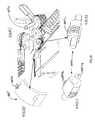
- FIGS. 56-59illustrate aspects of an intermediate region of the suturing device illustrated in FIGS. 1-3 .
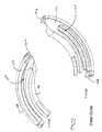
- needle 300can then be advanced through track by advancing pawl 160 to a distal extremity along its path of reciprocation.
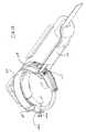
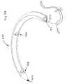
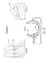
- FIG. 7illustrates needle 300 spanning the gap 110 , wherein needle 300 , being about 180° in arcuate extent, is essentially located outside of the enclosure defined by housing segments 106 , 108 , 112 .
- Wires 172 - 178can take any suitable form, most preferably multi-strand 300 series Stainless Steel cables 0.009′′ in diameter. These ends are then crimped, adhered or otherwise attached to the crimps. Then by applying tension to one wire in each pair attached to each guide, the guides 120 , 130 are pulled into or out of the suture head 100 .
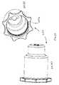
- FIGS. 33-37illustrate an embodiment of a needle loader 180 that is configured for loading a suturing needle ( 300 , 350 , 400 ) into suture head 100 .
- Needle loader 180has two main components, including a main body portion 182 and an advancement portion 184 .
- Pin 184 a of advancement portionis received in opening 182 a of main body portion 182 .
- Main body portion 182defines a groove 182 f for receiving a suturing needle ( 300 , 350 , 400 ).
- Main body portion 182includes a central portion 182 d and clip portions 182 c , 182 e that fit over suture head 100 . If desired, clip portions 182 c , 182 e may be adapted to snap fit over suture head 100 .
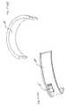
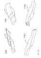
- FIGS. 38-40illustrate a first embodiment of a suturing needle 300 .
- Needle 300includes an arcuate body defined by a leading end 302 , a trailing end 304 and a generally toroidal surface 305 .
- Needle 300includes a plurality of notches 306 , 308 , 310 formed therein, as well as an opening 312 in trailing end 304 for receiving an end of a length of suturing material 312 a .
- Notches 306 , 308are located on an inner radial region 322 of needle, while notch 310 has a projection that lies within a plane P′ that is defined by the central curved axis X′ of the needle.
- drive member 150should ideally be metallic.
- member 150is made from hardened stainless steel that has been heat treated to HR 900 , and may have a chromium coating, such as an Armoloy ME 92® coating commercially available from ME-92® West/Armoloy® of Illinois, 118 Simonds Avenue, DeKalb, Ill. 60115, (815) 758-6691.
- member 150is 17-7 PH Stainless steel, condition “C” that is then hardened to condition CH900, and then coated with a ME 92® coating.
- the ME-92® coatingis applied after 900 Heat Treatment.
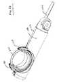
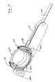
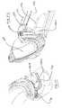
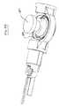
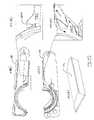
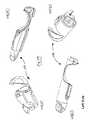
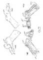
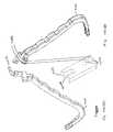
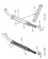
- FIGS. 56-59illustrate aspects of the intermediate region 500 of device 1000 .
- Intermediate region 500includes an elongate, preferably metallic tube 510 having a proximal end and a distal end 514 .
- Distal end 514 of tube 510is attached to a knuckle assembly 520 , which in turn is pivotally attached at pivot 114 to suture head 110 .
- a pulley 515is located at pivot 114 to serve as a bearing surface for adjoined articulation cables 532 , 534 and cables 532 , 534 are preferably affixed to pulley 515 to provide leverage for accomplishing articulation.
- stop surface 614 sis defined in left housing 614 to define a stop point for trigger 700 when trigger 700 is locked.
- Right housing 612includes a similar stop feature 612 s ( FIG. 79(D) ).
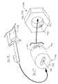
- Articulation knob 810( FIG. 77(E) ) includes a handle portion 812 , an elongate shaft 814 for engaging with brake rotate fitting 830 ( FIG. 83 ), and a distal portion 816 that is preferably threaded for receiving a hex nut 886 ( FIG. 90 ).
- Right and left handle cap portions 616 , 618FIGS.
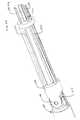
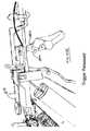
- FIGS. 103-113illustrate aspects of the operation of reciprocating trigger mechanism 700 .
- FIG. 103illustrates the relative positions of trigger 700 , pull cable/ribbon 710 , trigger spring capsule 720 , trigger return spring 730 , pull cable 727 and pulley 750 .
- FIG. 103removes components 786 , 787 and handle 700 to reveal ferrule 752 , which is fixed to a terminal end of pull cable 727 and resides within an opening 701 within handle 700 ( FIG. 105 ).
- Trigger 700is further illustrated in FIGS. 106(A)-106(B) from two additional angles, showing bifurcated yoke 702 proximate the top end of trigger 700 .
- FIG. 109illustrates the assembly with spring 730 and housing portion 720 b removed.
- FIG. 110illustrates a closeup of the connection of drive member 710 to assembly 720 , showing the manner in which tabs 711 , 712 at proximal end of drive member 710 are bent and inserted through the slot 721 a in washer plate 721 .
- O-rings 720which may be silicone or other suitable material, are illustrated in FIGS. 104 and 109 .
- O-rings 729provide a seal against housing segments 612 , 614 .
- Ferrule 723is secured to cable 727 .
- FIGS. 111-113provide closer views of ferrule 723 , washer plate 721 and proximal end of member 710 , respectively.
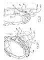
- FIG. 124illustrates the initial deployment of guides.
- Pawl 115 ais dragged along surface 322 of needle 300 until it engages with notch 308 and pawl 115 b engages with notch 306 .
- Guidesare then fully retracted in FIG. 125 , and pawl 115 a situated in guide 120 drags needle 300 in a clockwise direction to present it for suturing.
- Pawl 160meanwhile is advanced along its arcuate track along guides 120 , 130 to its distalmost extent, causing notch 158 in the drive member 150 to align with boss 108 a , and pawl 115 b bears against surface 122 of needle 300 .
Landscapes
- Health & Medical Sciences (AREA)
- Life Sciences & Earth Sciences (AREA)
- Surgery (AREA)
- Heart & Thoracic Surgery (AREA)
- Engineering & Computer Science (AREA)
- Biomedical Technology (AREA)
- Nuclear Medicine, Radiotherapy & Molecular Imaging (AREA)
- Medical Informatics (AREA)
- Molecular Biology (AREA)
- Animal Behavior & Ethology (AREA)
- General Health & Medical Sciences (AREA)
- Public Health (AREA)
- Veterinary Medicine (AREA)
- Surgical Instruments (AREA)
Abstract
Description
Claims (17)
Priority Applications (22)
| Application Number | Priority Date | Filing Date | Title |
|---|---|---|---|
| US12/909,606US7993354B1 (en) | 2010-10-01 | 2010-10-21 | Devices and methods for minimally invasive suturing |
| US13/204,820US9775600B2 (en) | 2010-10-01 | 2011-08-08 | Devices and methods for minimally invasive suturing |
| JP2013531932AJP5873501B2 (en) | 2010-10-01 | 2011-09-30 | Apparatus and method for minimally invasive suturing |
| CA2977643ACA2977643A1 (en) | 2010-10-01 | 2011-09-30 | Arcuate suturing needle |
| CN2011800562732ACN103220990A (en) | 2010-10-01 | 2011-09-30 | Devices and methods for minimally invasive suturing |
| AU2011308586AAU2011308586A1 (en) | 2010-10-01 | 2011-09-30 | Devices and methods for minimally invasive suturing |
| KR1020137011272AKR101531659B1 (en) | 2010-10-01 | 2011-09-30 | Devices for minimally invasive suturing |
| CA2812960ACA2812960C (en) | 2010-10-01 | 2011-09-30 | Arcuate suturing needle |
| CA2977640ACA2977640A1 (en) | 2010-10-01 | 2011-09-30 | Acurate suturing needle |
| PCT/US2011/054334WO2012044998A2 (en) | 2010-10-01 | 2011-09-30 | Devices and methods for minimally invasive suturing |
| EP19208832.6AEP3628240B1 (en) | 2010-10-01 | 2011-09-30 | Devices for minimally invasive suturing |
| EP11830008.6AEP2621349B1 (en) | 2010-10-01 | 2011-09-30 | Devices for minimally invasive suturing |
| AU2015238788AAU2015238788C1 (en) | 2010-10-01 | 2015-10-06 | Devices and methods for minimally invasive suturing |
| US15/377,562US9675339B2 (en) | 2004-09-20 | 2016-12-13 | Devices and methods for minimally invasive suturing |
| US15/610,277US9962151B2 (en) | 2010-10-01 | 2017-05-31 | Devices and methods for minimally invasive suturing |
| AU2017206251AAU2017206251B2 (en) | 2010-10-01 | 2017-07-20 | Devices and methods for minimally invasive suturing |
| US15/942,509US10792031B2 (en) | 2010-10-01 | 2018-03-31 | Devices and methods for minimally invasive suturing |
| AU2018202790AAU2018202790B2 (en) | 2010-10-01 | 2018-04-21 | Devices and methods for minimally invasive suturing |
| US16/236,966US10881392B2 (en) | 2010-10-01 | 2018-12-31 | Devices and methods for minimally invasive suturing |
| AU2019202851AAU2019202851B2 (en) | 2010-10-01 | 2019-04-23 | Devices and methods for minimally invasive suturing |
| US17/100,922US11986179B2 (en) | 2010-10-01 | 2020-11-22 | Devices and methods for minimally invasive suturing |
| US18/490,860US20240050086A1 (en) | 2010-10-01 | 2023-10-20 | Devices and methods for minimally invasive suturing |
Applications Claiming Priority (2)
| Application Number | Priority Date | Filing Date | Title |
|---|---|---|---|
| US38864810P | 2010-10-01 | 2010-10-01 | |
| US12/909,606US7993354B1 (en) | 2010-10-01 | 2010-10-21 | Devices and methods for minimally invasive suturing |
Related Child Applications (1)
| Application Number | Title | Priority Date | Filing Date |
|---|---|---|---|
| US13/204,820Continuation-In-PartUS9775600B2 (en) | 2004-09-20 | 2011-08-08 | Devices and methods for minimally invasive suturing |
Publications (1)
| Publication Number | Publication Date |
|---|---|
| US7993354B1true US7993354B1 (en) | 2011-08-09 |
Family
ID=44350727
Family Applications (1)
| Application Number | Title | Priority Date | Filing Date |
|---|---|---|---|
| US12/909,606ActiveUS7993354B1 (en) | 2004-09-20 | 2010-10-21 | Devices and methods for minimally invasive suturing |
Country Status (8)
| Country | Link |
|---|---|
| US (1) | US7993354B1 (en) |
| EP (2) | EP2621349B1 (en) |
| JP (1) | JP5873501B2 (en) |
| KR (1) | KR101531659B1 (en) |
| CN (1) | CN103220990A (en) |
| AU (5) | AU2011308586A1 (en) |
| CA (3) | CA2977643A1 (en) |
| WO (1) | WO2012044998A2 (en) |
Cited By (108)
| Publication number | Priority date | Publication date | Assignee | Title |
|---|---|---|---|---|
| US20150038987A1 (en)* | 2011-12-13 | 2015-02-05 | Ethicon Endo-Surgery, Inc. | Applier For Anchoring A Lining To A Hollow Organ |
| US9125645B1 (en) | 2013-03-11 | 2015-09-08 | Ethicon Endo-Surgery, Inc. | Reciprocating needle drive without cables |
| US9173655B2 (en) | 2012-12-13 | 2015-11-03 | Ethicon Endo-Surgery, Inc. | Needle driver and pawl mechanism for circular needle applier |
| USD745146S1 (en) | 2014-06-06 | 2015-12-08 | Ethicon Endo-Surgery, Inc. | Surgical suturing device |
| DE202015008237U1 (en) | 2015-11-25 | 2016-01-18 | Jörg Neymeyer | Surgical suturing instrument for minimally invasive transendoscopic suturing |
| WO2016100348A1 (en)* | 2014-12-15 | 2016-06-23 | Lsi Solutions, Inc. | Minimally invasive surgical suturing device with improved visualization |
| US9375212B2 (en) | 2014-06-06 | 2016-06-28 | Ethicon Endo-Surgery, Llc | Circular needle applier with cleats |
| US9474522B2 (en) | 2014-06-06 | 2016-10-25 | Ethicon Endo-Surgery, Llc | Jawed receiver for needle cartridge |
| USD771811S1 (en) | 2013-03-15 | 2016-11-15 | Ethicon Endo-Surgery, Llc | Suture tray |
| WO2016196579A1 (en)* | 2015-06-01 | 2016-12-08 | Lsi Solutioins, Inc. | Needle for a minimally invasive surgical suturing device |
| WO2016196574A1 (en)* | 2015-06-01 | 2016-12-08 | Lsi Solutions, Inc. | Suturing device for minimally invasive surgery and needles and methods thereof |
| US9597071B1 (en) | 2004-09-20 | 2017-03-21 | Endoevolution, Llc | Apparatus and method for minimally invasive suturing |
| US20170119376A1 (en) | 2001-06-14 | 2017-05-04 | Endoevolution, Llc | Devices and methods for surgical suturing |
| WO2017087134A1 (en)* | 2015-11-20 | 2017-05-26 | Dura Tap Llc | Suture repair device and method |
| US9675339B2 (en) | 2004-09-20 | 2017-06-13 | Endoevolution, Llc | Devices and methods for minimally invasive suturing |
| WO2017136024A1 (en)* | 2016-02-05 | 2017-08-10 | Dura Tap Llc | Devices and methods for suture placement |
| USD800306S1 (en) | 2015-12-10 | 2017-10-17 | Ethicon Llc | Surgical suturing device |
| US9788830B2 (en) | 2014-06-06 | 2017-10-17 | Ethicon Llc | Needle cartridge with cage |
| US9820744B2 (en) | 2012-09-26 | 2017-11-21 | Children's National Medical Center | Anastomosis clipping tool with half-loop clip |
| US9883858B1 (en)* | 2015-06-15 | 2018-02-06 | Ethicon Endo-Surgery, Llc | Suturing instrument with robotic drive interface |
| WO2018075568A1 (en)* | 2016-10-17 | 2018-04-26 | Lsi Solution, Inc. | Prosthetic suturing device and methods thereof |
| US9962156B2 (en) | 2006-01-27 | 2018-05-08 | Endoevolution, Llc | Suturing needle |
| JP2018086279A (en)* | 2011-08-08 | 2018-06-07 | エンドエボリューション,エルエルシー | Suturing device |
| US10022120B2 (en) | 2015-05-26 | 2018-07-17 | Ethicon Llc | Surgical needle with recessed features |
| US10098630B2 (en) | 2004-09-20 | 2018-10-16 | Endoevolution, Llc | Apparatus and method for minimally invasive suturing |
| US10149678B1 (en)* | 2015-06-17 | 2018-12-11 | Ethicon Llc | Suturing instrument with elastomeric cleat |
| US20190021723A1 (en)* | 2017-07-20 | 2019-01-24 | Dura Tap Llc | Devices and methods for suture placement |
| US20190125336A1 (en)* | 2017-10-30 | 2019-05-02 | Ethicon Llc | Surgical suturing instrument comprising a non-circular needle |
| US10292698B2 (en) | 2017-07-27 | 2019-05-21 | Endoevolution, Llc | Apparatus and method for minimally invasive suturing |
| USD865964S1 (en) | 2017-01-05 | 2019-11-05 | Ethicon Llc | Handle for electrosurgical instrument |
| US10542968B2 (en) | 2016-12-23 | 2020-01-28 | Brigham And Women's Hospital, Inc. | Systems and methods for suturing tissue |
| US10603031B2 (en) | 2017-02-03 | 2020-03-31 | Lsi Solutions, Inc. | Suturing device for minimally invasive surgery |
| US10709443B2 (en) | 2018-03-01 | 2020-07-14 | Durastat Llc | Devices and methods for suture placement |
| USD895112S1 (en) | 2018-11-15 | 2020-09-01 | Ethicon Llc | Laparoscopic bipolar electrosurgical device |
| US10799233B2 (en) | 2012-05-01 | 2020-10-13 | Brigham And Women's Hospital, Inc. | Suturing device for laparoscopic procedures |
| US20220000473A1 (en)* | 2018-12-03 | 2022-01-06 | Mayo Foundation For Medical Education And Research | Method and device for vesicourethral anastomosis |
| US11253250B2 (en) | 2017-02-26 | 2022-02-22 | Intuitive Surgical Operations, Inc. | Apparatus and method for minimally invasive suturing |
| US11337688B2 (en) | 2015-06-01 | 2022-05-24 | Lsi Solutions, Inc. | Suturing device for minimally invasive surgery and needles and methods thereof |
| WO2022254423A1 (en)* | 2021-06-04 | 2022-12-08 | Rambam Medtech Ltd. | Needle guide tools |
| WO2022256704A1 (en)* | 2021-06-03 | 2022-12-08 | EnVision Endoscopy, Inc. | Endoscopic suturing device with needle loader |
| US11589865B2 (en) | 2018-03-28 | 2023-02-28 | Cilag Gmbh International | Methods for controlling a powered surgical stapler that has separate rotary closure and firing systems |
| US11589915B2 (en) | 2018-03-08 | 2023-02-28 | Cilag Gmbh International | In-the-jaw classifier based on a model |
| US11589932B2 (en) | 2017-12-28 | 2023-02-28 | Cilag Gmbh International | Usage and technique analysis of surgeon / staff performance against a baseline to optimize device utilization and performance for both current and future procedures |
| US11596291B2 (en) | 2017-12-28 | 2023-03-07 | Cilag Gmbh International | Method of compressing tissue within a stapling device and simultaneously displaying of the location of the tissue within the jaws |
| US11601371B2 (en) | 2017-12-28 | 2023-03-07 | Cilag Gmbh International | Surgical network determination of prioritization of communication, interaction, or processing based on system or device needs |
| US11612444B2 (en) | 2017-12-28 | 2023-03-28 | Cilag Gmbh International | Adjustment of a surgical device function based on situational awareness |
| US11653912B2 (en) | 2019-12-12 | 2023-05-23 | Intuitive Surgical Operations, Inc. | Needle driver devices and related systems and methods |
| US11659023B2 (en) | 2017-12-28 | 2023-05-23 | Cilag Gmbh International | Method of hub communication |
| US11666331B2 (en) | 2017-12-28 | 2023-06-06 | Cilag Gmbh International | Systems for detecting proximity of surgical end effector to cancerous tissue |
| US11672605B2 (en) | 2017-12-28 | 2023-06-13 | Cilag Gmbh International | Sterile field interactive control displays |
| US11678881B2 (en) | 2017-12-28 | 2023-06-20 | Cilag Gmbh International | Spatial awareness of surgical hubs in operating rooms |
| US11696760B2 (en) | 2017-12-28 | 2023-07-11 | Cilag Gmbh International | Safety systems for smart powered surgical stapling |
| US11701139B2 (en) | 2018-03-08 | 2023-07-18 | Cilag Gmbh International | Methods for controlling temperature in ultrasonic device |
| US11701185B2 (en) | 2017-12-28 | 2023-07-18 | Cilag Gmbh International | Wireless pairing of a surgical device with another device within a sterile surgical field based on the usage and situational awareness of devices |
| US11707293B2 (en) | 2018-03-08 | 2023-07-25 | Cilag Gmbh International | Ultrasonic sealing algorithm with temperature control |
| US11737668B2 (en) | 2017-12-28 | 2023-08-29 | Cilag Gmbh International | Communication hub and storage device for storing parameters and status of a surgical device to be shared with cloud based analytics systems |
| US11744604B2 (en) | 2017-12-28 | 2023-09-05 | Cilag Gmbh International | Surgical instrument with a hardware-only control circuit |
| US11751872B2 (en) | 2019-02-19 | 2023-09-12 | Cilag Gmbh International | Insertable deactivator element for surgical stapler lockouts |
| US11751958B2 (en) | 2017-12-28 | 2023-09-12 | Cilag Gmbh International | Surgical hub coordination of control and communication of operating room devices |
| US11775682B2 (en) | 2017-12-28 | 2023-10-03 | Cilag Gmbh International | Data stripping method to interrogate patient records and create anonymized record |
| US11771487B2 (en) | 2017-12-28 | 2023-10-03 | Cilag Gmbh International | Mechanisms for controlling different electromechanical systems of an electrosurgical instrument |
| US11779337B2 (en) | 2017-12-28 | 2023-10-10 | Cilag Gmbh International | Method of using reinforced flexible circuits with multiple sensors to optimize performance of radio frequency devices |
| US11786245B2 (en) | 2017-12-28 | 2023-10-17 | Cilag Gmbh International | Surgical systems with prioritized data transmission capabilities |
| US11786251B2 (en) | 2017-12-28 | 2023-10-17 | Cilag Gmbh International | Method for adaptive control schemes for surgical network control and interaction |
| US11801098B2 (en) | 2017-10-30 | 2023-10-31 | Cilag Gmbh International | Method of hub communication with surgical instrument systems |
| US11818052B2 (en) | 2017-12-28 | 2023-11-14 | Cilag Gmbh International | Surgical network determination of prioritization of communication, interaction, or processing based on system or device needs |
| US11832899B2 (en) | 2017-12-28 | 2023-12-05 | Cilag Gmbh International | Surgical systems with autonomously adjustable control programs |
| US11857152B2 (en) | 2017-12-28 | 2024-01-02 | Cilag Gmbh International | Surgical hub spatial awareness to determine devices in operating theater |
| US11864728B2 (en) | 2017-12-28 | 2024-01-09 | Cilag Gmbh International | Characterization of tissue irregularities through the use of mono-chromatic light refractivity |
| US11871969B2 (en) | 2021-03-03 | 2024-01-16 | Acustitch, Llc | System and method for osseous reconstruction and repair and implant device |
| US11871901B2 (en) | 2012-05-20 | 2024-01-16 | Cilag Gmbh International | Method for situational awareness for surgical network or surgical network connected device capable of adjusting function based on a sensed situation or usage |
| US11890065B2 (en) | 2017-12-28 | 2024-02-06 | Cilag Gmbh International | Surgical system to limit displacement |
| US11896443B2 (en) | 2017-12-28 | 2024-02-13 | Cilag Gmbh International | Control of a surgical system through a surgical barrier |
| US11896322B2 (en) | 2017-12-28 | 2024-02-13 | Cilag Gmbh International | Sensing the patient position and contact utilizing the mono-polar return pad electrode to provide situational awareness to the hub |
| US11903587B2 (en) | 2017-12-28 | 2024-02-20 | Cilag Gmbh International | Adjustment to the surgical stapling control based on situational awareness |
| US11903601B2 (en) | 2017-12-28 | 2024-02-20 | Cilag Gmbh International | Surgical instrument comprising a plurality of drive systems |
| US11911045B2 (en) | 2017-10-30 | 2024-02-27 | Cllag GmbH International | Method for operating a powered articulating multi-clip applier |
| US11918204B2 (en) | 2015-06-01 | 2024-03-05 | Lsi Solutions, Inc. | Suturing device for minimally invasive surgery and needles and methods thereof |
| US11925350B2 (en) | 2019-02-19 | 2024-03-12 | Cilag Gmbh International | Method for providing an authentication lockout in a surgical stapler with a replaceable cartridge |
| US11931027B2 (en) | 2018-03-28 | 2024-03-19 | Cilag Gmbh Interntional | Surgical instrument comprising an adaptive control system |
| US11937769B2 (en) | 2017-12-28 | 2024-03-26 | Cilag Gmbh International | Method of hub communication, processing, storage and display |
| US11969216B2 (en) | 2017-12-28 | 2024-04-30 | Cilag Gmbh International | Surgical network recommendations from real time analysis of procedure variables against a baseline highlighting differences from the optimal solution |
| US11998193B2 (en) | 2017-12-28 | 2024-06-04 | Cilag Gmbh International | Method for usage of the shroud as an aspect of sensing or controlling a powered surgical device, and a control algorithm to adjust its default operation |
| US12009095B2 (en) | 2017-12-28 | 2024-06-11 | Cilag Gmbh International | Real-time analysis of comprehensive cost of all instrumentation used in surgery utilizing data fluidity to track instruments through stocking and in-house processes |
| US12029506B2 (en) | 2017-12-28 | 2024-07-09 | Cilag Gmbh International | Method of cloud based data analytics for use with the hub |
| US12035983B2 (en) | 2017-10-30 | 2024-07-16 | Cilag Gmbh International | Method for producing a surgical instrument comprising a smart electrical system |
| US12035890B2 (en) | 2017-12-28 | 2024-07-16 | Cilag Gmbh International | Method of sensing particulate from smoke evacuated from a patient, adjusting the pump speed based on the sensed information, and communicating the functional parameters of the system to the hub |
| US12042207B2 (en) | 2017-12-28 | 2024-07-23 | Cilag Gmbh International | Estimating state of ultrasonic end effector and control system therefor |
| US12048496B2 (en) | 2017-12-28 | 2024-07-30 | Cilag Gmbh International | Adaptive control program updates for surgical hubs |
| US12059218B2 (en) | 2017-10-30 | 2024-08-13 | Cilag Gmbh International | Method of hub communication with surgical instrument systems |
| US12059169B2 (en) | 2017-12-28 | 2024-08-13 | Cilag Gmbh International | Controlling an ultrasonic surgical instrument according to tissue location |
| US12062442B2 (en) | 2017-12-28 | 2024-08-13 | Cilag Gmbh International | Method for operating surgical instrument systems |
| US12076010B2 (en) | 2017-12-28 | 2024-09-03 | Cilag Gmbh International | Surgical instrument cartridge sensor assemblies |
| US12127729B2 (en) | 2017-12-28 | 2024-10-29 | Cilag Gmbh International | Method for smoke evacuation for surgical hub |
| US12133773B2 (en) | 2017-12-28 | 2024-11-05 | Cilag Gmbh International | Surgical hub and modular device response adjustment based on situational awareness |
| US12137991B2 (en) | 2017-12-28 | 2024-11-12 | Cilag Gmbh International | Display arrangements for robot-assisted surgical platforms |
| US12144518B2 (en) | 2017-12-28 | 2024-11-19 | Cilag Gmbh International | Surgical systems for detecting end effector tissue distribution irregularities |
| US12193766B2 (en) | 2017-12-28 | 2025-01-14 | Cilag Gmbh International | Situationally aware surgical system configured for use during a surgical procedure |
| US12226166B2 (en) | 2017-12-28 | 2025-02-18 | Cilag Gmbh International | Surgical instrument with a sensing array |
| US12226151B2 (en) | 2017-12-28 | 2025-02-18 | Cilag Gmbh International | Capacitive coupled return path pad with separable array elements |
| US12310586B2 (en) | 2017-12-28 | 2025-05-27 | Cilag Gmbh International | Method for adaptive control schemes for surgical network control and interaction |
| US12318152B2 (en) | 2017-12-28 | 2025-06-03 | Cilag Gmbh International | Computer implemented interactive surgical systems |
| US12329467B2 (en) | 2017-10-30 | 2025-06-17 | Cilag Gmbh International | Method of hub communication with surgical instrument systems |
| US12376855B2 (en) | 2017-12-28 | 2025-08-05 | Cilag Gmbh International | Safety systems for smart powered surgical stapling |
| US12383115B2 (en) | 2017-12-28 | 2025-08-12 | Cilag Gmbh International | Method for smart energy device infrastructure |
| US12396806B2 (en) | 2017-12-28 | 2025-08-26 | Cilag Gmbh International | Adjustment of a surgical device function based on situational awareness |
| US12402877B2 (en) | 2021-06-07 | 2025-09-02 | Intuitive Surgical Operations, Inc. | Needle loader devices and related systems and methods |
| US12433508B2 (en) | 2017-12-28 | 2025-10-07 | Cilag Gmbh International | Surgical system having a surgical instrument controlled based on comparison of sensor and database data |
Families Citing this family (2)
| Publication number | Priority date | Publication date | Assignee | Title |
|---|---|---|---|---|
| US11298122B2 (en) | 2018-06-07 | 2022-04-12 | EnVision Endoscopy, Inc. | Endoscopic suturing device with circular needle |
| JP2023532246A (en)* | 2020-06-22 | 2023-07-27 | エンビジョン・エンドスコピー,インコーポレーテッド | Endoscopic suturing device |
Citations (90)
| Publication number | Priority date | Publication date | Assignee | Title |
|---|---|---|---|---|
| US1822330A (en) | 1930-01-13 | 1931-09-08 | Ainslie George | Suturing instrument |
| US2601564A (en) | 1950-07-08 | 1952-06-24 | David P Smith | Suturing device |
| US3311110A (en) | 1964-07-15 | 1967-03-28 | American Cyanamid Co | Flexible composite suture having a tandem linkage |
| US3762418A (en) | 1972-05-17 | 1973-10-02 | W Wasson | Surgical suture |
| US3835912A (en) | 1973-06-25 | 1974-09-17 | S K S Ltd | Method of joining a filament to a metal rod |
| US4437465A (en) | 1979-05-17 | 1984-03-20 | Janome Sewing Machine Co., Ltd. | Medical treatment sewing machine |
| FR2540377A1 (en) | 1983-02-08 | 1984-08-10 | Innova Ab | SUTURING APPARATUS |
| US4621640A (en) | 1984-01-09 | 1986-11-11 | Mulhollan James S | Mechanical needle carrier and method for its use |
| US4899746A (en) | 1988-04-28 | 1990-02-13 | Brunk Industries, Inc. | Suturing apparatus |
| US5080663A (en) | 1990-09-26 | 1992-01-14 | Univerity College London | Sewing device |
| US5089012A (en) | 1989-02-20 | 1992-02-18 | Ethicon, Inc. | Surgical suture, in particular for sternotomy closure |
| US5305281A (en) | 1992-08-06 | 1994-04-19 | National Semiconductor Corporation | Multiple array memory device with staggered read/write for high speed data access |
| US5306281A (en) | 1992-08-31 | 1994-04-26 | Merrimac Industries, Inc. | Suturing cassette device |
| US5308353A (en) | 1992-08-31 | 1994-05-03 | Merrimac Industries, Inc. | Surgical suturing device |
| US5364408A (en)* | 1992-09-04 | 1994-11-15 | Laurus Medical Corporation | Endoscopic suture system |
| US5373101A (en) | 1991-05-03 | 1994-12-13 | Motorola, Inc. | Electrical interconnect apparatus |
| US5387221A (en) | 1991-01-17 | 1995-02-07 | Bisgaard; Therkel | Set of tools for suturing in deep surgical apertures or body cavities |
| US5437681A (en) | 1994-01-13 | 1995-08-01 | Suturtek Inc. | Suturing instrument with thread management |
| US5462558A (en) | 1994-08-29 | 1995-10-31 | United States Surgical Corporation | Suture clip applier |
| US5474568A (en) | 1993-10-08 | 1995-12-12 | United States Surgical Corporation | Instrument for closing trocar puncture wounds |
| US5514159A (en) | 1994-09-13 | 1996-05-07 | United States Surgical Corporation | Guillotine suture clip |
| US5540705A (en) | 1995-05-19 | 1996-07-30 | Suturtek, Inc. | Suturing instrument with thread management |
| US5571119A (en) | 1993-10-25 | 1996-11-05 | Children's Medical Center Corporation | Retractable suture needle with self-contained driver |
| US5578044A (en) | 1992-09-04 | 1996-11-26 | Laurus Medical Corporation | Endoscopic suture system |
| US5643295A (en) | 1994-12-29 | 1997-07-01 | Yoon; Inbae | Methods and apparatus for suturing tissue |
| US5665109A (en) | 1994-12-29 | 1997-09-09 | Yoon; Inbae | Methods and apparatus for suturing tissue |
| US5665096A (en) | 1995-03-07 | 1997-09-09 | Yoon; Inbae | Needle driving apparatus and methods of suturing tissue |
| US5709693A (en) | 1996-02-20 | 1998-01-20 | Cardiothoracic System, Inc. | Stitcher |
| US5713910A (en) | 1992-09-04 | 1998-02-03 | Laurus Medical Corporation | Needle guidance system for endoscopic suture device |
| US5741277A (en) | 1992-09-04 | 1998-04-21 | Laurus Medical Corporation | Endoscopic suture system |
| US5759188A (en) | 1996-11-27 | 1998-06-02 | Yoon; Inbae | Suturing instrument with rotatably mounted needle driver and catcher |
| US5766186A (en) | 1996-12-03 | 1998-06-16 | Simon Fraser University | Suturing device |
| US5814071A (en) | 1994-11-10 | 1998-09-29 | Innovasive Devices, Inc. | Suture anchor assembly and methods |
| US5860992A (en) | 1996-01-31 | 1999-01-19 | Heartport, Inc. | Endoscopic suturing devices and methods |
| US5908428A (en) | 1997-05-27 | 1999-06-01 | United States Surgical Corporation | Stitching devices for heart valve replacement surgery |
| US5908426A (en) | 1997-04-24 | 1999-06-01 | Pierce; Javin | Suture needle manipulator |
| US5911727A (en) | 1996-02-20 | 1999-06-15 | Cardiothoracic Systems, Inc. | Stitcher |
| US6036694A (en) | 1998-08-03 | 2000-03-14 | Innovasive Devices, Inc. | Self-tensioning soft tissue fixation device and method |
| US6048351A (en) | 1992-09-04 | 2000-04-11 | Scimed Life Systems, Inc. | Transvaginal suturing system |
| US6071289A (en) | 1999-03-15 | 2000-06-06 | Ethicon Endo-Surgery, Inc. | Surgical device for suturing tissue |
| US6136010A (en) | 1999-03-04 | 2000-10-24 | Perclose, Inc. | Articulating suturing device and method |
| US6159224A (en) | 1996-11-27 | 2000-12-12 | Yoon; Inbae | Multiple needle suturing instrument and method |
| US20020107530A1 (en) | 2001-02-02 | 2002-08-08 | Sauer Jude S. | System for endoscopic suturing |
| US6443962B1 (en) | 1997-09-11 | 2002-09-03 | Benny Gaber | Stitching tool |
| US6454778B2 (en) | 1998-03-20 | 2002-09-24 | Scimed Life Systems, Inc. | Endoscopic suture systems |
| US6494888B1 (en) | 1999-06-22 | 2002-12-17 | Ndo Surgical, Inc. | Tissue reconfiguration |
| US6506196B1 (en) | 1999-06-22 | 2003-01-14 | Ndo Surgical, Inc. | Device and method for correction of a painful body defect |
| US20030083674A1 (en) | 2001-10-04 | 2003-05-01 | Gibbens George H. | Cycling suturing and knot-tying device |
| US6558400B2 (en) | 2001-05-30 | 2003-05-06 | Satiety, Inc. | Obesity treatment tools and methods |
| US20030171760A1 (en) | 2000-05-19 | 2003-09-11 | Gambale Richard A | Tissue capturing and suturing device and method |
| US20030181924A1 (en) | 2002-01-30 | 2003-09-25 | Olympus Optical Co., Ltd. | Endoscopic suturing system |
| US6656194B1 (en) | 2002-11-05 | 2003-12-02 | Satiety, Inc. | Magnetic anchoring devices |
| US6663639B1 (en) | 1999-06-22 | 2003-12-16 | Ndo Surgical, Inc. | Methods and devices for tissue reconfiguration |
| US20030233104A1 (en) | 2002-06-12 | 2003-12-18 | Scimed Life Systems, Inc. | Suturing instrument with deflectable head |
| WO2004012606A1 (en) | 2002-08-02 | 2004-02-12 | Scimed Life Systems, Inc. | Placing sutures |
| US20040034369A1 (en) | 2001-02-02 | 2004-02-19 | Sauer Jude S. | System for endoscopic suturing |
| US20040044354A1 (en) | 2002-08-30 | 2004-03-04 | Satiety, Inc. | Methods and devices for maintaining a space occupying device in a relatively fixed location within a stomach |
| WO2004021894A1 (en) | 2002-09-09 | 2004-03-18 | Brian Kelleher | Device and method for endoluminal therapy |
| US20040059350A1 (en) | 1992-09-04 | 2004-03-25 | Scimed Life Systems, Inc. | Suturing instruments and methods of use |
| US6719763B2 (en) | 2000-09-29 | 2004-04-13 | Olympus Optical Co., Ltd. | Endoscopic suturing device |
| US6719764B1 (en) | 2001-08-24 | 2004-04-13 | Scimed Life Systems, Inc. | Forward deploying suturing device and methods of use |
| US20040082963A1 (en) | 2002-10-23 | 2004-04-29 | Jamy Gannoe | Method and device for use in endoscopic organ procedures |
| US6746460B2 (en) | 2002-08-07 | 2004-06-08 | Satiety, Inc. | Intra-gastric fastening devices |
| US20040122473A1 (en) | 2002-12-11 | 2004-06-24 | Ewers Richard C. | Delivery systems and methods for gastric reduction |
| US6755843B2 (en) | 2000-09-29 | 2004-06-29 | Olympus Optical Co., Ltd. | Endoscopic suturing device |
| US20040138682A1 (en) | 2002-07-11 | 2004-07-15 | Olympus Optical Co., Ltd. | Endoscopic suture apparatus |
| US20040147958A1 (en) | 2002-12-11 | 2004-07-29 | Usgi Medical | Apparatus and methods for forming and securing gastrointestinal tissue folds |
| US20040147941A1 (en) | 2002-01-30 | 2004-07-29 | Olympus Corporation | Endoscopic suturing system |
| US20040162568A1 (en) | 1999-06-25 | 2004-08-19 | Usgi Medical | Apparatus and methods for forming and securing gastrointestinal tissue folds |
| US20040194790A1 (en) | 1999-06-22 | 2004-10-07 | Ndo Surgical, Inc. | Tissue reconfiguration |
| US20040210243A1 (en) | 2003-04-16 | 2004-10-21 | Jamy Gannoe | Method and devices for modifying the function of a body organ |
| US20040260344A1 (en) | 2003-05-07 | 2004-12-23 | Anpa Medical, Inc. | Suture lock |
| US6835200B2 (en) | 1999-06-22 | 2004-12-28 | Ndo Surgical. Inc. | Method and devices for tissue reconfiguration |
| US20050015101A1 (en) | 2001-10-04 | 2005-01-20 | Gibbens George H. | Leverage locking reversible cyclic suturing and knot-tying device |
| US20050070931A1 (en) | 2003-08-06 | 2005-03-31 | Rhodemann Li | Method and apparatus for creating a restriction in the stomach or other anatomical structure |
| US6908427B2 (en) | 2002-12-30 | 2005-06-21 | PARÉ Surgical, Inc. | Flexible endoscope capsule |
| US6923819B2 (en) | 2001-06-14 | 2005-08-02 | Suturtek Incorporated | Apparatus and method for surgical suturing with thread management |
| US20060069396A1 (en)* | 2004-09-20 | 2006-03-30 | Suturtek Incorporated | Apparatus and method for minimally invasive suturing |
| US20060111732A1 (en)* | 2002-10-03 | 2006-05-25 | George Gibbens | Cycling suturing and knot-tying device |
| US7144401B2 (en) | 2001-06-07 | 2006-12-05 | Olympus Optical Co., Ltd. | Suturing device for endoscope |
| US20060282092A1 (en) | 2005-06-13 | 2006-12-14 | Stokes Michael J | Surgical suturing apparatus with needle position indicator |
| US20060282099A1 (en) | 2005-06-13 | 2006-12-14 | Stokes Michael J | Method for suture lacing |
| US20060282089A1 (en) | 2005-06-13 | 2006-12-14 | Ethicon Endo-Surgery, Inc. | Endoscopic suturing device |
| US20060282093A1 (en) | 2005-06-13 | 2006-12-14 | Shelton Frederick E Iv | Surgical suturing apparatus with anti-backup system |
| US20060282091A1 (en) | 2005-06-13 | 2006-12-14 | Shelton Frederick E Iv | Adjustable vacuum chamber for a surgical suturing apparatus |
| US20060282094A1 (en) | 2005-06-13 | 2006-12-14 | Stokes Michael J | Surgical suturing apparatus |
| WO2007089603A2 (en) | 2006-01-27 | 2007-08-09 | Suturtek Incorporated | Apparatus and method for tissue closure |
| US20080140091A1 (en)* | 2006-12-12 | 2008-06-12 | Dedeyne Patrick G | Minimally invasive suture-based repair of soft tissue |
| WO2008147555A2 (en) | 2007-05-24 | 2008-12-04 | Suturtek Incorporated | Apparatus and method for minimally invasive suturing |
| WO2010062380A2 (en) | 2008-11-25 | 2010-06-03 | Endoevolution, Llc | Apparatus and method for minimally invasive suturing |
Family Cites Families (11)
| Publication number | Priority date | Publication date | Assignee | Title |
|---|---|---|---|---|
| US5403344A (en)* | 1993-07-22 | 1995-04-04 | American Cyanamid Co. | Multi-faceted surgical needle |
| US5478327A (en)* | 1993-10-18 | 1995-12-26 | Ethicon, Inc. | Surgical needle with decreased penetration |
| JPH11276492A (en)* | 1998-03-30 | 1999-10-12 | Iken Kogyo:Kk | Surgical needle and forming device for needle material of surgical needle |
| JP2000139931A (en)* | 1998-11-17 | 2000-05-23 | Keisei Ika Kogyo Kk | Micro-suturing needle and its manufacture |
| US6997932B2 (en)* | 2001-05-21 | 2006-02-14 | Boston Scientific Scimed, Inc. | Suture passer |
| US20100042116A1 (en)* | 2002-10-03 | 2010-02-18 | Faising Chui | Cycling suturing and knot-tying device |
| WO2005077279A1 (en) | 2004-02-09 | 2005-08-25 | Eclectic Grey Mater Designs, Llc | Safety suture needle assemblies and methods |
| ZA200610827B (en)* | 2004-05-21 | 2008-07-30 | Neatstich Ltd | Suture device |
| US8123764B2 (en) | 2004-09-20 | 2012-02-28 | Endoevolution, Llc | Apparatus and method for minimally invasive suturing |
| US8211143B2 (en)* | 2005-03-31 | 2012-07-03 | David Stefanchik | Suturing device |
| WO2008084722A1 (en)* | 2007-01-11 | 2008-07-17 | Mani, Inc. | Suturing needle |
- 2010
- 2010-10-21USUS12/909,606patent/US7993354B1/enactiveActive
- 2011
- 2011-09-30EPEP11830008.6Apatent/EP2621349B1/enactiveActive
- 2011-09-30AUAU2011308586Apatent/AU2011308586A1/ennot_activeAbandoned
- 2011-09-30EPEP19208832.6Apatent/EP3628240B1/enactiveActive
- 2011-09-30CACA2977643Apatent/CA2977643A1/ennot_activeAbandoned
- 2011-09-30CNCN2011800562732Apatent/CN103220990A/enactivePending
- 2011-09-30WOPCT/US2011/054334patent/WO2012044998A2/enactiveApplication Filing
- 2011-09-30CACA2977640Apatent/CA2977640A1/ennot_activeAbandoned
- 2011-09-30KRKR1020137011272Apatent/KR101531659B1/enactiveActive
- 2011-09-30JPJP2013531932Apatent/JP5873501B2/enactiveActive
- 2011-09-30CACA2812960Apatent/CA2812960C/enactiveActive
- 2015
- 2015-10-06AUAU2015238788Apatent/AU2015238788C1/enactiveActive
- 2017
- 2017-07-20AUAU2017206251Apatent/AU2017206251B2/enactiveActive
- 2018
- 2018-04-21AUAU2018202790Apatent/AU2018202790B2/enactiveActive
- 2019
- 2019-04-23AUAU2019202851Apatent/AU2019202851B2/enactiveActive
Patent Citations (110)
| Publication number | Priority date | Publication date | Assignee | Title |
|---|---|---|---|---|
| US1822330A (en) | 1930-01-13 | 1931-09-08 | Ainslie George | Suturing instrument |
| US2601564A (en) | 1950-07-08 | 1952-06-24 | David P Smith | Suturing device |
| US3311110A (en) | 1964-07-15 | 1967-03-28 | American Cyanamid Co | Flexible composite suture having a tandem linkage |
| US3762418A (en) | 1972-05-17 | 1973-10-02 | W Wasson | Surgical suture |
| US3835912A (en) | 1973-06-25 | 1974-09-17 | S K S Ltd | Method of joining a filament to a metal rod |
| US4437465A (en) | 1979-05-17 | 1984-03-20 | Janome Sewing Machine Co., Ltd. | Medical treatment sewing machine |
| US4557265A (en) | 1983-02-08 | 1985-12-10 | Innova Ab | Suturing instrument |
| FR2540377A1 (en) | 1983-02-08 | 1984-08-10 | Innova Ab | SUTURING APPARATUS |
| US4621640A (en) | 1984-01-09 | 1986-11-11 | Mulhollan James S | Mechanical needle carrier and method for its use |
| US4899746A (en) | 1988-04-28 | 1990-02-13 | Brunk Industries, Inc. | Suturing apparatus |
| US5089012A (en) | 1989-02-20 | 1992-02-18 | Ethicon, Inc. | Surgical suture, in particular for sternotomy closure |
| US5080663A (en) | 1990-09-26 | 1992-01-14 | Univerity College London | Sewing device |
| US5387221A (en) | 1991-01-17 | 1995-02-07 | Bisgaard; Therkel | Set of tools for suturing in deep surgical apertures or body cavities |
| US5373101A (en) | 1991-05-03 | 1994-12-13 | Motorola, Inc. | Electrical interconnect apparatus |
| US5305281A (en) | 1992-08-06 | 1994-04-19 | National Semiconductor Corporation | Multiple array memory device with staggered read/write for high speed data access |
| US5306281A (en) | 1992-08-31 | 1994-04-26 | Merrimac Industries, Inc. | Suturing cassette device |
| US5308353A (en) | 1992-08-31 | 1994-05-03 | Merrimac Industries, Inc. | Surgical suturing device |
| US20040059350A1 (en) | 1992-09-04 | 2004-03-25 | Scimed Life Systems, Inc. | Suturing instruments and methods of use |
| US6048351A (en) | 1992-09-04 | 2000-04-11 | Scimed Life Systems, Inc. | Transvaginal suturing system |
| US6346111B1 (en) | 1992-09-04 | 2002-02-12 | Scimed Life Systems, Inc. | Suturing instruments and methods of use |
| US5364408A (en)* | 1992-09-04 | 1994-11-15 | Laurus Medical Corporation | Endoscopic suture system |
| US7033370B2 (en) | 1992-09-04 | 2006-04-25 | Boston Scientific Scimed, Inc. | Suturing instruments and methods of use |
| US5575800A (en) | 1992-09-04 | 1996-11-19 | Laurus Medical Corporation | Endoscopic suture system |
| US5578044A (en) | 1992-09-04 | 1996-11-26 | Laurus Medical Corporation | Endoscopic suture system |
| US5741277A (en) | 1992-09-04 | 1998-04-21 | Laurus Medical Corporation | Endoscopic suture system |
| US5713910A (en) | 1992-09-04 | 1998-02-03 | Laurus Medical Corporation | Needle guidance system for endoscopic suture device |
| US5474568A (en) | 1993-10-08 | 1995-12-12 | United States Surgical Corporation | Instrument for closing trocar puncture wounds |
| US5571119A (en) | 1993-10-25 | 1996-11-05 | Children's Medical Center Corporation | Retractable suture needle with self-contained driver |
| US5437681A (en) | 1994-01-13 | 1995-08-01 | Suturtek Inc. | Suturing instrument with thread management |
| US5462558A (en) | 1994-08-29 | 1995-10-31 | United States Surgical Corporation | Suture clip applier |
| US5514159A (en) | 1994-09-13 | 1996-05-07 | United States Surgical Corporation | Guillotine suture clip |
| US5814071A (en) | 1994-11-10 | 1998-09-29 | Innovasive Devices, Inc. | Suture anchor assembly and methods |
| US5665109A (en) | 1994-12-29 | 1997-09-09 | Yoon; Inbae | Methods and apparatus for suturing tissue |
| US5643295A (en) | 1994-12-29 | 1997-07-01 | Yoon; Inbae | Methods and apparatus for suturing tissue |
| US5665096A (en) | 1995-03-07 | 1997-09-09 | Yoon; Inbae | Needle driving apparatus and methods of suturing tissue |
| US5540705A (en) | 1995-05-19 | 1996-07-30 | Suturtek, Inc. | Suturing instrument with thread management |
| US5860992A (en) | 1996-01-31 | 1999-01-19 | Heartport, Inc. | Endoscopic suturing devices and methods |
| US5709693A (en) | 1996-02-20 | 1998-01-20 | Cardiothoracic System, Inc. | Stitcher |
| US5911727A (en) | 1996-02-20 | 1999-06-15 | Cardiothoracic Systems, Inc. | Stitcher |
| US6159224A (en) | 1996-11-27 | 2000-12-12 | Yoon; Inbae | Multiple needle suturing instrument and method |
| US5759188A (en) | 1996-11-27 | 1998-06-02 | Yoon; Inbae | Suturing instrument with rotatably mounted needle driver and catcher |
| US5766186A (en) | 1996-12-03 | 1998-06-16 | Simon Fraser University | Suturing device |
| US5908426A (en) | 1997-04-24 | 1999-06-01 | Pierce; Javin | Suture needle manipulator |
| US5908428A (en) | 1997-05-27 | 1999-06-01 | United States Surgical Corporation | Stitching devices for heart valve replacement surgery |
| US6443962B1 (en) | 1997-09-11 | 2002-09-03 | Benny Gaber | Stitching tool |
| US6454778B2 (en) | 1998-03-20 | 2002-09-24 | Scimed Life Systems, Inc. | Endoscopic suture systems |
| US6036694A (en) | 1998-08-03 | 2000-03-14 | Innovasive Devices, Inc. | Self-tensioning soft tissue fixation device and method |
| US6136010A (en) | 1999-03-04 | 2000-10-24 | Perclose, Inc. | Articulating suturing device and method |
| US6071289A (en) | 1999-03-15 | 2000-06-06 | Ethicon Endo-Surgery, Inc. | Surgical device for suturing tissue |
| US6835200B2 (en) | 1999-06-22 | 2004-12-28 | Ndo Surgical. Inc. | Method and devices for tissue reconfiguration |
| US6506196B1 (en) | 1999-06-22 | 2003-01-14 | Ndo Surgical, Inc. | Device and method for correction of a painful body defect |
| US6494888B1 (en) | 1999-06-22 | 2002-12-17 | Ndo Surgical, Inc. | Tissue reconfiguration |
| US6663639B1 (en) | 1999-06-22 | 2003-12-16 | Ndo Surgical, Inc. | Methods and devices for tissue reconfiguration |
| US20040194790A1 (en) | 1999-06-22 | 2004-10-07 | Ndo Surgical, Inc. | Tissue reconfiguration |
| US20050075653A1 (en) | 1999-06-25 | 2005-04-07 | Usgi Medical Inc. | Apparatus and methods for forming and securing gastrointestinal tissue folds |
| US20040162568A1 (en) | 1999-06-25 | 2004-08-19 | Usgi Medical | Apparatus and methods for forming and securing gastrointestinal tissue folds |
| US20030171760A1 (en) | 2000-05-19 | 2003-09-11 | Gambale Richard A | Tissue capturing and suturing device and method |
| US6719763B2 (en) | 2000-09-29 | 2004-04-13 | Olympus Optical Co., Ltd. | Endoscopic suturing device |
| US6755843B2 (en) | 2000-09-29 | 2004-06-29 | Olympus Optical Co., Ltd. | Endoscopic suturing device |
| US20020107530A1 (en) | 2001-02-02 | 2002-08-08 | Sauer Jude S. | System for endoscopic suturing |
| US20040034369A1 (en) | 2001-02-02 | 2004-02-19 | Sauer Jude S. | System for endoscopic suturing |
| US6558400B2 (en) | 2001-05-30 | 2003-05-06 | Satiety, Inc. | Obesity treatment tools and methods |
| US7144401B2 (en) | 2001-06-07 | 2006-12-05 | Olympus Optical Co., Ltd. | Suturing device for endoscope |
| EP2308391A1 (en) | 2001-06-14 | 2011-04-13 | Suturtek Incorporated | Apparatus for surgical suturing with thread management |
| US6923819B2 (en) | 2001-06-14 | 2005-08-02 | Suturtek Incorporated | Apparatus and method for surgical suturing with thread management |
| US6719764B1 (en) | 2001-08-24 | 2004-04-13 | Scimed Life Systems, Inc. | Forward deploying suturing device and methods of use |
| US20050015101A1 (en) | 2001-10-04 | 2005-01-20 | Gibbens George H. | Leverage locking reversible cyclic suturing and knot-tying device |
| US20030083674A1 (en) | 2001-10-04 | 2003-05-01 | Gibbens George H. | Cycling suturing and knot-tying device |
| US7004951B2 (en) | 2001-10-04 | 2006-02-28 | Gibbens Group Llc | Cycling suturing and knot-tying device |
| US20030181924A1 (en) | 2002-01-30 | 2003-09-25 | Olympus Optical Co., Ltd. | Endoscopic suturing system |
| US20040147941A1 (en) | 2002-01-30 | 2004-07-29 | Olympus Corporation | Endoscopic suturing system |
| US20030233104A1 (en) | 2002-06-12 | 2003-12-18 | Scimed Life Systems, Inc. | Suturing instrument with deflectable head |
| US20030233108A1 (en) | 2002-06-12 | 2003-12-18 | Scimed Life Systems, Inc. | Endoscopic suture instrument |
| US6955643B2 (en) | 2002-06-12 | 2005-10-18 | Boston Scientific Scimed, Inc. | Endoscopic suture instrument |
| US20040138682A1 (en) | 2002-07-11 | 2004-07-15 | Olympus Optical Co., Ltd. | Endoscopic suture apparatus |
| US7041111B2 (en) | 2002-08-02 | 2006-05-09 | Boston Scientific Scimed, Inc. | Placing sutures |
| WO2004012606A1 (en) | 2002-08-02 | 2004-02-12 | Scimed Life Systems, Inc. | Placing sutures |
| US20040034372A1 (en) | 2002-08-02 | 2004-02-19 | Scimed Life Systems, Inc. | Placing sutures |
| US6746460B2 (en) | 2002-08-07 | 2004-06-08 | Satiety, Inc. | Intra-gastric fastening devices |
| US20040044354A1 (en) | 2002-08-30 | 2004-03-04 | Satiety, Inc. | Methods and devices for maintaining a space occupying device in a relatively fixed location within a stomach |
| WO2004021894A1 (en) | 2002-09-09 | 2004-03-18 | Brian Kelleher | Device and method for endoluminal therapy |
| US20050055038A1 (en) | 2002-09-09 | 2005-03-10 | Brian Kelleher | Device and method for endoluminal therapy |
| US20060111732A1 (en)* | 2002-10-03 | 2006-05-25 | George Gibbens | Cycling suturing and knot-tying device |
| US20040082963A1 (en) | 2002-10-23 | 2004-04-29 | Jamy Gannoe | Method and device for use in endoscopic organ procedures |
| US20040088008A1 (en) | 2002-11-05 | 2004-05-06 | Satiety, Inc. | Magnetic anchoring devices |
| US6656194B1 (en) | 2002-11-05 | 2003-12-02 | Satiety, Inc. | Magnetic anchoring devices |
| US20040122473A1 (en) | 2002-12-11 | 2004-06-24 | Ewers Richard C. | Delivery systems and methods for gastric reduction |
| US20040147958A1 (en) | 2002-12-11 | 2004-07-29 | Usgi Medical | Apparatus and methods for forming and securing gastrointestinal tissue folds |
| US6908427B2 (en) | 2002-12-30 | 2005-06-21 | PARÉ Surgical, Inc. | Flexible endoscope capsule |
| US20040210243A1 (en) | 2003-04-16 | 2004-10-21 | Jamy Gannoe | Method and devices for modifying the function of a body organ |
| US20040260344A1 (en) | 2003-05-07 | 2004-12-23 | Anpa Medical, Inc. | Suture lock |
| US20050070931A1 (en) | 2003-08-06 | 2005-03-31 | Rhodemann Li | Method and apparatus for creating a restriction in the stomach or other anatomical structure |
| US20060069396A1 (en)* | 2004-09-20 | 2006-03-30 | Suturtek Incorporated | Apparatus and method for minimally invasive suturing |
| EP1791476A2 (en) | 2004-09-20 | 2007-06-06 | Suturtek Incorporated | Apparatus and method for minimally invasive suturing |
| US20060282093A1 (en) | 2005-06-13 | 2006-12-14 | Shelton Frederick E Iv | Surgical suturing apparatus with anti-backup system |
| US20060282097A1 (en) | 2005-06-13 | 2006-12-14 | Ortiz Mark S | Surgical suturing apparatus with a non-visible spectrum sensing member |
| US20060282091A1 (en) | 2005-06-13 | 2006-12-14 | Shelton Frederick E Iv | Adjustable vacuum chamber for a surgical suturing apparatus |
| US20060282094A1 (en) | 2005-06-13 | 2006-12-14 | Stokes Michael J | Surgical suturing apparatus |
| US20060282098A1 (en) | 2005-06-13 | 2006-12-14 | Shelton Frederick E Iv | Surgical suturing apparatus with detachable handle |
| US20060282095A1 (en) | 2005-06-13 | 2006-12-14 | Stokes Michael J | Surgical suturing apparatus with collapsible vacuum chamber |
| US20060282096A1 (en) | 2005-06-13 | 2006-12-14 | Papa Christopher A | Quick load mechanism for a surgical suturing apparatus |
| US20060282089A1 (en) | 2005-06-13 | 2006-12-14 | Ethicon Endo-Surgery, Inc. | Endoscopic suturing device |
| US20060282090A1 (en) | 2005-06-13 | 2006-12-14 | Stokes Michael J | Surgical suturing apparatus with needle release system |
| US20060282099A1 (en) | 2005-06-13 | 2006-12-14 | Stokes Michael J | Method for suture lacing |
| US20060282092A1 (en) | 2005-06-13 | 2006-12-14 | Stokes Michael J | Surgical suturing apparatus with needle position indicator |
| US7615060B2 (en)* | 2005-06-13 | 2009-11-10 | Ethicon-Endo Surgery, Inc. | Endoscopic suturing device |
| WO2007089603A2 (en) | 2006-01-27 | 2007-08-09 | Suturtek Incorporated | Apparatus and method for tissue closure |
| US20080140091A1 (en)* | 2006-12-12 | 2008-06-12 | Dedeyne Patrick G | Minimally invasive suture-based repair of soft tissue |
| WO2008147555A2 (en) | 2007-05-24 | 2008-12-04 | Suturtek Incorporated | Apparatus and method for minimally invasive suturing |
| WO2010062380A2 (en) | 2008-11-25 | 2010-06-03 | Endoevolution, Llc | Apparatus and method for minimally invasive suturing |
Non-Patent Citations (3)
| Title |
|---|
| International Preliminary Report on Patentability for PCT/US2005/033507 together with the International Search Report and the Written Opinion of the International Searching Authority (ISA) dated Jun. 13, 2008 (5 pages). |
| International Preliminary Report on Patentability for PCT/US2007/002204 together with the International Seahc Report and The Written Opinion of the International Searching Authority (ISA) dated Nov. 1, 2007 (7 pages). |
| International Search Report and the Written Opinion of The International Searching Authority (ISA) dated Jul. 5, 2010 relating to co-pending PCT/US2009/006212 (10 pages). |
Cited By (209)
| Publication number | Priority date | Publication date | Assignee | Title |
|---|---|---|---|---|
| US9743925B2 (en) | 2001-06-14 | 2017-08-29 | Endoevolution, Llc | Devices and methods for surgical suturing |
| US9730688B1 (en) | 2001-06-14 | 2017-08-15 | Endoevolution, Llc | Devices and methods for surgical suturing |
| US9717495B1 (en) | 2001-06-14 | 2017-08-01 | Endoevolution, Llc | Devices and methods for surgical suturing |
| US10792032B2 (en) | 2001-06-14 | 2020-10-06 | Intuitive Surgical Operations, Inc. | Methods of surgical fastening |
| US9693770B2 (en) | 2001-06-14 | 2017-07-04 | Endoevolution, Llc | Devices and methods for surgical suturing |
| US9737296B1 (en) | 2001-06-14 | 2017-08-22 | Endoevolution, Llc | Devices and methods for surgical suturing |
| US10045774B2 (en) | 2001-06-14 | 2018-08-14 | Endoevolution, Llc | Devices and methods for surgical fastening |
| US9743923B2 (en) | 2001-06-14 | 2017-08-29 | Endoevolution, Llc | Devices and methods for surgical suturing |
| US9717493B1 (en) | 2001-06-14 | 2017-08-01 | Endoevolution, Llc | Devices and methods for surgical suturing |
| US9649107B2 (en) | 2001-06-14 | 2017-05-16 | Endoevolution, Llc | Needle for suturing instrument |
| US9962152B2 (en) | 2001-06-14 | 2018-05-08 | Endoevolution, Llc | Devices and methods for surgical suturing |
| US9943307B2 (en) | 2001-06-14 | 2018-04-17 | Endoevolution, Llc | Devices and methods for surgical suturing |
| US9943308B2 (en) | 2001-06-14 | 2018-04-17 | Endoevolution, Llc | Devices and methods for surgical suturing |
| US9936945B2 (en) | 2001-06-14 | 2018-04-10 | Endoevolution, Llc | Devices and methods for surgical suturing |
| US20170119376A1 (en) | 2001-06-14 | 2017-05-04 | Endoevolution, Llc | Devices and methods for surgical suturing |
| US9962153B2 (en) | 2004-09-20 | 2018-05-08 | Endoevolution, Llc | Apparatus and method for minimally invasive suturing |
| US9962154B2 (en) | 2004-09-20 | 2018-05-08 | Endoevolution, Llc | Apparatus and method for minimally invasive suturing |
| US9795377B2 (en) | 2004-09-20 | 2017-10-24 | Endoevolution, Llc | Apparatus and method for minimally invasive suturing |
| US9808238B2 (en) | 2004-09-20 | 2017-11-07 | Endoevolution, Llc | Apparatus and method for minimally invasive suturing |
| US9597071B1 (en) | 2004-09-20 | 2017-03-21 | Endoevolution, Llc | Apparatus and method for minimally invasive suturing |
| US9936944B2 (en) | 2004-09-20 | 2018-04-10 | Endoevolution, Llc | Apparatus and method for minimally invasive suturing |
| US9642614B1 (en) | 2004-09-20 | 2017-05-09 | Endoevolution, Llc | Apparatus and method for minimally invasive suturing |
| US9642613B1 (en) | 2004-09-20 | 2017-05-09 | Endoevolution, Llc | Apparatus and method for minimally invasive suturing |
| US9962155B2 (en) | 2004-09-20 | 2018-05-08 | Endoevolution, Llc | Apparatus and method for minimally invasive suturing |
| US9795376B2 (en) | 2004-09-20 | 2017-10-24 | Endoevolution, Llc | Apparatus and method for minimally invasive suturing |
| US10098630B2 (en) | 2004-09-20 | 2018-10-16 | Endoevolution, Llc | Apparatus and method for minimally invasive suturing |
| US9675339B2 (en) | 2004-09-20 | 2017-06-13 | Endoevolution, Llc | Devices and methods for minimally invasive suturing |
| US10111654B2 (en) | 2004-09-20 | 2018-10-30 | Endoevolution, Llc | Apparatus and method for minimally invasive suturing |
| US9700302B2 (en) | 2004-09-20 | 2017-07-11 | Endoevolution, Llc | Suturing needles |
| US9700301B2 (en) | 2004-09-20 | 2017-07-11 | Endoevolution, Llc | Suturing needles |
| US11172922B2 (en) | 2004-09-20 | 2021-11-16 | Intuitive Surgical Operations, Inc. | Apparatus and method for minimally invasive suturing |
| US11253249B2 (en) | 2004-09-20 | 2022-02-22 | Intuitive Surgical Operations, Inc. | Apparatus and method for minimally invasive suturing |
| US9962156B2 (en) | 2006-01-27 | 2018-05-08 | Endoevolution, Llc | Suturing needle |
| US12150645B2 (en) | 2006-01-27 | 2024-11-26 | Intuitive Surgical Operations, Inc. | Systems and methods for tissue closure |
| US10307155B2 (en) | 2006-01-27 | 2019-06-04 | Endoevolution, Llc | Apparatus and method for tissue closure |
| US10383622B2 (en) | 2006-01-27 | 2019-08-20 | Endoevolution, Llc | Apparatus and method for tissue closure |
| US9986997B2 (en) | 2006-01-27 | 2018-06-05 | Endoevolution, Llc | Apparatus and method for tissue closure |
| US11033262B2 (en) | 2006-01-27 | 2021-06-15 | Intuitive Surgical Operations, Inc. | Apparatus and method for tissue closure |
| US10792031B2 (en) | 2010-10-01 | 2020-10-06 | Intuitive Surgical Operations, Inc. | Devices and methods for minimally invasive suturing |
| US9775600B2 (en) | 2010-10-01 | 2017-10-03 | Endoevolution, Llc | Devices and methods for minimally invasive suturing |
| US10881392B2 (en) | 2010-10-01 | 2021-01-05 | Intuitive Surgical Operations, Inc. | Devices and methods for minimally invasive suturing |
| US9962151B2 (en) | 2010-10-01 | 2018-05-08 | Endoevolution, Llc | Devices and methods for minimally invasive suturing |
| US11986179B2 (en) | 2010-10-01 | 2024-05-21 | Intuitive Surgical Operations, Inc. | Devices and methods for minimally invasive suturing |
| JP2020054833A (en)* | 2011-08-08 | 2020-04-09 | インテュイティブ サージカル オペレーションズ, インコーポレイテッド | Devices for minimally invasive sutures |
| JP2018086279A (en)* | 2011-08-08 | 2018-06-07 | エンドエボリューション,エルエルシー | Suturing device |
| US9717494B2 (en)* | 2011-12-13 | 2017-08-01 | Ethicon Endo-Surgery, Inc. | Applier for anchoring a lining to a hollow organ |
| US20150038987A1 (en)* | 2011-12-13 | 2015-02-05 | Ethicon Endo-Surgery, Inc. | Applier For Anchoring A Lining To A Hollow Organ |
| US11717283B2 (en) | 2012-05-01 | 2023-08-08 | The Brigham And Women's Hospital, Inc. | Suturing device for laparoscopic procedures |
| US10799233B2 (en) | 2012-05-01 | 2020-10-13 | Brigham And Women's Hospital, Inc. | Suturing device for laparoscopic procedures |
| US12089834B2 (en) | 2012-05-01 | 2024-09-17 | The Brigham And Women's Hospital, Inc. | Suturing device for laparoscopic procedures |
| US11871901B2 (en) | 2012-05-20 | 2024-01-16 | Cilag Gmbh International | Method for situational awareness for surgical network or surgical network connected device capable of adjusting function based on a sensed situation or usage |
| US9820744B2 (en) | 2012-09-26 | 2017-11-21 | Children's National Medical Center | Anastomosis clipping tool with half-loop clip |
| US9357998B2 (en) | 2012-12-13 | 2016-06-07 | Ethicon Endo-Surgery, Llc | Circular needle applier with articulating and rotating shaft |
| US9427227B2 (en) | 2012-12-13 | 2016-08-30 | Ethicon Endo-Surgery, Llc | Suturing device with reusable shaft and disposable cartridge |
| US9398905B2 (en) | 2012-12-13 | 2016-07-26 | Ethicon Endo-Surgery, Llc | Circular needle applier with offset needle and carrier tracks |
| US20160331374A1 (en)* | 2012-12-13 | 2016-11-17 | Ethicon Endo-Surgery, Llc | Cartridge Interface for Surgical Suturing Device |
| US9486209B2 (en) | 2012-12-13 | 2016-11-08 | Ethicon Endo-Surgery, Llc | Transmission for driving circular needle |
| US9220496B2 (en) | 2012-12-13 | 2015-12-29 | Ethicon Endo-Surgery, Llc | Packaging for surgical needle cartridge and suture |
| US9986998B2 (en)* | 2012-12-13 | 2018-06-05 | Ethicon Llc | Cartridge interface for surgical suturing device |
| US9498207B2 (en) | 2012-12-13 | 2016-11-22 | Ethicon Endo-Surgery, Llc | Cartridge interface for surgical suturing device |
| US10939909B2 (en)* | 2012-12-13 | 2021-03-09 | Ethicon Llc | Circular needle applier with articulating and rotating shaft |
| US20180263620A1 (en)* | 2012-12-13 | 2018-09-20 | Ethicon Llc | Circular needle applier with articulating and rotating shaft |
| US9173655B2 (en) | 2012-12-13 | 2015-11-03 | Ethicon Endo-Surgery, Inc. | Needle driver and pawl mechanism for circular needle applier |
| US9724089B1 (en) | 2013-03-11 | 2017-08-08 | Ethicon Llc | Reciprocating needle drive without cables |
| US9125645B1 (en) | 2013-03-11 | 2015-09-08 | Ethicon Endo-Surgery, Inc. | Reciprocating needle drive without cables |
| USD771811S1 (en) | 2013-03-15 | 2016-11-15 | Ethicon Endo-Surgery, Llc | Suture tray |
| US9474522B2 (en) | 2014-06-06 | 2016-10-25 | Ethicon Endo-Surgery, Llc | Jawed receiver for needle cartridge |
| US9788830B2 (en) | 2014-06-06 | 2017-10-17 | Ethicon Llc | Needle cartridge with cage |
| USD745146S1 (en) | 2014-06-06 | 2015-12-08 | Ethicon Endo-Surgery, Inc. | Surgical suturing device |
| US9375212B2 (en) | 2014-06-06 | 2016-06-28 | Ethicon Endo-Surgery, Llc | Circular needle applier with cleats |
| US10004490B2 (en) | 2014-06-06 | 2018-06-26 | Ethicon Llc | Force limited needle driver |
| US9526495B2 (en) | 2014-06-06 | 2016-12-27 | Ethicon Endo-Surgery, Llc | Articulation control for surgical instruments |
| WO2016100348A1 (en)* | 2014-12-15 | 2016-06-23 | Lsi Solutions, Inc. | Minimally invasive surgical suturing device with improved visualization |
| US10022120B2 (en) | 2015-05-26 | 2018-07-17 | Ethicon Llc | Surgical needle with recessed features |
| US11337688B2 (en) | 2015-06-01 | 2022-05-24 | Lsi Solutions, Inc. | Suturing device for minimally invasive surgery and needles and methods thereof |
| US11033260B2 (en) | 2015-06-01 | 2021-06-15 | Lsi Solutions, Inc. | Suturing device for minimally invasive surgery and needles and methods thereof |
| WO2016196579A1 (en)* | 2015-06-01 | 2016-12-08 | Lsi Solutioins, Inc. | Needle for a minimally invasive surgical suturing device |
| US11832810B2 (en) | 2015-06-01 | 2023-12-05 | Lsi Solutions, Inc. | Suturing device for minimally invasive surgery and needles and methods thereof |
| US11141148B2 (en) | 2015-06-01 | 2021-10-12 | Lsi Solutions, Inc. | Suturing device for minimally invasive surgery and needles and methods thereof |
| WO2016196574A1 (en)* | 2015-06-01 | 2016-12-08 | Lsi Solutions, Inc. | Suturing device for minimally invasive surgery and needles and methods thereof |
| US11918204B2 (en) | 2015-06-01 | 2024-03-05 | Lsi Solutions, Inc. | Suturing device for minimally invasive surgery and needles and methods thereof |
| US10709438B1 (en)* | 2015-06-15 | 2020-07-14 | Ethicon Llc | Suturing instrument with robotic drive interface |
| US9883858B1 (en)* | 2015-06-15 | 2018-02-06 | Ethicon Endo-Surgery, Llc | Suturing instrument with robotic drive interface |
| US10149678B1 (en)* | 2015-06-17 | 2018-12-11 | Ethicon Llc | Suturing instrument with elastomeric cleat |
| US10188381B2 (en) | 2015-11-20 | 2019-01-29 | Dura Tap Llc | Suture repair device |
| WO2017087134A1 (en)* | 2015-11-20 | 2017-05-26 | Dura Tap Llc | Suture repair device and method |
| US10779814B2 (en) | 2015-11-20 | 2020-09-22 | Durastat, Llc | Suture repair device |
| WO2017087625A1 (en)* | 2015-11-20 | 2017-05-26 | Dura Tap Llc | Suture repair device and method |
| DE202015008237U1 (en) | 2015-11-25 | 2016-01-18 | Jörg Neymeyer | Surgical suturing instrument for minimally invasive transendoscopic suturing |
| USD800306S1 (en) | 2015-12-10 | 2017-10-17 | Ethicon Llc | Surgical suturing device |
| USD861166S1 (en) | 2015-12-10 | 2019-09-24 | Ethicon Llc | Surgical suturing device |
| US11857179B2 (en) | 2016-02-05 | 2024-01-02 | Duratap Llc | Devices and methods for suture placement |
| WO2017136024A1 (en)* | 2016-02-05 | 2017-08-10 | Dura Tap Llc | Devices and methods for suture placement |
| US11284885B2 (en) | 2016-02-05 | 2022-03-29 | Durastat Llc | Devices and methods for suture placement |
| WO2018075568A1 (en)* | 2016-10-17 | 2018-04-26 | Lsi Solution, Inc. | Prosthetic suturing device and methods thereof |
| US10542968B2 (en) | 2016-12-23 | 2020-01-28 | Brigham And Women's Hospital, Inc. | Systems and methods for suturing tissue |
| US11406372B2 (en) | 2016-12-23 | 2022-08-09 | The Brigham And Women's Hospital, Inc. | Systems and methods for suturing tissue |
| USD865964S1 (en) | 2017-01-05 | 2019-11-05 | Ethicon Llc | Handle for electrosurgical instrument |
| US10603031B2 (en) | 2017-02-03 | 2020-03-31 | Lsi Solutions, Inc. | Suturing device for minimally invasive surgery |
| US11253250B2 (en) | 2017-02-26 | 2022-02-22 | Intuitive Surgical Operations, Inc. | Apparatus and method for minimally invasive suturing |
| US12390211B2 (en) | 2017-02-26 | 2025-08-19 | Intuitive Surgical Operations, Inc. | Apparatus and method for minimally invasive suturing |
| WO2019018505A1 (en)* | 2017-07-20 | 2019-01-24 | Dura Tap Llc | Devices and methods for suture placement |
| US10779812B2 (en)* | 2017-07-20 | 2020-09-22 | Durastat Llc | Devices and methods for suture placement |
| US20190021723A1 (en)* | 2017-07-20 | 2019-01-24 | Dura Tap Llc | Devices and methods for suture placement |
| US10292698B2 (en) | 2017-07-27 | 2019-05-21 | Endoevolution, Llc | Apparatus and method for minimally invasive suturing |
| US11039829B2 (en) | 2017-07-27 | 2021-06-22 | Intuitive Surgical Operations, Inc. | Apparatus and method for minimally invasive suturing |
| US11911045B2 (en) | 2017-10-30 | 2024-02-27 | Cllag GmbH International | Method for operating a powered articulating multi-clip applier |
| US11759224B2 (en) | 2017-10-30 | 2023-09-19 | Cilag Gmbh International | Surgical instrument systems comprising handle arrangements |
| US20190125336A1 (en)* | 2017-10-30 | 2019-05-02 | Ethicon Llc | Surgical suturing instrument comprising a non-circular needle |
| US11602366B2 (en) | 2017-10-30 | 2023-03-14 | Cilag Gmbh International | Surgical suturing instrument configured to manipulate tissue using mechanical and electrical power |
| US12329467B2 (en) | 2017-10-30 | 2025-06-17 | Cilag Gmbh International | Method of hub communication with surgical instrument systems |
| US11648022B2 (en) | 2017-10-30 | 2023-05-16 | Cilag Gmbh International | Surgical instrument systems comprising battery arrangements |
| US12121255B2 (en) | 2017-10-30 | 2024-10-22 | Cilag Gmbh International | Electrical power output control based on mechanical forces |
| US12059218B2 (en) | 2017-10-30 | 2024-08-13 | Cilag Gmbh International | Method of hub communication with surgical instrument systems |
| US12035983B2 (en) | 2017-10-30 | 2024-07-16 | Cilag Gmbh International | Method for producing a surgical instrument comprising a smart electrical system |
| US11925373B2 (en)* | 2017-10-30 | 2024-03-12 | Cilag Gmbh International | Surgical suturing instrument comprising a non-circular needle |
| US11819231B2 (en) | 2017-10-30 | 2023-11-21 | Cilag Gmbh International | Adaptive control programs for a surgical system comprising more than one type of cartridge |
| US11801098B2 (en) | 2017-10-30 | 2023-10-31 | Cilag Gmbh International | Method of hub communication with surgical instrument systems |
| US11696778B2 (en) | 2017-10-30 | 2023-07-11 | Cilag Gmbh International | Surgical dissectors configured to apply mechanical and electrical energy |
| US11793537B2 (en) | 2017-10-30 | 2023-10-24 | Cilag Gmbh International | Surgical instrument comprising an adaptive electrical system |
| US11918302B2 (en) | 2017-12-28 | 2024-03-05 | Cilag Gmbh International | Sterile field interactive control displays |
| US12133709B2 (en) | 2017-12-28 | 2024-11-05 | Cilag Gmbh International | Communication hub and storage device for storing parameters and status of a surgical device to be shared with cloud based analytics systems |
| US12433508B2 (en) | 2017-12-28 | 2025-10-07 | Cilag Gmbh International | Surgical system having a surgical instrument controlled based on comparison of sensor and database data |
| US11712303B2 (en) | 2017-12-28 | 2023-08-01 | Cilag Gmbh International | Surgical instrument comprising a control circuit |
| US11589932B2 (en) | 2017-12-28 | 2023-02-28 | Cilag Gmbh International | Usage and technique analysis of surgeon / staff performance against a baseline to optimize device utilization and performance for both current and future procedures |
| US11737668B2 (en) | 2017-12-28 | 2023-08-29 | Cilag Gmbh International | Communication hub and storage device for storing parameters and status of a surgical device to be shared with cloud based analytics systems |
| US11744604B2 (en) | 2017-12-28 | 2023-09-05 | Cilag Gmbh International | Surgical instrument with a hardware-only control circuit |
| US12396806B2 (en) | 2017-12-28 | 2025-08-26 | Cilag Gmbh International | Adjustment of a surgical device function based on situational awareness |
| US11751958B2 (en) | 2017-12-28 | 2023-09-12 | Cilag Gmbh International | Surgical hub coordination of control and communication of operating room devices |
| US11601371B2 (en) | 2017-12-28 | 2023-03-07 | Cilag Gmbh International | Surgical network determination of prioritization of communication, interaction, or processing based on system or device needs |
| US11775682B2 (en) | 2017-12-28 | 2023-10-03 | Cilag Gmbh International | Data stripping method to interrogate patient records and create anonymized record |
| US11771487B2 (en) | 2017-12-28 | 2023-10-03 | Cilag Gmbh International | Mechanisms for controlling different electromechanical systems of an electrosurgical instrument |
| US11779337B2 (en) | 2017-12-28 | 2023-10-10 | Cilag Gmbh International | Method of using reinforced flexible circuits with multiple sensors to optimize performance of radio frequency devices |
| US11786245B2 (en) | 2017-12-28 | 2023-10-17 | Cilag Gmbh International | Surgical systems with prioritized data transmission capabilities |
| US11786251B2 (en) | 2017-12-28 | 2023-10-17 | Cilag Gmbh International | Method for adaptive control schemes for surgical network control and interaction |
| US11696760B2 (en) | 2017-12-28 | 2023-07-11 | Cilag Gmbh International | Safety systems for smart powered surgical stapling |
| US12383115B2 (en) | 2017-12-28 | 2025-08-12 | Cilag Gmbh International | Method for smart energy device infrastructure |
| US11818052B2 (en) | 2017-12-28 | 2023-11-14 | Cilag Gmbh International | Surgical network determination of prioritization of communication, interaction, or processing based on system or device needs |
| US11678881B2 (en) | 2017-12-28 | 2023-06-20 | Cilag Gmbh International | Spatial awareness of surgical hubs in operating rooms |
| US12376855B2 (en) | 2017-12-28 | 2025-08-05 | Cilag Gmbh International | Safety systems for smart powered surgical stapling |
| US11832899B2 (en) | 2017-12-28 | 2023-12-05 | Cilag Gmbh International | Surgical systems with autonomously adjustable control programs |
| US11612444B2 (en) | 2017-12-28 | 2023-03-28 | Cilag Gmbh International | Adjustment of a surgical device function based on situational awareness |
| US11844579B2 (en) | 2017-12-28 | 2023-12-19 | Cilag Gmbh International | Adjustments based on airborne particle properties |
| US12318152B2 (en) | 2017-12-28 | 2025-06-03 | Cilag Gmbh International | Computer implemented interactive surgical systems |
| US11857152B2 (en) | 2017-12-28 | 2024-01-02 | Cilag Gmbh International | Surgical hub spatial awareness to determine devices in operating theater |
| US12310586B2 (en) | 2017-12-28 | 2025-05-27 | Cilag Gmbh International | Method for adaptive control schemes for surgical network control and interaction |
| US11864728B2 (en) | 2017-12-28 | 2024-01-09 | Cilag Gmbh International | Characterization of tissue irregularities through the use of mono-chromatic light refractivity |
| US11864845B2 (en) | 2017-12-28 | 2024-01-09 | Cilag Gmbh International | Sterile field interactive control displays |
| US12295674B2 (en) | 2017-12-28 | 2025-05-13 | Cilag Gmbh International | Usage and technique analysis of surgeon / staff performance against a baseline to optimize device utilization and performance for both current and future procedures |
| US12256995B2 (en) | 2017-12-28 | 2025-03-25 | Cilag Gmbh International | Surgical network recommendations from real time analysis of procedure variables against a baseline highlighting differences from the optimal solution |
| US11890065B2 (en) | 2017-12-28 | 2024-02-06 | Cilag Gmbh International | Surgical system to limit displacement |
| US11896443B2 (en) | 2017-12-28 | 2024-02-13 | Cilag Gmbh International | Control of a surgical system through a surgical barrier |
| US11896322B2 (en) | 2017-12-28 | 2024-02-13 | Cilag Gmbh International | Sensing the patient position and contact utilizing the mono-polar return pad electrode to provide situational awareness to the hub |
| US11903587B2 (en) | 2017-12-28 | 2024-02-20 | Cilag Gmbh International | Adjustment to the surgical stapling control based on situational awareness |
| US11903601B2 (en) | 2017-12-28 | 2024-02-20 | Cilag Gmbh International | Surgical instrument comprising a plurality of drive systems |
| US12239320B2 (en) | 2017-12-28 | 2025-03-04 | Cilag Gmbh International | Method of using reinforced flexible circuits with multiple sensors to optimize performance of radio frequency devices |
| US12232729B2 (en) | 2017-12-28 | 2025-02-25 | Cilag Gmbh International | Systems for detecting proximity of surgical end effector to cancerous tissue |
| US11596291B2 (en) | 2017-12-28 | 2023-03-07 | Cilag Gmbh International | Method of compressing tissue within a stapling device and simultaneously displaying of the location of the tissue within the jaws |
| US11672605B2 (en) | 2017-12-28 | 2023-06-13 | Cilag Gmbh International | Sterile field interactive control displays |
| US12226151B2 (en) | 2017-12-28 | 2025-02-18 | Cilag Gmbh International | Capacitive coupled return path pad with separable array elements |
| US12226166B2 (en) | 2017-12-28 | 2025-02-18 | Cilag Gmbh International | Surgical instrument with a sensing array |
| US11937769B2 (en) | 2017-12-28 | 2024-03-26 | Cilag Gmbh International | Method of hub communication, processing, storage and display |
| US11969216B2 (en) | 2017-12-28 | 2024-04-30 | Cilag Gmbh International | Surgical network recommendations from real time analysis of procedure variables against a baseline highlighting differences from the optimal solution |
| US11969142B2 (en) | 2017-12-28 | 2024-04-30 | Cilag Gmbh International | Method of compressing tissue within a stapling device and simultaneously displaying the location of the tissue within the jaws |
| US12207817B2 (en) | 2017-12-28 | 2025-01-28 | Cilag Gmbh International | Safety systems for smart powered surgical stapling |
| US12193766B2 (en) | 2017-12-28 | 2025-01-14 | Cilag Gmbh International | Situationally aware surgical system configured for use during a surgical procedure |
| US12193636B2 (en) | 2017-12-28 | 2025-01-14 | Cilag Gmbh International | Characterization of tissue irregularities through the use of mono-chromatic light refractivity |
| US11998193B2 (en) | 2017-12-28 | 2024-06-04 | Cilag Gmbh International | Method for usage of the shroud as an aspect of sensing or controlling a powered surgical device, and a control algorithm to adjust its default operation |
| US12009095B2 (en) | 2017-12-28 | 2024-06-11 | Cilag Gmbh International | Real-time analysis of comprehensive cost of all instrumentation used in surgery utilizing data fluidity to track instruments through stocking and in-house processes |
| US12029506B2 (en) | 2017-12-28 | 2024-07-09 | Cilag Gmbh International | Method of cloud based data analytics for use with the hub |
| US11666331B2 (en) | 2017-12-28 | 2023-06-06 | Cilag Gmbh International | Systems for detecting proximity of surgical end effector to cancerous tissue |
| US12035890B2 (en) | 2017-12-28 | 2024-07-16 | Cilag Gmbh International | Method of sensing particulate from smoke evacuated from a patient, adjusting the pump speed based on the sensed information, and communicating the functional parameters of the system to the hub |
| US12042207B2 (en) | 2017-12-28 | 2024-07-23 | Cilag Gmbh International | Estimating state of ultrasonic end effector and control system therefor |
| US12048496B2 (en) | 2017-12-28 | 2024-07-30 | Cilag Gmbh International | Adaptive control program updates for surgical hubs |
| US12053159B2 (en) | 2017-12-28 | 2024-08-06 | Cilag Gmbh International | Method of sensing particulate from smoke evacuated from a patient, adjusting the pump speed based on the sensed information, and communicating the functional parameters of the system to the hub |
| US11659023B2 (en) | 2017-12-28 | 2023-05-23 | Cilag Gmbh International | Method of hub communication |
| US12059169B2 (en) | 2017-12-28 | 2024-08-13 | Cilag Gmbh International | Controlling an ultrasonic surgical instrument according to tissue location |
| US12059124B2 (en) | 2017-12-28 | 2024-08-13 | Cilag Gmbh International | Surgical hub spatial awareness to determine devices in operating theater |
| US12062442B2 (en) | 2017-12-28 | 2024-08-13 | Cilag Gmbh International | Method for operating surgical instrument systems |
| US12076010B2 (en) | 2017-12-28 | 2024-09-03 | Cilag Gmbh International | Surgical instrument cartridge sensor assemblies |
| US12144518B2 (en) | 2017-12-28 | 2024-11-19 | Cilag Gmbh International | Surgical systems for detecting end effector tissue distribution irregularities |
| US12096916B2 (en) | 2017-12-28 | 2024-09-24 | Cilag Gmbh International | Method of sensing particulate from smoke evacuated from a patient, adjusting the pump speed based on the sensed information, and communicating the functional parameters of the system to the hub |
| US12096985B2 (en) | 2017-12-28 | 2024-09-24 | Cilag Gmbh International | Surgical network recommendations from real time analysis of procedure variables against a baseline highlighting differences from the optimal solution |
| US12137991B2 (en) | 2017-12-28 | 2024-11-12 | Cilag Gmbh International | Display arrangements for robot-assisted surgical platforms |
| US11701185B2 (en) | 2017-12-28 | 2023-07-18 | Cilag Gmbh International | Wireless pairing of a surgical device with another device within a sterile surgical field based on the usage and situational awareness of devices |
| US12127729B2 (en) | 2017-12-28 | 2024-10-29 | Cilag Gmbh International | Method for smoke evacuation for surgical hub |
| US12133773B2 (en) | 2017-12-28 | 2024-11-05 | Cilag Gmbh International | Surgical hub and modular device response adjustment based on situational awareness |
| US11350927B2 (en) | 2018-01-28 | 2022-06-07 | Lsi Solutions, Inc. | Suturing device for minimally invasive surgery and needles and methods thereof |
| US10709443B2 (en) | 2018-03-01 | 2020-07-14 | Durastat Llc | Devices and methods for suture placement |
| US11844545B2 (en) | 2018-03-08 | 2023-12-19 | Cilag Gmbh International | Calcified vessel identification |
| US11707293B2 (en) | 2018-03-08 | 2023-07-25 | Cilag Gmbh International | Ultrasonic sealing algorithm with temperature control |
| US11701139B2 (en) | 2018-03-08 | 2023-07-18 | Cilag Gmbh International | Methods for controlling temperature in ultrasonic device |
| US11678927B2 (en) | 2018-03-08 | 2023-06-20 | Cilag Gmbh International | Detection of large vessels during parenchymal dissection using a smart blade |
| US12121256B2 (en) | 2018-03-08 | 2024-10-22 | Cilag Gmbh International | Methods for controlling temperature in ultrasonic device |
| US11986233B2 (en) | 2018-03-08 | 2024-05-21 | Cilag Gmbh International | Adjustment of complex impedance to compensate for lost power in an articulating ultrasonic device |
| US11589915B2 (en) | 2018-03-08 | 2023-02-28 | Cilag Gmbh International | In-the-jaw classifier based on a model |
| US11839396B2 (en) | 2018-03-08 | 2023-12-12 | Cilag Gmbh International | Fine dissection mode for tissue classification |
| US11986185B2 (en) | 2018-03-28 | 2024-05-21 | Cilag Gmbh International | Methods for controlling a surgical stapler |
| US11589865B2 (en) | 2018-03-28 | 2023-02-28 | Cilag Gmbh International | Methods for controlling a powered surgical stapler that has separate rotary closure and firing systems |
| US11931027B2 (en) | 2018-03-28 | 2024-03-19 | Cilag Gmbh Interntional | Surgical instrument comprising an adaptive control system |
| USD895112S1 (en) | 2018-11-15 | 2020-09-01 | Ethicon Llc | Laparoscopic bipolar electrosurgical device |
| US20220000473A1 (en)* | 2018-12-03 | 2022-01-06 | Mayo Foundation For Medical Education And Research | Method and device for vesicourethral anastomosis |
| US11925350B2 (en) | 2019-02-19 | 2024-03-12 | Cilag Gmbh International | Method for providing an authentication lockout in a surgical stapler with a replaceable cartridge |
| US11751872B2 (en) | 2019-02-19 | 2023-09-12 | Cilag Gmbh International | Insertable deactivator element for surgical stapler lockouts |
| US11653912B2 (en) | 2019-12-12 | 2023-05-23 | Intuitive Surgical Operations, Inc. | Needle driver devices and related systems and methods |
| US11871969B2 (en) | 2021-03-03 | 2024-01-16 | Acustitch, Llc | System and method for osseous reconstruction and repair and implant device |
| WO2022256704A1 (en)* | 2021-06-03 | 2022-12-08 | EnVision Endoscopy, Inc. | Endoscopic suturing device with needle loader |
| WO2022254423A1 (en)* | 2021-06-04 | 2022-12-08 | Rambam Medtech Ltd. | Needle guide tools |
| US12402877B2 (en) | 2021-06-07 | 2025-09-02 | Intuitive Surgical Operations, Inc. | Needle loader devices and related systems and methods |
Also Published As
| Publication number | Publication date |
|---|---|
| JP5873501B2 (en) | 2016-03-01 |
| JP2013542763A (en) | 2013-11-28 |
| AU2019202851B2 (en) | 2020-11-26 |
| AU2019202851A1 (en) | 2019-05-16 |
| AU2015238788C1 (en) | 2018-01-18 |
| WO2012044998A3 (en) | 2012-06-14 |
| AU2015238788B2 (en) | 2017-08-10 |
| KR101531659B1 (en) | 2015-06-25 |
| KR20130066698A (en) | 2013-06-20 |
| AU2017206251B2 (en) | 2018-01-25 |
| AU2015238788A1 (en) | 2015-11-12 |
| CA2977640A1 (en) | 2012-04-05 |
| CA2812960C (en) | 2017-11-07 |
| EP2621349B1 (en) | 2019-12-18 |
| AU2018202790B2 (en) | 2019-01-24 |
| CN103220990A (en) | 2013-07-24 |
| CA2977643A1 (en) | 2012-04-05 |
| CA2812960A1 (en) | 2012-04-05 |
| AU2018202790A1 (en) | 2018-05-10 |
| AU2017206251A1 (en) | 2017-08-10 |
| WO2012044998A2 (en) | 2012-04-05 |
| EP3628240A1 (en) | 2020-04-01 |
| EP2621349A2 (en) | 2013-08-07 |
| EP3628240B1 (en) | 2024-11-20 |
| AU2011308586A1 (en) | 2013-04-11 |
| EP2621349A4 (en) | 2015-09-16 |
Similar Documents
| Publication | Publication Date | Title |
|---|---|---|
| US10881392B2 (en) | Devices and methods for minimally invasive suturing | |
| AU2019202851B2 (en) | Devices and methods for minimally invasive suturing | |
| JP7137551B2 (en) | Device for minimally invasive suturing | |
| HK1198508B (en) | Devices and methods for minimally invasive suturing | |
| HK1187508A (en) | Devices and methods for minimally invasive suturing | |
| AU2015238863A1 (en) | Devices and methods for minimally invasive suturing |
Legal Events
| Date | Code | Title | Description |
|---|---|---|---|
| STCF | Information on status: patent grant | Free format text:PATENTED CASE | |
| FPAY | Fee payment | Year of fee payment:4 | |
| AS | Assignment | Owner name:ENDOEVOLUTION, LLC, MASSACHUSETTS Free format text:ASSIGNMENT OF ASSIGNORS INTEREST;ASSIGNORS:BRECHER, GERALD;MEADE, JOHN;AHO, JOHN;AND OTHERS;SIGNING DATES FROM 20100930 TO 20101005;REEL/FRAME:042430/0806 | |
| AS | Assignment | Owner name:ENDOEVOLUTION, LLC, MASSACHUSETTS Free format text:ASSIGNMENT OF ASSIGNORS INTEREST;ASSIGNORS:BRECHER, GERALD;MEADE, JOHN;AHO, JOHN;AND OTHERS;SIGNING DATES FROM 20111006 TO 20120222;REEL/FRAME:043538/0371 | |
| MAFP | Maintenance fee payment | Free format text:PAYMENT OF MAINTENANCE FEE, 8TH YR, SMALL ENTITY (ORIGINAL EVENT CODE: M2552); ENTITY STATUS OF PATENT OWNER: SMALL ENTITY Year of fee payment:8 | |
| AS | Assignment | Owner name:ENDOEVOLUTION, LLC, MASSACHUSETTS Free format text:CONFIRMATORY ASSIGNMENT;ASSIGNORS:BRECHER, GERALD;MEADE, JOHN;BASKE, ROGER;AND OTHERS;SIGNING DATES FROM 20190521 TO 20190731;REEL/FRAME:049947/0326 Owner name:ENDOEVOLUTION, LLC, MASSACHUSETTS Free format text:CONFIRMATORY ASSIGNMENT;ASSIGNORS:AHO, JOHN;BLECK, JAMES;EAGAN, THOMAS;AND OTHERS;SIGNING DATES FROM 20190620 TO 20190625;REEL/FRAME:049949/0292 | |
| AS | Assignment | Owner name:ENDOEVOLUTION, LLC, MASSACHUSETTS Free format text:CONFIRMATORY ASSIGNMENT;ASSIGNORS:BRECHER, GERALD;MEADE, JOHN;BASKE, ROGER;AND OTHERS;SIGNING DATES FROM 20190521 TO 20190731;REEL/FRAME:049955/0176 Owner name:ENDOEVOLUTION, LLC, MASSACHUSETTS Free format text:CONFIRMATORY ASSIGNMENT;ASSIGNORS:AHO, JOHN;BLECK, JAMES;EAGAN, THOMAS;AND OTHERS;SIGNING DATES FROM 20190620 TO 20190625;REEL/FRAME:049955/0324 Owner name:ENDOEVOLUTION, LLC, MASSACHUSETTS Free format text:CORRECTIVE ASSIGNMENT TO CORRECT THE RECITATION OF 8/8/2012 FILING DATE OF 13/204,820 AND TITLE OF "APPARATUS AND METHOD FOR MINIMALLY INVASIVE SUTURING" PREVIOUSLY RECORDED ON REEL 043538 FRAME 0371. ASSIGNOR(S) HEREBY CONFIRMS THE FILING DATE OF 13/204,820 IS 8/8/2011, AND TITLE OF 13/204,820 IS "DEVICES AND METHODS FOR MINIMALLY INVASIVE SUTURING";ASSIGNORS:AHO, JOHN;BLECK, JAMES;EAGAN, THOMAS;AND OTHERS;SIGNING DATES FROM 20190620 TO 20190625;REEL/FRAME:049965/0843 Owner name:ENDOEVOLUTION, LLC, MASSACHUSETTS Free format text:CORRECTIVE ASSIGNMENT TO CORRECT THE RECITATION OF 8/8/2012 FILING DATE IN ASSIGNMENT PREVIOUSLY RECORDED ON REEL 043538 FRAME 0371. ASSIGNOR(S) HEREBY CONFIRMS THE ASSIGNMENT;ASSIGNORS:BRECHER, GERALD;MEADE, JOHN;BASKE, ROGER;AND OTHERS;SIGNING DATES FROM 20190521 TO 20190731;REEL/FRAME:049964/0869 | |
| AS | Assignment | Owner name:INTUITIVE SURGICAL OPERATIONS, INC., CALIFORNIA Free format text:ASSIGNMENT OF ASSIGNORS INTEREST;ASSIGNOR:ENDOEVOLUTION, LLC;REEL/FRAME:050810/0047 Effective date:20191010 | |
| FEPP | Fee payment procedure | Free format text:ENTITY STATUS SET TO UNDISCOUNTED (ORIGINAL EVENT CODE: BIG.); ENTITY STATUS OF PATENT OWNER: LARGE ENTITY | |
| MAFP | Maintenance fee payment | Free format text:PAYMENT OF MAINTENANCE FEE, 12TH YEAR, LARGE ENTITY (ORIGINAL EVENT CODE: M1553); ENTITY STATUS OF PATENT OWNER: LARGE ENTITY Year of fee payment:12 |