US7993306B2 - Subcutaneous infusion device and method including tapered cannula - Google Patents
Subcutaneous infusion device and method including tapered cannulaDownload PDFInfo
- Publication number
- US7993306B2 US7993306B2US11/554,835US55483506AUS7993306B2US 7993306 B2US7993306 B2US 7993306B2US 55483506 AUS55483506 AUS 55483506AUS 7993306 B2US7993306 B2US 7993306B2
- Authority
- US
- United States
- Prior art keywords
- cannula
- site
- base
- skin
- patient
- Prior art date
- Legal status (The legal status is an assumption and is not a legal conclusion. Google has not performed a legal analysis and makes no representation as to the accuracy of the status listed.)
- Expired - Fee Related
Links
Images


Classifications
- A—HUMAN NECESSITIES
- A61—MEDICAL OR VETERINARY SCIENCE; HYGIENE
- A61M—DEVICES FOR INTRODUCING MEDIA INTO, OR ONTO, THE BODY; DEVICES FOR TRANSDUCING BODY MEDIA OR FOR TAKING MEDIA FROM THE BODY; DEVICES FOR PRODUCING OR ENDING SLEEP OR STUPOR
- A61M5/00—Devices for bringing media into the body in a subcutaneous, intra-vascular or intramuscular way; Accessories therefor, e.g. filling or cleaning devices, arm-rests
- A61M5/14—Infusion devices, e.g. infusing by gravity; Blood infusion; Accessories therefor
- A61M5/158—Needles for infusions; Accessories therefor, e.g. for inserting infusion needles, or for holding them on the body
- A61M2005/1581—Right-angle needle-type devices
- A—HUMAN NECESSITIES
- A61—MEDICAL OR VETERINARY SCIENCE; HYGIENE
- A61M—DEVICES FOR INTRODUCING MEDIA INTO, OR ONTO, THE BODY; DEVICES FOR TRANSDUCING BODY MEDIA OR FOR TAKING MEDIA FROM THE BODY; DEVICES FOR PRODUCING OR ENDING SLEEP OR STUPOR
- A61M5/00—Devices for bringing media into the body in a subcutaneous, intra-vascular or intramuscular way; Accessories therefor, e.g. filling or cleaning devices, arm-rests
- A61M5/14—Infusion devices, e.g. infusing by gravity; Blood infusion; Accessories therefor
- A61M5/158—Needles for infusions; Accessories therefor, e.g. for inserting infusion needles, or for holding them on the body
- A61M2005/1587—Needles for infusions; Accessories therefor, e.g. for inserting infusion needles, or for holding them on the body suitable for being connected to an infusion line after insertion into a patient
Definitions
- Embodiments disclosed hereinrelate to U.S. patent application Ser. No. 10/705,725 filed on Nov. 10, 2003, U.S. patent application Ser. No. 10/705,736 filed on Nov. 10, 2003, U.S. patent application Ser. No. 10/705,719 filed on Nov. 10, 2003, U.S. patent application Ser. No. 10/869,181 filed on Jun. 16, 2004, and U.S. patent application Ser. No. 10/918,212 filed on Aug. 13, 2004, the entireties of which are hereby incorporated by reference.
- Embodiments disclosed hereinrelate to an infusion device for delivery of a substance to a patient.
- Infusion devicesare used to deliver substances such as medications into the subcutaneous layer of skin of a patient.
- an infusion deviceincludes a cannula that is introduced into the skin, as well as a tube extending from the infusion device to, for example, an infusion pump to deliver the substance.
- Embodiments disclosed hereinrelate to infusion devices for delivery of a substance to a patient.
- an infusion devicecan include a site and a set.
- the sitecan include a cannula that is introduced into a subcutaneous layer of skin of the patient.
- the setcan be coupled to the site by, for example, placing the set over the site and moving the set from an unlocked to a locked position. A substance can then be delivered through the set to the site and from the site into the patient through the cannula.
- a site for a subcutaneous infusion devicein another embodiment, includes a base positionable relative to skin of a patient, and a cannula extending from the base and configured to be introduced into a subcutaneous layer of skin of the patient at a generally ninety-degree angle with respect to the skin using a needle.
- the cannulaincludes first and second ends and defines a bore extending from the first end to the second end, the first end being coupled to the base.
- the cannulaincludes a tapered wall portion formed between the first and second ends and extending from adjacent the base towards the second end of the cannula, the tapered wall portion being tapered from a greater wall thickness to a lesser wall thickness as the tapered wall portion extends from the base towards the second end.
- FIG. 1is a top perspective view of an example embodiment of a site made in accordance with the present invention.
- FIG. 2is a bottom perspective view of the site of FIG. 1 .
- FIG. 3is a side view of the site of FIG. 1 .
- FIG. 4is a top view of the site of FIG. 1 .
- FIG. 5is a bottom view of the site of FIG. 1 .
- FIG. 6is a cross-sectional view taken along line 6 - 6 of the site of FIG. 3 .
- FIG. 6Ais a cross-sectional view taken along line 6 - 6 of the site of FIG. 3 including a needle used to insert the site.
- FIG. 7is an exploded view of the site of FIG. 1 .
- FIG. 8is a top perspective view of a base of the site of FIG. 1 .
- FIG. 9is a bottom perspective view of the base of FIG. 8 .
- FIG. 10is a side view of the base of FIG. 8 .
- FIG. 11is a top view of the base of FIG. 8 .
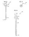
- FIG. 12is a side view of a cannula of the site of FIG. 1 .
- FIG. 13is an end view of the cannula of FIG. 13 .
- FIG. 14is cross-sectional view taken along line 14 - 14 of the cannula of FIG. 12 .
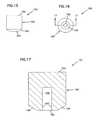
- FIG. 15is a side view of a diaphragm of the site of FIG. 1 .
- FIG. 16is an end view of the diaphragm of FIG. 15 .
- FIG. 17is a cross-sectional view taken along line 17 - 17 of the diaphragm of FIG. 16 .
- FIG. 18is a top view of an adhesive portion of the site of FIG. 1 .
- FIG. 19is a cross-sectional view taken along line 19 - 19 of the adhesive portion of FIG. 18 .
- FIG. 20is an exploded view of the adhesive portion of FIG. 18 .
- FIG. 21is a top perspective view of an example embodiment of a set in an unlocked position made in accordance with the present invention.
- FIG. 22is a top perspective view of a first member of the set of FIG. 21 .
- FIG. 23is a top view of the first member of FIG. 22 .
- FIG. 24is a side view of the first member of FIG. 22 .
- FIG. 25is an end view of the first member of FIG. 22 .
- FIG. 26is another end view of the first member of FIG. 22 .
- FIG. 27is a top perspective view of a second member of the set of FIG. 21 .
- FIG. 28is a top view of the second member of FIG. 27 .
- FIG. 29is a side view of the second member of FIG. 27 .
- FIG. 30is an end view of the second member of FIG. 27 .
- FIG. 31is another end view of the second member of FIG. 27 .
- FIG. 32is a top view of the set of FIG. 21 in an unlocked position.
- FIG. 33is a side view of the set of FIG. 32 .
- FIG. 34is an end view of the set of FIG. 32 .
- FIG. 35is a cross-sectional view taken along line 35 - 35 of the set of FIG. 32 with portions of the set removed for clarity.
- FIG. 36is a top perspective view of the set of FIG. 21 in a locked position.
- FIG. 37is a top view of the set of FIG. 36 .
- FIG. 38is a side view of the set of FIG. 36 .
- FIG. 39is an end view of the set of FIG. 36 .
- FIG. 40is a bottom perspective view of the set of FIG. 36 .
- FIG. 41is a bottom view of the set of FIG. 36 .
- FIG. 42is a cross-sectional view taken along line 42 - 42 of the set of FIG. 38 with portions of the set removed for clarity.
- FIG. 43is a perspective view of the site of FIG. 1 and the set of FIG. 21 coupled to one another.
- FIG. 44is a top view of the site and set of FIG. 43 .
- FIG. 45is a bottom view of the site and set of FIG. 43 .
- FIG. 46is a side view of the site and set of FIG. 43 .
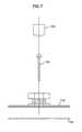
- FIG. 47is an end view of the site and set of FIG. 43 .
- FIG. 48is another end view of the site and set of FIG. 43 .
- FIG. 49is an exploded perspective view of the site and set of FIG. 43 .
- FIG. 50is a cross-sectional view taken along line 50 - 50 of the site and set of FIG. 44 .
- FIG. 51is an exploded perspective view of another example embodiment of an infusion device including a site and set made in accordance with the present invention.
- FIG. 52is a perspective view of the infusion device of FIG. 51 in a locked position.
- FIG. 53is a cross-sectional view of the site of FIG. 51 .
- FIG. 54is a side view of another embodiment of a cannula of a site.
- FIG. 55is a cross-sectional view taken along line 55 - 55 of the cannula of FIG. 54 .
- FIG. 56is an end view of the cannula of FIG. 54 .
- FIG. 57is a schematic view of another example cannula in an example site of a subcutaneous infusion device.
- Embodiments of the present inventionrelate to infusion devices for delivering a substance into the subcutaneous layer of skin of a patient.
- the example infusion devices disclosed hereininclude a site with a cannula that is introduced into the subcutaneous layer of the skin of a patient to deliver a substance, as well as a set that can be coupled to the site to deliver the substance to the site.
- FIGS. 1-7an example embodiment of a site 100 of an infusion device is depicted in accordance with the present invention.
- the site 100can be used in conjunction with a set (described below) to deliver a substance into a patient.
- the site 100includes a base 110 , a cannula 130 , a diaphragm 150 , and an adhesive portion 170 .
- the cannula 130 of the site 100can be introduced into the subcutaneous layer of skin of the patient using a needle (e.g., needle 139 ), as shown in FIG. 6A .
- the adhesive portion 170allows the base 110 of the site 100 to be coupled to the skin of the patient.
- the diaphragm 150is in fluid communication with the cannula to deliver a substance from the diaphragm 150 , through the cannula 130 , and into the skin of the patient, as described further below.
- the base 110includes a stand 114 with a top side 111 and a bottom side 112 , and forms a central aperture 113 located at a central axis C of the base 110 .
- the stand 114further forms eight positional slots 115 on the top side 111 positioned radially with respect to the central axis C of the site 110 at regular intervals.
- the base 110also includes a member 120 coupled to the stand 114 , the member 120 being positioned about the central aperture 113 of the stand 114 and including eight surfaces 124 .
- the member 120is non-cylindrical in shape.
- the member 120is octagonal in shape, although other shapes can also be used, as noted below.
- the non-cylindrical shape of member 120defines different mounting orientations for a set that can be coupled to the site 100 .
- An interior wall of the member 120forms a cylindrical cavity 121 , and an exterior periphery of the member 120 forms a groove 122 extending about the exterior periphery.
- the member 120forms eight apertures 123 extending from the interior cavity 121 to the groove 122 in the exterior of the member 120 .
- the cannula 130includes first and second ends 132 and 134 .
- the first end 132 of the cannula 130includes a flange portion 136 having a tapered bottom side 140 , as well as a tapered portion 138 described further below.
- the cannula 130also includes a central bore 142 extending from the first end 132 to the second end 134 to allow a substance to be introduced at the first end 132 and delivered out of the second end 134 .
- the cannula 130is positioned within the cavity 121 of the base 110 so that the bottom taper 140 of the cannula 130 engages tapered bottom surfaces 125 of the cavity 121 of the member 120 , and the second end 134 of the cannula 130 extends through the central aperture 113 of the stand 114 at an approximate right angle to the bottom side 112 of the stand 114 . See FIG. 6 .
- the bottom taper 140 of the cannula 130is positioned adjacent to the stand 114 of the base 110 .
- the cannula 130is made of fluorinated ethylene propylene (FEP).
- FEPfluorinated ethylene propylene
- Other materialscan also be used, such as polytetrafluoroethylene (PTFE), or other suitable plastics.
- the diaphragm 150functions as a septum or seal that allows a needle to access an internal portion of the septum to deliver a substance provided, for example, from an infusion device or other similar device to the cannula 130 .
- the diaphragm 150is generally cylindrical in shape and includes an open bottom end 152 and a closed top end 154 .
- the diaphragm 150also includes a tapered portion 156 adjacent the bottom end 152 , and a central reservoir 158 .
- the diaphragm 150is positioned in the cavity 121 of the member 120 and preferably includes an outer periphery 160 that is sized to frictionally engage the interior cavity wall of the member 120 to retain the diaphragm 150 in the cavity 121 .
- the tapered portion 156 of the diaphragm 150is configured to engage the tapered bottom surfaces 125 of the base 110 .
- the bottom end 152engages the first end 132 of the cannula 130 to provide fluid communication between the reservoir 158 and the bore 142 of the cannula 130 .
- surfaces 157 adjacent to the bottom end 152 of diaphragm 150preferably are compressed against the first end 132 of the cannula 130 to provide a seal with respect to the cannula 130 so a substance can be delivered from the diaphragm 150 , through the cannula 130 , and into the patient.
- additional structuresuch as, for example, an O-ring can also be provided between the diaphragm 150 and cannula 130 to provide additional sealing.
- the diaphragm 150is made of a silicone elastomer.
- Other materialscan also be used, such as ethylene propylene or other suitable elastomeric materials.
- the diaphragm 150is retained in the cavity 121 of the member 120 of the base 110 through the frictional engagement of the outer periphery 160 of the diaphragm 150 with the walls of the cavity 121 .
- a retaining membercan be fitted over the open top of the member 120 to further retain the diaphragm 150 in position in the cavity 121 .
- the diaphragm 150can be retained in the cavity 121 through compression by other features of the member 120 , or the diaphragm 150 can have features that mate with features of the member 120 .
- the diaphragm 150can be formed with barbs on the outer periphery 160 positioned and sized to be received within apertures 123 formed in the member 120 to retain the diaphragm 150 in the cavity 120 .
- Other configurationsare also possible.
- the adhesive portion 170includes liners 172 and 176 sandwiching a layer 174 .
- the layer 174includes an aperture 178 through which the cannula 130 of the site 100 extends, as described below.
- the liner 172can be removed and the layer 174 coupled to the bottom side 112 of the stand 114 of the base 110 using an adhesive.
- adhesivesinclude, without limitation, acrylic adhesive, synthetic rubber-based adhesive, acrylate adhesive, and silicone-based adhesive.
- the liner 176can be removed and an adhesive be provided on a bottom side of the layer 174 to couple the adhesive portion 170 and associated site 100 to another adhesive portion or the skin of the patient, for example.
- layer 174 of the adhesive portion 170includes films with adhesives thereon, such as and without limitation, 3MTM 1577 tape. Other materials can also be used.
- layer 174can be provided with a tab (not shown, but preferably similar to tabs shown on liners 172 and 176 ) or other similar structure that can assist the patient in removing the layer 174 and associated site 100 from the skin when desired.
- the tabcan extend from an outer periphery of the layer 174 and allow the patient to grasp the tab and thereby peel the layer 174 from the skin to remove the site 100 .
- the adhesive portion 170can be removed completely, and adhesion between the site 100 and skin of the patient can be provided using film and/or adhesive carried on other structures, such as a device used to insert the site 100 into the body, as described further below.
- the layer 174can include a foam backing or similar additional material can be added adjacent to the layer 174 to provide supplemental cushioning as the site 100 is inserted into the skin of the patient. Further, in other embodiments the layer 174 can be replaced or supplemented by one or more other layer of other material such as, for example, a TegadermTM film manufactured by 3MTM or an IV3000TM film manufactured by Smith & Nephew.
- FIG. 21an example embodiment of a set 200 of an infusion device is depicted in accordance with the present invention.
- the set 200can be used in conjunction with a site (e.g., site 100 ) to deliver a substance into a patient.
- the set 200generally includes a first member 210 and a second member 250 .
- the first member 210is slideable relative to the second member 250 into an unlocked position (see, e.g., FIGS. 21 and 32 - 35 ) and a locked position (see, e.g., FIGS. 36-42 ), described further below.
- the first member 210includes a main body 212 , and a port 213 extending through the body 212 and in fluid communication with a hollow needle 214 .
- the port 213is preferably coupled to a tube (e.g., tube 305 shown in FIG. 21 ) that can be attached, for example, to an infusion pump for the delivery of a substance to the set 200 .
- the first member 210also includes outer arms 220 and 222 with barbs 223 formed on the ends and projections 230 extending below the arms 220 .
- the first member 210includes inner arms 226 and 228 with barbs 229 .
- the outer arms 220 and 222can be displaced towards one another when force is applied to surfaces 221 .
- the second member 250includes a main body 260 , and a central octagonal aperture 270 .
- the second member 250also includes opening 262 extending to the central aperture 270 , as well as openings 264 positioned on opposite sides of the main body 260 .
- the second member 250also includes projections 266 formed on a bottom surface 274 of a base 261 , as well as slots 268 preferably extending through the base 261 of the main body 260 .
- first and second members 210 and 250 of the set 200are shown in the unlocked position.
- the first member 210is slidingly received by the second member 250 such that inner arms 226 and 228 are accepted into opening 262 of the second member 250 .
- Projections 230 on outer arms 220 and 222 of the first member 210are received in slots 268 of the second member 250 .
- barbs 229 of inner arms 226 and 228 of the first member 210extend through openings 264 and engage shoulders 271 of the second member 250 such that the first and second members 210 and 250 cannot be further separated.
- first and second members 210 and 250 of the set 200are shown in the locked position.
- the first and second members 210 and 250are slid towards one another, and outer arms 220 and 222 of the first member 210 are accepted into the openings 264 of the second member 250 .
- projections 230 on outer arms 220 and 222slide along slots 268 of the second member 250 .
- surfaces 234 of the inner arms 226 and 228partially extend into aperture 270 , as described further below.
- outer arms 220 and 222extend through openings 264 and engage lips 272 of the second member 250 .
- inner arms 226 and 228 of the first member 210extend further into the second member 250 .
- the engagement of the barbs 223 with the lips 272resist allowing the first member 210 from being slid relative to the second member 250 .
- the outer arms 220 and 222are deflected inwardly toward one another by applying pressure on surfaces 221 until the barbs 223 clear the lips 272 , thereby allowing the first member 210 to be slid with respect to the second member 250 back into the unlocked position as shown in FIGS. 21 and 32 - 35 .
- slots 268 formed in the second member 250include a cammed surface 269 so that projections 230 extending below the arms 220 of the first member 210 are biased towards a first end 267 of the slots 268 to thereby bias the first member 210 into the unlocked position. See FIGS. 40 and 41 .
- other featurescan be provided to bias the first member 210 into the unlocked position.
- detentscan be provided to engage barbs 229 as inner arms 226 and 228 of the first member 210 are moved towards the locked position to bias the first member 210 into the unlocked position. It can be preferable to bias the set 200 into the unlocked position so that the set 200 can be easily positioned onto and removed from the site 100 , as described further below.
- the site 100 and set 200can be used together to form an infusion device 300 for delivery of a substance to a patient.
- the site 100is positioned on the skin of a patient with the cannula 130 being introduced into the subcutaneous layer of the skin.
- Thiscan be accomplished, for example, using a needle (e.g., needle 130 shown in FIG. 6A ) that is extended through the exposed closed end 154 of the diaphragm 150 and through the bore 142 of the cannula 130 and beyond the second end 134 .
- the tapered portion 138 of the flange portion 136 of the cannula 130can assist in directing the needle through into the bore 142 of the cannula 130 .
- the needlecan be used to introduce the cannula 130 of the site 100 into the skin of the patient.
- the needlecan be removed, leaving the cannula 130 in place in the subcutaneous layer of the skin.
- the closed end 154 of the diaphragm 150reseals itself to retain the fluid-tight reservoir 158 .
- the site 100 of the infusion device 300is placed in position on the skin of a patient using a device made in accordance with that disclosed in U.S. patent application Ser. No. 10/705,725, entitled “Device and Method for Insertion of a Cannula of an Infusion Device,” filed on Nov. 10, 2003.
- Other methods and devices for inserting the infusion device into the skin of the patientcan also be used.
- the site 100can be inserted manually using a needle. See needle 139 shown in FIG. 6A .
- the set 200can be coupled to the site 100 as follows. With the set 200 in the unlocked position, the set 200 can be placed over the member 120 so that the central octagonal aperture 270 of the set 200 accepts the member 120 into the aperture 270 . The set 200 is lowered onto the site 100 until the bottom surface 274 of the set 200 contacts the stand 114 of the site 100 and projections 266 of the second member 250 are accepted into the positional slots 115 of the stand 114 of the base 110 .
- the first member 210 of the set 200can be slid from the unlocked to the locked position.
- surfaces 234 of the inner arms 226 and 228are accepted by the groove 112 of the member 120 of the base 100 , which locks the set 200 to the site 100 so that the set 200 resists any upward force tending to remove the set 200 from the site 100 when the set 200 is in the locked position.
- the shape of the member 120 of the site 100 and the central aperture 270 of the set 200 , as well as projections 266 received in slots 115orient the set 200 with respect to the site 100 and function to resist rotation of the set 200 with respect to the site 100 when the set 200 is in the locked position.
- the needle 214is advanced through one of the eight apertures 123 formed in the member 120 and into the diaphragm 150 in the cavity 121 .
- an end 215 of the needle 214is positioned within the reservoir 158 of the diaphragm 150 .
- the port 213is fluidly coupled to the cavity 121 of the diaphragm 150 through the hollow needle 214 , and the cavity 121 is in turn fluidly coupled to the skin of the patient through the bore 142 in the cannula 130 .
- a substancecan be delivered to the port 213 of the set 200 (by, for example, a tube not shown in the figures), through the needle 214 , into the reservoir 158 , and into the subcutaneous layer of the skin of the patient by the cannula 130 .
- the set 200can be moved from the locked to the unlocked position by forcing the outer arms 220 and 222 together and sliding the first member 210 away from the second member 250 to the unlocked position. This action removes the surfaces 234 from the groove 122 , as well as the needle 214 from the reservoir 158 .
- the diaphragm 150reseals upon removal of the needle 214 .
- the set 200can then be removed from the site 100 , leaving the site 100 in place on the skin of the patient.
- the set 200can be replaced at another orientation or at a later time.
- the set 200can be oriented in eight different positions with respect to the site 100 .
- the site 100 and set 200can be configured to include fewer or more positions as desired.
- the member 120 of the site 100 and the aperture 270 of the set 200can be formed in the shape of a square if four orientational positions are desired.
- FIGS. 51-53another example infusion device 400 is shown in accordance with the present invention.
- the device 400is similar to the example device 300 described above, except for the details noted below.
- the infusion device 400includes a site 405 with a central portion 407 .
- the central portion 407includes a pierceable outer shell 430 made of a material such as a plastic, and a softer inner diaphragm 432 surrounding the outer shell 430 .
- An inner reservoir 434 of the central portion 407is fluidly coupled to a cannula 440 . See FIG. 53 .
- the infusion device 400also includes a set with a first member 410 and a second member 420 .
- the first member 410includes a needle 411 , and first and second arms 412 and 414 with barbs 415 on ends.
- the second member 420includes shoulders 422 and 424 .
- the first and second members 410 and 420each form openings 461 and 426 , respectively, that are sized to each receive a portion of the central portion 407 of the site 405 .
- the infusion device 400can be used as follows. First, the site 405 is positioned on the skin of a patient so that the cannula 440 is introduced into the subcutaneous layer. Next, the first member 410 and second member 420 of the site are placed onto the site 405 so that openings 461 and 426 are positioned about the central portion 407 , and the first and second members 410 and 420 are slid towards one another from the unlocked to the locked position. As the set is moved to the locked position, the needle 411 is introduced into the central portion 407 of the site 405 , moving through the outer shell 430 and into the reservoir 434 to become fluidly coupled to the cannula 440 . In addition, the arms 412 and 414 are accepted into the second member 420 until barbs 415 engage the shoulders 422 and 424 in the locked position, as shown in FIG. 52 .
- the barbs 415are pressed inwardly toward one another until they clear the shoulders 422 and 424 , and then the first member 410 is slid away from the second member 420 , thereby removing the needle 411 from the central portion 407 of the site 405 .
- the setcan be oriented at an infinite number of rotational positions with respect to the site 405 as desired. Further, since the central portion 407 of the site and the openings 461 and 426 of the set are preferably circular in shape, the first and second members 410 and 420 of the site can be rotated relative to the site 405 without requiring that the set be completely removed from the site 405 .
- the cannula 530is similar to cannula 130 described above. See FIGS. 12-14 .
- the cannula 530includes first and second ends 532 and 534 .
- the first end 532includes a flange portion 536 having a tapered bottom side 540 , as well as a tapered portion 538 .
- the cannula 530also includes a central bore 542 extending from the first end 532 to the second end 534 to allow a substance to be introduced at the first end 532 and delivered out of the second end 534 .
- the cannula 530includes a tapered wall portion 550 extending from the tapered bottom side 540 .
- the tapered wall portion 550includes a first wall portion 552 positioned adjacent to the tapered bottom side 540 and a second wall portion 554 adjacent to a remaining distal portion 560 of the cannula 530 .
- the first wall portion 552is greater in radial thickness than the second wall portion 554 , so that the tapered wall portion 550 tapers as the tapered wall portion 550 extends from the tapered bottom side 540 to the distal portion 560 of the cannula 530 .
- a length L 1 of the cannula 530is approximately 9 millimeters. In another embodiment, the length L 1 is approximately 6 millimeters. In other alternatives, the length L 1 is approximately less than 9 millimeters, between 6 and 9 millimeters, less than 6 millimeters, 5 millimeters, 4 millimeters, 3 millimeters, less than 3 millimeters, 2 millimeters, or 1 millimeter.
- a difference in thickness L 2 between the first wall portion 552 and the second wall portion 554is approximately 1 millimeter.
- the dimension L 2is approximately 1.5 millimeters, less than 1.5 millimeters, 0.8 millimeters, 0.5 millimeters, or less than 0.5 millimeters.
- an axial length L 3 of the tapered wall portion 550is approximately 1.5 millimeters. In alternative embodiments, L 3 can be 3.0 millimeters, 2 millimeters, 1 millimeter, or less than 1 millimeter.
- L 1 , L 2 , and L 3 of the cannula 530can be used.
- the site 600includes a base 610 positionable relative to skin of a patient, and a cannula 620 extending from the base 610 and configured to be introduced into a subcutaneous layer of skin of the patient at a generally ninety-degree angle with respect to the skin using a needle.
- the cannula 620includes first and second ends 622 , 624 and defines a bore 626 extending from the first end 622 to the second end 624 , the first end 622 being coupled to the base 610 .
- the cannula 620includes a tapered wall portion 628 formed between the first and second ends 622 , 624 and extending from adjacent to the base 610 towards the second end 624 of the cannula 620 .
- the tapered wall portion 628is tapered from a greater wall thickness to a lesser wall thickness as the tapered wall portion 628 extends from the base 610 towards the second end 624 .
- the tapered wall portion 628is positioned outside the base 610 .
- the first end 622 of the cannula 620includes a tapered top side 630 opening into a reservoir 612 defined by the base 610 .
- the site 600can include: a base including a surface that is oriented towards skin of a patient; and a cannula extending from the surface of the base and configured to be introduced into a subcutaneous layer of skin of the patient at a generally ninety-degree angle with respect to the skin using a needle; wherein the cannula includes first and second ends and defines a bore extending from the first end to the second end, the first end being coupled to the base, and the second end being positionable in the skin; wherein the cannula includes a tapered wall portion formed at the first end and extending from adjacent to the surface of the base towards the second end of the cannula that is positionable in the skin, the tapered wall portion being tapered along its entirety from a greater wall thickness to a lesser wall thickness as the tapered wall portion extends from adjacent to the surface of the base towards the second end; and wherein the tapered wall portion extends outside the surface of the base into the skin and is spaced apart from the second end of the cannul
- the site 600can include: a base including a surface that is oriented towards skin of a patient; and a cannula extending from the base and configured to be introduced into a subcutaneous layer of skin of the patient using a needle; wherein the cannula includes first and second ends and defines a bore extending from the first end to the second end, the first end being coupled to the base, and the second end being positionable in the skin of the patient; wherein the cannula includes a tapered wall portion formed at the first end and extending from adjacent to the surface of the base towards the second end of the cannula, the tapered wall portion being tapered along its entirety from a greater wall thickness to a lesser wall thickness as the tapered wall portion extends through the base towards the second end positionable in the skin of the patient, and wherein the tapered wall portion extends outside the surface of the base into the skin and is spaced apart from the second end of the cannula that is positionable in the skin of the patient; and wherein a length of the cann
- the cannula 530is made of fluorinated ethylene propylene (FEP).
- FEPfluorinated ethylene propylene
- Other materialscan also be used, such as polytetrafluoroethylene (PTFE), or other suitable plastics.
- the added thickness of the tapered wall portion 550can function to minimize kinking or buckling of the cannula 530 during insertion into the subcutaneous layer of skin.
- the tapered wall portion 550can provide relief of the strain created between the tapered bottom side 540 and the remaining portion of the cannula 530 during use of the cannula 530 within the subcutaneous layer of skin.
- the tapering of the tapered wall portion 550can also function as a dilating plug within the skin to minimize drug delivered through the cannula 530 from migrating to the surface of the skin, where it may be less effective.
- the larger radial size of the first wall portion 552 of the portion 550can stretch the skin layers as it enters the skin, thereby creating a seal between the tapered wall portion 550 and the skin.
- the sealing properties of the tapered wall portion 550can be enhanced or replaced by applying an adhesive, hydro gel, or other similar material to the outer, upper surface of cannula 230 or 530 prior to insertion into the skin.
- the materialis a silicone elastomer that comprises dimethyl and methylvinyl siloxane copolymers and reinforcing silica.
- the adhesive, hydro gel, or other similar materialcan act to seal the cannula with the skin to form the necessary seal.
- This advantagecan be important for applications in which the length of the cannula is limited, such as for individuals having little subcutaneous tissue, such as a pediatric patient.
- the need for an effective seal between a cannula and the skinincreases as the length of the cannula decreases.
- the tapered wall portion 550allows for the use of a shorter cannula while still providing effective sealing between the cannula and the skin.
- the setcan be coupled in various selectable rotational orientations with respect to the site.
- a plurality of orientationscan be provided. This allows a patient to rotationally orient the set (and associated tube coupled to the set) as desired so that the tube can extend, for example, towards an infusion pump regardless of where the site is placed on the body of the patient.
- the set and associated tubecan be removed from the site multiple times while leaving the site on the skin. This can be desirable if the patient wants to reorient the set with respect to the site, or if the patient wants to remove the set from the site for a period of time, such as if the patient wishes to shower and then replace the set onto the site.
- the engagement of the set with the site and sliding action of the set from the unlocked to locked positioncan also be advantageous in that a patient can preferably accomplish orientation and coupling of the set to the site using a single hand. This can be preferable, for example, if the site has been placed on a portion of the body of the patient that is not easily reached using two hands, or cannot easily be seen by the patient (e.g., if the site is placed on the back of the patient).
- the configuration of the setfunctions to protect the patient from inadvertent contact with the hollow needle (e.g., needles 214 and 411 ) used to pierce the diaphragm and deliver the substance to the site.
- the outer arms 220 and 222 and the inner arms 226 and 228 of the first member 210 of the set 200generally surround the needle 214 and function to reduce the chance that the patient will inadvertently contact the needle.
- the configuration of the diaphragm in the sitecan be preferable in that a single diaphragm can function to both allow introduction of the cannula of the site into the body using one needle, as well as coupling of the set with the site using a second needle.
- the diaphragmcan preferably be held within the site through frictional engagement between the diaphragm and the site without requiring additional structure to retain the diaphragm in the site.
- infusion deviceshave been described herein, various modifications can be made to the devices.
- the member 120 of the site 100 and the aperture 270 of the set 200can be formed in a variety of shapes to allow the set 200 to be oriented in multiple positions with respect to the site 100 .
- a retaining membercan be fitted over the open top of the member 120 to further retain the diaphragm 150 in position in the cavity 121 .
- site 100including cannula 230 or 530 , can be configured as an angled site, rather than a ninety-degree or right angled site. In these embodiments, the site is introduced into the skin at an angle other than ninety-degrees, rather than being introduced at a generally right angle.
- the second member 250 of the set 200can be constructed to include a cover portion extending from the main body 260 so that when the set 200 is moved to the locked position the cover extends over the closed end 154 of the diaphragm 150 to reduce exposure of the set and site to outside contaminants.
Landscapes
- Health & Medical Sciences (AREA)
- Vascular Medicine (AREA)
- Engineering & Computer Science (AREA)
- Anesthesiology (AREA)
- Biomedical Technology (AREA)
- Heart & Thoracic Surgery (AREA)
- Hematology (AREA)
- Life Sciences & Earth Sciences (AREA)
- Animal Behavior & Ethology (AREA)
- General Health & Medical Sciences (AREA)
- Public Health (AREA)
- Veterinary Medicine (AREA)
- Infusion, Injection, And Reservoir Apparatuses (AREA)
Abstract
Description
Claims (12)
Priority Applications (1)
| Application Number | Priority Date | Filing Date | Title |
|---|---|---|---|
| US11/554,835US7993306B2 (en) | 2006-10-31 | 2006-10-31 | Subcutaneous infusion device and method including tapered cannula |
Applications Claiming Priority (1)
| Application Number | Priority Date | Filing Date | Title |
|---|---|---|---|
| US11/554,835US7993306B2 (en) | 2006-10-31 | 2006-10-31 | Subcutaneous infusion device and method including tapered cannula |
Publications (2)
| Publication Number | Publication Date |
|---|---|
| US20080103450A1 US20080103450A1 (en) | 2008-05-01 |
| US7993306B2true US7993306B2 (en) | 2011-08-09 |
Family
ID=39331210
Family Applications (1)
| Application Number | Title | Priority Date | Filing Date |
|---|---|---|---|
| US11/554,835Expired - Fee RelatedUS7993306B2 (en) | 2006-10-31 | 2006-10-31 | Subcutaneous infusion device and method including tapered cannula |
Country Status (1)
| Country | Link |
|---|---|
| US (1) | US7993306B2 (en) |
Cited By (19)
| Publication number | Priority date | Publication date | Assignee | Title |
|---|---|---|---|---|
| US20090264825A1 (en)* | 2003-11-10 | 2009-10-22 | Smiths Medical Md, Inc. | Subcutaneous Infusion Device and Device for Insertion of a Cannula of an Infusion Device and Method |
| US20110028982A1 (en)* | 2009-07-29 | 2011-02-03 | Smiths Medical Asd, Inc. | Device for Insertion of a Cannula of an Infusion Device and Method |
| US8287495B2 (en) | 2009-07-30 | 2012-10-16 | Tandem Diabetes Care, Inc. | Infusion pump system with disposable cartridge having pressure venting and pressure feedback |
| US8486024B2 (en) | 2011-04-27 | 2013-07-16 | Covidien Lp | Safety IV catheter assemblies |
| US8628497B2 (en) | 2011-09-26 | 2014-01-14 | Covidien Lp | Safety catheter |
| US8715250B2 (en) | 2011-09-26 | 2014-05-06 | Covidien Lp | Safety catheter and needle assembly |
| US8834422B2 (en) | 2011-10-14 | 2014-09-16 | Covidien Lp | Vascular access assembly and safety device |
| US8939938B2 (en) | 2006-10-12 | 2015-01-27 | Covidien Lp | Needle tip protector |
| US9795777B2 (en) | 2011-12-07 | 2017-10-24 | Becton, Dickinson And Company | Infusion device with releasable fluid connector |
| USD806241S1 (en) | 2016-07-07 | 2017-12-26 | Becton, Dickinson And Company | Septum seal |
| US9889255B2 (en) | 2011-12-07 | 2018-02-13 | Becton, Dickinson And Company | Needle shielding assemblies and infusion devices for use therewith |
| US9962486B2 (en) | 2013-03-14 | 2018-05-08 | Tandem Diabetes Care, Inc. | System and method for detecting occlusions in an infusion pump |
| US10258736B2 (en) | 2012-05-17 | 2019-04-16 | Tandem Diabetes Care, Inc. | Systems including vial adapter for fluid transfer |
| WO2020219393A3 (en)* | 2019-04-20 | 2021-01-07 | Biolark, Inc. | An infusion set having reduced patient pain |
| US11229753B2 (en) | 2016-04-29 | 2022-01-25 | Smiths Medical Asd, Inc. | Subcutaneous insertion systems, devices and related methods |
| USD1013864S1 (en) | 2021-08-26 | 2024-02-06 | Deka Products Limited Partnership | Fluid administration apparatus assembly |
| USD1043976S1 (en) | 2022-08-26 | 2024-09-24 | Deka Products Limited Partnership | Fluid transfer connector |
| USD1057941S1 (en) | 2022-08-26 | 2025-01-14 | Deka Products Limited Partnership | Patient care assembly component |
| USD1090862S1 (en) | 2022-08-26 | 2025-08-26 | Deka Products Limited Partnership | Adhering assembly for medical devices and the like |
Families Citing this family (3)
| Publication number | Priority date | Publication date | Assignee | Title |
|---|---|---|---|---|
| US10220137B2 (en)* | 2012-07-31 | 2019-03-05 | Becton, Dickinson And Company | Subcutaneous infusion set with side port fluid connector |
| US9757515B1 (en)* | 2013-10-16 | 2017-09-12 | Flextronics Ap, Llc | Multi-location top loading insulin infusion set |
| US20220401644A1 (en)* | 2021-06-18 | 2022-12-22 | Medtronic Minimed, Inc. | Irremovable buckling-resistant flexible cannula and process |
Citations (80)
| Publication number | Priority date | Publication date | Assignee | Title |
|---|---|---|---|---|
| US3547119A (en) | 1967-12-08 | 1970-12-15 | Baxter Laboratories Inc | Catheter assembly |
| US4531937A (en) | 1983-01-24 | 1985-07-30 | Pacesetter Systems, Inc. | Introducer catheter apparatus and method of use |
| US4563177A (en) | 1983-12-22 | 1986-01-07 | Kamen Dean L | Catheter stabilization pad |
| US4755173A (en) | 1986-02-25 | 1988-07-05 | Pacesetter Infusion, Ltd. | Soft cannula subcutaneous injection set |
| EP0290176A1 (en) | 1987-04-29 | 1988-11-09 | Phase Medical, Inc. | Cannula insertion set with safety retracting needle |
| US4994042A (en) | 1989-10-02 | 1991-02-19 | Vadher Dinesh L | Combined catheter and needle |
| EP0239244B1 (en) | 1986-02-25 | 1991-09-18 | Pacesetter Infusion Ltd. | Subcutaneous injection set |
| EP0451040A1 (en) | 1990-04-03 | 1991-10-09 | Robert L. Parker | Closed system intravenous catheter |
| US5092853A (en) | 1991-02-04 | 1992-03-03 | Couvertier Ii Douglas | Automatic retractable medical needle and method |
| US5129884A (en) | 1990-01-16 | 1992-07-14 | Dysarz Edward D | Trap in barrel one handed retracted intervenous catheter device |
| US5135496A (en) | 1989-05-17 | 1992-08-04 | Arzneimittel Gmbh Apotheker Vetter & Co. | Tamper-proof hypodermic syringe assembly |
| US5137516A (en) | 1989-11-28 | 1992-08-11 | Glaxo Group Limited | Triggered application device for medicament to be more descriptive of the invention |
| US5176650A (en) | 1992-02-10 | 1993-01-05 | Haining Michael L | Intravenous catheter and insertion device |
| US5176662A (en) | 1990-08-23 | 1993-01-05 | Minimed Technologies, Ltd. | Subcutaneous injection set with improved cannula mounting arrangement |
| US5257980A (en) | 1993-04-05 | 1993-11-02 | Minimed Technologies, Ltd. | Subcutaneous injection set with crimp-free soft cannula |
| US5451210A (en) | 1991-04-29 | 1995-09-19 | Lifequest Medical, Inc. | System and method for rapid vascular drug delivery |
| US5522803A (en) | 1993-03-09 | 1996-06-04 | Pharma Plast International A/S | Infusion set for an intermittent or continuous administration of a therapeutical substance |
| US5545143A (en) | 1993-01-21 | 1996-08-13 | T. S. I. Medical | Device for subcutaneous medication delivery |
| WO1996032981A1 (en) | 1995-04-17 | 1996-10-24 | Med Design Corporation | Safety stylet for intravenous catheter insertion |
| US5573510A (en) | 1994-02-28 | 1996-11-12 | Isaacson; Dennis R. | Safety intravenous catheter assembly with automatically retractable needle |
| US5575777A (en) | 1993-11-15 | 1996-11-19 | Becton Dickinson And Company | Retractable needle cannula insertion set with refinements to better control leakage, retraction speed and reuse |
| US5584813A (en) | 1995-06-07 | 1996-12-17 | Minimed Inc. | Subcutaneous injection set |
| US5591188A (en) | 1994-04-12 | 1997-01-07 | Wais-Med Lmt, A Subsidiary Company Of Teic Technion Enterpreneurial Incubator Ltd. | Surgical instrument for impact insertion of an intraosseous trocar-needle |
| US5676156A (en) | 1991-08-14 | 1997-10-14 | Yoon; Inbae | Automatic retractable safety penetrating instrument |
| US5738641A (en) | 1996-07-31 | 1998-04-14 | Watson; Robert L. | Blood withdrawal patch |
| US5817058A (en) | 1996-12-23 | 1998-10-06 | Shaw; Thomas J. | Retractable catheter introducer structure |
| US5833666A (en) | 1993-11-23 | 1998-11-10 | Uresil Corporation | Catheter fixation assembly |
| US5848990A (en) | 1993-10-22 | 1998-12-15 | Hoffmann-La Roche Inc. | Device for introducing active substance into a patient |
| US5848989A (en)* | 1997-06-05 | 1998-12-15 | Davinci Biomedical Research Products, Inc. | Implantable port with low profile housing for delivery/collection of fluids and implantation method |
| US5851197A (en) | 1997-02-05 | 1998-12-22 | Minimed Inc. | Injector for a subcutaneous infusion set |
| US5947931A (en) | 1989-07-24 | 1999-09-07 | Venetec International, Inc. | Tube fitting anchoring system |
| DE29905072U1 (en) | 1998-03-20 | 1999-09-09 | Maersk Medical A/S, Lynge | Subcutaneous infusion device |
| US5968011A (en) | 1997-06-20 | 1999-10-19 | Maersk Medical A/S | Subcutaneous injection set |
| US5980506A (en) | 1998-03-20 | 1999-11-09 | Mathiasen; Orla | Subcutaneous infusion device |
| US6056718A (en) | 1998-03-04 | 2000-05-02 | Minimed Inc. | Medication infusion set |
| US6077244A (en) | 1998-04-30 | 2000-06-20 | Mdc Investment Holdings, Inc. | Catheter insertion device with retractable needle |
| US6086575A (en) | 1998-03-20 | 2000-07-11 | Maersk Medical A/S | Subcutaneous infusion device |
| US6093172A (en) | 1997-02-05 | 2000-07-25 | Minimed Inc. | Injector for a subcutaneous insertion set |
| US6123690A (en) | 1998-03-20 | 2000-09-26 | Maersk Medical A/S | Subcutaneous infusion device |
| US6159181A (en) | 1998-04-18 | 2000-12-12 | Owen Mumford Limited Of Brook Hill | Injection device |
| US6191338B1 (en) | 1998-11-19 | 2001-02-20 | Kurt Haller | Adhesive bandage, matrix, and methods of removal |
| US6293925B1 (en) | 1997-12-31 | 2001-09-25 | Minimed Inc. | Insertion device for an insertion set and method of using the same |
| US6302866B1 (en) | 1998-05-14 | 2001-10-16 | Disetronic Licensing Ag | Catheter head for subcutaneous administration of an substance |
| US20010053889A1 (en) | 1998-05-14 | 2001-12-20 | Rolf Marggi | Catheter head for subcutaneous administration of an active substance |
| US6355021B1 (en) | 1998-07-14 | 2002-03-12 | Maersk Medical A/S | Medical puncturing device |
| US20020077599A1 (en) | 2000-12-19 | 2002-06-20 | Animas Corporation | Transcutaneous inserter for low-profile infusion sets |
| US6450992B1 (en) | 1999-07-02 | 2002-09-17 | Smith & Nephew, Inc. | Cannula interface |
| WO2002081012A2 (en) | 2001-04-06 | 2002-10-17 | Disetronic Licensing Ag | Infusion set |
| US20020161332A1 (en) | 2001-04-13 | 2002-10-31 | Kirk Ramey | Infusion set with tape |
| US20020173769A1 (en) | 2001-05-18 | 2002-11-21 | Gray Larry B. | Infusion set for a fluid pump |
| WO2002102442A1 (en) | 2001-06-14 | 2002-12-27 | Occupational & Medical Innovations Ltd | A retractable needle assembly for a catheter and which uses an elastomeric member to retract the needle |
| US20030014018A1 (en) | 2000-08-02 | 2003-01-16 | Lucio Giambattista | Pen needle and safety shield system |
| US20030060781A1 (en) | 2001-09-27 | 2003-03-27 | Mogensen Lasse Wesseltoft | Injector device for placing a subcutaneous infusion set |
| US6572586B1 (en) | 2000-07-25 | 2003-06-03 | Animas Corporation | Low profile infusion set |
| US20030109829A1 (en) | 2001-09-28 | 2003-06-12 | Mogensen Lasse Wesseltoft | Injector device for placing a subcutaneous infusion set |
| US6579267B2 (en) | 2001-01-05 | 2003-06-17 | Applied Diabetes Research, Inc. | Pivoting joint infusion assembly |
| US20030125669A1 (en) | 1997-02-05 | 2003-07-03 | Minimed Inc. | Insertion device for an insertion set and method of using the same |
| US20030158520A1 (en) | 1997-02-05 | 2003-08-21 | Medtronic Minimed, Inc. | Insertion device for an insertion set and method of using the same |
| US6620136B1 (en) | 1999-02-18 | 2003-09-16 | Medsafe Technologies, Llc | Retractable I-V catheter placement device |
| DE20220543U1 (en) | 2002-11-29 | 2003-10-02 | Disetronic Licensing Ag, Burgdorf | Catheter head for medical and pharmaceutical use comprises cannula fitted with seal and connected by a fluid channel to catheter connection |
| US20030225374A1 (en) | 2002-02-12 | 2003-12-04 | Orla Mathiasen | Infusion device with needle shield |
| US20040002682A1 (en) | 1997-02-05 | 2004-01-01 | Medtronic Minimed, Inc. | Insertion device for an insertion set and method of using the same |
| US6685674B2 (en) | 2001-03-04 | 2004-02-03 | Sterling Medivations, Inc. | Infusion hub assembly and fluid line disconnect system |
| US6736797B1 (en) | 1998-06-19 | 2004-05-18 | Unomedical A/S | Subcutaneous infusion set |
| US6749589B1 (en) | 2000-01-18 | 2004-06-15 | Sterling Medications, Inc. | Subcutaneous injection set for use with a reservoir that has a septum |
| US20040143216A1 (en) | 2002-08-30 | 2004-07-22 | Spectrx, Inc. | Adapter connector for an infusion set and inserter system |
| US20040147877A1 (en)* | 2003-01-27 | 2004-07-29 | Heuser Richard R | Catheter introducer system |
| US20040199123A1 (en) | 2003-04-01 | 2004-10-07 | Nielsen Jens Egebjerg | Infusion device and an adhesive sheet material and a release liner |
| US20040236284A1 (en) | 2001-06-08 | 2004-11-25 | Hoste Shannon Marie-Lynn | Needle hiding assembly for a medication injector |
| US20040260250A1 (en) | 2003-06-18 | 2004-12-23 | Harris R. Bradley | Infusion device with safety guard |
| US20050075606A1 (en) | 1998-07-31 | 2005-04-07 | Michael Botich | Retractable needle medical device |
| US20050090779A1 (en)* | 2002-03-15 | 2005-04-28 | Osypka Thomas P. | Locking vascular introducer assembly with adjustable hemostatic seal |
| US20050101933A1 (en)* | 2003-11-10 | 2005-05-12 | James Marrs | Subcutaneous infusion device and method |
| US20050101910A1 (en) | 2003-11-10 | 2005-05-12 | Medtronic Minimed, Inc. | Subcutaneous infusion set |
| US20050107743A1 (en)* | 2003-11-18 | 2005-05-19 | Fangrow Thomas F.Jr. | Infusion set |
| US20050131346A1 (en) | 2002-02-26 | 2005-06-16 | Douglas Joel S. | Insertion device for an insertion set and method of using the same |
| US6926694B2 (en) | 2003-05-09 | 2005-08-09 | Medsolve Technologies, Llc | Apparatus and method for delivery of therapeutic and/or diagnostic agents |
| US20060041224A1 (en) | 2003-02-12 | 2006-02-23 | Unomedical A/S | Cover |
| US7018344B2 (en) | 2003-01-21 | 2006-03-28 | Becton, Dickinson And Company | Retractable needle shielding device |
| US20060173413A1 (en) | 2004-12-21 | 2006-08-03 | Taiject Medical Device Co., Ltd. | Intravenous catheter insertion device with retractable needle |
Family Cites Families (3)
| Publication number | Priority date | Publication date | Assignee | Title |
|---|---|---|---|---|
| JP3868508B2 (en)* | 1993-01-29 | 2007-01-17 | 日本ゼオン株式会社 | Press-through package |
| US6302566B1 (en)* | 1999-07-21 | 2001-10-16 | Richard Cohon | Removable lampshade drape |
| TWI283143B (en)* | 2002-12-03 | 2007-06-21 | Au Optronics Corp | Structure and method for reducing the resistance of power line, suitable for use in a LED displayer |
- 2006
- 2006-10-31USUS11/554,835patent/US7993306B2/ennot_activeExpired - Fee Related
Patent Citations (95)
| Publication number | Priority date | Publication date | Assignee | Title |
|---|---|---|---|---|
| US3547119A (en) | 1967-12-08 | 1970-12-15 | Baxter Laboratories Inc | Catheter assembly |
| US4531937A (en) | 1983-01-24 | 1985-07-30 | Pacesetter Systems, Inc. | Introducer catheter apparatus and method of use |
| US4563177A (en) | 1983-12-22 | 1986-01-07 | Kamen Dean L | Catheter stabilization pad |
| US4755173A (en) | 1986-02-25 | 1988-07-05 | Pacesetter Infusion, Ltd. | Soft cannula subcutaneous injection set |
| EP0239244B1 (en) | 1986-02-25 | 1991-09-18 | Pacesetter Infusion Ltd. | Subcutaneous injection set |
| EP0290176A1 (en) | 1987-04-29 | 1988-11-09 | Phase Medical, Inc. | Cannula insertion set with safety retracting needle |
| US5135496A (en) | 1989-05-17 | 1992-08-04 | Arzneimittel Gmbh Apotheker Vetter & Co. | Tamper-proof hypodermic syringe assembly |
| US5947931A (en) | 1989-07-24 | 1999-09-07 | Venetec International, Inc. | Tube fitting anchoring system |
| US4994042A (en) | 1989-10-02 | 1991-02-19 | Vadher Dinesh L | Combined catheter and needle |
| US5137516A (en) | 1989-11-28 | 1992-08-11 | Glaxo Group Limited | Triggered application device for medicament to be more descriptive of the invention |
| US5129884A (en) | 1990-01-16 | 1992-07-14 | Dysarz Edward D | Trap in barrel one handed retracted intervenous catheter device |
| EP0451040A1 (en) | 1990-04-03 | 1991-10-09 | Robert L. Parker | Closed system intravenous catheter |
| US5176662A (en) | 1990-08-23 | 1993-01-05 | Minimed Technologies, Ltd. | Subcutaneous injection set with improved cannula mounting arrangement |
| US5092853A (en) | 1991-02-04 | 1992-03-03 | Couvertier Ii Douglas | Automatic retractable medical needle and method |
| US5451210A (en) | 1991-04-29 | 1995-09-19 | Lifequest Medical, Inc. | System and method for rapid vascular drug delivery |
| US5676156A (en) | 1991-08-14 | 1997-10-14 | Yoon; Inbae | Automatic retractable safety penetrating instrument |
| US5176650A (en) | 1992-02-10 | 1993-01-05 | Haining Michael L | Intravenous catheter and insertion device |
| US6017328A (en) | 1993-01-21 | 2000-01-25 | Magnolia Medical, Llc | Device for subcutaneous medication delivery |
| EP0615768B1 (en) | 1993-01-21 | 1999-12-15 | Robert E. Fischell | Device for subcutaneous medication delivery |
| US5545143A (en) | 1993-01-21 | 1996-08-13 | T. S. I. Medical | Device for subcutaneous medication delivery |
| US5522803A (en) | 1993-03-09 | 1996-06-04 | Pharma Plast International A/S | Infusion set for an intermittent or continuous administration of a therapeutical substance |
| US5257980A (en) | 1993-04-05 | 1993-11-02 | Minimed Technologies, Ltd. | Subcutaneous injection set with crimp-free soft cannula |
| US5848990A (en) | 1993-10-22 | 1998-12-15 | Hoffmann-La Roche Inc. | Device for introducing active substance into a patient |
| US5575777A (en) | 1993-11-15 | 1996-11-19 | Becton Dickinson And Company | Retractable needle cannula insertion set with refinements to better control leakage, retraction speed and reuse |
| US5833666A (en) | 1993-11-23 | 1998-11-10 | Uresil Corporation | Catheter fixation assembly |
| US5573510A (en) | 1994-02-28 | 1996-11-12 | Isaacson; Dennis R. | Safety intravenous catheter assembly with automatically retractable needle |
| US6056726A (en) | 1994-02-28 | 2000-05-02 | Isaacson; Dennis Ray | Self-contained safety intravenous catheter insertion device |
| US5591188A (en) | 1994-04-12 | 1997-01-07 | Wais-Med Lmt, A Subsidiary Company Of Teic Technion Enterpreneurial Incubator Ltd. | Surgical instrument for impact insertion of an intraosseous trocar-needle |
| WO1996032981A1 (en) | 1995-04-17 | 1996-10-24 | Med Design Corporation | Safety stylet for intravenous catheter insertion |
| US5584813A (en) | 1995-06-07 | 1996-12-17 | Minimed Inc. | Subcutaneous injection set |
| US5738641A (en) | 1996-07-31 | 1998-04-14 | Watson; Robert L. | Blood withdrawal patch |
| US5817058A (en) | 1996-12-23 | 1998-10-06 | Shaw; Thomas J. | Retractable catheter introducer structure |
| US20040002682A1 (en) | 1997-02-05 | 2004-01-01 | Medtronic Minimed, Inc. | Insertion device for an insertion set and method of using the same |
| US5851197A (en) | 1997-02-05 | 1998-12-22 | Minimed Inc. | Injector for a subcutaneous infusion set |
| US20030158520A1 (en) | 1997-02-05 | 2003-08-21 | Medtronic Minimed, Inc. | Insertion device for an insertion set and method of using the same |
| US20030225373A1 (en) | 1997-02-05 | 2003-12-04 | Minimed, Inc. | Insertion device for an insertion set and method of using the same |
| US6093172A (en) | 1997-02-05 | 2000-07-25 | Minimed Inc. | Injector for a subcutaneous insertion set |
| US20030130619A1 (en) | 1997-02-05 | 2003-07-10 | Medtronic Minimed, Inc. | Insertion device for an insertion set and method of using the same |
| US20030125669A1 (en) | 1997-02-05 | 2003-07-03 | Minimed Inc. | Insertion device for an insertion set and method of using the same |
| US5848989A (en)* | 1997-06-05 | 1998-12-15 | Davinci Biomedical Research Products, Inc. | Implantable port with low profile housing for delivery/collection of fluids and implantation method |
| US5968011A (en) | 1997-06-20 | 1999-10-19 | Maersk Medical A/S | Subcutaneous injection set |
| US6293925B1 (en) | 1997-12-31 | 2001-09-25 | Minimed Inc. | Insertion device for an insertion set and method of using the same |
| US20030199823A1 (en) | 1997-12-31 | 2003-10-23 | Minimed Inc. | Insertion device for an insertion set and method of using the same |
| US6607509B2 (en) | 1997-12-31 | 2003-08-19 | Medtronic Minimed, Inc. | Insertion device for an insertion set and method of using the same |
| US6056718A (en) | 1998-03-04 | 2000-05-02 | Minimed Inc. | Medication infusion set |
| US6520938B1 (en) | 1998-03-04 | 2003-02-18 | Medtronic Minimed, Inc. | Medication infusion set |
| US6123690A (en) | 1998-03-20 | 2000-09-26 | Maersk Medical A/S | Subcutaneous infusion device |
| US6086575A (en) | 1998-03-20 | 2000-07-11 | Maersk Medical A/S | Subcutaneous infusion device |
| US5980506A (en) | 1998-03-20 | 1999-11-09 | Mathiasen; Orla | Subcutaneous infusion device |
| DE29905072U1 (en) | 1998-03-20 | 1999-09-09 | Maersk Medical A/S, Lynge | Subcutaneous infusion device |
| US6159181A (en) | 1998-04-18 | 2000-12-12 | Owen Mumford Limited Of Brook Hill | Injection device |
| US6077244A (en) | 1998-04-30 | 2000-06-20 | Mdc Investment Holdings, Inc. | Catheter insertion device with retractable needle |
| US20010053889A1 (en) | 1998-05-14 | 2001-12-20 | Rolf Marggi | Catheter head for subcutaneous administration of an active substance |
| US6302866B1 (en) | 1998-05-14 | 2001-10-16 | Disetronic Licensing Ag | Catheter head for subcutaneous administration of an substance |
| US6736797B1 (en) | 1998-06-19 | 2004-05-18 | Unomedical A/S | Subcutaneous infusion set |
| US20020045867A1 (en) | 1998-07-14 | 2002-04-18 | Maersk Medical A/S | Medical puncturing device |
| US6355021B1 (en) | 1998-07-14 | 2002-03-12 | Maersk Medical A/S | Medical puncturing device |
| US20050075606A1 (en) | 1998-07-31 | 2005-04-07 | Michael Botich | Retractable needle medical device |
| US6191338B1 (en) | 1998-11-19 | 2001-02-20 | Kurt Haller | Adhesive bandage, matrix, and methods of removal |
| US6620136B1 (en) | 1999-02-18 | 2003-09-16 | Medsafe Technologies, Llc | Retractable I-V catheter placement device |
| US6450992B1 (en) | 1999-07-02 | 2002-09-17 | Smith & Nephew, Inc. | Cannula interface |
| US6749589B1 (en) | 2000-01-18 | 2004-06-15 | Sterling Medications, Inc. | Subcutaneous injection set for use with a reservoir that has a septum |
| US6572586B1 (en) | 2000-07-25 | 2003-06-03 | Animas Corporation | Low profile infusion set |
| US20030014018A1 (en) | 2000-08-02 | 2003-01-16 | Lucio Giambattista | Pen needle and safety shield system |
| US7052483B2 (en) | 2000-12-19 | 2006-05-30 | Animas Corporation | Transcutaneous inserter for low-profile infusion sets |
| US20020077599A1 (en) | 2000-12-19 | 2002-06-20 | Animas Corporation | Transcutaneous inserter for low-profile infusion sets |
| US6579267B2 (en) | 2001-01-05 | 2003-06-17 | Applied Diabetes Research, Inc. | Pivoting joint infusion assembly |
| US6685674B2 (en) | 2001-03-04 | 2004-02-03 | Sterling Medivations, Inc. | Infusion hub assembly and fluid line disconnect system |
| US20040158207A1 (en) | 2001-04-06 | 2004-08-12 | Marcel Hunn | Infusion set |
| WO2002081012A2 (en) | 2001-04-06 | 2002-10-17 | Disetronic Licensing Ag | Infusion set |
| US20020161332A1 (en) | 2001-04-13 | 2002-10-31 | Kirk Ramey | Infusion set with tape |
| US20020173769A1 (en) | 2001-05-18 | 2002-11-21 | Gray Larry B. | Infusion set for a fluid pump |
| US20040236284A1 (en) | 2001-06-08 | 2004-11-25 | Hoste Shannon Marie-Lynn | Needle hiding assembly for a medication injector |
| WO2002102442A1 (en) | 2001-06-14 | 2002-12-27 | Occupational & Medical Innovations Ltd | A retractable needle assembly for a catheter and which uses an elastomeric member to retract the needle |
| US20040204687A1 (en) | 2001-09-27 | 2004-10-14 | Mogensen Lasse Wesseltoft | Injector device for placing a subcutaneous infusion set |
| US20030060781A1 (en) | 2001-09-27 | 2003-03-27 | Mogensen Lasse Wesseltoft | Injector device for placing a subcutaneous infusion set |
| US6830562B2 (en) | 2001-09-27 | 2004-12-14 | Unomedical A/S | Injector device for placing a subcutaneous infusion set |
| US20050043687A1 (en) | 2001-09-27 | 2005-02-24 | Mogensen Lasse Wesseltoft | Injector device for placing a subcutaneous infusion set |
| US20030109829A1 (en) | 2001-09-28 | 2003-06-12 | Mogensen Lasse Wesseltoft | Injector device for placing a subcutaneous infusion set |
| US20030225374A1 (en) | 2002-02-12 | 2003-12-04 | Orla Mathiasen | Infusion device with needle shield |
| US7056302B2 (en) | 2002-02-26 | 2006-06-06 | Sterling Medivations, Inc. | Insertion device for an insertion set and method of using the same |
| US20050131346A1 (en) | 2002-02-26 | 2005-06-16 | Douglas Joel S. | Insertion device for an insertion set and method of using the same |
| US20050090779A1 (en)* | 2002-03-15 | 2005-04-28 | Osypka Thomas P. | Locking vascular introducer assembly with adjustable hemostatic seal |
| US20040143216A1 (en) | 2002-08-30 | 2004-07-22 | Spectrx, Inc. | Adapter connector for an infusion set and inserter system |
| DE20220543U1 (en) | 2002-11-29 | 2003-10-02 | Disetronic Licensing Ag, Burgdorf | Catheter head for medical and pharmaceutical use comprises cannula fitted with seal and connected by a fluid channel to catheter connection |
| US7018344B2 (en) | 2003-01-21 | 2006-03-28 | Becton, Dickinson And Company | Retractable needle shielding device |
| US20040147877A1 (en)* | 2003-01-27 | 2004-07-29 | Heuser Richard R | Catheter introducer system |
| US20060041224A1 (en) | 2003-02-12 | 2006-02-23 | Unomedical A/S | Cover |
| US20040199123A1 (en) | 2003-04-01 | 2004-10-07 | Nielsen Jens Egebjerg | Infusion device and an adhesive sheet material and a release liner |
| US6926694B2 (en) | 2003-05-09 | 2005-08-09 | Medsolve Technologies, Llc | Apparatus and method for delivery of therapeutic and/or diagnostic agents |
| US20040260250A1 (en) | 2003-06-18 | 2004-12-23 | Harris R. Bradley | Infusion device with safety guard |
| US20050101933A1 (en)* | 2003-11-10 | 2005-05-12 | James Marrs | Subcutaneous infusion device and method |
| US20050101910A1 (en) | 2003-11-10 | 2005-05-12 | Medtronic Minimed, Inc. | Subcutaneous infusion set |
| US20050107743A1 (en)* | 2003-11-18 | 2005-05-19 | Fangrow Thomas F.Jr. | Infusion set |
| US20060173413A1 (en) | 2004-12-21 | 2006-08-03 | Taiject Medical Device Co., Ltd. | Intravenous catheter insertion device with retractable needle |
Cited By (38)
| Publication number | Priority date | Publication date | Assignee | Title |
|---|---|---|---|---|
| US20090264825A1 (en)* | 2003-11-10 | 2009-10-22 | Smiths Medical Md, Inc. | Subcutaneous Infusion Device and Device for Insertion of a Cannula of an Infusion Device and Method |
| US9192717B2 (en) | 2003-11-10 | 2015-11-24 | Smiths Medical Asd, Inc. | Subcutaneous infusion device and device for insertion of a cannula of an infusion device and method |
| US8939938B2 (en) | 2006-10-12 | 2015-01-27 | Covidien Lp | Needle tip protector |
| US8795309B2 (en) | 2009-07-29 | 2014-08-05 | Smiths Medical Asd, Inc. | Device for insertion of a cannula of an infusion device and method |
| US20110028982A1 (en)* | 2009-07-29 | 2011-02-03 | Smiths Medical Asd, Inc. | Device for Insertion of a Cannula of an Infusion Device and Method |
| US9227013B2 (en) | 2009-07-29 | 2016-01-05 | Smiths Medical Asd, Inc. | Device for insertion of a cannula of an infusion device and method |
| US8758323B2 (en) | 2009-07-30 | 2014-06-24 | Tandem Diabetes Care, Inc. | Infusion pump system with disposable cartridge having pressure venting and pressure feedback |
| US8298184B2 (en) | 2009-07-30 | 2012-10-30 | Tandem Diabetes Care, Inc. | Infusion pump system with disposable cartridge having pressure venting and pressure feedback |
| US11135362B2 (en) | 2009-07-30 | 2021-10-05 | Tandem Diabetes Care, Inc. | Infusion pump systems and methods |
| US8926561B2 (en) | 2009-07-30 | 2015-01-06 | Tandem Diabetes Care, Inc. | Infusion pump system with disposable cartridge having pressure venting and pressure feedback |
| US8287495B2 (en) | 2009-07-30 | 2012-10-16 | Tandem Diabetes Care, Inc. | Infusion pump system with disposable cartridge having pressure venting and pressure feedback |
| US11285263B2 (en) | 2009-07-30 | 2022-03-29 | Tandem Diabetes Care, Inc. | Infusion pump systems and methods |
| US9211377B2 (en) | 2009-07-30 | 2015-12-15 | Tandem Diabetes Care, Inc. | Infusion pump system with disposable cartridge having pressure venting and pressure feedback |
| US12042627B2 (en) | 2009-07-30 | 2024-07-23 | Tandem Diabetes Care, Inc. | Infusion pump systems and methods |
| US12144964B2 (en) | 2009-07-30 | 2024-11-19 | Tandem Diabetes Care, Inc | Infusion pump system with disposable cartridge having pressure venting and pressure feedback |
| US8486024B2 (en) | 2011-04-27 | 2013-07-16 | Covidien Lp | Safety IV catheter assemblies |
| US8926563B2 (en) | 2011-04-27 | 2015-01-06 | Covidien Lp | Safety IV catheter assemblies |
| US9375552B2 (en) | 2011-09-26 | 2016-06-28 | Covidien Lp | Safety needle assembly |
| US8628497B2 (en) | 2011-09-26 | 2014-01-14 | Covidien Lp | Safety catheter |
| US8715250B2 (en) | 2011-09-26 | 2014-05-06 | Covidien Lp | Safety catheter and needle assembly |
| US8834422B2 (en) | 2011-10-14 | 2014-09-16 | Covidien Lp | Vascular access assembly and safety device |
| US10709836B2 (en) | 2011-12-07 | 2020-07-14 | Becton, Dickinson And Company | Needle shielding assemblies and infusion devices for use therewith |
| US10342967B2 (en) | 2011-12-07 | 2019-07-09 | Becton, Dickinson And Company | Infusion device with releasable fluid connector |
| US9795777B2 (en) | 2011-12-07 | 2017-10-24 | Becton, Dickinson And Company | Infusion device with releasable fluid connector |
| US10758721B2 (en) | 2011-12-07 | 2020-09-01 | Becton, Dickinson And Company | Infusion device with releasable fluid connector |
| US10792487B2 (en) | 2011-12-07 | 2020-10-06 | Becton, Dickinson And Company | Method of manufacturing a base element of a medicament delivery device |
| US10112006B2 (en) | 2011-12-07 | 2018-10-30 | Becton, Dickinson And Company | Needle shielding assemblies and infusion devices for use therewith |
| US9889255B2 (en) | 2011-12-07 | 2018-02-13 | Becton, Dickinson And Company | Needle shielding assemblies and infusion devices for use therewith |
| US10258736B2 (en) | 2012-05-17 | 2019-04-16 | Tandem Diabetes Care, Inc. | Systems including vial adapter for fluid transfer |
| US9962486B2 (en) | 2013-03-14 | 2018-05-08 | Tandem Diabetes Care, Inc. | System and method for detecting occlusions in an infusion pump |
| US11998727B2 (en) | 2016-04-29 | 2024-06-04 | Smiths Medical Asd, Inc. | Subcutaneous insertion systems; devices and related methods |
| US11229753B2 (en) | 2016-04-29 | 2022-01-25 | Smiths Medical Asd, Inc. | Subcutaneous insertion systems, devices and related methods |
| USD806241S1 (en) | 2016-07-07 | 2017-12-26 | Becton, Dickinson And Company | Septum seal |
| WO2020219393A3 (en)* | 2019-04-20 | 2021-01-07 | Biolark, Inc. | An infusion set having reduced patient pain |
| USD1013864S1 (en) | 2021-08-26 | 2024-02-06 | Deka Products Limited Partnership | Fluid administration apparatus assembly |
| USD1043976S1 (en) | 2022-08-26 | 2024-09-24 | Deka Products Limited Partnership | Fluid transfer connector |
| USD1057941S1 (en) | 2022-08-26 | 2025-01-14 | Deka Products Limited Partnership | Patient care assembly component |
| USD1090862S1 (en) | 2022-08-26 | 2025-08-26 | Deka Products Limited Partnership | Adhering assembly for medical devices and the like |
Also Published As
| Publication number | Publication date |
|---|---|
| US20080103450A1 (en) | 2008-05-01 |
Similar Documents
| Publication | Publication Date | Title |
|---|---|---|
| US7993306B2 (en) | Subcutaneous infusion device and method including tapered cannula | |
| US7699808B2 (en) | Subcutaneous infusion device and method | |
| US7850658B2 (en) | Subcutaneous infusion device and method including release feature for adhesive portion | |
| US7731691B2 (en) | Subcutaneous infusion device and device for insertion of a cannula of an infusion device and method | |
| AU2017306658B2 (en) | Intravenous catheter apparatus with safety function and pressure controlled valve element | |
| EP2603253B1 (en) | Collet lock | |
| US8622972B2 (en) | Peripheral catheter assembly and method of using it | |
| CN1245226C (en) | Implantable refillable and rate controlled drug delivery device | |
| US7520867B2 (en) | Subcutaneous infusion set | |
| CA2181576A1 (en) | Catheter connector and method for portal assembly | |
| US20230047582A1 (en) | Rotatable infusion device and methods thereof | |
| US12213945B2 (en) | Devices and methods for needleless and needled extraction of contents from vials |
Legal Events
| Date | Code | Title | Description |
|---|---|---|---|
| AS | Assignment | Owner name:SMITHS MEDICAL MD, INC., MINNESOTA Free format text:ASSIGNMENT OF ASSIGNORS INTEREST;ASSIGNORS:MARRS, JAMES;FAUST, MARK;BRESINA, TIMOTHY;REEL/FRAME:018708/0381 Effective date:20061109 | |
| AS | Assignment | Owner name:SMITHS MEDICAL ASD, INC., MASSACHUSETTS Free format text:MERGER;ASSIGNOR:SMITHS MEDICAL MD, INC.;REEL/FRAME:023182/0621 Effective date:20090731 Owner name:SMITHS MEDICAL ASD, INC.,MASSACHUSETTS Free format text:MERGER;ASSIGNOR:SMITHS MEDICAL MD, INC.;REEL/FRAME:023182/0621 Effective date:20090731 | |
| STCF | Information on status: patent grant | Free format text:PATENTED CASE | |
| FPAY | Fee payment | Year of fee payment:4 | |
| MAFP | Maintenance fee payment | Free format text:PAYMENT OF MAINTENANCE FEE, 8TH YEAR, LARGE ENTITY (ORIGINAL EVENT CODE: M1552); ENTITY STATUS OF PATENT OWNER: LARGE ENTITY Year of fee payment:8 | |
| AS | Assignment | Owner name:WELLS FARGO BANK, NATIONAL ASSOCIATION, AS COLLATERAL AGENT, TEXAS Free format text:SECURITY AGREEMENT;ASSIGNOR:SMITHS MEDICAL ASD, INC.;REEL/FRAME:061179/0320 Effective date:20220815 | |
| FEPP | Fee payment procedure | Free format text:MAINTENANCE FEE REMINDER MAILED (ORIGINAL EVENT CODE: REM.); ENTITY STATUS OF PATENT OWNER: LARGE ENTITY | |
| LAPS | Lapse for failure to pay maintenance fees | Free format text:PATENT EXPIRED FOR FAILURE TO PAY MAINTENANCE FEES (ORIGINAL EVENT CODE: EXP.); ENTITY STATUS OF PATENT OWNER: LARGE ENTITY | |
| STCH | Information on status: patent discontinuation | Free format text:PATENT EXPIRED DUE TO NONPAYMENT OF MAINTENANCE FEES UNDER 37 CFR 1.362 | |
| FP | Lapsed due to failure to pay maintenance fee | Effective date:20230809 |