US7993164B2 - Compact power adapter with interchangeable heads - Google Patents
Compact power adapter with interchangeable headsDownload PDFInfo
- Publication number
- US7993164B2 US7993164B2US12/651,402US65140209AUS7993164B2US 7993164 B2US7993164 B2US 7993164B2US 65140209 AUS65140209 AUS 65140209AUS 7993164 B2US7993164 B2US 7993164B2
- Authority
- US
- United States
- Prior art keywords
- adapter
- end section
- power
- adapter body
- power adapter
- Prior art date
- Legal status (The legal status is an assumption and is not a legal conclusion. Google has not performed a legal analysis and makes no representation as to the accuracy of the status listed.)
- Expired - Fee Related
Links
Images


Classifications
- H—ELECTRICITY
- H01—ELECTRIC ELEMENTS
- H01R—ELECTRICALLY-CONDUCTIVE CONNECTIONS; STRUCTURAL ASSOCIATIONS OF A PLURALITY OF MUTUALLY-INSULATED ELECTRICAL CONNECTING ELEMENTS; COUPLING DEVICES; CURRENT COLLECTORS
- H01R31/00—Coupling parts supported only by co-operation with counterpart
- H01R31/06—Intermediate parts for linking two coupling parts, e.g. adapter
- H01R31/065—Intermediate parts for linking two coupling parts, e.g. adapter with built-in electric apparatus
- H—ELECTRICITY
- H01—ELECTRIC ELEMENTS
- H01R—ELECTRICALLY-CONDUCTIVE CONNECTIONS; STRUCTURAL ASSOCIATIONS OF A PLURALITY OF MUTUALLY-INSULATED ELECTRICAL CONNECTING ELEMENTS; COUPLING DEVICES; CURRENT COLLECTORS
- H01R39/00—Rotary current collectors, distributors or interrupters
- H01R39/64—Devices for uninterrupted current collection
Definitions
- the disclosed embodimentsrelate to power adapters for electronic devices, and more specifically to a compact power adapter with interchangeable heads.
- Wall adaptersextend power from wall outlets to electronic devices.
- wall adaptersThere are numerous types of wall adapters, to suit different types of outlets or purpose.
- domestic wall outletsfor example, are receptacles that provide power in the range of 110-120 volts at 60 Hz.
- Non-domestic outletsmay vary the voltage between, for example, 90-240 volts, at frequencies that range between 50-60 Hz.
- Car chargers and other DC power sourcestypically accept plugs and supply power at between 12-14 volts.
- FIG. 12A through FIG. 12Eillustrates numerous types of prior art adapters for AC outlets, including domestic AC outlets ( FIG. 12A ) and non-domestic outlets ( FIG. 12B through FIG. 12E ).
- FIG. 13illustrates a standard, prior art DC plug adapter, such as used for automobile power outlets.
- FIG. 1illustrates a power adapter, according to embodiments.
- FIG. 2A and FIG. 2Billustrate end views of the respective mating sections of an adapter and an end section, such as shown by FIG. 1 , according to embodiments.
- FIG. 3A and FIG. 3Billustrate an alternative mechanical coupling structure for a power adapter assembly, in accordance with some embodiments.
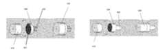
- FIG. 4illustrates an adapter formed by an adapter body and an end section, according to another embodiment.
- FIG. 5illustrates a DC plug end section for attachment to an adapter body, according to an embodiment.
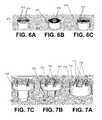
- FIG. 6A through FIG. 6Cillustrate variations to an adapter body, according to some embodiments.
- FIG. 7Aillustrates an adapter body for forming a power adapter combination that utilizes a slide locking mechanism, according to an embodiment.
- FIG. 7Billustrates a type of end section that can be mated with the adapter body of FIG. 7A .
- FIG. 7Cillustrates another kind of end section that can be mated with the adapter body of FIG. 7A .
- FIG. 8A and FIG. 8Billustrate a power adapter combination assembly that utilizes a peg and groove lock connection mechanism for enabling detachable connection of an end section to an adapter body.
- FIG. 9A and FIG. 9Billustrates a variation to an embodiment of FIG. 8A and FIG. 8B .
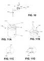
- FIG. 10illustrates another variation in which a power adapter includes a lock and slide connection, under an embodiment.
- FIG. 11Aillustrates a power adapter assembly, according to embodiments.
- FIG. 11Bis a side isometric view of a receptacle interface surface for a power adapter, under an embodiment.
- FIG. 11Cillustrates am end face for a power adapter, under an embodiment.
- FIG. 11Dillustrates use of a second USB or receptacle connector, under another embodiment.
- FIG. 12A through FIG. 12Fillustrates numerous types of prior art adapters for AC outlets.
- FIG. 13illustrates a standard, prior art DC plug adapter, such as used for automobile power outlets.
- a power adapterfor a electrical device.
- the power adaptermay include an adapter body and end section, where the end section can detach and reattach to the adapter body.
- the power adaptermay be used to power or charge electrical devices, such as a mobile electrical device (e.g. wireless telephony/messaging device), portable computers (e.g. netbooks, laptops), portable media player, global positioning system (GPS) device, cameras and/or video recorders.
- a mobile electrical devicee.g. wireless telephony/messaging device
- portable computerse.g. netbooks, laptops
- portable media playere.g. netbooks, laptops
- GPSglobal positioning system
- Embodiments described hereininclude a power adapter for extending power from an electrical power source to a electrical device.
- the power adapterincludes an adapter body, including an exchange surface, having one or more sets of interior electrical contacts.
- the power adapterfurther includes an end section that is attachable and detachable from the body.
- the end sectionincludes (i) a set of end section interior electrical contact elements that make contact with the at least one set of interior electrical contacts, and (ii) a plug connector, electrically connected to the set of end section interior electrical contacts, and adapted to mate with a corresponding electrical receptacle.
- the adapter bodyincludes unified electronics for handing both an incoming alternating current (AC) power signal and a direct current (DC) source.
- ACincoming alternating current
- DCdirect current
- a power adapterfor extending power from an electrical power source to a electrical device.
- the power adapterincludes an adapter body structured to detachably receive any one of a plurality of end sections. Each end section including a plug interface for a particular type of electrical receptacle.
- an embodimentincludes a power adapter that includes a cylindrical adapter body, and an end section including a plug connector.
- FIG. 1illustrates a power adapter, according to embodiments.
- An adapter 100includes an adapter body 110 and an end section 120 (or head). As described by numerous embodiments, a user can detach the end section 120 and swap a different end section of a different type onto the adapter body 110 .
- the adapter body 110 and end section 120each include one or more mechanical attachment structures 122 to enable the end section to mechanically attach and detach from the adapter body 120 .
- the adapter body 110also includes an electrical interface 124 that enables the adapter body to form an electrical connection with different types of end sections, including, for example, DC plugs and non-domestic (e.g. European standard) AC plugs.
- the electrical connection formed between the adapter body 110 and end section 120enables electrical power to extend from a power source (e.g. outlet) to a electrical device that is attached to receive power from the power adapter 100 .
- the end section 120includes an outlet interface (as shown by tongs 128 ) for a particular type of outlet (e.g. wall outlet (domestic or international), car charger etc.).
- the usercan detach end section 120 (e.g. domestic electrical outlet AC plug) from the adapter body 120 and attach a different end section (e.g. DC plug for automobile plug).
- the userattaches one kind of end section 120 onto the adapter body 110 in order to mate and receive power from a wall outlet.
- the usercan replace the wall outlet end section for another end section that can mate with a power port (e.g. “cigarette lighter) of an automobile.
- a power porte.g. “cigarette lighter”
- such embodimentsallow the user to use the same adapter body 110 and cord, rather than having to replace the entire power adapter for different charging environments.
- FIG. 2A and FIG. 2Billustrate end views of the respective mating surfaces of the adapter 110 and the end section 120 , under an embodiment.
- the adapter body 110includes a perimeter wall 212 having an interior exchange surface 214 .
- multiple sets of interior electrical contacts 218 , 219are provided on the exchange surface 214 of the adapter body 110 .
- Each set of electrical contacts 218 , 219are for a particular type of end section 120 .
- Specific examples of types of end sectionsinclude (i) domestic AC wall outlet (e.g. 100-120V/60 Hz; see e.g. FIG. 12A ), (ii) non-domestic AC wall outlet (e.g. 220-240V at 50 Hz; see e.g. FIG. 12B-12E ), and (iii) DC outlet (e.g. 12V automobile adapter; e.g. see FIG. 13 ).
- end section 120includes a perimeter wall 222 and an interior mating surface 224 .
- the interior mating surface 224includes a corresponding set of interior electrical contacts 228 that are aligned to mate with one of the sets of electrical contacts 218 on the exchange surface 214 of the adapter body 210 .
- end section 120attaches to the adapter body 110 through a threaded twist-on and twist-off mechanisms.
- the perimeter wall 212 of the adapter body 110includes thread structures 211 , dimensioned to mate with corresponding thread structures 221 on the perimeter wall 222 of the end section 220 .
- the end section 120 and adapter body 110are able to attach and detach, and form an electrical connection when attached, so as to enable power to be extended from a power source to the adapter body 110 .
- the adapter body 110includes unified electronics to enable treatment of power from various types of sources.
- FIG. 3A and FIG. 3Billustrate an alternative mechanical coupling structure for a power adapter assembly, in accordance with some embodiments.
- FIG. 3A and FIG. 3Bare alternative end views of the respective mating sections of the adapter 110 and the end section 120 .
- a mechanical clasping mechanismserves as the attachment mechanisms for coupling the adapter body 110 and end section 120 .
- exchange surface 214 of the adapter body 110includes the sets of electrical contacts 218 , 219 , as well as one or more clasp members 312 that extend from the exchange surface 214 .
- the interior mating surface 224 of the end section 220includes apertures 322 that are positioned and dimensioned to receive the clasp members 312 .
- the clasp members 312bias and engage the apertures 322 to lock the end section 120 in place. Electrical contacts 228 on the end section 120 are then brought into contact with a corresponding set of electrical contacts 218 on the adapter body 110 . Other end sections 120 may be mated to the adapter body 110 that use the alternative set of electrical contacts 219 on the adapter body 110 . Numerous clasp variations may be implemented, including providing additional or alternative clasps on the end section 120 , to mate with apertures on the adapter body 110 .
- the adapter body 110may include unified electronics for enabling the adapter body to regulate and optionally convert an incoming power supply for the load (i.e. the interconnected electronic device).
- the unified electronicsincludes (i) AC to DC conversion circuits and elements that convert an alternating input of various voltage ranges and frequencies (e.g. domestic and international outlets-e.g. 90-250 v; 50-60 Hz) into a DC signal; (ii) DC regulation circuits, to buck, boost or otherwise regulate incoming DC power signal (e.g. 12-24 volts) and output DC.
- the unified electronicsmay act as an invertor, transforming an incoming DC signal into an AC output.
- FIG.4illustrates an adapter formed by an adapter body and an end section, according to another embodiment.
- the adapter body 410is structured to (detachably) attach to an end section 420 to form an assembled adapter 430 .
- the end section 420includes a receptacle connector 422 (e.g. pair of spaced tongs) for a wall outlet, making the assembled adapter 430 a power adapter for such an outlet.
- the adapter body 410includes unified electronics to enable different types of end sections 420 to be utilized.
- An electric interfacecomprises a concentric ring arrangement of electrical contacts. Each ring 421 is radially positioned to make electrical contact with a corresponding electrical contact of the adapter body 410 .
- the electrical interface of the adapter body 410 and end section 420is provided in multiple sets of blades that are positioned to meet corresponding blades or elements of the end section. Each set of blades may be positioned for a corresponding type of end section.
- adapter body 410connects to an end section 520 that is a plug connector 522 for a DC power source (e.g. car charger).
- the assembled adapter 530becomes a power adapter for such a power source.
- same adapter body 410thus can mate with end sections corresponding to the receptacle plug ( FIG. 4 ) and DC source ( FIG. 5 ).
- FIG. 6A through FIG. 6Cillustrate variations to an adapter body, according to some embodiments.
- An embodiment such as shown in FIG. 6A through FIG. 6Cillustrate an electrical interface on the adapter body 610 that has a ring electrode configuration.
- other electrode configurationsmay be used (e.g. blades, pins or other contact structures and geometries).
- an adapter body 610includes multiple sets of electrodes or contact elements 612 , 614 , with each set being aligned to make contact with corresponding contact elements of a particular type or types of end sections.
- the adapter body 610includes (i) a set of electrodes 612 for an end section that mates with an AC outlet; (ii) a second set of electrodes 614 for an end section that mates with DC receptacle. Each set of electrode 612 , 614 is aligned and positioned to make contact with a corresponding set of electrodes for a particular kind of end section.
- the adapter body 610has unified electronics 615 (represented in phantom), allowing the AC source to range between, for example, 90-250V and 50-60 Hz, and the DC source to range between, for example, 12-24 volts.
- the adapter body 610includes electrodes only for an AC source or outlet.
- the adapter body 610includes electronics for receiving and converting AC inputs of varying voltages and frequencies (e.g. 90-250V, 50-60 Hz), so as to be matable with end sections for different kinds of AC outlets.
- FIG. 6Canother variation is shown in which the adapter body 610 includes electrodes 614 that are positioned to mate with end sections that are DC sources.
- FIG. 7A through FIG. 7Cillustrates a power adapter combination assembly that utilizes a slide locking mechanism, according to one embodiment.
- adapter body 710includes raised structures 712 that extend from an exchange surface 714 .
- the raised structuresinclude a set of contact elements 711 .
- the raised structures 712are dimensioned and shaped to be received by receptacle structures formed on end sections for the adapter body.
- FIG. 7Billustrates a first type of end section 720 that includes receptacle structures 722 for receiving the raised structures. As shown, the end section 720 is a wall outlet plug including the tongs 728 .
- a set of contact elements 721make contact with the set of contact elements on the adapter body 710 .
- the physical mating structure, as provided by the raised structures 712 and the receptacle structures 722thus integrate electrical connectivity between the two end pieces.
- the two pieces depicted in FIG. 7A and FIG. 7Bcan be slide-locked into place (meaning the raised structures 712 slide into the receptacle structures 722 ), using, for example, a friction fit to retain the two pieces in position. When retained, the respective electrical contact elements 711 and 721 form the electrical connection.
- FIG. 7Cillustrates another kind of end section that can be mated with the adapter body of FIG. 7A .
- the end section 730provides a DC plug connector, but has a similar receptacle structure as that shown with the end section of FIG. 7B .
- end section 730includes the DC plug 738 for mating with, for example, a car charger receptacle.
- FIG. 8A and FIG. 8Billustrate a power adapter combination assembly that utilizes a peg and groove lock connection mechanism for enabling detachable connection of an end section to an adapter body.
- adapter body 810includes an exchange surface 814 from which raised, conductive contact elements 816 extend.
- the end section 820includes a platform 824 that receives the exchange surface 814 of the adapter body 810 .
- the platform 824includes openings 824 that expose contact pads or layer 825 .
- the adapter body 810is placed over the end section 820 , so that the perimeter wall 818 of the adapter body is received by a perimeter groove 828 on the end section 820 .
- adapter body 810With the perimeter wall 818 and groove 828 engaged, adapter body 810 is twisted, so that the contact elements 816 of the adapter body 810 engage and lock into the openings 824 the platform 824 , creating electrical connection between pads 825 and the contact elements 816 .
- FIG. 9A and FIG. 9Billustrates a variation to an embodiment of FIG. 8A and FIG. 8B .
- raised contact elements 916extend from exchange surface 914 .
- the contact elements 916are arc shaped.
- the contact elements 916are shaped for polarization.
- the end section 920includes openings 924 that are shaped to receive the contact elements 916 .
- Contact pads 925 or elementsmay underlie the openings 924 , to enable the electrical formation to be created.
- alternative configurationsmay provide for male (protruding) structures to extend from the end sections 820 , 920 to be received by apertures on the adapter bodies 810 , 910 , respectively. Additionally, different types of end sections may be used to mate with an adapter body.
- FIG. 10illustrates another variation in which a power adapter includes a lock and slide connection, under an embodiment.
- one of either the adapter body 1010 or end section 1020include a biased male late member, while the other component includes an aperture for receiving the biased element.
- a male biased latch member 1012extends from the adapter body 1010 to engage the opening 1022 of the end section 1020 .
- an underside of the end section 1021forces the latch member 1022 down into the exchange surface 1014 of the adapter body (see A).
- the userapplies a twist motion (see B) that moves the opening 1022 over the latch member 1012 .
- latch member 1012extends into the opening and releases, causing the latch member to be extended in the opening.
- obstruction 1025 formed in the end section 1020locks the latch member 1012 in place.
- the adapter body 1010 and end section 1020are mechanically locked to form the power assembly.
- An electrical interface between the two componentsmay be implemented as described above.
- the usermay reverse the twist direction while pressing the end section 1020 down, causing the latch member 1012 to bias when it is again aligned in to the opening to have no obstruction. This allows the end section 1020 to be detached from the adapter body 1010 .
- FIG. 11A through FIG. 11Cillustrate a power adapter assembly, under an embodiment.
- a power adapter assembly 1100includes adapter body 1110 and end section 1120 . As described with prior embodiments, the end section 1120 may be detachable from the adapter body 1110 .
- the adapter assembly 1100is cylindrical, and dimensioned so that it can be inserted into an outlet without blocking access to an adjacent outlet. In this regard, embodiments recognize the advantage of using a rounded or circular cross-section to reduce the profile of the power adapter assembly when it is plugged into a wall.
- a receptacle interface surface 1122 of the assembly 1000includes retractable tongs 1121 .
- FIG. 11Bis a side isometric view of the receptacle interface surface 1122 .
- the tongs 1121are shown in both the extended and retracted position. In the retracted position, the tongs 1121 are positioned in the openings or slots 1123 formed into the interface surface 1122 . In the extended position, the tongs 1121 extend substantially orthogonally from the interface surface 1122 . In one embodiment, the tongs 1121 pivot down, and can lie in the slots 1123 to be substantially flush or beneath the interface surface 1122 .
- a cordmay connect to the power adapter assembly in order to enable the power adapter to extend power to a connected device.
- FIG. 11Cillustrates that the adapter body 1110 includes an end face 1132 that provides a connector 1140 for receiving the cord (not shown).
- the connector 1140is a receptacle connector, such as a standard USB connector.
- an alternative connector typemay be used (e.g. Magsafe connector), or the connector may be replace with a cord or wired extension.
- FIG. 11Dillustrates use of a second USB or receptacle connector.
- the first receptacle connector 1140receives a plug connector attached to a cord that extends to a mobile computing device.
- a second receptacle connector 1150can be similarly used to charge, for example, an accessory device of the computing device (e.g. wireless headset), or alternatively a second computing device.
- FIG. 11Dillustrates the use of two USB type connectors, other implementations may use other outlets or connectors.
- one or both connectorsmay correspond to a MagSafe connector, or as an alternative to use of a connector, one or more both connectors may include cords or wired extensions for connection to other computing device.
- the end face 1132includes multiple connectors, or otherwise provides for receiving more than one cord.
- Each received cordmay power or charge a different device.
- each received cordmy power a mobile computing (or other electrical) device and a wireless headset for the device.
Landscapes
- Details Of Connecting Devices For Male And Female Coupling (AREA)
- Connector Housings Or Holding Contact Members (AREA)
Abstract
Description
Claims (17)
Priority Applications (1)
| Application Number | Priority Date | Filing Date | Title |
|---|---|---|---|
| US12/651,402US7993164B2 (en) | 2008-12-31 | 2009-12-31 | Compact power adapter with interchangeable heads |
Applications Claiming Priority (2)
| Application Number | Priority Date | Filing Date | Title |
|---|---|---|---|
| US14217208P | 2008-12-31 | 2008-12-31 | |
| US12/651,402US7993164B2 (en) | 2008-12-31 | 2009-12-31 | Compact power adapter with interchangeable heads |
Publications (2)
| Publication Number | Publication Date |
|---|---|
| US20100190381A1 US20100190381A1 (en) | 2010-07-29 |
| US7993164B2true US7993164B2 (en) | 2011-08-09 |
Family
ID=42354512
Family Applications (1)
| Application Number | Title | Priority Date | Filing Date |
|---|---|---|---|
| US12/651,402Expired - Fee RelatedUS7993164B2 (en) | 2008-12-31 | 2009-12-31 | Compact power adapter with interchangeable heads |
Country Status (1)
| Country | Link |
|---|---|
| US (1) | US7993164B2 (en) |
Cited By (10)
| Publication number | Priority date | Publication date | Assignee | Title |
|---|---|---|---|---|
| US20110305106A1 (en)* | 2010-06-09 | 2011-12-15 | Conocophillips Company | Marine seismic data acquisition using designed non-uniform streamer spacing |
| US20130328526A1 (en)* | 2012-06-07 | 2013-12-12 | Navajo Manufacturing Company, Inc. | Compact car charger |
| CN104170184A (en)* | 2013-03-15 | 2014-11-26 | 佳明瑞士有限责任公司 | Electrical connector for pedal spindle |
| US20170256899A1 (en)* | 2016-03-02 | 2017-09-07 | Vincent Mitchell | System and Method for Providing Marine Shore Power |
| US10809402B2 (en) | 2017-05-16 | 2020-10-20 | Conocophillips Company | Non-uniform optimal survey design principles |
| US11294088B2 (en) | 2014-12-18 | 2022-04-05 | Conocophillips Company | Methods for simultaneous source separation |
| US11481677B2 (en) | 2018-09-30 | 2022-10-25 | Shearwater Geoservices Software Inc. | Machine learning based signal recovery |
| US11543551B2 (en) | 2015-09-28 | 2023-01-03 | Shearwater Geoservices Software Inc. | 3D seismic acquisition |
| US20230134323A1 (en)* | 2021-11-04 | 2023-05-04 | Yu-Yu Chen | Signal detection device for bicycle pedal |
| US12259511B2 (en) | 2017-11-20 | 2025-03-25 | Shearwater Geoservices Software Inc. | Offshore application of non-uniform optimal sampling survey design |
Families Citing this family (7)
| Publication number | Priority date | Publication date | Assignee | Title |
|---|---|---|---|---|
| TWI454027B (en)* | 2011-09-16 | 2014-09-21 | Phihong Technology Co Ltd | Combinative power device |
| JP5578209B2 (en)* | 2012-08-22 | 2014-08-27 | トヨタ自動車株式会社 | Vehicle power control device |
| GB201316969D0 (en)* | 2013-09-26 | 2013-11-06 | Made In Mind Ltd | Power Supply System |
| TWI639283B (en)* | 2017-08-08 | 2018-10-21 | 碩天科技股份有限公司 | Adapter and using method thereof |
| EP3762871B1 (en)* | 2018-03-07 | 2024-08-07 | X-Card Holdings, LLC | Metal card |
| EP4049348A4 (en)* | 2019-10-25 | 2023-08-09 | Techtronic Cordless GP | PORTABLE CHARGER WITH DETECTABLE FEMALE CONNECTORS |
| EP4086870A1 (en)* | 2021-05-07 | 2022-11-09 | Carrier Corporation | Fire protection system |
Citations (14)
| Publication number | Priority date | Publication date | Assignee | Title |
|---|---|---|---|---|
| US4364624A (en)* | 1978-04-14 | 1982-12-21 | Williams Robert A | Adapter assembly for electrical leads |
| US5613863A (en)* | 1995-05-18 | 1997-03-25 | Motorola, Inc. | Power transformer |
| US5744934A (en)* | 1997-05-09 | 1998-04-28 | Formosa Electronic Industries Inc. | Power supply device |
| US5766020A (en)* | 1996-02-12 | 1998-06-16 | Hughes; Michael | Power adapter interface apparatus |
| US5997310A (en)* | 1998-10-21 | 1999-12-07 | Chiu; Pen-Li | Swivel electric plug |
| US6328581B1 (en)* | 2000-08-09 | 2001-12-11 | Chiu-Shan Lee | Universal electric adapter |
| US20020127918A1 (en)* | 2001-03-02 | 2002-09-12 | Terutomo Kajiwara | AC-adapter and pin configuration adapter for AC-adapter |
| US6669495B2 (en)* | 2000-11-06 | 2003-12-30 | Research In Motion Limited | Universal adapter with interchangeable plugs |
| US20040110397A1 (en)* | 2002-12-10 | 2004-06-10 | Delta Electronics, Inc. | Assembly structure of adapter |
| US6923667B1 (en)* | 2004-05-17 | 2005-08-02 | Acbel Polytech Inc. | Rotary adapter |
| US6942508B2 (en)* | 2003-01-03 | 2005-09-13 | Modern Sense Ltd. | Electrical adapter |
| US20080139050A1 (en)* | 2006-12-06 | 2008-06-12 | Sheng-Hsin Liao | Adjustable power plug adapter structure |
| US7632137B1 (en)* | 2008-07-28 | 2009-12-15 | Cheng Uei Precision Industry Co., Ltd. | Power adapter |
| US20090325422A1 (en)* | 2005-11-16 | 2009-12-31 | Bee Chuan James Ooi | Plug Converter for Changing the Electrical Pin Configuration of an Appliance Plug |
Family Cites Families (1)
| Publication number | Priority date | Publication date | Assignee | Title |
|---|---|---|---|---|
| USD525150S1 (en)* | 2004-04-29 | 2006-07-18 | Locman S.P.A. | Watch case |
- 2009
- 2009-12-31USUS12/651,402patent/US7993164B2/ennot_activeExpired - Fee Related
Patent Citations (14)
| Publication number | Priority date | Publication date | Assignee | Title |
|---|---|---|---|---|
| US4364624A (en)* | 1978-04-14 | 1982-12-21 | Williams Robert A | Adapter assembly for electrical leads |
| US5613863A (en)* | 1995-05-18 | 1997-03-25 | Motorola, Inc. | Power transformer |
| US5766020A (en)* | 1996-02-12 | 1998-06-16 | Hughes; Michael | Power adapter interface apparatus |
| US5744934A (en)* | 1997-05-09 | 1998-04-28 | Formosa Electronic Industries Inc. | Power supply device |
| US5997310A (en)* | 1998-10-21 | 1999-12-07 | Chiu; Pen-Li | Swivel electric plug |
| US6328581B1 (en)* | 2000-08-09 | 2001-12-11 | Chiu-Shan Lee | Universal electric adapter |
| US6669495B2 (en)* | 2000-11-06 | 2003-12-30 | Research In Motion Limited | Universal adapter with interchangeable plugs |
| US20020127918A1 (en)* | 2001-03-02 | 2002-09-12 | Terutomo Kajiwara | AC-adapter and pin configuration adapter for AC-adapter |
| US20040110397A1 (en)* | 2002-12-10 | 2004-06-10 | Delta Electronics, Inc. | Assembly structure of adapter |
| US6942508B2 (en)* | 2003-01-03 | 2005-09-13 | Modern Sense Ltd. | Electrical adapter |
| US6923667B1 (en)* | 2004-05-17 | 2005-08-02 | Acbel Polytech Inc. | Rotary adapter |
| US20090325422A1 (en)* | 2005-11-16 | 2009-12-31 | Bee Chuan James Ooi | Plug Converter for Changing the Electrical Pin Configuration of an Appliance Plug |
| US20080139050A1 (en)* | 2006-12-06 | 2008-06-12 | Sheng-Hsin Liao | Adjustable power plug adapter structure |
| US7632137B1 (en)* | 2008-07-28 | 2009-12-15 | Cheng Uei Precision Industry Co., Ltd. | Power adapter |
Non-Patent Citations (1)
| Title |
|---|
| U.S. Appl. No. 29/323,686, filed Aug. 28, 2008, Matsuoka et al. |
Cited By (19)
| Publication number | Priority date | Publication date | Assignee | Title |
|---|---|---|---|---|
| US20110305106A1 (en)* | 2010-06-09 | 2011-12-15 | Conocophillips Company | Marine seismic data acquisition using designed non-uniform streamer spacing |
| US10989826B2 (en) | 2010-06-09 | 2021-04-27 | Conocophillips Company | Seismic data acquisition using designed non-uniform receiver spacing |
| US8897094B2 (en)* | 2010-06-09 | 2014-11-25 | Conocophillips Company | Marine seismic data acquisition using designed non-uniform streamer spacing |
| US10823867B2 (en) | 2010-06-09 | 2020-11-03 | Conocophillips Company | Seismic data acquisition using designed non-uniform receiver spacing |
| US8988040B2 (en)* | 2012-06-07 | 2015-03-24 | Navajo Manufacturing Company, Inc. | Compact car charger |
| US20130328526A1 (en)* | 2012-06-07 | 2013-12-12 | Navajo Manufacturing Company, Inc. | Compact car charger |
| CN104170184A (en)* | 2013-03-15 | 2014-11-26 | 佳明瑞士有限责任公司 | Electrical connector for pedal spindle |
| US11740375B2 (en) | 2014-12-18 | 2023-08-29 | Shearwater Geoservices Software Inc. | Methods for simultaneous source separation |
| US11294088B2 (en) | 2014-12-18 | 2022-04-05 | Conocophillips Company | Methods for simultaneous source separation |
| US11543551B2 (en) | 2015-09-28 | 2023-01-03 | Shearwater Geoservices Software Inc. | 3D seismic acquisition |
| US10153581B2 (en)* | 2016-03-02 | 2018-12-11 | Vincent Mitchell | System and method for connecting to marine shore power |
| US20170256899A1 (en)* | 2016-03-02 | 2017-09-07 | Vincent Mitchell | System and Method for Providing Marine Shore Power |
| US11409014B2 (en) | 2017-05-16 | 2022-08-09 | Shearwater Geoservices Software Inc. | Non-uniform optimal survey design principles |
| US10809402B2 (en) | 2017-05-16 | 2020-10-20 | Conocophillips Company | Non-uniform optimal survey design principles |
| US11835672B2 (en) | 2017-05-16 | 2023-12-05 | Shearwater Geoservices Software Inc. | Non-uniform optimal survey design principles |
| US12259511B2 (en) | 2017-11-20 | 2025-03-25 | Shearwater Geoservices Software Inc. | Offshore application of non-uniform optimal sampling survey design |
| US11481677B2 (en) | 2018-09-30 | 2022-10-25 | Shearwater Geoservices Software Inc. | Machine learning based signal recovery |
| US20230134323A1 (en)* | 2021-11-04 | 2023-05-04 | Yu-Yu Chen | Signal detection device for bicycle pedal |
| US12306051B2 (en)* | 2021-11-04 | 2025-05-20 | Yu-Yu Chen | Bicycle pedal signal detection device |
Also Published As
| Publication number | Publication date |
|---|---|
| US20100190381A1 (en) | 2010-07-29 |
Similar Documents
| Publication | Publication Date | Title |
|---|---|---|
| US7993164B2 (en) | Compact power adapter with interchangeable heads | |
| RU2283521C2 (en) | Multipurpose shaped plug and plug connectors for power supplies | |
| US20190260213A1 (en) | Power adapters for powering and/or charging peripheral devices | |
| US20020055288A1 (en) | Universal adapter with interchangeable plugs | |
| US7985083B2 (en) | Interface between connectable electrical devices | |
| EP1437804A2 (en) | Electrical adapter | |
| US10181680B1 (en) | Securable power adapter | |
| US20230136225A1 (en) | Electronic device with detachable plug | |
| CN106981801A (en) | Adapter assembly | |
| WO2009061018A1 (en) | Multi adapter | |
| US20130267112A1 (en) | Power connector assembly and adapter plug with locking mechanism | |
| TWM583645U (en) | International charger structure | |
| WO1999012244A1 (en) | Combination battery charger and power source with dual-plug assembly for electrically powered devices | |
| JP2020502977A (en) | Adjustable size charger | |
| CN201655923U (en) | Portable electronic device charging module with replaceable plug | |
| TWM575204U (en) | Power connection structure with removable plug | |
| CN223039204U (en) | An all-in-one pluggable multifunctional data cable | |
| US20250141168A1 (en) | Interchangeable plug for a power adapter and methods for providing and using the same | |
| CN220692369U (en) | Conversion base and rotary type change-over plug that charges | |
| CN222691004U (en) | Power connector and power transmission system | |
| CN210779358U (en) | Integrated conversion charger | |
| CN112448422A (en) | Multifunctional charging device | |
| JPH04131887U (en) | power supply | |
| TWM449391U (en) | Extension cord having dedicated connector and independent switch |
Legal Events
| Date | Code | Title | Description |
|---|---|---|---|
| AS | Assignment | Owner name:PALM, INC., CALIFORNIA Free format text:ASSIGNMENT OF ASSIGNORS INTEREST;ASSIGNORS:CHATTERJEE, MANJIRNATH;MATSUOKA, YOSHIMICHI;SKILLMAN, PETER;SIGNING DATES FROM 20100322 TO 20100331;REEL/FRAME:024227/0062 | |
| AS | Assignment | Owner name:HEWLETT-PACKARD DEVELOPMENT COMPANY, L.P., TEXAS Free format text:ASSIGNMENT OF ASSIGNORS INTEREST;ASSIGNOR:PALM, INC.;REEL/FRAME:025204/0809 Effective date:20101027 | |
| STCF | Information on status: patent grant | Free format text:PATENTED CASE | |
| CC | Certificate of correction | ||
| AS | Assignment | Owner name:PALM, INC., CALIFORNIA Free format text:ASSIGNMENT OF ASSIGNORS INTEREST;ASSIGNOR:HEWLETT-PACKARD DEVELOPMENT COMPANY, L.P.;REEL/FRAME:030341/0459 Effective date:20130430 | |
| FEPP | Fee payment procedure | Free format text:PAYER NUMBER DE-ASSIGNED (ORIGINAL EVENT CODE: RMPN); ENTITY STATUS OF PATENT OWNER: LARGE ENTITY Free format text:PAYOR NUMBER ASSIGNED (ORIGINAL EVENT CODE: ASPN); ENTITY STATUS OF PATENT OWNER: LARGE ENTITY | |
| AS | Assignment | Owner name:PALM, INC., CALIFORNIA Free format text:ASSIGNMENT OF ASSIGNORS INTEREST;ASSIGNOR:HEWLETT-PACKARD DEVELOPMENT COMPANY, L.P.;REEL/FRAME:031837/0544 Effective date:20131218 Owner name:HEWLETT-PACKARD DEVELOPMENT COMPANY, L.P., TEXAS Free format text:ASSIGNMENT OF ASSIGNORS INTEREST;ASSIGNOR:PALM, INC.;REEL/FRAME:031837/0659 Effective date:20131218 Owner name:HEWLETT-PACKARD DEVELOPMENT COMPANY, L.P., TEXAS Free format text:ASSIGNMENT OF ASSIGNORS INTEREST;ASSIGNOR:PALM, INC.;REEL/FRAME:031837/0239 Effective date:20131218 | |
| AS | Assignment | Owner name:QUALCOMM INCORPORATED, CALIFORNIA Free format text:ASSIGNMENT OF ASSIGNORS INTEREST;ASSIGNORS:HEWLETT-PACKARD COMPANY;HEWLETT-PACKARD DEVELOPMENT COMPANY, L.P.;PALM, INC.;REEL/FRAME:032132/0001 Effective date:20140123 | |
| FPAY | Fee payment | Year of fee payment:4 | |
| FEPP | Fee payment procedure | Free format text:MAINTENANCE FEE REMINDER MAILED (ORIGINAL EVENT CODE: REM.); ENTITY STATUS OF PATENT OWNER: LARGE ENTITY | |
| LAPS | Lapse for failure to pay maintenance fees | Free format text:PATENT EXPIRED FOR FAILURE TO PAY MAINTENANCE FEES (ORIGINAL EVENT CODE: EXP.); ENTITY STATUS OF PATENT OWNER: LARGE ENTITY | |
| STCH | Information on status: patent discontinuation | Free format text:PATENT EXPIRED DUE TO NONPAYMENT OF MAINTENANCE FEES UNDER 37 CFR 1.362 | |
| FP | Lapsed due to failure to pay maintenance fee | Effective date:20190809 |