US7991363B2 - Tuning matching circuits for transmitter and receiver bands as a function of transmitter metrics - Google Patents
Tuning matching circuits for transmitter and receiver bands as a function of transmitter metricsDownload PDFInfo
- Publication number
- US7991363B2 US7991363B2US11/940,309US94030907AUS7991363B2US 7991363 B2US7991363 B2US 7991363B2US 94030907 AUS94030907 AUS 94030907AUS 7991363 B2US7991363 B2US 7991363B2
- Authority
- US
- United States
- Prior art keywords
- transmitter
- value
- merit
- target
- receiver
- Prior art date
- Legal status (The legal status is an assumption and is not a legal conclusion. Google has not performed a legal analysis and makes no representation as to the accuracy of the status listed.)
- Active, expires
Links
Images


Classifications
- H—ELECTRICITY
- H04—ELECTRIC COMMUNICATION TECHNIQUE
- H04W—WIRELESS COMMUNICATION NETWORKS
- H04W24/00—Supervisory, monitoring or testing arrangements
- H04W24/02—Arrangements for optimising operational condition
- H—ELECTRICITY
- H03—ELECTRONIC CIRCUITRY
- H03H—IMPEDANCE NETWORKS, e.g. RESONANT CIRCUITS; RESONATORS
- H03H7/00—Multiple-port networks comprising only passive electrical elements as network components
- H03H7/38—Impedance-matching networks
- H03H7/40—Automatic matching of load impedance to source impedance
- H—ELECTRICITY
- H04—ELECTRIC COMMUNICATION TECHNIQUE
- H04B—TRANSMISSION
- H04B1/00—Details of transmission systems, not covered by a single one of groups H04B3/00 - H04B13/00; Details of transmission systems not characterised by the medium used for transmission
- H04B1/02—Transmitters
- H04B1/04—Circuits
- H04B1/0458—Arrangements for matching and coupling between power amplifier and antenna or between amplifying stages
Definitions
- the present inventionis directed towards impedance matching circuits and more particularly, adaptive impedance matching circuits to improve transceiver operation in a variety of scenarios.
- Cellular telephone deviceshave migrated from single cellular technology supporting devices to multi-cellular technology devices integrating a variety of other consumer features such as MP3 players, color displays, games, etc. Thus, not only are the cellular telephone devices required to communicate at a variety of frequencies, they are also subjected to a large variety of use conditions. All of these factors can result in a need for different impedance matching circuits for the antenna. However, by utilizing tunable components, a single matching circuit can be used under a variety of circumstances.
- Tunable matching circuitsgenerally operate to adjust the impedance match with an antenna over a frequency range to maximize the output power.
- difficultiesarise when attempting to tune the matching circuit for signal reception.
- an adaptive impedance matching modulethat can operate to optimize performance of both the transmitter and the receiver under a variety of circumstances.
- an adaptive impedance matching modulethat optimizes performance of the transceiver based on optimizing the operation in view of a figure of merit.
- embodiments of the inventioninclude a tunable matching circuit and an algorithm for adjusting the same. More particularly, the tuning circuit is adjusted primarily based on transmitter oriented metrics and is then applied to attain a desired tuning for both transmitter and receiver operation.
- TDMtime division multiplexed
- FDMfrequency division multiplexed
- An exemplary embodiment of the present inventionprovides a method for controlling a matching circuit for interfacing an antenna with a transceiver.
- the matching circuitincludes one or more tunable components.
- the tuning of the matching circuitis based on a figure of merit that incorporates one or more operation metrics.
- One aspect of the present inventionis that the operation metrics can be transmitter based but still provide desired adjustment results for receiver operation.
- the operation metric(s)is monitored and measured and then compared to the figure of merit. If the desired operation is not attained, the variable component(s) of the matching circuit is adjusted using one or more of a variety of techniques to attain the figure of merit. This process is performed to maintain operation at the figure of merit.
- an offset, scaling factor, translation or other change or modificationis applied to the adjustments of the variable components when switching from the transmit mode to the receive mode.
- This translationis a function of the values obtained while adjusting during the transmit time slot. The translation is then removed upon return to the transmitter mode and the adjustment process is resumed.
- the figure of meritnot only incorporates the transmit metrics, but also incorporates an element to attain a compromise between optimal transmitter and optimal receiver operation. This is accomplished by identifying a target operation goal, such as a desired transmitter and receiver reflection loss and then identifying an operational setting that is a close compromise between the two.
- This embodimentthus incorporates not only transmitter metrics but also tuning circuit settings or preferences into the algorithm. The tuning preferences can be empirically identified to ensure the desired operation.
- FIG. 1is a block diagram illustrating an exemplary environment for deployment of one or more embodiments of the present invention.
- FIG. 2is a circuit diagram illustrating further details of an exemplary matching circuit that could be included in the AIMM in an exemplary embodiment of the present invention.
- FIG. 3is a flow diagram illustrating the general steps taken in an exemplary embodiment of the present invention.
- FIG. 4 and FIG. 4Aare a plots of the transmitter reflection losses for four operating frequencies.
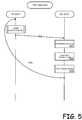
- FIG. 5is a flow diagram illustrating the steps involved in an exemplary embodiment of the present invention operating in a TDM environment.
- FIG. 6is a return loss contour diagram in the PTC plane for a particular frequency (i.e., 825 MHz/870 MHz operation).
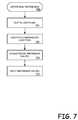
- FIG. 7is a flow diagram illustrating the steps involved in an exemplary embodiment of the present invention in obtaining the preference values for PTC 1 and PTC 2 .
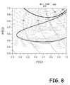
- FIG. 8is a contour plot showing the magnitude and the phase of the reflection coefficient.
- the present inventionis directed towards providing an impedance matching circuit, module or component that in response to sensing the matching condition by monitoring one or more metrics or parameters of the transmitter, can be adjusted to optimize the match.
- embodiments of the present inventioninclude adaptive impedance matching circuits, modules, IC's etc., that operate to sense the matching condition of the transmit signal or other transmitter related metric and then optimizes the matching characteristics by adjusting the values of one or more tunable devices in view of attaining or reaching a figure of merit.
- the figure of meritcan be based on a variety of elements, such as the input return loss, output power, current drain, linearity metrics, as well as others. In the embodiments of the present invention that are presented herein, the figure of merit is typically described or defined as being based on the input return loss.
- an adaptive impedance matching moduledetects transmitter related metrics and optimizes the matching circuit keyed on the transmit signal.
- a benefit associated with focusing on the transmit signal, as well as other transmitter metrics,is that the transmit signal is higher in power than the receive signal and thus, is easier to detect.
- the present inventionoperates to optimize a figure of merit that achieves a desired operation of both signals even though the matching adjustments performed by the AIMM are only based on sensing the transmitter related metrics.
- One embodiment of the inventionis particularly well suited for operating in a time division multiplexed (TDM) system.
- TDMtime division multiplexed
- the radiotransmits and receives in different time slots.
- the transmitter and receiveralso operate on different frequencies; however, it will be appreciated that some systems utilize the same frequency for transmission and reception. Nonetheless, in a TDM system, the transmitter and receiver are not active at the same time.
- the AIMMcan be adjusted to optimal settings for the transmitter during a transmit time slot and then the AIMM can be adjusted to optimal setting for the receiver during the receive time slot.
- the AIMM tunercan be set differently during transmit and receive time slots.
- an adjustment algorithmis applied to determine the appropriate settings of the AIMM to optimize the match or attain a figure of merit that results in achieving or approaching a desired level of operation. Because any frequency offset between the transmit signal and the receive signal is known, an adjustment or modification of the setting of the AIMM in the form of a translation or some other function is applied to the AIMM during the receive time slot. The adjustment improves the matching characteristics at the receiver frequency based on knowledge determined during the transmit time slot and the general operation of the receiver. During the next transmit time slot, the translation is removed from the AIMM and the adjustment algorithm regains control of the AIMM. Upon returning to the receive time slot, the modification can be reapplied or, if the settings during the transmit time slot have been changed, then the new settings can be modified for the subsequent receive time slot.
- the adjustment applied to the AIMM during the receive time slotcan be obtained in a variety of manners.
- the adjustmentmay be a translation derived empirically by characterizing the tuner at the transmitter and receiver frequencies and then deriving a mapping function to describe the translation.
- the translationmay be derived by using the known (or theoretical) S-parameters of the tuner network.
- Another embodiment of the present inventionis particularly suited for a Frequency Division Multiplexed (FDM) system.
- FDMFrequency Division Multiplexed
- the radiotransmits and receives at the same time but at different frequencies.
- the FDM applicationrequires the AIMM to use the same tuning condition for both transmitter and receiver operation.
- the tuneris adjusted to provide a desired compromise between matching at the transmit frequency and matching at the receive frequency. It will be appreciated that this compromise could be attained by simply defining a figure of merit that incorporates both a transmitter metric and a receiver metric.
- the receive signalis typically lower than the transmit signal and as such, it may be difficult to accurately sense and use as a metric.
- non-receiver related metricsare used to find a desired compromised state for tuning the AIMM.
- the desired compromised statecan vary based on embodiment and operational requirements.
- transmission of datamay be more important than reception and as such, preference may be given to optimizing the transmitter.
- the reception of datamay be more important than the transmission.
- the reception of weather related informationas an emergency warning system.
- preferencemay be given to optimizing the receiver.
- both the reception and transmission of datamay be equally important and as such, a setting that gives a compromised performance or attempts to equalize the performance of both the transmitter and receiver is desired. Such an embodiment is typical of cellular telephone operation.
- the FDM suitable embodiments of the present inventionoperate to obtain a desired level of operation based on one or more transmitter related metrics, and also incorporate known characteristics about the tuning circuits to achieve the desired operating state.
- the desired operating statetypically reflects a state of operation that is a compromise from the optimal states for the transmitter and receiver.
- one embodiment of the present inventionmay include the tuning states of the tunable devices in the matching circuit within a transmit signal based figure of merit.
- this aspect of the present inventionenables improved performance in the receive band without having to take a receiver measurement.
- Another embodiment of the invention deployable within an FDM environmentis to tune the matching circuit to a figure of merit that is based on a vector measurement of the transmitter reflection coefficient.
- the phase information in the vector measurementis incorporated into the figure of merit and the optimal compromise between the transmitter and receiver operation occurs at a particular phase of the transmitter reflection coefficient.
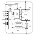
- FIG. 1is a block diagram illustrating an exemplary environment for deployment of one or more embodiments of the present invention.
- the illustrated embodimentincludes an adaptive impedance matching module (AIMM) 100 , however, it should be appreciated that the invention can be incorporated into embodiments that utilize discrete components, integrated circuits, a combination of software, firmware and hardware, or the like, and that the embodiment presented as a module is a non-limiting example. Further, although the present invention is described within the context of an AIMM, it will be appreciated that various aspects, features and embodiments equally apply to other configurations.
- the AIMM 100includes a tuner 110 that includes a matching circuit with one or more tunable elements or components.
- An exemplary embodiment of a tunerincludes tunable capacitances and more specifically, two tunable capacitances, but it will be appreciated that the present invention can be applied to a wide variety of tunable impedance matching circuits.
- the environmentmay further include a high-voltage ASIC (HV-ASIC) 130 containing a DC/DC converter and at least two DACs to generate the high voltage bias signals 132 and 134 required to control the tunable components.
- a micro-controller, microprocessor or other processing unit (PU) 140receives output signals from the forward detector 120 and the reflected detector 125 and can calculate the reflected loss of the transmitted signal and thus, characterize the impedance matching of the circuit.
- the PU 140also interfaces or includes one or more memory elements including, but not limited to various forms of volatile and non-volatile memory. For instance, the PU may periodically write values to memory and read values from memory, such as settings for the variable components in the AIMM.
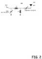
- FIG. 2is a circuit diagram illustrating further details of an exemplary matching circuit 200 that could be included in the AIMM 100 for an exemplary embodiment of the present invention.
- the illustrated matching circuit 200includes a first tunable capacitance PTC 1 , a first impedance L 1 , a second impedance L 2 and a second tunable capacitance PTC 2 where PTC is a Paratek Tunable Capacitor.
- the first tunable capacitance PTC 1is coupled to ground on one end and to the output of a transceiver on the other end.
- the node of PTC 1 that is coupled to the transceiveris also connected to a first end of the first impedance L 1 .
- the second impedance L 2is connected between the second end of the first impedance L 1 and ground.
- the second end of the first impedance L 1is also coupled to a first end of the second tunable capacitance PTC 2 .
- the second end of the second tunable capacitance PTC 2is then coupled to an antenna 210 .
- the tunable capacitancescan be tuned over a range such as 0.3 to 1 times a nominal value C. For instance, if the nominal value of the tunable capacitance is 5 pF, the tunable range would be from 1.5 to 5 pF.
- PTC 1has a nominal capacitance of 5 pf and is tunable over the 0.3 to 1 times range
- the first impedance L 1as a value of 3.1 nH
- the second impedance L 2has a value of 2.4 nH
- the second tunable capacitance PTC 2has a nominal value of 20 pF and can be tuned over a range of 0.3 to 1 times the nominal value.
- the tunable capacitances in the illustrated embodimentcould be tuned oar adjusted over their ranges in an effort to optimize the matching characteristics of the AIMM under various operating conditions.
- the tunable capacitancescan be adjusted to optimize performance or attain a desired level of performance.
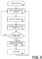
- FIG. 3is a flow diagram illustrating the general steps taken in an exemplary embodiment of the present invention.
- the basic flow of the algorithm 300initially includes measuring the performance parameters or metrics 310 used as feedback pertaining to the performance of the AIMM or the impedance match between a transceiver and an antenna.
- the performance metrics utilizedmay vary over embodiments of the present invention, over various usage scenarios, over technology being utilized (i.e. FDM, TDM, etc.), based on system settings and/or carrier requirements, etc.
- the performance metricsinclude one or more of the following transmitter related metrics: the transmitter return loss, output power, current drain, and transmitter linearity.
- a current figure of meritis calculated 320 .
- the current FOMis based on the one or more performanc metrics, as well as other criteria.
- the current FOMis then compared to a target FOM 325 .
- the target FOMis the optimal or desired performance requirements or objective for the system.
- the target FOMcan be defined by a weighted combination of any measurable or predictable metrics. For instance, if it is desired to maximize the efficiency of the transmitter, the target FOM can be defined to result in tuning the matching network accordingly. Thus, depending on the goal or objective, the target FOM can be defined to tune the matching network to achieve particular goals or objectives.
- the objectivesmay focus on total radiated power (TRP), total isotropic sensitivity (TIS), efficiency and linearity.
- TRPtotal radiated power
- TIStotal isotropic sensitivity
- the target FOMmay be significantly different for a TDM system and an FDM system. It should be understood that the target FOM may be calculated or selected on the fly based on various operating conditions, prior measurements, and modes of operation or, the target FOM could be determined at design time and hard-coded into the AIMM 100 .
- new tuning values for the AIMM 100are calculated or selected 335 . However, if the current FOM is equal to or within the defined threshold, then processing continues by once again measuring the performance metrics 310 and repeating the process. Finally, if the current FOM needs to be adjusted towards the target FOM, the AIMM 100 is adjusted with the new tuning values in an effort to attain or achieve operation at the target FOM 340 . In some embodiments, this new tuning value may also be stored as a new default tuning value of the transmitter at the given state of operation.
- a single default valuecan be used for all situations, and as such, the latest tuning values could be stored in the variable location.
- a default tuning statemay be maintained for a variety of operational states, such as band of operation, use case scenario (i.e., hand held, antenna up/down, slider in/out, etc.) and depending on the current operational state, the new tuning values may be stored into the appropriate default variable.
- the AIMM 100is adjusted by tuning one or more of the tunable components 340 , measuring the new FOM (i.e., based on the transmitter reflected loss) 320 - 330 , and re-adjusting or retuning the AIMM 100 accordingly 335 - 340 in a continuous loop.
- This processis referred to as walking the matching circuit because is moves the circuit from a non-matched state towards a matched state one step at a time.
- This processis continued or repeated to attain and/or maintain performance at the target FOM.
- the process identified by steps 310 to 340can be repeated periodically, a periodically, as needed, or otherwise.
- the loopingis beneficial because even if performance at the target FOM is attained, adjustments may be necessary as the mode of operation (such as usage conditions) of the device change and/or the performance of the transmitter, the antenna and the matching circuitry change over time.
- the tunable componentscan be set based on look-up tables or a combination of look-up tables and performing fine-tuning adjustments.
- the step of calculating the AIMM tuning values 335may involve accessing initial values from a look-up table and then, on subsequent loops through the process, fine tuning the values of the components in the AIMM 100 .
- the AIMM 100can be adjusted to optimize the operation of the transmitter during the transmit time slot.
- the performance metricmay simply be the transmitter return loss.
- the target FOM in such an embodimentmay also simply be a function of the transmitter return loss.
- the AIMM 100can be tuned to minimize the FOM or the transmitter return loss.
- this embodiment of the present inventioncan operate to tune the values of PTC 1 and PTC 2 to minimize the transmitter return loss during the transmit time slot.
- the algorithm of FIG. 3includes measuring the transmitter return loss, calculating adjustment values for PTC 1 and PTC 2 to optimize a FOM that is a function of the transmitter return loss, tuning the AIMM 100 by adjusting the values of PTC 1 and PTC 2 and then repeating the process.
- the adjustment values for PTC 1 and PTC 2can be determined in a variety of manners. For instance, in one embodiment of the invention the values may be stored in memory for various transmitter frequencies and usage scenarios. In other embodiments, the values may be heuristically determined on the fly by making adjustments to the tuning circuit, observing the effect on the transmitter return loss, and compensating accordingly. In yet another embodiment, a combination of a look-up table combined with heuristically determined fine tuning can be used to adjust the AIMM 100 .
- the AIMM 100can be readjusted to optimize or improve the performance of the receiver.
- particular performance parametersmay be measured and used to calculate a current FOM, as previously mentioned it is difficult to measure such performance parameters for the receiver.
- an exemplary embodiment of the present inventionoperates to apply a translation to the tuning values of the AIMM 100 derived at during the transmitter time slot, to improve the performance during the receive time slot.
- the characteristics of performance between the transmitter operation and receiver operationcan be characterized. This characterization can then be used to identify an appropriate translation to be applied.
- the translationmay be selected as a single value that is applicable for all operational states and use cases or, individual values can be determined for various operational states and use cases.
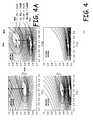
- FIG. 4is a plot of the transmitter reflection losses for four operating frequencies of a transceiver.
- the contoursshow the increasing magnitude of the reflection loss in 1 dB increments.
- the inside contour for the transmitter 406is 20 dB and the bolded contour is 404 14 dB.
- operation at the center of the contours 402is optimal during transmitter operation.
- the translationvaries depending on a variety of circumstances and modes of operation including the frequency of operation, and similarly, may vary based on usage of the device housing the circuitry.
- the performanceis determined to be greatly improved for the receiver time slot if the value of PTC 2 for receiver operation is adjusted to be 0.6 times the value of PTC 2 used for the optimal transmitter setting and the value of PTC 1 remains the same. This is true for each of the illustrated cases except at the 915 MHz/960 MHz operational state.
- 960 MHzit is apparent that significant receiver improvement can be realized by also adjusting the value of PTC 1 from its transmitter value.
- PTC 1 — RxPTC 1 — Tx+ 1 ⁇ 1.8 *PTC 2 — Tx.
- this equationis only a non-limiting example of an equation that could be used for a particular circuit under particular operating conditions and the present invention is not limited to utilization of this particular equation.
- FIG. 5is a flow diagram illustrating the steps involved in an exemplary embodiment of the present invention operating in a TDM environment.
- the AIMM algorithm presented in FIG. 3or some other suitable algorithm, can be applied on a continual basis to move operation of the transmitter towards the target FOM.
- the receive time slotis activated 505
- the AIMMshould be adjusted to match for the receiver frequency.
- the adjustment to the receiver mode of operationmay initially involve determining the current operating conditions of the device 510 .
- a translation for tuning of the various circuits in the AIMM 100are identified 520 . For instance, various states, components or conditions can be sensed and analyzed to determine or detect a current state or a current use case for the device.
- a particular translation value or functionmay be retrieved and applied. It should also be appreciated that such translations can be determined during the design phase and loaded into the device. Finally, the translations are applied to the AIMM 100 530 . When operation returns to the transmitter time slot 535 , the AIMM algorithm again takes over to optimize operation based on the target FOM.
- the translation applied to tuning of the AIMM 100 during the receiver time slotis based on the particular circuit and device and can be determined during design or even on an individual basis during manufacturing and testing. As such, the specific translations identified herein are for illustrative purposes only and should not be construed to limit the operation of the present invention.
- embodiments of the present inventionoperate to optimize operation of a device by tuning the matching circuit for an antenna to optimize operation based on a target FOM.
- a translationis applied to the tuned components to improve receiver performance.
- the target FOMcan be based on a variety of performance metrics and a typical such metric is the reflection loss of the transmitter.
- the values for the tuned componentscan be set based on operational conditions and using a look-up table, can be initially set by using such a look-up table and then heuristically fine tuned, or may be heuristically determined on the fly during operation.
- the translations applied during the receiver operationare determined empirically based on the design of the circuitry and/or testing and measurements of the operation of the circuit.
- a unique aspect of the present inventionis tuning of the matching circuit during transmit mode and based on non-receiver related metrics and then retuning the circuit during receive mode operation based on a translation to optimize or attain a desired level of receiver operation.
- the AIMM 100can be adjusted to so that the matching characteristics represent a compromise between optimal transmitter and receiver operation.
- the translation applied in the TDM examplecould be modified to adjust the AIMM 100 as a compromise between the optimal transmit and receive settings.
- the value of PTC 1 and PTC 2can be determined and adjusted periodically, similar to TDM operation (even though such action would temporarily have an adverse effect on the receiver).
- a translationcould be applied to the values of PTC 1 and PTC 2 for the majority of the operation time. For instance, in the TDM example shown in FIG.
- the transmitter valueswere adjusted by multiplying the PTC 2 value by 0.6 in three modes of operation and using the above-identified equation during a forth mode of operation.
- This same schemecould be used in the FDM mode of operation however, the scaling factor would be different to obtain operation that is compromised between the optimal transmitter setting and optimal receiver setting. For example, multiplying the PTC 2 value by 0.8 could attain an acceptable compromise.
- another technique of an embodiment of the present inventionis to apply an algorithm that operates to attain a target FOM that is based on one or more transmitter related metrics (such as return loss) and the values of the adjustable components in the AIMM.
- this aspect of the present inventioncontinuously attempts to maintain a compromised state of operation that keeps the operation of the transmitter and the receiver at a particular target FOM that represents a compromise performance metric level.
- such an algorithmcould be based on a target FOM that is an expression consisting of the transmitter return loss and the values of PTC 1 and PTC 2 .
- a compromised valueis specified.
- a specific target transmitter return losscan be pursued for both transmitter and receiver operation by tuning the AIMM based on a FOM that is not only a function of the return loss, but also a function of the values of PTC 1 and PTC 2 that will encourage operation at a specific level.
- the target FOMis attained when the actual transmitter return loss is equal to the target transmitter return loss and, specified preferences for PTC 1 and PTC 2 are satisfied.
- the preferences illustratedare for the value of PTC 1 to be the highest possible value and the value of PTC 2 to be the lowest possible value while maintaining the transmit return loss at the target value and satisfying the PTC 1 and PTC 2 preferences.
- FIG. 6is a return loss contour diagram in the PTC plane for a particular frequency (i.e., 825 MHz/870 MHz operation).
- a compromiseis typically selected. For instance, a compromise may include operating the transmitter at a target return loss value of ⁇ 12 dB and at a point at which the transmitter ⁇ 12 dB contour is closest to a desired receiver contour (i.e., ⁇ 12 dB).
- the operational goal of the systemis to attempt to maintain the matching circuit at a point where the operational metrics for the transmitter are at a target value (eg. ⁇ 12 dB) and the estimated desired receiver operation is most proximate.
- a target valueeg. ⁇ 12 dB
- exemplary embodiments of the present inventionoptimize the transmitter based on the target reflected loss to attain operation on the desired contour 610 (as shown in FIG. 6 ) and also adjusts the values of PTC 1 and PTC 2 to attain operation at the desired location 630 (or minimum FOM) on the contour.
- the portion of the FOM equation including the TxRL and TX_RL_Target valuesensures operation on the targeted RL contour 610 (i.e., the ⁇ 12 db RL contour).
- the values of PTC 1 and PTC 2can be incorporated into the target FOM equation to force or encourage operation at a particular location on the reflected loss contour.
- the target FOMis the point at which the reflected loss contour is closest to the expected same valued reflected loss contour for the receiver.
- the target FOMmay be selected to encourage operation at a mid-point between optimal transmitter performance and expected optimal receiver performance.
- the target FOMmay be selected to encourage operation at a point that is mid-point between a desired transmitter metric and an estimated or measured equivalent for the receiver metric.
- the optimum, compromised or desired point on the target contouris the point that minimizes the value of PTC 2 and maximizes the value of PTC 1 in accordance with the equation C 2 *PTC 2 ⁇ C 1 *PTC 1 .
- the portion of the expression including PTC 1 and PTC 2ensures that operation is at a particular location on the contour that is desired—namely on the lower portion of the contour and closest to the RX_RL contour 620 .
- the algorithmoperates to optimize the current FOM or, more particularly in the illustrated embodiment, to minimize the expression of C 2 *PTC 2 —C 1 *PTC 1 as long as the desired TX_RL parameter is also met. It should be appreciated that the details associated with this example are associated with a specific circuit design and a wide variety of relationships between the adjustable components of the AIMM would apply on a circuit by circuit basis and as such, the present invention is not limited to this specific example.
- Another embodiment of the present inventionmay take into consideration historical performance of the tunable components as well as current values. As an example, as the tunable components are adjusted, changes in the current FOM will occur in a particular direction (i.e., better or worse). As an example, if the AIMM adjustments 26 result in the current FOM falling on the top portion of a desired performance contour, making a particular adjustment may result in making the current FOM worse or better. If the adjustment was known to cause a certain result when the current FOM is located on the bottom of the contour and this time, the opposite result occurs, then this knowledge can help identify where the current FOM is located on the contour. Thus, knowing this information can be used in combination with the operation metric to attain the operation at the target FOM. For instance, the target FOM may be a function of the operational metrics, the current states of the tunable components, and the knowledge of previous results from adjusting the tunable components.
- the adjustments to reach the target FOMmay take into consideration past reactions to previous adjustments.
- the adjustment to the tunable componentsmay be a function of the FOM associated with a current setting and, the change in the current FOM resulting from previous changes to the tunable components.
- the FOMmay be optimized similar to operation in the TDM environment.
- the FOMmay be a function of the transmitter reflected loss metric and the system may function to optimize the FOM based on this metric.
- the tunable componentscan be adjusted based on a predetermined translation to move the FOM from the optimized for the transmitter position to a position that is somewhere between the optimal transmitter setting and the optimal receiver setting.
- FIG. 7is a flow diagram illustrating the steps involved in an exemplary embodiment of the present invention in obtaining the preference values for PTC 1 and PTC 2 .
- the process 700involves plotting of the return loss contours for the various modes of operation, or a reasonable subset thereof 710 .
- FIG. 6is an example of such a plot generated as a result of performing this step.
- the compromised tuning locationis identified 720 .
- a variety of factorsmay be weighed to determine the compromised tuning location and one example, as illustrated in FIG. 6 , is the point at which a target reflected loss for the transmitter is the most proximate to a target reflected loss for the receiver.
- thisis the point at which the target transmitter and receiver contours at the desired reflected loss are closest to each other and nearly parallel.
- the preference valuescan be characterized 730 . For instance, in the example in FIG. 6 , by drawing a perpendicular line between the two contours and passing through the compromised location, the slope and hence the preferences can be identified. These preference values can then be determined and then applied across the broad spectrum of frequencies and usage scenarios 740 .
- C 1 and C 2are constants and can vary among embodiments of the invention, as well as among devices employing the invention. As such, the values are determined empirically as described above. In an exemplary embodiment, the values of C 1 and C 2 are 0.7 and 2 respectively for a given circuit and a given antenna, given mode of operation, etc. Thus, any given set of constants are determined empirically and only apply to a specific antenna design, circuit and mode of operation and, although the use of these specific values may in and of itself be considered novel, the present invention is not limited to the particular expression. In fact, depending on particular goals, design criteria, operational requirements, etc. different values may be required to attain the compromised performance. It will also be appreciated that in various embodiments, it may be desired to have a different targeted reflection loss for the transmitter than for the receiver.
- the reflection coefficient vectormay be measured.
- the phase information of the reflection coefficientmay be included within the FOM.
- FIG. 8is a contour plot showing the magnitude and the phase of the reflection coefficient.
- the preferred point of operation 830is shown as falling on the ⁇ 12 dB contour 810 and at a phase of 45 degrees.
- the components of the matching circuit of the AIMM 100can be adjusted to meet a reflected loss value that falls on the ⁇ 12 db contour and that also approaches the specific point on the contour—namely at the point where the reflection coefficient differs by 45 degrees.
- a typical cellular telephonecould be operated in various scenarios including speaker phone mode, ear budded, with the antenna in the up position or the down position, in the user's hand, holster, pocket, with a slider closed or extended, in a holster or out of a holster, etc. All of these scenarios, as well as a variety of other environmental circumstances can drastically alter the matching characteristics of the cellular telephone's antenna circuitry. As such, not only do the various embodiments of the present invention operate to tune the matching circuitry based on the operational frequency, but in addition, adjust the matching characteristics based on changes in the modes of operation.
- various other parameterscan be monitored to identify various use cases and then adjustments to the tuning circuitry can be immediately deployed followed by fine tuning adjustments to optimize the FOM.
- the other parameters in which the embodiments of the present invention may functionare referred to as modes of operation.
- the various modes of operationinclude the use cases as previously described, along with operating environments, bands of operation, channel frequencies, modulation formats and schemes, and physical environments.
- the various embodiments of the present inventionmay make changes, select default values, calculate adjustment values, etc., all as a function of one or more of the modes of operation.
- each use casemay include a default value.
- the default valueis obtained from memory and the components in the AIMM are tuned accordingly. From that point on, the adjustment algorithm can then commence fine tuning of the operation.
- the new valuesmay be written into the default location as the new default values.
- variable tuner networkcould be used to create a variable tuner network.
- variable inductorsor other tunable networks, built out of elements such as Micro-Electro-Mechanical Systems (MEMS) and/or other tunable variable impedance networks could be used in such an AIMM system.
- MEMSMicro-Electro-Mechanical Systems
- Embodiments of the present inventionmay include apparatuses for performing the operations herein.
- An apparatusmay be specially constructed for the desired purposes, or it may comprise a general purpose computing device selectively activated or reconfigured by a program stored in the device.
- a programmay be stored on a storage medium, such as, but not limited to, any type of disk including floppy disks, optical disks, compact disc read only memories (CD-ROMs), magnetic-optical disks, read-only memories (ROMs), random access memories (RAMs), electrically programmable read-only memories (EPROMs), electrically erasable and programmable read only memories (EEPROMs), magnetic or optical cards, or any other type of media suitable for storing electronic instructions, and capable of being coupled to a system bus for a computing device.
- a storage mediumsuch as, but not limited to, any type of disk including floppy disks, optical disks, compact disc read only memories (CD-ROMs), magnetic-optical disks, read-only memories (ROMs), random access memories (
- Coupledmay be used to indicate that two or more elements are in direct physical or electrical contact with each other.
- Connectedmay be used to indicate that two or more elements are in direct physical or electrical contact with each other.
- Connectedmay be used to indicate that two or more elements are in either direct or indirect (with other intervening elements between them) physical or electrical contact with each other, and/or that the two or more elements co-operate or interact with each other (e.g. as in a cause an effect relationship).
- each of the verbs, “comprise,” “include,” and “have”, and conjugates thereof,are used to indicate that the object or objects of the verb are not necessarily a complete listing of members, components, elements, or parts of the subject or subjects of the verb.
Landscapes
- Engineering & Computer Science (AREA)
- Computer Networks & Wireless Communication (AREA)
- Signal Processing (AREA)
- Input Circuits Of Receivers And Coupling Of Receivers And Audio Equipment (AREA)
- Transceivers (AREA)
- Transmitters (AREA)
Abstract
Description
PTC1—Rx=PTC1—Tx+1−1.8*PTC2—Tx.
TargetFOM=f(Tx—RL, TX—RL_Target)+f(PTC2,PTC1)
- Where:
- TX_RL is the measure transmitter return loss
- TX_RL_Target is the targeted transmitter return loss
- Where:
FOM=(Tx—RL−Tx—RL_Target)+C2*PTC2−C1*PTC1), where,
- C1 and C2 are preference constants or scaled values, and
ifTx—RL>Tx—RL_Target thenTx—RL=Tx—RL_Target.
- C1 and C2 are preference constants or scaled values, and
Claims (23)
Priority Applications (6)
| Application Number | Priority Date | Filing Date | Title |
|---|---|---|---|
| US11/940,309US7991363B2 (en) | 2007-11-14 | 2007-11-14 | Tuning matching circuits for transmitter and receiver bands as a function of transmitter metrics |
| PCT/US2008/083529WO2009064968A1 (en) | 2007-11-14 | 2008-11-14 | Tuning matching circuits for transmitter and receiver bands as a function of transmitter metrics |
| US13/168,529US8428523B2 (en) | 2007-11-14 | 2011-06-24 | Tuning matching circuits for transmitter and receiver bands as a function of transmitter metrics |
| US13/693,388US8798555B2 (en) | 2007-11-14 | 2012-12-04 | Tuning matching circuits for transmitter and receiver bands as a function of the transmitter metrics |
| US14/716,014USRE47412E1 (en) | 2007-11-14 | 2015-05-19 | Tuning matching circuits for transmitter and receiver bands as a function of the transmitter metrics |
| US16/372,838USRE48435E1 (en) | 2007-11-14 | 2019-04-02 | Tuning matching circuits for transmitter and receiver bands as a function of the transmitter metrics |
Applications Claiming Priority (1)
| Application Number | Priority Date | Filing Date | Title |
|---|---|---|---|
| US11/940,309US7991363B2 (en) | 2007-11-14 | 2007-11-14 | Tuning matching circuits for transmitter and receiver bands as a function of transmitter metrics |
Related Parent Applications (3)
| Application Number | Title | Priority Date | Filing Date |
|---|---|---|---|
| US13/168,529ContinuationUS8428523B2 (en) | 2007-11-14 | 2011-06-24 | Tuning matching circuits for transmitter and receiver bands as a function of transmitter metrics |
| US13/693,388ReissueUS8798555B2 (en) | 2007-11-14 | 2012-12-04 | Tuning matching circuits for transmitter and receiver bands as a function of the transmitter metrics |
| US16/372,838ReissueUSRE48435E1 (en) | 2007-11-14 | 2019-04-02 | Tuning matching circuits for transmitter and receiver bands as a function of the transmitter metrics |
Related Child Applications (1)
| Application Number | Title | Priority Date | Filing Date |
|---|---|---|---|
| US13/168,529ContinuationUS8428523B2 (en) | 2007-11-14 | 2011-06-24 | Tuning matching circuits for transmitter and receiver bands as a function of transmitter metrics |
Publications (2)
| Publication Number | Publication Date |
|---|---|
| US20090121963A1 US20090121963A1 (en) | 2009-05-14 |
| US7991363B2true US7991363B2 (en) | 2011-08-02 |
Family
ID=40623230
Family Applications (5)
| Application Number | Title | Priority Date | Filing Date |
|---|---|---|---|
| US11/940,309Active2029-10-02US7991363B2 (en) | 2007-11-14 | 2007-11-14 | Tuning matching circuits for transmitter and receiver bands as a function of transmitter metrics |
| US13/168,529Active2027-12-01US8428523B2 (en) | 2007-11-14 | 2011-06-24 | Tuning matching circuits for transmitter and receiver bands as a function of transmitter metrics |
| US13/693,388CeasedUS8798555B2 (en) | 2007-11-14 | 2012-12-04 | Tuning matching circuits for transmitter and receiver bands as a function of the transmitter metrics |
| US14/716,014ActiveUSRE47412E1 (en) | 2007-11-14 | 2015-05-19 | Tuning matching circuits for transmitter and receiver bands as a function of the transmitter metrics |
| US16/372,838Expired - Fee RelatedUSRE48435E1 (en) | 2007-11-14 | 2019-04-02 | Tuning matching circuits for transmitter and receiver bands as a function of the transmitter metrics |
Family Applications After (4)
| Application Number | Title | Priority Date | Filing Date |
|---|---|---|---|
| US13/168,529Active2027-12-01US8428523B2 (en) | 2007-11-14 | 2011-06-24 | Tuning matching circuits for transmitter and receiver bands as a function of transmitter metrics |
| US13/693,388CeasedUS8798555B2 (en) | 2007-11-14 | 2012-12-04 | Tuning matching circuits for transmitter and receiver bands as a function of the transmitter metrics |
| US14/716,014ActiveUSRE47412E1 (en) | 2007-11-14 | 2015-05-19 | Tuning matching circuits for transmitter and receiver bands as a function of the transmitter metrics |
| US16/372,838Expired - Fee RelatedUSRE48435E1 (en) | 2007-11-14 | 2019-04-02 | Tuning matching circuits for transmitter and receiver bands as a function of the transmitter metrics |
Country Status (2)
| Country | Link |
|---|---|
| US (5) | US7991363B2 (en) |
| WO (1) | WO2009064968A1 (en) |
Cited By (36)
| Publication number | Priority date | Publication date | Assignee | Title |
|---|---|---|---|---|
| US20120264380A1 (en)* | 2011-03-14 | 2012-10-18 | Nujira Limited | Polar Amplification Transmitter Distortion Reduction |
| US8395459B2 (en) | 2008-09-24 | 2013-03-12 | Research In Motion Rf, Inc. | Methods for tuning an adaptive impedance matching network with a look-up table |
| US8432234B2 (en) | 2010-11-08 | 2013-04-30 | Research In Motion Rf, Inc. | Method and apparatus for tuning antennas in a communication device |
| US8457569B2 (en) | 2007-05-07 | 2013-06-04 | Research In Motion Rf, Inc. | Hybrid techniques for antenna retuning utilizing transmit and receive power information |
| US8463218B2 (en) | 2006-01-14 | 2013-06-11 | Research In Motion Rf, Inc. | Adaptive matching network |
| US8472888B2 (en) | 2009-08-25 | 2013-06-25 | Research In Motion Rf, Inc. | Method and apparatus for calibrating a communication device |
| US8558633B2 (en) | 2006-11-08 | 2013-10-15 | Blackberry Limited | Method and apparatus for adaptive impedance matching |
| US8594584B2 (en) | 2011-05-16 | 2013-11-26 | Blackberry Limited | Method and apparatus for tuning a communication device |
| US8620236B2 (en) | 2007-04-23 | 2013-12-31 | Blackberry Limited | Techniques for improved adaptive impedance matching |
| US8626083B2 (en) | 2011-05-16 | 2014-01-07 | Blackberry Limited | Method and apparatus for tuning a communication device |
| US8655286B2 (en) | 2011-02-25 | 2014-02-18 | Blackberry Limited | Method and apparatus for tuning a communication device |
| US8680934B2 (en) | 2006-11-08 | 2014-03-25 | Blackberry Limited | System for establishing communication with a mobile device server |
| US8693963B2 (en) | 2000-07-20 | 2014-04-08 | Blackberry Limited | Tunable microwave devices with auto-adjusting matching circuit |
| US8712340B2 (en) | 2011-02-18 | 2014-04-29 | Blackberry Limited | Method and apparatus for radio antenna frequency tuning |
| USRE44998E1 (en) | 2000-07-20 | 2014-07-08 | Blackberry Limited | Optimized thin film capacitors |
| US8803631B2 (en) | 2010-03-22 | 2014-08-12 | Blackberry Limited | Method and apparatus for adapting a variable impedance network |
| US20140266965A1 (en)* | 2013-03-13 | 2014-09-18 | Pablo Herrero | Antenna Tuner Control System Using State Tables |
| US8860526B2 (en) | 2010-04-20 | 2014-10-14 | Blackberry Limited | Method and apparatus for managing interference in a communication device |
| US8929838B2 (en) | 2011-06-30 | 2015-01-06 | Motorola Mobility Llc | System and methods for adaptive antenna optimization |
| US8948889B2 (en) | 2012-06-01 | 2015-02-03 | Blackberry Limited | Methods and apparatus for tuning circuit components of a communication device |
| US9026062B2 (en) | 2009-10-10 | 2015-05-05 | Blackberry Limited | Method and apparatus for managing operations of a communication device |
| US9246223B2 (en) | 2012-07-17 | 2016-01-26 | Blackberry Limited | Antenna tuning for multiband operation |
| US9350405B2 (en) | 2012-07-19 | 2016-05-24 | Blackberry Limited | Method and apparatus for antenna tuning and power consumption management in a communication device |
| US9362891B2 (en) | 2012-07-26 | 2016-06-07 | Blackberry Limited | Methods and apparatus for tuning a communication device |
| US9374113B2 (en) | 2012-12-21 | 2016-06-21 | Blackberry Limited | Method and apparatus for adjusting the timing of radio antenna tuning |
| US9413066B2 (en) | 2012-07-19 | 2016-08-09 | Blackberry Limited | Method and apparatus for beam forming and antenna tuning in a communication device |
| US9564676B2 (en) | 2011-06-30 | 2017-02-07 | Google Technology Holdings LLC | System and methods for adaptive antenna optimization |
| EP3188309A1 (en) | 2011-05-16 | 2017-07-05 | BlackBerry Limited | Method and apparatus for tuning a communication device |
| US9769826B2 (en) | 2011-08-05 | 2017-09-19 | Blackberry Limited | Method and apparatus for band tuning in a communication device |
| US9853363B2 (en) | 2012-07-06 | 2017-12-26 | Blackberry Limited | Methods and apparatus to control mutual coupling between antennas |
| US9882545B2 (en) | 2013-08-30 | 2018-01-30 | Endress + Hauser Gmbh + Co. Kg | Method for optimizing the impedance of a connecting element |
| US9929803B1 (en)* | 2016-09-28 | 2018-03-27 | Altera Corporation | Communication link control using communication interface and programmable logic circuitry |
| US10003393B2 (en) | 2014-12-16 | 2018-06-19 | Blackberry Limited | Method and apparatus for antenna selection |
| US10163574B2 (en) | 2005-11-14 | 2018-12-25 | Blackberry Limited | Thin films capacitors |
| USRE47412E1 (en) | 2007-11-14 | 2019-05-28 | Blackberry Limited | Tuning matching circuits for transmitter and receiver bands as a function of the transmitter metrics |
| US10404295B2 (en) | 2012-12-21 | 2019-09-03 | Blackberry Limited | Method and apparatus for adjusting the timing of radio antenna tuning |
Families Citing this family (53)
| Publication number | Priority date | Publication date | Assignee | Title |
|---|---|---|---|---|
| US8125399B2 (en) | 2006-01-14 | 2012-02-28 | Paratek Microwave, Inc. | Adaptively tunable antennas incorporating an external probe to monitor radiated power |
| US8325097B2 (en) | 2006-01-14 | 2012-12-04 | Research In Motion Rf, Inc. | Adaptively tunable antennas and method of operation therefore |
| US8299867B2 (en) | 2006-11-08 | 2012-10-30 | Research In Motion Rf, Inc. | Adaptive impedance matching module |
| US8774743B2 (en) | 2009-10-14 | 2014-07-08 | Blackberry Limited | Dynamic real-time calibration for antenna matching in a radio frequency receiver system |
| US8190109B2 (en)* | 2009-10-14 | 2012-05-29 | Research In Motion Limited | Dynamic real-time calibration for antenna matching in a radio frequency transmitter system |
| US8754825B2 (en) | 2010-04-16 | 2014-06-17 | Nokia Corporation | Control logic for adaptive antenna |
| US9203489B2 (en) | 2010-05-05 | 2015-12-01 | Google Technology Holdings LLC | Method and precoder information feedback in multi-antenna wireless communication systems |
| US8811911B2 (en) | 2010-07-02 | 2014-08-19 | Htc Corporation | Radio-frequency processing device and method and related wireless communication device |
| US10708918B2 (en) | 2011-08-17 | 2020-07-07 | Skyline Partners Technology Llc | Electronic alignment using signature emissions for backhaul radios |
| US8502733B1 (en) | 2012-02-10 | 2013-08-06 | CBF Networks, Inc. | Transmit co-channel spectrum sharing |
| US8761100B2 (en) | 2011-10-11 | 2014-06-24 | CBF Networks, Inc. | Intelligent backhaul system |
| US10764891B2 (en) | 2011-08-17 | 2020-09-01 | Skyline Partners Technology Llc | Backhaul radio with advanced error recovery |
| US8385305B1 (en)* | 2012-04-16 | 2013-02-26 | CBF Networks, Inc | Hybrid band intelligent backhaul radio |
| US8467363B2 (en) | 2011-08-17 | 2013-06-18 | CBF Networks, Inc. | Intelligent backhaul radio and antenna system |
| US10716111B2 (en) | 2011-08-17 | 2020-07-14 | Skyline Partners Technology Llc | Backhaul radio with adaptive beamforming and sample alignment |
| US10548132B2 (en) | 2011-08-17 | 2020-01-28 | Skyline Partners Technology Llc | Radio with antenna array and multiple RF bands |
| US9713019B2 (en) | 2011-08-17 | 2017-07-18 | CBF Networks, Inc. | Self organizing backhaul radio |
| US8989762B1 (en) | 2013-12-05 | 2015-03-24 | CBF Networks, Inc. | Advanced backhaul services |
| US8238318B1 (en) | 2011-08-17 | 2012-08-07 | CBF Networks, Inc. | Intelligent backhaul radio |
| US8982772B2 (en) | 2011-08-17 | 2015-03-17 | CBF Networks, Inc. | Radio transceiver with improved radar detection |
| US9474080B2 (en) | 2011-08-17 | 2016-10-18 | CBF Networks, Inc. | Full duplex backhaul radio with interference measurement during a blanking interval |
| US10051643B2 (en) | 2011-08-17 | 2018-08-14 | Skyline Partners Technology Llc | Radio with interference measurement during a blanking interval |
| US8928542B2 (en) | 2011-08-17 | 2015-01-06 | CBF Networks, Inc. | Backhaul radio with an aperture-fed antenna assembly |
| US8712355B2 (en)* | 2011-08-30 | 2014-04-29 | Motorola Mobility Llc | Antenna tuning on an impedance trajectory |
| KR20130038587A (en)* | 2011-10-10 | 2013-04-18 | 삼성전자주식회사 | Device and method for matching antenna in wireless terminal |
| WO2013066326A1 (en)* | 2011-11-03 | 2013-05-10 | Intel Corporation | Dynamic wireless power control |
| EP2781030B1 (en) | 2011-11-14 | 2015-10-21 | BlackBerry Limited | Perturbation-based dynamic measurement of antenna impedance in real-time |
| JP5953525B2 (en)* | 2011-12-16 | 2016-07-20 | インテル・コーポレーション | Wireless communication device using time-varying antenna module |
| EP2688212B1 (en) | 2012-07-19 | 2017-06-14 | BlackBerry Limited | Method and apparatus for antenna tuning and power consumption management in a communication device |
| EP2688141B1 (en) | 2012-07-19 | 2020-01-01 | BlackBerry Limited | Method and apparatus for beam forming and antenna tuning in a communication device |
| US20140065982A1 (en) | 2012-09-05 | 2014-03-06 | Seong-Youp Suh | Plug-and-play time-variant antenna module for wireless communication devices |
| EP2722996B1 (en) | 2012-10-22 | 2014-12-17 | BlackBerry Limited | Method and apparatus for radio frequency tuning utilizing a determined use case |
| US9077426B2 (en) | 2012-10-31 | 2015-07-07 | Blackberry Limited | Adaptive antenna matching via a transceiver-based perturbation technique |
| WO2014079501A1 (en)* | 2012-11-22 | 2014-05-30 | Telefonaktiebolaget L M Ericsson (Publ) | Transceiver front-end |
| US9813262B2 (en) | 2012-12-03 | 2017-11-07 | Google Technology Holdings LLC | Method and apparatus for selectively transmitting data using spatial diversity |
| US9591508B2 (en) | 2012-12-20 | 2017-03-07 | Google Technology Holdings LLC | Methods and apparatus for transmitting data between different peer-to-peer communication groups |
| US9979531B2 (en) | 2013-01-03 | 2018-05-22 | Google Technology Holdings LLC | Method and apparatus for tuning a communication device for multi band operation |
| US10229697B2 (en) | 2013-03-12 | 2019-03-12 | Google Technology Holdings LLC | Apparatus and method for beamforming to obtain voice and noise signals |
| US9386542B2 (en) | 2013-09-19 | 2016-07-05 | Google Technology Holdings, LLC | Method and apparatus for estimating transmit power of a wireless device |
| US9301177B2 (en)* | 2013-12-18 | 2016-03-29 | Google Technology Holdings LLC | Method and system to improve antenna tuner reliability |
| US9549290B2 (en) | 2013-12-19 | 2017-01-17 | Google Technology Holdings LLC | Method and apparatus for determining direction information for a wireless device |
| US9595994B2 (en) | 2014-02-10 | 2017-03-14 | Qualcomm Incorporated | Mode-based antenna tuning |
| US9693238B2 (en)* | 2014-04-21 | 2017-06-27 | Apple Inc. | Dynamic antenna tuning for multi-band multi-carrier wireless systems |
| US9491007B2 (en) | 2014-04-28 | 2016-11-08 | Google Technology Holdings LLC | Apparatus and method for antenna matching |
| US9478847B2 (en) | 2014-06-02 | 2016-10-25 | Google Technology Holdings LLC | Antenna system and method of assembly for a wearable electronic device |
| CN107592405B (en)* | 2016-07-07 | 2020-12-29 | 中兴通讯股份有限公司 | Antenna tuning parameter processing method and mobile terminal |
| US10128885B2 (en) | 2016-07-25 | 2018-11-13 | Blackberry Limited | Method and apparatus for dynamic tuning |
| US10536943B2 (en) | 2016-07-25 | 2020-01-14 | Blackberry Limited | Method and apparatus for dynamic tuning |
| US10461782B2 (en) | 2016-07-25 | 2019-10-29 | Blackberry Limited | Method and apparatus for dynamic tuning |
| US10972140B2 (en)* | 2017-03-31 | 2021-04-06 | Intel IP Corporation | Adjusting parameters of a receiver system |
| WO2018219680A1 (en) | 2017-05-31 | 2018-12-06 | Fraunhofer-Gesellschaft zur Förderung der angewandten Forschung e.V. | Apparatus, measurement system for testing an apparatus and methods for operating the same |
| CN110416685B (en)* | 2018-04-28 | 2021-05-04 | Oppo广东移动通信有限公司 | electronic device |
| EP3772183B1 (en)* | 2019-08-01 | 2022-02-23 | Stichting IMEC Nederland | A method for adjusting an impedance of a tunable matching network |
Citations (126)
| Publication number | Priority date | Publication date | Assignee | Title |
|---|---|---|---|---|
| US2745067A (en) | 1951-06-28 | 1956-05-08 | True Virgil | Automatic impedance matching apparatus |
| US3117279A (en) | 1962-06-04 | 1964-01-07 | Collins Radio Co | Automatically controlled antenna tuning and loading system |
| US3160832A (en) | 1961-12-22 | 1964-12-08 | Collins Radio Co | Automatic coupling and impedance matching network |
| US3390337A (en) | 1966-03-15 | 1968-06-25 | Avco Corp | Band changing and automatic tuning apparatus for transmitter tau-pad output filter |
| US3443231A (en) | 1966-04-27 | 1969-05-06 | Gulf General Atomic Inc | Impedance matching system |
| US3509500A (en) | 1966-12-05 | 1970-04-28 | Avco Corp | Automatic digital tuning apparatus |
| US3571716A (en) | 1968-04-16 | 1971-03-23 | Motorola Inc | Electronically tuned antenna system |
| US3590385A (en) | 1969-07-25 | 1971-06-29 | Avco Corp | Semi-automatic tuning circuit for an antenna coupler |
| US3601717A (en) | 1969-11-20 | 1971-08-24 | Gen Dynamics Corp | System for automatically matching a radio frequency power output circuit to a load |
| US3794941A (en) | 1972-05-08 | 1974-02-26 | Hughes Aircraft Co | Automatic antenna impedance tuner including digital control circuits |
| US3919644A (en) | 1970-02-02 | 1975-11-11 | Gen Dynamics Corp | Automatic antenna coupler utilizing system for measuring the real part of the complex impedance or admittance presented by an antenna or other network |
| US3990024A (en) | 1975-01-06 | 1976-11-02 | Xerox Corporation | Microstrip/stripline impedance transformer |
| US3995237A (en) | 1974-10-15 | 1976-11-30 | Cincinnati Electronics Corporation | Automatic matching method and apparatus |
| US4186359A (en) | 1977-08-22 | 1980-01-29 | Tx Rx Systems Inc. | Notch filter network |
| US4201960A (en) | 1978-05-24 | 1980-05-06 | Motorola, Inc. | Method for automatically matching a radio frequency transmitter to an antenna |
| US4227256A (en) | 1978-01-06 | 1980-10-07 | Quadracast Systems, Inc. | AM Broadcast tuner with automatic gain control |
| US4493112A (en) | 1981-11-19 | 1985-01-08 | Rockwell International Corporation | Antenna tuner discriminator |
| US4799066A (en) | 1985-07-26 | 1989-01-17 | The Marconi Company Limited | Impedance matching arrangement |
| US5032805A (en) | 1989-10-23 | 1991-07-16 | The United States Of America As Represented By The Secretary Of The Army | RF phase shifter |
| US5142255A (en) | 1990-05-07 | 1992-08-25 | The Texas A&M University System | Planar active endfire radiating elements and coplanar waveguide filters with wide electronic tuning bandwidth |
| US5195045A (en) | 1991-02-27 | 1993-03-16 | Astec America, Inc. | Automatic impedance matching apparatus and method |
| US5200826A (en) | 1990-06-21 | 1993-04-06 | Samsung Electronics Co., Ltd. | TV signal receiving double conversion television tuner system having automatic gain control provisions |
| US5212463A (en) | 1992-07-22 | 1993-05-18 | The United States Of America As Represented By The Secretary Of The Army | Planar ferro-electric phase shifter |
| US5258728A (en) | 1987-09-30 | 1993-11-02 | Fujitsu Ten Limited | Antenna circuit for a multi-band antenna |
| US5301358A (en) | 1988-12-05 | 1994-04-05 | Seiko Corp. | Automatic antenna tuning method and apparatus |
| US5307033A (en) | 1993-01-19 | 1994-04-26 | The United States Of America As Represented By The Secretary Of The Army | Planar digital ferroelectric phase shifter |
| US5312790A (en) | 1993-06-09 | 1994-05-17 | The United States Of America As Represented By The Secretary Of The Army | Ceramic ferroelectric material |
| US5334958A (en) | 1993-07-06 | 1994-08-02 | The United States Of America As Represented By The Secretary Of The Army | Microwave ferroelectric phase shifters and methods for fabricating the same |
| US5409889A (en) | 1993-05-03 | 1995-04-25 | Das; Satyendranath | Ferroelectric high Tc superconductor RF phase shifter |
| US5430417A (en) | 1991-07-05 | 1995-07-04 | Aft Advanced Ferrite Technology Gmbh | Tunable matching network |
| US5446447A (en) | 1994-02-16 | 1995-08-29 | Motorola, Inc. | RF tagging system including RF tags with variable frequency resonant circuits |
| US5451567A (en) | 1994-03-30 | 1995-09-19 | Das; Satyendranath | High power ferroelectric RF phase shifter |
| US5451914A (en) | 1994-07-05 | 1995-09-19 | Motorola, Inc. | Multi-layer radio frequency transformer |
| US5457394A (en) | 1993-04-12 | 1995-10-10 | The Regents Of The University Of California | Impulse radar studfinder |
| US5472935A (en) | 1992-12-01 | 1995-12-05 | Yandrofski; Robert M. | Tuneable microwave devices incorporating high temperature superconducting and ferroelectric films |
| US5479139A (en) | 1995-04-19 | 1995-12-26 | The United States Of America As Represented By The Secretary Of The Army | System and method for calibrating a ferroelectric phase shifter |
| US5496795A (en) | 1994-08-16 | 1996-03-05 | Das; Satyendranath | High TC superconducting monolithic ferroelectric junable b and pass filter |
| US5502372A (en) | 1994-10-07 | 1996-03-26 | Hughes Aircraft Company | Microstrip diagnostic probe for thick metal flared notch and ridged waveguide radiators |
| US5524281A (en) | 1988-03-31 | 1996-06-04 | Wiltron Company | Apparatus and method for measuring the phase and magnitude of microwave signals |
| US5561407A (en) | 1995-01-31 | 1996-10-01 | The United States Of America As Represented By The Secretary Of The Army | Single substrate planar digital ferroelectric phase shifter |
| US5564086A (en) | 1993-11-29 | 1996-10-08 | Motorola, Inc. | Method and apparatus for enhancing an operating characteristic of a radio transmitter |
| US5593495A (en) | 1994-06-16 | 1997-01-14 | Sharp Kabushiki Kaisha | Method for manufacturing thin film of composite metal-oxide dielectric |
| US5635433A (en) | 1995-09-11 | 1997-06-03 | The United States Of America As Represented By The Secretary Of The Army | Ceramic ferroelectric composite material-BSTO-ZnO |
| US5640042A (en) | 1995-12-14 | 1997-06-17 | The United States Of America As Represented By The Secretary Of The Army | Thin film ferroelectric varactor |
| US5679624A (en) | 1995-02-24 | 1997-10-21 | Das; Satyendranath | High Tc superconductive KTN ferroelectric time delay device |
| US5689219A (en) | 1994-06-30 | 1997-11-18 | Nokia Telecommunications Oy | Summing network |
| US5693429A (en) | 1995-01-20 | 1997-12-02 | The United States Of America As Represented By The Secretary Of The Army | Electronically graded multilayer ferroelectric composites |
| US5694134A (en) | 1992-12-01 | 1997-12-02 | Superconducting Core Technologies, Inc. | Phased array antenna system including a coplanar waveguide feed arrangement |
| US5699071A (en) | 1991-03-26 | 1997-12-16 | Sumitomo Chemical Company, Limited | Glass antenna system for automobile |
| US5766697A (en) | 1995-12-08 | 1998-06-16 | The United States Of America As Represented By The Secretary Of The Army | Method of making ferrolectric thin film composites |
| US5778308A (en) | 1994-05-25 | 1998-07-07 | Nokia Mobile Phones Limited | Adaptive antenna matching |
| US5786727A (en) | 1996-10-15 | 1998-07-28 | Motorola, Inc. | Multi-stage high efficiency linear power amplifier and method therefor |
| US5830591A (en) | 1996-04-29 | 1998-11-03 | Sengupta; Louise | Multilayered ferroelectric composite waveguides |
| US5846893A (en) | 1995-12-08 | 1998-12-08 | Sengupta; Somnath | Thin film ferroelectric composites and method of making |
| US5874926A (en) | 1996-03-11 | 1999-02-23 | Murata Mfg Co. Ltd | Matching circuit and antenna apparatus |
| US5886867A (en) | 1995-03-21 | 1999-03-23 | Northern Telecom Limited | Ferroelectric dielectric for integrated circuit applications at microwave frequencies |
| EP0909024A2 (en) | 1997-10-07 | 1999-04-14 | Sharp Kabushiki Kaisha | Impedance matching device |
| US5990766A (en) | 1996-06-28 | 1999-11-23 | Superconducting Core Technologies, Inc. | Electrically tunable microwave filters |
| US6009124A (en) | 1997-09-22 | 1999-12-28 | Intel Corporation | High data rate communications network employing an adaptive sectored antenna |
| US6029075A (en) | 1997-04-17 | 2000-02-22 | Manoj K. Bhattacharygia | High Tc superconducting ferroelectric variable time delay devices of the coplanar type |
| US6045932A (en) | 1998-08-28 | 2000-04-04 | The Regents Of The Universitiy Of California | Formation of nonlinear dielectric films for electrically tunable microwave devices |
| US6061025A (en) | 1995-12-07 | 2000-05-09 | Atlantic Aerospace Electronics Corporation | Tunable microstrip patch antenna and control system therefor |
| US6074971A (en) | 1998-11-13 | 2000-06-13 | The United States Of America As Represented By The Secretary Of The Army | Ceramic ferroelectric composite materials with enhanced electronic properties BSTO-Mg based compound-rare earth oxide |
| US6096127A (en) | 1997-02-28 | 2000-08-01 | Superconducting Core Technologies, Inc. | Tuneable dielectric films having low electrical losses |
| US6100733A (en) | 1998-06-09 | 2000-08-08 | Siemens Aktiengesellschaft | Clock latency compensation circuit for DDR timing |
| US6101102A (en) | 1999-04-28 | 2000-08-08 | Raytheon Company | Fixed frequency regulation circuit employing a voltage variable dielectric capacitor |
| US6133883A (en) | 1998-11-17 | 2000-10-17 | Xertex Technologies, Inc. | Wide band antenna having unitary radiator/ground plane |
| US6377440B1 (en) | 2000-09-12 | 2002-04-23 | Paratek Microwave, Inc. | Dielectric varactors with offset two-layer electrodes |
| US6377142B1 (en) | 1998-10-16 | 2002-04-23 | Paratek Microwave, Inc. | Voltage tunable laminated dielectric materials for microwave applications |
| US6377217B1 (en) | 1999-09-14 | 2002-04-23 | Paratek Microwave, Inc. | Serially-fed phased array antennas with dielectric phase shifters |
| US6404614B1 (en) | 2000-05-02 | 2002-06-11 | Paratek Microwave, Inc. | Voltage tuned dielectric varactors with bottom electrodes |
| US6414562B1 (en) | 1997-05-27 | 2002-07-02 | Motorola, Inc. | Circuit and method for impedance matching |
| US6466774B1 (en) | 1998-07-21 | 2002-10-15 | Hitachi, Ltd. | Wireless handset |
| US6492883B2 (en) | 2000-11-03 | 2002-12-10 | Paratek Microwave, Inc. | Method of channel frequency allocation for RF and microwave duplexers |
| US20020191703A1 (en) | 2001-03-23 | 2002-12-19 | Fuyun Ling | Method and apparatus for utilizing channel state information in a wireless communication system |
| US20020193088A1 (en) | 2001-06-19 | 2002-12-19 | Lg Electronics Inc. | Frequency matching method and apparatus for mobile systems |
| US6514895B1 (en) | 2000-06-15 | 2003-02-04 | Paratek Microwave, Inc. | Electronically tunable ceramic materials including tunable dielectric and metal silicate phases |
| US6525630B1 (en) | 1999-11-04 | 2003-02-25 | Paratek Microwave, Inc. | Microstrip tunable filters tuned by dielectric varactors |
| US6531936B1 (en) | 1998-10-16 | 2003-03-11 | Paratek Microwave, Inc. | Voltage tunable varactors and tunable devices including such varactors |
| US6535722B1 (en) | 1998-07-09 | 2003-03-18 | Sarnoff Corporation | Television tuner employing micro-electro-mechanically-switched tuning matrix |
| US6535076B2 (en) | 2001-05-15 | 2003-03-18 | Silicon Valley Bank | Switched charge voltage driver and method for applying voltage to tunable dielectric devices |
| US6538603B1 (en) | 2000-07-21 | 2003-03-25 | Paratek Microwave, Inc. | Phased array antennas incorporating voltage-tunable phase shifters |
| US20030060227A1 (en)* | 2001-09-27 | 2003-03-27 | Sekine Shu-Ichi | Portable type radio equipment |
| US6556102B1 (en) | 1999-11-18 | 2003-04-29 | Paratek Microwave, Inc. | RF/microwave tunable delay line |
| US6570462B2 (en) | 2000-11-08 | 2003-05-27 | Research In Motion Limited | Adaptive tuning device and method utilizing a surface acoustic wave device for tuning a wireless communication device |
| US6590541B1 (en) | 1998-12-11 | 2003-07-08 | Robert Bosch Gmbh | Half-loop antenna |
| US6590468B2 (en) | 2000-07-20 | 2003-07-08 | Paratek Microwave, Inc. | Tunable microwave devices with auto-adjusting matching circuit |
| US6597265B2 (en) | 2000-11-14 | 2003-07-22 | Paratek Microwave, Inc. | Hybrid resonator microstrip line filters |
| US6657595B1 (en) | 2002-05-09 | 2003-12-02 | Motorola, Inc. | Sensor-driven adaptive counterpoise antenna system |
| US20030232607A1 (en) | 2002-03-25 | 2003-12-18 | Canon Kabushiki Kaisha | Wireless transmitter with reduced power consumption |
| US20040009754A1 (en)* | 2002-07-12 | 2004-01-15 | Smith Edward Lee | Apparatus and methods for tuning antenna impedance using transmitter and receiver parameters |
| US6710651B2 (en) | 2001-10-22 | 2004-03-23 | Kyocera Wireless Corp. | Systems and methods for controlling output power in a communication device |
| US20040137950A1 (en) | 2001-03-23 | 2004-07-15 | Thomas Bolin | Built-in, multi band, multi antenna system |
| US6765540B2 (en) | 2001-04-11 | 2004-07-20 | Kyocera Wireless Corp. | Tunable antenna matching circuit |
| US6774077B2 (en) | 2001-01-24 | 2004-08-10 | Paratek Microwave, Inc. | Electronically tunable, low-loss ceramic materials including a tunable dielectric phase and multiple metal oxide phases |
| US6795712B1 (en) | 2000-09-20 | 2004-09-21 | Skyworks Solutions, Inc. | System for allowing a TDMA/CDMA portable transceiver to operate with closed loop power control |
| US20040202399A1 (en) | 2001-10-26 | 2004-10-14 | Lake Shore Cryotronics, Inc. | System and method for measuring physical, chemical and biological stimuli using vertical cavity surface emitting lasers with integrated tuner |
| US20040257293A1 (en) | 2003-05-28 | 2004-12-23 | Ulrich Friedrich | Circuit arrangement with simplified input circuit for phase modulation in a backscattering transponder |
| US6845126B2 (en) | 2001-01-26 | 2005-01-18 | Telefonaktiebolaget L.M. Ericsson (Publ) | System and method for adaptive antenna impedance matching |
| US20050042994A1 (en) | 1997-03-14 | 2005-02-24 | Kabushiki Kaisha Toshiba | Radio apparatus |
| US6862432B1 (en) | 1999-07-27 | 2005-03-01 | Lg Electronics Inc. | Antenna impedance matching device and method for a portable radio telephone |
| US6868260B2 (en) | 2000-03-18 | 2005-03-15 | Siemens Aktiengesellschaft | Radio station with optimized impedance |
| US20050093624A1 (en) | 2001-10-22 | 2005-05-05 | Tim Forrester | Systems and methods for controlling output power in a communication device |
| US6905989B2 (en) | 2001-06-01 | 2005-06-14 | Paratek Microwave, Inc. | Tunable dielectric compositions including low loss glass |
| US6920315B1 (en) | 2000-03-22 | 2005-07-19 | Ericsson Inc. | Multiple antenna impedance optimization |
| US6946847B2 (en) | 2002-02-08 | 2005-09-20 | Daihen Corporation | Impedance matching device provided with reactance-impedance table |
| US20050215204A1 (en) | 2004-03-29 | 2005-09-29 | Wallace Raymond C | Adaptive interference filtering |
| US6961368B2 (en) | 2001-01-26 | 2005-11-01 | Ericsson Inc. | Adaptive antenna optimization network |
| US20050282503A1 (en) | 2004-06-21 | 2005-12-22 | M/A-Com, Inc. | Combined matching and filter circuit |
| US20060160501A1 (en) | 2000-07-20 | 2006-07-20 | Greg Mendolia | Tunable microwave devices with auto-adjusting matching circuit |
| US20060183442A1 (en) | 2005-02-17 | 2006-08-17 | Henry Chang | Mobile station acquisition state antenna tuning systems and methods |
| US7113614B2 (en) | 1993-11-18 | 2006-09-26 | Digimarc Corporation | Embedding auxiliary signals with multiple components into media signals |
| US20060281423A1 (en) | 2004-10-15 | 2006-12-14 | Caimi Frank M | Methods and Apparatuses for Adaptively Controlling Antenna Parameters to Enhance Efficiency and Maintain Antenna Size Compactness |
| US7151411B2 (en) | 2004-03-17 | 2006-12-19 | Paratek Microwave, Inc. | Amplifier system and method |
| US20070013483A1 (en) | 2005-07-15 | 2007-01-18 | Allflex U.S.A. Inc. | Passive dynamic antenna tuning circuit for a radio frequency identification reader |
| US7176845B2 (en) | 2002-02-12 | 2007-02-13 | Kyocera Wireless Corp. | System and method for impedance matching an antenna to sub-bands in a communication band |
| US7180467B2 (en) | 2002-02-12 | 2007-02-20 | Kyocera Wireless Corp. | System and method for dual-band antenna matching |
| US20070042734A1 (en) | 2005-08-17 | 2007-02-22 | Samsung Electronics Co., Ltd. | Tuner and broadcasting signal receiver including the same |
| US20070080888A1 (en) | 2005-05-31 | 2007-04-12 | Farrokh Mohamadi | Control of an Integrated Beamforming Array Using Near-Field-Coupled or Far-Field-Coupled Commands |
| US20070142014A1 (en)* | 2005-12-19 | 2007-06-21 | Sony Ericsson Mobile Communications Ab | Devices, methods, and computer program products for controlling power transfer to an antenna in a wireless mobile terminal |
| US20070197180A1 (en)* | 2006-01-14 | 2007-08-23 | Mckinzie William E Iii | Adaptive impedance matching module (AIMM) control architectures |
| US7339527B2 (en) | 2002-11-20 | 2008-03-04 | Nokia Corporation | Controllable antenna arrangement |
| US20080055016A1 (en) | 2006-03-08 | 2008-03-06 | Wispry Inc. | Tunable impedance matching networks and tunable diplexer matching systems |
| US20080158076A1 (en) | 2006-12-28 | 2008-07-03 | Broadcom Corporation | Dynamically adjustable narrow bandwidth antenna for wide band systems |
| US7426373B2 (en) | 2005-01-11 | 2008-09-16 | The Boeing Company | Electrically tuned resonance circuit using piezo and magnetostrictive materials |
| US7535312B2 (en) | 2006-11-08 | 2009-05-19 | Paratek Microwave, Inc. | Adaptive impedance matching apparatus, system and method with improved dynamic range |
Family Cites Families (376)
| Publication number | Priority date | Publication date | Assignee | Title |
|---|---|---|---|---|
| US3742279A (en) | 1971-02-10 | 1973-06-26 | Burroughs Corp | Segmented electrode display panel having closed structure |
| US3749491A (en) | 1972-02-07 | 1973-07-31 | Stromberg Datagraphix Inc | Microfiche duplicator |
| US4383441A (en) | 1981-07-20 | 1983-05-17 | Ford Motor Company | Method for generating a table of engine calibration control values |
| FR2517493A1 (en) | 1981-11-27 | 1983-06-03 | Thomson Csf | OPTIMUM IMPEDANCE DETECTION DEVICE FOR ANODE LOAD OF A TUBE TRANSMITTER IN A HIGH FREQUENCY TRANSMISSION CHAIN |
| US4509019A (en) | 1983-01-27 | 1985-04-02 | At&T Bell Laboratories | Tunable active filter |
| US4777490A (en) | 1986-04-22 | 1988-10-11 | General Electric Company | Monolithic antenna with integral pin diode tuning |
| US4965607A (en) | 1987-04-30 | 1990-10-23 | Br Communications, Inc. | Antenna coupler |
| JPH0277580A (en) | 1988-09-12 | 1990-03-16 | Sekisui Chem Co Ltd | Production of ceramic coated body |
| US4970478A (en) | 1989-06-14 | 1990-11-13 | Honeywell, Inc. | Matched microwave variable attenuator |
| FI83717C (en) | 1989-09-25 | 1991-08-12 | Nokia Mobile Phones Ltd | Procedure for tuning and compensating power levels in a radiophone |
| US4980656A (en) | 1989-12-01 | 1990-12-25 | Motorola, Inc. | Active input impedance tuner for compensating for power loss |
| US5276912A (en) | 1990-02-06 | 1994-01-04 | Motorola, Inc. | Radio frequency power amplifier having variable output power |
| JPH03276901A (en) | 1990-03-27 | 1991-12-09 | Mitsubishi Electric Corp | Hybrid integrated circuit device |
| US5136478A (en) | 1990-08-03 | 1992-08-04 | Quadri Electronics Corporation | Solid electrolyte capacitor and method of making |
| JP3086512B2 (en) | 1990-11-14 | 2000-09-11 | エリクソン−ジーイー モービル コミュニケーションズ ホールディング インコーポレイテッド | Transmitter and its power amplifier circuit |
| US5177670A (en) | 1991-02-08 | 1993-01-05 | Hitachi, Ltd. | Capacitor-carrying semiconductor module |
| US5216392A (en) | 1991-07-05 | 1993-06-01 | Motorola, Inc. | Automatically controlled varactor tuned matching networks for a crystal filter |
| CA2071715A1 (en) | 1991-07-15 | 1993-01-16 | Gary George Sanford | Directional scanning circular phased array antenna |
| US5215463A (en) | 1991-11-05 | 1993-06-01 | Marshall Albert H | Disappearing target |
| US5310358A (en) | 1992-12-22 | 1994-05-10 | The Whitaker Corporation | Computer docking system |
| US5561086A (en) | 1993-06-18 | 1996-10-01 | Lsi Logic Corporation | Techniques for mounting semiconductor dies in die-receiving areas having support structure having notches |
| US5371473A (en) | 1993-09-10 | 1994-12-06 | Hughes Aircraft Company | Thermally stable ALC for pulsed output amplifier |
| US5448252A (en) | 1994-03-15 | 1995-09-05 | The United States Of America As Represented By The Secretary Of The Air Force | Wide bandwidth microstrip patch antenna |
| US5548837A (en) | 1994-03-28 | 1996-08-20 | Hess; Garry C. | Method and apparatus for producing diversity gain of a received signal |
| US5583359A (en) | 1995-03-03 | 1996-12-10 | Northern Telecom Limited | Capacitor structure for an integrated circuit |
| US6384785B1 (en) | 1995-05-29 | 2002-05-07 | Nippon Telegraph And Telephone Corporation | Heterogeneous multi-lamination microstrip antenna |
| US5589844A (en) | 1995-06-06 | 1996-12-31 | Flash Comm, Inc. | Automatic antenna tuner for low-cost mobile radio |
| US5673001A (en) | 1995-06-07 | 1997-09-30 | Motorola, Inc. | Method and apparatus for amplifying a signal |
| JPH0969724A (en) | 1995-09-01 | 1997-03-11 | Kokusai Chodendo Sangyo Gijutsu Kenkyu Center | Wide frequency band high temperature superconductor mixer antenna |
| US5635434A (en) | 1995-09-11 | 1997-06-03 | The United States Of America As Represented By The Secretary Of The Army | Ceramic ferroelectric composite material-BSTO-magnesium based compound |
| US5777581A (en) | 1995-12-07 | 1998-07-07 | Atlantic Aerospace Electronics Corporation | Tunable microstrip patch antennas |
| US5982099A (en) | 1996-03-29 | 1999-11-09 | Lam Research Corporation | Method of and apparatus for igniting a plasma in an r.f. plasma processor |
| DE19614655B4 (en) | 1996-04-13 | 2007-03-01 | Telefunken Radio Communication Systems Gmbh & Co. Kg | Antenna tuner |
| JPH09321526A (en) | 1996-05-27 | 1997-12-12 | Kokusai Electric Co Ltd | Adaptive array antenna |
| US5812572A (en) | 1996-07-01 | 1998-09-22 | Pacific Fiberoptics, Inc. | Intelligent fiberoptic transmitters and methods of operating and manufacturing the same |
| US5768691A (en) | 1996-08-07 | 1998-06-16 | Nokia Mobile Phones Limited | Antenna switching circuits for radio telephones |
| US5963871A (en) | 1996-10-04 | 1999-10-05 | Telefonaktiebolaget Lm Ericsson | Retractable multi-band antennas |
| US5892482A (en) | 1996-12-06 | 1999-04-06 | Raytheon Company | Antenna mutual coupling neutralizer |
| JPH10209722A (en) | 1997-01-20 | 1998-08-07 | Seiko Epson Corp | High frequency circuit and method of manufacturing the same |
| US5926751A (en) | 1997-02-19 | 1999-07-20 | Motorola, Inc. | Method and apparatus for receiving communication signals |
| US5880635A (en) | 1997-04-16 | 1999-03-09 | Sony Corporation | Apparatus for optimizing the performance of a power amplifier |
| KR100247005B1 (en) | 1997-05-19 | 2000-04-01 | 윤종용 | Impedance matching apparatus which is controled by electric signal in rf amplifier |
| US5969582A (en) | 1997-07-03 | 1999-10-19 | Ericsson Inc. | Impedance matching circuit for power amplifier |
| US6127908A (en) | 1997-11-17 | 2000-10-03 | Massachusetts Institute Of Technology | Microelectro-mechanical system actuator device and reconfigurable circuits utilizing same |
| DE19753932A1 (en) | 1997-12-05 | 1999-06-10 | Cit Alcatel | Method for determining the direction of reception by means of a group antenna, base station and radio system |
| WO1999034525A1 (en) | 1997-12-24 | 1999-07-08 | Mitsubishi Denki Kabushiki Kaisha | Pda antenna system |
| US6125266A (en) | 1997-12-31 | 2000-09-26 | Nokia Mobile Phones Limited | Dual band architectures for mobile stations having transmitter linearization feedback |
| US5929717A (en) | 1998-01-09 | 1999-07-27 | Lam Research Corporation | Method of and apparatus for minimizing plasma instability in an RF processor |
| US5940030A (en) | 1998-03-18 | 1999-08-17 | Lucent Technologies, Inc. | Steerable phased-array antenna having series feed network |
| US5973568A (en) | 1998-06-01 | 1999-10-26 | Motorola Inc. | Power amplifier output module for dual-mode digital systems |
| US6133868A (en) | 1998-06-05 | 2000-10-17 | Metawave Communications Corporation | System and method for fully self-contained calibration of an antenna array |
| US6541812B2 (en) | 1998-06-19 | 2003-04-01 | Micron Technology, Inc. | Capacitor and method for forming the same |
| EP1099276A1 (en) | 1998-06-26 | 2001-05-16 | Racal Antennas Limited | Signal coupling methods and arrangements |
| US6242989B1 (en) | 1998-09-12 | 2001-06-05 | Agere Systems Guardian Corp. | Article comprising a multi-port variable capacitor |
| US6600456B2 (en) | 1998-09-21 | 2003-07-29 | Tantivy Communications, Inc. | Adaptive antenna for use in wireless communication systems |
| JP2000124066A (en) | 1998-10-13 | 2000-04-28 | Oki Electric Ind Co Ltd | Microchip capacitor and method of mounting thereof |
| US6337664B1 (en) | 1998-10-21 | 2002-01-08 | Paul E. Mayes | Tuning circuit for edge-loaded nested resonant radiators that provides switching among several wide frequency bands |
| TW396502B (en) | 1998-10-27 | 2000-07-01 | Prec Instr Devl Ctr Nsc Execut | capacitor containing amorphous and poly-crystalline ferroelectric films, its fabrication, and method for forming the amorphous ferroelectric film |
| US6172385B1 (en) | 1998-10-30 | 2001-01-09 | International Business Machines Corporation | Multilayer ferroelectric capacitor structure |
| US6415562B1 (en) | 1998-11-09 | 2002-07-09 | Benchmark Outdoor Products, Inc. | Artificial board |
| US6724890B1 (en) | 1998-11-24 | 2004-04-20 | Premisenet Incorporated | Adaptive transmission line impedance matching device and method |
| US6343208B1 (en) | 1998-12-16 | 2002-01-29 | Telefonaktiebolaget Lm Ericsson (Publ) | Printed multi-band patch antenna |
| US6281847B1 (en) | 1998-12-17 | 2001-08-28 | Southern Methodist University | Electronically steerable and direction finding microstrip array antenna |
| US6266528B1 (en) | 1998-12-23 | 2001-07-24 | Arraycomm, Inc. | Performance monitor for antenna arrays |
| DE19902029A1 (en) | 1999-01-20 | 2000-07-27 | Philips Corp Intellectual Pty | Withstand voltage thin film capacitor with interdigital structure |
| US6064865A (en) | 1999-03-01 | 2000-05-16 | Ford Motor Company | Proportional diversity radio receiver system with dynamic noise-controlled antenna phasers |
| US6978126B1 (en) | 1999-06-07 | 2005-12-20 | Johnson Controls Technology Company | Transceiver with closed loop control of antenna tuning and power level |
| US6438360B1 (en) | 1999-07-22 | 2002-08-20 | Motorola, Inc. | Amplifier system with load control to produce an amplitude envelope |
| US6556814B1 (en) | 1999-07-22 | 2003-04-29 | Motorola, Inc. | Memory-based amplifier load adjust system |
| EP1079296A2 (en) | 1999-08-06 | 2001-02-28 | Lucent Technologies Inc. | Electronically steerable embedded laptop computer antenna array |
| US6640085B1 (en) | 1999-09-01 | 2003-10-28 | Xm Satellite Radio Inc. | Electronically steerable antenna array using user-specified location data for maximum signal reception based on elevation angle |
| US6408190B1 (en) | 1999-09-01 | 2002-06-18 | Telefonaktiebolaget Lm Ericsson (Publ) | Semi built-in multi-band printed antenna |
| US6215644B1 (en) | 1999-09-09 | 2001-04-10 | Jds Uniphase Inc. | High frequency tunable capacitors |
| US6507476B1 (en) | 1999-11-01 | 2003-01-14 | International Business Machines Corporation | Tuneable ferroelectric decoupling capacitor |
| CA2358877A1 (en) | 1999-12-15 | 2001-06-21 | Mitsubishi Denki Kabushiki Kaisha | Impedance matching circuit and antenna using impedance matching circuit |
| US6281748B1 (en) | 2000-01-14 | 2001-08-28 | Motorola, Inc. | Method of and apparatus for modulation dependent signal amplification |
| US6417537B1 (en) | 2000-01-18 | 2002-07-09 | Micron Technology, Inc. | Metal oxynitride capacitor barrier layer |
| US6724611B1 (en) | 2000-03-29 | 2004-04-20 | Intel Corporation | Multi-layer chip capacitor |
| US6452776B1 (en) | 2000-04-06 | 2002-09-17 | Intel Corporation | Capacitor with defect isolation and bypass |
| US6822312B2 (en) | 2000-04-07 | 2004-11-23 | Koninklijke Philips Electronics N.V. | Interdigitated multilayer capacitor structure for deep sub-micron CMOS |
| GB0013156D0 (en) | 2000-06-01 | 2000-07-19 | Koninkl Philips Electronics Nv | Dual band patch antenna |
| US6737179B2 (en) | 2000-06-16 | 2004-05-18 | Paratek Microwave, Inc. | Electronically tunable dielectric composite thick films and methods of making same |
| US8744384B2 (en) | 2000-07-20 | 2014-06-03 | Blackberry Limited | Tunable microwave devices with auto-adjusting matching circuit |
| EP1182778A1 (en) | 2000-07-21 | 2002-02-27 | Semiconductor Ideas to The Market (ItoM) BV | Receiver comprising a digitally controlled capacitor bank |
| US6943078B1 (en) | 2000-08-31 | 2005-09-13 | Micron Technology, Inc. | Method and structure for reducing leakage current in capacitors |
| US6906653B2 (en) | 2000-10-18 | 2005-06-14 | Linear Cell Design Co., Ltd. | Digital to analog converter with a weighted capacitive circuit |
| US6529088B2 (en) | 2000-12-26 | 2003-03-04 | Vistar Telecommunications Inc. | Closed loop antenna tuning system |
| US6964296B2 (en) | 2001-02-07 | 2005-11-15 | Modine Manufacturing Company | Heat exchanger |
| WO2002065380A2 (en) | 2001-02-12 | 2002-08-22 | Matrics, Inc. | Radio frequency identification architecture |
| US7142811B2 (en)* | 2001-03-16 | 2006-11-28 | Aura Communications Technology, Inc. | Wireless communication over a transducer device |
| US7333778B2 (en) | 2001-03-21 | 2008-02-19 | Ericsson Inc. | System and method for current-mode amplitude modulation |
| US20020167963A1 (en) | 2001-03-27 | 2002-11-14 | Mario Joa-Ng | Method and apparatus for spread spectrum medium access protocol with collision avoidance using controlled time of arrival |
| US6806553B2 (en) | 2001-03-30 | 2004-10-19 | Kyocera Corporation | Tunable thin film capacitor |
| US7394430B2 (en)* | 2001-04-11 | 2008-07-01 | Kyocera Wireless Corp. | Wireless device reconfigurable radiation desensitivity bracket systems and methods |
| US6829481B2 (en) | 2001-05-15 | 2004-12-07 | Novatel Wireless, Inc. | Systems and methods for intelligent inter-system handoff |
| WO2002095982A1 (en) | 2001-05-21 | 2002-11-28 | Nokia Corporation | Communication system and method using transmit diversity |
| US20020183013A1 (en) | 2001-05-25 | 2002-12-05 | Auckland David T. | Programmable radio frequency sub-system with integrated antennas and filters and wireless communication device using same |
| US6839028B2 (en) | 2001-08-10 | 2005-01-04 | Southern Methodist University | Microstrip antenna employing width discontinuities |
| US6608603B2 (en) | 2001-08-24 | 2003-08-19 | Broadcom Corporation | Active impedance matching in communications systems |
| US6833812B2 (en) | 2001-08-31 | 2004-12-21 | The Trustees Of Columbia University In The City Of New York | Systems and methods for providing optimized patch antenna excitation for mutually coupled patches |
| FR2831717A1 (en) | 2001-10-25 | 2003-05-02 | France Telecom | INTERFERENCE ELIMINATION METHOD AND SYSTEM FOR MULTISENSOR ANTENNA |
| US6907234B2 (en) | 2001-10-26 | 2005-06-14 | Microsoft Corporation | System and method for automatically tuning an antenna |
| US7106715B1 (en) | 2001-11-16 | 2006-09-12 | Vixs Systems, Inc. | System for providing data to multiple devices and method thereof |
| US6683341B1 (en) | 2001-12-05 | 2004-01-27 | Agile Materials & Technologies, Inc. | Voltage-variable capacitor with increased current conducting perimeter |
| US6661638B2 (en) | 2001-12-07 | 2003-12-09 | Avaya Technology Corp. | Capacitor employing both fringe and plate capacitance and method of manufacture thereof |
| JP3928421B2 (en) | 2001-12-13 | 2007-06-13 | 三菱電機株式会社 | Transmission output control apparatus and control method |
| US6650295B2 (en) | 2002-01-28 | 2003-11-18 | Nokia Corporation | Tunable antenna for wireless communication terminals |
| US7184727B2 (en) | 2002-02-12 | 2007-02-27 | Kyocera Wireless Corp. | Full-duplex antenna system and method |
| US6987493B2 (en) | 2002-04-15 | 2006-01-17 | Paratek Microwave, Inc. | Electronically steerable passive array antenna |
| US7107033B2 (en) | 2002-04-17 | 2006-09-12 | Paratek Microwave, Inc. | Smart radio incorporating Parascan® varactors embodied within an intelligent adaptive RF front end |
| US6922330B2 (en) | 2002-04-18 | 2005-07-26 | Medtronic, Inc. | Implantable medical device having flat electrolytic capacitor fabricated with laser welded anode sheets |
| US6914487B1 (en) | 2002-04-19 | 2005-07-05 | National Semiconductor Corporation | Method and system for providing power management in a radio frequency power amplifier using adaptive envelope tracking |
| US6706632B2 (en) | 2002-04-25 | 2004-03-16 | Micron Technology, Inc. | Methods for forming capacitor structures; and methods for removal of organic materials |
| US6747522B2 (en) | 2002-05-03 | 2004-06-08 | Silicon Laboratories, Inc. | Digitally controlled crystal oscillator with integrated coarse and fine control |
| US6765536B2 (en) | 2002-05-09 | 2004-07-20 | Motorola, Inc. | Antenna with variably tuned parasitic element |
| JP4096294B2 (en) | 2002-05-14 | 2008-06-04 | 日本電気株式会社 | Mobile phone equipment |
| US6819052B2 (en) | 2002-05-31 | 2004-11-16 | Nagano Japan Radio Co., Ltd. | Coaxial type impedance matching device and impedance detecting method for plasma generation |
| US6882245B2 (en) | 2002-06-05 | 2005-04-19 | Rf Stream Corporation | Frequency discrete LC filter bank |
| JP2005536910A (en) | 2002-06-13 | 2005-12-02 | ドコモ コミュニケーションズ ラボラトリーズ ヨーロッパ ゲーエムベーハー | Proactive deployment of decision mechanisms for optimal handover |
| US20040232982A1 (en) | 2002-07-19 | 2004-11-25 | Ikuroh Ichitsubo | RF front-end module for wireless communication devices |
| FI114057B (en) | 2002-10-18 | 2004-07-30 | Nokia Corp | A method and arrangement for detecting a load mismatch, and a radio device using such |
| US6762723B2 (en) | 2002-11-08 | 2004-07-13 | Motorola, Inc. | Wireless communication device having multiband antenna |
| US6992543B2 (en) | 2002-11-22 | 2006-01-31 | Raytheon Company | Mems-tuned high power, high efficiency, wide bandwidth power amplifier |
| JP2004179419A (en) | 2002-11-27 | 2004-06-24 | Toshiba Corp | Semiconductor device and manufacturing method thereof |
| DE10258805B4 (en) | 2002-12-16 | 2005-03-24 | Siemens Ag | Method for reducing the radiation exposure of an antenna |
| US6933893B2 (en) | 2002-12-27 | 2005-08-23 | Motorola, Inc. | Electronically tunable planar antenna and method of tuning the same |
| US7212789B2 (en) | 2002-12-30 | 2007-05-01 | Motorola, Inc. | Tunable duplexer |
| US7369828B2 (en) | 2003-02-05 | 2008-05-06 | Paratek Microwave, Inc. | Electronically tunable quad-band antennas for handset applications |
| TWI222212B (en) | 2003-03-17 | 2004-10-11 | Taiwan Semiconductor Mfg | Crown-type capacitor and its manufacturing method |
| US6949442B2 (en) | 2003-05-05 | 2005-09-27 | Infineon Technologies Ag | Methods of forming MIM capacitors |
| US7280856B2 (en) | 2003-05-24 | 2007-10-09 | Samsung Electronics Co., Ltd. | Portable terminal having tuner for changing radiation pattern |
| TWI234973B (en) | 2003-07-01 | 2005-06-21 | Benq Corp | A data throughput adjusting method |
| US7202747B2 (en) | 2003-08-05 | 2007-04-10 | Agile Materials And Technologies, Inc. | Self-tuning variable impedance circuit for impedance matching of power amplifiers |
| US7512386B2 (en) | 2003-08-29 | 2009-03-31 | Nokia Corporation | Method and apparatus providing integrated load matching using adaptive power amplifier compensation |
| JP2005130441A (en) | 2003-09-29 | 2005-05-19 | Mitsubishi Materials Corp | Wireless interface apparatus |
| US7039370B2 (en) | 2003-10-16 | 2006-05-02 | Flarion Technologies, Inc. | Methods and apparatus of providing transmit and/or receive diversity with multiple antennas in wireless communication systems |
| KR100877304B1 (en) | 2003-11-27 | 2009-01-09 | 가부시키가이샤 다이헨 | High frequency power supply system |
| GB2409582B (en) | 2003-12-24 | 2007-04-18 | Nokia Corp | Antenna for mobile communication terminals |
| JP4937495B2 (en) | 2003-12-25 | 2012-05-23 | 新光電気工業株式会社 | Capacitor device, electronic component mounting structure, and method of manufacturing capacitor device |
| US7218186B2 (en) | 2004-01-02 | 2007-05-15 | Scientific Components Corporation | Directional coupler |
| US7557507B2 (en) | 2004-01-05 | 2009-07-07 | Au Optronics Corporation | Electrode and method of manufacture |
| JP4525965B2 (en) | 2004-01-06 | 2010-08-18 | ルネサスエレクトロニクス株式会社 | Semiconductor device |
| BRPI0417047A (en) | 2004-01-29 | 2007-02-06 | Bozidar Konjevic Lisac | method and device for feeding charge with recovery of electricity |
| GB2411078B (en) | 2004-02-10 | 2009-02-04 | Samsung Electronics Co Ltd | Mobile communications |
| TWI373925B (en)* | 2004-02-10 | 2012-10-01 | Tridev Res L L C | Tunable resonant circuit, tunable voltage controlled oscillator circuit, tunable low noise amplifier circuit and method of tuning a resonant circuit |
| US7508898B2 (en)* | 2004-02-10 | 2009-03-24 | Bitwave Semiconductor, Inc. | Programmable radio transceiver |
| DE102005010773A1 (en) | 2004-02-27 | 2005-11-03 | Kyocera Corp. | High frequency switching circuit, high frequency module and wireless communication component |
| US7747226B2 (en) | 2004-04-13 | 2010-06-29 | Sony Ericsson Mobile Communications Ab | Portable electronic devices including multi-mode matching circuits and methods of operating the same |
| JP2005311762A (en) | 2004-04-22 | 2005-11-04 | Matsushita Electric Ind Co Ltd | Variable matching circuit |
| US7109924B2 (en) | 2004-05-18 | 2006-09-19 | Sony Ericsson Mobile Communications Ab | Multi-band antenna systems including a plurality of separate low-band frequency antennas, wireless terminals and radiotelephones incorporating the same |
| US8385910B2 (en)* | 2004-05-20 | 2013-02-26 | Qualcomm Incorporated | Systems and methods for testing signal processing control |
| US20050264455A1 (en) | 2004-05-26 | 2005-12-01 | Nokia Corporation | Actively tunable planar antenna |
| JP4199697B2 (en) | 2004-05-31 | 2008-12-17 | パナソニック株式会社 | Portable radio |
| US7202821B2 (en) | 2004-06-18 | 2007-04-10 | Matsushita Electric Industrial Co., Ltd. | Antenna |
| DE102004033268A1 (en) | 2004-07-09 | 2006-02-02 | Atmel Germany Gmbh | RF circuit |
| DE102004036878B4 (en) | 2004-07-29 | 2008-04-10 | Dräger Safety AG & Co. KGaA | Method and device for radio transmission of signals generated close to the body |
| ATE470271T1 (en) | 2004-09-09 | 2010-06-15 | Epcos Ag | IMPROVEMENTS IN OR RELATING TO ANTENNA MATCHING IN VIDEO RECEIVER |
| SE528088C2 (en) | 2004-09-13 | 2006-08-29 | Amc Centurion Ab | Antenna device and portable radio communication device including such antenna device |
| US7274913B2 (en)* | 2004-10-15 | 2007-09-25 | Broadcom Corporation | Transceiver system and method of using same |
| US8000737B2 (en) | 2004-10-15 | 2011-08-16 | Sky Cross, Inc. | Methods and apparatuses for adaptively controlling antenna parameters to enhance efficiency and maintain antenna size compactness |
| JP4975291B2 (en) | 2004-11-09 | 2012-07-11 | 株式会社ダイヘン | Impedance matching device |
| US7362266B2 (en) | 2004-12-07 | 2008-04-22 | Lockheed Martin Corporation | Mutual coupling method for calibrating a phased array |
| KR100773929B1 (en) | 2004-12-27 | 2007-11-07 | 엘지전자 주식회사 | Switching antenna matching device and terminal thereof |
| JPWO2006080304A1 (en) | 2005-01-31 | 2008-06-19 | 松下電器産業株式会社 | Portable wireless device capable of adaptive matching of impedance |
| JP2006229333A (en) | 2005-02-15 | 2006-08-31 | Sony Corp | Wireless communication device |
| KR100957314B1 (en) | 2005-02-16 | 2010-05-12 | 삼성전자주식회사 | System and method for reverse traffic load control in cellular wireless mobile communication system |
| US8396431B2 (en) | 2005-02-17 | 2013-03-12 | Kyocera Corporation | Mobile station traffic state antenna tuning systems and methods |
| US7392092B2 (en) | 2005-02-28 | 2008-06-24 | Cardiac Pacemakers, Inc. | Method and apparatus for operating a diversity antenna system for communicating with implantable medical device |
| US20060205368A1 (en) | 2005-03-14 | 2006-09-14 | Motorola, Inc. | Selecting an optimal antenna according to an operating state of a device |
| US7409197B2 (en)* | 2005-03-31 | 2008-08-05 | Intel Corporation | Transceiver with receive path overload protection and method |
| JP2006295375A (en) | 2005-04-07 | 2006-10-26 | Hitachi Metals Ltd | High frequency circuit and communication system using the same |
| JP4651441B2 (en) | 2005-04-11 | 2011-03-16 | 株式会社エヌ・ティ・ティ・ドコモ | Mobile communication system and mobile device |
| US7132989B1 (en) | 2005-05-04 | 2006-11-07 | Kyocera Wireless Corp. | Apparatus, system, and method for adjusting antenna characteristics using tunable parasitic elements |
| WO2007000578A2 (en) | 2005-06-25 | 2007-01-04 | Omni-Id Limited | Electromagnetic radiation decoupler |
| US7535080B2 (en) | 2005-06-30 | 2009-05-19 | Intel Corporation | Reducing parasitic mutual capacitances |
| JP4345719B2 (en) | 2005-06-30 | 2009-10-14 | ソニー株式会社 | ANTENNA DEVICE AND WIRELESS COMMUNICATION DEVICE |
| US7453114B2 (en) | 2005-08-05 | 2008-11-18 | Sbe, Inc. | Segmented end electrode capacitor and method of segmenting an end electrode of a capacitor |
| JP4707495B2 (en) | 2005-08-09 | 2011-06-22 | 株式会社東芝 | Antenna device and radio device |
| US8416745B2 (en) | 2005-08-22 | 2013-04-09 | Qualcomm Incorporated | Open-loop power adjustment for CQI repointing based on RL quality indicators |
| US7640040B2 (en) | 2005-08-22 | 2009-12-29 | Kyocera Corporation | Systems and methods for tuning an antenna configuration in a mobile communication device |
| US7515575B1 (en) | 2005-08-26 | 2009-04-07 | Kineto Wireless, Inc. | Intelligent access point scanning with self-learning capability |
| US20080094149A1 (en) | 2005-09-22 | 2008-04-24 | Sungsung Electronics Co., Ltd. | Power amplifier matching circuit and method using tunable mems devices |
| US7332980B2 (en) | 2005-09-22 | 2008-02-19 | Samsung Electronics Co., Ltd. | System and method for a digitally tunable impedance matching network |
| DE102005047155B4 (en) | 2005-09-30 | 2011-05-19 | Infineon Technologies Ag | Transmission arrangement and method for impedance matching |
| US7592961B2 (en)* | 2005-10-21 | 2009-09-22 | Sanimina-Sci Corporation | Self-tuning radio frequency identification antenna system |
| US8666445B2 (en) | 2005-10-25 | 2014-03-04 | Kyocera Corporation | Apparatus, system, and method for transmission antenna switching in a portable communication device |
| US20070111681A1 (en) | 2005-11-14 | 2007-05-17 | Alberth William P Jr | Transmit power allocation in wireless communication devices |
| US9406444B2 (en) | 2005-11-14 | 2016-08-02 | Blackberry Limited | Thin film capacitors |
| US7869186B2 (en) | 2005-11-14 | 2011-01-11 | Paratek Microwave, Inc. | High Q and low stress capacitor electrode array |
| US7427949B2 (en) | 2005-12-05 | 2008-09-23 | M/A-Com, Inc. | System and method of using absorber-walls for mutual coupling reduction between microstrip antennas or brick wall antennas |
| WO2007070508A2 (en) | 2005-12-13 | 2007-06-21 | Marcio Marc Abreu | Biologically fit wearable electronics apparatus and methods |
| KR100752280B1 (en) | 2005-12-14 | 2007-08-28 | 삼성전자주식회사 | Device for matching frequency of antenna automatically in wireless terminal |
| US7697913B2 (en) | 2005-12-19 | 2010-04-13 | Delphi Technologies, Inc. | Dual tuner diversity for background processing and to reduce multipath distortion |
| KR100645526B1 (en) | 2005-12-21 | 2006-11-15 | 주식회사 팬택 | Method for outputting signal using a plurality of antennas in mobile communication terminal and mobile communication terminal employing the method |
| KR100842633B1 (en) | 2006-01-09 | 2008-06-30 | 삼성전자주식회사 | Method for selecting a visited network to be used by a terminal in a wireless communication system and system therefor |
| US8125399B2 (en) | 2006-01-14 | 2012-02-28 | Paratek Microwave, Inc. | Adaptively tunable antennas incorporating an external probe to monitor radiated power |
| US8325097B2 (en) | 2006-01-14 | 2012-12-04 | Research In Motion Rf, Inc. | Adaptively tunable antennas and method of operation therefore |
| EP1976131A4 (en) | 2006-01-20 | 2011-08-03 | Panasonic Corp | MOBILE TERMINAL DEVICE |
| US8199731B2 (en) | 2006-01-25 | 2012-06-12 | Motorola Mobility, Inc. | Method and apparatus for facilitating switched packet data services on multiple networks |
| US20070182636A1 (en) | 2006-02-06 | 2007-08-09 | Nokia Corporation | Dual band trace antenna for WLAN frequencies in a mobile phone |
| US7671693B2 (en) | 2006-02-17 | 2010-03-02 | Samsung Electronics Co., Ltd. | System and method for a tunable impedance matching network |
| US7548208B2 (en) | 2006-02-24 | 2009-06-16 | Palm, Inc. | Internal diversity antenna architecture |
| US7856228B2 (en) | 2006-02-28 | 2010-12-21 | At&T Mobility Ii Llc | Measurement, collection, distribution and reporting of atmospheric data |
| WO2007124766A1 (en) | 2006-04-28 | 2007-11-08 | Telefonaktiebolaget Lm Ericsson (Publ) | Method and device for coupling cancellation of closely spaced antennas |
| KR101229564B1 (en) | 2006-06-12 | 2013-02-04 | 삼성전자주식회사 | power control and scheduling method considering neighbor interference for communication systems |
| US7603092B2 (en) | 2006-06-19 | 2009-10-13 | Motorola, Inc. | Estimation of CINR and RSSI in a wireless communication system |
| US7468638B1 (en) | 2006-06-20 | 2008-12-23 | Marvell International Ltd. | Transmit/receive switch device |
| US8478344B2 (en) | 2006-06-21 | 2013-07-02 | Broadcom Corporation | Power recovery circuit based on partial standing waves |
| KR100742343B1 (en) | 2006-07-04 | 2007-07-25 | 삼성전자주식회사 | Uncoupled Multiband Antenna |
| US7936307B2 (en) | 2006-07-24 | 2011-05-03 | Nokia Corporation | Cover antennas |
| US7567782B2 (en) | 2006-07-28 | 2009-07-28 | Freescale Semiconductor, Inc. | Re-configurable impedance matching and harmonic filter system |
| US7760699B1 (en) | 2006-08-05 | 2010-07-20 | Sandeep Malik | System and method for efficient transmission of electronic information |
| US7873327B2 (en) | 2006-08-22 | 2011-01-18 | Alcatel-Lucent Usa Inc. | Method for adaptively controlling other cell interference |
| JP5002651B2 (en) | 2006-09-05 | 2012-08-15 | ソニーモバイルコミュニケーションズ, エービー | Antenna system and method for operating antenna system |
| US7639199B2 (en) | 2006-09-22 | 2009-12-29 | Broadcom Corporation | Programmable antenna with programmable impedance matching and methods for use therewith |
| US7792548B2 (en) | 2006-09-28 | 2010-09-07 | Broadcom Corporation | Multiple frequency antenna array for use with an RF transmitter or transceiver |
| US8280323B2 (en) | 2006-10-11 | 2012-10-02 | Bae Systems Information And Electronic Systems Integration Inc. | Fuzzy logic control of an RF power amplifier for automatic self-tuning |
| KR100957348B1 (en) | 2006-10-16 | 2010-05-12 | 삼성전자주식회사 | Method and apparatus for performing handover by terminal operating in discontinuous reception mode in mobile communication system |
| JP2010507295A (en) | 2006-10-17 | 2010-03-04 | アベガ システムズ ピーティーワイ リミテッド | Media wireless network setup and connection |
| KR20090074812A (en) | 2006-10-26 | 2009-07-07 | 퀄컴 인코포레이티드 | Repeater technology for multiple input multiple output using beam former |
| US7714676B2 (en) | 2006-11-08 | 2010-05-11 | Paratek Microwave, Inc. | Adaptive impedance matching apparatus, system and method |
| US8299867B2 (en) | 2006-11-08 | 2012-10-30 | Research In Motion Rf, Inc. | Adaptive impedance matching module |
| US20080111748A1 (en) | 2006-11-10 | 2008-05-15 | Dunn Doug L | Antenna system having plural selectable antenna feed points and method of operation thereof |
| FI119404B (en) | 2006-11-15 | 2008-10-31 | Pulse Finland Oy | Built-in multi-band antenna |
| KR100740177B1 (en) | 2006-11-27 | 2007-07-16 | (주)카이로넷 | Method and apparatus for compensating mismatch of transmitter using nonlinear envelope detector |
| JP4571988B2 (en) | 2007-01-19 | 2010-10-27 | パナソニック株式会社 | Array antenna device and wireless communication device |
| WO2008094383A1 (en) | 2007-01-29 | 2008-08-07 | Fred Bassali | Advanced vehicular universal transmitter using time domain with vehicle location logging system |
| US7409245B1 (en) | 2007-01-30 | 2008-08-05 | Cardiac Pacemakers, Inc. | Variable antenna matching network for an implantable antenna |
| TW200835056A (en) | 2007-02-15 | 2008-08-16 | Advanced Connectek Inc | Loop-type coupling antenna |
| US7764932B2 (en) | 2007-03-14 | 2010-07-27 | Broadcom Corporation | Antenna system for use within a wireless communication device |
| US20080233869A1 (en) | 2007-03-19 | 2008-09-25 | Thomas Baker | Method and system for a single-chip fm tuning system for transmit and receive antennas |
| WO2009002598A2 (en) | 2007-04-19 | 2008-12-31 | Thingmagic, Inc. | Methods and apparatus for self-jamming suppression in a radio frequency identification (rfid) reader |
| US7917104B2 (en) | 2007-04-23 | 2011-03-29 | Paratek Microwave, Inc. | Techniques for improved adaptive impedance matching |
| JP4946610B2 (en) | 2007-04-27 | 2012-06-06 | 日本電気株式会社 | Method and apparatus for uplink access transmission power control in wireless communication system |
| JP2008278219A (en) | 2007-04-27 | 2008-11-13 | Toshiba Corp | Antenna device |
| US20080274706A1 (en) | 2007-05-01 | 2008-11-06 | Guillaume Blin | Techniques for antenna retuning utilizing transmit power information |
| US8213886B2 (en) | 2007-05-07 | 2012-07-03 | Paratek Microwave, Inc. | Hybrid techniques for antenna retuning utilizing transmit and receive power information |
| US20080285729A1 (en) | 2007-05-16 | 2008-11-20 | Jay Glasgow | Communication Modalities Management |
| JP2008287674A (en) | 2007-05-21 | 2008-11-27 | Olympus Corp | Information processor, client device, information processing system and service connection method |
| US8224400B2 (en) | 2007-05-31 | 2012-07-17 | Hewlett-Packard Development Company, L.P. | Systems and techniques for reducing power consumption in a mobile computing device |
| US8126410B2 (en) | 2007-06-07 | 2012-02-28 | Vishay Intertechnology, Inc. | Miniature sub-resonant multi-band VHF-UHF antenna |
| US8583065B2 (en) | 2007-06-07 | 2013-11-12 | Vishay Intertechnology, Inc. | Digitally controlled antenna tuning circuit for radio frequency receivers |
| US8711102B2 (en) | 2007-06-15 | 2014-04-29 | Microsoft Corporation | Graphical communication user interface with graphical position user input mechanism for selecting a display image |
| US7567129B2 (en) | 2007-06-29 | 2009-07-28 | Intel Corporation | Monolithic flexible power amplifier using integrated tunable matching networks |
| KR100853468B1 (en) | 2007-07-12 | 2008-08-21 | 주식회사 하이닉스반도체 | Semiconductor memory device having on die termination device and driving method thereof |
| JP4966125B2 (en) | 2007-07-27 | 2012-07-04 | 株式会社東芝 | Antenna device and radio |
| US7830320B2 (en) | 2007-08-20 | 2010-11-09 | Ethertronics, Inc. | Antenna with active elements |
| US7768462B2 (en)* | 2007-08-22 | 2010-08-03 | Apple Inc. | Multiband antenna for handheld electronic devices |
| FI120427B (en) | 2007-08-30 | 2009-10-15 | Pulse Finland Oy | Adjustable multiband antenna |
| US7786819B2 (en) | 2007-08-31 | 2010-08-31 | Nokia Corporation | Apparatus comprising an antenna element, which efficiently performs at both a first resonant frequency band and a second resonant frequency band, method and computer program therefore |
| US8073500B2 (en) | 2007-09-21 | 2011-12-06 | Kyocera Corporation | Detecting the presence of multiple communication access technologies |
| US7982683B2 (en)* | 2007-09-26 | 2011-07-19 | Ibiquity Digital Corporation | Antenna design for FM radio receivers |
| FI20075690A0 (en) | 2007-10-01 | 2007-10-01 | Nokia Corp | Signal pre-distortion in radio transmitters |
| US7986924B2 (en) | 2007-10-31 | 2011-07-26 | Lg Electronics Inc. | Impedance control apparatus and method for portable mobile communication terminal |
| US7991363B2 (en) | 2007-11-14 | 2011-08-02 | Paratek Microwave, Inc. | Tuning matching circuits for transmitter and receiver bands as a function of transmitter metrics |
| US8264408B2 (en) | 2007-11-20 | 2012-09-11 | Nokia Corporation | User-executable antenna array calibration |
| US20090149136A1 (en) | 2007-12-05 | 2009-06-11 | Broadcom Corporation | Terminal with Programmable Antenna and Methods for use Therewith |
| JP4358886B2 (en) | 2008-01-10 | 2009-11-04 | パナソニック株式会社 | Wireless communication device |
| US20090180403A1 (en) | 2008-01-11 | 2009-07-16 | Bogdan Tudosoiu | Multi-band and multi-mode radio frequency front-end module architecture |
| EP2760136B1 (en) | 2008-02-28 | 2018-05-09 | Peregrine Semiconductor Corporation | Method and apparatus for use in digitally tuning a capacitor in an integrated circuit device |
| US8614646B2 (en) | 2008-03-14 | 2013-12-24 | Qualcomm Incorporated | Adaptive tunable antennas for wireless devices |
| US8351874B2 (en) | 2008-04-08 | 2013-01-08 | Telefonaktiebolaget Lm Ericsson (Publ) | System and method for adaptive antenna impedance matching |
| US8112043B2 (en) | 2008-04-11 | 2012-02-07 | Infineon Technologies Ag | Radio frequency communication devices and methods |
| KR20090110669A (en) | 2008-04-18 | 2009-10-22 | 주식회사 에이디알에프코리아 | Variable gain flatness compensation circuit for repeaters, variable gain flatness compensation device for repeaters and method thereof |
| US7911345B2 (en) | 2008-05-12 | 2011-03-22 | General Electric Company | Methods and systems for calibration of RFID sensors |
| ES2572889T3 (en) | 2008-06-23 | 2016-06-02 | Nokia Technologies Oy | Tunable antenna set |
| US8773324B2 (en) | 2008-06-26 | 2014-07-08 | Nokia Corporation | Apparatus, method and computer program for wireless communication |
| US8350763B2 (en) | 2008-08-14 | 2013-01-08 | Rappaport Theodore S | Active antennas for multiple bands in wireless portable devices |
| US8068798B2 (en) | 2008-08-15 | 2011-11-29 | Sony Ericsson Mobile Communications Ab | Full closed loop auto antenna tuning for wireless communications |
| CN101821902B (en) | 2008-09-11 | 2012-12-19 | 香港应用科技研究院有限公司 | System and method for improving antenna isolation using coupling elements |
| US8072285B2 (en) | 2008-09-24 | 2011-12-06 | Paratek Microwave, Inc. | Methods for tuning an adaptive impedance matching network with a look-up table |
| KR20110071105A (en) | 2008-09-30 | 2011-06-28 | 스파이더클라우드 와이어리스, 인크. | Dynamic Topology Adaptation |
| DE102008050743B4 (en) | 2008-10-08 | 2016-11-17 | Qualcomm Technologies, Inc. (N.D.Ges.D. Staates Delaware) | Impedance matching circuit for adapting planar antennas |
| CA2741394C (en) | 2008-10-23 | 2014-03-18 | The Procter & Gamble Company | Multi-chamber material dispensing system and method for making same |
| US20100107067A1 (en) | 2008-10-27 | 2010-04-29 | Nokia Corporation | Input on touch based user interfaces |
| US8447255B2 (en) | 2008-10-28 | 2013-05-21 | Sony Ericsson Mobile Communications Ab | Variable impedance matching network and method for the same |
| US8174341B2 (en) | 2008-12-01 | 2012-05-08 | Toyota Motor Engineering & Manufacturing North America, Inc. | Thin film based split resonator tunable metamaterial |
| JP4670970B2 (en) | 2009-01-28 | 2011-04-13 | ソニー株式会社 | Display input device |
| JP5412871B2 (en) | 2009-02-24 | 2014-02-12 | 富士通株式会社 | Antenna, radiation pattern switching method thereof, and wireless communication apparatus |
| US8320850B1 (en) | 2009-03-18 | 2012-11-27 | Rf Micro Devices, Inc. | Power control loop using a tunable antenna matching circuit |
| US8803474B2 (en) | 2009-03-25 | 2014-08-12 | Qualcomm Incorporated | Optimization of wireless power devices |
| US8086174B2 (en) | 2009-04-10 | 2011-12-27 | Nextivity, Inc. | Short-range cellular booster |
| DE102009018648B4 (en) | 2009-04-23 | 2018-11-29 | Snaptrack, Inc. | Front end module with antenna tuner |
| US8170510B2 (en) | 2009-05-29 | 2012-05-01 | Intel Mobile Communications GmbH | Minimizing mutual coupling |
| US8232925B2 (en) | 2009-05-29 | 2012-07-31 | Intel Mobile Communications GmbH | Impedance tuning of transmitting and receiving antennas |
| US8135354B2 (en) | 2009-06-02 | 2012-03-13 | Symbol Technologies, Inc. | Method and system for chopped antenna impedance measurements with an RFID radio |
| US9143172B2 (en) | 2009-06-03 | 2015-09-22 | Qualcomm Incorporated | Tunable matching circuits for power amplifiers |
| RU2535220C2 (en) | 2009-06-10 | 2014-12-10 | Панасоник Интеллекчуал Проперти Корпорэйшн оф Америка | Radio communication terminal and radio communication method |
| US9087281B2 (en) | 2009-06-12 | 2015-07-21 | Impinj, Inc. | Dual-frequency RFID tag with isolated inputs |
| CN101640949B (en) | 2009-06-29 | 2012-07-25 | 惠州Tcl移动通信有限公司 | Multi-antenna wireless transceiving device |
| US20110014879A1 (en) | 2009-07-17 | 2011-01-20 | Motorola, Inc. | Customized antenna arrangement |
| US20110012792A1 (en) | 2009-07-17 | 2011-01-20 | Motorola, Inc. | Antenna arrangement for multimode communication device |
| CA2709616C (en) | 2009-07-17 | 2013-08-27 | Research In Motion Limited | Multi-slot antenna and mobile device |
| JP5418042B2 (en) | 2009-07-27 | 2014-02-19 | 富士通株式会社 | COMMUNICATION CONTROL DEVICE, MOBILE TERMINAL DEVICE, AND RADIO COMMUNICATION METHOD |
| US8331254B2 (en) | 2009-07-29 | 2012-12-11 | Telefonaktiebolaget L M Ericsson (Publ) | Interference-aware resource assignment in communication systems |
| US7996035B2 (en) | 2009-08-17 | 2011-08-09 | Sony Corporation | Matching circuit for adaptive impedance matching in radio |
| US8472888B2 (en) | 2009-08-25 | 2013-06-25 | Research In Motion Rf, Inc. | Method and apparatus for calibrating a communication device |
| WO2011024280A1 (en) | 2009-08-27 | 2011-03-03 | 株式会社 東芝 | Antenna device and communication device |
| US8442457B2 (en) | 2009-09-08 | 2013-05-14 | Google Inc. | System and method for adaptive beamforming for specific absorption rate control |
| US8131232B2 (en) | 2009-10-09 | 2012-03-06 | Texas Instruments Incorporated | Method and apparatus for antenna tuning |
| US9026062B2 (en) | 2009-10-10 | 2015-05-05 | Blackberry Limited | Method and apparatus for managing operations of a communication device |
| US8774743B2 (en) | 2009-10-14 | 2014-07-08 | Blackberry Limited | Dynamic real-time calibration for antenna matching in a radio frequency receiver system |
| US8190109B2 (en) | 2009-10-14 | 2012-05-29 | Research In Motion Limited | Dynamic real-time calibration for antenna matching in a radio frequency transmitter system |
| US8204446B2 (en) | 2009-10-29 | 2012-06-19 | Motorola Mobility, Inc. | Adaptive antenna tuning systems and methods |
| EP2522074A1 (en) | 2009-11-09 | 2012-11-14 | Epcos AG | Impedance circuit and method for signal transformation |
| US8483632B2 (en) | 2009-11-13 | 2013-07-09 | Motorola Mobility Llc | Radiated power control systems and methods in wireless communication devices |
| US8774067B2 (en) | 2009-11-17 | 2014-07-08 | Nokia Corporation | Antenna impedance stabilization with stabilization load in second antenna circuitry |
| US8706053B2 (en) | 2009-11-19 | 2014-04-22 | Sony Corporation | Communications circuitry for an electronic device |
| JP2011109539A (en) | 2009-11-19 | 2011-06-02 | Sony Corp | Radio communication terminal, communication method, and radio communication system |
| JP5532847B2 (en) | 2009-11-20 | 2014-06-25 | 船井電機株式会社 | Multi-antenna device and portable device |
| JP5531582B2 (en) | 2009-11-27 | 2014-06-25 | 富士通株式会社 | Antenna and wireless communication device |
| US8543176B1 (en) | 2009-12-08 | 2013-09-24 | Cellco Partnership | Method and system for optimizing impedance match in a mobile communication device |
| US20110249760A1 (en) | 2009-12-21 | 2011-10-13 | Qualcomm Incorporated | Antenna selection based on measurements in a wireless device |
| KR101629519B1 (en) | 2010-01-22 | 2016-06-14 | 삼성전자주식회사 | Method and apparatus for scheduling resource allocation to contorl inter-cell interference in a cellular communication system |
| US20110195679A1 (en) | 2010-02-11 | 2011-08-11 | Qualcomm Incorporated | Ic component benchmarking without external references |
| WO2011102143A1 (en) | 2010-02-19 | 2011-08-25 | パナソニック株式会社 | Antenna device and portable wireless terminal equipped with same |
| GB201003456D0 (en) | 2010-03-02 | 2010-04-14 | Trw Ltd | Current sensor error compensation |
| US8803631B2 (en) | 2010-03-22 | 2014-08-12 | Blackberry Limited | Method and apparatus for adapting a variable impedance network |
| US9112277B2 (en) | 2010-03-23 | 2015-08-18 | Rf Micro Devices, Inc. | Adaptive antenna neutralization network |
| US20110256857A1 (en) | 2010-04-20 | 2011-10-20 | Intersil Americas Inc. | Systems and Methods for Improving Antenna Isolation Using Signal Cancellation |
| SG184929A1 (en) | 2010-04-20 | 2012-11-29 | Paratek Microwave Inc | Method and apparatus for managing interference in a communication device |
| US8644779B2 (en) | 2010-05-12 | 2014-02-04 | Samsung Electronics Co., Ltd. | Apparatus and method for antenna matching in mobile device |
| US8294632B2 (en) | 2010-05-18 | 2012-10-23 | Sony Ericsson Mobile Communications Ab | Antenna interface circuits including tunable impedance matching networks, electronic devices incorporating the same, and methods of tuning antenna interface circuits |
| WO2011148225A1 (en) | 2010-05-24 | 2011-12-01 | Nokia Corporation | Apparatus, methods, computer programs and computer readable storage mediums for wireless communication |
| US8923168B2 (en) | 2010-06-03 | 2014-12-30 | Broadcom Corporation | Front end module with an antenna tuning unit |
| US8446318B2 (en) | 2010-06-22 | 2013-05-21 | Shirook Ali | Controlling a beamforming antenna using reconfigurable parasitic elements |
| WO2012002851A1 (en) | 2010-06-29 | 2012-01-05 | Telefonaktiebolaget L M Ericsson (Publ) | Uplink switched antenna transmit diversity method and apparatus |
| US8553563B2 (en) | 2010-08-13 | 2013-10-08 | Blackberry Limited | Methods and apparatus to limit reporting of neighbor cell measurements |
| CN201765685U (en) | 2010-08-19 | 2011-03-16 | 西北工业大学 | A Sensing Node Circuit Adapting to Multiple Types of Sensors |
| TWI407691B (en) | 2010-08-24 | 2013-09-01 | Htc Corp | Antenna module and impedance matching method thereof |
| US8712348B2 (en) | 2010-09-01 | 2014-04-29 | Samsung Electronics Co., Ltd. | Apparatus and method for controlling a tunable matching network in a wireless network |
| TWI452850B (en) | 2010-09-29 | 2014-09-11 | Asustek Comp Inc | Antenna matching circuit control device |
| US20120084537A1 (en) | 2010-09-30 | 2012-04-05 | International Business Machines Corporation | System and method for execution based filtering of instructions of a processor to manage dynamic code optimization |
| BR112013006930A2 (en) | 2010-10-04 | 2016-07-12 | Ericsson Telefon Ab L M | Cell information acquisition to improve network operation in heterogeneous environment |
| US9503150B2 (en) | 2010-10-13 | 2016-11-22 | Epcos Ag | Antenna and RF front-end arrangement |
| KR101682384B1 (en) | 2010-10-13 | 2016-12-05 | 삼성전자 주식회사 | Method and apparatus for optimizing radio frequency transmission performance according to network |
| US8947302B2 (en) | 2010-11-05 | 2015-02-03 | Apple Inc. | Antenna system with antenna swapping and antenna tuning |
| US9379454B2 (en) | 2010-11-08 | 2016-06-28 | Blackberry Limited | Method and apparatus for tuning antennas in a communication device |
| EP2641333B1 (en) | 2010-11-19 | 2018-08-22 | BlackBerry Limited | Dynamic real-time calibration for antenna matching in a radio frequency receiver system |
| US9391364B2 (en) | 2010-11-25 | 2016-07-12 | Epcos Ag | Mobile communication device with improved antenna performance |
| US8587495B2 (en) | 2010-12-07 | 2013-11-19 | Motorola Solutions, Inc. | Multiple-input multiple-output (MIMO) antenna system |
| WO2012085932A2 (en) | 2010-12-20 | 2012-06-28 | Muthukumar Prasad | Smart rf signal quality enhancement system for mobile device with active dynamic radiation pattern achieved by sensing device proximity environment with property, position, orientation, signal quality and operating modes |
| US8712340B2 (en) | 2011-02-18 | 2014-04-29 | Blackberry Limited | Method and apparatus for radio antenna frequency tuning |
| US8655286B2 (en) | 2011-02-25 | 2014-02-18 | Blackberry Limited | Method and apparatus for tuning a communication device |
| US8938026B2 (en) | 2011-03-22 | 2015-01-20 | Intel IP Corporation | System and method for tuning an antenna in a wireless communication device |
| US9722324B2 (en) | 2011-03-15 | 2017-08-01 | Blackberry Limited | Method and apparatus to control mutual coupling and correlation for multi-antenna applications |
| US8594584B2 (en) | 2011-05-16 | 2013-11-26 | Blackberry Limited | Method and apparatus for tuning a communication device |
| US8626083B2 (en) | 2011-05-16 | 2014-01-07 | Blackberry Limited | Method and apparatus for tuning a communication device |
| TWI423601B (en) | 2011-05-30 | 2014-01-11 | Ralink Technology Corp | Rf processing circuit and wireless communication device using the same |
| WO2012176217A1 (en) | 2011-06-20 | 2012-12-27 | Muthukumar Prasad | Smart active antenna radiation pattern optimising system for mobile devices achieved by sensing device proximity environment with property, position, orientation, signal quality and operating modes |
| US8929838B2 (en) | 2011-06-30 | 2015-01-06 | Motorola Mobility Llc | System and methods for adaptive antenna optimization |
| US9769826B2 (en) | 2011-08-05 | 2017-09-19 | Blackberry Limited | Method and apparatus for band tuning in a communication device |
| US8712355B2 (en) | 2011-08-30 | 2014-04-29 | Motorola Mobility Llc | Antenna tuning on an impedance trajectory |
| US8502329B2 (en) | 2011-09-01 | 2013-08-06 | Solid State System Co., Ltd. | Micro-electro-mechanical systems (MEMS) device and method for fabricating the same |
| US9673520B2 (en) | 2011-09-28 | 2017-06-06 | Sony Corporation | Multi-band wireless terminals with multiple antennas along an end portion, and related multi-band antenna systems |
| US9583824B2 (en) | 2011-09-28 | 2017-02-28 | Sony Corporation | Multi-band wireless terminals with a hybrid antenna along an end portion, and related multi-band antenna systems |
| EP2781030B1 (en) | 2011-11-14 | 2015-10-21 | BlackBerry Limited | Perturbation-based dynamic measurement of antenna impedance in real-time |
| US8995936B2 (en) | 2011-11-14 | 2015-03-31 | Ethertronics, Inc. | Communication system with band, mode, impedance and linearization self-adjustment |
| US9041617B2 (en) | 2011-12-20 | 2015-05-26 | Apple Inc. | Methods and apparatus for controlling tunable antenna systems |
| WO2013112596A1 (en) | 2012-01-23 | 2013-08-01 | Stc.Unm | Multi-source optimal reconfigurable energy harvester |
| US9331720B2 (en) | 2012-01-30 | 2016-05-03 | Qualcomm Incorporated | Combined directional coupler and impedance matching circuit |
| US9307489B2 (en) | 2012-02-20 | 2016-04-05 | Apple Inc. | Methods and apparatus for preferred data traffic (application) mode |
| US8773019B2 (en) | 2012-02-23 | 2014-07-08 | Mks Instruments, Inc. | Feedback control and coherency of multiple power supplies in radio frequency power delivery systems for pulsed mode schemes in thin film processing |
| US9281849B2 (en) | 2012-03-26 | 2016-03-08 | Google Technology Holdings LLC | Method and apparatus for compensating for phase shift in a communication device |
| US9203139B2 (en) | 2012-05-04 | 2015-12-01 | Apple Inc. | Antenna structures having slot-based parasitic elements |
| US8948889B2 (en) | 2012-06-01 | 2015-02-03 | Blackberry Limited | Methods and apparatus for tuning circuit components of a communication device |
| US9853363B2 (en) | 2012-07-06 | 2017-12-26 | Blackberry Limited | Methods and apparatus to control mutual coupling between antennas |
| EP2688144B1 (en) | 2012-07-17 | 2016-10-12 | BlackBerry Limited | Antenna tuning for multiband operation |
| US9350405B2 (en) | 2012-07-19 | 2016-05-24 | Blackberry Limited | Method and apparatus for antenna tuning and power consumption management in a communication device |
| JP2014116883A (en) | 2012-12-12 | 2014-06-26 | Sony Corp | Antenna device and communication device |
| US10404295B2 (en) | 2012-12-21 | 2019-09-03 | Blackberry Limited | Method and apparatus for adjusting the timing of radio antenna tuning |
| US9374113B2 (en) | 2012-12-21 | 2016-06-21 | Blackberry Limited | Method and apparatus for adjusting the timing of radio antenna tuning |
| US9473194B2 (en) | 2014-02-27 | 2016-10-18 | Skywoods Solutions, Inc. | Systems, devices and methods related to radio-frequency step attenuators |
| CN105214457B (en) | 2014-06-05 | 2018-04-17 | 魏雄辉 | A kind of fume desulfuring and denitrifying Processes and apparatus |
| US9438319B2 (en) | 2014-12-16 | 2016-09-06 | Blackberry Limited | Method and apparatus for antenna selection |
| US9762416B2 (en) | 2015-09-08 | 2017-09-12 | Abtum Inc. | Reflection coefficient reader |
- 2007
- 2007-11-14USUS11/940,309patent/US7991363B2/enactiveActive
- 2008
- 2008-11-14WOPCT/US2008/083529patent/WO2009064968A1/enactiveApplication Filing
- 2011
- 2011-06-24USUS13/168,529patent/US8428523B2/enactiveActive
- 2012
- 2012-12-04USUS13/693,388patent/US8798555B2/ennot_activeCeased
- 2015
- 2015-05-19USUS14/716,014patent/USRE47412E1/enactiveActive
- 2019
- 2019-04-02USUS16/372,838patent/USRE48435E1/ennot_activeExpired - Fee Related
Patent Citations (136)
| Publication number | Priority date | Publication date | Assignee | Title |
|---|---|---|---|---|
| US2745067A (en) | 1951-06-28 | 1956-05-08 | True Virgil | Automatic impedance matching apparatus |
| US3160832A (en) | 1961-12-22 | 1964-12-08 | Collins Radio Co | Automatic coupling and impedance matching network |
| US3117279A (en) | 1962-06-04 | 1964-01-07 | Collins Radio Co | Automatically controlled antenna tuning and loading system |
| US3390337A (en) | 1966-03-15 | 1968-06-25 | Avco Corp | Band changing and automatic tuning apparatus for transmitter tau-pad output filter |
| US3443231A (en) | 1966-04-27 | 1969-05-06 | Gulf General Atomic Inc | Impedance matching system |
| US3509500A (en) | 1966-12-05 | 1970-04-28 | Avco Corp | Automatic digital tuning apparatus |
| US3571716A (en) | 1968-04-16 | 1971-03-23 | Motorola Inc | Electronically tuned antenna system |
| US3590385A (en) | 1969-07-25 | 1971-06-29 | Avco Corp | Semi-automatic tuning circuit for an antenna coupler |
| US3601717A (en) | 1969-11-20 | 1971-08-24 | Gen Dynamics Corp | System for automatically matching a radio frequency power output circuit to a load |
| US3919644A (en) | 1970-02-02 | 1975-11-11 | Gen Dynamics Corp | Automatic antenna coupler utilizing system for measuring the real part of the complex impedance or admittance presented by an antenna or other network |
| US3794941A (en) | 1972-05-08 | 1974-02-26 | Hughes Aircraft Co | Automatic antenna impedance tuner including digital control circuits |
| US3995237A (en) | 1974-10-15 | 1976-11-30 | Cincinnati Electronics Corporation | Automatic matching method and apparatus |
| US3990024A (en) | 1975-01-06 | 1976-11-02 | Xerox Corporation | Microstrip/stripline impedance transformer |
| US4186359A (en) | 1977-08-22 | 1980-01-29 | Tx Rx Systems Inc. | Notch filter network |
| US4227256A (en) | 1978-01-06 | 1980-10-07 | Quadracast Systems, Inc. | AM Broadcast tuner with automatic gain control |
| US4201960A (en) | 1978-05-24 | 1980-05-06 | Motorola, Inc. | Method for automatically matching a radio frequency transmitter to an antenna |
| US4493112A (en) | 1981-11-19 | 1985-01-08 | Rockwell International Corporation | Antenna tuner discriminator |
| US4799066A (en) | 1985-07-26 | 1989-01-17 | The Marconi Company Limited | Impedance matching arrangement |
| US5258728A (en) | 1987-09-30 | 1993-11-02 | Fujitsu Ten Limited | Antenna circuit for a multi-band antenna |
| US5524281A (en) | 1988-03-31 | 1996-06-04 | Wiltron Company | Apparatus and method for measuring the phase and magnitude of microwave signals |
| US5301358A (en) | 1988-12-05 | 1994-04-05 | Seiko Corp. | Automatic antenna tuning method and apparatus |
| US5032805A (en) | 1989-10-23 | 1991-07-16 | The United States Of America As Represented By The Secretary Of The Army | RF phase shifter |
| US5142255A (en) | 1990-05-07 | 1992-08-25 | The Texas A&M University System | Planar active endfire radiating elements and coplanar waveguide filters with wide electronic tuning bandwidth |
| US5200826A (en) | 1990-06-21 | 1993-04-06 | Samsung Electronics Co., Ltd. | TV signal receiving double conversion television tuner system having automatic gain control provisions |
| US5195045A (en) | 1991-02-27 | 1993-03-16 | Astec America, Inc. | Automatic impedance matching apparatus and method |
| US5699071A (en) | 1991-03-26 | 1997-12-16 | Sumitomo Chemical Company, Limited | Glass antenna system for automobile |
| US5430417A (en) | 1991-07-05 | 1995-07-04 | Aft Advanced Ferrite Technology Gmbh | Tunable matching network |
| US5212463A (en) | 1992-07-22 | 1993-05-18 | The United States Of America As Represented By The Secretary Of The Army | Planar ferro-electric phase shifter |
| US5694134A (en) | 1992-12-01 | 1997-12-02 | Superconducting Core Technologies, Inc. | Phased array antenna system including a coplanar waveguide feed arrangement |
| US5472935A (en) | 1992-12-01 | 1995-12-05 | Yandrofski; Robert M. | Tuneable microwave devices incorporating high temperature superconducting and ferroelectric films |
| US5307033A (en) | 1993-01-19 | 1994-04-26 | The United States Of America As Represented By The Secretary Of The Army | Planar digital ferroelectric phase shifter |
| US5457394A (en) | 1993-04-12 | 1995-10-10 | The Regents Of The University Of California | Impulse radar studfinder |
| US5409889A (en) | 1993-05-03 | 1995-04-25 | Das; Satyendranath | Ferroelectric high Tc superconductor RF phase shifter |
| US5486491A (en) | 1993-06-09 | 1996-01-23 | The United States Of America As Represented By The Secretary Of The Army | Ceramic ferroelectric composite material - BSTO-ZrO2 |
| US5427988A (en) | 1993-06-09 | 1995-06-27 | The United States Of America As Represented By The Secretary Of The Army | Ceramic ferroelectric composite material - BSTO-MgO |
| US5312790A (en) | 1993-06-09 | 1994-05-17 | The United States Of America As Represented By The Secretary Of The Army | Ceramic ferroelectric material |
| US5334958A (en) | 1993-07-06 | 1994-08-02 | The United States Of America As Represented By The Secretary Of The Army | Microwave ferroelectric phase shifters and methods for fabricating the same |
| US7113614B2 (en) | 1993-11-18 | 2006-09-26 | Digimarc Corporation | Embedding auxiliary signals with multiple components into media signals |
| US5564086A (en) | 1993-11-29 | 1996-10-08 | Motorola, Inc. | Method and apparatus for enhancing an operating characteristic of a radio transmitter |
| US5446447A (en) | 1994-02-16 | 1995-08-29 | Motorola, Inc. | RF tagging system including RF tags with variable frequency resonant circuits |
| US5451567A (en) | 1994-03-30 | 1995-09-19 | Das; Satyendranath | High power ferroelectric RF phase shifter |
| US5778308A (en) | 1994-05-25 | 1998-07-07 | Nokia Mobile Phones Limited | Adaptive antenna matching |
| US5593495A (en) | 1994-06-16 | 1997-01-14 | Sharp Kabushiki Kaisha | Method for manufacturing thin film of composite metal-oxide dielectric |
| US5689219A (en) | 1994-06-30 | 1997-11-18 | Nokia Telecommunications Oy | Summing network |
| US5451914A (en) | 1994-07-05 | 1995-09-19 | Motorola, Inc. | Multi-layer radio frequency transformer |
| US5496795A (en) | 1994-08-16 | 1996-03-05 | Das; Satyendranath | High TC superconducting monolithic ferroelectric junable b and pass filter |
| US5502372A (en) | 1994-10-07 | 1996-03-26 | Hughes Aircraft Company | Microstrip diagnostic probe for thick metal flared notch and ridged waveguide radiators |
| US5693429A (en) | 1995-01-20 | 1997-12-02 | The United States Of America As Represented By The Secretary Of The Army | Electronically graded multilayer ferroelectric composites |
| US5561407A (en) | 1995-01-31 | 1996-10-01 | The United States Of America As Represented By The Secretary Of The Army | Single substrate planar digital ferroelectric phase shifter |
| US5679624A (en) | 1995-02-24 | 1997-10-21 | Das; Satyendranath | High Tc superconductive KTN ferroelectric time delay device |
| US5886867A (en) | 1995-03-21 | 1999-03-23 | Northern Telecom Limited | Ferroelectric dielectric for integrated circuit applications at microwave frequencies |
| US5479139A (en) | 1995-04-19 | 1995-12-26 | The United States Of America As Represented By The Secretary Of The Army | System and method for calibrating a ferroelectric phase shifter |
| US5635433A (en) | 1995-09-11 | 1997-06-03 | The United States Of America As Represented By The Secretary Of The Army | Ceramic ferroelectric composite material-BSTO-ZnO |
| US6061025A (en) | 1995-12-07 | 2000-05-09 | Atlantic Aerospace Electronics Corporation | Tunable microstrip patch antenna and control system therefor |
| US5766697A (en) | 1995-12-08 | 1998-06-16 | The United States Of America As Represented By The Secretary Of The Army | Method of making ferrolectric thin film composites |
| US5846893A (en) | 1995-12-08 | 1998-12-08 | Sengupta; Somnath | Thin film ferroelectric composites and method of making |
| US5640042A (en) | 1995-12-14 | 1997-06-17 | The United States Of America As Represented By The Secretary Of The Army | Thin film ferroelectric varactor |
| US5874926A (en) | 1996-03-11 | 1999-02-23 | Murata Mfg Co. Ltd | Matching circuit and antenna apparatus |
| US5830591A (en) | 1996-04-29 | 1998-11-03 | Sengupta; Louise | Multilayered ferroelectric composite waveguides |
| US5990766A (en) | 1996-06-28 | 1999-11-23 | Superconducting Core Technologies, Inc. | Electrically tunable microwave filters |
| US5786727A (en) | 1996-10-15 | 1998-07-28 | Motorola, Inc. | Multi-stage high efficiency linear power amplifier and method therefor |
| US6096127A (en) | 1997-02-28 | 2000-08-01 | Superconducting Core Technologies, Inc. | Tuneable dielectric films having low electrical losses |
| US20050042994A1 (en) | 1997-03-14 | 2005-02-24 | Kabushiki Kaisha Toshiba | Radio apparatus |
| US6029075A (en) | 1997-04-17 | 2000-02-22 | Manoj K. Bhattacharygia | High Tc superconducting ferroelectric variable time delay devices of the coplanar type |
| US6414562B1 (en) | 1997-05-27 | 2002-07-02 | Motorola, Inc. | Circuit and method for impedance matching |
| US6009124A (en) | 1997-09-22 | 1999-12-28 | Intel Corporation | High data rate communications network employing an adaptive sectored antenna |
| EP0909024A2 (en) | 1997-10-07 | 1999-04-14 | Sharp Kabushiki Kaisha | Impedance matching device |
| US6100733A (en) | 1998-06-09 | 2000-08-08 | Siemens Aktiengesellschaft | Clock latency compensation circuit for DDR timing |
| US6535722B1 (en) | 1998-07-09 | 2003-03-18 | Sarnoff Corporation | Television tuner employing micro-electro-mechanically-switched tuning matrix |
| US6466774B1 (en) | 1998-07-21 | 2002-10-15 | Hitachi, Ltd. | Wireless handset |
| US6045932A (en) | 1998-08-28 | 2000-04-04 | The Regents Of The Universitiy Of California | Formation of nonlinear dielectric films for electrically tunable microwave devices |
| US6531936B1 (en) | 1998-10-16 | 2003-03-11 | Paratek Microwave, Inc. | Voltage tunable varactors and tunable devices including such varactors |
| US6377142B1 (en) | 1998-10-16 | 2002-04-23 | Paratek Microwave, Inc. | Voltage tunable laminated dielectric materials for microwave applications |
| US6074971A (en) | 1998-11-13 | 2000-06-13 | The United States Of America As Represented By The Secretary Of The Army | Ceramic ferroelectric composite materials with enhanced electronic properties BSTO-Mg based compound-rare earth oxide |
| US6133883A (en) | 1998-11-17 | 2000-10-17 | Xertex Technologies, Inc. | Wide band antenna having unitary radiator/ground plane |
| US6590541B1 (en) | 1998-12-11 | 2003-07-08 | Robert Bosch Gmbh | Half-loop antenna |
| US6101102A (en) | 1999-04-28 | 2000-08-08 | Raytheon Company | Fixed frequency regulation circuit employing a voltage variable dielectric capacitor |
| US6862432B1 (en) | 1999-07-27 | 2005-03-01 | Lg Electronics Inc. | Antenna impedance matching device and method for a portable radio telephone |
| US6377217B1 (en) | 1999-09-14 | 2002-04-23 | Paratek Microwave, Inc. | Serially-fed phased array antennas with dielectric phase shifters |
| US6525630B1 (en) | 1999-11-04 | 2003-02-25 | Paratek Microwave, Inc. | Microstrip tunable filters tuned by dielectric varactors |
| US6556102B1 (en) | 1999-11-18 | 2003-04-29 | Paratek Microwave, Inc. | RF/microwave tunable delay line |
| US6868260B2 (en) | 2000-03-18 | 2005-03-15 | Siemens Aktiengesellschaft | Radio station with optimized impedance |
| US6920315B1 (en) | 2000-03-22 | 2005-07-19 | Ericsson Inc. | Multiple antenna impedance optimization |
| US6404614B1 (en) | 2000-05-02 | 2002-06-11 | Paratek Microwave, Inc. | Voltage tuned dielectric varactors with bottom electrodes |
| US6514895B1 (en) | 2000-06-15 | 2003-02-04 | Paratek Microwave, Inc. | Electronically tunable ceramic materials including tunable dielectric and metal silicate phases |
| US20060160501A1 (en) | 2000-07-20 | 2006-07-20 | Greg Mendolia | Tunable microwave devices with auto-adjusting matching circuit |
| US6864757B2 (en) | 2000-07-20 | 2005-03-08 | Paratek Microwave, Inc. | Tunable microwave devices with auto-adjusting matching circuit |
| US6590468B2 (en) | 2000-07-20 | 2003-07-08 | Paratek Microwave, Inc. | Tunable microwave devices with auto-adjusting matching circuit |
| US6759918B2 (en) | 2000-07-20 | 2004-07-06 | Paratek Microwave, Inc. | Tunable microwave devices with auto-adjusting matching circuit |
| US6538603B1 (en) | 2000-07-21 | 2003-03-25 | Paratek Microwave, Inc. | Phased array antennas incorporating voltage-tunable phase shifters |
| US6377440B1 (en) | 2000-09-12 | 2002-04-23 | Paratek Microwave, Inc. | Dielectric varactors with offset two-layer electrodes |
| US6795712B1 (en) | 2000-09-20 | 2004-09-21 | Skyworks Solutions, Inc. | System for allowing a TDMA/CDMA portable transceiver to operate with closed loop power control |
| US6492883B2 (en) | 2000-11-03 | 2002-12-10 | Paratek Microwave, Inc. | Method of channel frequency allocation for RF and microwave duplexers |
| US6570462B2 (en) | 2000-11-08 | 2003-05-27 | Research In Motion Limited | Adaptive tuning device and method utilizing a surface acoustic wave device for tuning a wireless communication device |
| US6597265B2 (en) | 2000-11-14 | 2003-07-22 | Paratek Microwave, Inc. | Hybrid resonator microstrip line filters |
| US6774077B2 (en) | 2001-01-24 | 2004-08-10 | Paratek Microwave, Inc. | Electronically tunable, low-loss ceramic materials including a tunable dielectric phase and multiple metal oxide phases |
| US6961368B2 (en) | 2001-01-26 | 2005-11-01 | Ericsson Inc. | Adaptive antenna optimization network |
| US6845126B2 (en) | 2001-01-26 | 2005-01-18 | Telefonaktiebolaget L.M. Ericsson (Publ) | System and method for adaptive antenna impedance matching |
| US20040137950A1 (en) | 2001-03-23 | 2004-07-15 | Thomas Bolin | Built-in, multi band, multi antenna system |
| US20020191703A1 (en) | 2001-03-23 | 2002-12-19 | Fuyun Ling | Method and apparatus for utilizing channel state information in a wireless communication system |
| US6825818B2 (en) | 2001-04-11 | 2004-11-30 | Kyocera Wireless Corp. | Tunable matching circuit |
| US7221327B2 (en) | 2001-04-11 | 2007-05-22 | Kyocera Wireless Corp. | Tunable matching circuit |
| US6859104B2 (en) | 2001-04-11 | 2005-02-22 | Kyocera Wireless Corp. | Tunable power amplifier matching circuit |
| US6765540B2 (en) | 2001-04-11 | 2004-07-20 | Kyocera Wireless Corp. | Tunable antenna matching circuit |
| US7009455B2 (en) | 2001-04-11 | 2006-03-07 | Kyocera Wireless Corp. | Tunable power amplifier matching circuit |
| US6535076B2 (en) | 2001-05-15 | 2003-03-18 | Silicon Valley Bank | Switched charge voltage driver and method for applying voltage to tunable dielectric devices |
| US6905989B2 (en) | 2001-06-01 | 2005-06-14 | Paratek Microwave, Inc. | Tunable dielectric compositions including low loss glass |
| US20020193088A1 (en) | 2001-06-19 | 2002-12-19 | Lg Electronics Inc. | Frequency matching method and apparatus for mobile systems |
| US20030060227A1 (en)* | 2001-09-27 | 2003-03-27 | Sekine Shu-Ichi | Portable type radio equipment |
| US20050093624A1 (en) | 2001-10-22 | 2005-05-05 | Tim Forrester | Systems and methods for controlling output power in a communication device |
| US6710651B2 (en) | 2001-10-22 | 2004-03-23 | Kyocera Wireless Corp. | Systems and methods for controlling output power in a communication device |
| US7071776B2 (en) | 2001-10-22 | 2006-07-04 | Kyocera Wireless Corp. | Systems and methods for controlling output power in a communication device |
| US20040202399A1 (en) | 2001-10-26 | 2004-10-14 | Lake Shore Cryotronics, Inc. | System and method for measuring physical, chemical and biological stimuli using vertical cavity surface emitting lasers with integrated tuner |
| US6946847B2 (en) | 2002-02-08 | 2005-09-20 | Daihen Corporation | Impedance matching device provided with reactance-impedance table |
| US7176845B2 (en) | 2002-02-12 | 2007-02-13 | Kyocera Wireless Corp. | System and method for impedance matching an antenna to sub-bands in a communication band |
| US7180467B2 (en) | 2002-02-12 | 2007-02-20 | Kyocera Wireless Corp. | System and method for dual-band antenna matching |
| US20030232607A1 (en) | 2002-03-25 | 2003-12-18 | Canon Kabushiki Kaisha | Wireless transmitter with reduced power consumption |
| US6657595B1 (en) | 2002-05-09 | 2003-12-02 | Motorola, Inc. | Sensor-driven adaptive counterpoise antenna system |
| US20040009754A1 (en)* | 2002-07-12 | 2004-01-15 | Smith Edward Lee | Apparatus and methods for tuning antenna impedance using transmitter and receiver parameters |
| US6993297B2 (en) | 2002-07-12 | 2006-01-31 | Sony Ericsson Mobile Communications Ab | Apparatus and methods for tuning antenna impedance using transmitter and receiver parameters |
| US7339527B2 (en) | 2002-11-20 | 2008-03-04 | Nokia Corporation | Controllable antenna arrangement |
| US20040257293A1 (en) | 2003-05-28 | 2004-12-23 | Ulrich Friedrich | Circuit arrangement with simplified input circuit for phase modulation in a backscattering transponder |
| US7151411B2 (en) | 2004-03-17 | 2006-12-19 | Paratek Microwave, Inc. | Amplifier system and method |
| US20050215204A1 (en) | 2004-03-29 | 2005-09-29 | Wallace Raymond C | Adaptive interference filtering |
| US20050282503A1 (en) | 2004-06-21 | 2005-12-22 | M/A-Com, Inc. | Combined matching and filter circuit |
| US20060281423A1 (en) | 2004-10-15 | 2006-12-14 | Caimi Frank M | Methods and Apparatuses for Adaptively Controlling Antenna Parameters to Enhance Efficiency and Maintain Antenna Size Compactness |
| US7426373B2 (en) | 2005-01-11 | 2008-09-16 | The Boeing Company | Electrically tuned resonance circuit using piezo and magnetostrictive materials |
| US20060183442A1 (en) | 2005-02-17 | 2006-08-17 | Henry Chang | Mobile station acquisition state antenna tuning systems and methods |
| US20070080888A1 (en) | 2005-05-31 | 2007-04-12 | Farrokh Mohamadi | Control of an Integrated Beamforming Array Using Near-Field-Coupled or Far-Field-Coupled Commands |
| US20070013483A1 (en) | 2005-07-15 | 2007-01-18 | Allflex U.S.A. Inc. | Passive dynamic antenna tuning circuit for a radio frequency identification reader |
| US20070042734A1 (en) | 2005-08-17 | 2007-02-22 | Samsung Electronics Co., Ltd. | Tuner and broadcasting signal receiver including the same |
| US20070142014A1 (en)* | 2005-12-19 | 2007-06-21 | Sony Ericsson Mobile Communications Ab | Devices, methods, and computer program products for controlling power transfer to an antenna in a wireless mobile terminal |
| US20070197180A1 (en)* | 2006-01-14 | 2007-08-23 | Mckinzie William E Iii | Adaptive impedance matching module (AIMM) control architectures |
| US20080055016A1 (en) | 2006-03-08 | 2008-03-06 | Wispry Inc. | Tunable impedance matching networks and tunable diplexer matching systems |
| US7535312B2 (en) | 2006-11-08 | 2009-05-19 | Paratek Microwave, Inc. | Adaptive impedance matching apparatus, system and method with improved dynamic range |
| US20080158076A1 (en) | 2006-12-28 | 2008-07-03 | Broadcom Corporation | Dynamically adjustable narrow bandwidth antenna for wide band systems |
Non-Patent Citations (1)
| Title |
|---|
| Ida et al., "An Adaptive Impedence Matching System and Its Application to Mobile Antennas," TENCON 2004, IEEE Region 10 Conference, Nov. 21-24, 2004, pp. 543-547. |
Cited By (88)
| Publication number | Priority date | Publication date | Assignee | Title |
|---|---|---|---|---|
| USRE44998E1 (en) | 2000-07-20 | 2014-07-08 | Blackberry Limited | Optimized thin film capacitors |
| US9431990B2 (en) | 2000-07-20 | 2016-08-30 | Blackberry Limited | Tunable microwave devices with auto-adjusting matching circuit |
| US8744384B2 (en) | 2000-07-20 | 2014-06-03 | Blackberry Limited | Tunable microwave devices with auto-adjusting matching circuit |
| US8896391B2 (en) | 2000-07-20 | 2014-11-25 | Blackberry Limited | Tunable microwave devices with auto-adjusting matching circuit |
| US8693963B2 (en) | 2000-07-20 | 2014-04-08 | Blackberry Limited | Tunable microwave devices with auto-adjusting matching circuit |
| US9768752B2 (en) | 2000-07-20 | 2017-09-19 | Blackberry Limited | Tunable microwave devices with auto-adjusting matching circuit |
| US9948270B2 (en) | 2000-07-20 | 2018-04-17 | Blackberry Limited | Tunable microwave devices with auto-adjusting matching circuit |
| US10163574B2 (en) | 2005-11-14 | 2018-12-25 | Blackberry Limited | Thin films capacitors |
| US10177731B2 (en) | 2006-01-14 | 2019-01-08 | Blackberry Limited | Adaptive matching network |
| US8463218B2 (en) | 2006-01-14 | 2013-06-11 | Research In Motion Rf, Inc. | Adaptive matching network |
| US8942657B2 (en) | 2006-01-14 | 2015-01-27 | Blackberry Limited | Adaptive matching network |
| US8620247B2 (en) | 2006-01-14 | 2013-12-31 | Blackberry Limited | Adaptive impedance matching module (AIMM) control architectures |
| US8620246B2 (en) | 2006-01-14 | 2013-12-31 | Blackberry Limited | Adaptive impedance matching module (AIMM) control architectures |
| US9853622B2 (en) | 2006-01-14 | 2017-12-26 | Blackberry Limited | Adaptive matching network |
| US8564381B2 (en) | 2006-11-08 | 2013-10-22 | Blackberry Limited | Method and apparatus for adaptive impedance matching |
| US9722577B2 (en) | 2006-11-08 | 2017-08-01 | Blackberry Limited | Method and apparatus for adaptive impedance matching |
| US8680934B2 (en) | 2006-11-08 | 2014-03-25 | Blackberry Limited | System for establishing communication with a mobile device server |
| US8558633B2 (en) | 2006-11-08 | 2013-10-15 | Blackberry Limited | Method and apparatus for adaptive impedance matching |
| US9419581B2 (en) | 2006-11-08 | 2016-08-16 | Blackberry Limited | Adaptive impedance matching apparatus, system and method with improved dynamic range |
| US10050598B2 (en) | 2006-11-08 | 2018-08-14 | Blackberry Limited | Method and apparatus for adaptive impedance matching |
| US9130543B2 (en) | 2006-11-08 | 2015-09-08 | Blackberry Limited | Method and apparatus for adaptive impedance matching |
| US10020828B2 (en) | 2006-11-08 | 2018-07-10 | Blackberry Limited | Adaptive impedance matching apparatus, system and method with improved dynamic range |
| US9698748B2 (en) | 2007-04-23 | 2017-07-04 | Blackberry Limited | Adaptive impedance matching |
| US8620236B2 (en) | 2007-04-23 | 2013-12-31 | Blackberry Limited | Techniques for improved adaptive impedance matching |
| US8457569B2 (en) | 2007-05-07 | 2013-06-04 | Research In Motion Rf, Inc. | Hybrid techniques for antenna retuning utilizing transmit and receive power information |
| US8781417B2 (en) | 2007-05-07 | 2014-07-15 | Blackberry Limited | Hybrid techniques for antenna retuning utilizing transmit and receive power information |
| US9119152B2 (en) | 2007-05-07 | 2015-08-25 | Blackberry Limited | Hybrid techniques for antenna retuning utilizing transmit and receive power information |
| USRE48435E1 (en) | 2007-11-14 | 2021-02-09 | Nxp Usa, Inc. | Tuning matching circuits for transmitter and receiver bands as a function of the transmitter metrics |
| USRE47412E1 (en) | 2007-11-14 | 2019-05-28 | Blackberry Limited | Tuning matching circuits for transmitter and receiver bands as a function of the transmitter metrics |
| US9698758B2 (en) | 2008-09-24 | 2017-07-04 | Blackberry Limited | Methods for tuning an adaptive impedance matching network with a look-up table |
| US8421548B2 (en) | 2008-09-24 | 2013-04-16 | Research In Motion Rf, Inc. | Methods for tuning an adaptive impedance matching network with a look-up table |
| US8957742B2 (en) | 2008-09-24 | 2015-02-17 | Blackberry Limited | Methods for tuning an adaptive impedance matching network with a look-up table |
| US8674783B2 (en) | 2008-09-24 | 2014-03-18 | Blackberry Limited | Methods for tuning an adaptive impedance matching network with a look-up table |
| US8395459B2 (en) | 2008-09-24 | 2013-03-12 | Research In Motion Rf, Inc. | Methods for tuning an adaptive impedance matching network with a look-up table |
| US9020446B2 (en) | 2009-08-25 | 2015-04-28 | Blackberry Limited | Method and apparatus for calibrating a communication device |
| US8787845B2 (en) | 2009-08-25 | 2014-07-22 | Blackberry Limited | Method and apparatus for calibrating a communication device |
| US8472888B2 (en) | 2009-08-25 | 2013-06-25 | Research In Motion Rf, Inc. | Method and apparatus for calibrating a communication device |
| US9026062B2 (en) | 2009-10-10 | 2015-05-05 | Blackberry Limited | Method and apparatus for managing operations of a communication device |
| US10659088B2 (en) | 2009-10-10 | 2020-05-19 | Nxp Usa, Inc. | Method and apparatus for managing operations of a communication device |
| US8803631B2 (en) | 2010-03-22 | 2014-08-12 | Blackberry Limited | Method and apparatus for adapting a variable impedance network |
| US10263595B2 (en) | 2010-03-22 | 2019-04-16 | Blackberry Limited | Method and apparatus for adapting a variable impedance network |
| US9608591B2 (en) | 2010-03-22 | 2017-03-28 | Blackberry Limited | Method and apparatus for adapting a variable impedance network |
| US9742375B2 (en) | 2010-03-22 | 2017-08-22 | Blackberry Limited | Method and apparatus for adapting a variable impedance network |
| US10615769B2 (en) | 2010-03-22 | 2020-04-07 | Blackberry Limited | Method and apparatus for adapting a variable impedance network |
| US9548716B2 (en) | 2010-03-22 | 2017-01-17 | Blackberry Limited | Method and apparatus for adapting a variable impedance network |
| US9941922B2 (en) | 2010-04-20 | 2018-04-10 | Blackberry Limited | Method and apparatus for managing interference in a communication device |
| US9450637B2 (en) | 2010-04-20 | 2016-09-20 | Blackberry Limited | Method and apparatus for managing interference in a communication device |
| US8860526B2 (en) | 2010-04-20 | 2014-10-14 | Blackberry Limited | Method and apparatus for managing interference in a communication device |
| US8860525B2 (en) | 2010-04-20 | 2014-10-14 | Blackberry Limited | Method and apparatus for managing interference in a communication device |
| US8432234B2 (en) | 2010-11-08 | 2013-04-30 | Research In Motion Rf, Inc. | Method and apparatus for tuning antennas in a communication device |
| US9379454B2 (en) | 2010-11-08 | 2016-06-28 | Blackberry Limited | Method and apparatus for tuning antennas in a communication device |
| US9263806B2 (en) | 2010-11-08 | 2016-02-16 | Blackberry Limited | Method and apparatus for tuning antennas in a communication device |
| US9231643B2 (en) | 2011-02-18 | 2016-01-05 | Blackberry Limited | Method and apparatus for radio antenna frequency tuning |
| US9698858B2 (en) | 2011-02-18 | 2017-07-04 | Blackberry Limited | Method and apparatus for radio antenna frequency tuning |
| US8712340B2 (en) | 2011-02-18 | 2014-04-29 | Blackberry Limited | Method and apparatus for radio antenna frequency tuning |
| US10979095B2 (en) | 2011-02-18 | 2021-04-13 | Nxp Usa, Inc. | Method and apparatus for radio antenna frequency tuning |
| US9935674B2 (en) | 2011-02-18 | 2018-04-03 | Blackberry Limited | Method and apparatus for radio antenna frequency tuning |
| US8655286B2 (en) | 2011-02-25 | 2014-02-18 | Blackberry Limited | Method and apparatus for tuning a communication device |
| US9473216B2 (en) | 2011-02-25 | 2016-10-18 | Blackberry Limited | Method and apparatus for tuning a communication device |
| US9344041B2 (en)* | 2011-03-14 | 2016-05-17 | Snaptrack, Inc. | Polar amplification transmitter distortion reduction |
| US20120264380A1 (en)* | 2011-03-14 | 2012-10-18 | Nujira Limited | Polar Amplification Transmitter Distortion Reduction |
| US9716311B2 (en) | 2011-05-16 | 2017-07-25 | Blackberry Limited | Method and apparatus for tuning a communication device |
| US10218070B2 (en) | 2011-05-16 | 2019-02-26 | Blackberry Limited | Method and apparatus for tuning a communication device |
| EP3188309A1 (en) | 2011-05-16 | 2017-07-05 | BlackBerry Limited | Method and apparatus for tuning a communication device |
| US8626083B2 (en) | 2011-05-16 | 2014-01-07 | Blackberry Limited | Method and apparatus for tuning a communication device |
| US8594584B2 (en) | 2011-05-16 | 2013-11-26 | Blackberry Limited | Method and apparatus for tuning a communication device |
| US8929838B2 (en) | 2011-06-30 | 2015-01-06 | Motorola Mobility Llc | System and methods for adaptive antenna optimization |
| US9564676B2 (en) | 2011-06-30 | 2017-02-07 | Google Technology Holdings LLC | System and methods for adaptive antenna optimization |
| US9769826B2 (en) | 2011-08-05 | 2017-09-19 | Blackberry Limited | Method and apparatus for band tuning in a communication device |
| US10624091B2 (en) | 2011-08-05 | 2020-04-14 | Blackberry Limited | Method and apparatus for band tuning in a communication device |
| US8948889B2 (en) | 2012-06-01 | 2015-02-03 | Blackberry Limited | Methods and apparatus for tuning circuit components of a communication device |
| US9671765B2 (en) | 2012-06-01 | 2017-06-06 | Blackberry Limited | Methods and apparatus for tuning circuit components of a communication device |
| US9853363B2 (en) | 2012-07-06 | 2017-12-26 | Blackberry Limited | Methods and apparatus to control mutual coupling between antennas |
| US9246223B2 (en) | 2012-07-17 | 2016-01-26 | Blackberry Limited | Antenna tuning for multiband operation |
| US9413066B2 (en) | 2012-07-19 | 2016-08-09 | Blackberry Limited | Method and apparatus for beam forming and antenna tuning in a communication device |
| US9941910B2 (en) | 2012-07-19 | 2018-04-10 | Blackberry Limited | Method and apparatus for antenna tuning and power consumption management in a communication device |
| US9350405B2 (en) | 2012-07-19 | 2016-05-24 | Blackberry Limited | Method and apparatus for antenna tuning and power consumption management in a communication device |
| US9362891B2 (en) | 2012-07-26 | 2016-06-07 | Blackberry Limited | Methods and apparatus for tuning a communication device |
| US9374113B2 (en) | 2012-12-21 | 2016-06-21 | Blackberry Limited | Method and apparatus for adjusting the timing of radio antenna tuning |
| US9768810B2 (en) | 2012-12-21 | 2017-09-19 | Blackberry Limited | Method and apparatus for adjusting the timing of radio antenna tuning |
| US10404295B2 (en) | 2012-12-21 | 2019-09-03 | Blackberry Limited | Method and apparatus for adjusting the timing of radio antenna tuning |
| US10700719B2 (en) | 2012-12-21 | 2020-06-30 | Nxp Usa, Inc. | Method and apparatus for adjusting the timing of radio antenna tuning |
| US9276312B2 (en)* | 2013-03-13 | 2016-03-01 | Intel Deutschland Gmbh | Antenna tuner control system using state tables |
| US20140266965A1 (en)* | 2013-03-13 | 2014-09-18 | Pablo Herrero | Antenna Tuner Control System Using State Tables |
| US9882545B2 (en) | 2013-08-30 | 2018-01-30 | Endress + Hauser Gmbh + Co. Kg | Method for optimizing the impedance of a connecting element |
| US10003393B2 (en) | 2014-12-16 | 2018-06-19 | Blackberry Limited | Method and apparatus for antenna selection |
| US10651918B2 (en) | 2014-12-16 | 2020-05-12 | Nxp Usa, Inc. | Method and apparatus for antenna selection |
| US9929803B1 (en)* | 2016-09-28 | 2018-03-27 | Altera Corporation | Communication link control using communication interface and programmable logic circuitry |
Also Published As
| Publication number | Publication date |
|---|---|
| US8428523B2 (en) | 2013-04-23 |
| USRE47412E1 (en) | 2019-05-28 |
| US20110250852A1 (en) | 2011-10-13 |
| US20090121963A1 (en) | 2009-05-14 |
| US20130095765A1 (en) | 2013-04-18 |
| WO2009064968A1 (en) | 2009-05-22 |
| USRE48435E1 (en) | 2021-02-09 |
| US8798555B2 (en) | 2014-08-05 |
Similar Documents
| Publication | Publication Date | Title |
|---|---|---|
| USRE48435E1 (en) | Tuning matching circuits for transmitter and receiver bands as a function of the transmitter metrics | |
| US9941910B2 (en) | Method and apparatus for antenna tuning and power consumption management in a communication device | |
| US9941922B2 (en) | Method and apparatus for managing interference in a communication device | |
| KR101058323B1 (en) | System and method for adjusting antenna electrical length | |
| US9671765B2 (en) | Methods and apparatus for tuning circuit components of a communication device | |
| US7132989B1 (en) | Apparatus, system, and method for adjusting antenna characteristics using tunable parasitic elements | |
| US20160277129A1 (en) | Method and apparatus for tuning antennas in a communication device | |
| US9276312B2 (en) | Antenna tuner control system using state tables | |
| US9030361B2 (en) | Automatic signal, SAR, and HAC adjustment with modal antenna using proximity sensors or pre-defined conditions | |
| JP2014518026A (en) | RF impedance detection using two-point voltage sampling | |
| EP3276839A1 (en) | Method and apparatus for dynamic tuning | |
| EP3276840A1 (en) | Method and apparatus for dynamic tuning | |
| CA2820612C (en) | Method and apparatus for antenna tuning and power consumption management in a communication device |
Legal Events
| Date | Code | Title | Description |
|---|---|---|---|
| AS | Assignment | Owner name:PARATEK MICROWAVE, INC., MARYLAND Free format text:ASSIGNMENT OF ASSIGNORS INTEREST;ASSIGNOR:GREENE, MATTHEW R.;REEL/FRAME:024746/0658 Effective date:20100727 | |
| STCF | Information on status: patent grant | Free format text:PATENTED CASE | |
| FEPP | Fee payment procedure | Free format text:PAT HOLDER NO LONGER CLAIMS SMALL ENTITY STATUS, ENTITY STATUS SET TO UNDISCOUNTED (ORIGINAL EVENT CODE: STOL); ENTITY STATUS OF PATENT OWNER: LARGE ENTITY | |
| AS | Assignment | Owner name:RESEARCH IN MOTION RF, INC., DELAWARE Free format text:CHANGE OF NAME;ASSIGNOR:PARATEK MICROWAVE, INC.;REEL/FRAME:028686/0432 Effective date:20120608 | |
| SULP | Surcharge for late payment | ||
| AS | Assignment | Owner name:BLACKBERRY LIMITED, ONTARIO Free format text:ASSIGNMENT OF ASSIGNORS INTEREST;ASSIGNOR:RESEARCH IN MOTION CORPORATION;REEL/FRAME:030909/0933 Effective date:20130710 Owner name:RESEARCH IN MOTION CORPORATION, DELAWARE Free format text:ASSIGNMENT OF ASSIGNORS INTEREST;ASSIGNOR:RESEARCH IN MOTION RF, INC.;REEL/FRAME:030909/0908 Effective date:20130709 | |
| FPAY | Fee payment | Year of fee payment:4 | |
| MAFP | Maintenance fee payment | Free format text:PAYMENT OF MAINTENANCE FEE, 8TH YEAR, LARGE ENTITY (ORIGINAL EVENT CODE: M1552); ENTITY STATUS OF PATENT OWNER: LARGE ENTITY Year of fee payment:8 | |
| AS | Assignment | Owner name:NXP USA, INC., TEXAS Free format text:ASSIGNMENT OF ASSIGNORS INTEREST;ASSIGNOR:BLACKBERRY LIMITED;REEL/FRAME:052095/0443 Effective date:20200228 | |
| MAFP | Maintenance fee payment | Free format text:PAYMENT OF MAINTENANCE FEE, 12TH YEAR, LARGE ENTITY (ORIGINAL EVENT CODE: M1553); ENTITY STATUS OF PATENT OWNER: LARGE ENTITY Year of fee payment:12 |