US7990270B2 - Transportation security system and associated methods - Google Patents
Transportation security system and associated methodsDownload PDFInfo
- Publication number
- US7990270B2 US7990270B2US11/343,560US34356006AUS7990270B2US 7990270 B2US7990270 B2US 7990270B2US 34356006 AUS34356006 AUS 34356006AUS 7990270 B2US7990270 B2US 7990270B2
- Authority
- US
- United States
- Prior art keywords
- container
- csd
- sensor
- noc
- microcontroller
- Prior art date
- Legal status (The legal status is an assumption and is not a legal conclusion. Google has not performed a legal analysis and makes no representation as to the accuracy of the status listed.)
- Active - Reinstated, expires
Links
Images


Classifications
- G—PHYSICS
- G08—SIGNALLING
- G08B—SIGNALLING OR CALLING SYSTEMS; ORDER TELEGRAPHS; ALARM SYSTEMS
- G08B25/00—Alarm systems in which the location of the alarm condition is signalled to a central station, e.g. fire or police telegraphic systems
- G08B25/009—Signalling of the alarm condition to a substation whose identity is signalled to a central station, e.g. relaying alarm signals in order to extend communication range
- G—PHYSICS
- G06—COMPUTING OR CALCULATING; COUNTING
- G06Q—INFORMATION AND COMMUNICATION TECHNOLOGY [ICT] SPECIALLY ADAPTED FOR ADMINISTRATIVE, COMMERCIAL, FINANCIAL, MANAGERIAL OR SUPERVISORY PURPOSES; SYSTEMS OR METHODS SPECIALLY ADAPTED FOR ADMINISTRATIVE, COMMERCIAL, FINANCIAL, MANAGERIAL OR SUPERVISORY PURPOSES, NOT OTHERWISE PROVIDED FOR
- G06Q10/00—Administration; Management
- G06Q10/08—Logistics, e.g. warehousing, loading or distribution; Inventory or stock management
- G—PHYSICS
- G08—SIGNALLING
- G08B—SIGNALLING OR CALLING SYSTEMS; ORDER TELEGRAPHS; ALARM SYSTEMS
- G08B13/00—Burglar, theft or intruder alarms
- G08B13/02—Mechanical actuation
- G—PHYSICS
- G08—SIGNALLING
- G08B—SIGNALLING OR CALLING SYSTEMS; ORDER TELEGRAPHS; ALARM SYSTEMS
- G08B21/00—Alarms responsive to a single specified undesired or abnormal condition and not otherwise provided for
- G08B21/02—Alarms for ensuring the safety of persons
- G08B21/0202—Child monitoring systems using a transmitter-receiver system carried by the parent and the child
- G08B21/0269—System arrangements wherein the object is to detect the exact location of child or item using a navigation satellite system, e.g. GPS
- G—PHYSICS
- G08—SIGNALLING
- G08B—SIGNALLING OR CALLING SYSTEMS; ORDER TELEGRAPHS; ALARM SYSTEMS
- G08B25/00—Alarm systems in which the location of the alarm condition is signalled to a central station, e.g. fire or police telegraphic systems
- G08B25/01—Alarm systems in which the location of the alarm condition is signalled to a central station, e.g. fire or police telegraphic systems characterised by the transmission medium
- G08B25/08—Alarm systems in which the location of the alarm condition is signalled to a central station, e.g. fire or police telegraphic systems characterised by the transmission medium using communication transmission lines
- G—PHYSICS
- G08—SIGNALLING
- G08B—SIGNALLING OR CALLING SYSTEMS; ORDER TELEGRAPHS; ALARM SYSTEMS
- G08B25/00—Alarm systems in which the location of the alarm condition is signalled to a central station, e.g. fire or police telegraphic systems
- G08B25/01—Alarm systems in which the location of the alarm condition is signalled to a central station, e.g. fire or police telegraphic systems characterised by the transmission medium
- G08B25/10—Alarm systems in which the location of the alarm condition is signalled to a central station, e.g. fire or police telegraphic systems characterised by the transmission medium using wireless transmission systems
Definitions
- intermodal freight containersThe vast majority of goods shipped throughout the world are shipped via what are referred to as intermodal freight containers.
- the term “container”includes any container (with or without wheels attached) that is not transparent to radio frequency signals, including but not limited to, intermodal freight containers.
- the most common international freight containersare known as International Standard Organization (ISO) dry intermodal containers, meaning they meet certain specific dimensional, mechanical and other standards issued by the ISO to facilitate global trade. These containers have specific dimensional, mechanical and other standards issued by the ISO to facilitate global trade by encouraging development and use of compatible standardized containers, handling equipment, ocean-going vessels, railroad equipment and over-the-road equipment throughout the world for all modes of surface transportation of goods.
- ISOInternational Standard Organization
- Cargo loss due to thefthas become a serious problem. Cargo is often misappropriated by shipping company employees, cargo handlers, and/or security personal. Many insurance professionals believe that more than half of all major cargo thefts are planned in logistics departments, by employees at the shipper or manufacturer who are thought to be trustworthy. Certain authorities believe that gangs operating in many metropolitan areas are actually training some of their members in logistics so that they will be eligible for employment at desirable trucking, warehousing or forwarding firms.
- Shipping containersmay also be used by terrorists for the arms shipments. Of greatest concern is the shipment of nuclear, chemical, or biological materials that can be used to produce weapons of mass destruction. Some of these materials are relatively small in size and could be hidden in shipping containers without being detected by governmental authorities. If such weapons were to fall into the wrong hands the results could be devastating.
- a locking mechanism or security sealare applied to container doors, to seal the cargo within the container.
- anyone who possesses the key or the combination, whether authorized or not,may gain access to the interior of a container.
- the lockscan be easily picked or removed by other means.
- locking devicesare a limited deterrent to thieves or terrorists.
- an electronic seal(“e-seal”) may be applied to a container.
- e-sealsare similar to traditional door seals and applied to the containers via the same, albeit weak, door hasp mechanism.
- These e-sealsinclude an electronic device, such as a radio or radio reflective device, that can transmit the e-seal's serial number and a signal if the e-seal is cut or broken after installation.
- the e-sealdoes not communicate with the interior or contents of the container and does not transmit information related to the interior or contents to other devices.
- the e-sealtypically employs either a low power radio transceiver or uses radio frequency backscatter techniques to convey information from an e-seal to a reader installed at, for example, a terminal gate.
- the radio frequency backscatter techniqueinvolves use of a relatively expensive, narrow band, high-power radio technology based on a combination of radar and radiobroadcast technologies.
- the radio frequency backscatter technologyrequires that a reader send a radio signal of relatively high transmitted power (i.e., 0.5-3 W) that is reflected or scattered back to the reader with modulated or encoded data from the e-seal.
- the e-sealsare not effective at monitoring security of the container. For example, other methods of intrusion into the container may occur (e.g. breaching other parts of the container such as the side walls). Further, a biological agent may be implanted into the container through the container's standard air vents.
- Present world wide transportation security systemprovides cost effective and reliable system of and method for: (1) registering any event in connection with breach of any wall in a container; (2) detecting an opening, a closing and a removal of the container's doors; (3) monitoring the condition of all seals and locks on the container; (4) monitoring a cargo conditions inside the container; (5) detecting human or an animal inside the container; (6) monitoring the container's movement; (7) detecting weapons of mass destruction in the container; (8) registration of movement inside the container; (9) measuring cargo weight inside the container; (10) registering environmental parameters inside the container (temperature, humidity, smoke . . . etc.); and (11) simultaneously providing means for tracking movements of the container for reasons of security and logistic efficiency.
- the integrity systemmay generate false alarms with the probability equal to or better than of 10 ⁇ 5 :10 ⁇ 6 .
- the transportation security systemprovides intermodal threat identification, detection, and notification transportation security system.
- the transportation security systemmay be applied to all transpiration modalities including air, rail, truck, ship, barge and bus transport modes.
- the instant security systemprovides inexpensive means to monitoring each shipping container. Container tempering may be detected and reported rapidly.
- present transportation security systemcould be a credible defense mechanism against terrorist attempts to smuggle weapons, weapons materials, and/or terrorist personnel by preventing unauthorized access to shipping containers. The threat of cargo theft or piracy is also mitigated.
- present transportation security systemprovides governmental and law enforcement agencies with the means to respond, in real-time, to cargo theft, piracy, and/or terrorist attacks.
- the systemincludes a Container Security Device (CSD) configured to be removably coupled to the at least one shipping container the CSD monitors a cargo inside the container and detects intrusion the container.
- the CSDincludes at least one anti-tamper sensor, a microcontroller and a communication device.
- the microcontrollergenerates an alert status based on an output signals from at least one sensor.
- the output signalsmay be subjected to an individual sensor processing procedure and then to an integrated sensor processing procedure.
- the integrated sensor processing proceduremakes a decision of the container alert status based on the output status of the at least one sensor.
- a Network Operations Center (NOC)includes a NOC communications facility configured to communicate with at least one telecommunication network. The NOC being configured to receive data from one or more CSDs.
- the NOCincludes a data storage medium configured to store sensor data and contained an archive of the container events.
- the present applicationincludes a transportation security system for monitoring a plurality of shipping containers being transported by a plurality of cargo transport vehicles. Each of the plurality of cargo vehicles transports at least one shipping container.
- the systemincludes a CSD removably coupled to the at least one freight shipping container for monitoring a cargo inside the container and detection of intrusion violations.
- the CSDincludes at least one sensor.
- the CSDalso includes a microcontroller and communication device.
- the systemmay also include a plurality of bridges. Each bridge of the plurality of bridges may be disposed in one cargo transport vehicle. Each bridge may include a communication system being configured to communicate with the CSDs and a NOC.
- the bridgemay also includes a data storage medium configured to store data pertaining to container events.
- a NOCcommunicates with each of the plurality of bridges and CSDs. The NOC may receive data from one or more of the plurality of bridges and CSDs.
- the NOCincludes a data storage medium configured to store one or more of sensor data and container
- the present applicationincludes a method for monitoring at least one shipping container being transported by at least one cargo transport vehicle.
- the methodincludes providing a CSD configured to be removably coupled to the at least one shipping container for monitoring a cargo inside the container and detecting intrusion violations.
- the CSDincludes at least one sensor.
- the CSDincludes a microcontroller and a CSD communications device.
- the methodmay also include sending output data obtained from at least one sensor to the microcontroller.
- the present applicationincludes a method for monitoring at least one shipping container being transported by at least one cargo transport vehicle from a point of origin to a destination point.
- the methodincludes providing route data corresponding to the path traversed by at least one cargo transport vehicle from a point of origin to a destination point.
- An actual position of at least one cargo vehicleis monitored to determine whether the actual position of the vehicle corresponds to the route data.
- An alert status conditionis generated when the actual position of the vehicle does not correspond to the route data.
- a NOCis notified of the alert status.
- the present applicationincludes a computer readable medium having stored thereon a data structure for packetizing data transmitted between a CSD and a bridge.
- the CSDbeing removably coupled to at least one shipping container disposed on a cargo transport vehicle.
- the bridgeis disposed on the cargo transport vehicle.
- the data structureincludes: a container CSD identification field containing data that uniquely identifies the container CSD; and a field containing either CSD status data or bridge command data depending on a course of the packet.
- the present applicationincludes a computer readable medium having stored thereon a data structure for packetizing data being transmitted between a bridge and a NOC.
- the bridgebeing configured to monitor at least one container CSD configured to be removably coupled to the at least one freight shipping container disposed on a cargo transport vehicle.
- the bridgebeing disposed on the cargo transport vehicle.
- the data structureincludes: a bridge identification field containing data that uniquely identifies the container CSD; and a field containing either bridge-status or the NOC command data depending on the source of the packet.
- the present applicationincludes a personal conditions monitoring system.
- the systemincludes a monitoring module.
- the monitoring moduleincludes sensor array and ADC.
- the systemincludes a communication subsystem and a power subsystem with replaceable batteries.
- the communication subsystemincludes transceiver and antenna.
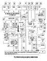
- FIG. 1shows one exemplary transportation security system in accordance with one embodiment.
- FIG. 2is a block diagram of the transportation security system depicted in FIG. 1 .
- FIG. 3is a block diagram of a Container Security Device (CSD).
- CSDContainer Security Device
- FIG. 4is a flowchart illustrating one exemplary method for detecting and registering a container intrusion signal.
- FIG. 5is a flowchart of method for detecting and registering a container intrusion signal by accelerometer.
- FIG. 6is a flowchart of method for detecting and registering a container intrusion signal by a light sensor.
- FIG. 7is a flowchart of method for detecting and registering a container intrusion signal by a strain gage.
- FIG. 8is a flowchart of method for detecting and registering a container intrusion signal by a smoke detector.
- FIG. 9is a flowchart of method for detecting and registering a container intrusion signal by a humidity sensor.
- FIG. 10is a flowchart of method for detecting and registering a container intrusion signal by a temperature sensor.
- FIG. 11is a flowchart of method for detecting and registering a container intrusion signal by a door-opening sensor.
- FIG. 12is a flowchart of method for detecting and registering a container intrusion signal by a microphone.
- FIG. 13is a flowchart of method for detecting and registering a container intrusion signal by a UMPR.
- FIG. 14is a schematic diagram illustrating exemplary parameters for measuring a digital signature.
- FIG. 15show a cross-sectional view of one exemplary Mass-tomograph in accordance with one embodiment.
- FIG. 16shows a cross-sectional view of the Mass-tomograph depicted in FIG. 15 when the container is steady.
- FIG. 17shows a cross-sectional view of the Mass-tomograph depicted in FIG. 15 when the container is moving.
- FIG. 18shows a block diagram of one exemplary bridge.
- FIG. 19shows a block diagram of the bridge, depicted in FIG. 18 , when stationary.
- FIG. 20shows a block diagram of one exemplary portative bridge depicted in FIG. 18 .
- FIG. 21shows a block diagram of one exemplary service bridge depicted in FIG. 18 .
- FIG. 22shows a diagramed depiction of one exemplary Network Operations Center depicted in FIG. 1 .
- FIG. 23shows a diagramed depiction of one exemplary NOC server depicted in FIG. 22 .
- FIG. 24shows a flowchart showing one exemplary method for monitoring container integrity.
- FIG. 25shows a diagramed depiction of personal conditions monitoring system.
- FIG. 1shows one exemplary transportation security system 100 in accordance with one embodiment.
- Each mode of transportatione.g., transportation by ship
- a ship 110is illustratively shown carrying a plurality of shipping containers 130 .
- Each shipping container 130has a Container Security Device (“CSD”) 140 that communicates with a Network Operations Center (“NOC”) 170 , preferably via a Bridge 150 .
- NOCNetwork Operations Center
- the CSD 140detects a break-in violation, an alert status is generated and transmitted to NOC 170 , via the Bridge 150 .
- the CSD 140communicates with the Bridge 150 using an Unlicensed International Frequency Band Local Area Communication Network 160 C.
- the CSD 140may communicate with the NOC 170 via a cellular communications channel 160 A or a satellite communication channel 160 B.
- the alert status generated by the CSD 140when onboard a ship for example, includes the identity of the container 130 , in which also is located, the location of the ship 110 , the time and date of the alert status generation, and a description of the alert status.
- the NOC 170upon receipt of the alert status, may either confirm or reject the alert status. If the alert status is confirmed, the NOC 170 may generate an alarm signal.
- FIG. 2is a block diagram further illustrating the transportation security system 100 of FIG. 1 .
- FIG. 2illustratively shows communication between CSD 140 , NOC 170 and Bridge 150 in further detail.
- the CSD 140is shown communicating with the NOC 170 via cellular 160 A or satellite 160 B communications.
- the Bridge 150is also shown communicate with the NOC 170 via cellular 160 A or satellite 160 B connection.
- the Bridge 150may also communicate with the NOC 170 via an Ethernet connection 160 D, for example.
- FIG. 3is a block diagram illustrates one exemplary CSD 300 .
- CSD 300may, for example, represent CSD 140 of FIG. 1 .
- the CSD 300includes a Sensor Block 310 , a local alert mechanism 320 , a Microcontroller 330 , a GPS receiver 340 , a Cellular Modem 350 A, a Satellite Modem 350 B, a wireless LAN (WLAN) Interface 350 C, an Antenna Block 360 and a Power Unit 370 .
- the WLAN Interface 350 Cuses one of the standard type Unlicensed International Frequency transceiver like Bluetooth Zigbee etc.
- the Sensor Block 310is illustratively shown with a Light Sensor 310 A, a Capacity Proximity Sensor 310 B, an Accelerometer 310 C, a Micro Power Radar (MPR) 310 D, an Inductive Sensor 310 E, a RFID reader 310 F, a Strain Gage 310 G.
- the Sensor Block 310may also include one or more of: a Piezosensor 310 H, an Ultrasonic Sensor 310 I, a Microphone 310 P, an Ultrasound Micropower Radar (UMPR) 310 J, an Infrared Sensor 310 K, a Door Opening Sensor 310 L, a Seal Break Sensor 310 M, a Sensor control parameters of surrounding 310 N, as shown in FIG. 4 .
- Sensor control parameters of surroundings 310 Nmay include one or more of: a Temperature Sensor, a Smoke Detector Sensor, a Humidity Sensor, etc.
- the Antenna block 360includes a GPS antenna 360 A, a Cellular antenna 360 B, a Satellite antenna 360 C, and a low power LAN antenna 360 D.
- microcontroller 330monitors output of sensor block 310 to determine an alert status. If an alert status is determined, microcontroller 330 may provide Cellular modem 350 A, Satellite modem 350 B and/or LAN interface 350 C with a formatted message packet. This message packet may, for example, be transmitted from the Antenna block 360 to either the Bridge 150 or the NOC 170 . Transmission message packets from the Bridge 150 and/or the NOC 170 (see FIG. 1 and FIG. 2 ) are received by the Antenna block 360 and directed to one or more of the Cellular modem 350 A, the Satellite modem 350 B and the LAN interface 350 C. Microcontroller 330 may then process the Bridge 150 and/or the NOC 170 message packet to receive information and/or instructions from the NOC 170 , for example.
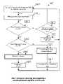
- FIG. 4is a flowchart illustrating one exemplary method 399 for detecting and registering container intrusion signals (e.g., alert statuses).
- Accelerometer 310 C, Piezosensor 310 H and Ultrasonic sensor 310 I, Microphone 310 P output signalsare monitored by the microcontroller 330 , which thus identifies sensors 310 that exceed one or more pre-set threshold levels.
- the microcontroller 330operates in a calibration mode.
- the container's 130 wallsmay be struck several time and ‘images’ of these hits may be recorded and stored in a pulling library of images 425 in the microcontroller 330 for use as calibration images pertaining to this particular container 130 .
- one or more exemplary images of intrusion or damage to the container 130may also be stored in the library of images 425 .
- the microcontroller 330identifies signals that exceed certain threshold levels. These signals may be separated by microcontroller 330 , in Step 400 , into a single hit signal 405 and/or a series of hit signals 407 . Within the microcontroller 330 , a Short Time Fast Fourier Analysis is used to process the single hit signal 405 , in Step 410 , and a Wavelet analysis may also be performed, in Step 415 . An image of the single hit signal is then created. Correlation Functions in Step 420 and Theory of Sample Recognition in Step 430 , are utilized to compare the hit image to the exemplary images stored within the library of images 425 . If the microcontroller 330 determines that the single hit image correlates with to the images of intrusion into a damaged container, a majority voting algorithm is applied to the single hit image. The majority voting algorithm is a part of an integrated sensor processing procedure 470 .
- the majority voting algorithmis based on major voting mark of unrelated criteria. Each criteria may be assigned positive and/or negative points.
- the majority voting algorithmis applied to the image of the single hit signal the decision about intrusion attempt is based on voting process based on sum of all points given during processing of the hit signal image. If the sum of total points given to the hit signal image indicates that an intrusion attempt took place, the single hit image is further subjected to the integrated sensor processing procedure 470 , which makes a decision as to if intrusion occurred.
- the majority voting algorithmmay also be applied to the series of hit signals 407 in Step 470 . If the sum of total points given during processing of the series of hit signals 407 indicates that intrusion, or even an intrusion attempt, occurred, the series of hit signals 407 are subjected to an integrated sensor processing procedure 470 which makes a decision as to if the intrusion occurred.
- the data processed by integrated sensor processing procedure 470is incomplete or inconsistent, this data is sent by the CSD 140 to the NOC 170 for a further analysis. In this case the NOC 170 (i.e., not the CSD 140 ) will make the decision as to if intrusion occurred.
- the microcontroller 330may also utilize correlation functions 420 to compare output from the Accelerometer 310 C and other sensors like the Piezosensor 310 H and/or the Ultrasonic sensor 310 I to an exemplary image that corresponds to a signal generating by a metal cutting instrument, for example, stored in the library of images 425 . If, in Step 420 , the microcontroller 330 determines that the intrusion signal 420 correlates to the stored signal image generated by a metal cutting instrument 425 , the intrusion signal is then further subjected to an integrated sensor processing procedure 470 that makes a decision as to if the intrusion took place.
- Output signals from the accelerometer 310 Cmay also be monitored by microcontroller 330 to detect vibration of the container wall.
- the microcontroller 330may process, in step 403 , the vibration signal 402 to produce a wavelet analysis and a “window” Fourier analysis for comparison, in step 440 , to one or more recorded images of library of images 425 to determine which mode of transportation is used to move the container 130 .
- the integrated sensor processing procedure 470may then be applied to these signals to determine the mode of transport or if an intrusion took place.
- An output signal from the light sensor's 310 Amay be monitored by the microcontroller 330 to determine intrusion or fire. For example, if the microcontroller 330 determines that the output signal indicates that the measured light within the container exceeds a certain rate of change threshold, the microcontroller 330 may initiate further analysis of the output signal, and/or other sensor signals, to determine if an intrusion is occurring, and/or if there is presence of smoke. If the microcontroller 330 determines that an intrusion has occurred and/or smoke is present, the output signal may be subjected to further processing by the integrated sensor procedure 470 to make the decision that intrusion occurred or not.
- Output signals from the capacitive proximity sensor's 310 B, Strain gage 310 G and RFID reader 310 F outputsalso may be monitored by the microcontroller 330 to detect addition or removal of objects from the container 130 .
- the output signalsmay, for example, be analyzed by the microcontroller 330 , Step 445 , to detect change in the cargo mass. If change in cargo mass is detected, the capacitive proximity sensor output may be subjected to the integrated sensor processing procedure 470 which makes a decision about the alert status of the container 130 .
- An output signal from the capacitive proximity's sensor 310 Bmay be monitored by the microcontroller 330 to determine if any objects are in close proximity to locks and seals of the container 130 . If any objects are detected in close proximity to the locks and the seals of the container 130 , the output signals from one or more sensors may be further analyzed within the microcontroller 330 to determine if a break-in has occurred. If a break-in is detected by the microcontroller 330 , further analysis of these signals may be made by the integrated sensor processing procedure 470 to make a decision as to if an intrusion occurred.
- Output signals from sensorsare monitored by the microcontroller 330 in control parameters of surrounding 310 N.
- These sensorsmay, for example, include a temperature sensor that produces an output signal which may be monitored by the microcontroller 330 to detect thermal excursions outside one or more predetermined temperature ranges and/or to detect rates of change in temperature that occur outside one or more predefined rates of change. If, for example, the microcontroller 330 determines that the sensed temperature is outside predetermined temperature ranges and/or that the rate of temperature change if outside these predetermined limits, output signals from one or more sensors will be further analyzed by the integrated sensor procedure 470 to decide if an intrusion occurred.
- an output signal from the smoke detector sensormay be monitored to determine if chemicals are present within the air, and/or air clarity inside the container 130 exceeds a predefined threshold level. If, for example, a chemical is detected within the air, output signals from one or more sensors will be further analyzed by the integrated sensor processing procedure 470 to make decision as to the container 130 alert status.
- an output signal from the UMPR 310 Jmay be monitored by the microcontroller 330 to detect presence of humans or animals within the container 130 . If, for example, presence of humans and/or animals is detected, the output signals from one or more sensors may be further processed by the integrated sensor procedure 470 to make a decision as to if an intrusion occurred.
- the UMPR 310 Jmay, for example, utilize the Doppler's effect to detect movement inside the container 130 .
- the UMPR 310 Jmay, for example include an ultrasonic transceiver. This sensor may also be used to detect force entry attempts into the container 130 , based upon registration of impact drilling, gas cutting, etc., by utilization of the UMPR 310 J as a highly sensitive UMPR-based microphone.
- the later purposeis accomplished by applying a procedure to determine, in Step 460 , the integrity of the container's wall. If the UMPR 310 J output data exceeds the threshold determined in Steps 460 and 465 , application of a procedure to determines the integrity of the walls and the cargo movement inside the container 130 may be applied. The output data of one or more sensors may then be further analyzed within the microcontroller 330 for presence of humans/animals or presence of wall integrity failure. If, for example, presence of humans/animals and/or wall destruction are detected, the output signals from one or more sensors 310 are subjected to the integrated sensor procedure 470 to make a decision as to if an intrusion occurred.
- Output signals from sensor MPR 310 Dmay be processed to produce a radioprint (e.g., radio-imprint) based upon locations of the objects inside the container 130 .
- a radioprinte.g., radio-imprint
- This radioprintmay be monitored by microcontroller 330 to detect deviations in object location, by comparing the radioprint to an initial radio print recorded during calibration, for example. Radioprints are build based on the analysis of all reflected signals, including signals reflected by objects that are not located in the direct field of the sensor. If, for example, microcontroller 330 detects deviation between a current radioprint and the radioprint recorded during calibration, the radioprints and output signals from other sensors may be subjected to the integrated sensor processing procedure 470 to determine if an intrusion occurred.
- Output signals from the infrared sensor's 310 Kmay be monitored by the microcontroller 330 to detect warm objects within the container. If, for example, the microcontroller 330 detects a warm object, the output signal from one or more sensors may be further analyzed, in Step 465 , within the microcontroller 330 to determine the presence of humans or animals by applying procedures that determines movement inside the container 130 . If, for example, humans or animals are detected, output signals from one or more sensors may be subjected to the integrated procedure 470 to make a decision as to if an intrusion occurred.
- An output signal from the GPS receiver 340may be monitored to determine a location of the CSD 140 , and further to determine if this location differs from a programmed route for the container 130 . If, for example, the microcontroller 330 determines that the current location differs from the programmed route, the output signal may be further analyzed, in Step 435 , to determine deviation from the programmed route. If, for example, significant deviation from the programmed route is detected, the output signals from one or more sensors may be subjected to the integrated sensor processing procedure 470 to make a decision as to if an intrusion occurred.
- the door opening sensor 310 L and the seal break sensor 310 Mare monitored by the microcontroller 330 to detect changes in integrity of the doors and seals of the container 130 . If the microcontroller 330 detects changes in integrity, the output signals from one or more sensors may be subjected to the integrated sensor processing procedure 470 to make a decision as to if an intrusion occurred.
- FIG. 5illustrates a flowchart of method for detecting and registering a container intrusion signal by accelerometer.
- accelerometer indicationsare monitored in two modes: Standby and Active.
- Standby modeaccelerometers are being checked in equal time periods, with frequency F 1 about 100 Hz in, instead of constant monitoring. Sensors go offline between checkpoints, and module's microcontroller, if not being used, enters sleep mode.
- accelerometersremain online from the moment of mode entry show in Step 508 to the moment when D remains below P 1 threshold shown in Step 513 for N measurement cycles as show in Steps 514 and 515 , when S (number of cycle when D less then P 1 ) exceeds N, then this in itself is the condition for exiting the Active mode as shown in Step 516 , then accelerometers 301 C are turned off. D is measured and determined in each measurement cycle shown in Step 510 and Step 511 and its maximum value maxD is recorded as shown in Step 509 . MaxD is verified upon exiting the Active mode.
- Step 517If the value MaxD exceeds P 2 threshold as shown in Step 517 , the majority algorithm of the integrated sensor processing procedure 470 indicates an impact against container's structure and time and amplitude of hit have fixed value as shown in Step 518 . If, however, the value MaxD does not exceed the threshold P 2 microcontroller returns into the Standby mode as shown in Step 519 .
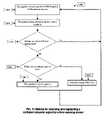
- FIG. 6illustrates a flowchart of method for detecting and registering a container intrusion signal by a light sensor.
- the algorithmis used to determine breaking in the container by changed light intensity inside the container as the result of both penetration of outside light and light flashes occurring in metal cutting tools operation.
- the light sensor's 310 A indicationsare read and analyzed with frequency about 3 Hz as show in Step 601 .
- Sampled sensor signal Ais filtered out and errors due to random deviations of sensor indications are eliminated as shown in Step 602 .
- Filtered signal A Fis compared in two stages with original sensor readings A*. If A F exceeds A* by more than 2% as show in Step 603 , the integrated sensor procedure 470 reports potential breaking in the container as show in Step 609 . If A F exceeds A* by more than 5% as shown in Step 604 , the integrated sensor procedure 470 reports the break in the container 130 as shown in Step 605 .
- Step 604the integrated sensor processing procedure 470 reports high chance of breaking in the container as show in Step 609 .
- Light sensoris recalibrated every 15 minutes in the process of its monitoring as show in Steps 606 , 607 , 608 and 610 . Recalibration is required because containers are not hermetically sealed, due to which light intensity inside of them could change in changing outside light conditions (at day/night).
- FIG. 7illustrates a flowchart of method for detecting and registering a container intrusion signal by a strain gage.
- the algorithmis used to record damage (alterations) to container structure.
- the strain gage 310 Gis queued with frequency about 1 kHz in 15 ms long sessions shown in Step 701 .
- Vector of measured results A ⁇ 15>is median filtered as shown in Step 702 .
- Measurement sessionsoccur with frequency about 3 Hz.
- Filtered signal A Fis compared in two stages with original sensor readings A*. If A F exceeds A* by more than 1% as show in Step 703 , the integrated sensor processing procedure 470 reports potential damage to container structure as shown in Step 707 . If A F exceeds A* by more than 3% as shown in Step 704 , the integrated sensor processing procedure 470 reports the break in the container 130 as shown in Step 708 .
- Step 704the integrated sensor processing procedure 470 reports potential damage to container structure as shown in Step 707 .
- Strain gageis recalibrated hourly in the process of its monitoring as shown in Steps 705 , 706 , 709 and 710 . This is required because changing ambient temperature (at day/night) causes strain of metal container walls.
- FIG. 8illustrates a flowchart of method for detecting and registering a container intrusion by s smoke detector sensor.
- the algorithmis used to determine smoke content in the container due to fire or breaking in using metal cutting instruments.
- the smoke detector sensor's 310 N indicationsare read and analyzed with frequency about 0.1 Hz shown in Step 801 .
- Sampled sensor signal Ais filtered out and errors due to random deviations of sensor indications are eliminated shown in Step 802 .
- Filtered signal A Fis compared in two stages with original sensor readings A*. If A F exceeds A* by more than 3% shown in Step 803 , the integrated sensor processing procedure 470 reports potential smoke content inside the container shown in Step 805 . If A F exceeds A* by more than 10%, the integrated sensor processing procedure reports smoke content inside the container shown in Step 806 . However, if A F does not exceed A* by more than 10%, the integrated sensor processing procedure 470 reports potential smoke content inside the container shown in Step 805 .
- the some detector sensor 310 Nis calibrated once during activation of security module.
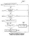
- FIG. 9illustrates a flowchart of method for detecting and registering a container intrusion signal by a humidity sensor.
- the algorithmis used to record relative humidity inside the container.
- the humidity sensor's 310 N indicationsare read and analyzed with frequency about 0.1 Hz as shown in Step 901 .
- Sampled sensor signalis filtered out and errors due to random deviations of sensor indications are eliminated shown in Step 902 .
- Filtered signalpasses two-stage evaluation. If relative humidity exceeds 85% as shown in Step 903 , the integrated sensor processing procedure 470 reports increased humidity inside the container shown in Step 906 . If relative humidity exceeds 95% as shown in Step 904 , the integrated sensor processing procedure reports high humidity inside the container as shown in Step 905 . However, if relative humidity does not exceed 95% as shown in Step 904 , the integrated sensor processing procedure 470 reports increased humidity inside the container shown in Step 906 .
- FIG. 10illustrates a flowchart of method for detecting and registering a container intrusion signal by a temperature sensor. Aside from recording the temperature inside the container in order to manage cargo storage conditions, the algorithm is able to monitor the rate of temperature change.
- the temperature sensor's 310 N indicationsare read and analyzed with frequency about 0.3 Hz as shown in Step 1001 .
- Sampled sensor signal Ais filtered out and errors due to random deviations of sensor indications are eliminated as shown in Step 1002 .
- Filtered signal A Fis compared in two stages with original sensor readings A*. If A F exceeds A* by more than 2° C. shown in Step 1003 , the integrated sensor processing procedure 470 reports temperature change inside the containers shown in Step 1007 . If A F exceeds A* by more than 5° C. as shown in Step 1006 , the integrated signal processing procedure 470 reports drastic change of temperature inside the container shown in Step 1009 . However, if A F does not exceed A* by more than 5° C.
- Step 1006the integrated sensor processing procedure 470 reports temperature change inside the containers shown in Step 1007 .
- Temperature sensoris recalibrated every 15 minutes in the process of its monitoring shown in Steps 1004 , 1005 , 1008 and 1110 . Recalibration is required because containers heat up and cool down in a broad temperature range during day/night cycle.
- FIG. 11illustrates a flowchart of method for detecting and registering a container intrusion signal by an incremental door opening sensors. In order to obtain more reliable judgment, two sensors are installed per container door.
- the door opening sensors 310 Lare queued with frequency 0.3 Hz.
- each sensoris queued thrice as shown in Step 1101 , after which each sensor's condition is determined using majorization as part of the integrated sensor processing procedure 470 as shown in Step 1102 . Based on obtained values, a judgment is drawn about condition of each container door as shown in Step 1103 . If both sensors indicate closed door as shown in Step 1104 , the door is reported to be closed. If both sensors indicate opened door as shown in Step 1104 , the door is reported to be opened as shown in Step 1106 . If sensor indications are inconsistent, sensor signal processing procedure reports potential opening of the door as shown in Step 1105 .
- FIG. 12illustrates a flowchart of method for detecting and registering a container intrusion signal by a microphone, which enables CSD to record noise caused by container breaking tools, and to determine possible type of tool.
- the microphone 310 Pis queued in sessions in 2 second intervals. This saves CSD power while avoiding the danger of missing the noise of tools' operation.
- Measurement session Tlasts 0.2 seconds as shown in Step 1201 .
- amplitude of microphone signalis verified across the entire frequency band. If input signal A inp is below preset threshold A min as shown in Step 1202 , subsequent signal processing is skipped until next measurement cycle as shown in Step 1201 . Otherwise, power of received signal
- P A1 T ⁇ ⁇ T ⁇ A inp 2 ⁇ d t is evaluated. If signal power exceeds preset threshold P A >P min , judgment is drawn about presence of noise correspondent to breaking in the container as shown in Step 1203 . Second level of processing takes place then, which includes spectrum analysis of signal power in order to determine the type of tool used to break in the container as show in Step 1205 . In this connection, bands exhibiting signal amplitude above preset threshold A inp f >A min f are gated out across the entire frequency range. Spectrum power of sound
- FIG. 13illustrates a flowchart of method of detecting and registering a container intrusion signal based on UMR.
- UMPRenables to construct a unique digital imprint of container interior, representing arrangement of items within radar coverage. The imprint would change reflecting changes in arrangement of interior items.
- the UMPR 310 JIn order to obtain the imprint, the UMPR 310 J emits 2 ms long pulses in ultrasonic frequency, such as 40 kHz as shown in Step 1301 . Meanwhile, the UMPR 3103 receiver stays idle. Emitted signal reflects repeatedly from container interior items and then returns to the UMPR 310 J where it is received by ultrasonic receiver. Receiver goes online for 50 ms after the pulse has been sent as shown in Step 1302 . Changes in amplitude of received signal for this period are the imprint of container interior.
- ultrasonic frequencysuch as 40 kHz
- UMPR receiver signalis sampled with at least double frequency of emitted signal.
- Obtained set of N values Y ⁇ N>is compared against reference imprint X ⁇ N> using correlation functions as shown in Step 1303 .
- Step 1304a judgment is drawn about changes in container interior as shown in Step 1305 .
- the accelerometers 310 Care included within CSD 140 and are used to create a Digital Signature (DS) and may be used to identify location of cargo within the container.
- FIG. 14is a schematic diagram illustrating exemplary parameters that may be used to form this DS.
- Mis the mass of the cargo
- Rmrepresents the coordinates of the center of mass within the body frame, which is strictly connected with the container itself
- Ix, Iy, Izare components of the container moment of inertia, which characterize the mass distribution with respect to the center of mass.
- DSis thus defined by this parameters set which may define the expected motion of the container. Changes in one or more of these measured parameters may, therefore, correspond to certain events during cargo transportation. For example, if DS has not changed, the cargo is intact. If, M and Ix, Iy, Iz are the same but Rm has changed, the cargo may not be stolen or damaged, but may have moved within the container 130 (i.e., the coordinates of the center of mass Rm change as the cargo moves within the container). It may, therefore, be necessary to check fastenings of the cargo within the container.
- parameter Mdoes not change, but parameters Ix, Iy, Iz and Rm have changed, it is probably that the cargo has not been stolen (it can be precisely determined based on the degree of the parameters change). However, it is also possible that a partial destruction of the cargo took place (e.g., damage resulting from inaccurate unloading). Change of the moment of inertia with respect to the center of mass may occur due to this destruction. If all parameters of the DS have changed, it is likely that the container has been tampered with. The determination of DS allows not only to reveal theft without opening the container, but may also provide continual monitoring of the cargo's condition.
- the accelerometers 310 Cas shown in FIG. 3 , that are included within the CSD 140 , form a Mass-tomograph 1500 , as shown in FIG. 15 .
- the plurality of accelerometers that form the Mass-tomographare coupled to walls of the container 130 .
- the Mass-tomograph 1500is used to construct a spatial picture of mass distribution within the container 130 .
- FIG. 15shows a cross-sectional view of one exemplary Mass-tomograph 1500 in accordance with one embodiment.
- Mass-tomograph 1500may, for example, be used to subtract effects of the surroundings on the accelerometers measurements.
- the initial calibration of accelerometersmay occur without any cargo in the container.
- a second round of measurementsmay occur when an object or a cargo (e.g., cargo 1510 ) is placed inside the container 130 .
- the calibration measurements of the accelerometersare subtracted from the second round of measurements to eliminate influence of the container itself, and the accelerometer measurements are thus only determined for the object 1510 mass.
- FIG. 16shows a cross-sectional view of one exemplary Mass-tomograph 1600 that is external to container 130 and when the container 130 is in steady position.
- the Mass-tomographis used as a device to obtain imaging of the contents of the container.
- the mass-tomograph 1600monitors the whole container 130 .
- the quality of the spatial mass distribution of the container massdepends on two parameters: the accuracy of accelerometers and the distance, laccel 1620 , between adjacent accelerometers 310 C that form the Mass-tomograph 1600 .
- FIG. 17shows a cross-sectional view of one exemplary Mass-tomograph 1700 when the container 130 is moving.
- Mass-tomograph 1700may, for example represent mass-tomograph 1600 , FIG. 16 .
- the mass-tomograph 1700scans the container 130 , as the container 130 moves gradually through the Mass-tomograph 1700 ; in this example the container 130 moves with a steady speed Vcont 1720 .
- a high quality spatial mass distribution inside the container 130may be determined, since the quality of spatial mass distribution depends only on the accuracy of accelerometers; the perceived distance laccel 1620 between adjacent accelerometers will be minimal due to the movement of the container.
- the microcontroller 330activates one or more local alert mechanisms (e.g., sound devices 320 A and/or light device 320 B, as shown in FIG. 3 ) that generate a local alarm signal.
- the microcontroller 330may also activate transceivers 350 A- 350 C to transmit a message that includes this alert via antennas 360 B- 360 D to the Bridge 150 and/or the NOC 170 .
- the microcontroller 330also determines time intervals used to activate the transceivers 350 A- 350 C during communication with the Bridge 150 or the NOC 170 . In one example, these time intervals may be determined by the NOC 170 .
- the CSD 140may be coupled to the wall of the container 130 by Rare Earth Magnets, Double-Stick Tape and/or Hot-Glue.
- the power unit 370 of the CSD 140may include one or more storage batteries 370 A.
- the power unit 370may also be configured to receive electrical power from a power source of the cargo transport vehicle. In this case, if the power source is interrupted, the power unit 370 may revert to use of the storage batteries 370 A and/or Solar power, for example. In the event of a power interruption or if the storage battery charge falls below a threshold level, the CSD 140 may transmit, via antennas 360 , a power interrupt alarm to the Bridge 150 and/or the NOC 170 .
- the microcontroller 330may also implement power-management techniques to reduce power consumption. For example, one or more time window(s) may be specified, during initialization process or via transceivers 350 A- 350 C, to define activation times for one or more components of CSD 140 .
- the CSD 140may switch into a sleep (suspend) mode to avoid unnecessary power utilization. In fact, sleep mode may account for a significant part of the life of the CSD 140 ; the CSD 140 may operate over several years without need of storage battery replacement. In one example of operation, the CSD 140 remains awake (i.e., does not switch to sleep mode) when communicating with the Bridge 150 and/or the NOC 170 .
- the CSD 140may also switch from sleep to awake mode if any one anti-tamper sensor of block 310 exceeds a certain threshold level.
- FIG. 18shows a block diagram illustrating one exemplary Bridge 1800 .
- Bridge 1800may, for example, represent bridge 150 of FIG. 1 .
- the Bridge 1800includes a Microcontroller unit 1810 , GPS receiver 1830 , Cellular Modem 1840 A, Satellite Modem 1840 B, WLAN Interface 1840 C, Ethernet interface 1850 A, User interface 1850 B, External connection interface 1850 C, Antennas Block 1860 and Power Unit 1870 .
- the block of Antennas 1860includes GPS antenna 1860 A, Cellular antenna 1860 B, Satellite antenna 1860 C, and International Frequency Band Local Area Communication antenna 1860 D.
- the Cellular modem 1840 Ais utilized to communicate with the NOC 170 via cellular communication channel 160 A, for example.
- the Satellite modem 1840 Bis utilized to communicate with the NOC 170 via satellite communication channel 160 B, for example.
- the WLAN interface 1840 Cis utilized to communicate with the CSD 140 via LAN 160 C.
- the CSD 140communicates to the NOC 170 via the Bridge 1800 . Communication from the CSD 140 to the NOC 170 is less costly when the Bridge 1800 is utilized to relay the communication. In one example, it saves energy compare to when the CSD communicates with the NOC 170 directly via cellular or satellite communications channels. In one example, the CSD 140 transmits the system status, including any alert status, to the Bridge 1800 upon request of the NOC 170 .
- the Bridge's 1800includes a power unit 1870 which may receive power from a power network 1870 B.
- power unit 1870may be configured to switch over to utilize Storage batteries 1870 A.
- This power interruptionmay be detected by the microcontroller unit 1810 , for example, which may transmit an alarm message to the NOC 170 .
- the alarm messagemay, for example, identify the bridge 1800 by an identification code, the location of the ship provided by the GPS receiver 1830 , the date and time of the alarm, and further description of the alarm event (e.g., loss of ship's power).
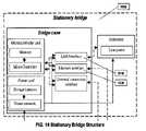
- FIG. 19shows a block diagram of one exemplary Stationary Bridge 1900 according to one embodiment.
- the Stationary Bridge 1900may be placed in the areas of high container concentration, such as places of consolidation/deconsolidation of containers, ports, terminals, etc.
- Stationary Bridge 1900may be used for continuous communication with the NOC 170 .
- Stationary Bridge 1900includes the WLAN Interface 1910 and the Ethernet interface 1920 .
- Stationary Bridge 1900may not include a user interface. Further, since the geographical location of the Stationary Bridge 1900 remains the same, it may not require a GPS receiver.
- FIG. 20shows a block diagram of one exemplary Portative Bridge 2000 according to one embodiment.
- the Portative Bridge 2000may be used where containers are transported, such as on ships, trains, etc.
- the Portative Bridge 2000includes a GPS receiver 2010 , a Cellular Modem 2020 A, a Satellite modem 2020 B, a WLAN 2020 C, an External connection interface 2030 and an Antenna Block 2060 .
- the Portative Bridge 2000uses cellular 160 A and satellite 160 B communication channels.
- the Portative Bridge 2000may not have a user interface.
- FIG. 21shows a block diagram of one exemplary Service Bridge 2100 according to one embodiment.
- the Service Bridge 2100may be used to support and communicate with one or more CSDs 140 .
- the Service Bridge 2100may include a cellular modem 2120 A, a satellite-modem 2120 B, a WLAN 2120 C, a user interface 2130 A, an External connection interface 2130 B and an Antenna block 2160 .
- the service Bridge 2100may communicates with the NOC 170 via other Stationary and/or Portative Bridges (e.g., portative bridge 1100 ) using UBFT 160 C and/or through the Cellular 160 A and/or satellite 160 B communication channels.
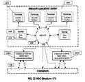
- FIG. 22shows a diagramed depiction of one exemplary NOC 2200 .
- the NOC 2200may, for example, represent NOC 170 of FIG. 1 .
- the NOC 2200may include a plurality of terminals 2210 and servers 2220 interconnected via Internet 2250 .
- the servers 2220may include a Data Base 2230 .
- the data base 2230may, for example, be used to store sensor data and may contained archives of container events received from one or more CSDs 140 .
- the data base 2230may also store information pertaining to the location and condition of cargo containers.
- the NOC 170may use the services of a Commercial world wide digital cellular communication operator 2260 A, configured to communicate with the CSD 140 and/or the Bridge 150 via the cellular communication channels 160 A.
- the NOC 170may also use the service of a Commercial world wide satellite digital communication operator 2260 B that configured to communicate with the CSD 140 and/or the Bridge 150 via satellite communication channels 160 B.
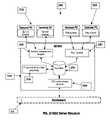
- FIG. 23illustrates a more detailed diagram of the system server 2220 and its interaction with other system elements.
- the serveris comprised of a software complex and the database 2230 .
- serverincludes following software: database, program for communication with CSD 2380 , programs for communication with operator terminals 2350 , and program for analysis of CSD sensor data 2370 .
- the database 2230contains identification and custom data of secured objects, their condition, CSD operation parameters and commands issued to security modules by system operators.
- the databasecan also include data from CSD sensors for its further detailed examination by server means.
- the CSD communication program 2380receives CSD data during communication session established directly or via bridge, moves the data to server database, extracts operator commands and required service data from the database and sends them to modules.
- the operator terminal communication program 2350could be used for data exchange with custom terminal programs installed on user computers, or for development of web interface accessible by any authorized user from any computer without dedicated software installed. Accordingly, there can be two types of operator terminals: computer with terminal application installed 2310 and/or computer with a web browser 2330 .
- the computer with terminal application installed 2310has the advantage of quick data exchange.
- the computer with web browser 2330provides easy access to the system. Both applications handle operator commands issuing to CSD, their saving in the database and transfer of information about secured objects from database to operator terminals.
- the CSD sensor data analysis program 2370is used when CSD software is incapable to process sensor data to the level sufficient for deciding on condition of secured object due to its limited computing performance.
- the CSD sensor data analysis programextracts CSD sensor data from the database, processes it and concludes about the condition of CSD and secured object. Calculation results are stored in server database 2230 .
- FIG. 24shows a flowchart illustrating one exemplary method 2399 for monitoring container integrity in accordance with one embodiment.
- the initiation step 2400includes a data packet that is download into CSD's 140 microcontroller 330 .
- the data packetincludes certain parameters that remain unchanged during the lifetime of the CSD 140 . These parameters include an identification code for the CSD 140 , an address of a server that may be used to communicate with the CSD, and associated parameters of communication, etc.
- the initiation of the CSD 140may, for example, be done by the Bridge 150 or other equipment (not shown).
- the operation of the CSD 140is cyclic. Each CSD cycle lasts one container trip/route (i.e., from the moment of uploading to before the unloading of the container 130 ).
- the CSD 140is activated by the Bridge 150 or the NOC 170 .
- the CSD's microcontroller 330is cleared of any previously stored information. New information pertaining to the container's route and movement schedule, as well as parameters and logic that use regimes pertaining to the container's 130 safety, are downloaded into the microcontroller 330 .
- the CSDis placed in the active mode, in Step 2402 , by the Bridge 150 or by the server 2220 of the NOC 170 .
- condition of the container 130 and its cargoare continually or periodically monitored.
- the CSD microcontroller 330checks for an alert status from the integrated sensor processing procedure 470 in Step 2404 .
- the microcontroller 330checks if it is a time for the packet of the information pertaining to the container's condition to be sent to the NOC 170 .
- the microcontroller 330also checks if the request for communication with the NOC 170 was received from the Bridge 150 . If the NOC 170 receives a message containing an alert status from the CSD 140 , the NOC 170 sends a request to the CSD's 140 GPS receiver 340 . In response to this request, the GPS receiver determines the geographical location of the CSD 140 in Step 2410 , and sends this location information to the microcontroller 330 .
- the CSD 140may also determine its geographical location by requesting location information from the bridge 150 .
- the microcontroller 330may also periodically request location information from either the GPS receiver 340 or the bridge 150 .
- the microcontrollersends the request to the GPS receiver in Step 2420
- the GPS receiver 340determines the geographical position of the container 130 in Step 2422 .
- Step 2412the CSD 140 establishes connection to the NOC 170 .
- the CSD 140communicates with the NOC 170 through the Bridge 150 using Unlicensed International Frequency Band Local Area Communication Network 160 C.
- the CSD 140may communicate with the NOC 170 via cellular communications channels 160 A or satellite communications channels 160 B.
- the CSD's communication via the Bridge 150may be less expensive and may also save energy, as compared to contacting the NOC 170 directly via cellular 160 A or satellite 160 B communication channels.
- the CSD 140sends the information packet to the NOC 170 .
- This packetmay include one or more of the transmission time, the channel of communication, level of batteries charge, location of the CSD etc.
- the NOC 170requests that the CSD 140 perform certain commands, in Step 2414 , pertaining to further operation of the CSD 140 , including a regime for monitoring containers safety, etc.
- the CSD 140may receive a command from the NOC 170 to deactivate the CSD 140 .
- step 2416the CSD verifies that the received command is a deactivation command and, if it is, the CSD deactivates in Step 2418 ; otherwise Steps 2404 - 2416 are performed continually until a deactivation command is received.
- the CSD 140may deactivate at route completion before the cargo is unloaded. During this deactivation period, the CSD 140 ceases to monitor containers and cargo safety.
- Proposed systemcould be employed not only for providing security to general ISO containers, but also for ensuring safety of other moving objects, such as vehicles, boats, etc., as well as of remote fixed objects, e.g. country houses. The difference in these cases is the mobile module at secured object.
- FIG. 25illustrates the diagram of one potential system application—a personal conditions monitoring system 2500 .
- the systemcould be employed for monitoring health conditions and accumulated workload of physically weakened persons, those in need for constant medical supervision, as well as specialists directly engaged in potentially dangerous activities. Examples include military and special services personnel, professional drivers, athletes, alpinists, etc.
- security modulecould be used for monitoring personal conditions, accumulated physical load, for recording events occurred to the person (falling, impacts, changes of position of the body, traveling in transport, etc.), as well as for recording events in the immediate vicinity of the person (gunshots, explosions, changes of temperature and humidity, etc.).
- Monitoring modulefor example could be the CSD 140 , which includes: the sensor array 310 and ADC 320 , computing subsystem comprised of the microcontroller 330 and memory unit, communication subsystem including the transceiver 350 and the antenna 360 , and power subsystem with replaceable batteries 370 .
- the combination of sensorsis determined by the purpose of the module.
- the accelerometers 310 Ccould be used as they enable to monitor position and movement of a person, his pulse and a number of events in the surroundings, and electrodes for measuring amplitude-time parameters of heart biopotentials (ECG) and electrical impedance of the body to automatically estimate functional state of cardiovascular system on the basis of data obtained in examination of electrical activity of the heart, type of vegetative regulation of the rhythm and central gemodynamic parameters obtained in automatic syndromal ECG diagnostics, heart rate variability analysis and impedance gram analysis of the body.
- ECGheart biopotentials
- monitoring modulecontinuously monitors sensor indications, performs initial processing of measured values, concludes about the condition of the person or events occurred to him, and sends data to the server 2220 .
- Datais sent to server if personal conditions have changed or when certain emergency events occur, and periodically, e.g. hourly. Data is transferred over a wireless Wi-Fi based link 160 C or using cellular networks 160 B.
- the server 2220receives information from the monitoring module 140 , performs its additional processing if necessary, and stores it in the database 2230 . In emergency cases, server sends SMS notification to phone numbers specified for the person.
- Terminal programdisplays all data on the terminal 2310 available at the server in real-time, notifying operator in emergency if necessary.
Landscapes
- Business, Economics & Management (AREA)
- Physics & Mathematics (AREA)
- General Physics & Mathematics (AREA)
- Engineering & Computer Science (AREA)
- Emergency Management (AREA)
- General Health & Medical Sciences (AREA)
- Economics (AREA)
- Child & Adolescent Psychology (AREA)
- Health & Medical Sciences (AREA)
- Human Resources & Organizations (AREA)
- Marketing (AREA)
- Strategic Management (AREA)
- General Business, Economics & Management (AREA)
- Quality & Reliability (AREA)
- Theoretical Computer Science (AREA)
- Operations Research (AREA)
- Tourism & Hospitality (AREA)
- Entrepreneurship & Innovation (AREA)
- Development Economics (AREA)
- Radar, Positioning & Navigation (AREA)
- Computer Networks & Wireless Communication (AREA)
- Burglar Alarm Systems (AREA)
- Alarm Systems (AREA)
Abstract
Description
is evaluated. If signal power exceeds preset threshold PA>Pmin, judgment is drawn about presence of noise correspondent to breaking in the container as shown in
is calculated for gated bandwidth ΔF. Through signal processing, a spectrum power array at different frequency bands S is generated. Each container-breaking tool is characterized by its own array of sound spectrum power Si*, limited from below. Tool of breaking is determined in comparing arrays S and Si*. If arrays S included in an array of sound spectrum power Sias shown in
Value of correlation function formulated using least squares method
is compared against the limit FMAX, and if the limit is exceeded as shown in
Claims (7)
Priority Applications (6)
| Application Number | Priority Date | Filing Date | Title |
|---|---|---|---|
| US11/343,560US7990270B2 (en) | 2005-01-28 | 2006-01-30 | Transportation security system and associated methods |
| US13/195,637US8164458B2 (en) | 2005-01-28 | 2011-08-01 | Transportation security system and associated methods |
| US13/444,690US20120249326A1 (en) | 2005-01-28 | 2012-04-11 | Transportation security system and associated methods |
| US13/767,736US8643503B2 (en) | 2005-01-28 | 2013-02-14 | Transportation security system and associated methods |
| US14/165,387US8907793B2 (en) | 2005-01-28 | 2014-01-27 | Transportation security system and associated methods |
| US14/565,339US9262896B1 (en) | 2005-01-28 | 2014-12-09 | Transportation security system and associated methods |
Applications Claiming Priority (2)
| Application Number | Priority Date | Filing Date | Title |
|---|---|---|---|
| US64826005P | 2005-01-28 | 2005-01-28 | |
| US11/343,560US7990270B2 (en) | 2005-01-28 | 2006-01-30 | Transportation security system and associated methods |
Related Child Applications (1)
| Application Number | Title | Priority Date | Filing Date |
|---|---|---|---|
| US13/195,637ContinuationUS8164458B2 (en) | 2005-01-28 | 2011-08-01 | Transportation security system and associated methods |
Publications (2)
| Publication Number | Publication Date |
|---|---|
| US20060181413A1 US20060181413A1 (en) | 2006-08-17 |
| US7990270B2true US7990270B2 (en) | 2011-08-02 |
Family
ID=36815120
Family Applications (3)
| Application Number | Title | Priority Date | Filing Date |
|---|---|---|---|
| US11/343,560Active - Reinstated2029-02-21US7990270B2 (en) | 2005-01-28 | 2006-01-30 | Transportation security system and associated methods |
| US13/195,637Expired - Fee RelatedUS8164458B2 (en) | 2005-01-28 | 2011-08-01 | Transportation security system and associated methods |
| US13/444,690AbandonedUS20120249326A1 (en) | 2005-01-28 | 2012-04-11 | Transportation security system and associated methods |
Family Applications After (2)
| Application Number | Title | Priority Date | Filing Date |
|---|---|---|---|
| US13/195,637Expired - Fee RelatedUS8164458B2 (en) | 2005-01-28 | 2011-08-01 | Transportation security system and associated methods |
| US13/444,690AbandonedUS20120249326A1 (en) | 2005-01-28 | 2012-04-11 | Transportation security system and associated methods |
Country Status (1)
| Country | Link |
|---|---|
| US (3) | US7990270B2 (en) |
Cited By (23)
| Publication number | Priority date | Publication date | Assignee | Title |
|---|---|---|---|---|
| US20110133888A1 (en)* | 2009-08-17 | 2011-06-09 | Timothy Dirk Stevens | Contextually aware monitoring of assets |
| US20110273852A1 (en)* | 2007-10-05 | 2011-11-10 | Robert Debrody | Reusable Bolt Electronic Seal Module with GPS/Cellular Phone Communications & Tracking System |
| US20120089540A1 (en)* | 2010-10-12 | 2012-04-12 | Manivilovski Mike | Cart systems and methods for delivering pharmaceutical items to a retail seller |
| US8164458B2 (en)* | 2005-01-28 | 2012-04-24 | Systems Microtechnologies, Inc. | Transportation security system and associated methods |
| US8314704B2 (en) | 2009-08-28 | 2012-11-20 | Deal Magic, Inc. | Asset tracking using alternative sources of position fix data |
| US8334773B2 (en) | 2009-08-28 | 2012-12-18 | Deal Magic, Inc. | Asset monitoring and tracking system |
| US8432274B2 (en) | 2009-07-31 | 2013-04-30 | Deal Magic, Inc. | Contextual based determination of accuracy of position fixes |
| US8456302B2 (en) | 2009-07-14 | 2013-06-04 | Savi Technology, Inc. | Wireless tracking and monitoring electronic seal |
| US20130154829A1 (en)* | 2005-01-28 | 2013-06-20 | Kirill Mostov | Transportation Security System and Associated Methods |
| US8593280B2 (en) | 2009-07-14 | 2013-11-26 | Savi Technology, Inc. | Security seal |
| US8854029B2 (en) | 2007-10-24 | 2014-10-07 | Radical Development Holding S.A. | System and method for space control and remote monitoring |
| US8881540B1 (en) | 2014-01-27 | 2014-11-11 | Tcp Reliable, Inc. | Monitoring temperature-sensitive cargo with automated generation of regulatory qualification |
| US20140361894A1 (en)* | 2013-04-26 | 2014-12-11 | Electronics And Telecommunications Research Institute | Security apparatus and system using millimeter-wave communications, and method for the same |
| US8935934B2 (en) | 2013-03-12 | 2015-01-20 | Tcp Reliable, Inc. | Monitoring temperature-sensitive cargo with automated generation of regulatory qualification |
| US9501920B2 (en) | 2012-06-22 | 2016-11-22 | K.L. Harring Transportation LLC | Cargo tracking and monitoring system |
| US20170169369A1 (en)* | 2015-12-15 | 2017-06-15 | International Business Machines Corporation | Image-based risk estimation |
| US9928726B2 (en) | 2005-02-08 | 2018-03-27 | Ftc Sensors, Llc | Sensor and transmission control circuit in adaptive interface package |
| US10126805B2 (en) | 2016-08-08 | 2018-11-13 | Blackberry Limited | Triggering transition of a device between states |
| US11404151B2 (en)* | 2010-12-16 | 2022-08-02 | Tridentify AB | Medical package, system and method for managing medical package |
| US11468755B2 (en) | 2018-06-01 | 2022-10-11 | Stress Engineering Services, Inc. | Systems and methods for monitoring, tracking and tracing logistics |
| US11605285B1 (en)* | 2020-11-06 | 2023-03-14 | Vanguard Products Group, Inc. | Merchandise handling alert apparatus |
| US11773626B2 (en) | 2022-02-15 | 2023-10-03 | Stress Engineering Services, Inc. | Systems and methods for facilitating logistics |
| US12167186B2 (en) | 2016-10-21 | 2024-12-10 | Silicon Controls Pty Ltd. | Systems and methods for improved asset monitoring via orientation measurement |
Families Citing this family (79)
| Publication number | Priority date | Publication date | Assignee | Title |
|---|---|---|---|---|
| DE20319131U1 (en)* | 2003-12-10 | 2004-03-18 | KNÜPFER, Jürgen | Device for monitoring of cargo (load monitoring) |
| US7880767B2 (en)* | 2005-08-22 | 2011-02-01 | Andrew Chinigo | Security system for mass transit and mass transportation |
| US7636033B2 (en) | 2006-04-05 | 2009-12-22 | Larry Golden | Multi sensor detection, stall to stop and lock disabling system |
| US7737840B2 (en)* | 2006-04-10 | 2010-06-15 | The Boeing Company | Container security system |
| US20080036593A1 (en)* | 2006-08-04 | 2008-02-14 | The Government Of The Us, As Represented By The Secretary Of The Navy | Volume sensor: data fusion-based, multi-sensor system for advanced damage control |
| US20080047350A1 (en)* | 2006-08-23 | 2008-02-28 | University Of Washington | Use of ultrasound for monitoring security of shipping containers |
| US7978065B2 (en)* | 2006-09-13 | 2011-07-12 | Trackpoint Systems, Llc | Device, system and method for tracking mobile assets |
| US8803683B2 (en) | 2006-09-13 | 2014-08-12 | Trackpoint Systems, Llc | System, method, and device for measuring and reporting changing levels of liquids in storage tanks |
| US20080129490A1 (en)* | 2006-10-06 | 2008-06-05 | Linville Jeffrey E | Apparatus and Method for Real Time Validation of Cargo Quality for Logistics Applications |
| EP2100255A4 (en)* | 2006-12-06 | 2013-12-04 | Kirsen Technologies Corp | SYSTEM AND METHOD FOR DETECTING OBJECTS AND HAZARDOUS SUBSTANCES |
| US20100283608A1 (en)* | 2007-01-04 | 2010-11-11 | Honeywell International Inc. | Intrusion Warning and Reporting Network |
| US8803685B2 (en)* | 2007-02-01 | 2014-08-12 | Angel Secure Networks, Inc. | Container defense system |
| US20080231454A1 (en)* | 2007-03-23 | 2008-09-25 | Diamond Arrow Communications L.L.C. | Cargo Container Monitoring Device |
| US20080231438A1 (en)* | 2007-03-23 | 2008-09-25 | Diamond Arrow Communications L.L.C. | Cargo Container Monitoring System |
| US7696869B2 (en) | 2007-04-05 | 2010-04-13 | Health Hero Network, Inc. | Interactive programmable container security and compliance system |
| US7692541B1 (en)* | 2007-05-31 | 2010-04-06 | Gianni Arcaini | Method and apparatus for detecting container breach via visual cues |
| EP2223152A4 (en) | 2007-11-20 | 2011-04-20 | Kirsen Technologies Corp | APPARATUS FOR DETECTION AND REMOTE MONITORING OF CONCEALED OBJECTS |
| US8571829B2 (en)* | 2008-07-11 | 2013-10-29 | University Of Washington Through Its Center For Commercialization | Detecting objects in shipping containers by vibration spectral analysis |
| US8957771B2 (en)* | 2008-07-17 | 2015-02-17 | Consumer Safety Technology, Inc. | Apparatus, system, and method for implementing and monitoring breath alcohol testing programs, usually from a fixed point location, such as a home |
| US8284049B2 (en)* | 2008-10-08 | 2012-10-09 | Kwj Engineering | Sensing and reporting devices, systems and methods |
| US20100141445A1 (en)* | 2008-12-08 | 2010-06-10 | Savi Networks Inc. | Multi-Mode Commissioning/Decommissioning of Tags for Managing Assets |
| ATE522896T1 (en)* | 2009-02-25 | 2011-09-15 | Fiat Ricerche | CONTAINER TRACKING SYSTEM |
| WO2010127404A1 (en) | 2009-05-08 | 2010-11-11 | Michael Peter Wildon | Identification device, system and method |
| CN102472517B (en) | 2009-07-13 | 2016-02-03 | 开利公司 | Transport refrigeration system, transport refrigeration unit and method thereof |
| US9958198B2 (en) | 2009-07-13 | 2018-05-01 | Carrier Corporation | Embedded cargo sensors for a refrigeration system |
| US20110050397A1 (en)* | 2009-08-28 | 2011-03-03 | Cova Nicholas D | System for generating supply chain management statistics from asset tracking data |
| US20110054979A1 (en)* | 2009-08-31 | 2011-03-03 | Savi Networks Llc | Physical Event Management During Asset Tracking |
| KR101147683B1 (en)* | 2009-10-08 | 2012-05-22 | 최운호 | System for Tracking and Securing Container and Logistics Using Biometric Identification Card and CSD |
| FR2957213A1 (en)* | 2010-03-05 | 2011-09-09 | Thales Sa | RADIOFREQUENCY CIRCUIT BOOST IN A SATELLITE COMPRISING A THERMAL CONTROL SYSTEM BY ALARM SIGNAL GENERATED BY POWER REFLECTION |
| US9442178B2 (en)* | 2010-04-23 | 2016-09-13 | Qualcomm Incorporated | Hybrid tracking device |
| US8570993B2 (en)* | 2010-05-20 | 2013-10-29 | At&T Mobility Ii Llc | Wi-Fi intelligent selection engine |
| DE102010044735A1 (en)* | 2010-09-08 | 2012-03-08 | Glp German Light Products Gmbh | Transportable device with a controlled logging functionality |
| US20120112902A1 (en)* | 2010-11-08 | 2012-05-10 | System Planning Corporation | System For Multiple Layered Security Within A Cargo Container |
| US8797160B1 (en)* | 2011-01-06 | 2014-08-05 | Globaltrak, Llc | Apparatus for tamper proof security mechanism and tamper evident indicator |
| EP2506229B1 (en) | 2011-03-28 | 2015-05-06 | C.R.F. Società Consortile per Azioni | A container anti-intrusion sensor device |
| US9307756B2 (en)* | 2011-10-26 | 2016-04-12 | Warsaw Orthopedic, Inc. | Portable RFID tagged carrier for sterile implants and biological products |
| US9059802B2 (en) | 2011-11-09 | 2015-06-16 | At&T Mobility Ii Llc | Received signal strength indicator snapshot analysis |
| US10169822B2 (en) | 2011-12-02 | 2019-01-01 | Spireon, Inc. | Insurance rate optimization through driver behavior monitoring |
| US8510200B2 (en) | 2011-12-02 | 2013-08-13 | Spireon, Inc. | Geospatial data based assessment of driver behavior |
| US9518830B1 (en) | 2011-12-28 | 2016-12-13 | Intelligent Technologies International, Inc. | Vehicular navigation system updating based on object presence |
| US9154893B1 (en) | 2011-12-28 | 2015-10-06 | Intelligent Technologies International, Inc. | Sound sensing techniques |
| FR2986067B1 (en)* | 2012-01-24 | 2015-05-15 | Inoxys S A | INTRUSION TENTATIVE DETECTION SYSTEM WITHIN A CLOSED PERIMETER |
| US8710983B2 (en)* | 2012-05-07 | 2014-04-29 | Integrated Security Corporation | Intelligent sensor network |
| US8933802B2 (en) | 2012-11-05 | 2015-01-13 | Spireon, Inc. | Switch and actuator coupling in a chassis of a container associated with an intermodal freight transport system |
| US9779379B2 (en) | 2012-11-05 | 2017-10-03 | Spireon, Inc. | Container verification through an electrical receptacle and plug associated with a container and a transport vehicle of an intermodal freight transport system |
| US20140231637A1 (en)* | 2013-02-21 | 2014-08-21 | Kenneth Gerald Blemel | Apparatus for Distance Measurement Using Inductive Means |
| US9721224B2 (en) | 2013-03-14 | 2017-08-01 | Coreorient Oy | System and method for managing transportation and storage of goods |
| US20150035670A1 (en)* | 2013-07-31 | 2015-02-05 | 7680597 Canada Inc. | Detection system and method |
| US10984368B2 (en)* | 2013-08-07 | 2021-04-20 | Fedex Corporate Services, Inc. | Methods and systems for managing shipped objects |
| US9779449B2 (en) | 2013-08-30 | 2017-10-03 | Spireon, Inc. | Veracity determination through comparison of a geospatial location of a vehicle with a provided data |
| US9007209B1 (en)* | 2013-11-15 | 2015-04-14 | I.D. Systems, Inc. | Cargo and door sensor |
| GB2520698A (en)* | 2013-11-27 | 2015-06-03 | Pelipod Ltd | Device for use in online shopping |
| CN104678919A (en)* | 2013-12-03 | 2015-06-03 | 上海航天设备制造总厂 | Intelligent monitoring system of packing box |
| US20150186991A1 (en) | 2013-12-31 | 2015-07-02 | David M. Meyer | Creditor alert when a vehicle enters an impound lot |
| US11066186B2 (en)* | 2014-01-02 | 2021-07-20 | Valqari Holdings, Llc | Receiving appliance for automated deliveries |
| FR3018939B1 (en)* | 2014-03-19 | 2018-03-09 | Vinci Construction Grands Projets | UNDERGROUND CONSTRUCTION ALERT DEVICE |
| AT516052B1 (en)* | 2015-02-24 | 2016-02-15 | Radicos Technologies Gmbh | Measuring system for monitoring containers |
| US9551788B2 (en) | 2015-03-24 | 2017-01-24 | Jim Epler | Fleet pan to provide measurement and location of a stored transport item while maximizing space in an interior cavity of a trailer |
| US10963978B2 (en)* | 2015-05-15 | 2021-03-30 | Overhaul Group, Inc. | Enhanced alert/notification system for law enforcement identifying and tracking of stolen vehicles and cargo |
| US11062255B2 (en)* | 2015-06-24 | 2021-07-13 | Intel Corporation | Technologies for managing the security and custody of assets in transit |
| EP3118824B1 (en)* | 2015-07-17 | 2018-11-21 | S4Gv Sa | System for monitoring freight conditions |
| US10341483B2 (en) | 2016-08-08 | 2019-07-02 | Blackberry Limited | Method and mobile transceiver providing container security |
| US10200936B2 (en) | 2016-11-30 | 2019-02-05 | At&T Intellectual Property I, L.P. | Public/private indicator based access point connection permission |
| EP3560141A4 (en) | 2016-12-22 | 2020-06-10 | Level 8 IOT, LLC | Systems and methods for electronic ticketing, monitoring, and indicating permissive use of facilities |
| US20180234806A1 (en)* | 2017-02-15 | 2018-08-16 | Orolia Sas | Autonomous, solar-powered, vessel tracking and safety beacon devices and methods thereof |
| US12371077B2 (en)* | 2018-01-24 | 2025-07-29 | Amsted Rail Company, Inc. | Sensing method, system and assembly for railway assets |
| WO2019164629A2 (en)* | 2018-01-24 | 2019-08-29 | Amsted Rail Company, Inc. | Discharge gate sensing method, system and assembly |
| US10262319B1 (en)* | 2018-07-11 | 2019-04-16 | Capital One Services, Llc | Automatically activating a transaction card by detecting a change associated with a package that carries the transaction card |
| MX2021000372A (en) | 2018-07-12 | 2021-05-27 | Amsted Rail Co Inc | Brake monitoring systems for railcars. |
| SG11202012509PA (en)* | 2018-11-09 | 2021-05-28 | Carrier Corp | Geographically secure access to container controller |
| US10779432B1 (en)* | 2019-10-15 | 2020-09-15 | Dell Products, L.P. | Modular edge data center that autonomously secures information technology components, computing workload, and data in response to unexpected loss of communication |
| CA3169595A1 (en)* | 2020-01-03 | 2021-07-08 | Doubleday Acquisitions Llc | Active container with a drone for data bridging |
| GB202001725D0 (en) | 2020-02-07 | 2020-03-25 | Contained Tech Uk Limited | An intrusion detector for a lorry |
| CN111444598B (en)* | 2020-03-19 | 2024-01-30 | 深圳供电局有限公司 | Control terminal of comprehensive energy system |
| CN112357381A (en)* | 2020-11-02 | 2021-02-12 | 中国民用航空总局第二研究所 | Active temperature control system and control method for aviation container |
| EP4131193B1 (en)* | 2021-08-06 | 2025-05-21 | Optio Technologies LLC | Cargo monitoring, tracking and recovery system |
| US12311759B1 (en) | 2022-02-02 | 2025-05-27 | Consumer Safety Technology, Llc | Wireless vehicle interface for immobilization system |
| US12385777B2 (en)* | 2022-05-03 | 2025-08-12 | Oracle International Corporation | Acoustic detection of cargo mass change |
| DE102023130005A1 (en)* | 2023-10-30 | 2025-04-30 | Verisdas UG (haftungsbeschränkt) | System and method for accident detection of a freight transporter and for damage detection of freight items |
Citations (77)
| Publication number | Priority date | Publication date | Assignee | Title |
|---|---|---|---|---|
| US3889627A (en)* | 1974-07-03 | 1975-06-17 | Nosco Plastics | Tilt indicator for shipping containers and the like |
| US4792796A (en) | 1986-11-20 | 1988-12-20 | R.J.S. Security & Tracking Systems Corporation | Electronic alarm apparatus |
| US4821291A (en) | 1986-09-22 | 1989-04-11 | Stevens John K | Improvements in or relating to signal communication systems |
| US4879756A (en) | 1986-09-22 | 1989-11-07 | Stevens John K | Radio broadcast communication systems |
| US4926868A (en) | 1987-04-15 | 1990-05-22 | Larsen Lawrence E | Method and apparatus for cardiac hemodynamic monitor |
| US4937586A (en) | 1986-09-22 | 1990-06-26 | Stevens John K | Radio broadcast communication systems with multiple loop antennas |
| US4992656A (en)* | 1987-10-26 | 1991-02-12 | Clauser John F | Rotation, acceleration, and gravity sensors using quantum-mechanical matter-wave interferometry with neutral atoms and molecules |
| US5177432A (en) | 1991-05-31 | 1993-01-05 | Ppg Industries, Inc. | Wireless velocity detector for a bicycle having a rotating AC magnetic field and receiver coils |
| US5245534A (en) | 1991-09-10 | 1993-09-14 | Ers Associates Limited Partnership | Electronic tag location systems |
| US5374815A (en) | 1993-03-15 | 1994-12-20 | Electronic Retailing Systems Int'l Inc. | Technique for locating electronic labels in an electronic price display system |
| US5406842A (en) | 1993-10-07 | 1995-04-18 | Motorola, Inc. | Method and apparatus for material level measurement using stepped frequency microwave signals |
| US5472309A (en) | 1985-05-13 | 1995-12-05 | Computer Aided Systems, Inc. | System for delivery |
| US5507291A (en) | 1994-04-05 | 1996-04-16 | Stirbl; Robert C. | Method and an associated apparatus for remotely determining information as to person's emotional state |
| US5532465A (en) | 1993-03-15 | 1996-07-02 | Electronic Retailing Systems International, Inc. | Technique for locating electronic labels in an electronic price display system |
| US5531290A (en)* | 1992-08-10 | 1996-07-02 | Fujikura Ltd. | Safety apparatus for fuel tank |
| US5533606A (en) | 1994-09-13 | 1996-07-09 | Yuyama; Shoji | Apparatus for storing and transporting drugs |
| US5646616A (en) | 1994-07-01 | 1997-07-08 | Murata Kikai Kabushiki Kaisha | Picking system |
| US5670886A (en) | 1991-05-22 | 1997-09-23 | Wolf Controls Corporation | Method and apparatus for sensing proximity or position of an object using near-field effects |
| US5875434A (en) | 1995-03-15 | 1999-02-23 | Fujitsu Limited | System for picking articles |
| US5877962A (en) | 1993-10-25 | 1999-03-02 | Radcliffe; Frederick W. | Cart |
| US5905380A (en) | 1995-05-08 | 1999-05-18 | Eaton Corporation | Electromagnetic wave, reflective type, low cost, active proximity sensor for harsh environments |
| US5943841A (en) | 1995-07-18 | 1999-08-31 | Knapp Holding Gmbh | Commissioning system |
| US6032127A (en) | 1995-04-24 | 2000-02-29 | Intermec Ip Corp. | Intelligent shopping cart |
| US6208908B1 (en) | 1999-04-27 | 2001-03-27 | Si Handling Systems, Inc. | Integrated order selection and distribution system |
| US6308109B1 (en) | 1995-06-09 | 2001-10-23 | Kabushiki Kaisha Yuyama Seisakusho | Method and apparatus for delivering drugs |
| US20020111774A1 (en)* | 1999-07-07 | 2002-08-15 | Metso Paper Automation Oy | Method for condition monitoring of apparatuses |
| US6480103B1 (en)* | 1999-03-24 | 2002-11-12 | Donnelly Corporation | Compartment sensing system |
| US6501390B1 (en)* | 1999-01-11 | 2002-12-31 | International Business Machines Corporation | Method and apparatus for securely determining aspects of the history of a good |
| US6505093B1 (en) | 2000-05-03 | 2003-01-07 | Si Handling Systems, Inc. | Automated order filling method and system |
| US6573732B1 (en) | 1999-05-04 | 2003-06-03 | Ssi Technologies, Inc. | Dynamic range sensor and method of detecting near field echo signals |
| US6628992B2 (en)* | 2001-04-05 | 2003-09-30 | Automation Solutions, Inc. | Remote terminal unit |
| US6662649B1 (en)* | 1999-03-19 | 2003-12-16 | Simmons Sirvey Corporation | Material level monitoring and reporting |
| US20040053641A1 (en) | 2002-03-12 | 2004-03-18 | Ebox, Inc. | System and method for delivery to multiple units |
| US20040069849A1 (en) | 2002-04-30 | 2004-04-15 | Ebox Inc. | System and method for handling packages |
| US20040100379A1 (en) | 2002-09-17 | 2004-05-27 | Hans Boman | Method and system for monitoring containers to maintain the security thereof |
| US20040113783A1 (en)* | 2002-12-11 | 2004-06-17 | Millennium Information Systems, Llc | Container integrity management system |
| US20040149822A1 (en) | 2002-05-03 | 2004-08-05 | John Stevens | Delivery system and method using an electronic tag |
| US20040205350A1 (en) | 2000-08-28 | 2004-10-14 | Paul Waterhouse | Low cost secure ID card and system |
| US20040201454A1 (en) | 2003-04-09 | 2004-10-14 | Paul Waterhouse | Networked RF tag for tracking freight |
| US20050004726A1 (en)* | 2002-06-10 | 2005-01-06 | Paquet Bert J. F. | Vehicle control system and apparatus therefor |
| US20050007124A1 (en) | 2001-10-19 | 2005-01-13 | Masatoshi Tsuji | Microwave sensor |
| US6847892B2 (en)* | 2001-10-29 | 2005-01-25 | Digital Angel Corporation | System for localizing and sensing objects and providing alerts |
| US20050029345A1 (en) | 2003-07-09 | 2005-02-10 | Paul Waterhouse | Integrated lock, drop-box and delivery system and method |
| US20050029149A1 (en) | 2001-06-22 | 2005-02-10 | Grant Leung | System and method for packaging and delivering a temperature-sensitive item |
| US20050043850A1 (en) | 2001-04-09 | 2005-02-24 | John Stevens | Tote-based warehousing system and method |
| US6879257B2 (en)* | 2002-02-25 | 2005-04-12 | Omron Corporation | State surveillance system and method for an object and the adjacent space, and a surveillance system for freight containers |
| US20050083213A1 (en) | 2001-05-08 | 2005-04-21 | John Stevens | System and method for minimizing package delivery time |
| US20050086983A1 (en) | 2002-09-05 | 2005-04-28 | Ebox. Inc. | Locking device and electric lock, lock assembly, drop-box and delivery system and method including same |
| US20050104603A1 (en) | 2003-09-15 | 2005-05-19 | Peschmann Kristian R. | Methods and systems for the rapid detection of concealed objects |
| US20050113703A1 (en) | 2003-09-12 | 2005-05-26 | Jonathan Farringdon | Method and apparatus for measuring heart related parameters |
| US20050149226A1 (en) | 2002-04-09 | 2005-07-07 | Ebox, Inc. | Warehousing system and method |
| US6919803B2 (en)* | 2002-06-11 | 2005-07-19 | Intelligent Technologies International Inc. | Low power remote asset monitoring |
| US20050156780A1 (en) | 2004-01-16 | 2005-07-21 | Ghz Tr Corporation | Methods and apparatus for automotive radar sensors |
| US6927728B2 (en) | 2003-03-13 | 2005-08-09 | Motorola, Inc. | Method and apparatus for multi-antenna transmission |
| US20050205817A1 (en) | 2004-03-18 | 2005-09-22 | Martin Marcichow | System and method for improved installation and control of concealed plumbing flush valves |
| US20050251330A1 (en) | 2003-04-17 | 2005-11-10 | Paul Waterhouse | Internet package tracking system |
| US7002472B2 (en)* | 2002-09-04 | 2006-02-21 | Northrop Grumman Corporation | Smart and secure container |
| US7028861B2 (en) | 2003-12-16 | 2006-04-18 | Joseph S. Kanfer | Electronically keyed dispensing systems and related methods of installation and use |
| US7046015B2 (en) | 2004-04-28 | 2006-05-16 | Matsushita Electric Industrial Co., Ltd. | Ultrasonic distance measure |
| US20060124662A1 (en) | 2004-12-15 | 2006-06-15 | Reynolds Aaron R | Electronically keyed dispensing systems and related methods utilizing near field frequency response |
| US20060164232A1 (en) | 2003-04-09 | 2006-07-27 | Visible Assets, Inc. | Auditable security for cargo containers and other repositories |
| US7088290B2 (en) | 2002-08-30 | 2006-08-08 | Matsushita Electric Industrial Co., Ltd. | Dielectric loaded antenna apparatus with inclined radiation surface and array antenna apparatus including the dielectric loaded antenna apparatus |
| US20060181413A1 (en) | 2005-01-28 | 2006-08-17 | Systems Microtechnologies, Inc. | Transportation security system and associated methods |
| US7098784B2 (en)* | 2003-09-03 | 2006-08-29 | System Planning Corporation | System and method for providing container security |
| US7096645B2 (en) | 2003-02-20 | 2006-08-29 | Fuji Photo Film Co., Ltd. | Method of and apparatus for packaging rolled article |
| US20060220857A1 (en) | 2004-09-28 | 2006-10-05 | Visible Assets, Inc. | RF Tags for Tracking and Locating Travel Bags |
| US20060232417A1 (en) | 2004-07-20 | 2006-10-19 | Visible Assets, Inc. | RF-Enablement of Products and Receptacles Therefor |
| US20060258896A1 (en) | 2001-06-26 | 2006-11-16 | Photomed Technologies, Inc. | Therapeutic methods using electromagnetic radiation |
| US20070171119A1 (en) | 2006-01-24 | 2007-07-26 | Raytheon Company | Micro movement pulsed radar system and method of phase noise compensation |
| US7256694B2 (en)* | 2002-05-01 | 2007-08-14 | Biochem Environmental Solutions Inc. | Automatic lid opening and closing system for a waste container |
| US20070194976A1 (en) | 2006-02-17 | 2007-08-23 | Science, Engineering, And Technology Associates Corporation | Radar apparatus and processing method for detecting human carried explosive devices |
| US20070194982A1 (en) | 2006-02-10 | 2007-08-23 | Thales Holdings Uk Plc | Antenna signal processing apparatus |
| US20070205937A1 (en) | 2006-03-03 | 2007-09-06 | Realtronics Corporation | Apparatus and Method to Identify Targets Through Opaque Barriers |
| US7339469B2 (en)* | 2004-11-22 | 2008-03-04 | Maersk Logistics Usa, Inc. | Shipping container monitoring and tracking system |
| WO2008070788A2 (en) | 2006-12-06 | 2008-06-12 | Kirsen Technologies Corporation | System and method for detecting dangerous objects and substances |
| WO2009055728A1 (en) | 2007-10-24 | 2009-04-30 | Kirsen Technologies Corporation | A system and method for space control and remote monitoring |
| WO2009067627A1 (en) | 2007-11-20 | 2009-05-28 | Kirsen Technologies Corporation | Apparatus for remote detection and monitoring of concealed objects |
Family Cites Families (1)
| Publication number | Priority date | Publication date | Assignee | Title |
|---|---|---|---|---|
| US7098645B1 (en) | 2005-09-14 | 2006-08-29 | Agilent Technologies, Inc. | Method and device for cable length measurement based on reflected phase shifts |
- 2006
- 2006-01-30USUS11/343,560patent/US7990270B2/enactiveActive - Reinstated
- 2011
- 2011-08-01USUS13/195,637patent/US8164458B2/ennot_activeExpired - Fee Related
- 2012
- 2012-04-11USUS13/444,690patent/US20120249326A1/ennot_activeAbandoned
Patent Citations (81)
| Publication number | Priority date | Publication date | Assignee | Title |
|---|---|---|---|---|
| US3889627A (en)* | 1974-07-03 | 1975-06-17 | Nosco Plastics | Tilt indicator for shipping containers and the like |
| US5472309A (en) | 1985-05-13 | 1995-12-05 | Computer Aided Systems, Inc. | System for delivery |
| US4821291A (en) | 1986-09-22 | 1989-04-11 | Stevens John K | Improvements in or relating to signal communication systems |
| US4879756A (en) | 1986-09-22 | 1989-11-07 | Stevens John K | Radio broadcast communication systems |
| US4937586A (en) | 1986-09-22 | 1990-06-26 | Stevens John K | Radio broadcast communication systems with multiple loop antennas |
| US4792796A (en) | 1986-11-20 | 1988-12-20 | R.J.S. Security & Tracking Systems Corporation | Electronic alarm apparatus |
| US4926868A (en) | 1987-04-15 | 1990-05-22 | Larsen Lawrence E | Method and apparatus for cardiac hemodynamic monitor |
| US4992656A (en)* | 1987-10-26 | 1991-02-12 | Clauser John F | Rotation, acceleration, and gravity sensors using quantum-mechanical matter-wave interferometry with neutral atoms and molecules |
| US5670886A (en) | 1991-05-22 | 1997-09-23 | Wolf Controls Corporation | Method and apparatus for sensing proximity or position of an object using near-field effects |
| US5177432A (en) | 1991-05-31 | 1993-01-05 | Ppg Industries, Inc. | Wireless velocity detector for a bicycle having a rotating AC magnetic field and receiver coils |
| US5245534A (en) | 1991-09-10 | 1993-09-14 | Ers Associates Limited Partnership | Electronic tag location systems |
| US5531290A (en)* | 1992-08-10 | 1996-07-02 | Fujikura Ltd. | Safety apparatus for fuel tank |
| US5532465A (en) | 1993-03-15 | 1996-07-02 | Electronic Retailing Systems International, Inc. | Technique for locating electronic labels in an electronic price display system |
| US5374815A (en) | 1993-03-15 | 1994-12-20 | Electronic Retailing Systems Int'l Inc. | Technique for locating electronic labels in an electronic price display system |
| US5406842A (en) | 1993-10-07 | 1995-04-18 | Motorola, Inc. | Method and apparatus for material level measurement using stepped frequency microwave signals |
| US5877962A (en) | 1993-10-25 | 1999-03-02 | Radcliffe; Frederick W. | Cart |
| US5507291A (en) | 1994-04-05 | 1996-04-16 | Stirbl; Robert C. | Method and an associated apparatus for remotely determining information as to person's emotional state |
| US5646616A (en) | 1994-07-01 | 1997-07-08 | Murata Kikai Kabushiki Kaisha | Picking system |
| US5533606A (en) | 1994-09-13 | 1996-07-09 | Yuyama; Shoji | Apparatus for storing and transporting drugs |
| US5875434A (en) | 1995-03-15 | 1999-02-23 | Fujitsu Limited | System for picking articles |
| US6032127A (en) | 1995-04-24 | 2000-02-29 | Intermec Ip Corp. | Intelligent shopping cart |
| US5905380A (en) | 1995-05-08 | 1999-05-18 | Eaton Corporation | Electromagnetic wave, reflective type, low cost, active proximity sensor for harsh environments |
| US6308109B1 (en) | 1995-06-09 | 2001-10-23 | Kabushiki Kaisha Yuyama Seisakusho | Method and apparatus for delivering drugs |
| US5943841A (en) | 1995-07-18 | 1999-08-31 | Knapp Holding Gmbh | Commissioning system |
| US6501390B1 (en)* | 1999-01-11 | 2002-12-31 | International Business Machines Corporation | Method and apparatus for securely determining aspects of the history of a good |
| US6662649B1 (en)* | 1999-03-19 | 2003-12-16 | Simmons Sirvey Corporation | Material level monitoring and reporting |
| US6480103B1 (en)* | 1999-03-24 | 2002-11-12 | Donnelly Corporation | Compartment sensing system |
| US6208908B1 (en) | 1999-04-27 | 2001-03-27 | Si Handling Systems, Inc. | Integrated order selection and distribution system |
| US6573732B1 (en) | 1999-05-04 | 2003-06-03 | Ssi Technologies, Inc. | Dynamic range sensor and method of detecting near field echo signals |
| US20020111774A1 (en)* | 1999-07-07 | 2002-08-15 | Metso Paper Automation Oy | Method for condition monitoring of apparatuses |
| US6505093B1 (en) | 2000-05-03 | 2003-01-07 | Si Handling Systems, Inc. | Automated order filling method and system |
| US20040205350A1 (en) | 2000-08-28 | 2004-10-14 | Paul Waterhouse | Low cost secure ID card and system |
| US6628992B2 (en)* | 2001-04-05 | 2003-09-30 | Automation Solutions, Inc. | Remote terminal unit |
| US20050043850A1 (en) | 2001-04-09 | 2005-02-24 | John Stevens | Tote-based warehousing system and method |
| US20050083213A1 (en) | 2001-05-08 | 2005-04-21 | John Stevens | System and method for minimizing package delivery time |
| US20050029149A1 (en) | 2001-06-22 | 2005-02-10 | Grant Leung | System and method for packaging and delivering a temperature-sensitive item |
| US20060258896A1 (en) | 2001-06-26 | 2006-11-16 | Photomed Technologies, Inc. | Therapeutic methods using electromagnetic radiation |
| US20050007124A1 (en) | 2001-10-19 | 2005-01-13 | Masatoshi Tsuji | Microwave sensor |
| US6847892B2 (en)* | 2001-10-29 | 2005-01-25 | Digital Angel Corporation | System for localizing and sensing objects and providing alerts |
| US6879257B2 (en)* | 2002-02-25 | 2005-04-12 | Omron Corporation | State surveillance system and method for an object and the adjacent space, and a surveillance system for freight containers |
| US20040053641A1 (en) | 2002-03-12 | 2004-03-18 | Ebox, Inc. | System and method for delivery to multiple units |
| US20050149226A1 (en) | 2002-04-09 | 2005-07-07 | Ebox, Inc. | Warehousing system and method |
| US20040069849A1 (en) | 2002-04-30 | 2004-04-15 | Ebox Inc. | System and method for handling packages |
| US7256694B2 (en)* | 2002-05-01 | 2007-08-14 | Biochem Environmental Solutions Inc. | Automatic lid opening and closing system for a waste container |
| US20040149822A1 (en) | 2002-05-03 | 2004-08-05 | John Stevens | Delivery system and method using an electronic tag |
| US20050004726A1 (en)* | 2002-06-10 | 2005-01-06 | Paquet Bert J. F. | Vehicle control system and apparatus therefor |
| US6919803B2 (en)* | 2002-06-11 | 2005-07-19 | Intelligent Technologies International Inc. | Low power remote asset monitoring |
| US7088290B2 (en) | 2002-08-30 | 2006-08-08 | Matsushita Electric Industrial Co., Ltd. | Dielectric loaded antenna apparatus with inclined radiation surface and array antenna apparatus including the dielectric loaded antenna apparatus |
| US7002472B2 (en)* | 2002-09-04 | 2006-02-21 | Northrop Grumman Corporation | Smart and secure container |
| US20050086983A1 (en) | 2002-09-05 | 2005-04-28 | Ebox. Inc. | Locking device and electric lock, lock assembly, drop-box and delivery system and method including same |
| US20040100379A1 (en) | 2002-09-17 | 2004-05-27 | Hans Boman | Method and system for monitoring containers to maintain the security thereof |
| US20040113783A1 (en)* | 2002-12-11 | 2004-06-17 | Millennium Information Systems, Llc | Container integrity management system |
| US7096645B2 (en) | 2003-02-20 | 2006-08-29 | Fuji Photo Film Co., Ltd. | Method of and apparatus for packaging rolled article |
| US6927728B2 (en) | 2003-03-13 | 2005-08-09 | Motorola, Inc. | Method and apparatus for multi-antenna transmission |
| US7049963B2 (en) | 2003-04-09 | 2006-05-23 | Visible Assets, Inc. | Networked RF tag for tracking freight |
| US20040201454A1 (en) | 2003-04-09 | 2004-10-14 | Paul Waterhouse | Networked RF tag for tracking freight |
| US20060128023A1 (en) | 2003-04-09 | 2006-06-15 | Paul Waterhouse | Networked RF tag for tracking freight |
| US20060164232A1 (en) | 2003-04-09 | 2006-07-27 | Visible Assets, Inc. | Auditable security for cargo containers and other repositories |
| US20050251330A1 (en) | 2003-04-17 | 2005-11-10 | Paul Waterhouse | Internet package tracking system |
| US20050029345A1 (en) | 2003-07-09 | 2005-02-10 | Paul Waterhouse | Integrated lock, drop-box and delivery system and method |
| US7098784B2 (en)* | 2003-09-03 | 2006-08-29 | System Planning Corporation | System and method for providing container security |
| US20050113703A1 (en) | 2003-09-12 | 2005-05-26 | Jonathan Farringdon | Method and apparatus for measuring heart related parameters |
| US20050104603A1 (en) | 2003-09-15 | 2005-05-19 | Peschmann Kristian R. | Methods and systems for the rapid detection of concealed objects |
| US7028861B2 (en) | 2003-12-16 | 2006-04-18 | Joseph S. Kanfer | Electronically keyed dispensing systems and related methods of installation and use |
| US20050156780A1 (en) | 2004-01-16 | 2005-07-21 | Ghz Tr Corporation | Methods and apparatus for automotive radar sensors |
| US20050205817A1 (en) | 2004-03-18 | 2005-09-22 | Martin Marcichow | System and method for improved installation and control of concealed plumbing flush valves |
| US7046015B2 (en) | 2004-04-28 | 2006-05-16 | Matsushita Electric Industrial Co., Ltd. | Ultrasonic distance measure |
| US20060232417A1 (en) | 2004-07-20 | 2006-10-19 | Visible Assets, Inc. | RF-Enablement of Products and Receptacles Therefor |
| US20060220857A1 (en) | 2004-09-28 | 2006-10-05 | Visible Assets, Inc. | RF Tags for Tracking and Locating Travel Bags |
| US7339469B2 (en)* | 2004-11-22 | 2008-03-04 | Maersk Logistics Usa, Inc. | Shipping container monitoring and tracking system |
| US20060124662A1 (en) | 2004-12-15 | 2006-06-15 | Reynolds Aaron R | Electronically keyed dispensing systems and related methods utilizing near field frequency response |
| US20060181413A1 (en) | 2005-01-28 | 2006-08-17 | Systems Microtechnologies, Inc. | Transportation security system and associated methods |
| US20070171119A1 (en) | 2006-01-24 | 2007-07-26 | Raytheon Company | Micro movement pulsed radar system and method of phase noise compensation |
| US20070194982A1 (en) | 2006-02-10 | 2007-08-23 | Thales Holdings Uk Plc | Antenna signal processing apparatus |
| US20070194976A1 (en) | 2006-02-17 | 2007-08-23 | Science, Engineering, And Technology Associates Corporation | Radar apparatus and processing method for detecting human carried explosive devices |
| US20070205937A1 (en) | 2006-03-03 | 2007-09-06 | Realtronics Corporation | Apparatus and Method to Identify Targets Through Opaque Barriers |
| WO2008070788A2 (en) | 2006-12-06 | 2008-06-12 | Kirsen Technologies Corporation | System and method for detecting dangerous objects and substances |
| US20080211711A1 (en) | 2006-12-06 | 2008-09-04 | Kirsen Technologies, Inc. | System and Method for Detecting Dangerous Objects and Substances |
| WO2009055728A1 (en) | 2007-10-24 | 2009-04-30 | Kirsen Technologies Corporation | A system and method for space control and remote monitoring |
| US20100027737A1 (en) | 2007-10-24 | 2010-02-04 | Kirsen Technologies Corporation | System and Method For Space Control and Remote Monitoring |
| WO2009067627A1 (en) | 2007-11-20 | 2009-05-28 | Kirsen Technologies Corporation | Apparatus for remote detection and monitoring of concealed objects |
Non-Patent Citations (4)
| Title |
|---|
| U.S. Appl. No. 11/1951,915; Office Action mailed Feb. 26, 2009. |
| U.S. Appl. No. 11/951,915; Office Action mailed Dec. 7, 2009. |
| U.S. Appl. No. 12/258,259; Notice of Allowance mailed Feb. 3, 2011. |
| U.S. Appl. No. 12/258,259; Office Action mailed Sep. 20, 2010. |
Cited By (35)
| Publication number | Priority date | Publication date | Assignee | Title |
|---|---|---|---|---|
| US8164458B2 (en)* | 2005-01-28 | 2012-04-24 | Systems Microtechnologies, Inc. | Transportation security system and associated methods |
| US9262896B1 (en)* | 2005-01-28 | 2016-02-16 | Kirsen Technologies, Llc | Transportation security system and associated methods |
| US8907793B2 (en)* | 2005-01-28 | 2014-12-09 | Kirsen Technologies, Llc | Transportation security system and associated methods |
| US20130154829A1 (en)* | 2005-01-28 | 2013-06-20 | Kirill Mostov | Transportation Security System and Associated Methods |
| US8643503B2 (en)* | 2005-01-28 | 2014-02-04 | Kirill Mostov | Transportation security system and associated methods |
| US9928726B2 (en) | 2005-02-08 | 2018-03-27 | Ftc Sensors, Llc | Sensor and transmission control circuit in adaptive interface package |
| US20110273852A1 (en)* | 2007-10-05 | 2011-11-10 | Robert Debrody | Reusable Bolt Electronic Seal Module with GPS/Cellular Phone Communications & Tracking System |
| US9472125B2 (en)* | 2007-10-05 | 2016-10-18 | E.J. Brooks Company | Reusable bolt electronic seal module with GPS/cellular phone communications and tracking system |
| US10497289B2 (en) | 2007-10-05 | 2019-12-03 | E.J. Brooks Company | Reusable bolt electronic seal module with GPS/cellular phone communications and tracking system |
| US8854029B2 (en) | 2007-10-24 | 2014-10-07 | Radical Development Holding S.A. | System and method for space control and remote monitoring |
| US8593280B2 (en) | 2009-07-14 | 2013-11-26 | Savi Technology, Inc. | Security seal |
| US8456302B2 (en) | 2009-07-14 | 2013-06-04 | Savi Technology, Inc. | Wireless tracking and monitoring electronic seal |
| US9142107B2 (en) | 2009-07-14 | 2015-09-22 | Deal Magic Inc. | Wireless tracking and monitoring electronic seal |
| US8432274B2 (en) | 2009-07-31 | 2013-04-30 | Deal Magic, Inc. | Contextual based determination of accuracy of position fixes |
| US20110133888A1 (en)* | 2009-08-17 | 2011-06-09 | Timothy Dirk Stevens | Contextually aware monitoring of assets |
| US9177282B2 (en)* | 2009-08-17 | 2015-11-03 | Deal Magic Inc. | Contextually aware monitoring of assets |
| US8514082B2 (en) | 2009-08-28 | 2013-08-20 | Deal Magic, Inc. | Asset monitoring and tracking system |
| US8334773B2 (en) | 2009-08-28 | 2012-12-18 | Deal Magic, Inc. | Asset monitoring and tracking system |
| US8314704B2 (en) | 2009-08-28 | 2012-11-20 | Deal Magic, Inc. | Asset tracking using alternative sources of position fix data |
| US20120089540A1 (en)* | 2010-10-12 | 2012-04-12 | Manivilovski Mike | Cart systems and methods for delivering pharmaceutical items to a retail seller |
| US11404151B2 (en)* | 2010-12-16 | 2022-08-02 | Tridentify AB | Medical package, system and method for managing medical package |
| US9501920B2 (en) | 2012-06-22 | 2016-11-22 | K.L. Harring Transportation LLC | Cargo tracking and monitoring system |
| US8935934B2 (en) | 2013-03-12 | 2015-01-20 | Tcp Reliable, Inc. | Monitoring temperature-sensitive cargo with automated generation of regulatory qualification |
| US20140361894A1 (en)* | 2013-04-26 | 2014-12-11 | Electronics And Telecommunications Research Institute | Security apparatus and system using millimeter-wave communications, and method for the same |
| US8881540B1 (en) | 2014-01-27 | 2014-11-11 | Tcp Reliable, Inc. | Monitoring temperature-sensitive cargo with automated generation of regulatory qualification |
| US20170169369A1 (en)* | 2015-12-15 | 2017-06-15 | International Business Machines Corporation | Image-based risk estimation |
| US10049286B2 (en)* | 2015-12-15 | 2018-08-14 | International Business Machines Corporation | Image-based risk estimation |
| US10126805B2 (en) | 2016-08-08 | 2018-11-13 | Blackberry Limited | Triggering transition of a device between states |
| US10642332B2 (en) | 2016-08-08 | 2020-05-05 | Blackberry Limited | Triggering transition of a device between states |
| US12167186B2 (en) | 2016-10-21 | 2024-12-10 | Silicon Controls Pty Ltd. | Systems and methods for improved asset monitoring via orientation measurement |
| US11468755B2 (en) | 2018-06-01 | 2022-10-11 | Stress Engineering Services, Inc. | Systems and methods for monitoring, tracking and tracing logistics |
| US11605285B1 (en)* | 2020-11-06 | 2023-03-14 | Vanguard Products Group, Inc. | Merchandise handling alert apparatus |
| US20230274630A1 (en)* | 2020-11-06 | 2023-08-31 | Vanguard Products Group, Inc. | Merchandise handling alert apparatus |
| US11869333B2 (en)* | 2020-11-06 | 2024-01-09 | Vanguard Products Group, Inc. | Merchandise handling alert apparatus |
| US11773626B2 (en) | 2022-02-15 | 2023-10-03 | Stress Engineering Services, Inc. | Systems and methods for facilitating logistics |
Also Published As
| Publication number | Publication date |
|---|---|
| US20120249326A1 (en) | 2012-10-04 |
| US20120025987A1 (en) | 2012-02-02 |
| US8164458B2 (en) | 2012-04-24 |
| US20060181413A1 (en) | 2006-08-17 |
Similar Documents
| Publication | Publication Date | Title |
|---|---|---|
| US7990270B2 (en) | Transportation security system and associated methods | |
| US9262896B1 (en) | Transportation security system and associated methods | |
| KR101118016B1 (en) | Method and System For Monitoring Containers To Maintain the Security Thereof | |
| US8717163B2 (en) | System and method for monitoring a closed container | |
| US7423535B2 (en) | Object monitoring, locating, and tracking method employing RFID devices | |
| US7319397B2 (en) | RFID device for object monitoring, locating, and tracking | |
| US7342497B2 (en) | Object monitoring, locating, and tracking system employing RFID devices | |
| US8154397B2 (en) | Locking mechanism, systems and methods for cargo container transport security | |
| US7479877B2 (en) | Method and system for utilizing multiple sensors for monitoring container security, contents and condition | |
| US7564350B2 (en) | Method and system for monitoring containers to maintain the security thereof | |
| WO2016093873A1 (en) | Transportation security system and associated methods | |
| US9460593B2 (en) | Container breach detector system | |
| US20100182148A1 (en) | Method and devices for tracking and monitoring containers in global transportation | |
| US20110005282A1 (en) | Sensing a signal to sense secuirty of a container | |
| US20090058711A1 (en) | Method of and system for monitoring security of containers | |
| JP2006517497A (en) | Shipping containers and how to use them | |
| US20100171628A1 (en) | Motion Classification Device | |
| WO2006026365A2 (en) | Object monitoring, locating, and tracking method, system, and rfid device | |
| EP1623526A2 (en) | Method and system for utilizing multiple sensors for monitoring container security, contents and condition |
Legal Events
| Date | Code | Title | Description |
|---|---|---|---|
| AS | Assignment | Owner name:SYSTEMS MICROTECHNOLOGIES, INC., CALIFORNIA Free format text:ASSIGNMENT OF ASSIGNORS INTEREST;ASSIGNOR:MOSTOV, KIRILL;REEL/FRAME:018369/0750 Effective date:20060130 | |
| AS | Assignment | Owner name:KIRSEN LLC, CALIFORNIA Free format text:ASSIGNMENT OF ASSIGNORS INTEREST;ASSIGNOR:SYSTEMS MICRO TECHNOLOGY, INC.;REEL/FRAME:027927/0372 Effective date:20120320 | |
| AS | Assignment | Owner name:KIRSEN TECHNOLOGIES, LLC, CALIFORNIA Free format text:ASSIGNMENT OF ASSIGNORS INTEREST;ASSIGNOR:SYSTEMS MICRO TECHNOLOGIES, INC.;REEL/FRAME:033273/0076 Effective date:20140707 | |
| REMI | Maintenance fee reminder mailed | ||
| LAPS | Lapse for failure to pay maintenance fees | ||
| FP | Lapsed due to failure to pay maintenance fee | Effective date:20150802 | |
| FEPP | Fee payment procedure | Free format text:PETITION RELATED TO MAINTENANCE FEES FILED (ORIGINAL EVENT CODE: PMFP) | |
| PRDP | Patent reinstated due to the acceptance of a late maintenance fee | Effective date:20180228 | |
| FEPP | Fee payment procedure | Free format text:SURCHARGE, PETITION TO ACCEPT PYMT AFTER EXP, UNINTENTIONAL. (ORIGINAL EVENT CODE: M2558); ENTITY STATUS OF PATENT OWNER: SMALL ENTITY Free format text:PETITION RELATED TO MAINTENANCE FEES GRANTED (ORIGINAL EVENT CODE: PMFG) | |
| MAFP | Maintenance fee payment | Free format text:PAYMENT OF MAINTENANCE FEE, 4TH YR, SMALL ENTITY (ORIGINAL EVENT CODE: M2551) Year of fee payment:4 | |
| STCF | Information on status: patent grant | Free format text:PATENTED CASE | |
| MAFP | Maintenance fee payment | Free format text:PAYMENT OF MAINTENANCE FEE, 8TH YR, SMALL ENTITY (ORIGINAL EVENT CODE: M2552); ENTITY STATUS OF PATENT OWNER: SMALL ENTITY Year of fee payment:8 | |
| MAFP | Maintenance fee payment | Free format text:PAYMENT OF MAINTENANCE FEE, 12TH YR, SMALL ENTITY (ORIGINAL EVENT CODE: M2553); ENTITY STATUS OF PATENT OWNER: SMALL ENTITY Year of fee payment:12 |