US7988728B2 - Physiological demand responsive control system - Google Patents
Physiological demand responsive control systemDownload PDFInfo
- Publication number
- US7988728B2 US7988728B2US10/529,657US52965703AUS7988728B2US 7988728 B2US7988728 B2US 7988728B2US 52965703 AUS52965703 AUS 52965703AUS 7988728 B2US7988728 B2US 7988728B2
- Authority
- US
- United States
- Prior art keywords
- pump
- physiological
- controller
- speed
- user
- Prior art date
- Legal status (The legal status is an assumption and is not a legal conclusion. Google has not performed a legal analysis and makes no representation as to the accuracy of the status listed.)
- Active, expires
Links
Images


Classifications
- A—HUMAN NECESSITIES
- A61—MEDICAL OR VETERINARY SCIENCE; HYGIENE
- A61M—DEVICES FOR INTRODUCING MEDIA INTO, OR ONTO, THE BODY; DEVICES FOR TRANSDUCING BODY MEDIA OR FOR TAKING MEDIA FROM THE BODY; DEVICES FOR PRODUCING OR ENDING SLEEP OR STUPOR
- A61M60/00—Blood pumps; Devices for mechanical circulatory actuation; Balloon pumps for circulatory assistance
- A61M60/80—Constructional details other than related to driving
- A61M60/802—Constructional details other than related to driving of non-positive displacement blood pumps
- A61M60/818—Bearings
- A61M60/824—Hydrodynamic or fluid film bearings
- A—HUMAN NECESSITIES
- A61—MEDICAL OR VETERINARY SCIENCE; HYGIENE
- A61M—DEVICES FOR INTRODUCING MEDIA INTO, OR ONTO, THE BODY; DEVICES FOR TRANSDUCING BODY MEDIA OR FOR TAKING MEDIA FROM THE BODY; DEVICES FOR PRODUCING OR ENDING SLEEP OR STUPOR
- A61M60/00—Blood pumps; Devices for mechanical circulatory actuation; Balloon pumps for circulatory assistance
- A61M60/10—Location thereof with respect to the patient's body
- A61M60/122—Implantable pumps or pumping devices, i.e. the blood being pumped inside the patient's body
- A61M60/165—Implantable pumps or pumping devices, i.e. the blood being pumped inside the patient's body implantable in, on, or around the heart
- A61M60/178—Implantable pumps or pumping devices, i.e. the blood being pumped inside the patient's body implantable in, on, or around the heart drawing blood from a ventricle and returning the blood to the arterial system via a cannula external to the ventricle, e.g. left or right ventricular assist devices
- A—HUMAN NECESSITIES
- A61—MEDICAL OR VETERINARY SCIENCE; HYGIENE
- A61M—DEVICES FOR INTRODUCING MEDIA INTO, OR ONTO, THE BODY; DEVICES FOR TRANSDUCING BODY MEDIA OR FOR TAKING MEDIA FROM THE BODY; DEVICES FOR PRODUCING OR ENDING SLEEP OR STUPOR
- A61M60/00—Blood pumps; Devices for mechanical circulatory actuation; Balloon pumps for circulatory assistance
- A61M60/20—Type thereof
- A61M60/205—Non-positive displacement blood pumps
- A61M60/216—Non-positive displacement blood pumps including a rotating member acting on the blood, e.g. impeller
- A61M60/226—Non-positive displacement blood pumps including a rotating member acting on the blood, e.g. impeller the blood flow through the rotating member having mainly radial components
- A61M60/232—Centrifugal pumps
- A—HUMAN NECESSITIES
- A61—MEDICAL OR VETERINARY SCIENCE; HYGIENE
- A61M—DEVICES FOR INTRODUCING MEDIA INTO, OR ONTO, THE BODY; DEVICES FOR TRANSDUCING BODY MEDIA OR FOR TAKING MEDIA FROM THE BODY; DEVICES FOR PRODUCING OR ENDING SLEEP OR STUPOR
- A61M60/00—Blood pumps; Devices for mechanical circulatory actuation; Balloon pumps for circulatory assistance
- A61M60/50—Details relating to control
- A61M60/508—Electronic control means, e.g. for feedback regulation
- A61M60/515—Regulation using real-time patient data
- A61M60/523—Regulation using real-time patient data using blood flow data, e.g. from blood flow transducers
- A—HUMAN NECESSITIES
- A61—MEDICAL OR VETERINARY SCIENCE; HYGIENE
- A61M—DEVICES FOR INTRODUCING MEDIA INTO, OR ONTO, THE BODY; DEVICES FOR TRANSDUCING BODY MEDIA OR FOR TAKING MEDIA FROM THE BODY; DEVICES FOR PRODUCING OR ENDING SLEEP OR STUPOR
- A61M60/00—Blood pumps; Devices for mechanical circulatory actuation; Balloon pumps for circulatory assistance
- A61M60/50—Details relating to control
- A61M60/508—Electronic control means, e.g. for feedback regulation
- A61M60/538—Regulation using real-time blood pump operational parameter data, e.g. motor current
- A—HUMAN NECESSITIES
- A61—MEDICAL OR VETERINARY SCIENCE; HYGIENE
- A61M—DEVICES FOR INTRODUCING MEDIA INTO, OR ONTO, THE BODY; DEVICES FOR TRANSDUCING BODY MEDIA OR FOR TAKING MEDIA FROM THE BODY; DEVICES FOR PRODUCING OR ENDING SLEEP OR STUPOR
- A61M60/00—Blood pumps; Devices for mechanical circulatory actuation; Balloon pumps for circulatory assistance
- A61M60/50—Details relating to control
- A61M60/585—User interfaces
- A—HUMAN NECESSITIES
- A61—MEDICAL OR VETERINARY SCIENCE; HYGIENE
- A61M—DEVICES FOR INTRODUCING MEDIA INTO, OR ONTO, THE BODY; DEVICES FOR TRANSDUCING BODY MEDIA OR FOR TAKING MEDIA FROM THE BODY; DEVICES FOR PRODUCING OR ENDING SLEEP OR STUPOR
- A61M2205/00—General characteristics of the apparatus
- A61M2205/33—Controlling, regulating or measuring
- A61M2205/3303—Using a biosensor
- A—HUMAN NECESSITIES
- A61—MEDICAL OR VETERINARY SCIENCE; HYGIENE
- A61M—DEVICES FOR INTRODUCING MEDIA INTO, OR ONTO, THE BODY; DEVICES FOR TRANSDUCING BODY MEDIA OR FOR TAKING MEDIA FROM THE BODY; DEVICES FOR PRODUCING OR ENDING SLEEP OR STUPOR
- A61M2205/00—General characteristics of the apparatus
- A61M2205/33—Controlling, regulating or measuring
- A61M2205/3331—Pressure; Flow
- A61M2205/3334—Measuring or controlling the flow rate
- A—HUMAN NECESSITIES
- A61—MEDICAL OR VETERINARY SCIENCE; HYGIENE
- A61M—DEVICES FOR INTRODUCING MEDIA INTO, OR ONTO, THE BODY; DEVICES FOR TRANSDUCING BODY MEDIA OR FOR TAKING MEDIA FROM THE BODY; DEVICES FOR PRODUCING OR ENDING SLEEP OR STUPOR
- A61M2230/00—Measuring parameters of the user
- A61M2230/04—Heartbeat characteristics, e.g. ECG, blood pressure modulation
- A61M2230/06—Heartbeat rate only
- A—HUMAN NECESSITIES
- A61—MEDICAL OR VETERINARY SCIENCE; HYGIENE
- A61M—DEVICES FOR INTRODUCING MEDIA INTO, OR ONTO, THE BODY; DEVICES FOR TRANSDUCING BODY MEDIA OR FOR TAKING MEDIA FROM THE BODY; DEVICES FOR PRODUCING OR ENDING SLEEP OR STUPOR
- A61M2230/00—Measuring parameters of the user
- A61M2230/63—Motion, e.g. physical activity
- A—HUMAN NECESSITIES
- A61—MEDICAL OR VETERINARY SCIENCE; HYGIENE
- A61M—DEVICES FOR INTRODUCING MEDIA INTO, OR ONTO, THE BODY; DEVICES FOR TRANSDUCING BODY MEDIA OR FOR TAKING MEDIA FROM THE BODY; DEVICES FOR PRODUCING OR ENDING SLEEP OR STUPOR
- A61M60/00—Blood pumps; Devices for mechanical circulatory actuation; Balloon pumps for circulatory assistance
- A61M60/10—Location thereof with respect to the patient's body
- A61M60/122—Implantable pumps or pumping devices, i.e. the blood being pumped inside the patient's body
- A61M60/126—Implantable pumps or pumping devices, i.e. the blood being pumped inside the patient's body implantable via, into, inside, in line, branching on, or around a blood vessel
- A61M60/148—Implantable pumps or pumping devices, i.e. the blood being pumped inside the patient's body implantable via, into, inside, in line, branching on, or around a blood vessel in line with a blood vessel using resection or like techniques, e.g. permanent endovascular heart assist devices
- A—HUMAN NECESSITIES
- A61—MEDICAL OR VETERINARY SCIENCE; HYGIENE
- A61M—DEVICES FOR INTRODUCING MEDIA INTO, OR ONTO, THE BODY; DEVICES FOR TRANSDUCING BODY MEDIA OR FOR TAKING MEDIA FROM THE BODY; DEVICES FOR PRODUCING OR ENDING SLEEP OR STUPOR
- A61M60/00—Blood pumps; Devices for mechanical circulatory actuation; Balloon pumps for circulatory assistance
- A61M60/50—Details relating to control
- A61M60/508—Electronic control means, e.g. for feedback regulation
- A61M60/562—Electronic control means, e.g. for feedback regulation for making blood flow pulsatile in blood pumps that do not intrinsically create pulsatile flow
Definitions
- the present inventionrelates to a demand responsive physiological control system and, more particularly, to such a system particularly suited for use with blood pumps and, even more particularly, those used to assist heart function such as, for example, ventricular assist devices.
- the heart of a mammalmay cause the amount of blood that is to be circulated through the body to change not just for what might be termed obvious reasons such as an increase in physical exertion by a person, but may also occur for example, as a result of anticipation of exertion.
- the triggers which can cause changes in heart rate and pumped blood volumemay derive from the nervous system directly or may derive from the action of hormones or other chemical releases within the body.
- control mechanismssimply set the ventricular assist device to pump at a constant volume per unit time, adjusted at the time of initial installation to best suit the patient in whom the device has been installed.
- a demand responsive physiological control systemfor use with a rotary blood pump; said system including a pump controller which is capable of controlling pump speed of said pump; said system further including a physiological controller, and wherein said physiological controller is adapted to analyse input data relating to physiological condition of a user of said pump; and wherein said physiological controller determines appropriate pumping speed and sends a speed control signal to said pump controller to adjacent adjust pump speed; said system further including a physiological state detector which provides said input data indicative of at least one physiological state of said user, in use, to said physiological controller.
- the physiological state detectorincludes an accelerometer to sense motion of the user, when in use.
- the accelerometersenses motion in at least one axis.
- the accelerometersenses motion in three orthogonal axes.
- said systemincludes a pump monitor that detects information relating to voltage and current of the pump and delivers this information to said physiological controller.
- Preferably said pump monitordetects an instantaneous pump impeller speed of the rotary blood pump through measurements.
- Preferably said pump monitordetects non-invasively.
- Preferably said physiological controlleruses said information received from the pump monitor to derive mathematically an appropriate pump speed.
- said physiological controllerassesses flow dynamics and an average flow estimate, developed from speed and input power supplied to the pump by the pump controller.
- said physiological controllermathematically determines a pumping state and if a deleterious state is determined the speed control signal is changed accordingly.
- a physiological detectorincludes a means of detecting and quantifying a heart rate of the user, when in use.
- said physiological detectorincludes a means of non-invasively detecting and quantifying a heart rate of the user, in use.
- Preferably said physiological controllercan determine a heart rate of the user by sensing speed of the pump.
- Preferably said physiological controllercan determine a heart rate of the user using power inputted to the pump.
- said pumpis internally implantable within the user.
- the pumpis a ventricle assist device.
- the pumphas a hydrodynamic bearing that produces a relatively flat pump head versus pump flow curve.
- said physiological controlleris capable of manual manipulation by the user.
- Preferably said manual manipulationis within adjustable predefined limits.
- said physiological controlleris adapted for communication with a computer and wherein the physiological controller is adapted for manipulation by a software user interface.
- said physiological controllerincludes an alarm.
- a process for using physiological demand data to optimize pump speed of a rotary blood pumpcomprising of the following steps: a heart rate of the user is non-invasively determined; a level of physiological exertion of the user is determined through non invasive means; an instantaneous pump speed and input power is used to calculate instantaneous blood flow rate; a pumping state is mathematically determined; the heart rate, pumping state and level of physical exertion are compared to the blood flow rate; and the pumping speed of the rotary blood pump is changed to appropriately supply the user with the correct blood flow rate.
- a pump control systemfor a pump for use in a heart assist device; said system comprising data processing means which receives body motion information and heart rate information thereby to derive a speed control signal for impeller speed of an impeller of said pump.
- said body motion informationis derived from an accelerometer.
- said accelerometersenses motion in a single axis.
- said accelerometersenses motion in three orthogonal axes.
- said heart rate informationis derived from a non-invasive sensor.
- said heart rate informationis derived from voltage and current applied to an electric motor driving said impeller.
- a method of control of pump speed of a blood pumpcomprising establishing a base set point speed; said method further comprising establishing one or more criteria which, if satisfied, cause establishment of at least a second set point speed; said second set point speed higher than that of said base set point speed.
- FIG. 1is a diagram of a ventricular assist device installation within a human body suitable for control by embodiments of the present invention
- FIG. 2is a block diagram of a physiological demand responsive of control system applicable to the system of FIG. 1 in accordance with a first preferred embodiment of the present invention
- FIG. 3illustrates graphically the behaviour of the control system of FIG. 2 under specified physiological conditions
- FIG. 4is a graph of accelerometer behaviour utilised as a basis for an input to the control algorithm of the first preferred embodiment
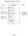
- FIG. 5is a block diagram of a control system in accordance with a second preferred embodiment of the present invention.
- FIG. 6is a block diagram of a pumping state detection module for use with the second embodiment
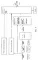
- FIG. 7is a flowchart for determining pump drive set point for the arrangement of the second embodiment
- FIG. 8illustrates graphically an HQ curve for a preferred pump type particularly suited for use with the control system of FIG. 2 or FIG. 5 ;
- FIG. 9is a diagram of a preferred embodiment of the present invention wherein said diagram shows preferred inputs and outputs.
- FIG. 1With initial reference to FIG. 1 there is illustrated in diagrammatic form a blood pump 10 installed within a human body 11 and arranged to function as a left ventricular assist device.
- the pump 10is arranged to operate in parallel with blood flow passing through left ventricle 12 . This is effected by inserting an inlet cannula 13 into left ventricle 12 and directing blood flow through the inlet cannula into an inlet of blood pump 10 .
- Blood pump 10in operational mode, pumps the blood thus received into aorta 14 via outlet cannula 15 , as illustrated in FIG. 1 .
- the blood pump 10can take a number of forms and rely on a number of different pumping and drive technologies.
- the pump technologycan be based on axial or centrifugal rotary pump arrangements or on positive displacement technologies.
- preferred pumping technologies for the control system to be described belowinclude rotary pump technologies which rely on an impeller supported for rotation within a casing and which causes blood to be urged between an inlet and outlet of the casing as the impeller rotates therein.
- a centrifugal form of pumpcan be utilised with the control system with the characteristics of the pump tailored to compliment or otherwise work particularly advantageously with the control system according to various embodiments of the present invention.
- the pump 10is driven by an electrical power source, in this instance a battery pack 16 mounted externally of the body. Electrical power from the battery pack 16 is controlled by a controller unit 17 , also mounted externally of the body. In addition to communicating electrical power to the pump 10 the controller 17 can also communicate with an external programming source, in this case a personal computer 18 for the purposes of initial setup and ongoing periodic monitoring and recalibration of the pump and controller as customised for a specific patient.
- an electrical power sourcein this instance a battery pack 16 mounted externally of the body.
- the controller 17can also communicate with an external programming source, in this case a personal computer 18 for the purposes of initial setup and ongoing periodic monitoring and recalibration of the pump and controller as customised for a specific patient.
- Embodiments of a control system suited for use, although not exclusively, with the controller 17 of the arrangement described above and with reference to FIG. 1will now be described.
- non-invasiveis applied to the derivation of various physiological parameters of body 11 (including blood flow rates and the like) by means which do not require sensors to be placed (invasively) within the body.
- IRBPimplantable rotary blood pump
- LVADleft ventricular assist device
- Vvoltage applied to pump motor
- TVCtotal ventricular collapse
- PVCpartial ventricular collapse
- the aimis to provide a pump controller which utilises a control algorithm which takes as its two primary inputs for decision making firstly an indication of the degree of movement of body 11 per unit time as a coarse measure of exertion and hence pumping load required of the heart and particularly left ventricle 12 and secondly an indication of heart rate derived, in this instance, non-invasively by monitoring of electrical parameters driving pump 10 .
- the block diagram shown in FIG. 2shows the signals that are derived (non-invasively) from pump motor power and speed.
- the strategyis to measure speed instantaneously every revolution of the impeller as a digital signal from the motor commutation electronics.
- the haemo-dynamic controller electronicsmeasure the frequency of this signal which is proportional to impeller speed.
- speedis an advantage since it is a digital signal, which in practice has been found to be an inherently less electrically noisy signal than that derived from measuring motor current or power.
- rmsroot mean square
- Each pulse from the commutation controllerrepresents 1 ⁇ 6 th of a rotation of the impeller and is time stamped relative to a reference time base. Therefore the angular velocity ⁇ of the impeller for each 60° of rotation is described by equation 1.
- ⁇ ⁇ ( T )2 ⁇ ⁇ ⁇ 6 ⁇ [ ( Tn + 1 ) - Tn ] equation ⁇ ⁇ 1
- Tn+1 ⁇ Tnis the time difference between pulses (interrupts) in seconds.
- ⁇ (t)is converted to speed N(t) in rpm by multiplying by 60/2 ⁇ as in equation 2
- N ⁇ ( t )60 ⁇ ⁇ ⁇ ( t ) 2 ⁇ ⁇ ⁇ equation ⁇ ⁇ 2
- Rms speedis calculated in equation 3 from a moving window of samples of N(t), the sample rate dependent on impeller speed. Each instantaneous speed sample is time stamped at t 1 to t n .
- Nrms ⁇ ( t )⁇ 0 n ⁇ ⁇ [ N ⁇ ( t ) ] 2 n equation ⁇ ⁇ 3 Calculation of Instantaneous and rms Electrical Input Power Pin(t).
- control strategyis similar to that described with respect to the first embodiment but, in addition, includes as a further control input derived from non-invasively determined parameters the “pumping state” of pump 10 .
- This featureprovides a safety-override mechanism as illustrated in the flowchart of FIG. 7 thereby to ensure that the basic control strategy described with reference to the first embodiment is less likely to put the patient at risk.
- FIG. 5is a block diagram of the control arrangement wherein, in addition to the input variables described with reference to example 1 there is a “physical motion” input which can be derived from an accelerometer associated with a patient.
- the accelerometercan be a single axis accelerometer. In alternative forms multiple axes of accelerometer sensing can be utilised.
- Physiologically critical pumping state detection methodsare used based on the non-invasive system observers pump speed and electrical input power. Activity level is detected using heart rate (detected from pump impeller instantaneous speed) and motion by using an accelerometer although other measuring devices may be used without departing from the scope of the present invention. These non-invasive observers are utilised as inputs to a control algorithm for a rotary blood pump to seek to ensure that pump output is better adapted to patient rest and exercise states.
- States PVC and PRcan be differentiated from state AC since flow pulsatility is more evident.
- State PVCcan be differentiated from state VE since the dynamic flow symmetry is different from all other states.
- the dynamic nature of the flowis reflected by pump speed and power. Instantaneous measured pump speed is used to indicate flow dynamics.
- the state PVCis indicated by a variation in symmetry of the instantaneous speed waveform given a level of pulsatility. Given that normal flow rates can still be observed during this state and that flow pulsatility is large, the only parameter distinguishing this state from the VE state is the flow symmetry.
- State VEmay be identified non invasively by pump flow rate being larger than 1 L/min and peak to peak instantaneous voltage (flow) being greater than a threshold value and the flow symmetry being greater than that for the PVC state.
- the PR statemay be indicated when the pump flow falls below the lower flow limits Qmin which is set to be 1 L/min. This level of Qmin is set at 1 L/min although not “0 L/min” may be was considered a safe limit to be classed as retrograde flow.
- Estimated pump flow Q estis derived from N rms (t) and PWR rms (t).
- the RMS of instantaneous pump speed N rms (t) and power PWR rms (t)are derived from instantaneous speed N(t) and power PWR(t).
- the haemo-dynamic controller electronicsmeasure the frequency of the speed signal, which is proportional to impeller speed. Using speed rather than power as an observer for dynamic changes is an advantage since it is a digital signal, substantially free from electrical noise which may contribute to error.
- Equation 6is used to model low and normal flow rate through the pump based on RMS impeller speed and electrical input power.
- Q est⁇ K+speed+Pwr+(Pwr) 2 +(Pwr) 3 equation 6
- a flow Index, Q p Index, shown in equation 7is developed to distinguish between low flow rates and normal flow rates by incorporating Q est . If Q p Index>50 this corresponds in this example to a flow rate greater than 1 L/min.
- States TVC and ACproduce near non pulsatile pump flow. The difference between these states is that state AC occurs when the circulation is supported and state TVC when it is not. These states can be differentiated by comparing Q est Index. States PVC, VE and PR produces pulsatile flow. States PVC and VE produce flow which supports the circulation whereas state PR compromises the circulation due to back flow through the pump. It has been shown that instantaneous speed amplitude is proportional to pump flow amplitude.
- the flow pulsatility index Q p ⁇ p Index(equation 9) is developed based on instantaneous speed amplitude N p-p (n) (equation 8) which is equal to the difference between the maximum and the minimum instantaneous impeller speed N max (n) and N min (n) for the n th cardiac cycle.
- the indexoutputs a value greater than 50 for pulsatile flow and less than 50 for non pulsatile flow.
- N p - p ⁇ ( n )N max ⁇ ( n ) - N min ⁇ ( n ) equation ⁇ ⁇ 8
- Q p - p ⁇ Index50 ⁇ Q p - p ⁇ min N p - p ⁇ ( n ) equation ⁇ ⁇ 9 Detecting Variations in Flow Symmetry
- States PVC and VEboth produce flow rates which support the circulation and a degree of pulsatility. Differentiating between states can be achieved by considering the symmetry of the flow wave form which is reflected in instantaneous speed.
- the symmetry of flow rateis an inversion of the instantaneous speed signal.
- the flow symmetry index Q sym Index(equation 11) is developed by using the inverted speed waveform symmetry defined by equation 10 with the symmetry threshold Q sym MAX set at 0. The index is set so that if the flow symmetry falls below 0.3 (speed symmetry rises above 0.7) its output is less than 50.
- N sym( N rms ⁇ ( n ) - N min ⁇ ( n ) N p - p ⁇ ( n ) equation ⁇ ⁇ 10
- Q sym ⁇ Index50 ⁇ Q sym ⁇ MAX N sym . equation ⁇ ⁇ 11 Determining the Current Pumping State from Non-Invasive Indicators
- the block diagram shown in FIG. 5shows the module that combines the detection methods discussed above derived from instantaneous power and speed.
- the current stateis determined by the logic table shown in FIG. 10 where flow, flow pulsatility and symmetry are used to decide the present pumping state.
- the heart rateis calculated by using the array of speed samples.
- the frequency of speedis calculated by using the derivative of speed and detecting the time of the speed maxima and minima.
- the derivative of speedis defined in equation 12.
- HRis then calculated by time stamping the maxima and minima of the speed signal given by HRa and HRb in is equations 13 and 14. The average is then computed and used as HR using equation 15. Speed maxima are detected by dN(t n )/dt changing from a positive to a negative value. Speed minima are detected by dN(t n )/dt changing from a negative to a positive value. T max(n) , t max(n ⁇ 1) , t min(n) , t min(n ⁇ 1) are the time stamps for the maximum and minimum values of instantaneous speed.
- An accelerometeris mounted in the controller electronics and used to detect physical motion.
- the accelerometer outputis amplified by a differential amplifier and integrated to provide a signal level indicating continuous physical motion.
- a preferred embodiment of the present invention of the physiological demand responsive controlleris suited for used with implantable third generation LVASs. Also, a further embodiment of the present invention is designed to cooperate with a VentrassistTM left ventricle assist system (LVAS).
- LVASVentrassistTM left ventricle assist system
- One of the preferred embodimentsmay automatically adjust the pumping speed of an implanted third generation blood pump to an optimal level for the varying physiological needs of the implanted patient.
- the preferred embodimentmay achieve this by periodically iteratively changing the speed setpoint of the pump.
- the control systemdetects increased physiological demand by the patient (e.g. by physical exertion) the controller will increase the pumping speed accordingly.
- the pumping state of the patient's heart and physiological demand of the patientwill be computed by the control system in real time as functions of the pump's motor power and speed setpoint of the pump.
- the physiological demand of the patientmay also be detected by the use of a three axis accelerometer.
- This accelerometermay be able to detect the instantaneous motion of the patient. Preferably, this instantaneous motion may also be indicative of the relative motion of the patient.
- the numerically represented version of the physiological demand statemay then be inputted into the control system for a pumping device or medical device.
- the pumping speed of the implantable blood pumpmay then be altered in respect of the predetermined range for physiological demand for a particular patient.
- the predetermined ranges of pumping speedswill be set by a specialist doctor at the time of implantation of the blood pump. Additionally, it may be preferable to allow doctors to amend the predetermined range as they see fit.
- control systemmay include a specialised algorithm.
- This algorithmmay include a mathematical model of ideal pumping speed of an implantable blood pump for suitable physiological conditions of the patient.
- This algorithmmay receive input or data included within three broad areas of data. These areas of data may include pump power, instantaneous pump speed and physical motion.
- the algorithm within the controller systemmay use these areas of data to predict certain patient data. This patient data may include blood flow rate, heart rate, flow profile, pulsatility and physiological demand.
- the algorithmwill then output the preferred pump speed and the remainder of the controller system will use this information to set a speed setpoint for the blood pump.
- an embodiment of the present inventionwill be such that iterative changes will be able to be made in timely manner.
- a preferred physiological demand responsive controller systemmay be adapted for use with a radial off flow type centrifugal blood pump.
- the systemis particularly suited for use with pumps which exhibit a relatively flat HQ curve as described with reference to FIG. 8 .
- pumps of the radial off flow typeas, for example, described in International Patent Application PCT/AU98/00725 can exhibit this relatively flat characteristic.
- the description of PCT/AU98/00725is incorporated herein by cross-reference.
Landscapes
- Health & Medical Sciences (AREA)
- Engineering & Computer Science (AREA)
- Heart & Thoracic Surgery (AREA)
- Cardiology (AREA)
- Biomedical Technology (AREA)
- Veterinary Medicine (AREA)
- Mechanical Engineering (AREA)
- Anesthesiology (AREA)
- Public Health (AREA)
- Hematology (AREA)
- Life Sciences & Earth Sciences (AREA)
- Animal Behavior & Ethology (AREA)
- General Health & Medical Sciences (AREA)
- Medical Informatics (AREA)
- Physics & Mathematics (AREA)
- Fluid Mechanics (AREA)
- Human Computer Interaction (AREA)
- External Artificial Organs (AREA)
Abstract
Description
- 1. Allowing motor speed to vary and deriving control information from those time varying signals; and
- 2. Concept of using control of power input or speed to the motor/pump.
where Tn+1−Tn is the time difference between pulses (interrupts) in seconds. ω(t) is converted to speed N(t) in rpm by multiplying by 60/2Π as in
Rms speed is calculated in
Calculation of Instantaneous and rms Electrical Input Power Pin(t).
Pin(t)=Vm(t)·Im(t) equation 4
Where Vm(t) and Im(t) are the “instantaneous” motor coil voltage and summed phase current respectively, sampled. A moving window of samples of Pin(t) is used to calculate Prms(t) using
| TABLE 1 |
| A summary of physiological (invasive) and pump (non-invasive) |
| parameters used as the criteria to identify pumping states. |
| Identifying Parameters |
| Non-invasive via pump (from | ||
| Invasion (Physiological) | speed and power) |
| AoP | Pulse Press. | LVP max | Qav | QestRMS(t) | Npp(n) | ||
| State | mmHg | (mmHg) | (mmHg) | (L/min) | (L/min) | Qsym(n) | (rpm) |
| TVC | <40 | <10 | <40 | <1 | <1 | — | <30 |
| PVC | 60-180 | >10 | 60-180 | <1 | >1 | <0.4 | >30 |
| AC | 60-180 | <10 | <AoP | <1 | >1 | — | <30 |
| VE | 60-180 | >10 | >AoP | >1 | >1 | >0.4 | >30 |
| PR | 60-180 | >10 | >AoP | >1 | <1 | >0.4 | >30 |
QestαK+speed+Pwr+(Pwr)2+(Pwr)3 equation 6
QpIndex=50·Qest equation 7
Detecting Variations in Flow Symmetry
Determining the Current Pumping State from Non-Invasive Indicators
Detection of Physical Motion
Claims (22)
Priority Applications (1)
| Application Number | Priority Date | Filing Date | Title |
|---|---|---|---|
| US13/172,748US20120004497A1 (en) | 2002-09-30 | 2011-06-29 | Physiological Demand Responsive Control System |
Applications Claiming Priority (3)
| Application Number | Priority Date | Filing Date | Title |
|---|---|---|---|
| AU2002951685 | 2002-09-30 | ||
| AU2002951685AAU2002951685A0 (en) | 2002-09-30 | 2002-09-30 | Physiological demand responsive control system |
| PCT/AU2003/001281WO2004028593A1 (en) | 2002-09-30 | 2003-09-30 | Physiological demand responsive control system |
Publications (2)
| Publication Number | Publication Date |
|---|---|
| US20080183287A1 US20080183287A1 (en) | 2008-07-31 |
| US7988728B2true US7988728B2 (en) | 2011-08-02 |
Family
ID=28047438
Family Applications (2)
| Application Number | Title | Priority Date | Filing Date |
|---|---|---|---|
| US10/529,657Active2026-09-24US7988728B2 (en) | 2002-09-30 | 2003-09-30 | Physiological demand responsive control system |
| US13/172,748AbandonedUS20120004497A1 (en) | 2002-09-30 | 2011-06-29 | Physiological Demand Responsive Control System |
Family Applications After (1)
| Application Number | Title | Priority Date | Filing Date |
|---|---|---|---|
| US13/172,748AbandonedUS20120004497A1 (en) | 2002-09-30 | 2011-06-29 | Physiological Demand Responsive Control System |
Country Status (6)
| Country | Link |
|---|---|
| US (2) | US7988728B2 (en) |
| EP (1) | EP1549363A4 (en) |
| JP (1) | JP2006500982A (en) |
| AU (1) | AU2002951685A0 (en) |
| CA (1) | CA2500554A1 (en) |
| WO (1) | WO2004028593A1 (en) |
Cited By (53)
| Publication number | Priority date | Publication date | Assignee | Title |
|---|---|---|---|---|
| US20100222846A1 (en)* | 2007-10-24 | 2010-09-02 | Medtronic, Inc. | Remotely- requested integrity diagnostics |
| US20130267764A1 (en)* | 2009-02-27 | 2013-10-10 | Victor Poirier | Blood flow meter |
| US8864643B2 (en) | 2011-10-13 | 2014-10-21 | Thoratec Corporation | Pump and method for mixed flow blood pumping |
| US8894561B2 (en) | 2012-03-05 | 2014-11-25 | Thoratec Corporation | Modular implantable medical pump |
| US9144638B2 (en) | 2013-03-14 | 2015-09-29 | Thoratec Corporation | Blood pump rotor bearings |
| US9265870B2 (en) | 2010-10-13 | 2016-02-23 | Thoratec Corporation | Pumping blood |
| US9302035B2 (en) | 2013-08-02 | 2016-04-05 | Circulite, Inc. | Implantable blood flow system with secure remote control |
| US9687596B2 (en) | 2009-02-27 | 2017-06-27 | Tci Llc | Prevention of aortic valve fusion |
| US9717832B2 (en) | 2015-01-06 | 2017-08-01 | HeartWave, Inc. | Axial flow rotor with downstream bearing wash flow |
| US9801988B2 (en) | 2010-09-24 | 2017-10-31 | Tc1 Llc | Generating artificial pulse |
| US10342905B2 (en) | 2012-09-13 | 2019-07-09 | Circulite, Inc. | Blood flow system with variable speed control |
| US10413649B2 (en) | 2014-10-01 | 2019-09-17 | Heartware, Inc. | Back up controller system with updating |
| US10660998B2 (en) | 2016-08-12 | 2020-05-26 | Tci Llc | Devices and methods for monitoring bearing and seal performance |
| US10722631B2 (en) | 2018-02-01 | 2020-07-28 | Shifamed Holdings, Llc | Intravascular blood pumps and methods of use and manufacture |
| US10724534B2 (en) | 2014-11-26 | 2020-07-28 | Tc1 Llc | Pump and method for mixed flow blood pumping |
| US10780209B2 (en) | 2017-03-29 | 2020-09-22 | Tc1 Llc | Adjusting pump protocol based on irregular heart rhythm |
| US10835654B2 (en) | 2017-03-29 | 2020-11-17 | Tc1 Llc | Pressure sensing ventricular assist devices and methods of use |
| US10857273B2 (en) | 2016-07-21 | 2020-12-08 | Tc1 Llc | Rotary seal for cantilevered rotor pump and methods for axial flow blood pumping |
| US10933181B2 (en) | 2017-03-31 | 2021-03-02 | CorWave SA | Implantable pump system having a rectangular membrane |
| US11065436B2 (en) | 2017-03-29 | 2021-07-20 | Tc1 Llc | Communication methods and architecture for heart treatment systems |
| US11097091B2 (en) | 2016-04-11 | 2021-08-24 | CorWave SA | Implantable pump system having a coaxial ventricular cannula |
| US11167123B2 (en) | 2018-03-19 | 2021-11-09 | Tc1 Llc | Coordinated ventricular assist and cardiac rhythm management devices and methods |
| US11185677B2 (en) | 2017-06-07 | 2021-11-30 | Shifamed Holdings, Llc | Intravascular fluid movement devices, systems, and methods of use |
| US11191946B2 (en) | 2020-03-06 | 2021-12-07 | CorWave SA | Implantable blood pumps comprising a linear bearing |
| US11241570B2 (en) | 2018-07-17 | 2022-02-08 | Tc1 Llc | Systems and methods for inertial sensing for VAD diagnostics and closed loop control |
| US11298522B2 (en) | 2016-04-11 | 2022-04-12 | CorWave SA | Implantable pump system having an undulating membrane |
| US11311714B2 (en)* | 2017-02-02 | 2022-04-26 | Xenios Ag | Arrangement with a blood pump, a control unit and a device for transmitting the measured values |
| US11446480B2 (en) | 2017-11-29 | 2022-09-20 | CorWave SA | Implantable pump system having an undulating membrane with improved hydraulic performance |
| US11511103B2 (en) | 2017-11-13 | 2022-11-29 | Shifamed Holdings, Llc | Intravascular fluid movement devices, systems, and methods of use |
| US11512689B2 (en) | 2017-11-10 | 2022-11-29 | CorWave SA | Undulating-membrane fluid circulator |
| US11517740B2 (en) | 2018-03-15 | 2022-12-06 | Tc1 Llc | Methods for controlling a left ventricular assist device |
| US11654275B2 (en) | 2019-07-22 | 2023-05-23 | Shifamed Holdings, Llc | Intravascular blood pumps with struts and methods of use and manufacture |
| US11724089B2 (en) | 2019-09-25 | 2023-08-15 | Shifamed Holdings, Llc | Intravascular blood pump systems and methods of use and control thereof |
| US11752324B2 (en) | 2013-06-27 | 2023-09-12 | Cardiaccs As | Monitoring of a cardiac assist device |
| US11964145B2 (en) | 2019-07-12 | 2024-04-23 | Shifamed Holdings, Llc | Intravascular blood pumps and methods of manufacture and use |
| US12017059B2 (en) | 2022-11-15 | 2024-06-25 | CorWave SA | Implantable heart pump systems including an improved apical connector and/or graft connector |
| US12102815B2 (en) | 2019-09-25 | 2024-10-01 | Shifamed Holdings, Llc | Catheter blood pumps and collapsible pump housings |
| US12121713B2 (en) | 2019-09-25 | 2024-10-22 | Shifamed Holdings, Llc | Catheter blood pumps and collapsible blood conduits |
| US12144976B2 (en) | 2018-06-21 | 2024-11-19 | Kardion Gmbh | Method and device for detecting a wear condition of a ventricular assist device and for operating same, and ventricular assist device |
| US12161857B2 (en) | 2018-07-31 | 2024-12-10 | Shifamed Holdings, Llc | Intravascular blood pumps and methods of use |
| US12178554B2 (en) | 2018-06-06 | 2024-12-31 | Kardion Gmbh | Systems and methods for determining a viscosity of a fluid |
| US12194287B2 (en) | 2018-05-30 | 2025-01-14 | Kardion Gmbh | Method of manufacturing electrical conductor tracks in a region of an intravascular blood pump |
| US12201821B2 (en) | 2018-06-06 | 2025-01-21 | Kardion Gmbh | Method for determining a flow rate of a fluid flowing through an implanted vascular support system, and implantable vascular support system |
| US12222267B2 (en) | 2018-06-06 | 2025-02-11 | Kardion Gmbh | Analysis device and method for analyzing a viscosity of a fluid |
| US12220570B2 (en) | 2018-10-05 | 2025-02-11 | Shifamed Holdings, Llc | Intravascular blood pumps and methods of use |
| US12251550B2 (en) | 2022-04-26 | 2025-03-18 | CorWave SA | Blood pumps having an encapsulated actuator |
| US12257427B2 (en) | 2022-11-15 | 2025-03-25 | CorWave SA | Implantable heart pump systems including an improved apical connector and/or graft connector |
| US12257424B2 (en) | 2018-06-06 | 2025-03-25 | Kardion Gmbh | Implantable ventricular assist system and method for operating same |
| US12310708B2 (en) | 2018-06-06 | 2025-05-27 | Kardion Gmbh | Systems and methods for determining a flow speed of a fluid flowing through a cardiac assist device |
| US12311160B2 (en) | 2018-06-06 | 2025-05-27 | Kardion Gmbh | Method and system for determining the speed of sound in a fluid in the region of a cardiac support system |
| US12324906B2 (en) | 2018-06-06 | 2025-06-10 | Kardion Gmbh | Systems and methods for determining a total blood volume flow in a cardiac support system and vascular support system |
| US12377256B2 (en) | 2018-06-06 | 2025-08-05 | Kardion Gmbh | Cardiac support system flow measurement using pressure sensors |
| US12409310B2 (en) | 2019-12-11 | 2025-09-09 | Shifamed Holdings, Llc | Descending aorta and vena cava blood pumps |
Families Citing this family (52)
| Publication number | Priority date | Publication date | Assignee | Title |
|---|---|---|---|---|
| US6889082B2 (en) | 1997-10-09 | 2005-05-03 | Orqis Medical Corporation | Implantable heart assist system and method of applying same |
| AUPP995999A0 (en) | 1999-04-23 | 1999-05-20 | University Of Technology, Sydney | Non-contact estimation and control system |
| AUPR514201A0 (en) | 2001-05-21 | 2001-06-14 | Ventrassist Pty Ltd | Staged implantation of ventricular assist devices |
| AU2003903726A0 (en)* | 2003-07-18 | 2003-07-31 | Ventracor Limited | A device for detecting heart pumping state |
| EP1670524A4 (en) | 2003-10-09 | 2012-12-26 | Thoratec Corp | Impeller |
| US20060083642A1 (en) | 2004-10-18 | 2006-04-20 | Cook Martin C | Rotor stability of a rotary pump |
| US8202217B2 (en)* | 2004-12-20 | 2012-06-19 | Ip Venture, Inc. | Healthcare base |
| US10130801B1 (en)* | 2005-02-07 | 2018-11-20 | Ipventure, Inc. | Electronic transdermal chemical delivery |
| US20070142923A1 (en) | 2005-11-04 | 2007-06-21 | Ayre Peter J | Control systems for rotary blood pumps |
| JP4621776B2 (en) | 2005-12-01 | 2011-01-26 | ミシガン クリティカル ケア コンサルタンツ,インコーポレイテッド | Pulsating rotary ventricular pump |
| US8112293B2 (en)* | 2006-03-24 | 2012-02-07 | Ipventure, Inc | Medical monitoring system |
| EP1847281A1 (en) | 2006-04-20 | 2007-10-24 | Ventrassist Pty Ltd | System and method of controlling a rotary blood pump |
| US7850594B2 (en) | 2006-05-09 | 2010-12-14 | Thoratec Corporation | Pulsatile control system for a rotary blood pump |
| US7963905B2 (en) | 2006-10-11 | 2011-06-21 | Thoratec Corporation | Control system for a blood pump |
| US20080133006A1 (en) | 2006-10-27 | 2008-06-05 | Ventrassist Pty Ltd | Blood Pump With An Ultrasonic Transducer |
| JP5266464B2 (en)* | 2007-05-10 | 2013-08-21 | ライニッシュ−ヴェストフェリッシェ・テクニッシェ・ホッホシューレ・アーヘン | Cardiac function change evaluation device |
| US10178965B2 (en)* | 2007-06-22 | 2019-01-15 | Ipventure, Inc. | Activity monitoring system for pregnant women |
| US9011334B2 (en)* | 2007-09-27 | 2015-04-21 | Baxter International Inc. | Access disconnect detection |
| ATE556729T1 (en) | 2008-08-05 | 2012-05-15 | Michigan Critical Care Consultants Inc | APPARATUS AND METHOD FOR MONITORING AND CONTROLLING EXTRACORPOREAL BLOOD FLOW RELATIVE TO A PATIENT'S FLUID STATUS |
| AU2009292201B2 (en)* | 2008-09-10 | 2015-04-16 | Heartware, Inc. | TET system for implanted medical device |
| EP2396549B1 (en)* | 2009-02-12 | 2019-10-23 | MC3, Inc. | Modular fluid pump with cartridge |
| CN102341600B (en) | 2009-03-06 | 2014-12-10 | 胸腔科技有限公司 | Centrifugal pump device |
| WO2011090927A1 (en)* | 2010-01-19 | 2011-07-28 | Heartware, Inc. | Physiologically responsive vad |
| JP5898190B2 (en) | 2010-06-22 | 2016-04-06 | ソラテック コーポレーション | Fluid delivery system and method for monitoring a fluid delivery system |
| CA2802215A1 (en) | 2010-06-22 | 2011-12-29 | Thoratec Corporation | Apparatus and method for modifying pressure-flow characteristics of a pump |
| JP5577506B2 (en) | 2010-09-14 | 2014-08-27 | ソーラテック コーポレイション | Centrifugal pump device |
| JP5852122B2 (en) | 2010-09-24 | 2016-02-03 | ソーラテック コーポレイション | Control of circulation assist device |
| EP2693609B1 (en) | 2011-03-28 | 2017-05-03 | Thoratec Corporation | Rotation and drive device and centrifugal pump device using same |
| US8897873B2 (en)* | 2011-06-27 | 2014-11-25 | Heartware, Inc. | Flow estimation in a blood pump |
| US8827889B2 (en) | 2012-05-21 | 2014-09-09 | University Of Washington Through Its Center For Commercialization | Method and system for powering implantable devices |
| US11621583B2 (en) | 2012-05-21 | 2023-04-04 | University Of Washington | Distributed control adaptive wireless power transfer system |
| US9371826B2 (en) | 2013-01-24 | 2016-06-21 | Thoratec Corporation | Impeller position compensation using field oriented control |
| US9556873B2 (en) | 2013-02-27 | 2017-01-31 | Tc1 Llc | Startup sequence for centrifugal pump with levitated impeller |
| US9919088B2 (en) | 2013-03-14 | 2018-03-20 | Yale University | Implantable heart pump controller |
| US9789236B2 (en) | 2013-03-14 | 2017-10-17 | Yale University | Implantable heart pump controller |
| US10052420B2 (en) | 2013-04-30 | 2018-08-21 | Tc1 Llc | Heart beat identification and pump speed synchronization |
| EP2865397A1 (en) | 2013-10-22 | 2015-04-29 | Berlin Heart GmbH | Method for operating a pump device and pump device |
| SE537628C2 (en) | 2013-11-08 | 2015-08-18 | Bonvisi Ab | Device for irrigation and insufflation with blood pressure dependent pressure control |
| US9623161B2 (en)* | 2014-08-26 | 2017-04-18 | Tc1 Llc | Blood pump and method of suction detection |
| EP3256183B1 (en) | 2015-02-11 | 2025-08-13 | Tc1 Llc | Heart beat identification and pump speed synchronization |
| EP3256185B1 (en) | 2015-02-12 | 2019-10-30 | Tc1 Llc | System and method for controlling the position of a levitated rotor |
| US10371152B2 (en) | 2015-02-12 | 2019-08-06 | Tc1 Llc | Alternating pump gaps |
| EP3256184B1 (en) | 2015-02-13 | 2020-04-08 | Tc1 Llc | Impeller suspension mechanism for heart pump |
| CN108025121B (en) | 2015-09-25 | 2021-03-12 | 心脏器械股份有限公司 | Blood pump for ischemia detection and treatment |
| US10117983B2 (en) | 2015-11-16 | 2018-11-06 | Tc1 Llc | Pressure/flow characteristic modification of a centrifugal pump in a ventricular assist device |
| WO2019016802A1 (en)* | 2017-07-17 | 2019-01-24 | Livemetric (Medical) S.A. | Method and system for ventricular assistive device adjustment using a wearable device |
| AU2019262094A1 (en)* | 2018-05-03 | 2020-11-19 | Northern Development AS | Implantable device and delivery method |
| CN108671296B (en)* | 2018-05-25 | 2021-04-16 | 中国计量大学 | A multi-level and multi-objective left ventricular auxiliary blood pump physiological control system |
| EP3581216A1 (en)* | 2018-06-11 | 2019-12-18 | Universität Zürich | Blood pump for mechanical circulatory support for fontan patients |
| US11931561B2 (en)* | 2020-05-26 | 2024-03-19 | Medtronic, Inc. | Body position and activity based flow control for ventricular assist device (VAD) with fully implantable controller |
| CN116803447B (en)* | 2023-08-04 | 2024-11-01 | 萱闱(北京)生物科技有限公司 | Model construction method, parameter configuration method and related device |
| CN116889684B (en)* | 2023-08-04 | 2024-01-26 | 萱闱(北京)生物科技有限公司 | Parameter configuration method and system of blood supply driving device and related device |
Citations (13)
| Publication number | Priority date | Publication date | Assignee | Title |
|---|---|---|---|---|
| US5289821A (en) | 1993-06-30 | 1994-03-01 | Swartz William M | Method of ultrasonic Doppler monitoring of blood flow in a blood vessel |
| US5888242A (en) | 1996-11-01 | 1999-03-30 | Nimbus, Inc. | Speed control system for implanted blood pumps |
| US6027498A (en) | 1994-03-15 | 2000-02-22 | University Of Manitoba | Control of life support systems |
| US6068588A (en)* | 1999-01-07 | 2000-05-30 | International Business Machines Corporation | Counterbalanced pump |
| US6071093A (en) | 1996-10-18 | 2000-06-06 | Abiomed, Inc. | Bearingless blood pump and electronic drive system |
| WO2001005023A1 (en) | 1999-07-08 | 2001-01-18 | Kriton Medical, Inc. | Method and apparatus for controlling brushless dc motors in implantable medical devices |
| US20010009645A1 (en) | 2000-01-26 | 2001-07-26 | Hiroyuki Noda | Magnetically driven axial-flow pump |
| US6277078B1 (en) | 1999-11-19 | 2001-08-21 | Remon Medical Technologies, Ltd. | System and method for monitoring a parameter associated with the performance of a heart |
| WO2001072352A2 (en) | 2000-03-27 | 2001-10-04 | The Cleveland Clinic Foundation | Chronic performance control system for rotodynamic blood pumps |
| US20020183628A1 (en) | 2001-06-05 | 2002-12-05 | Sanford Reich | Pressure sensing endograft |
| US6623420B2 (en) | 2001-08-16 | 2003-09-23 | Apex Medical, Inc. | Physiological heart pump control |
| EP1354606A1 (en) | 2002-04-19 | 2003-10-22 | Thoratec Corporation | Adaptive speed control for blood pump |
| US7494459B2 (en)* | 2003-06-26 | 2009-02-24 | Biophan Technologies, Inc. | Sensor-equipped and algorithm-controlled direct mechanical ventricular assist device |
Family Cites Families (3)
| Publication number | Priority date | Publication date | Assignee | Title |
|---|---|---|---|---|
| US5267940A (en)* | 1989-11-29 | 1993-12-07 | The Administrators Of The Tulane Educational Fund | Cardiovascular flow enhancer and method of operation |
| US5807234A (en)* | 1997-06-27 | 1998-09-15 | Pacesetter, Inc. | Myostimulator control using metabolic demand and muscle performance |
| US6572557B2 (en)* | 2000-05-09 | 2003-06-03 | Pacesetter, Inc. | System and method for monitoring progression of cardiac disease state using physiologic sensors |
- 2002
- 2002-09-30AUAU2002951685Apatent/AU2002951685A0/ennot_activeAbandoned
- 2003
- 2003-09-30JPJP2004538568Apatent/JP2006500982A/enactivePending
- 2003-09-30EPEP03798004Apatent/EP1549363A4/ennot_activeWithdrawn
- 2003-09-30WOPCT/AU2003/001281patent/WO2004028593A1/enactiveApplication Filing
- 2003-09-30CACA002500554Apatent/CA2500554A1/ennot_activeAbandoned
- 2003-09-30USUS10/529,657patent/US7988728B2/enactiveActive
- 2011
- 2011-06-29USUS13/172,748patent/US20120004497A1/ennot_activeAbandoned
Patent Citations (17)
| Publication number | Priority date | Publication date | Assignee | Title |
|---|---|---|---|---|
| US5289821A (en) | 1993-06-30 | 1994-03-01 | Swartz William M | Method of ultrasonic Doppler monitoring of blood flow in a blood vessel |
| US6027498A (en) | 1994-03-15 | 2000-02-22 | University Of Manitoba | Control of life support systems |
| US6071093A (en) | 1996-10-18 | 2000-06-06 | Abiomed, Inc. | Bearingless blood pump and electronic drive system |
| US5888242A (en) | 1996-11-01 | 1999-03-30 | Nimbus, Inc. | Speed control system for implanted blood pumps |
| US6066086A (en)* | 1996-11-01 | 2000-05-23 | Nimbus, Inc. | Speed control system for implanted blood pumps |
| US6068588A (en)* | 1999-01-07 | 2000-05-30 | International Business Machines Corporation | Counterbalanced pump |
| WO2001005023A1 (en) | 1999-07-08 | 2001-01-18 | Kriton Medical, Inc. | Method and apparatus for controlling brushless dc motors in implantable medical devices |
| US7138776B1 (en) | 1999-07-08 | 2006-11-21 | Heartware, Inc. | Method and apparatus for controlling brushless DC motors in implantable medical devices |
| US6277078B1 (en) | 1999-11-19 | 2001-08-21 | Remon Medical Technologies, Ltd. | System and method for monitoring a parameter associated with the performance of a heart |
| US20010009645A1 (en) | 2000-01-26 | 2001-07-26 | Hiroyuki Noda | Magnetically driven axial-flow pump |
| WO2001072352A2 (en) | 2000-03-27 | 2001-10-04 | The Cleveland Clinic Foundation | Chronic performance control system for rotodynamic blood pumps |
| US7645225B2 (en) | 2000-03-27 | 2010-01-12 | Alexander Medvedev | Chronic performance control system for rotodynamic blood pumps |
| US20020183628A1 (en) | 2001-06-05 | 2002-12-05 | Sanford Reich | Pressure sensing endograft |
| US6623420B2 (en) | 2001-08-16 | 2003-09-23 | Apex Medical, Inc. | Physiological heart pump control |
| EP1354606A1 (en) | 2002-04-19 | 2003-10-22 | Thoratec Corporation | Adaptive speed control for blood pump |
| US6991595B2 (en) | 2002-04-19 | 2006-01-31 | Thoratec Corporation | Adaptive speed control for blood pump |
| US7494459B2 (en)* | 2003-06-26 | 2009-02-24 | Biophan Technologies, Inc. | Sensor-equipped and algorithm-controlled direct mechanical ventricular assist device |
Non-Patent Citations (3)
| Title |
|---|
| International Search Report, dated Feb. 9, 2004. |
| Maeda, K. et al.; Asaio Transactions, "Predictive control by physical activity rate of a total artificial heart during exercise;" vol. 34, No. 3, Jul. 1988, Abstract. |
| Maeda, K. et al.; Asaio Transactions, "Predictive control by physical activity rate of a total artificial heart during exercise;" vol. 34, No. 3, Jul. 1988, pp. 480-484. |
Cited By (84)
| Publication number | Priority date | Publication date | Assignee | Title |
|---|---|---|---|---|
| US20100222846A1 (en)* | 2007-10-24 | 2010-09-02 | Medtronic, Inc. | Remotely- requested integrity diagnostics |
| US9633170B2 (en)* | 2007-10-24 | 2017-04-25 | Medtronic, Inc. | Remotely-requested integrity diagnostics |
| US9687596B2 (en) | 2009-02-27 | 2017-06-27 | Tci Llc | Prevention of aortic valve fusion |
| US12083330B2 (en) | 2009-02-27 | 2024-09-10 | Tc1 Llc | Prevention of aortic valve fusion |
| US8715151B2 (en)* | 2009-02-27 | 2014-05-06 | Thoratec Corporation | Blood flow meter |
| US11648386B2 (en) | 2009-02-27 | 2023-05-16 | Tc1 Llc | Prevention of aortic valve fusion |
| US10046098B2 (en) | 2009-02-27 | 2018-08-14 | Tc1 Llc | Prevention of aortic valve fusion |
| US10376622B2 (en) | 2009-02-27 | 2019-08-13 | Tc1 Llc | Prevention of aortic valve fusion |
| US20130267764A1 (en)* | 2009-02-27 | 2013-10-10 | Victor Poirier | Blood flow meter |
| US10881772B2 (en) | 2010-09-24 | 2021-01-05 | Tc1 Llc | Generating artificial pulse |
| US11944799B2 (en) | 2010-09-24 | 2024-04-02 | Tc1 Llc | Generating artificial pulse |
| US10086122B2 (en) | 2010-09-24 | 2018-10-02 | Tc1 Llc | Generating artificial pulse |
| US9801988B2 (en) | 2010-09-24 | 2017-10-31 | Tc1 Llc | Generating artificial pulse |
| US9265870B2 (en) | 2010-10-13 | 2016-02-23 | Thoratec Corporation | Pumping blood |
| US9533082B2 (en) | 2011-10-13 | 2017-01-03 | Thoratec Corporation | Pump and method for mixed flow blood pumping |
| US10279093B2 (en) | 2011-10-13 | 2019-05-07 | Tc1 Llc | Pump and method for mixed flow blood pumping |
| US8864643B2 (en) | 2011-10-13 | 2014-10-21 | Thoratec Corporation | Pump and method for mixed flow blood pumping |
| US9387285B2 (en) | 2012-03-05 | 2016-07-12 | Thoratec Corporation | Modular implantable medical pump |
| US9186447B2 (en) | 2012-03-05 | 2015-11-17 | Thoratec Corporation | Modular implantable medical pump |
| US8894561B2 (en) | 2012-03-05 | 2014-11-25 | Thoratec Corporation | Modular implantable medical pump |
| US10342905B2 (en) | 2012-09-13 | 2019-07-09 | Circulite, Inc. | Blood flow system with variable speed control |
| US9759222B2 (en) | 2013-03-14 | 2017-09-12 | Tc1 Llc | Blood pump rotor bearings |
| US9144638B2 (en) | 2013-03-14 | 2015-09-29 | Thoratec Corporation | Blood pump rotor bearings |
| US11752324B2 (en) | 2013-06-27 | 2023-09-12 | Cardiaccs As | Monitoring of a cardiac assist device |
| US9302035B2 (en) | 2013-08-02 | 2016-04-05 | Circulite, Inc. | Implantable blood flow system with secure remote control |
| US10413649B2 (en) | 2014-10-01 | 2019-09-17 | Heartware, Inc. | Back up controller system with updating |
| US10724534B2 (en) | 2014-11-26 | 2020-07-28 | Tc1 Llc | Pump and method for mixed flow blood pumping |
| US9717832B2 (en) | 2015-01-06 | 2017-08-01 | HeartWave, Inc. | Axial flow rotor with downstream bearing wash flow |
| US10765788B2 (en) | 2015-01-06 | 2020-09-08 | Heartware, Inc. | Axial flow rotor with downstream bearing wash flow |
| US10080826B2 (en) | 2015-01-06 | 2018-09-25 | Heartware, Inc. | Axial flow rotor with downstream bearing wash flow |
| US11097091B2 (en) | 2016-04-11 | 2021-08-24 | CorWave SA | Implantable pump system having a coaxial ventricular cannula |
| US12005245B2 (en) | 2016-04-11 | 2024-06-11 | CorWave SA | Implantable pump system having an undulating membrane |
| US11712554B2 (en) | 2016-04-11 | 2023-08-01 | CorWave SA | Implantable pump system having a coaxial ventricular cannula |
| US11298522B2 (en) | 2016-04-11 | 2022-04-12 | CorWave SA | Implantable pump system having an undulating membrane |
| US10857273B2 (en) | 2016-07-21 | 2020-12-08 | Tc1 Llc | Rotary seal for cantilevered rotor pump and methods for axial flow blood pumping |
| US11413443B2 (en) | 2016-07-21 | 2022-08-16 | Tc1 Llc | Rotary seal for cantilevered rotor pump and methods for axial flow blood pumping |
| US10660998B2 (en) | 2016-08-12 | 2020-05-26 | Tci Llc | Devices and methods for monitoring bearing and seal performance |
| EP3576805B1 (en)* | 2017-02-02 | 2023-11-15 | Xenios AG | Arrangement with a blood pump, a control unit and a device for transmitting the measured values |
| US11311714B2 (en)* | 2017-02-02 | 2022-04-26 | Xenios Ag | Arrangement with a blood pump, a control unit and a device for transmitting the measured values |
| US11478629B2 (en) | 2017-03-29 | 2022-10-25 | Tc1 Llc | Adjusting pump protocol based on irregular heart rhythm |
| US10780209B2 (en) | 2017-03-29 | 2020-09-22 | Tc1 Llc | Adjusting pump protocol based on irregular heart rhythm |
| US12383156B2 (en) | 2017-03-29 | 2025-08-12 | Tc1 Llc | Pressure sensing ventricular assist devices and methods of use |
| US11065436B2 (en) | 2017-03-29 | 2021-07-20 | Tc1 Llc | Communication methods and architecture for heart treatment systems |
| US10835654B2 (en) | 2017-03-29 | 2020-11-17 | Tc1 Llc | Pressure sensing ventricular assist devices and methods of use |
| US11779234B2 (en) | 2017-03-29 | 2023-10-10 | Tc1 Llc | Pressure sensing ventricular assist devices and methods of use |
| US12029535B2 (en) | 2017-03-29 | 2024-07-09 | Tc1 Llc | Communication methods and architecture for heart treatment systems |
| US11623077B2 (en) | 2017-03-31 | 2023-04-11 | CorWave SA | Implantable pump system having a rectangular membrane |
| US10933181B2 (en) | 2017-03-31 | 2021-03-02 | CorWave SA | Implantable pump system having a rectangular membrane |
| US11185677B2 (en) | 2017-06-07 | 2021-11-30 | Shifamed Holdings, Llc | Intravascular fluid movement devices, systems, and methods of use |
| US11717670B2 (en) | 2017-06-07 | 2023-08-08 | Shifamed Holdings, LLP | Intravascular fluid movement devices, systems, and methods of use |
| US11512689B2 (en) | 2017-11-10 | 2022-11-29 | CorWave SA | Undulating-membrane fluid circulator |
| US11511103B2 (en) | 2017-11-13 | 2022-11-29 | Shifamed Holdings, Llc | Intravascular fluid movement devices, systems, and methods of use |
| US12214182B2 (en) | 2017-11-29 | 2025-02-04 | CorWave SA | Implantable pump system having an undulating membrane with improved hydraulic performance |
| US11446480B2 (en) | 2017-11-29 | 2022-09-20 | CorWave SA | Implantable pump system having an undulating membrane with improved hydraulic performance |
| US12076545B2 (en) | 2018-02-01 | 2024-09-03 | Shifamed Holdings, Llc | Intravascular blood pumps and methods of use and manufacture |
| US10722631B2 (en) | 2018-02-01 | 2020-07-28 | Shifamed Holdings, Llc | Intravascular blood pumps and methods of use and manufacture |
| US11229784B2 (en) | 2018-02-01 | 2022-01-25 | Shifamed Holdings, Llc | Intravascular blood pumps and methods of use and manufacture |
| US12390170B2 (en) | 2018-03-15 | 2025-08-19 | Tc1 Llc | Methods and systems for controlling a left ventricular assist device |
| US11517740B2 (en) | 2018-03-15 | 2022-12-06 | Tc1 Llc | Methods for controlling a left ventricular assist device |
| US11167123B2 (en) | 2018-03-19 | 2021-11-09 | Tc1 Llc | Coordinated ventricular assist and cardiac rhythm management devices and methods |
| US12194287B2 (en) | 2018-05-30 | 2025-01-14 | Kardion Gmbh | Method of manufacturing electrical conductor tracks in a region of an intravascular blood pump |
| US12257424B2 (en) | 2018-06-06 | 2025-03-25 | Kardion Gmbh | Implantable ventricular assist system and method for operating same |
| US12310708B2 (en) | 2018-06-06 | 2025-05-27 | Kardion Gmbh | Systems and methods for determining a flow speed of a fluid flowing through a cardiac assist device |
| US12377256B2 (en) | 2018-06-06 | 2025-08-05 | Kardion Gmbh | Cardiac support system flow measurement using pressure sensors |
| US12324906B2 (en) | 2018-06-06 | 2025-06-10 | Kardion Gmbh | Systems and methods for determining a total blood volume flow in a cardiac support system and vascular support system |
| US12311160B2 (en) | 2018-06-06 | 2025-05-27 | Kardion Gmbh | Method and system for determining the speed of sound in a fluid in the region of a cardiac support system |
| US12222267B2 (en) | 2018-06-06 | 2025-02-11 | Kardion Gmbh | Analysis device and method for analyzing a viscosity of a fluid |
| US12201821B2 (en) | 2018-06-06 | 2025-01-21 | Kardion Gmbh | Method for determining a flow rate of a fluid flowing through an implanted vascular support system, and implantable vascular support system |
| US12178554B2 (en) | 2018-06-06 | 2024-12-31 | Kardion Gmbh | Systems and methods for determining a viscosity of a fluid |
| US12144976B2 (en) | 2018-06-21 | 2024-11-19 | Kardion Gmbh | Method and device for detecting a wear condition of a ventricular assist device and for operating same, and ventricular assist device |
| US11241570B2 (en) | 2018-07-17 | 2022-02-08 | Tc1 Llc | Systems and methods for inertial sensing for VAD diagnostics and closed loop control |
| US12064612B2 (en) | 2018-07-17 | 2024-08-20 | Tc1 Llc | Systems and methods for inertial sensing for VAD diagnostics and closed loop control |
| US12161857B2 (en) | 2018-07-31 | 2024-12-10 | Shifamed Holdings, Llc | Intravascular blood pumps and methods of use |
| US12220570B2 (en) | 2018-10-05 | 2025-02-11 | Shifamed Holdings, Llc | Intravascular blood pumps and methods of use |
| US11964145B2 (en) | 2019-07-12 | 2024-04-23 | Shifamed Holdings, Llc | Intravascular blood pumps and methods of manufacture and use |
| US11654275B2 (en) | 2019-07-22 | 2023-05-23 | Shifamed Holdings, Llc | Intravascular blood pumps with struts and methods of use and manufacture |
| US12121713B2 (en) | 2019-09-25 | 2024-10-22 | Shifamed Holdings, Llc | Catheter blood pumps and collapsible blood conduits |
| US11724089B2 (en) | 2019-09-25 | 2023-08-15 | Shifamed Holdings, Llc | Intravascular blood pump systems and methods of use and control thereof |
| US12102815B2 (en) | 2019-09-25 | 2024-10-01 | Shifamed Holdings, Llc | Catheter blood pumps and collapsible pump housings |
| US12409310B2 (en) | 2019-12-11 | 2025-09-09 | Shifamed Holdings, Llc | Descending aorta and vena cava blood pumps |
| US11191946B2 (en) | 2020-03-06 | 2021-12-07 | CorWave SA | Implantable blood pumps comprising a linear bearing |
| US12251550B2 (en) | 2022-04-26 | 2025-03-18 | CorWave SA | Blood pumps having an encapsulated actuator |
| US12017059B2 (en) | 2022-11-15 | 2024-06-25 | CorWave SA | Implantable heart pump systems including an improved apical connector and/or graft connector |
| US12257427B2 (en) | 2022-11-15 | 2025-03-25 | CorWave SA | Implantable heart pump systems including an improved apical connector and/or graft connector |
Also Published As
| Publication number | Publication date |
|---|---|
| US20120004497A1 (en) | 2012-01-05 |
| US20080183287A1 (en) | 2008-07-31 |
| WO2004028593A1 (en) | 2004-04-08 |
| AU2002951685A0 (en) | 2002-10-17 |
| CA2500554A1 (en) | 2004-04-08 |
| EP1549363A1 (en) | 2005-07-06 |
| EP1549363A4 (en) | 2012-02-01 |
| JP2006500982A (en) | 2006-01-12 |
Similar Documents
| Publication | Publication Date | Title |
|---|---|---|
| US7988728B2 (en) | Physiological demand responsive control system | |
| US10688232B2 (en) | Pump preload index/indicator | |
| US12083330B2 (en) | Prevention of aortic valve fusion | |
| US7645225B2 (en) | Chronic performance control system for rotodynamic blood pumps | |
| EP3668562B1 (en) | Blood pump | |
| US9039595B2 (en) | Control systems for rotary blood pumps | |
| EP3400035B1 (en) | Heart pump with impeller rotational speed control | |
| US6066086A (en) | Speed control system for implanted blood pumps | |
| EP1565231B1 (en) | Rotary blood pump diagnostics and cardiac output controller | |
| US8657875B2 (en) | Method and apparatus for pumping blood | |
| CA2753966A1 (en) | Blood pump system with controlled weaning | |
| AU2003265729B2 (en) | Physiological demand responsive control system | |
| AU2006235839B2 (en) | Improvements to Control Systems for Rotary Blood Pumps | |
| HK40026713B (en) | Blood pump | |
| HK40026713A (en) | Blood pump |
Legal Events
| Date | Code | Title | Description |
|---|---|---|---|
| AS | Assignment | Owner name:VENTRASSIST PTY LTD., AUSTRALIA Free format text:ASSIGNMENT OF ASSIGNORS INTEREST;ASSIGNOR:AYRE, PETER JOSEPH;REEL/FRAME:018410/0044 Effective date:20050503 | |
| AS | Assignment | Owner name:HEARTWARE, INC., FLORIDA Free format text:AGREEMENT CONTAINING CONVENANT NOT TO SUE;ASSIGNORS:UNIVERSITY OF SYDNEY, AUSTRALIA;VENTRASSIST PTY, LTD.;VENTRACOR, LTD.;REEL/FRAME:023456/0242 Effective date:20051109 Owner name:HEARTWARE, LTD., AUSTRALIA Free format text:AGREEMENT CONTAINING CONVENANT NOT TO SUE;ASSIGNORS:UNIVERSITY OF SYDNEY, AUSTRALIA;VENTRASSIST PTY, LTD.;VENTRACOR, LTD.;REEL/FRAME:023456/0242 Effective date:20051109 | |
| AS | Assignment | Owner name:THORATEC CORPORATION,CALIFORNIA Free format text:ASSIGNMENT OF ASSIGNORS INTEREST;ASSIGNOR:VENTRASSIST PTY LTD.;REEL/FRAME:024091/0386 Effective date:20100121 Owner name:THORATEC CORPORATION, CALIFORNIA Free format text:ASSIGNMENT OF ASSIGNORS INTEREST;ASSIGNOR:VENTRASSIST PTY LTD.;REEL/FRAME:024091/0386 Effective date:20100121 | |
| STCF | Information on status: patent grant | Free format text:PATENTED CASE | |
| FPAY | Fee payment | Year of fee payment:4 | |
| AS | Assignment | Owner name:TC1 LLC, MINNESOTA Free format text:CONFIRMATORY ASSIGNMENT;ASSIGNOR:THORATEC LLC;REEL/FRAME:045193/0930 Effective date:20180126 | |
| MAFP | Maintenance fee payment | Free format text:PAYMENT OF MAINTENANCE FEE, 8TH YEAR, LARGE ENTITY (ORIGINAL EVENT CODE: M1552); ENTITY STATUS OF PATENT OWNER: LARGE ENTITY Year of fee payment:8 | |
| AS | Assignment | Owner name:THORATEC LLC, CALIFORNIA Free format text:ENTITY CONVERSION;ASSIGNOR:THORATEC CORPORATION;REEL/FRAME:048613/0146 Effective date:20151112 | |
| MAFP | Maintenance fee payment | Free format text:PAYMENT OF MAINTENANCE FEE, 12TH YEAR, LARGE ENTITY (ORIGINAL EVENT CODE: M1553); ENTITY STATUS OF PATENT OWNER: LARGE ENTITY Year of fee payment:12 |