US7986411B2 - Imaging of a turbid medium - Google Patents
Imaging of a turbid mediumDownload PDFInfo
- Publication number
- US7986411B2 US7986411B2US12/518,891US51889107AUS7986411B2US 7986411 B2US7986411 B2US 7986411B2US 51889107 AUS51889107 AUS 51889107AUS 7986411 B2US7986411 B2US 7986411B2
- Authority
- US
- United States
- Prior art keywords
- radiation
- wavelength
- comparison
- component
- threshold
- Prior art date
- Legal status (The legal status is an assumption and is not a legal conclusion. Google has not performed a legal analysis and makes no representation as to the accuracy of the status listed.)
- Expired - Fee Related, expires
Links
Images

Classifications
- G—PHYSICS
- G01—MEASURING; TESTING
- G01N—INVESTIGATING OR ANALYSING MATERIALS BY DETERMINING THEIR CHEMICAL OR PHYSICAL PROPERTIES
- G01N21/00—Investigating or analysing materials by the use of optical means, i.e. using sub-millimetre waves, infrared, visible or ultraviolet light
- G01N21/17—Systems in which incident light is modified in accordance with the properties of the material investigated
- G01N21/47—Scattering, i.e. diffuse reflection
- G01N21/4795—Scattering, i.e. diffuse reflection spatially resolved investigating of object in scattering medium
- A—HUMAN NECESSITIES
- A61—MEDICAL OR VETERINARY SCIENCE; HYGIENE
- A61B—DIAGNOSIS; SURGERY; IDENTIFICATION
- A61B5/00—Measuring for diagnostic purposes; Identification of persons
- A61B5/0059—Measuring for diagnostic purposes; Identification of persons using light, e.g. diagnosis by transillumination, diascopy, fluorescence
- A61B5/0082—Measuring for diagnostic purposes; Identification of persons using light, e.g. diagnosis by transillumination, diascopy, fluorescence adapted for particular medical purposes
- A61B5/0091—Measuring for diagnostic purposes; Identification of persons using light, e.g. diagnosis by transillumination, diascopy, fluorescence adapted for particular medical purposes for mammography
- A—HUMAN NECESSITIES
- A61—MEDICAL OR VETERINARY SCIENCE; HYGIENE
- A61B—DIAGNOSIS; SURGERY; IDENTIFICATION
- A61B5/00—Measuring for diagnostic purposes; Identification of persons
- A61B5/43—Detecting, measuring or recording for evaluating the reproductive systems
- A61B5/4306—Detecting, measuring or recording for evaluating the reproductive systems for evaluating the female reproductive systems, e.g. gynaecological evaluations
- A61B5/4312—Breast evaluation or disorder diagnosis
Definitions
- the inventionrelates to an imaging system for imaging a turbid medium.
- An imaging systemis known from the U.S. Pat. No. 6,738,658 in the form of a medical optical imaging scanner.
- the known medical optical imaging scanneris notably arranged for breast imaging.
- An illumination sourceis positioned to direct light to the object to be imaged, i.e. the breast to be imaged.
- Light of different wavelength ranges emerging from the breastis simultaneously detected by respective groups of photodetectors.
- Optical filtersare disposed in front of one of the groups of photodetectors to restrict the wavelength of light reaching that group of photodetectors.
- Data from the filtered set of photodetectorsare used to reconstruct a fluorescence image of the breast. Fluorescence is introduced in the breast through the use of a contrast agent in the form of a fluorophore which is excited by the illumination source. Data from the unfiltered set of photodetectors are used to reconstruct an absorption image of the breast. The fluorescent and absorption images of the breast are automatically co-registered within the perimeter of the breast. Subsequently, the absorption data are subtracted from the fluorescent data to reconstruct images that contain information that is new in the images obtained after application of the contrast agent.
- An object of the inventionis to provide an imaging system for imaging a turbid medium to improve contrast in the image independently of the concentration of contrast agent.
- an imaging system for imaging a turbid mediumcomprising
- the radiation components of different wavelength rangesare distinguished.
- the imageis reconstructed on the basis of a comparison of these radiation components.
- An insight of the present inventionis that the comparison of these radiation components avoids that contrast inversion occurs in the image caused by self-absorption of radiation propagating through the turbid medium.
- Another insightis that these radiation components can be distinguished on the basis of their respective wavelength ranges.
- good contrast in the reconstructed imageis achieved when the comparison is relatively more beneficial to one of the wavelength ranges to the other ones over the relevant range of concentration of contrast agent. Accordingly, in the comparison competition among wavelength ranges is such that the intensity (or photon count) of that one wavelength range dominates so that any contrast in that one wavelength range does not suffer from contrast inversion.
- the respective radiation componentsconcern radiation that is propagated through the turbid medium and which have undergone predominantly strong or weak self-absorption, respectively e.g. by a fluorescent contrast agent.
- the respective radiation componentsconcern radiation that has undergone strong or weak self-absorption by the contrast agent from the radiation source that is transmitted through the turbid medium and radiation that is generated due to excitation of a fluorescent contrast agent by the illumination source, respectively.
- the comparison of the fluorescent radiation from the object to the radiation component transmitted through the turbid medium of the objectreduces the negative effect, notably inversion of contrast in the reconstructed image due to self-absorption of the fluorescent radiation.
- the respective radiation components having respective wavelength rangesthere are several alternatives to distinguish the respective radiation components having respective wavelength ranges.
- One optionis to employ optical filters, having respective pass-bands that correspond to the wavelength-ranges of the radiation components to be distinguished.
- Another optionis to employ a dielectric mirror having reflection and transmission in the respective wavelength-ranges.
- different sensitivity ranges for respective groups of detector elementsmay be employed so that respective detector groups detect mainly the respective radiation components.
- a spectrometer, a grating prism or an optical dispersion elementmay be employed to separate the respective different wavelength ranges.
- two radiation componentsare distinguished, i.e. the low-wavelength radiation components having wavelengths less than the ceiling wavelength and the high-wavelength radiation component having wavelengths above a threshold wavelength.
- the ceiling wavelength and the threshold wavelengthare equal.
- the high-wavelength radiation componentmainly concerns fluorescent radiation that is generated by excitation of a fluorescent contrast agent and subsequently propagates through the turbid medium. It is noted that since the main processes during propagation are scattering and absorption, which are not much dependent on the energy of the near-infrared radiation, the energy distribution of the (e.g. near infrared) radiation is not changed as it propagates through the tissue.
- the low-wavelength radiation componentconcerns mainly radiation from the illumination source that is transmitted through the turbid medium and is partly absorbed in the turbid medium.
- the low-wavelength radiation component and the high-wavelength componentfurther distinguish between the dominating of self-absorption and non-dominating of self-absorption of the fluorescent radiation.
- the comparison of the high-wavelength radiation component to the low-wavelength componenteffectively eliminates the effect of self-absorption in the turbid medium. Accordingly, the image that is reconstructed on the basis of the comparison has contrast that is an increasing function of the employed concentration of contrast agent.
- contrast inversionis avoided, low contrast is avoided due to compensation of fluorescence by auto-absorption.
- the diagnostic quality of the imageis improved in that details even at low contrast are not obscured by contrast inversion and remain well visible.
- the imaging systemis provided with the option to base the reconstruction on the total level of detected radiation, i.e. the sum of the levels of the two (or more) radiation components.
- This optionis notably activated when a low concentration of contrast agent is applied. At such low concentration of contrast agent self-absorption does not or only hardly occur so that contrast inversion is quite unlikely.
- the signal-to-noise ratio (SNR) of the total level of detected radiationis higher than the SNR of an individual radiation component.
- the imaging system of the inventionis in particular destined to image an object that is formed at least partly from a turbid medium through which the radiation propagates to a large extent by scattering. Inhomogeneities may be present in the turbid medium which influence the propagation of radiation.
- a particular exampleis biological tissue, such as a woman's breast.
- the imaging system of the inventionis notably employed to image a woman's breast to reveal the presence of inhomogeneities such as benign or malignant tumors.
- optical tomography of biological tissuesuch as a woman's breast near-infrared radiation is particularly suitable because biological tissue is reasonably low absorbing but quite highly scattering in the wavelength range of 400 nm to 1400 nm, in particular good results are obtained in the wavelength range between 600 nm and 950 nm.
- the intensities or the signal amplitudes of the radiation componentscan be measured.
- the inventionalso relates to an imaging method, in particular a digital optical tomography method.
- This optical imaging method of the inventionachieves that in imaging of a turbid medium contrast inversion at increasing concentration of contrast agent is avoided.
- the inventionfurther relates to a computer program.
- the computer program of the inventioncan be provided on a data carrier such as a CD-ROM disk, or the computer program of the invention can be downloaded from a data network such as the worldwide web.
- FIG. 1shows a schematic diagram of the system for imaging a turbid medium of the invention
- FIG. 2schematically shows further details of an example of the detector module of the imaging system of the invention.
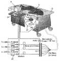
- FIG. 1shows a schematic diagram of the system for imaging a turbid medium of the invention.
- the imaging system of FIG. 1is a digital optical tomography system that is capable of producing an image of the interior of the object to be imaged.
- the system for imaging a turbid medium shown diagrammatically in FIG. 1is an optical mammography system.
- the optical mammography systemcomprises a carrier 11 , e.g. having the form of a patient bed or patient table, on which the patient to be examined (notably a woman whose breast(s) 1 are to be examined) is placed in prone position (i.e. face down) having one breast suspended in the examination space 2 that has the form of a measurement cup (not visible in FIG. 1 ).
- the measurement cupis further filled with a matching liquid that has optical scattering and absorption properties that closely resemble the optical scattering and absorption properties of the woman's breast.
- a large number of fibers 23(e.g. 510 in total) is connected with one end to the measurement cup.
- Half of the fibersare connected to detector modules 5 with an other end 3 , and half of the fibers are connected to a fiber-switch 12 through a further end.
- the fiber-switch 12can direct light from three different lasers 24 in either one of the 256 source fibers 23 (255 to the measurement cup, one directly to a detector fiber). In this way, either one of the source fibers 23 can provide a conical light beam in the measurement cup.
- all the source fiberswill emit a conical light beam into the breast tissue subsequently.
- the light from the selected source fiberis scattered by the matching fluid and the breast, and is detected by the 255 detector modules.
- a fluorescent contrast agentWhen a fluorescent contrast agent is employed the light from the source fiber excites the fluorescent contrast agent to emit fluorescent light at a (slightly) longer wavelength.
- the detector modulesare arranged to also detect the fluorescent and transmitted light from the patient to be examined, notably the woman's breast.
- the detector fibersare often arranged to arrive at detection position in respective rings around the wall of the measurement cup. The rings are displaced along the long axis (usually vertical) of the measurement cup.
- the attenuation of light in breast tissueis strong, which means that only a limited amount of photons can transverse the breast, compared to the reflected (or backscattered) light.
- Photodiodesare used as photosensors 5 in the detector modules.
- the front-end detector electronicsincludes one of these photodiodes and an amplifier.
- the amplification factor of the amplifiercan be switched between several values. The machine first measures at the lowest amplification, and increases the amplification if necessary.
- the detectorsare controlled by a computer 14 .
- the computer 14 including a display 9also controls the lasers, the fiber-switch, and the fluid dispensing system through connectors 4 .
- the computer, measurement cup, fibers, detectors, fiber-switch, and the lasersare all mounted into a bed as shown in FIG. 1 .
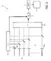
- FIG. 2schematically shows further details of an example of the detector module of the imaging system of the invention.
- the optical fibers 23are optically coupled to input channels at the input side of a detector module 8 .
- the detector module 8is provided with a separation module in the form of dielectric mirrors 120 for the respective input channels.
- Each of dielectric mirrorsis substantially reflective for the low-wavelength component and substantially transmitting for the high-wavelength component.
- These dielectric mirrorsare such as optical components commercially available. Light having a wavelength less than the threshold wavelength is reflected and light that has a wavelength larger than the threshold wavelength is transmitted.
- NIR96010SIDAG
- laser excitationmay be performed at a wavelength of 740 nm and fluorescence emission occurs in the range of wavelengths if 760 nm to 850 nm.
- Good resultsare obtained by setting the threshold and ceiling wavelength in the range between 780 nm and 790 nm.
- the reflected low-wavelength componentis reflected towards a high-energy detection sub-module 121 which includes photosensors that are sensitive for the low-wavelength component.
- the high-energy detection sub-module and the low-energy sub-moduleare equipped with the same or similar type photosensors having an intrinsic sensitivity range that covers both the high-wavelength and the low-wavelength ranges and to provide the high-energy and low-energy sub-module with different optical input filters.
- There optical input filtershave pass bands for the low-wavelength and high-wavelength ranges, respectively.
- the laser 23 to excite the contrast agent(aprrox. 690 nm for SIDAG) is filtered at pre-filters 122 . This pre-filtering avoids that the signal from the excitation laser 23 dominates the fluorescence signal.
- This pre-filter 122 in this examplefilters all wavelengths smaller than approx. 750 nm.
- the remaining spectrumis produced by the contrast agent, and this one again is split into lower and upper wavelength ranges to separate the self-absorption dominated ( ⁇ T ) from non-dominated region ( ⁇ > ⁇ T ), where ⁇ T is the threshold wavelength.
- the transmitted high-wavelength componentis transmitted to a low-energy detection sub-module 122 which includes photosensors that are sensitive for the high-wavelength component.
- the dielectric mirrorsare e.g. suitably coated to achieve the required wavelength reflection and transmission.
- the high-energy detection sub-moduleoutputs an electronic output signal that represents a spatially resolved distribution of the intensities of the low-wavelength radiation component from the object to be imaged.
- the low-energy detection sub-moduleoutputs an electronic output signal that represents a spatially resolved distribution of the intensities of the high-wavelength radiation component from the object to be imaged.
- the electric output signals of the respective detection sub-modulesare applied to the analysis module 6 which performs a comparison.
- the comparison between the low-wavelength component and the high-wavelength componentis e.g. simply performed by computing its ratio. It appears that notably this ratio is more in favor to the low-wavelength component over a wide range of concentrations of the fluorescent contrast agent.
- the comparison made by the analysis moduleis applied to the reconstruction module 7 .
- the analysis moduleprovides the ratio of the low-wavelength component to the high-wavelength component for a large number of respective pairs of source and detection positions. These individual detection positions are in fact the positions of the fiber tips of the detection fibers at the surface of the object to be imaged. These positions are relative to the object e.g. the woman's breast.
- the source positionis in fact the position (relative to the object) of the fiber that is selected to apply the laser light to the object, e.g. the woman's breast.
- the reconstruction modulereconstructs the image of the interior of the object to be imaged on the display 9 .
- This reconstructionnotably involves an algebraic reconstruction, a back-transformation or a Rytov approximation may be employed.
Landscapes
- Health & Medical Sciences (AREA)
- Life Sciences & Earth Sciences (AREA)
- Physics & Mathematics (AREA)
- General Health & Medical Sciences (AREA)
- Pathology (AREA)
- Biomedical Technology (AREA)
- Engineering & Computer Science (AREA)
- Heart & Thoracic Surgery (AREA)
- Medical Informatics (AREA)
- Molecular Biology (AREA)
- Surgery (AREA)
- Animal Behavior & Ethology (AREA)
- Biophysics (AREA)
- Public Health (AREA)
- Veterinary Medicine (AREA)
- Chemical & Material Sciences (AREA)
- Optics & Photonics (AREA)
- Analytical Chemistry (AREA)
- Biochemistry (AREA)
- General Physics & Mathematics (AREA)
- Immunology (AREA)
- Gynecology & Obstetrics (AREA)
- Reproductive Health (AREA)
- Investigating, Analyzing Materials By Fluorescence Or Luminescence (AREA)
- Investigating Or Analysing Materials By Optical Means (AREA)
- Apparatus For Radiation Diagnosis (AREA)
Abstract
Description
- a radiation source to illuminate an object to be imaged
- a detection system to detect radiation from the object and having a separation module which distinguishes radiation components having respective wavelength ranges
- an analysis module to form a comparison of respective radiation components and
- a reconstruction unit to access the comparison of respective radiation components and reconstruct an image dataset on the basis of the comparison of respective radiation components.
Claims (7)
Applications Claiming Priority (4)
| Application Number | Priority Date | Filing Date | Title |
|---|---|---|---|
| EP06126442 | 2006-12-19 | ||
| EP06126442 | 2006-12-19 | ||
| EP06126442.0 | 2006-12-19 | ||
| PCT/IB2007/055043WO2008075252A1 (en) | 2006-12-19 | 2007-12-12 | Imaging of a turbid medium |
Publications (2)
| Publication Number | Publication Date |
|---|---|
| US20100014084A1 US20100014084A1 (en) | 2010-01-21 |
| US7986411B2true US7986411B2 (en) | 2011-07-26 |
Family
ID=39247130
Family Applications (1)
| Application Number | Title | Priority Date | Filing Date |
|---|---|---|---|
| US12/518,891Expired - Fee RelatedUS7986411B2 (en) | 2006-12-19 | 2007-12-12 | Imaging of a turbid medium |
Country Status (5)
| Country | Link |
|---|---|
| US (1) | US7986411B2 (en) |
| EP (1) | EP2120687A1 (en) |
| JP (1) | JP2010512904A (en) |
| CN (1) | CN101563026B (en) |
| WO (1) | WO2008075252A1 (en) |
Cited By (2)
| Publication number | Priority date | Publication date | Assignee | Title |
|---|---|---|---|---|
| US20100002233A1 (en)* | 2006-10-30 | 2010-01-07 | Koninklijke Philips Electronics N.V. | Imaging of turbid medium |
| US9097647B2 (en) | 2012-08-08 | 2015-08-04 | Ut-Battelle, Llc | Method for using polarization gating to measure a scattering sample |
Families Citing this family (1)
| Publication number | Priority date | Publication date | Assignee | Title |
|---|---|---|---|---|
| US10195787B2 (en)* | 2016-05-12 | 2019-02-05 | Xerox Corporation | Electrostatic 3-D development apparatus using different melting point materials |
Citations (9)
| Publication number | Priority date | Publication date | Assignee | Title |
|---|---|---|---|---|
| US4945239A (en) | 1989-03-29 | 1990-07-31 | Center For Innovative Technology | Early detection of breast cancer using transillumination |
| WO1999001749A1 (en) | 1997-07-03 | 1999-01-14 | Smith & Nephew, Inc. | Fluorescence imaging system |
| US6175759B1 (en) | 1999-06-28 | 2001-01-16 | The United States Of America As Represented By The Secretary Of The Air Force | Contrast agent for multispectral infrared transillumination and fluorescence of turbid media |
| WO2001053802A2 (en) | 2000-01-21 | 2001-07-26 | Medical Optical Imaging, Inc. | Method and apparatus for detecting an abnormality within a host medium utilizing frequency-swept modulation diffusion tomography |
| US6280386B1 (en) | 1997-06-16 | 2001-08-28 | The Research Foundation Of The City University Of New York | Apparatus for enhancing the visibility of a luminous object inside tissue and methods for same |
| US20030135122A1 (en) | 1997-12-12 | 2003-07-17 | Spectrx, Inc. | Multi-modal optical tissue diagnostic system |
| US6687532B2 (en)* | 1997-12-12 | 2004-02-03 | Hamamatsu Photonics K.K. | Optical CT apparatus and image reconstructing method |
| US6738658B2 (en)* | 2000-05-09 | 2004-05-18 | Imaging Diagnostic Systems, Inc. | Medical optical imaging scanner using multiple wavelength simultaneous data acquisition for breast imaging |
| US20040245350A1 (en) | 2003-06-03 | 2004-12-09 | Haishan Zeng | Methods and apparatus for fluorescence imaging using multiple excitation-emission pairs and simultaneous multi-channel image detection |
Family Cites Families (13)
| Publication number | Priority date | Publication date | Assignee | Title |
|---|---|---|---|---|
| JPH0781948B2 (en)* | 1991-08-29 | 1995-09-06 | 工業技術院長 | Optical CT device |
| DE4318823C2 (en)* | 1993-06-07 | 2002-08-29 | Zeiss Carl | Device for scanning optical tissue examination |
| JP3310782B2 (en)* | 1994-07-14 | 2002-08-05 | 株式会社日立製作所 | Imaging device for spatial distribution of absorption substance concentration |
| JP2001510361A (en)* | 1996-12-03 | 2001-07-31 | コーニンクレッカ フィリップス エレクトロニクス エヌ ヴィ | Method and apparatus for imaging the interior of a turbid medium |
| JP3836941B2 (en)* | 1997-05-22 | 2006-10-25 | 浜松ホトニクス株式会社 | Optical CT apparatus and image reconstruction method |
| JPH11311569A (en)* | 1998-04-28 | 1999-11-09 | Hamamatsu Photonics Kk | Method and apparatus for measurement of distribution of internal characteristic |
| JP3887486B2 (en)* | 1998-05-26 | 2007-02-28 | 浜松ホトニクス株式会社 | Method and apparatus for measuring internal characteristic distribution of scattering medium |
| CA2384813C (en)* | 1999-09-14 | 2014-01-21 | Randall L. Barbour | Method and system for imaging the dynamics of scattering medium |
| EP1278454A2 (en)* | 2000-05-05 | 2003-01-29 | Massachusetts Institute Of Technology | Optical computed tomography in a turbid media |
| US6615063B1 (en)* | 2000-11-27 | 2003-09-02 | The General Hospital Corporation | Fluorescence-mediated molecular tomography |
| US7778693B2 (en)* | 2002-04-06 | 2010-08-17 | The United States Of America As Represented By The Department Of Health And Human Services | System and method for quantifying the dynamic response of a target system |
| AU2003220677A1 (en)* | 2002-04-06 | 2003-10-27 | Randall L Barbour | Modification of the normalized difference method for real-time optical tomography |
| CA2581400C (en) | 2004-09-24 | 2017-10-31 | Art, Advanced Research Technologies Inc. | Optical imaging method for tissue characterization |
- 2007
- 2007-12-12JPJP2009542294Apatent/JP2010512904A/enactivePending
- 2007-12-12CNCN2007800471671Apatent/CN101563026B/ennot_activeExpired - Fee Related
- 2007-12-12USUS12/518,891patent/US7986411B2/ennot_activeExpired - Fee Related
- 2007-12-12WOPCT/IB2007/055043patent/WO2008075252A1/enactiveApplication Filing
- 2007-12-12EPEP07849441Apatent/EP2120687A1/ennot_activeWithdrawn
Patent Citations (9)
| Publication number | Priority date | Publication date | Assignee | Title |
|---|---|---|---|---|
| US4945239A (en) | 1989-03-29 | 1990-07-31 | Center For Innovative Technology | Early detection of breast cancer using transillumination |
| US6280386B1 (en) | 1997-06-16 | 2001-08-28 | The Research Foundation Of The City University Of New York | Apparatus for enhancing the visibility of a luminous object inside tissue and methods for same |
| WO1999001749A1 (en) | 1997-07-03 | 1999-01-14 | Smith & Nephew, Inc. | Fluorescence imaging system |
| US20030135122A1 (en) | 1997-12-12 | 2003-07-17 | Spectrx, Inc. | Multi-modal optical tissue diagnostic system |
| US6687532B2 (en)* | 1997-12-12 | 2004-02-03 | Hamamatsu Photonics K.K. | Optical CT apparatus and image reconstructing method |
| US6175759B1 (en) | 1999-06-28 | 2001-01-16 | The United States Of America As Represented By The Secretary Of The Air Force | Contrast agent for multispectral infrared transillumination and fluorescence of turbid media |
| WO2001053802A2 (en) | 2000-01-21 | 2001-07-26 | Medical Optical Imaging, Inc. | Method and apparatus for detecting an abnormality within a host medium utilizing frequency-swept modulation diffusion tomography |
| US6738658B2 (en)* | 2000-05-09 | 2004-05-18 | Imaging Diagnostic Systems, Inc. | Medical optical imaging scanner using multiple wavelength simultaneous data acquisition for breast imaging |
| US20040245350A1 (en) | 2003-06-03 | 2004-12-09 | Haishan Zeng | Methods and apparatus for fluorescence imaging using multiple excitation-emission pairs and simultaneous multi-channel image detection |
Cited By (2)
| Publication number | Priority date | Publication date | Assignee | Title |
|---|---|---|---|---|
| US20100002233A1 (en)* | 2006-10-30 | 2010-01-07 | Koninklijke Philips Electronics N.V. | Imaging of turbid medium |
| US9097647B2 (en) | 2012-08-08 | 2015-08-04 | Ut-Battelle, Llc | Method for using polarization gating to measure a scattering sample |
Also Published As
| Publication number | Publication date |
|---|---|
| JP2010512904A (en) | 2010-04-30 |
| CN101563026B (en) | 2012-10-10 |
| EP2120687A1 (en) | 2009-11-25 |
| WO2008075252A1 (en) | 2008-06-26 |
| CN101563026A (en) | 2009-10-21 |
| US20100014084A1 (en) | 2010-01-21 |
Similar Documents
| Publication | Publication Date | Title |
|---|---|---|
| Fantini et al. | Frequency‐domain optical mammography: Edge effect corrections | |
| US5555885A (en) | Examination of breast tissue using time-resolved spectroscopy | |
| Eda et al. | Multichannel time-resolved optical tomographic imaging system | |
| RU2507503C2 (en) | Method and device to carry out optical research of turbid media content | |
| US6795195B1 (en) | System and method for tomographic imaging of dynamic properties of a scattering medium | |
| US7224468B2 (en) | En-face functional imaging using multiple wavelengths | |
| US7818154B2 (en) | Monte Carlo based model of fluorescence in turbid media and methods and systems for using same to determine intrinsic fluorescence of turbid media | |
| CN101606052A (en) | Apparatus and method for acquiring image data from turbid media | |
| El-Ghussein et al. | Hybrid photomultiplier tube and photodiode parallel detection array for wideband optical spectroscopy of the breast guided by magnetic resonance imaging | |
| US11977027B2 (en) | Device and method for determining the depth of a subsurface fluorescent object within an optically absorbing and scattering medium and for determining concentration of fluorophore of the object | |
| CN106092996B (en) | Cancer diagnosis system based on autofluorescence life | |
| WO2013073245A1 (en) | Biometric device, biometric method, program, and recording medium | |
| US7986411B2 (en) | Imaging of a turbid medium | |
| Maffeis et al. | In vivo test-driven upgrade of a time domain multi-wavelength optical mammograph | |
| US20100105022A1 (en) | Analyzing biological cell material based on different interactions between illumination light and cell components | |
| Qu et al. | Excitation-and-collection geometry insensitive fluorescence imaging of tissue-simulating turbid media | |
| US6678049B1 (en) | Optical detection system and method | |
| Spigulis et al. | Lasers for in-vivo skin diagnostics: some recent developments | |
| Popenda et al. | Fluorescence lifetime measurements with all-fiber optical setup for non-invasive in-vivo diagnostics | |
| Iftimia et al. | Development of a combined optical and fluorescence imaging system in frequency-domain for breast cancer detection | |
| Bakker et al. | Optical fluorescence imaging of breast cancer | |
| Belkov et al. | Optical biopsy system for breast cancer diagnostics | |
| Grosenick et al. | Phantom study on combined cw and time-domain fluorescence mammography | |
| WO2009060383A2 (en) | Method for calibrating a device for imaging the interior of turbid media and method for correcting measured intensities in such a device | |
| Chen et al. | Portable multichannel multiwavelength near-infrared diffusive light imager |
Legal Events
| Date | Code | Title | Description |
|---|---|---|---|
| AS | Assignment | Owner name:KONINKLIJKE PHILIPS ELECTRONICS N V,NETHERLANDS Free format text:ASSIGNMENT OF ASSIGNORS INTEREST;ASSIGNORS:ZIEGLER, RONNY;NIELSEN, TIM;REEL/FRAME:022817/0262 Effective date:20071221 Owner name:KONINKLIJKE PHILIPS ELECTRONICS N V, NETHERLANDS Free format text:ASSIGNMENT OF ASSIGNORS INTEREST;ASSIGNORS:ZIEGLER, RONNY;NIELSEN, TIM;REEL/FRAME:022817/0262 Effective date:20071221 | |
| STCF | Information on status: patent grant | Free format text:PATENTED CASE | |
| FPAY | Fee payment | Year of fee payment:4 | |
| SULP | Surcharge for late payment | ||
| MAFP | Maintenance fee payment | Free format text:PAYMENT OF MAINTENANCE FEE, 8TH YEAR, LARGE ENTITY (ORIGINAL EVENT CODE: M1552); ENTITY STATUS OF PATENT OWNER: LARGE ENTITY Year of fee payment:8 | |
| FEPP | Fee payment procedure | Free format text:MAINTENANCE FEE REMINDER MAILED (ORIGINAL EVENT CODE: REM.); ENTITY STATUS OF PATENT OWNER: LARGE ENTITY | |
| LAPS | Lapse for failure to pay maintenance fees | Free format text:PATENT EXPIRED FOR FAILURE TO PAY MAINTENANCE FEES (ORIGINAL EVENT CODE: EXP.); ENTITY STATUS OF PATENT OWNER: LARGE ENTITY | |
| STCH | Information on status: patent discontinuation | Free format text:PATENT EXPIRED DUE TO NONPAYMENT OF MAINTENANCE FEES UNDER 37 CFR 1.362 | |
| FP | Lapsed due to failure to pay maintenance fee | Effective date:20230726 |