US7985256B2 - Selectively expanding spine cage, hydraulically controllable in three dimensions for enhanced spinal fusion - Google Patents
Selectively expanding spine cage, hydraulically controllable in three dimensions for enhanced spinal fusionDownload PDFInfo
- Publication number
- US7985256B2 US7985256B2US11/535,432US53543206AUS7985256B2US 7985256 B2US7985256 B2US 7985256B2US 53543206 AUS53543206 AUS 53543206AUS 7985256 B2US7985256 B2US 7985256B2
- Authority
- US
- United States
- Prior art keywords
- implant
- pistons
- cylinders
- slave
- spinal
- Prior art date
- Legal status (The legal status is an assumption and is not a legal conclusion. Google has not performed a legal analysis and makes no representation as to the accuracy of the status listed.)
- Active, expires
Links
Images


Classifications
- A—HUMAN NECESSITIES
- A61—MEDICAL OR VETERINARY SCIENCE; HYGIENE
- A61F—FILTERS IMPLANTABLE INTO BLOOD VESSELS; PROSTHESES; DEVICES PROVIDING PATENCY TO, OR PREVENTING COLLAPSING OF, TUBULAR STRUCTURES OF THE BODY, e.g. STENTS; ORTHOPAEDIC, NURSING OR CONTRACEPTIVE DEVICES; FOMENTATION; TREATMENT OR PROTECTION OF EYES OR EARS; BANDAGES, DRESSINGS OR ABSORBENT PADS; FIRST-AID KITS
- A61F2/00—Filters implantable into blood vessels; Prostheses, i.e. artificial substitutes or replacements for parts of the body; Appliances for connecting them with the body; Devices providing patency to, or preventing collapsing of, tubular structures of the body, e.g. stents
- A61F2/02—Prostheses implantable into the body
- A61F2/30—Joints
- A61F2/46—Special tools for implanting artificial joints
- A61F2/4603—Special tools for implanting artificial joints for insertion or extraction of endoprosthetic joints or of accessories thereof
- A61F2/4611—Special tools for implanting artificial joints for insertion or extraction of endoprosthetic joints or of accessories thereof of spinal prostheses
- A—HUMAN NECESSITIES
- A61—MEDICAL OR VETERINARY SCIENCE; HYGIENE
- A61F—FILTERS IMPLANTABLE INTO BLOOD VESSELS; PROSTHESES; DEVICES PROVIDING PATENCY TO, OR PREVENTING COLLAPSING OF, TUBULAR STRUCTURES OF THE BODY, e.g. STENTS; ORTHOPAEDIC, NURSING OR CONTRACEPTIVE DEVICES; FOMENTATION; TREATMENT OR PROTECTION OF EYES OR EARS; BANDAGES, DRESSINGS OR ABSORBENT PADS; FIRST-AID KITS
- A61F2/00—Filters implantable into blood vessels; Prostheses, i.e. artificial substitutes or replacements for parts of the body; Appliances for connecting them with the body; Devices providing patency to, or preventing collapsing of, tubular structures of the body, e.g. stents
- A61F2/02—Prostheses implantable into the body
- A61F2/30—Joints
- A61F2/44—Joints for the spine, e.g. vertebrae, spinal discs
- A61F2/442—Intervertebral or spinal discs, e.g. resilient
- A—HUMAN NECESSITIES
- A61—MEDICAL OR VETERINARY SCIENCE; HYGIENE
- A61F—FILTERS IMPLANTABLE INTO BLOOD VESSELS; PROSTHESES; DEVICES PROVIDING PATENCY TO, OR PREVENTING COLLAPSING OF, TUBULAR STRUCTURES OF THE BODY, e.g. STENTS; ORTHOPAEDIC, NURSING OR CONTRACEPTIVE DEVICES; FOMENTATION; TREATMENT OR PROTECTION OF EYES OR EARS; BANDAGES, DRESSINGS OR ABSORBENT PADS; FIRST-AID KITS
- A61F2/00—Filters implantable into blood vessels; Prostheses, i.e. artificial substitutes or replacements for parts of the body; Appliances for connecting them with the body; Devices providing patency to, or preventing collapsing of, tubular structures of the body, e.g. stents
- A61F2/02—Prostheses implantable into the body
- A61F2/30—Joints
- A61F2/44—Joints for the spine, e.g. vertebrae, spinal discs
- A61F2/4455—Joints for the spine, e.g. vertebrae, spinal discs for the fusion of spinal bodies, e.g. intervertebral fusion of adjacent spinal bodies, e.g. fusion cages
- A61F2/4465—Joints for the spine, e.g. vertebrae, spinal discs for the fusion of spinal bodies, e.g. intervertebral fusion of adjacent spinal bodies, e.g. fusion cages having a circular or kidney shaped cross-section substantially perpendicular to the axis of the spine
- A—HUMAN NECESSITIES
- A61—MEDICAL OR VETERINARY SCIENCE; HYGIENE
- A61F—FILTERS IMPLANTABLE INTO BLOOD VESSELS; PROSTHESES; DEVICES PROVIDING PATENCY TO, OR PREVENTING COLLAPSING OF, TUBULAR STRUCTURES OF THE BODY, e.g. STENTS; ORTHOPAEDIC, NURSING OR CONTRACEPTIVE DEVICES; FOMENTATION; TREATMENT OR PROTECTION OF EYES OR EARS; BANDAGES, DRESSINGS OR ABSORBENT PADS; FIRST-AID KITS
- A61F2/00—Filters implantable into blood vessels; Prostheses, i.e. artificial substitutes or replacements for parts of the body; Appliances for connecting them with the body; Devices providing patency to, or preventing collapsing of, tubular structures of the body, e.g. stents
- A61F2/02—Prostheses implantable into the body
- A61F2/30—Joints
- A61F2/46—Special tools for implanting artificial joints
- A61F2/4601—Special tools for implanting artificial joints for introducing bone substitute, for implanting bone graft implants or for compacting them in the bone cavity
- A—HUMAN NECESSITIES
- A61—MEDICAL OR VETERINARY SCIENCE; HYGIENE
- A61F—FILTERS IMPLANTABLE INTO BLOOD VESSELS; PROSTHESES; DEVICES PROVIDING PATENCY TO, OR PREVENTING COLLAPSING OF, TUBULAR STRUCTURES OF THE BODY, e.g. STENTS; ORTHOPAEDIC, NURSING OR CONTRACEPTIVE DEVICES; FOMENTATION; TREATMENT OR PROTECTION OF EYES OR EARS; BANDAGES, DRESSINGS OR ABSORBENT PADS; FIRST-AID KITS
- A61F2/00—Filters implantable into blood vessels; Prostheses, i.e. artificial substitutes or replacements for parts of the body; Appliances for connecting them with the body; Devices providing patency to, or preventing collapsing of, tubular structures of the body, e.g. stents
- A61F2/02—Prostheses implantable into the body
- A61F2/30—Joints
- A61F2/30767—Special external or bone-contacting surface, e.g. coating for improving bone ingrowth
- A61F2/30771—Special external or bone-contacting surface, e.g. coating for improving bone ingrowth applied in original prostheses, e.g. holes or grooves
- A—HUMAN NECESSITIES
- A61—MEDICAL OR VETERINARY SCIENCE; HYGIENE
- A61F—FILTERS IMPLANTABLE INTO BLOOD VESSELS; PROSTHESES; DEVICES PROVIDING PATENCY TO, OR PREVENTING COLLAPSING OF, TUBULAR STRUCTURES OF THE BODY, e.g. STENTS; ORTHOPAEDIC, NURSING OR CONTRACEPTIVE DEVICES; FOMENTATION; TREATMENT OR PROTECTION OF EYES OR EARS; BANDAGES, DRESSINGS OR ABSORBENT PADS; FIRST-AID KITS
- A61F2/00—Filters implantable into blood vessels; Prostheses, i.e. artificial substitutes or replacements for parts of the body; Appliances for connecting them with the body; Devices providing patency to, or preventing collapsing of, tubular structures of the body, e.g. stents
- A61F2/02—Prostheses implantable into the body
- A61F2/48—Operating or control means, e.g. from outside the body, control of sphincters
- A61F2/484—Fluid means, i.e. hydraulic or pneumatic
- A—HUMAN NECESSITIES
- A61—MEDICAL OR VETERINARY SCIENCE; HYGIENE
- A61F—FILTERS IMPLANTABLE INTO BLOOD VESSELS; PROSTHESES; DEVICES PROVIDING PATENCY TO, OR PREVENTING COLLAPSING OF, TUBULAR STRUCTURES OF THE BODY, e.g. STENTS; ORTHOPAEDIC, NURSING OR CONTRACEPTIVE DEVICES; FOMENTATION; TREATMENT OR PROTECTION OF EYES OR EARS; BANDAGES, DRESSINGS OR ABSORBENT PADS; FIRST-AID KITS
- A61F2/00—Filters implantable into blood vessels; Prostheses, i.e. artificial substitutes or replacements for parts of the body; Appliances for connecting them with the body; Devices providing patency to, or preventing collapsing of, tubular structures of the body, e.g. stents
- A61F2/02—Prostheses implantable into the body
- A61F2/28—Bones
- A61F2002/2835—Bone graft implants for filling a bony defect or an endoprosthesis cavity, e.g. by synthetic material or biological material
- A—HUMAN NECESSITIES
- A61—MEDICAL OR VETERINARY SCIENCE; HYGIENE
- A61F—FILTERS IMPLANTABLE INTO BLOOD VESSELS; PROSTHESES; DEVICES PROVIDING PATENCY TO, OR PREVENTING COLLAPSING OF, TUBULAR STRUCTURES OF THE BODY, e.g. STENTS; ORTHOPAEDIC, NURSING OR CONTRACEPTIVE DEVICES; FOMENTATION; TREATMENT OR PROTECTION OF EYES OR EARS; BANDAGES, DRESSINGS OR ABSORBENT PADS; FIRST-AID KITS
- A61F2/00—Filters implantable into blood vessels; Prostheses, i.e. artificial substitutes or replacements for parts of the body; Appliances for connecting them with the body; Devices providing patency to, or preventing collapsing of, tubular structures of the body, e.g. stents
- A61F2/02—Prostheses implantable into the body
- A61F2/30—Joints
- A61F2002/30001—Additional features of subject-matter classified in A61F2/28, A61F2/30 and subgroups thereof
- A61F2002/30108—Shapes
- A61F2002/3011—Cross-sections or two-dimensional shapes
- A61F2002/30112—Rounded shapes, e.g. with rounded corners
- A61F2002/30133—Rounded shapes, e.g. with rounded corners kidney-shaped or bean-shaped
- A—HUMAN NECESSITIES
- A61—MEDICAL OR VETERINARY SCIENCE; HYGIENE
- A61F—FILTERS IMPLANTABLE INTO BLOOD VESSELS; PROSTHESES; DEVICES PROVIDING PATENCY TO, OR PREVENTING COLLAPSING OF, TUBULAR STRUCTURES OF THE BODY, e.g. STENTS; ORTHOPAEDIC, NURSING OR CONTRACEPTIVE DEVICES; FOMENTATION; TREATMENT OR PROTECTION OF EYES OR EARS; BANDAGES, DRESSINGS OR ABSORBENT PADS; FIRST-AID KITS
- A61F2/00—Filters implantable into blood vessels; Prostheses, i.e. artificial substitutes or replacements for parts of the body; Appliances for connecting them with the body; Devices providing patency to, or preventing collapsing of, tubular structures of the body, e.g. stents
- A61F2/02—Prostheses implantable into the body
- A61F2/30—Joints
- A61F2002/30001—Additional features of subject-matter classified in A61F2/28, A61F2/30 and subgroups thereof
- A61F2002/30108—Shapes
- A61F2002/30199—Three-dimensional shapes
- A61F2002/30224—Three-dimensional shapes cylindrical
- A61F2002/30235—Three-dimensional shapes cylindrical tubular, e.g. sleeves
- A—HUMAN NECESSITIES
- A61—MEDICAL OR VETERINARY SCIENCE; HYGIENE
- A61F—FILTERS IMPLANTABLE INTO BLOOD VESSELS; PROSTHESES; DEVICES PROVIDING PATENCY TO, OR PREVENTING COLLAPSING OF, TUBULAR STRUCTURES OF THE BODY, e.g. STENTS; ORTHOPAEDIC, NURSING OR CONTRACEPTIVE DEVICES; FOMENTATION; TREATMENT OR PROTECTION OF EYES OR EARS; BANDAGES, DRESSINGS OR ABSORBENT PADS; FIRST-AID KITS
- A61F2/00—Filters implantable into blood vessels; Prostheses, i.e. artificial substitutes or replacements for parts of the body; Appliances for connecting them with the body; Devices providing patency to, or preventing collapsing of, tubular structures of the body, e.g. stents
- A61F2/02—Prostheses implantable into the body
- A61F2/30—Joints
- A61F2002/30001—Additional features of subject-matter classified in A61F2/28, A61F2/30 and subgroups thereof
- A61F2002/30316—The prosthesis having different structural features at different locations within the same prosthesis; Connections between prosthetic parts; Special structural features of bone or joint prostheses not otherwise provided for
- A61F2002/30329—Connections or couplings between prosthetic parts, e.g. between modular parts; Connecting elements
- A61F2002/30433—Connections or couplings between prosthetic parts, e.g. between modular parts; Connecting elements using additional screws, bolts, dowels, rivets or washers e.g. connecting screws
- A—HUMAN NECESSITIES
- A61—MEDICAL OR VETERINARY SCIENCE; HYGIENE
- A61F—FILTERS IMPLANTABLE INTO BLOOD VESSELS; PROSTHESES; DEVICES PROVIDING PATENCY TO, OR PREVENTING COLLAPSING OF, TUBULAR STRUCTURES OF THE BODY, e.g. STENTS; ORTHOPAEDIC, NURSING OR CONTRACEPTIVE DEVICES; FOMENTATION; TREATMENT OR PROTECTION OF EYES OR EARS; BANDAGES, DRESSINGS OR ABSORBENT PADS; FIRST-AID KITS
- A61F2/00—Filters implantable into blood vessels; Prostheses, i.e. artificial substitutes or replacements for parts of the body; Appliances for connecting them with the body; Devices providing patency to, or preventing collapsing of, tubular structures of the body, e.g. stents
- A61F2/02—Prostheses implantable into the body
- A61F2/30—Joints
- A61F2002/30001—Additional features of subject-matter classified in A61F2/28, A61F2/30 and subgroups thereof
- A61F2002/30316—The prosthesis having different structural features at different locations within the same prosthesis; Connections between prosthetic parts; Special structural features of bone or joint prostheses not otherwise provided for
- A61F2002/30535—Special structural features of bone or joint prostheses not otherwise provided for
- A61F2002/30537—Special structural features of bone or joint prostheses not otherwise provided for adjustable
- A61F2002/30538—Special structural features of bone or joint prostheses not otherwise provided for adjustable for adjusting angular orientation
- A—HUMAN NECESSITIES
- A61—MEDICAL OR VETERINARY SCIENCE; HYGIENE
- A61F—FILTERS IMPLANTABLE INTO BLOOD VESSELS; PROSTHESES; DEVICES PROVIDING PATENCY TO, OR PREVENTING COLLAPSING OF, TUBULAR STRUCTURES OF THE BODY, e.g. STENTS; ORTHOPAEDIC, NURSING OR CONTRACEPTIVE DEVICES; FOMENTATION; TREATMENT OR PROTECTION OF EYES OR EARS; BANDAGES, DRESSINGS OR ABSORBENT PADS; FIRST-AID KITS
- A61F2/00—Filters implantable into blood vessels; Prostheses, i.e. artificial substitutes or replacements for parts of the body; Appliances for connecting them with the body; Devices providing patency to, or preventing collapsing of, tubular structures of the body, e.g. stents
- A61F2/02—Prostheses implantable into the body
- A61F2/30—Joints
- A61F2002/30001—Additional features of subject-matter classified in A61F2/28, A61F2/30 and subgroups thereof
- A61F2002/30316—The prosthesis having different structural features at different locations within the same prosthesis; Connections between prosthetic parts; Special structural features of bone or joint prostheses not otherwise provided for
- A61F2002/30535—Special structural features of bone or joint prostheses not otherwise provided for
- A61F2002/30537—Special structural features of bone or joint prostheses not otherwise provided for adjustable
- A61F2002/3055—Special structural features of bone or joint prostheses not otherwise provided for adjustable for adjusting length
- A—HUMAN NECESSITIES
- A61—MEDICAL OR VETERINARY SCIENCE; HYGIENE
- A61F—FILTERS IMPLANTABLE INTO BLOOD VESSELS; PROSTHESES; DEVICES PROVIDING PATENCY TO, OR PREVENTING COLLAPSING OF, TUBULAR STRUCTURES OF THE BODY, e.g. STENTS; ORTHOPAEDIC, NURSING OR CONTRACEPTIVE DEVICES; FOMENTATION; TREATMENT OR PROTECTION OF EYES OR EARS; BANDAGES, DRESSINGS OR ABSORBENT PADS; FIRST-AID KITS
- A61F2/00—Filters implantable into blood vessels; Prostheses, i.e. artificial substitutes or replacements for parts of the body; Appliances for connecting them with the body; Devices providing patency to, or preventing collapsing of, tubular structures of the body, e.g. stents
- A61F2/02—Prostheses implantable into the body
- A61F2/30—Joints
- A61F2002/30001—Additional features of subject-matter classified in A61F2/28, A61F2/30 and subgroups thereof
- A61F2002/30316—The prosthesis having different structural features at different locations within the same prosthesis; Connections between prosthetic parts; Special structural features of bone or joint prostheses not otherwise provided for
- A61F2002/30535—Special structural features of bone or joint prostheses not otherwise provided for
- A61F2002/30563—Special structural features of bone or joint prostheses not otherwise provided for having elastic means or damping means, different from springs, e.g. including an elastomeric core or shock absorbers
- A—HUMAN NECESSITIES
- A61—MEDICAL OR VETERINARY SCIENCE; HYGIENE
- A61F—FILTERS IMPLANTABLE INTO BLOOD VESSELS; PROSTHESES; DEVICES PROVIDING PATENCY TO, OR PREVENTING COLLAPSING OF, TUBULAR STRUCTURES OF THE BODY, e.g. STENTS; ORTHOPAEDIC, NURSING OR CONTRACEPTIVE DEVICES; FOMENTATION; TREATMENT OR PROTECTION OF EYES OR EARS; BANDAGES, DRESSINGS OR ABSORBENT PADS; FIRST-AID KITS
- A61F2/00—Filters implantable into blood vessels; Prostheses, i.e. artificial substitutes or replacements for parts of the body; Appliances for connecting them with the body; Devices providing patency to, or preventing collapsing of, tubular structures of the body, e.g. stents
- A61F2/02—Prostheses implantable into the body
- A61F2/30—Joints
- A61F2002/30001—Additional features of subject-matter classified in A61F2/28, A61F2/30 and subgroups thereof
- A61F2002/30316—The prosthesis having different structural features at different locations within the same prosthesis; Connections between prosthetic parts; Special structural features of bone or joint prostheses not otherwise provided for
- A61F2002/30535—Special structural features of bone or joint prostheses not otherwise provided for
- A61F2002/30579—Special structural features of bone or joint prostheses not otherwise provided for with mechanically expandable devices, e.g. fixation devices
- A—HUMAN NECESSITIES
- A61—MEDICAL OR VETERINARY SCIENCE; HYGIENE
- A61F—FILTERS IMPLANTABLE INTO BLOOD VESSELS; PROSTHESES; DEVICES PROVIDING PATENCY TO, OR PREVENTING COLLAPSING OF, TUBULAR STRUCTURES OF THE BODY, e.g. STENTS; ORTHOPAEDIC, NURSING OR CONTRACEPTIVE DEVICES; FOMENTATION; TREATMENT OR PROTECTION OF EYES OR EARS; BANDAGES, DRESSINGS OR ABSORBENT PADS; FIRST-AID KITS
- A61F2/00—Filters implantable into blood vessels; Prostheses, i.e. artificial substitutes or replacements for parts of the body; Appliances for connecting them with the body; Devices providing patency to, or preventing collapsing of, tubular structures of the body, e.g. stents
- A61F2/02—Prostheses implantable into the body
- A61F2/30—Joints
- A61F2002/30001—Additional features of subject-matter classified in A61F2/28, A61F2/30 and subgroups thereof
- A61F2002/30316—The prosthesis having different structural features at different locations within the same prosthesis; Connections between prosthetic parts; Special structural features of bone or joint prostheses not otherwise provided for
- A61F2002/30535—Special structural features of bone or joint prostheses not otherwise provided for
- A61F2002/30581—Special structural features of bone or joint prostheses not otherwise provided for having a pocket filled with fluid, e.g. liquid
- A61F2002/30583—Special structural features of bone or joint prostheses not otherwise provided for having a pocket filled with fluid, e.g. liquid filled with hardenable fluid, e.g. curable in-situ
- A—HUMAN NECESSITIES
- A61—MEDICAL OR VETERINARY SCIENCE; HYGIENE
- A61F—FILTERS IMPLANTABLE INTO BLOOD VESSELS; PROSTHESES; DEVICES PROVIDING PATENCY TO, OR PREVENTING COLLAPSING OF, TUBULAR STRUCTURES OF THE BODY, e.g. STENTS; ORTHOPAEDIC, NURSING OR CONTRACEPTIVE DEVICES; FOMENTATION; TREATMENT OR PROTECTION OF EYES OR EARS; BANDAGES, DRESSINGS OR ABSORBENT PADS; FIRST-AID KITS
- A61F2/00—Filters implantable into blood vessels; Prostheses, i.e. artificial substitutes or replacements for parts of the body; Appliances for connecting them with the body; Devices providing patency to, or preventing collapsing of, tubular structures of the body, e.g. stents
- A61F2/02—Prostheses implantable into the body
- A61F2/30—Joints
- A61F2002/30001—Additional features of subject-matter classified in A61F2/28, A61F2/30 and subgroups thereof
- A61F2002/30316—The prosthesis having different structural features at different locations within the same prosthesis; Connections between prosthetic parts; Special structural features of bone or joint prostheses not otherwise provided for
- A61F2002/30535—Special structural features of bone or joint prostheses not otherwise provided for
- A61F2002/30589—Sealing means
- A—HUMAN NECESSITIES
- A61—MEDICAL OR VETERINARY SCIENCE; HYGIENE
- A61F—FILTERS IMPLANTABLE INTO BLOOD VESSELS; PROSTHESES; DEVICES PROVIDING PATENCY TO, OR PREVENTING COLLAPSING OF, TUBULAR STRUCTURES OF THE BODY, e.g. STENTS; ORTHOPAEDIC, NURSING OR CONTRACEPTIVE DEVICES; FOMENTATION; TREATMENT OR PROTECTION OF EYES OR EARS; BANDAGES, DRESSINGS OR ABSORBENT PADS; FIRST-AID KITS
- A61F2/00—Filters implantable into blood vessels; Prostheses, i.e. artificial substitutes or replacements for parts of the body; Appliances for connecting them with the body; Devices providing patency to, or preventing collapsing of, tubular structures of the body, e.g. stents
- A61F2/02—Prostheses implantable into the body
- A61F2/30—Joints
- A61F2002/30001—Additional features of subject-matter classified in A61F2/28, A61F2/30 and subgroups thereof
- A61F2002/30316—The prosthesis having different structural features at different locations within the same prosthesis; Connections between prosthetic parts; Special structural features of bone or joint prostheses not otherwise provided for
- A61F2002/30535—Special structural features of bone or joint prostheses not otherwise provided for
- A61F2002/30593—Special structural features of bone or joint prostheses not otherwise provided for hollow
- A—HUMAN NECESSITIES
- A61—MEDICAL OR VETERINARY SCIENCE; HYGIENE
- A61F—FILTERS IMPLANTABLE INTO BLOOD VESSELS; PROSTHESES; DEVICES PROVIDING PATENCY TO, OR PREVENTING COLLAPSING OF, TUBULAR STRUCTURES OF THE BODY, e.g. STENTS; ORTHOPAEDIC, NURSING OR CONTRACEPTIVE DEVICES; FOMENTATION; TREATMENT OR PROTECTION OF EYES OR EARS; BANDAGES, DRESSINGS OR ABSORBENT PADS; FIRST-AID KITS
- A61F2/00—Filters implantable into blood vessels; Prostheses, i.e. artificial substitutes or replacements for parts of the body; Appliances for connecting them with the body; Devices providing patency to, or preventing collapsing of, tubular structures of the body, e.g. stents
- A61F2/02—Prostheses implantable into the body
- A61F2/30—Joints
- A61F2002/30001—Additional features of subject-matter classified in A61F2/28, A61F2/30 and subgroups thereof
- A61F2002/30316—The prosthesis having different structural features at different locations within the same prosthesis; Connections between prosthetic parts; Special structural features of bone or joint prostheses not otherwise provided for
- A61F2002/30535—Special structural features of bone or joint prostheses not otherwise provided for
- A61F2002/30604—Special structural features of bone or joint prostheses not otherwise provided for modular
- A—HUMAN NECESSITIES
- A61—MEDICAL OR VETERINARY SCIENCE; HYGIENE
- A61F—FILTERS IMPLANTABLE INTO BLOOD VESSELS; PROSTHESES; DEVICES PROVIDING PATENCY TO, OR PREVENTING COLLAPSING OF, TUBULAR STRUCTURES OF THE BODY, e.g. STENTS; ORTHOPAEDIC, NURSING OR CONTRACEPTIVE DEVICES; FOMENTATION; TREATMENT OR PROTECTION OF EYES OR EARS; BANDAGES, DRESSINGS OR ABSORBENT PADS; FIRST-AID KITS
- A61F2/00—Filters implantable into blood vessels; Prostheses, i.e. artificial substitutes or replacements for parts of the body; Appliances for connecting them with the body; Devices providing patency to, or preventing collapsing of, tubular structures of the body, e.g. stents
- A61F2/02—Prostheses implantable into the body
- A61F2/30—Joints
- A61F2002/30001—Additional features of subject-matter classified in A61F2/28, A61F2/30 and subgroups thereof
- A61F2002/30316—The prosthesis having different structural features at different locations within the same prosthesis; Connections between prosthetic parts; Special structural features of bone or joint prostheses not otherwise provided for
- A61F2002/30535—Special structural features of bone or joint prostheses not otherwise provided for
- A61F2002/30617—Visible markings for adjusting, locating or measuring
- A—HUMAN NECESSITIES
- A61—MEDICAL OR VETERINARY SCIENCE; HYGIENE
- A61F—FILTERS IMPLANTABLE INTO BLOOD VESSELS; PROSTHESES; DEVICES PROVIDING PATENCY TO, OR PREVENTING COLLAPSING OF, TUBULAR STRUCTURES OF THE BODY, e.g. STENTS; ORTHOPAEDIC, NURSING OR CONTRACEPTIVE DEVICES; FOMENTATION; TREATMENT OR PROTECTION OF EYES OR EARS; BANDAGES, DRESSINGS OR ABSORBENT PADS; FIRST-AID KITS
- A61F2/00—Filters implantable into blood vessels; Prostheses, i.e. artificial substitutes or replacements for parts of the body; Appliances for connecting them with the body; Devices providing patency to, or preventing collapsing of, tubular structures of the body, e.g. stents
- A61F2/02—Prostheses implantable into the body
- A61F2/30—Joints
- A61F2/30767—Special external or bone-contacting surface, e.g. coating for improving bone ingrowth
- A61F2/30771—Special external or bone-contacting surface, e.g. coating for improving bone ingrowth applied in original prostheses, e.g. holes or grooves
- A61F2002/30772—Apertures or holes, e.g. of circular cross section
- A—HUMAN NECESSITIES
- A61—MEDICAL OR VETERINARY SCIENCE; HYGIENE
- A61F—FILTERS IMPLANTABLE INTO BLOOD VESSELS; PROSTHESES; DEVICES PROVIDING PATENCY TO, OR PREVENTING COLLAPSING OF, TUBULAR STRUCTURES OF THE BODY, e.g. STENTS; ORTHOPAEDIC, NURSING OR CONTRACEPTIVE DEVICES; FOMENTATION; TREATMENT OR PROTECTION OF EYES OR EARS; BANDAGES, DRESSINGS OR ABSORBENT PADS; FIRST-AID KITS
- A61F2/00—Filters implantable into blood vessels; Prostheses, i.e. artificial substitutes or replacements for parts of the body; Appliances for connecting them with the body; Devices providing patency to, or preventing collapsing of, tubular structures of the body, e.g. stents
- A61F2/02—Prostheses implantable into the body
- A61F2/30—Joints
- A61F2/46—Special tools for implanting artificial joints
- A61F2/4603—Special tools for implanting artificial joints for insertion or extraction of endoprosthetic joints or of accessories thereof
- A61F2002/4625—Special tools for implanting artificial joints for insertion or extraction of endoprosthetic joints or of accessories thereof with relative movement between parts of the instrument during use
- A61F2002/4627—Special tools for implanting artificial joints for insertion or extraction of endoprosthetic joints or of accessories thereof with relative movement between parts of the instrument during use with linear motion along or rotating motion about the instrument axis or the implantation direction, e.g. telescopic, along a guiding rod, screwing inside the instrument
- A—HUMAN NECESSITIES
- A61—MEDICAL OR VETERINARY SCIENCE; HYGIENE
- A61F—FILTERS IMPLANTABLE INTO BLOOD VESSELS; PROSTHESES; DEVICES PROVIDING PATENCY TO, OR PREVENTING COLLAPSING OF, TUBULAR STRUCTURES OF THE BODY, e.g. STENTS; ORTHOPAEDIC, NURSING OR CONTRACEPTIVE DEVICES; FOMENTATION; TREATMENT OR PROTECTION OF EYES OR EARS; BANDAGES, DRESSINGS OR ABSORBENT PADS; FIRST-AID KITS
- A61F2/00—Filters implantable into blood vessels; Prostheses, i.e. artificial substitutes or replacements for parts of the body; Appliances for connecting them with the body; Devices providing patency to, or preventing collapsing of, tubular structures of the body, e.g. stents
- A61F2/02—Prostheses implantable into the body
- A61F2/30—Joints
- A61F2/46—Special tools for implanting artificial joints
- A61F2/4603—Special tools for implanting artificial joints for insertion or extraction of endoprosthetic joints or of accessories thereof
- A61F2002/4629—Special tools for implanting artificial joints for insertion or extraction of endoprosthetic joints or of accessories thereof connected to the endoprosthesis or implant via a threaded connection
- A—HUMAN NECESSITIES
- A61—MEDICAL OR VETERINARY SCIENCE; HYGIENE
- A61F—FILTERS IMPLANTABLE INTO BLOOD VESSELS; PROSTHESES; DEVICES PROVIDING PATENCY TO, OR PREVENTING COLLAPSING OF, TUBULAR STRUCTURES OF THE BODY, e.g. STENTS; ORTHOPAEDIC, NURSING OR CONTRACEPTIVE DEVICES; FOMENTATION; TREATMENT OR PROTECTION OF EYES OR EARS; BANDAGES, DRESSINGS OR ABSORBENT PADS; FIRST-AID KITS
- A61F2/00—Filters implantable into blood vessels; Prostheses, i.e. artificial substitutes or replacements for parts of the body; Appliances for connecting them with the body; Devices providing patency to, or preventing collapsing of, tubular structures of the body, e.g. stents
- A61F2/02—Prostheses implantable into the body
- A61F2/30—Joints
- A61F2/46—Special tools for implanting artificial joints
- A61F2/4657—Measuring instruments used for implanting artificial joints
- A61F2002/4666—Measuring instruments used for implanting artificial joints for measuring force, pressure or mechanical tension
- A—HUMAN NECESSITIES
- A61—MEDICAL OR VETERINARY SCIENCE; HYGIENE
- A61F—FILTERS IMPLANTABLE INTO BLOOD VESSELS; PROSTHESES; DEVICES PROVIDING PATENCY TO, OR PREVENTING COLLAPSING OF, TUBULAR STRUCTURES OF THE BODY, e.g. STENTS; ORTHOPAEDIC, NURSING OR CONTRACEPTIVE DEVICES; FOMENTATION; TREATMENT OR PROTECTION OF EYES OR EARS; BANDAGES, DRESSINGS OR ABSORBENT PADS; FIRST-AID KITS
- A61F2210/00—Particular material properties of prostheses classified in groups A61F2/00 - A61F2/26 or A61F2/82 or A61F9/00 or A61F11/00 or subgroups thereof
- A61F2210/0085—Particular material properties of prostheses classified in groups A61F2/00 - A61F2/26 or A61F2/82 or A61F9/00 or A61F11/00 or subgroups thereof hardenable in situ, e.g. epoxy resins
- A—HUMAN NECESSITIES
- A61—MEDICAL OR VETERINARY SCIENCE; HYGIENE
- A61F—FILTERS IMPLANTABLE INTO BLOOD VESSELS; PROSTHESES; DEVICES PROVIDING PATENCY TO, OR PREVENTING COLLAPSING OF, TUBULAR STRUCTURES OF THE BODY, e.g. STENTS; ORTHOPAEDIC, NURSING OR CONTRACEPTIVE DEVICES; FOMENTATION; TREATMENT OR PROTECTION OF EYES OR EARS; BANDAGES, DRESSINGS OR ABSORBENT PADS; FIRST-AID KITS
- A61F2220/00—Fixations or connections for prostheses classified in groups A61F2/00 - A61F2/26 or A61F2/82 or A61F9/00 or A61F11/00 or subgroups thereof
- A61F2220/0025—Connections or couplings between prosthetic parts, e.g. between modular parts; Connecting elements
- A61F2220/0041—Connections or couplings between prosthetic parts, e.g. between modular parts; Connecting elements using additional screws, bolts, dowels or rivets, e.g. connecting screws
- A—HUMAN NECESSITIES
- A61—MEDICAL OR VETERINARY SCIENCE; HYGIENE
- A61F—FILTERS IMPLANTABLE INTO BLOOD VESSELS; PROSTHESES; DEVICES PROVIDING PATENCY TO, OR PREVENTING COLLAPSING OF, TUBULAR STRUCTURES OF THE BODY, e.g. STENTS; ORTHOPAEDIC, NURSING OR CONTRACEPTIVE DEVICES; FOMENTATION; TREATMENT OR PROTECTION OF EYES OR EARS; BANDAGES, DRESSINGS OR ABSORBENT PADS; FIRST-AID KITS
- A61F2230/00—Geometry of prostheses classified in groups A61F2/00 - A61F2/26 or A61F2/82 or A61F9/00 or A61F11/00 or subgroups thereof
- A61F2230/0002—Two-dimensional shapes, e.g. cross-sections
- A61F2230/0004—Rounded shapes, e.g. with rounded corners
- A61F2230/0015—Kidney-shaped, e.g. bean-shaped
- A—HUMAN NECESSITIES
- A61—MEDICAL OR VETERINARY SCIENCE; HYGIENE
- A61F—FILTERS IMPLANTABLE INTO BLOOD VESSELS; PROSTHESES; DEVICES PROVIDING PATENCY TO, OR PREVENTING COLLAPSING OF, TUBULAR STRUCTURES OF THE BODY, e.g. STENTS; ORTHOPAEDIC, NURSING OR CONTRACEPTIVE DEVICES; FOMENTATION; TREATMENT OR PROTECTION OF EYES OR EARS; BANDAGES, DRESSINGS OR ABSORBENT PADS; FIRST-AID KITS
- A61F2230/00—Geometry of prostheses classified in groups A61F2/00 - A61F2/26 or A61F2/82 or A61F9/00 or A61F11/00 or subgroups thereof
- A61F2230/0063—Three-dimensional shapes
- A61F2230/0069—Three-dimensional shapes cylindrical
- A—HUMAN NECESSITIES
- A61—MEDICAL OR VETERINARY SCIENCE; HYGIENE
- A61F—FILTERS IMPLANTABLE INTO BLOOD VESSELS; PROSTHESES; DEVICES PROVIDING PATENCY TO, OR PREVENTING COLLAPSING OF, TUBULAR STRUCTURES OF THE BODY, e.g. STENTS; ORTHOPAEDIC, NURSING OR CONTRACEPTIVE DEVICES; FOMENTATION; TREATMENT OR PROTECTION OF EYES OR EARS; BANDAGES, DRESSINGS OR ABSORBENT PADS; FIRST-AID KITS
- A61F2250/00—Special features of prostheses classified in groups A61F2/00 - A61F2/26 or A61F2/82 or A61F9/00 or A61F11/00 or subgroups thereof
- A61F2250/0004—Special features of prostheses classified in groups A61F2/00 - A61F2/26 or A61F2/82 or A61F9/00 or A61F11/00 or subgroups thereof adjustable
- A61F2250/0006—Special features of prostheses classified in groups A61F2/00 - A61F2/26 or A61F2/82 or A61F9/00 or A61F11/00 or subgroups thereof adjustable for adjusting angular orientation
- A—HUMAN NECESSITIES
- A61—MEDICAL OR VETERINARY SCIENCE; HYGIENE
- A61F—FILTERS IMPLANTABLE INTO BLOOD VESSELS; PROSTHESES; DEVICES PROVIDING PATENCY TO, OR PREVENTING COLLAPSING OF, TUBULAR STRUCTURES OF THE BODY, e.g. STENTS; ORTHOPAEDIC, NURSING OR CONTRACEPTIVE DEVICES; FOMENTATION; TREATMENT OR PROTECTION OF EYES OR EARS; BANDAGES, DRESSINGS OR ABSORBENT PADS; FIRST-AID KITS
- A61F2250/00—Special features of prostheses classified in groups A61F2/00 - A61F2/26 or A61F2/82 or A61F9/00 or A61F11/00 or subgroups thereof
- A61F2250/0058—Additional features; Implant or prostheses properties not otherwise provided for
- A61F2250/0096—Markers and sensors for detecting a position or changes of a position of an implant, e.g. RF sensors, ultrasound markers
- A61F2250/0097—Visible markings, e.g. indicia
- A—HUMAN NECESSITIES
- A61—MEDICAL OR VETERINARY SCIENCE; HYGIENE
- A61F—FILTERS IMPLANTABLE INTO BLOOD VESSELS; PROSTHESES; DEVICES PROVIDING PATENCY TO, OR PREVENTING COLLAPSING OF, TUBULAR STRUCTURES OF THE BODY, e.g. STENTS; ORTHOPAEDIC, NURSING OR CONTRACEPTIVE DEVICES; FOMENTATION; TREATMENT OR PROTECTION OF EYES OR EARS; BANDAGES, DRESSINGS OR ABSORBENT PADS; FIRST-AID KITS
- A61F2310/00—Prostheses classified in A61F2/28 or A61F2/30 - A61F2/44 being constructed from or coated with a particular material
- A61F2310/00005—The prosthesis being constructed from a particular material
- A61F2310/00011—Metals or alloys
- A61F2310/00023—Titanium or titanium-based alloys, e.g. Ti-Ni alloys
- A—HUMAN NECESSITIES
- A61—MEDICAL OR VETERINARY SCIENCE; HYGIENE
- A61F—FILTERS IMPLANTABLE INTO BLOOD VESSELS; PROSTHESES; DEVICES PROVIDING PATENCY TO, OR PREVENTING COLLAPSING OF, TUBULAR STRUCTURES OF THE BODY, e.g. STENTS; ORTHOPAEDIC, NURSING OR CONTRACEPTIVE DEVICES; FOMENTATION; TREATMENT OR PROTECTION OF EYES OR EARS; BANDAGES, DRESSINGS OR ABSORBENT PADS; FIRST-AID KITS
- A61F2310/00—Prostheses classified in A61F2/28 or A61F2/30 - A61F2/44 being constructed from or coated with a particular material
- A61F2310/00389—The prosthesis being coated or covered with a particular material
- A61F2310/00592—Coating or prosthesis-covering structure made of ceramics or of ceramic-like compounds
- A61F2310/00796—Coating or prosthesis-covering structure made of a phosphorus-containing compound, e.g. hydroxy(l)apatite
Definitions
- the field of the inventionrelates to medical devices for stabilizing the vertebral motion segment. More particularly, the field of the invention relates to a remotely activated, hydraulically controllable, selectively expanding cage (SEC) and method of insertion for providing controlled spinal correction in three dimensions for improved spinal intervertebral body distraction and fusion.
- SECselectively expanding cage
- a conventional spine cage or implantis characterized by a kidney bean shaped body comprising a hydroxyapetite coated surface provided on the exterior surface for contact with adjacent vertebral segments or endplates which are shown in FIG. 1 .
- a conventional spine cageis typically inserted in tandem posteriorly through the neuroforamen of the distracted spine after a trial implant creates a pathway.
- Such existing devices for interbody stabilizationhave important and significant limitations. These limitations include an inability to expand and distract the endplates.
- Current devices for interbody stabilizationinclude static spacers composed of titanium, PEEK, and high performance thermoplastic polymer produced by VICTREX, (Victrex USA Inc, 3A Caledon Court; Greenville, S.C. 29615), carbon fiber, or resorbable polymers.
- Current interbody spacersdo not maintain interbody lordosis and can contribute to the formation of a straight or even kyphotic segment and the clinical problem of “flatback syndrome.” Separation of the endplates increases space available for the neural elements, specifically the neural foramen.
- Existing static cagesdo not reliably improve space for the neural elements. Therefore, what is needed is an expanding cage that will increase space for the neural elements posteriorly between the vertebral bodies, or at least maintain the natural bone contours to avoid neuropraxia (nerve stretch) or encroachment.
- Another problem with conventional devices of interbody stabilizationincludes poor interface between bone and biomaterial.
- Conventional static interbody spacersform a weak interface between bone and biomaterial.
- the surface of such implantsis typically provided with a series of ridges or coated with hydroxyapetite, the ridges may be in parallel with applied horizontal vectors or side-to-side motion. That is, the ridges or coatings offer little resistance to movement applied to either side 104 of the endplates.
- nonunionis common in allograft, titanium and polymer spacers, due to motion between the implant and host bone.
- Conventional devicestypically do not expand between adjacent vertebrae.
- interbody spacersAnother problem of conventional interbody spacers is their large diameter requiring wide exposure.
- Existing devices used for interbody spacersinclude structural allograft, threaded cages, cylindrical cages, and boomerang-shaped cages.
- Conventional deviceshave significant limitation with regard to safety and efficacy.
- safety of the interbody spacersinjury to neural elements may occur with placement from an anterior or posterior approach.
- a conventional spine cagelacks the ability to expand, diminishing its fixation capabilities.
- a minimally invasive expanding spine cagethat is capable of insertion with minimal invasion into a smaller aperture.
- Such a minimally invasive spine cageadvantageously could be expanded with completely positional control or adjustment in three dimensions by hydraulic force application through a connected thin, pliable hydraulic line.
- the thin hydraulic linewould take the place of rigid insertional tools, thereby completely preventing trauma to delicate nerve endings and nerve roots about the spinal column.
- Due to the significant mechanical leverage developed by a hydraulic control systemthe same expanding cage could advantageously be inserted by a minimally sized insertion guiding rod tool capable of directing the cage through the transforaminal approach to a predetermined destination, also with reduced risk of trauma to nerve roots. That is, the mechanical advantage is provided by a hydraulic control system controlled by the physician external to the patient.
- the minimally sized insertion toolcould house multiple hydraulic lines for precise insertion and expansion of the cage, and simply detached from the expanded cage after insertion. It is noted that in such a hydraulic system, a smaller, thinner line advantageously also increases the pounds per inch of adjusting force necessary to achieve proper expansion of the implant (as opposed to a manually powered or manipulated surgical tool) that must apply force directly at the intervention site. That is, for a true minimally invasive approach to spinal implant surgery what is needed is an apparatus and method for providing the significant amount of force necessary to properly expand and adjust the cage against the vertebral endplates, safely away from the intervention site.
- interbody implantshave limited space available for bone graft. Adequate bone graft or bone graft substitute is critical for a solid interbody arthrodesis. It would be desirable to provide an expandable interbody cage that will permit a large volume of bone graft material to be placed within the cage and around it, to fill the intervertebral space. Additionally, conventional interbody implants lack the ability to stabilize endplates completely and prevent them from moving. Therefore, what is also needed is an expanding spine cage wherein the vertebral endplates are subject to forces that both distract them apart, and hold them from moving. Such an interbody cage would be capable of stabilization of the motion segment, thereby reducing micro-motion, and discouraging the pseudoarthrosis (incomplete fusion) and pain.
- a spine cage or implantthat is capable of increasing its expansion in width anteriorly to open like a clam, spreading to a calculated degree. Furthermore, what is needed is a spine cage that can adjust the amount of not only overall anterior expansion, but also medial and lateral variable expansion so that both the normal lordotic curve is maintained, and adjustments can be made for scoliosis or bone defects. Such a spine cage or implant would permit restoration of normal spinal alignment after surgery and hold the spine segments together rigidly, mechanically, until healing occurs.
- an aspect of the inventionprovides a minimally invasive expanding spinal implant also referred to herein as a selectively expanding spine cage (SEC) for posterior insertion between superior and inferior vertebral end plates.
- the SEC implantdefines an interior cavity for receiving osteoconductive material to promote the formation of new bone in the intervertebral space.
- the implantis also selectively expandable to restore disc height between adjacent vertebrae and to provide corrective spinal alignment in three dimensions.
- the SEC in its first or unexpanded stateis approximately 0.8-1 cm in diameter so as to enable minimally invasive insertion posteriorly between vertebral pedicles in a working space approximately 1 cm in diameter.
- the implantis activated hydraulically, at a master cylinder or with a syringe located remotely form the patient to enable controlled spinal correction in three dimensions.
- the SEC implantcomprises a 6-4 titanium alloy cylinder block defining two or more cylinders and a central cavity for infusion of bone graft material from a remote source. Titanium pistons are provided in the cylinders and are activated independently and hydraulically from the remotely located master cylinder or syringe.
- the implantadvantageously can be expanded with a minimum of force exerted remotely through the hydraulic control lines.
- the expansionadvantageously is 60% greater than the unexpanded height, or to 13 mm in the case of a 8 mm implant or 16 mm in the case of a 10 mm implant.
- a bone engaging plate or optional wedge plateis held in free floating captured engagement on the top of the pistons for imparting a desired anterior/posterior correction angle through vertical expansion of the pistons. Since the vertebral end plates are held together at one end by a ligament much like a clamshell, as the pistons expand vertically against the end plates the amount of vertical expansion of the pistons can be adjusted to create the desired anterior/posterior correction angle.
- An optional lordosis or base platemay be provided as a base for the slave cylinder block, resting on the second vertebral end plate.
- the optional lordosis plateis angled like a wedge to provide a lordosis correction angle in a range of from 0-5 degrees or more.
- the top plate and/or optional base platemay be configured as a wedge to impart an additional anterior/posterior angle of up to 20 degrees.
- Each pistonis independently controlled by a master cylinder or syringe located ex vivo (away from the patient) and communicating hydraulically with the slave cylinders for moving the pistons and top plate vertically and laterally for correcting spinal deformities anteriorly or posteriorly, medial or lateral, thus providing spinal correction in three dimensions.
- the cylinder block and corresponding pistonscomprise preferably type 6-4 titanium alloy for extreme strength and compatibility with bone.
- the cylinder blockalso defines a central cavity having an inlet for receiving a quantity of bone graft material from a supply line having a connection to a remote source for supplying the bone graft material under pressure to the cavity.
- the central cavityextends through the cylinder block adjacent both end plates such that as the pistons expand, bone graft material is transfused under appropriate pressure through the cavity to fill a desired space between the end plates.
- the hydraulic fluid communicating the mechanical leverage from the master cylinder to the slave cylinderadvantageously is a time-controlled curable polymer such as methylmethacrylate.
- the viscosity and curing timecan be adjusted by the formulation of an appropriate added catalyst as is well known.
- the polymercures, it hardens and locks the pistons and thus the desired amount of anterior/posterior, medial/lateral, superior/inferior spinal correction immovably in place.
- an essentially incompressible titanium implantcan be inserted posteriorly between vertebral pedicles in only a 1 cm working space.
- the implantthen can be expanded to 160% of its original insertion size to provide a closely controlled full range of spinal correction in three dimensions.
- Confinement of the hydraulic medium by the rigid titanium alloy cylinder blockmakes the cured polymer substantially impervious to compressive forces, resulting in a much stronger implant than is conventionally possible.
- the use of the present 6-4 titanium cylinder block configurationis able to withstand compressive forces in excess of 12,000 Newtons or approximately 3000 pounds of compressive force on the vertebrae.
- liquid (methylmethacrylate polymer) for final expansionis used for final precalculated expansion via new syringes using gauges, roentgenograms, clinical appearance and the sense of pressure against the vertebral bodies to create the desired safe and corrective SEC widening effects.
- gauges, roentgenograms, clinical appearance and the sense of pressure against the vertebral bodiesto create the desired safe and corrective SEC widening effects.
- no such pressurized adjustmentsare available.
- multiple slave cylinders and pistonsare provided (with or without a top plate) in the SEC implant.
- the multiple slave pistonsprovide a three-dimensional corrective surface.
- Each slave piston in the SECcommunicates hydraulically with a corresponding one of a plurality of cylinders in the remotely located master cylinder for independently controlled expansion of the slave cylinders at multiple elevations in three dimensions (X, Y and Z axes).
- the surgeonadjusts the master cylinder or syringe to provide a controlled angle to the medial/lateral (X axis) anterior, anterior/posterior (Z axis) and can adjust the SEC superiorly/inferiorly for vertical adjustment (Y axis).
- X axismedial/lateral
- Z axisanterior, anterior/posterior
- Y axisvertical adjustment
- three-dimensional controlis achieved remotely through hydraulic lines with minimal trauma to a patient.
- the master cylinder or separate sourcealso advantageously provides injectable bone graft material over a line to an input port in the SEC and thence to a cavity provided in the slave cylinder block for filling of the SEC and post-expansion space between adjacent vertebral bodies. This achieves substantially complete perfusion of osteo-inductive and osteo-conductive bone graft material in the post expansion space between the vertebral bodies resulting in enhanced fusion.
- a minimally invasive downsized insertion toolboth inserts the unexpanded SEC posteriorly and houses the hydraulic lines communicating between the master cylinder and the slave cylinder.
- the insertion toolalso houses a line for communicating the liquid or slurry bone graft material to the slave cylinder and into the intervertebral space.
- thin hydraulic linesare utilized. Small size tubing for the hydraulic lines advantageously allows high hydraulic pressure without danger of the lines bursting.
- the sizes of the slave cylinders and pistonscan be varied to increase the mechanical advantage.
- the master cylindercomprises one or more threaded pistons which are screwed down into corresponding cylinders in order to provide the mechanical advantage.
- the pitch of the threadcontrols the rotation pressure and thus mechanical advantage.
- the master cylinderachieves from 200-500 psi.
- the slave cylinderscan be larger than the master cylinder to increase the pressure (psi) and thus the expansion force in the slave cylinder.
- the master cylinderis a disposable item made of clear acrylic material.
- the handle of the insertion toolis disposable and easily can be disassembled when polymer is hardened.
- the master cylinder mechanismis either a lever or a threaded screw device or syringe. Such threaded master cylinder pistons or their equivalent are rotated to raise the slave pistons with a mechanical advantage provided by the screw pitch of the threads as explained above.
- Hydraulic linesaccess slave pistons through an insertion tool with direct connection between a master and slave cylinder without check valves.
- the hydraulic control systemprovides a minimally invasive procedure by enabling the surgeon to apply a controlling force away from the patient's body to expand and adjust the spinal implant in three dimensions. (Infinitely adjustable height and lateral angles, not limited to incremental positions)
- the wedge plateprovides anterior/posterior spinal correction from 0-20 degrees right or left.
- the optional base or lordosis plateis also angled approximately 0-20 degrees (anterior/posterior) to correct lordosis angle anterior to posterior.
- the slave cylinderhas an air bleed valve that serves to allow filling of cylinder ex vivo (outside the body).
- the SECDue to the mechanical advantage provided by the hydraulic system, the SEC has minimized size and diameter in its unexpanded state that is smaller than the diameter of a prepared neuroforamen.
- the SECthus can be inserted posteriorly and is engaged between the endplates of the adjacent vertebra to effectively distract the intervertebral area, restore space for neural elements, stabilize the motion segment and eliminate pathologic segmental motion.
- the SECenhances spine arthrodesis by creating a rigid spine segment.
- the SECprovides a significant advantage by enabling a comparatively large quantity of bone growth conductive or inductive agents to be contained within its interior and communicating directly to adjacent bone. Importantly, this results in fixation forces greater than adjacent bone and soft tissue failure forces.
- the cagecan be used as a cage or spacer, to promote fusion, and/or to correct deformities such as scoliosis, kyphosis, and spondylolisthesis.
- the clinical goals of the SEC and the method for its insertionprovide a minimally invasive risk of trauma to nerve roots, reduce pain, improve function, and permit early mobilization of the patient after fusion surgery. Once healing (fusion or arthrodesis) does occur, the implants become incorporated inside bone and their role becomes quiescent.
- the present SECprovides more internal and external graft bone space exposure, easier and safer directed insertion, less risk of insertional damage to nerve roots and other tissue, and thus a substantially improved immediate and long term result.
- FIG. 1is a representation of the vertebral column showing posterior insertion and placement of the SEC between the number 4 and 5 lumbar vertebrae according to an aspect of the invention. Whereas this diagram shows the implant anteriorly in the vertebral interspace between lumbar bones 4 and 5, the majority of lumbar fusions are performed between L5 and S1, into which implants are secured.
- the SECcan be used at any spinal level the surgeon deems in need of fusion.
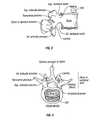
- FIG. 2is a side view of a vertebral body showing the placement of the SEC according to an aspect of the invention.
- FIG. 3is a top view of a vertebral body showing placement of the SEC according to an aspect of the invention.
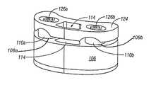
- FIG. 4Ais a front perspective view of the SEC in an unexpanded state according to an aspect of the invention.
- FIG. 4Bis a rear perspective view of the SEC of FIG. 4A according to an aspect of the invention.
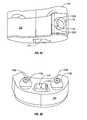
- FIG. 4Cis a rear perspective view of the SEC of FIG. 4A showing details of the hydraulic and bone graft input ports according to an aspect of the invention.
- FIG. 4Dis a perspective view of the SEC of FIG. 4A with the wedge plate removed for clarity.
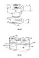
- FIG. 4Eis a perspective view of FIG. 4A showing the cylinders and bone graft perfusing cavity defined by the SEC body according to an aspect of the invention.
- FIG. 4Fshows another view of the wedge plate according to an aspect of the invention.
- FIG. 4Gshows details of the wedge plate and lordosis plate according to an aspect of the invention.
- FIG. 5Ais a front perspective view of the SEC in an expanded state according to an aspect of the invention.
- FIG. 5Bis a top perspective view of the SEC showing the cavity for bone graft perfusion and recesses allowing lateral movement of the wedge according to an aspect of the invention.
- FIG. 5Cis a rear perspective view of the SEC in an expanded state according to an aspect of the invention.
- FIG. 5Dis a perspective view of FIG. 5C with the SEC body removed for clarity.
- FIG. 6is a perspective view of an alternate embodiment of the SEC according to an aspect of the invention.
- FIG. 7Ais a perspective view of a master cylinder for hydraulic control of the SEC according to an aspect of the invention.
- a variety of alternative embodimentsare available, most simply disposable syringes used for piston expansion.
- FIG. 7Bis a view of the interior of FIG. 7A .
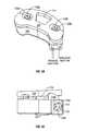
- FIG. 8is a perspective view of an alternate embodiment of the master cylinder according to an aspect of the invention.
- FIG. 9Ais a perspective view of the insertion tool holding the SEC, hydraulic lines and bone graft supply line according to an aspect of the invention.
- FIG. 9Bis a close up view of the insertion tool of FIG. 9A .
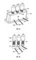
- FIG. 10Ashows one embodiment of a hydraulic line for independent control of multiple slave cylinders according to an aspect of the invention.
- FIG. 10Bshows a close up of the fitting for the hydraulic line of FIG. 10A according to an aspect of the invention.
- vertebral segments or end platesare shown with an average 8 mm gap representing an average intervertebral space.
- a complete discectomyis performed prior to the insertion of the SEC 100 .
- the intervertebral disc occupying space 102is removed using standard techniques including rongeur, curettage, and endplate preparation to bleeding subcondral bone.
- the posterior longitudinal ligamentis divided to permit expansion of the intervertebral space.
- the intervertebral space 102is distracted to about 10 mm using a rotating spatula (Not shown. This is a well-known device that looks like a wide screw driver that can be placed into the disc space horizontally and turned 90 degrees to separate the endplates).
- the SECis inserted posteriorly (in the direction of arrow 102 between the no. 4 and 5 lumbar vertebrae as shown in FIG. 1 (lateral view) or into any selected inververbral space.
- the SECis reduced to small size in its unexpanded state to enable it to be inserted posteriorly through space 102 as shown in Figure.
- the dimensions of the SECare: 12 mm wide, 10 mm high and 28 mm long to facilitate posterior insertion and thereby minimize trauma to the patient and risk of injury to nerve roots.
- the SECcan expand to 16 mm, or 160 percent of its unexpanded size, enabling 20 degrees or more of spinal correction medial and lateral.
- FIGS. 2 and 3are a side view and top view, respectively showing the placement of the SEC 100 on a vertebral body.
- FIG. 4Ashows SEC 100 from the front or anterior position with respect to the vertebral column.
- the SECis shown in a closed or unexpanded position.
- SEC 100comprises a body or block 106 that defines one or more slave cylinders 108 a , 108 b (best seen in FIG. 5A ) for corresponding pistons 110 a , 110 b .
- Pistonsare provided with O rings 112 a , 112 b for a tight seal with the cylinder.
- Block 106also defines a central cavity 114 for infusion of bone graft material into the intervertebral space when the SEC is fully expanded or during the expansion process, as will be explained.
- block 106further defines a central or main input port 116 for attachment of hydraulic lines and a line for transmission of a slurry or liquid bone graft material as will be explained.
- the block 106defines a bone graft infusion conduit that extends from a bone graft input port 119 located in main input port 116 to a bone graft exit port 120 (see FIG. 4D ) located in central cavity 114 for infusion of bone graft material therein.
- Block 106further defines local hydraulic fluid input ports 122 a , 122 b ( FIG. 4C ) that lead to corresponding slave cylinders 108 a , 108 b for driving the pistons and expanding the SEC by remote control from a master cylinder located ex vivo and with greatly increased force as compared to conventional devices.
- each slave piston 110 a , 110 bis independently controlled by a separate hydraulic line 122 a , 122 b connected to a master cylinder (as will be explained with reference to FIGS. 7 a through 8 ) located away from the patient and the site of implantation, thus minimizing active intervention by surgical tools in the immediate vicinity of nerve roots.
- a master cylinderas will be explained with reference to FIGS. 7 a through 8
- SEC block 106easily is modifiable to define a multiplicity of slave cylinders, each controlled independently by a separate hydraulic line, for expanding differentially to provide a substantially infinite variety of space sensitive adjustments for unique applications.
- an anterior/posterior corrective plate or wedge plate 124is movably held in captured engagement on top of pistons 110 a , 110 b by corresponding hold down screws 126 a , and 126 b .
- Plate 124enables spinal correction in the anterior/posterior direction as the cylinders expand vertically.
- Plate 124has a bone-engaging top surface provided with two elongated slots 128 a , 128 b in which the hold down screws sit.
- the elongated slots 128 a , 128 benable ease of expansion and facilitate angles between the pistons by allowing the plate 124 to move laterally slightly as pistons differentially expand.
- the platealso defines cavity 114 for the infusion of bone graft material, that is co-extensive with and the same as cavity 114 defined by the SEC block. This enables perfusion of the bone graft material directly through the bone engaging surface of the wedge plate into the adjacent vertebral body.
- the anterior/posterior corrective plate 124is provided with a downwardly extending edge 130 for engagement with the pistons as they differentially expand, to ensure that wedge plate stays firmly in place.
- Plate 124provides anterior/posterior correction in that it can be angled front to back like a wedge with a correction angle a of 0-5 degrees or more.
- Plate 124also defines bone graft cavity 114 for enabling bone growth conductive or inductive agents to communicate directly with the engaged vertebral endplate.
- the SECis optionally provided with a lordosis base plate 132 that includes a bone engaging surface defining a cavity co-extensive with bone graft cavity 114 for enabling perfusion of bone graft material into the adjacent engaged vertebral body.
- Lordosis base platealso has an anterior/posterior angle b (refer to FIG. 6 ) of 0-5 degrees for correcting lordosis.
- top plate 124 and optional lordosis base plate 132function as two endplates providing a corrective surface that impacts vertebral bodies for spinal correction.
- Lordosis base plate 132includes a bone-engaging surface defining a cavity co-extensive with bone graft cavity 114 for enabling perfusion of bone graft material into the adjacent opposed vertebral body.
- Lordosis base platealso has anterior/posterior angle b of 0-5 degrees for correcting lordosis.
- the wedge plate and lordosis base platecan provide lordotic correction of 10 degrees or more.
- the endplateswill be constructed with 0 degrees of wedge angle anterior to posterior, or 5 degrees. Therefore, the final construct may have parallel endplates (two 0 degree endplates), 5 degrees of lordosis (one 5 degree and one 0 degree endplate), or 10 degrees of lordosis (two 5 degree implants). This implant permits unprecedented flexibility in controlling spinal alignment in the coronal and sagittal planes.
- top plate 124does not need to be configured as a wedge. Where an extreme anterior/posterior correction angle is desired, the top plate and/or base plate may be angled as a wedge with the corresponding correction angles set forth above.
- FIGS. 5A through 5Dshow the SEC in its expanded state.
- Hydraulic fluidflows from a master cylinder ( FIG. 7A ) into the cylinders through separate hydraulic input lines that attach to hydraulic input ports 122 a , 122 b .
- Each hydraulic lineis regulated independently thereby allowing a different quantity of material to fill each cylinder and piston cavity pushing the pistons and medial/lateral wedge plate upward to a desired height for effecting spinal correction.
- the hydraulic fluid communicating the mechanical leverage from the master cylinder to the slave cylinder or syringe and pistonsadvantageously is a time-controlled curable polymer such as methylmethacrylate.
- the viscosity and curing timecan be adjusted by the formulation of an appropriate added catalyst as is well known.
- catalystsare available from LOCTITE Corp., 1001 Trout Brook Crossing, Rocky Hill Conn. 06067. When the polymer cures, it hardens and locks the pistons and thus the desired amount of spinal correction determined by the physician immovably in place.
- the cylinder block 106 and pistons 110 a , 110 bcomprise a biocompatible, substantially incompressible material such as titanium, and preferably type 6-4 titanium alloy. Cylinder block 106 and pistons 110 a , 110 b completely confine the curable polymer that is acting as the hydraulic fluid for elevating the pistons. When the desired spinal correction is achieved by the expanded pistons, the curable polymer solidifies, locking the proper spinal alignment substantially invariantly in place.
- the confinement of the polymer by the titanium pistons and cylinder blockprovides the advantage of making the polymer and the desired amount of spinal alignment substantially impervious to shear and compressive forces.
- injectable bone graft material 134is provided along a separate bone graft input line to bone graft input port 119 for infusion into cavity 114 through bone graft exit port 120 .
- the bone graft input lineis controlled at the master cylinder or from a separate source to enable a pressure induced infusion of bone graft material 134 through cavity 114 of the bone engaging surfaces of the SEC into adjacent vertebral bone.
- the bone graft materialfills, under pressure, the post-expansion space between adjacent vertebral bodies. This achieves substantially complete perfusion of osteo-inductive and/or osteo-conductive bone graft material in the post expansion space between the vertebral bodies resulting in enhanced fusion (refer to FIGS. 5C , 5 D).
- an alternate embodiment of the SECcomprises multiple slave cylinders and corresponding pistons 110 a , 110 b , 110 n are provided in SEC body 106 .
- Each of the multiple slave cylinders and pistons 110 a , 110 b , 110 nis provided with a separate, associated hydraulic line 122 a , 122 b , 122 n that communicates independently with a corresponding one of a plurality of cylinders in the master cylinder for independently controlled expansion of the slave cylinders at multiple elevations in three dimensions (X, Y and Z axes).
- multiple threaded cylindersor disposable syringes
- pistonsare provided, each communicating independently through a separate hydraulic line 122 a , 122 b , 122 n with a corresponding one of the slave cylinders and pistons 110 a , 110 b , 110 n in the LEC.
- the bone engaging surfaces of the multiple pistons 110 a , 110 b , 110 nprovide the corrective surface of the SEC.
- the surgeoncan independently control expansion of the slave pistons in the SEC to achieve multiple elevations in three dimensions for specialized corrective applications.
- a top or wedge plateis not necessary.
- the bone engaging surface 111 of the slave pistons 110 a , 110 b , 110 n in the LECmay be provided with a specialized coating for bone ingrowth such as hydroxyapetite.
- the bone-engaging surface 111 of the SEC pistonsmay be corrugated, or otherwise provided with a series of bone engaging projections or cavities to enhance fusion.
- the hydraulic fluid communicating the mechanical leverage from the master cylinder to the SEC slave cylinders and pistons 110 a , 110 b , 110 nis a time-controlled curable polymer such as methylmethacrylate that locks the SEC immovably in place after curing, at the desired three dimensional expansion.
- injectable bone graft materialis provided along a separate bone graft input line to bone graft input port 119 for infusion into cavity 114 through into the inter body space between the SEC and adjacent bone.
- the surgeon by adjustment of the master cylinderis able to provide remotely a controlled angle of the SEC corrective surface to the medial/lateral (X axis) and in the anterior, posterior direction (Z axis).
- the surgeonalso can adjust the SEC in the vertical plane moving superiorly/inferiorly (Y axis) from the master cylinder or power/flow source to control implant height.
- Y axismoving superiorly/inferiorly
- This aspect of the inventionadvantageously obviates the need to manually manipulate the SEC implant at the site of intervention to achieve desired angles of expansion. Such conventional manual manipulation with surgical tools into the intervention site can require further distracting of nerve roots and cause potential serious trauma to a patient.
- a master cylinder 140located remotely from the patient, provides controlled manipulation and adjustment of the SEC in three dimensions through independent hydraulic control of slave cylinders 110 a , 110 b in the SEC.
- Master cylinder 140comprises a cylinder block 142 , defining two or more threaded cylinders 143 .
- Corresponding screw down threaded pistonsare rotated downward into the threaded cylinders thereby applying force to a hydraulic fluid in corresponding hydraulic control lines that communicate independently with and activate corresponding slave cylinders 110 a , 110 b in the SEC with mechanical leverage.
- the rotational force for applying the mechanical leverage at the slave cylindersis controlled by thread pitch of the threaded pistons in the master cylinder, or in an alternate embodiment controlled by use of syringes, one acting as a master cylinders for each piston or slave cylinder to modulate piston elevation.
- threaded pistons 144 a , 144 bare provided in hydraulic cylinders communicating through hydraulic lines 14 ba , 148 b that are coupled to hydraulic input ports 116 a , 116 b for independent hydraulic control of slave cylinders 110 a , 110 b as previously explained.
- Another threaded cylinder and piston assembly 150is supplied with a quantity of bone graft material in slurry or liquid form and operates in the same way to provide the bone graft material under pressure to the SEC bone graft input port 119 through bone graft supply line 152 .
- bone graft materialis forced under pressure from the master cylinder through cavity 114 and into the intervertebral space.
- a master cylinder 154is provided with two or more cylinders 156 a , 156 b , and associated pistons 157 a , 157 b .
- a lever 158 controlled by the surgeonis attached to each piston. Hydraulic fluid feeds through lines 148 a 148 b into the inserted SEC implant. The lever creates a ratio of 1 pound to 10 pounds of pressure inside the slave cylinders in the SEC and thus against vertebral endplates. Mechanically this provides a 10:1 advantage in lift force for the surgeon. The surgeon's required force application is multiplied via the lever and hydraulic system to create a controlled expansion of the SEC against the endplates as previously described to create any desired spine vertebral correctional effect in three dimensions.
- the pistonexerts 10 pounds of force.
- the piston in the master cylinderdisplaces the hydraulic fluid through hydraulic lines 148 a , 148 b .
- the hydraulic linesare flexible conduit no more than 3 mm in diameter. Thin hydraulic lines are desirable to increase mechanical advantage at the slave cylinders in the SEC. If one pound of pressure is exerted on the handle, the corresponding piston in the SEC would have 10 pounds of lifting force. If each slave piston inside the SEC implant has 200 pounds of lifting force, the required amount of pressure applied by the surgeon to the master piston cylinder is 20 pounds, or one tenth the amount, consistent with the predetermined mechanical advantage.
- the pressure application processis guided by normal surgical principles, by visual checkpoints, and by a safety gauge that illustrates the amount of expansion that has been exerted in direct correlation with the implant expansion process.
- the gaugeindicates the height of the slave pistons and thus the vertical and angular expansion of the SEC. This translates to an ability to clarify the percentage of lateral expansion. That is, if the surgeon chooses to create an angle, he expands the right slave cylinder, for example, 14 mm and left slave cylinder 12 mm.
- the master cylinder 154preferably comprises transparent plastic to enable visual indication of the height of the hydraulic fluid therein, or a translucent plastic syringe to facilitate exact measured infusion of the slave cylinder implant expanding pistons.
- a knob 159 for setting gauge heightis provided in each cylinder.
- An indicator attached to the knobregisters the cylinder height with respect to a fill line, bleed line or maximum height line.
- the master cylinder and slave cylindersare filled with hydraulic fluid. Air is removed by bleeding the cylinders in a well-known manner.
- the knob indicatoris registered to the bleed line.
- a series of incremental marksare provided between the bleed line and the maximum height line to show the surgeon the exact height of the slave cylinder in response to the surgeon's control inputs to the master cylinder.
- the master and slave hydraulic system interactioncan have many equivalent variations.
- the master cylinder function of master cylinder 154also can be provided by one or more syringes. Each syringe acts as a master cylinder and is coupled independently with a corresponding slave cylinder through a thin hydraulic line for independent activation as previously described.
- a single syringe acting as a master cylinderalso may be selectively coupled with one or more slave cylinders for independent activation of the slave cylinders.
- series of gradationsare provided along the length of the syringe that are calibrated to enable the surgeon to effect a precise elevation of a selected piston at the corresponding slave cylinder in the implant.
- the SEC implantalso expands vertically the intervertebral space from 10 mm to 16 mm or more. Additionally, by changing the diameter of the piston inside the master cylinder, the force exerted into the slave cylinder could be multiplied many fold so as to create major force differentials.
- the foregoing featuresprovide the surgeon with an ability to establish a spinal correction system that is a function of the needed change to correct a deformity, so as to produce normal alignment.
- hydraulic control lines 148 and bone graft supply line 152are characterized by a minimal size and are provided in the interior of a very narrow insertion tool 180 ( FIGS. 9A and 9B ).
- the insertion tool 180is small enough to insert the SEC 100 posteriorly into the narrow insertion opening without risk of serious trauma to the patient.
- An enlarged view of the insertion tool 180(simplified for clarity) is shown in FIG. 9B .
- the insertion tool 180includes a handle 182 and hollow interior for housing hydraulic control lines and a bone graft supply line (not shown for clarity).
- the hydraulic control lines and bone graft supply lineconnect through a proximal end of the insertion tool to the master cylinder.
- a distal or insertion end of the toolholds the SEC 100 .
- the insertion end of the insertion toolconformably fits in the SEC hydraulic input port 116 .
- Hydraulic control lines and the bone graft supply lineare connected to the hydraulic input ports 122 a , 122 b and bone graft supply input port respectively, prior to surgery.
- the bone graft supply and hydraulic control linesare safely retracted after the SEC is positioned.
- the hydraulic linescan be released by cutting after the operation since the hydraulic fluid hardens in place.
- the hydraulic fluid controlling the movement of the SECis a time-controlled curable polymer that hardens after a pre-determined time period, locking the SEC insert immovably in a desired expanded position.
- the hydraulic fluidis preferably methylmethacrylate or other similar inexpensive polymer, with a time controlled curing rate.
- Time-controlled curable polymerstypically comprise a catalyst and a polymer.
- the catalystcan be formulated in a well-known manner to determine the time at which the polymer solidifies.
- Such time-controlled curable polymersare commercially available from several manufacturers such as LOCTITE Corp., Henkel-Loctite, 1001 Trout Brook Crossing Rocky Hill, Conn. 06067.
- any equivalent curable polymerthat has a first flowable state for conveying hydraulic force, and that transitions to a second solid state upon curing may be employed.
- the curable polymertransfers the application of force hydraulically from the master cylinder to the slave cylinders, such that corrective action is achieved by elevating the slave pistons.
- the curable polymertransitions to a second solid state upon curing such that the corrective elevation of the slave pistons is locked in place.
- Such an equivalent curable polymeris a polymer that is cured through the application of either visible or ultraviolet light or other radiation source which activates the polymer to transition to a solid state.
- Another methylmethacrylate liquid polymer when combined with powderbecomes a viscous fluid as soon as the powder and liquid are blended; it is initially thin and free flowing. Gradually, in minutes, it begins to thicken, transforming state through paste and putty to cement-like solid once inside the pistons, thus fixing the SEC at a precise correction amount in its expanded position.
- UV10LC-12made by MASTER BOND Inc., of Hackensack, N.J.
- Such polymersare characterized by a fast cure time cure upon exposure to a visible or a UV light source. Depending upon the intensity of the light source, cure times range from a few seconds to less than a minute.
- an extremely thin fiber optic linemay be incorporated as an additional line along with the multiple hydraulic lines shown in Figure for conveying light from a light source directly to the polymer in the slave cylinders to effect curing.
- a curable polymermay be activated by a radiation source such as low level electron beam radiation to cure or initiate curing.
- a radiation sourcesuch as low level electron beam radiation to cure or initiate curing.
- An electron beamadvantageously can penetrate through material that is opaque to UV light and can be applied directly to lock the pistons in their elevated or corrective position.
- the amount of applied stress required to cause failure of the corrective implantis substantial due to the confinement of the cured polymer completely within the body of the implant, that is, the cylinder block that is comprised of 6-4 titanium. This is particularly advantageous since the confinement within the titanium body enables the corrective position of the implant to withstand compressive forces up to the structural failure limit of the titanium body; that is, to withstand compressive forces in a range of from 8000 up to 12,000 Newtons.
- a hydraulic line 200is provided for remote hydraulic control of a plurality of slave cylinders of the SEC from a master cylinder.
- Hydraulic line 200comprises a plurality of individual hydraulic lines 202 disposed about a central axis. Each hydraulic line 202 provides independent activation of a separate slave cylinder from a master cylinder as previously explained.
- a bone graft supply line 204is provided along the central axis of line 200 .
- Individual hydraulic lines 202can be aligned and connected with corresponding slave cylinder input ports prior to insertion of the SEC for providing independent hydraulic control to each of the slave cylinders.
- a threaded end 206can be inserted into a similarly threaded central input port 116 of the SEC to prevent pull out.
- remote hydraulic control of a spinal implantis particularly advantageous in a posterior insertion procedure because there is no anatomic room for mechanical linkage or tooling in the proximity of the adjacent spinal cord and neurovascular complex.
- the hydraulic control provided by the present inventionprovides significant mechanical leverage and thus increased force to an extent that has not previously been possible. Further, such hydraulic force is selective in both direction and magnitude of its application.
- the SECprovides advantages over currently existing technology that include correction of coronal plane deformity; introduction of interbody lordosis and early stabilization of the interbody space with rigidity that is greater than present spacer devices. This early stability may improve post-operative pain, preclude the need for posterior implants including pedicle screws, and improve the rate of successful arthrodesis. Importantly, the SEC provides improvement of space available for the neural elements while improving lordosis. Traditional implants are limited to spacer effects, as passive fillers of the intervertebral disc locations awaiting eventual fusion if and when bone graft in and around the implant fuses. By expanding and ‘morphing’ into the calculated shape which physiologically corrects spine angulation, the SEC immediately fixes the spine in its proper, painless, functional position. As infused osteoinductive/osteoconductive bone graft materials heal, the patient becomes well and the implant becomes inert and quiescent, embedded in bone, and no longer needed.
- equivalent expansion surfacescan be provided for stabilizing the expanding SEC against the bone.
- Other compositions of additivesmay be used for the hydraulic fluid that achieves remote controlled expansion of the SEC in three dimensions.
- various types of biogenic fluid material for enhancing bone growthmay be injected through one or more lines to the SEC and different exit apertures may be provided to apply bone graft material to fill the intervertebral space, without departing from the scope of the invention.
- the inventioncan comprise a spinal implant that incorporates load or pressure sensors that register differential pressure and pressure intensity exerted on the back's engaging surface of the implant by the patient's vertebrae end plates to generate corrective signals, for example by computer control, that are used, e.g. by the surgeon or by a computer controlled mechanism to realign the patient's spine.
- the inventionmay further include a system that makes these adjustments, responsive to sensor signals, in real time and on a continual basis, such that the shapes of the implant changes to realign the patient's spine or mechanism.
- such systemis contemplated for use in setting the positions of the pistons during installation of the implant.
- the inventionalso comprises the use of any of a solid or tubular coiled spring and a compressible fluid, e.g. a gas, such as air, in the cylinders to provide some movement of the implant plates to accommodate the patient's spinal movement.
- a compressible fluide.g. a gas, such as air
- the implant itselfcan be made of, for example, such materials as titanium, 64 titanium, or an alloy thereof, 316 or 321 stainless steel, biodegradable and biologically active materials, e.g. stem cells, and polymers, such as semi-crystalline, high purity polymers comprised of repeating monomers of two ether groups and a keytone group, e.g. polyaryetheretherketone (PEEK)TM, or teflon.
- PEEKpolyaryetheretherketone
- the implantmay provide two or more pistons that are operated concurrently to provide coordinated medial/lateral adjustment of a patient's spine for scoliosis, with anterior/posterior adjustment of the patient's spine to create natural lordosis, with relative anterior expansion greater than posterior expansion.
Landscapes
- Health & Medical Sciences (AREA)
- Engineering & Computer Science (AREA)
- Biomedical Technology (AREA)
- Orthopedic Medicine & Surgery (AREA)
- Transplantation (AREA)
- Neurology (AREA)
- Heart & Thoracic Surgery (AREA)
- Oral & Maxillofacial Surgery (AREA)
- Cardiology (AREA)
- Vascular Medicine (AREA)
- Life Sciences & Earth Sciences (AREA)
- Animal Behavior & Ethology (AREA)
- General Health & Medical Sciences (AREA)
- Public Health (AREA)
- Veterinary Medicine (AREA)
- Physical Education & Sports Medicine (AREA)
- Prostheses (AREA)
Abstract
Description
Claims (56)
Priority Applications (11)
| Application Number | Priority Date | Filing Date | Title |
|---|---|---|---|
| US11/535,432US7985256B2 (en) | 2005-09-26 | 2006-09-26 | Selectively expanding spine cage, hydraulically controllable in three dimensions for enhanced spinal fusion |
| US11/692,800US8070813B2 (en) | 2005-09-26 | 2007-03-28 | Selectively expanding spine cage, hydraulically controllable in three dimensions for vertebral body replacement |
| PCT/US2007/079474WO2008039811A2 (en) | 2006-09-26 | 2007-09-26 | Selectively expanding spine cage, hydraulically controllable in three dimensions for enhanced spinal fusion |
| US11/981,150US8394143B2 (en) | 2005-09-26 | 2007-10-31 | Selectively expanding spine cage, hydraulically controllable in three dimensions for enhanced spinal fusion |
| US11/981,452US20080161933A1 (en) | 2005-09-26 | 2007-10-31 | Selectively expanding spine cage, hydraulically controllable in three dimensions for vertebral body replacement |
| US13/183,080US8454695B2 (en) | 2005-09-26 | 2011-07-14 | Selectively expanding spine cage, hydraulically controllable in three dimensions for enhanced spinal fusion |
| US13/311,487US8480741B2 (en) | 2005-09-26 | 2011-12-05 | Selectively expanding spine cage, hydraulically controllable in three dimensions for vertebral body replacement |
| US13/799,047US9028550B2 (en) | 2005-09-26 | 2013-03-13 | Selectively expanding spine cage with enhanced bone graft infusion |
| US14/689,634US9814600B2 (en) | 2005-09-26 | 2015-04-17 | Selectively expanding spine cage with enhanced bone graft infusion |
| US15/807,835US10610374B2 (en) | 2005-09-26 | 2017-11-09 | Selectively expanding spine cage with enhanced bone graft infusion |
| US16/829,333US11564806B2 (en) | 2005-09-26 | 2020-03-25 | Selectively expanding spine cage with enhanced bone graft infusion |
Applications Claiming Priority (2)
| Application Number | Priority Date | Filing Date | Title |
|---|---|---|---|
| US72078405P | 2005-09-26 | 2005-09-26 | |
| US11/535,432US7985256B2 (en) | 2005-09-26 | 2006-09-26 | Selectively expanding spine cage, hydraulically controllable in three dimensions for enhanced spinal fusion |
Related Child Applications (3)
| Application Number | Title | Priority Date | Filing Date |
|---|---|---|---|
| US11/692,800Continuation-In-PartUS8070813B2 (en) | 2005-09-26 | 2007-03-28 | Selectively expanding spine cage, hydraulically controllable in three dimensions for vertebral body replacement |
| US11/981,150DivisionUS8394143B2 (en) | 2005-09-26 | 2007-10-31 | Selectively expanding spine cage, hydraulically controllable in three dimensions for enhanced spinal fusion |
| US13/183,080ContinuationUS8454695B2 (en) | 2005-09-26 | 2011-07-14 | Selectively expanding spine cage, hydraulically controllable in three dimensions for enhanced spinal fusion |
Publications (2)
| Publication Number | Publication Date |
|---|---|
| US20070093901A1 US20070093901A1 (en) | 2007-04-26 |
| US7985256B2true US7985256B2 (en) | 2011-07-26 |
Family
ID=39230930
Family Applications (3)
| Application Number | Title | Priority Date | Filing Date |
|---|---|---|---|
| US11/535,432Active2030-05-26US7985256B2 (en) | 2005-09-26 | 2006-09-26 | Selectively expanding spine cage, hydraulically controllable in three dimensions for enhanced spinal fusion |
| US11/981,150Active2030-04-28US8394143B2 (en) | 2005-09-26 | 2007-10-31 | Selectively expanding spine cage, hydraulically controllable in three dimensions for enhanced spinal fusion |
| US13/183,080ActiveUS8454695B2 (en) | 2005-09-26 | 2011-07-14 | Selectively expanding spine cage, hydraulically controllable in three dimensions for enhanced spinal fusion |
Family Applications After (2)
| Application Number | Title | Priority Date | Filing Date |
|---|---|---|---|
| US11/981,150Active2030-04-28US8394143B2 (en) | 2005-09-26 | 2007-10-31 | Selectively expanding spine cage, hydraulically controllable in three dimensions for enhanced spinal fusion |
| US13/183,080ActiveUS8454695B2 (en) | 2005-09-26 | 2011-07-14 | Selectively expanding spine cage, hydraulically controllable in three dimensions for enhanced spinal fusion |
Country Status (2)
| Country | Link |
|---|---|
| US (3) | US7985256B2 (en) |
| WO (1) | WO2008039811A2 (en) |
Cited By (166)
| Publication number | Priority date | Publication date | Assignee | Title |
|---|---|---|---|---|
| US20080147194A1 (en)* | 2005-09-26 | 2008-06-19 | Innvotec Srgical, Inc. | Selectively expanding spine cage, hydraulically controllable in three dimensions for enhanced spinal fusion |
| US20100145456A1 (en)* | 2008-12-10 | 2010-06-10 | Simpson Philip J | Lockable spinal implant |
| US20110071536A1 (en)* | 2009-09-18 | 2011-03-24 | Kleiner Jeffrey | Bone graft delivery device and method of using the same |
| US20110130835A1 (en)* | 2008-12-10 | 2011-06-02 | Innvotec Surgical, Inc. | Adjustable Distraction Cage With Linked Locking Mechanisms |
| US20110138948A1 (en)* | 2009-07-22 | 2011-06-16 | Jimenez Omar F | Coaxial screw gear sleeve mechanism |
| US8088163B1 (en) | 2008-02-06 | 2012-01-03 | Kleiner Jeffrey B | Tools and methods for spinal fusion |
| USD656610S1 (en) | 2009-02-06 | 2012-03-27 | Kleiner Jeffrey B | Spinal distraction instrument |
| WO2012040152A1 (en) | 2010-09-20 | 2012-03-29 | Jeffrey Kleiner | Fusion cage with combined biological delivery system |
| US8366748B2 (en) | 2008-12-05 | 2013-02-05 | Kleiner Jeffrey | Apparatus and method of spinal implant and fusion |
| US8480741B2 (en) | 2005-09-26 | 2013-07-09 | Coalign Innovations, Inc. | Selectively expanding spine cage, hydraulically controllable in three dimensions for vertebral body replacement |
| US8529628B2 (en) | 2009-06-17 | 2013-09-10 | Trinity Orthopedics, Llc | Expanding intervertebral device and methods of use |
| US20130253650A1 (en)* | 2008-12-10 | 2013-09-26 | Coalign Innovations, Inc. | Adjustable Distraction Cage With Linked Locking Mechanisms |
| US8685031B2 (en) | 2009-09-18 | 2014-04-01 | Spinal Surgical Strategies, Llc | Bone graft delivery system |
| US8906100B2 (en) | 2008-12-31 | 2014-12-09 | Ex Technology, Llc | Methods and apparatus for vertebral body distraction and fusion employing flexure members |
| US8932302B2 (en) | 2011-07-22 | 2015-01-13 | Spinex Tec, Llc | Methods and apparatus for insertion of vertebral body distraction and fusion devices |
| US8932355B2 (en) | 2008-02-22 | 2015-01-13 | Coalign Innovations, Inc. | Spinal implant with expandable fixation |
| US8940049B1 (en) | 2014-04-01 | 2015-01-27 | Ex Technology, Llc | Expandable intervertebral cage |
| USD723682S1 (en) | 2013-05-03 | 2015-03-03 | Spinal Surgical Strategies, Llc | Bone graft delivery tool |
| US9028550B2 (en) | 2005-09-26 | 2015-05-12 | Coalign Innovations, Inc. | Selectively expanding spine cage with enhanced bone graft infusion |
| US9060877B2 (en) | 2009-09-18 | 2015-06-23 | Spinal Surgical Strategies, Llc | Fusion cage with combined biological delivery system |
| US20150190181A1 (en)* | 2004-08-03 | 2015-07-09 | K Spine, Inc. | Facet device and method |
| US9149364B2 (en) | 2008-03-07 | 2015-10-06 | DePuy Synthes Products, Inc. | Expandable interbody spacer device |
| US9173694B2 (en) | 2009-09-18 | 2015-11-03 | Spinal Surgical Strategies, Llc | Fusion cage with combined biological delivery system |
| US9186193B2 (en) | 2009-09-18 | 2015-11-17 | Spinal Surgical Strategies, Llc | Fusion cage with combined biological delivery system |
| US9211195B2 (en) | 2009-10-13 | 2015-12-15 | Nicholas Poulos | Expandable interbody implant and method |
| US9216096B2 (en) | 2010-03-16 | 2015-12-22 | Pinnacle Spine Group, Llc | Intervertebral implants and related tools |
| US9247943B1 (en) | 2009-02-06 | 2016-02-02 | Kleiner Intellectual Property, Llc | Devices and methods for preparing an intervertebral workspace |
| USD750249S1 (en) | 2014-10-20 | 2016-02-23 | Spinal Surgical Strategies, Llc | Expandable fusion cage |
| US9320610B2 (en) | 2011-08-16 | 2016-04-26 | Stryker European Holdings I, Llc | Expandable implant |
| US9380932B1 (en) | 2011-11-02 | 2016-07-05 | Pinnacle Spine Group, Llc | Retractor devices for minimally invasive access to the spine |
| US9445914B2 (en) | 2010-09-30 | 2016-09-20 | Stryker European Holdings I, Llc | Surgical implant with guiding rail |
| US9486328B2 (en) | 2014-04-01 | 2016-11-08 | Ex Technology, Llc | Expandable intervertebral cage |
| US9510955B2 (en) | 2012-05-18 | 2016-12-06 | Trinity Orthopedics, Llc | Articulating interbody cage and methods thereof |
| US9622878B2 (en) | 2014-11-12 | 2017-04-18 | Robert Thomas Grotz | Universally expanding cage |
| US9629729B2 (en) | 2009-09-18 | 2017-04-25 | Spinal Surgical Strategies, Llc | Biological delivery system with adaptable fusion cage interface |
| US9717604B2 (en) | 2008-03-31 | 2017-08-01 | Stryker European Holdings I, Llc | Spinal implant apparatus and methods |
| USD797290S1 (en) | 2015-10-19 | 2017-09-12 | Spinal Surgical Strategies, Llc | Bone graft delivery tool |
| US9782271B2 (en) | 2008-02-28 | 2017-10-10 | Stryker European Holdings I, Llc | Expandable intervertebral implant |
| US9867717B2 (en) | 2009-03-19 | 2018-01-16 | Ex Technology, Llc | Stable device for intervertebral distraction and fusion |
| US9974662B2 (en) | 2016-06-29 | 2018-05-22 | Globus Medical, Inc. | Expandable fusion device and method of installation thereof |
| US9980715B2 (en) | 2014-02-05 | 2018-05-29 | Trinity Orthopedics, Llc | Anchor devices and methods of use |
| EP3357459A1 (en) | 2017-02-03 | 2018-08-08 | Spinal Surgical Strategies, LLC | Bone graft delivery device with positioning handle |
| US10052215B2 (en) | 2016-06-29 | 2018-08-21 | Globus Medical, Inc. | Expandable fusion device and method of installation thereof |
| US10070970B2 (en) | 2013-03-14 | 2018-09-11 | Pinnacle Spine Group, Llc | Interbody implants and graft delivery systems |
| US10219914B2 (en) | 2015-11-10 | 2019-03-05 | Globus Medical, Inc. | Stabilized expandable intervertebral spacer |
| US20190083275A1 (en)* | 2017-09-15 | 2019-03-21 | Stryker European Holdings I, Llc | Intervertebral Body Fusion Device Expanded With Hardening Material |
| US10245159B1 (en) | 2009-09-18 | 2019-04-02 | Spinal Surgical Strategies, Llc | Bone graft delivery system and method for using same |
| US10285825B2 (en) | 2016-04-07 | 2019-05-14 | Howmedica Osteonics Corp. | Surgical insertion instruments |
| US10292833B2 (en) | 2013-11-27 | 2019-05-21 | Howmedica Osteonics Corp. | Structurally supporting insert for spinal fusion cage |
| USD853560S1 (en) | 2008-10-09 | 2019-07-09 | Nuvasive, Inc. | Spinal implant insertion device |
| US10342675B2 (en) | 2013-03-11 | 2019-07-09 | Stryker European Holdings I, Llc | Expandable implant |
| US10349982B2 (en) | 2011-11-01 | 2019-07-16 | Nuvasive Specialized Orthopedics, Inc. | Adjustable magnetic devices and methods of using same |
| US10470891B2 (en) | 2016-09-12 | 2019-11-12 | Howmedica Osteonics Corp. | Interbody implant with independent control of expansion at multiple locations |
| US10478232B2 (en) | 2009-04-29 | 2019-11-19 | Nuvasive Specialized Orthopedics, Inc. | Interspinous process device and method |
| US10485675B2 (en) | 2016-10-26 | 2019-11-26 | Howmedica Osteonics Corp. | Expandable interbody implant with lateral articulation |
| US10548743B2 (en) | 2014-12-16 | 2020-02-04 | Globus Medical, Inc. | Expandable fusion devices and methods of installation thereof |
| US10548738B2 (en) | 2016-04-07 | 2020-02-04 | Howmedica Osteonics Corp. | Expandable interbody implant |
| US10617453B2 (en) | 2015-10-16 | 2020-04-14 | Nuvasive Specialized Orthopedics, Inc. | Adjustable devices for treating arthritis of the knee |
| US10617449B2 (en) | 2016-01-08 | 2020-04-14 | Stryker European Holdings I, Llc | Tap marker |
| US10646262B2 (en) | 2011-02-14 | 2020-05-12 | Nuvasive Specialized Orthopedics, Inc. | System and method for altering rotational alignment of bone sections |
| US10660675B2 (en) | 2010-06-30 | 2020-05-26 | Nuvasive Specialized Orthopedics, Inc. | External adjustment device for distraction device |
| US10702397B2 (en) | 2009-04-16 | 2020-07-07 | Howmedica Osteonics Corp. | Insertion handle for surgical implants |
| US10729470B2 (en) | 2008-11-10 | 2020-08-04 | Nuvasive Specialized Orthopedics, Inc. | External adjustment device for distraction device |
| US10743794B2 (en) | 2011-10-04 | 2020-08-18 | Nuvasive Specialized Orthopedics, Inc. | Devices and methods for non-invasive implant length sensing |
| US10751094B2 (en) | 2013-10-10 | 2020-08-25 | Nuvasive Specialized Orthopedics, Inc. | Adjustable spinal implant |
| US10835290B2 (en) | 2015-12-10 | 2020-11-17 | Nuvasive Specialized Orthopedics, Inc. | External adjustment device for distraction device |
| US10864086B2 (en) | 2010-02-24 | 2020-12-15 | Globus Medical, Inc. | Expandable intervertebral spacer and method of posterior insertion thereof |
| US10918425B2 (en) | 2016-01-28 | 2021-02-16 | Nuvasive Specialized Orthopedics, Inc. | System and methods for bone transport |
| US10940018B2 (en) | 2016-05-20 | 2021-03-09 | Howmedica Osteonics Corp. | Expandable interbody implant with lordosis correction |
| US10973656B2 (en) | 2009-09-18 | 2021-04-13 | Spinal Surgical Strategies, Inc. | Bone graft delivery system and method for using same |
| US11083597B2 (en) | 2017-09-15 | 2021-08-10 | Howmedica Osteonics Corp. | Instruments for expandable interbody implants |
| US11191650B2 (en) | 2020-02-03 | 2021-12-07 | Globus Medical Inc. | Expandable fusions devices, instruments, and methods thereof |
| US11191579B2 (en) | 2012-10-29 | 2021-12-07 | Nuvasive Specialized Orthopedics, Inc. | Adjustable devices for treating arthritis of the knee |
| US11202707B2 (en) | 2008-03-25 | 2021-12-21 | Nuvasive Specialized Orthopedics, Inc. | Adjustable implant system |
| US11207110B2 (en) | 2009-09-04 | 2021-12-28 | Nuvasive Specialized Orthopedics, Inc. | Bone growth device and method |
| US11234835B2 (en) | 2019-03-05 | 2022-02-01 | Octagon Spine Llc | Transversely expandable minimally invasive intervertebral cage |
| US11234849B2 (en) | 2006-10-20 | 2022-02-01 | Nuvasive Specialized Orthopedics, Inc. | Adjustable implant and method of use |
| US11246694B2 (en) | 2014-04-28 | 2022-02-15 | Nuvasive Specialized Orthopedics, Inc. | System for informational magnetic feedback in adjustable implants |
| US11253372B2 (en)* | 2019-03-09 | 2022-02-22 | Iorthopedics, Inc. | Universally expanding cages |
| US11298240B2 (en) | 2020-06-16 | 2022-04-12 | Globus Medical, Inc. | Expanding intervertebral implants |
| US11304729B2 (en) | 2009-02-23 | 2022-04-19 | Nuvasive Specialized Orthhopedics, Inc. | Non-invasive adjustable distraction system |
| USRE49061E1 (en) | 2012-10-18 | 2022-05-10 | Nuvasive Specialized Orthopedics, Inc. | Intramedullary implants for replacing lost bone |
| US11357547B2 (en) | 2014-10-23 | 2022-06-14 | Nuvasive Specialized Orthopedics Inc. | Remotely adjustable interactive bone reshaping implant |
| US11357640B2 (en) | 2020-07-08 | 2022-06-14 | Globus Medical Inc. | Expandable interbody fusions devices |
| US11357549B2 (en) | 2004-07-02 | 2022-06-14 | Nuvasive Specialized Orthopedics, Inc. | Expandable rod system to treat scoliosis and method of using the same |
| US11395626B2 (en) | 2006-12-07 | 2022-07-26 | DePuy Synthes Products, Inc. | Sensor for intervertebral fusion indicia |
| US11426258B2 (en) | 2018-12-21 | 2022-08-30 | Stryker European Operations Limited | Tap marker with flexible extension and associated instruments |
| US11439449B2 (en) | 2014-12-26 | 2022-09-13 | Nuvasive Specialized Orthopedics, Inc. | Systems and methods for distraction |
| US11491020B2 (en) | 2020-07-09 | 2022-11-08 | Globus Medical, Inc. | Articulating and expandable interbody fusions devices |
| US11497622B2 (en) | 2019-03-05 | 2022-11-15 | Ex Technology, Llc | Transversely expandable minimally invasive intervertebral cage and insertion and extraction device |
| US11577097B2 (en) | 2019-02-07 | 2023-02-14 | Nuvasive Specialized Orthopedics, Inc. | Ultrasonic communication in medical devices |
| US11589901B2 (en) | 2019-02-08 | 2023-02-28 | Nuvasive Specialized Orthopedics, Inc. | External adjustment device |
| US11612416B2 (en) | 2015-02-19 | 2023-03-28 | Nuvasive Specialized Orthopedics, Inc. | Systems and methods for vertebral adjustment |
| RU2792942C1 (en)* | 2022-02-10 | 2023-03-28 | федеральное государственное бюджетное образовательное учреждение высшего образования "Северо-Западный государственный медицинский университет имени И.И. Мечникова" Министерства здравоохранения Российской Федерации | Truss reinforcing cage for forming a combined implant to replace a removed disc during operations on the thoracic and lumbar spine and a jig-injector for installing and filling a truss reinforcing cage |
| US11628068B2 (en) | 2013-03-15 | 2023-04-18 | Globus Medical, Inc. | Expandable intervertebral implant |
| US11666457B2 (en) | 2009-10-15 | 2023-06-06 | Globus Medical Inc. | Expandable fusion device and method of installation thereof |
| US11666455B2 (en) | 2009-09-18 | 2023-06-06 | Spinal Surgical Strategies, Inc., A Nevada Corporation | Bone graft delivery devices, systems and kits |
| US11690733B2 (en) | 2009-10-15 | 2023-07-04 | Globus Medical Inc. | Expandable fusion device and method of installation thereof |
| US11696836B2 (en) | 2013-08-09 | 2023-07-11 | Nuvasive, Inc. | Lordotic expandable interbody implant |
| US11701236B2 (en) | 2013-03-01 | 2023-07-18 | Globus Medical, Inc. | Articulating expandable intervertebral implant |
| US11717420B2 (en) | 2011-09-30 | 2023-08-08 | Globus Medical, Inc. | Expandable fusion device and method of installation thereof |
| US11723780B2 (en) | 2015-07-17 | 2023-08-15 | Globus Medical, Inc. | Intervertebral spacer and plate |
| US11737787B1 (en) | 2021-05-27 | 2023-08-29 | Nuvasive, Inc. | Bone elongating devices and methods of use |
| US11744714B2 (en) | 2015-05-21 | 2023-09-05 | Globus Medical Inc. | Device and method for deployment of an anchoring device for intervertebral spinal fusion |
| US11759328B2 (en) | 2019-09-06 | 2023-09-19 | Globus Medical Inc. | Expandable motion preservation spacer |
| US11766252B2 (en) | 2013-07-31 | 2023-09-26 | Nuvasive Specialized Orthopedics, Inc. | Noninvasively adjustable suture anchors |
| US11766340B2 (en) | 2013-03-01 | 2023-09-26 | Globus Medical, Inc. | Articulating expandable intervertebral implant |
| US11771564B2 (en) | 2013-02-15 | 2023-10-03 | Globus Medical Inc. | Articulating and expandable vertebral implant |
| US11801187B2 (en) | 2016-02-10 | 2023-10-31 | Nuvasive Specialized Orthopedics, Inc. | Systems and methods for controlling multiple surgical variables |
| US11801148B2 (en) | 2010-06-25 | 2023-10-31 | Globus Medical, Inc. | Expandable fusion device and method of installation thereof |
| US11806054B2 (en) | 2021-02-23 | 2023-11-07 | Nuvasive Specialized Orthopedics, Inc. | Adjustable implant, system and methods |
| US11813175B2 (en) | 2012-12-31 | 2023-11-14 | Globus Medical, Inc. | Spinous process fixation system and methods thereof |
| US11826263B2 (en) | 2010-09-03 | 2023-11-28 | Globus Medical, Inc. | Expandable fusion device and method of installation thereof |
| US11839410B2 (en) | 2012-06-15 | 2023-12-12 | Nuvasive Inc. | Magnetic implants with improved anatomical compatibility |
| US11844703B2 (en) | 2010-06-25 | 2023-12-19 | Globus Medical Inc. | Expandable fusion device and method of installation thereof |
| US11857437B2 (en) | 2010-09-03 | 2024-01-02 | Globus Medical, Inc. | Expandable fusion device and method of installation thereof |
| US11857226B2 (en) | 2013-03-08 | 2024-01-02 | Nuvasive Specialized Orthopedics | Systems and methods for ultrasonic detection of device distraction |
| US11871974B2 (en) | 2007-10-30 | 2024-01-16 | Nuvasive Specialized Orthopedics, Inc. | Skeletal manipulation method |
| US11883080B1 (en) | 2022-07-13 | 2024-01-30 | Globus Medical, Inc | Reverse dynamization implants |
| US11890203B2 (en) | 2009-10-15 | 2024-02-06 | Globus Medical, Inc | Expandable fusion device and method of installation thereof |
| US11896492B2 (en) | 2013-03-15 | 2024-02-13 | Globus Medical, Inc. | Expandable intervertebral implant |
| US11896499B2 (en) | 2021-12-02 | 2024-02-13 | Globus Medical, Inc | Expandable fusion device with integrated deployable retention spikes |
| US11896493B2 (en) | 2015-12-16 | 2024-02-13 | Globus Medical, Inc | Expandable intervertebral spacer |
| US11896496B2 (en) | 2015-05-21 | 2024-02-13 | Globus Medical, Inc. | Device and method for deployment of an anchoring device for intervertebral spinal fusion |
| US11903844B2 (en) | 2015-05-21 | 2024-02-20 | Globus Medical, Inc. | Device and method for deployment of an anchoring device for intervertebral spinal fusion |
| US11911291B2 (en) | 2015-09-02 | 2024-02-27 | Globus Medical, Inc. | Implantable systems, devices and related methods |
| US11918489B2 (en) | 2021-04-02 | 2024-03-05 | Nuvasive Inc. | Expansion driver |
| US11925389B2 (en) | 2008-10-13 | 2024-03-12 | Nuvasive Specialized Orthopedics, Inc. | Spinal distraction system |
| US11925565B2 (en) | 2014-02-07 | 2024-03-12 | Globus Medical Inc. | Variable lordosis spacer and related methods of use |
| US11944551B2 (en) | 2012-12-11 | 2024-04-02 | Globus Medical, Inc. | Expandable vertebral implant |
| US11998455B2 (en) | 2016-09-14 | 2024-06-04 | Globus Medical, Inc. | Systems and methods for expandable corpectomy spacer implantation |
| US12011365B2 (en) | 2022-07-18 | 2024-06-18 | Octagon Spine Llc | Transversely expandable minimally invasive inter vertebral cage |
| US12011369B2 (en) | 2010-09-03 | 2024-06-18 | Globus Medical Inc. | Expandable interspinous process fixation device |
| US12011368B2 (en) | 2015-05-14 | 2024-06-18 | Globus Medical, Inc | Expandable inter vertebral implants and methods of installation thereof |
| US12011364B2 (en) | 2022-06-15 | 2024-06-18 | Globus Medical, Inc | Expandable footprint implant |
| US12016785B2 (en) | 2015-09-02 | 2024-06-25 | Globus Medical Inc | Expandable intervertebral fusion devices and methods of installation thereof |
| US12023073B2 (en) | 2021-08-03 | 2024-07-02 | Nuvasive Specialized Orthopedics, Inc. | Adjustable implant |
| US12029659B2 (en) | 2015-12-15 | 2024-07-09 | Globus Medical, Inc. | Stabilized intervertebral spacer |
| US12029658B2 (en) | 2020-07-09 | 2024-07-09 | Globus Medical, Inc. | Intradiscal fixation systems |
| US12059179B2 (en) | 2016-02-02 | 2024-08-13 | Globus Medical, Inc. | Expandable spinal fixation system |
| US12059358B2 (en) | 2010-09-03 | 2024-08-13 | Globus Medical Inc. | Expandable fusion device and method of installation thereof |
| US12097126B2 (en) | 2021-09-29 | 2024-09-24 | Ex Technology, Llc | Expandable intervertebral cage |
| US12138177B2 (en) | 2017-11-09 | 2024-11-12 | Globus Medical Inc. | Expandable intervertebral implant |
| US12161563B2 (en) | 2016-09-14 | 2024-12-10 | Globus Medical, Inc. | Systems and methods for expandable corpectomy spacer implantation |
| US12167970B2 (en) | 2013-03-15 | 2024-12-17 | Globus Medical, Inc. | Expandable inter vertebral implant |
| US12213890B2 (en) | 2015-07-17 | 2025-02-04 | Globus Medical, Inc. | Intervertebral spacer and plate |
| US12213708B2 (en) | 2020-09-08 | 2025-02-04 | Nuvasive Specialized Orthopedics, Inc. | Remote control module for adjustable implants |
| US12220323B2 (en) | 2019-07-18 | 2025-02-11 | Globus Medical, Inc. | Expanding intervertebral implants |
| US12232975B2 (en) | 2008-02-22 | 2025-02-25 | Howmedica Osteonics Corp. | Lockable spinal implant |
| US12232976B2 (en) | 2010-09-03 | 2025-02-25 | Globus Medical, Inc. | Expandable fusion device and method of installation thereof |
| US12251317B2 (en) | 2010-09-03 | 2025-03-18 | Globus Medical, Inc. | Expandable fusion device and method of installation thereof |
| US12251321B2 (en) | 2013-02-25 | 2025-03-18 | Globus Medical, Inc. | Expandable intervertebral implant |
| US12263092B2 (en) | 2019-12-20 | 2025-04-01 | Globus Medical Inc. | Stabilizing vertebrae with articulating implants |
| US12279971B2 (en) | 2010-04-12 | 2025-04-22 | Globus Medical, Inc. | Angling inserter tool for expandable vertebral implant |
| US12279972B2 (en) | 2008-05-22 | 2025-04-22 | Spinal Surgical Strategies, Inc. | Spinal fusion cage system with inserter |
| US12324745B2 (en) | 2020-01-23 | 2025-06-10 | Globus Medical Inc. | Articulating expandable interbody fusions devices |
| US12324748B2 (en) | 2021-12-02 | 2025-06-10 | Globus Medical, Inc. | Expandable fusion device with integrated deployable retention spikes |
| US12350170B2 (en) | 2013-03-15 | 2025-07-08 | Globus Medical, Inc. | Expandable intervertebral implant |
| US12376967B2 (en) | 2010-09-03 | 2025-08-05 | Globus Medical, Inc. | Expandable fusion device and method of installation thereof |
| US12390341B2 (en) | 2014-02-07 | 2025-08-19 | Globus Medical, Inc. | Variable lordosis spacer and related methods of use |
| US12390339B2 (en) | 2012-05-30 | 2025-08-19 | Globus Medical Inc. | Expandable interbody spacer |
| US12396866B2 (en) | 2023-09-27 | 2025-08-26 | Globus Medical, Inc. | Expandable anterior lumbar implants |
| US12396867B2 (en) | 2023-03-21 | 2025-08-26 | Globus Medical, Inc. | Expandable footprint implant |
| US12427037B2 (en) | 2010-09-03 | 2025-09-30 | Globus Medical, Inc. | Expandable fusion device and method of installation thereof |
| US12427036B2 (en) | 2021-04-04 | 2025-09-30 | Nuvasive, Inc. | Expandable implants |
| US12427038B2 (en) | 2023-06-27 | 2025-09-30 | Globus Medical Inc. | Expandable intervertebral interbody implants |
Families Citing this family (157)
| Publication number | Priority date | Publication date | Assignee | Title |
|---|---|---|---|---|
| CA2363254C (en) | 1999-03-07 | 2009-05-05 | Discure Ltd. | Method and apparatus for computerized surgery |
| US7041309B2 (en) | 2002-06-13 | 2006-05-09 | Neuropro Technologies, Inc. | Spinal fusion using an HMG-CoA reductase inhibitor |
| EP1713408B1 (en) | 2004-02-09 | 2010-09-15 | DePuy Spine, Inc. | Systems for spinal surgery |
| US8535379B2 (en) | 2006-04-04 | 2013-09-17 | Nathan C. Moskowitz | Artificial cervical and lumbar discs, disc plate insertion gun for performing sequential single plate intervertebral implantation enabling symmetric bi-disc plate alignment for interplate mobile core placement |
| US7854766B2 (en) | 2004-05-13 | 2010-12-21 | Moskowitz Nathan C | Artificial total lumbar disc for unilateral safe and simple posterior placement in the lumbar spine, and removable bifunctional screw which drives vertical sliding expansile plate expansion, and interplate widening, and angled traction spikes |
| US11806244B2 (en) | 2004-05-13 | 2023-11-07 | Moskowitz Family Llc | Artificial cervical and lumbar disc system |
| WO2006034436A2 (en) | 2004-09-21 | 2006-03-30 | Stout Medical Group, L.P. | Expandable support device and method of use |
| US8597360B2 (en) | 2004-11-03 | 2013-12-03 | Neuropro Technologies, Inc. | Bone fusion device |
| WO2006058221A2 (en) | 2004-11-24 | 2006-06-01 | Abdou Samy M | Devices and methods for inter-vertebral orthopedic device placement |
| US8092528B2 (en) | 2005-05-27 | 2012-01-10 | Depuy Spine, Inc. | Intervertebral ligament having a helical bone fastener |
| EP1903949A2 (en) | 2005-07-14 | 2008-04-02 | Stout Medical Group, L.P. | Expandable support device and method of use |
| US7722674B1 (en)* | 2005-08-12 | 2010-05-25 | Innvotec Surgical Inc. | Linearly expanding spine cage for enhanced spinal fusion |
| US20070162132A1 (en) | 2005-12-23 | 2007-07-12 | Dominique Messerli | Flexible elongated chain implant and method of supporting body tissue with same |
| US7799079B2 (en)* | 2006-01-18 | 2010-09-21 | Zimmer Spine, Inc. | Vertebral fusion device and method |
| US20080058787A1 (en)* | 2006-04-18 | 2008-03-06 | Michael Gertner | Methods, Devices, and Kits For Polymerization of Regenerative Biomaterials on Tissue Surfaces |
| US7806900B2 (en) | 2006-04-26 | 2010-10-05 | Illuminoss Medical, Inc. | Apparatus and methods for delivery of reinforcing materials to bone |
| EP2023864B1 (en) | 2006-05-01 | 2019-07-10 | Stout Medical Group, L.P. | Expandable support device |
| US9526525B2 (en) | 2006-08-22 | 2016-12-27 | Neuropro Technologies, Inc. | Percutaneous system for dynamic spinal stabilization |
| US7879041B2 (en) | 2006-11-10 | 2011-02-01 | Illuminoss Medical, Inc. | Systems and methods for internal bone fixation |
| CA2669129C (en) | 2006-11-10 | 2014-09-16 | Illuminoss Medical, Inc. | Systems and methods for internal bone fixation |
| WO2008070863A2 (en) | 2006-12-07 | 2008-06-12 | Interventional Spine, Inc. | Intervertebral implant |
| US8097037B2 (en)* | 2006-12-20 | 2012-01-17 | Depuy Spine, Inc. | Methods and devices for correcting spinal deformities |
| US8273124B2 (en) | 2007-05-17 | 2012-09-25 | Depuy Spine, Inc. | Self-distracting cage |
| US8900307B2 (en) | 2007-06-26 | 2014-12-02 | DePuy Synthes Products, LLC | Highly lordosed fusion cage |
| US20090088789A1 (en) | 2007-09-28 | 2009-04-02 | O'neil Michael J | Balloon With Shape Control For Spinal Procedures |
| US8591587B2 (en) | 2007-10-30 | 2013-11-26 | Aesculap Implant Systems, Llc | Vertebral body replacement device and method for use to maintain a space between two vertebral bodies within a spine |
| US8142441B2 (en)* | 2008-10-16 | 2012-03-27 | Aesculap Implant Systems, Llc | Surgical instrument and method of use for inserting an implant between two bones |
| US20090112325A1 (en)* | 2007-10-30 | 2009-04-30 | Biospine, Llc | Footplate member and a method for use in a vertebral body replacement device |
| US8182537B2 (en)* | 2007-10-30 | 2012-05-22 | Aesculap Implant Systems, Llc | Vertebral body replacement device and method for use to maintain a space between two vertebral bodies within a spine |
| US9427289B2 (en) | 2007-10-31 | 2016-08-30 | Illuminoss Medical, Inc. | Light source |
| US8403968B2 (en) | 2007-12-26 | 2013-03-26 | Illuminoss Medical, Inc. | Apparatus and methods for repairing craniomaxillofacial bones using customized bone plates |
| US8414651B2 (en)* | 2008-01-16 | 2013-04-09 | Aesculap Implant Systems, Llc | Dynamic interbody |
| US8377132B2 (en)* | 2008-01-16 | 2013-02-19 | Aesculap Implant Systems, Llc | Standalone dynamic interbody |
| EP2237748B1 (en) | 2008-01-17 | 2012-09-05 | Synthes GmbH | An expandable intervertebral implant |
| US8167949B2 (en)* | 2008-01-25 | 2012-05-01 | Aesculap Implant Systems, Llc | Hydrostatic interbody |
| DE102008006491B4 (en)* | 2008-01-29 | 2015-06-11 | Aesculap Ag | Vertebral body replacement implant and tool for handling the vertebral body replacement implant |
| DE102008006492B9 (en)* | 2008-01-29 | 2016-03-17 | Aesculap Ag | Vertebral body replacement implant |
| US8936641B2 (en) | 2008-04-05 | 2015-01-20 | DePuy Synthes Products, LLC | Expandable intervertebral implant |
| EP2293727A1 (en) | 2008-05-28 | 2011-03-16 | Kerflin Orthopedic Innovations, Llc | Fluid-powered elongation instrumentation for correcting orthopedic deformities |
| US8545566B2 (en)* | 2008-10-13 | 2013-10-01 | Globus Medical, Inc. | Articulating spacer |
| US8182539B2 (en)* | 2008-10-23 | 2012-05-22 | Aesculap Implant Systems, Llc | Dynamic interbody with motion control mechanisms |
| US20100211176A1 (en) | 2008-11-12 | 2010-08-19 | Stout Medical Group, L.P. | Fixation device and method |
| WO2010056895A1 (en) | 2008-11-12 | 2010-05-20 | Stout Medical Group, L.P. | Fixation device and method |
| US10045860B2 (en) | 2008-12-19 | 2018-08-14 | Amicus Design Group, Llc | Interbody vertebral prosthetic device with self-deploying screws |
| US8142435B2 (en)* | 2009-02-19 | 2012-03-27 | Aesculap Implant Systems, Llc | Multi-functional surgical instrument and method of use for inserting an implant between two bones |
| US20100222750A1 (en)* | 2009-02-27 | 2010-09-02 | Vanderbilt University | Replenishable drug delivery implant for bone and cartilage |
| US9526620B2 (en) | 2009-03-30 | 2016-12-27 | DePuy Synthes Products, Inc. | Zero profile spinal fusion cage |
| US8210729B2 (en) | 2009-04-06 | 2012-07-03 | Illuminoss Medical, Inc. | Attachment system for light-conducting fibers |
| US20100268341A1 (en)* | 2009-04-16 | 2010-10-21 | WARSAW ORTHOPEDIC, INC., An Indian Corporation | Minimally invasive expandable vertebral implant and method |
| US20100268340A1 (en)* | 2009-04-16 | 2010-10-21 | Warsaw Orthopedic, Inc. | Minimally Invasive Expandable Contained Vertebral Implant and Method |
| US9351845B1 (en) | 2009-04-16 | 2016-05-31 | Nuvasive, Inc. | Method and apparatus for performing spine surgery |
| US8287597B1 (en) | 2009-04-16 | 2012-10-16 | Nuvasive, Inc. | Method and apparatus for performing spine surgery |
| US9095444B2 (en) | 2009-07-24 | 2015-08-04 | Warsaw Orthopedic, Inc. | Implant with an interference fit fastener |
| EP2467098A4 (en)* | 2009-08-19 | 2015-07-08 | Illuminoss Medical Inc | Devices and methods for bone alignment, stabilization and distraction |
| US8556979B2 (en) | 2009-10-15 | 2013-10-15 | Globus Medical, Inc. | Expandable fusion device and method of installation thereof |
| US10806596B2 (en) | 2009-10-15 | 2020-10-20 | Globus Medical, Inc. | Expandable fusion device and method installation thereof |
| US9216095B2 (en) | 2009-10-15 | 2015-12-22 | Globus Medical, Inc. | Expandable fusion device and method of installation thereof |
| US10327917B2 (en) | 2009-10-15 | 2019-06-25 | Globus Medical, Inc. | Expandable fusion device and method of installation thereof |
| US8679183B2 (en)* | 2010-06-25 | 2014-03-25 | Globus Medical | Expandable fusion device and method of installation thereof |
| US8709086B2 (en) | 2009-10-15 | 2014-04-29 | Globus Medical, Inc. | Expandable fusion device and method of installation thereof |
| US11564807B2 (en) | 2009-10-15 | 2023-01-31 | Globus Medical, Inc. | Expandable fusion device and method of installation thereof |
| US9155628B2 (en) | 2009-10-15 | 2015-10-13 | Globus Medical, Inc. | Expandable fusion device and method of installation thereof |
| US8062375B2 (en) | 2009-10-15 | 2011-11-22 | Globus Medical, Inc. | Expandable fusion device and method of installation thereof |
| US9028553B2 (en) | 2009-11-05 | 2015-05-12 | DePuy Synthes Products, Inc. | Self-pivoting spinal implant and associated instrumentation |
| US8764806B2 (en) | 2009-12-07 | 2014-07-01 | Samy Abdou | Devices and methods for minimally invasive spinal stabilization and instrumentation |
| US9393129B2 (en) | 2009-12-10 | 2016-07-19 | DePuy Synthes Products, Inc. | Bellows-like expandable interbody fusion cage |
| US8353963B2 (en)* | 2010-01-12 | 2013-01-15 | Globus Medical | Expandable spacer and method for use thereof |
| US8673007B2 (en) | 2010-04-20 | 2014-03-18 | Warsaw Orthopedic, Inc. | Implant with insertion device and method |
| US8353957B2 (en) | 2010-04-20 | 2013-01-15 | Warsaw Orthopedic, Inc. | Expandable medical device and method |
| US8535380B2 (en) | 2010-05-13 | 2013-09-17 | Stout Medical Group, L.P. | Fixation device and method |
| US8979860B2 (en) | 2010-06-24 | 2015-03-17 | DePuy Synthes Products. LLC | Enhanced cage insertion device |
| US9907560B2 (en) | 2010-06-24 | 2018-03-06 | DePuy Synthes Products, Inc. | Flexible vertebral body shavers |
| US8623091B2 (en) | 2010-06-29 | 2014-01-07 | DePuy Synthes Products, LLC | Distractible intervertebral implant |
| EP3017793A3 (en) | 2010-07-15 | 2016-08-17 | Spine Wave, Inc. | A plastically deformable inter-osseous device |
| EP2608747A4 (en) | 2010-08-24 | 2015-02-11 | Flexmedex Llc | Support device and method for use |
| US10085849B2 (en) | 2010-09-03 | 2018-10-02 | Globus Medical, Inc. | Expandable fusion device and method of installation thereof |
| US10779957B2 (en) | 2010-09-03 | 2020-09-22 | Globus Medical, Inc. | Expandable fusion device and method of installation thereof |
| US9474625B2 (en) | 2010-09-03 | 2016-10-25 | Globus Medical, Inc | Expandable fusion device and method of installation thereof |
| US10869768B2 (en) | 2010-09-03 | 2020-12-22 | Globus Medical Inc. | Expandable fusion device and method of installation thereof |
| US8491659B2 (en) | 2010-09-03 | 2013-07-23 | Globus Medical, Inc. | Expandable fusion device and method of installation thereof |
| US10709573B2 (en) | 2010-09-03 | 2020-07-14 | Globus Medical Inc. | Expandable fusion device and method of installation thereof |
| US8435298B2 (en) | 2010-09-03 | 2013-05-07 | Globus Medical, Inc. | Expandable fusion device and method of installation thereof |
| US9907673B2 (en) | 2010-09-03 | 2018-03-06 | Globus Medical, Inc. | Expandable fusion device and method of installation thereof |
| US10512550B2 (en) | 2010-09-03 | 2019-12-24 | Globus Medical, Inc. | Expandable interspinous process fixation device |
| US11793654B2 (en) | 2010-09-03 | 2023-10-24 | Globus Medical, Inc. | Expandable fusion device and method of installation thereof |
| US8845732B2 (en) | 2010-09-03 | 2014-09-30 | Globus Medical, Inc. | Expandable fusion device and method of installation thereof |
| US10758367B2 (en) | 2010-09-03 | 2020-09-01 | Globus Medical Inc. | Expandable fusion device and method of installation thereof |
| US9855151B2 (en) | 2010-09-03 | 2018-01-02 | Globus Medical, Inc | Expandable fusion device and method of installation thereof |
| US11446162B2 (en) | 2010-09-03 | 2022-09-20 | Globus Medical, Inc. | Expandable fusion device and method of installation thereof |
| US9402732B2 (en) | 2010-10-11 | 2016-08-02 | DePuy Synthes Products, Inc. | Expandable interspinous process spacer implant |
| US8425611B2 (en) | 2010-10-26 | 2013-04-23 | Warsaw Orthopedic, Inc. | Expandable orthopedic implant system and method |
| US9149286B1 (en) | 2010-11-12 | 2015-10-06 | Flexmedex, LLC | Guidance tool and method for use |
| EP2654584A1 (en) | 2010-12-22 | 2013-10-30 | Illuminoss Medical, Inc. | Systems and methods for treating conditions and diseases of the spine |
| TWI465229B (en) | 2011-02-14 | 2014-12-21 | Wiltrom Co Ltd | Interbody fusion cage |
| EP3485851B1 (en) | 2011-03-22 | 2021-08-25 | DePuy Synthes Products, LLC | Universal trial for lateral cages |
| US8936644B2 (en) | 2011-07-19 | 2015-01-20 | Illuminoss Medical, Inc. | Systems and methods for joint stabilization |
| US20130023876A1 (en) | 2011-07-19 | 2013-01-24 | Illuminoss Medical, Inc. | Combination Photodynamic Devices |
| US10420654B2 (en) | 2011-08-09 | 2019-09-24 | Neuropro Technologies, Inc. | Bone fusion device, system and method |
| US9358123B2 (en) | 2011-08-09 | 2016-06-07 | Neuropro Spinal Jaxx, Inc. | Bone fusion device, apparatus and method |
| WO2013023096A1 (en) | 2011-08-09 | 2013-02-14 | Neuropro Technologies, Inc. | Bone fusion device, system and method |
| EP2747682A4 (en) | 2011-08-23 | 2015-01-21 | Flexmedex Llc | Tissue removal device and method |
| US8845728B1 (en) | 2011-09-23 | 2014-09-30 | Samy Abdou | Spinal fixation devices and methods of use |
| US20130226240A1 (en) | 2012-02-22 | 2013-08-29 | Samy Abdou | Spinous process fixation devices and methods of use |
| US9566165B2 (en) | 2012-03-19 | 2017-02-14 | Amicus Design Group, Llc | Interbody vertebral prosthetic and orthopedic fusion device with self-deploying anchors |
| ES2770824T3 (en) | 2012-03-19 | 2020-07-03 | Amicus Design Group Llc | Intervertebral fusion prosthetic and orthopedic device with self-deploying anchors |
| EP2833812B1 (en)* | 2012-04-05 | 2020-06-24 | Globus Medical, Inc. | Expandable fusion device |
| US10159583B2 (en) | 2012-04-13 | 2018-12-25 | Neuropro Technologies, Inc. | Bone fusion device |
| US9532883B2 (en) | 2012-04-13 | 2017-01-03 | Neuropro Technologies, Inc. | Bone fusion device |
| US8939977B2 (en) | 2012-07-10 | 2015-01-27 | Illuminoss Medical, Inc. | Systems and methods for separating bone fixation devices from introducer |
| US9198767B2 (en) | 2012-08-28 | 2015-12-01 | Samy Abdou | Devices and methods for spinal stabilization and instrumentation |
| US9320617B2 (en) | 2012-10-22 | 2016-04-26 | Cogent Spine, LLC | Devices and methods for spinal stabilization and instrumentation |
| US10299934B2 (en) | 2012-12-11 | 2019-05-28 | Globus Medical, Inc | Expandable vertebral implant |
| US10022245B2 (en) | 2012-12-17 | 2018-07-17 | DePuy Synthes Products, Inc. | Polyaxial articulating instrument |
| US9687281B2 (en) | 2012-12-20 | 2017-06-27 | Illuminoss Medical, Inc. | Distal tip for bone fixation devices |
| US9717601B2 (en) | 2013-02-28 | 2017-08-01 | DePuy Synthes Products, Inc. | Expandable intervertebral implant, system, kit and method |
| US9198772B2 (en) | 2013-03-01 | 2015-12-01 | Globus Medical, Inc. | Articulating expandable intervertebral implant |
| US9522070B2 (en) | 2013-03-07 | 2016-12-20 | Interventional Spine, Inc. | Intervertebral implant |
| CA2845613C (en)* | 2013-03-13 | 2018-04-24 | Coalign Innovations, Inc. | Selectively expanding spine cage with enhanced bone graft infusion |
| EP2777632B1 (en)* | 2013-03-15 | 2020-04-22 | Howmedica Osteonics Corp. | Adjustable distraction cage with linked locking mechanisms. |
| CA2906531C (en) | 2013-03-15 | 2020-10-06 | Neuropro Technologies, Inc. | Bodiless bone fusion device, apparatus and method |
| US9456906B2 (en) | 2013-03-15 | 2016-10-04 | Globus Medical, Inc. | Expandable intervertebral implant |
| US9034045B2 (en) | 2013-03-15 | 2015-05-19 | Globus Medical, Inc | Expandable intervertebral implant |
| AU2014268740B2 (en) | 2013-05-20 | 2018-04-26 | K2M, Inc. | Adjustable implant and insertion tool |
| JP6664324B2 (en) | 2013-08-29 | 2020-03-13 | スパインイーエックス・インコーポレーテッド | Expandable and adjustable lordosis interbody fusion system |
| US11452614B2 (en) | 2013-08-29 | 2022-09-27 | Adcura, Inc. | Expandable and adjustable lordosis interbody fusion system |
| US9585762B2 (en) | 2014-10-09 | 2017-03-07 | K2M, Inc. | Expandable spinal interbody spacer and method of use |
| US11426290B2 (en) | 2015-03-06 | 2022-08-30 | DePuy Synthes Products, Inc. | Expandable intervertebral implant, system, kit and method |
| US10857003B1 (en) | 2015-10-14 | 2020-12-08 | Samy Abdou | Devices and methods for vertebral stabilization |
| US10004608B2 (en) | 2016-02-26 | 2018-06-26 | K2M, Inc. | Insertion instrument for expandable spinal implants |
| US11510788B2 (en) | 2016-06-28 | 2022-11-29 | Eit Emerging Implant Technologies Gmbh | Expandable, angularly adjustable intervertebral cages |
| EP3474784A2 (en) | 2016-06-28 | 2019-05-01 | Eit Emerging Implant Technologies GmbH | Expandable and angularly adjustable intervertebral cages with articulating joint |
| US10314718B2 (en)* | 2016-09-22 | 2019-06-11 | Loubert S. Suddaby | Expandable intervertebral fusion implant |
| US10973648B1 (en) | 2016-10-25 | 2021-04-13 | Samy Abdou | Devices and methods for vertebral bone realignment |
| US10744000B1 (en) | 2016-10-25 | 2020-08-18 | Samy Abdou | Devices and methods for vertebral bone realignment |
| US10213321B2 (en) | 2017-01-18 | 2019-02-26 | Neuropro Technologies, Inc. | Bone fusion system, device and method including delivery apparatus |
| US10729560B2 (en) | 2017-01-18 | 2020-08-04 | Neuropro Technologies, Inc. | Bone fusion system, device and method including an insertion instrument |
| US10973657B2 (en) | 2017-01-18 | 2021-04-13 | Neuropro Technologies, Inc. | Bone fusion surgical system and method |
| US10111760B2 (en) | 2017-01-18 | 2018-10-30 | Neuropro Technologies, Inc. | Bone fusion system, device and method including a measuring mechanism |
| US10398563B2 (en) | 2017-05-08 | 2019-09-03 | Medos International Sarl | Expandable cage |
| US11344424B2 (en) | 2017-06-14 | 2022-05-31 | Medos International Sarl | Expandable intervertebral implant and related methods |
| US10966843B2 (en) | 2017-07-18 | 2021-04-06 | DePuy Synthes Products, Inc. | Implant inserters and related methods |
| US11045331B2 (en) | 2017-08-14 | 2021-06-29 | DePuy Synthes Products, Inc. | Intervertebral implant inserters and related methods |
| US11071572B2 (en) | 2018-06-27 | 2021-07-27 | Illuminoss Medical, Inc. | Systems and methods for bone stabilization and fixation |
| US11179248B2 (en) | 2018-10-02 | 2021-11-23 | Samy Abdou | Devices and methods for spinal implantation |
| US11446156B2 (en) | 2018-10-25 | 2022-09-20 | Medos International Sarl | Expandable intervertebral implant, inserter instrument, and related methods |
| ES2802302B2 (en)* | 2019-07-03 | 2022-03-09 | Pablos Almazan Rodrigo De | VERTEBRAL PROSTHESIS |
| EP4013357B1 (en) | 2019-08-15 | 2025-04-23 | Adcura, Inc. | Dual-axis adjustable spinal systems and interbody fusion devices with fixation |
| WO2021030644A1 (en) | 2019-08-15 | 2021-02-18 | Spineex, Inc. | Translating dual axis adjustable interbody fusion spinal system |
| US11648132B2 (en) | 2019-09-24 | 2023-05-16 | Adcura, Inc | Surgical instrument for operating spinal implant system with dual axis adjustability and method of operating same |
| US11426286B2 (en) | 2020-03-06 | 2022-08-30 | Eit Emerging Implant Technologies Gmbh | Expandable intervertebral implant |
| US20220008221A1 (en)* | 2020-07-13 | 2022-01-13 | Mazor Robotics Ltd. | Interbody tool, systems, and methods |
| CN112932749B (en)* | 2021-01-28 | 2024-05-14 | 燕山大学 | Combined porous interbody fusion cage and processing method |
| US11850160B2 (en) | 2021-03-26 | 2023-12-26 | Medos International Sarl | Expandable lordotic intervertebral fusion cage |
| US11752009B2 (en) | 2021-04-06 | 2023-09-12 | Medos International Sarl | Expandable intervertebral fusion cage |
| WO2023285675A1 (en) | 2021-07-16 | 2023-01-19 | Blue Ocean Spine Gmbh | Adjustable intervertebral cage, associated instrument and manufacturing process therefor |
| US12090064B2 (en) | 2022-03-01 | 2024-09-17 | Medos International Sarl | Stabilization members for expandable intervertebral implants, and related systems and methods |
| CN116473732A (en)* | 2023-06-13 | 2023-07-25 | 北京爱康宜诚医疗器材有限公司 | A kind of intervertebral fusion device prosthesis |
Citations (78)
| Publication number | Priority date | Publication date | Assignee | Title |
|---|---|---|---|---|
| US3875595A (en) | 1974-04-15 | 1975-04-08 | Edward C Froning | Intervertebral disc prosthesis and instruments for locating same |
| US4932975A (en)* | 1989-10-16 | 1990-06-12 | Vanderbilt University | Vertebral prosthesis |
| US4969888A (en) | 1989-02-09 | 1990-11-13 | Arie Scholten | Surgical protocol for fixation of osteoporotic bone using inflatable device |
| US5236460A (en)* | 1990-02-12 | 1993-08-17 | Midas Rex Pneumatic Tools, Inc. | Vertebral body prosthesis |
| US5653763A (en) | 1996-03-29 | 1997-08-05 | Fastenetix, L.L.C. | Intervertebral space shape conforming cage device |
| US5665122A (en) | 1995-01-31 | 1997-09-09 | Kambin; Parviz | Expandable intervertebral cage and surgical method |
| US5980522A (en) | 1994-07-22 | 1999-11-09 | Koros; Tibor | Expandable spinal implants |
| US6039761A (en) | 1997-02-12 | 2000-03-21 | Li Medical Technologies, Inc. | Intervertebral spacer and tool and method for emplacement thereof |
| US6102950A (en) | 1999-01-19 | 2000-08-15 | Vaccaro; Alex | Intervertebral body fusion device |
| US6127597A (en) | 1997-03-07 | 2000-10-03 | Discotech N.V. | Systems for percutaneous bone and spinal stabilization, fixation and repair |
| US6296665B1 (en)* | 2000-03-20 | 2001-10-02 | Electro-Biology, Inc. | Method and apparatus for spinal fixation |
| US6371989B1 (en) | 1996-09-13 | 2002-04-16 | Jean-Luc Chauvin | Method of providing proper vertebral spacing |
| US6375682B1 (en) | 2001-08-06 | 2002-04-23 | Lewis W. Fleischmann | Collapsible, rotatable and expandable spinal hydraulic prosthetic device |
| US6395032B1 (en) | 1998-12-11 | 2002-05-28 | Dimso (Distribution Medicale Du Sud-Ouest) | Intervertebral disc prosthesis with liquid chamber |
| US20020128716A1 (en) | 1999-07-26 | 2002-09-12 | Howard Cohen | Spinal surgical prosthesis |
| US6454806B1 (en) | 1999-07-26 | 2002-09-24 | Advanced Prosthetic Technologies, Inc. | Spinal surgical prosthesis |
| US20020138146A1 (en) | 2000-04-18 | 2002-09-26 | Jackson Roger P. | Anterior expandable spinal fusion cage system |
| US20030114899A1 (en) | 1999-07-27 | 2003-06-19 | Woods Carla Mann | Patient programmer for implantable devices |
| US6692495B1 (en)* | 1999-10-14 | 2004-02-17 | Fred Zacouto | Vertebral fixator and articulation |
| WO2004016250A1 (en) | 2002-08-19 | 2004-02-26 | Orchid Health Care | Sustained release pharmaceutical composition of a cephalosporin antibiotic |
| US6723126B1 (en) | 2002-11-01 | 2004-04-20 | Sdgi Holdings, Inc. | Laterally expandable cage |
| EP1415624A1 (en) | 2002-10-30 | 2004-05-06 | Mauricio Rodolfo Carrasco | Implant for vertebral replacement and restoration of the normal spinal curvature |
| US20040133273A1 (en) | 2002-11-15 | 2004-07-08 | Cox Daniel L. | Apparatuses and methods for heart valve repair |
| US6764491B2 (en) | 1999-10-21 | 2004-07-20 | Sdgi Holdings, Inc. | Devices and techniques for a posterior lateral disc space approach |
| EP1442715A2 (en) | 2003-01-30 | 2004-08-04 | Surgical Navigation Technologies, Inc. | Tunable spinal implant and apparatus for its post-operative tuning |
| US20050043800A1 (en) | 2003-07-31 | 2005-02-24 | Paul David C. | Prosthetic spinal disc replacement |
| US20050113842A1 (en) | 2002-05-06 | 2005-05-26 | Rudolf Bertagnoli | Instrumentation and methods for preparation of an intervertebral space |
| US20050197702A1 (en) | 2002-08-15 | 2005-09-08 | Coppes Justin K. | Intervertebral disc implant |
| US20050216084A1 (en) | 2003-04-22 | 2005-09-29 | Fleischmann Lewis W | Collapsible, rotatable, and tiltable hydraulic spinal disc prosthesis system with selectable modular components |
| US20050229433A1 (en) | 2004-03-03 | 2005-10-20 | Cachia Victor V | Catheter deliverable foot implant and method of delivering the same |
| US20050273169A1 (en) | 2004-02-23 | 2005-12-08 | Thomas Purcell | Artificial intervertebral disc assembly |
| US20050273170A1 (en) | 2004-06-08 | 2005-12-08 | Navarro Richard R | Prosthetic intervertebral spinal disc with integral microprocessor |
| US20050273171A1 (en) | 2003-08-05 | 2005-12-08 | Gordon Charles R | Method of inserting an expandable intervertebral implant without overdistraction |
| US6981989B1 (en) | 2003-04-22 | 2006-01-03 | X-Pantu-Flex Drd Limited Liability Company | Rotatable and reversibly expandable spinal hydraulic prosthetic device |
| US20060036259A1 (en) | 2004-08-03 | 2006-02-16 | Carl Allen L | Spine treatment devices and methods |
| US7001431B2 (en) | 1994-05-06 | 2006-02-21 | Disc Dynamics, Inc. | Intervertebral disc prosthesis |
| US7018416B2 (en) | 2000-07-06 | 2006-03-28 | Zimmer Spine, Inc. | Bone implants and methods |
| US20060085073A1 (en) | 2004-10-18 | 2006-04-20 | Kamshad Raiszadeh | Medical device systems for the spine |
| US20060116767A1 (en) | 2002-11-14 | 2006-06-01 | Sepitec Foundation | Implant Used in Procedures for Stiffening the Vertebral Column |
| US7060073B2 (en) | 1999-10-21 | 2006-06-13 | Sdgi Holdings, Inc. | Devices and techniques for a posterior lateral disc space approach |
| US20060149377A1 (en) | 2003-04-04 | 2006-07-06 | Theken Disc, Llc | Artificial disc prosthesis |
| US20060167547A1 (en) | 2005-01-21 | 2006-07-27 | Loubert Suddaby | Expandable intervertebral fusion implants having hinged sidewalls |
| US20060200244A1 (en) | 2003-02-05 | 2006-09-07 | Richard Assaker | Vertebral replacement and distraction device for placing said implant |
| US20060235426A1 (en) | 2005-04-15 | 2006-10-19 | Sdgi Holdings, Inc. | Instruments, implants and methods for positioning implants into a spinal disc space |
| US7166110B2 (en) | 2004-01-09 | 2007-01-23 | Yundt Kent D | Method, system and apparatus for interbody fusion |
| US20070050030A1 (en) | 2005-08-23 | 2007-03-01 | Kim Richard C | Expandable implant device with interchangeable spacer |
| US20070050033A1 (en) | 2005-09-01 | 2007-03-01 | Reo Michael L | Prosthetic intervertebral discs |
| US20070073395A1 (en) | 2003-04-11 | 2007-03-29 | Daniel Baumgartner | Anchoring means for intervertebral implants |
| US7204853B2 (en) | 2003-08-05 | 2007-04-17 | Flexuspine, Inc. | Artificial functional spinal unit assemblies |
| US20070093903A1 (en) | 2003-10-08 | 2007-04-26 | Cheng David M | Spine replacement system for the treatment of spine instability and degenerative disc disease |
| US20070093901A1 (en) | 2005-09-26 | 2007-04-26 | Thomas Grotz | Selectively Expanding Spine Cage, Hydraulically Controllable in Three Dimensions for Enhanced Spinal Fusion |
| US7214243B2 (en) | 2002-10-21 | 2007-05-08 | 3Hbfm, Llc | Intervertebral disk prosthesis |
| US7217293B2 (en) | 2003-11-21 | 2007-05-15 | Warsaw Orthopedic, Inc. | Expandable spinal implant |
| US20070179611A1 (en) | 2005-12-22 | 2007-08-02 | Dipoto Gene P | Methods and devices for replacement of intervertebral discs |
| US20070233254A1 (en) | 2005-09-26 | 2007-10-04 | Thomas Grotz | Selectively expanding spine cage, hydraulically controllable in three dimensions for vertebral body replacement |
| US20070255413A1 (en) | 2006-04-27 | 2007-11-01 | Sdgi Holdings, Inc. | Expandable intervertebral spacers and methods of use |
| US20070255409A1 (en) | 2006-04-27 | 2007-11-01 | Sdgi Holdings, Inc. | Expandable implant, instrument, and method |
| US20070255415A1 (en) | 2006-05-01 | 2007-11-01 | Sdgi Holdings, Inc. | Expandable intervertebral spacers and methods of use |
| US7291158B2 (en) | 2004-11-12 | 2007-11-06 | Boston Scientific Scimed, Inc. | Cutting balloon catheter having a segmented blade |
| US7291150B2 (en) | 1999-12-01 | 2007-11-06 | Sdgi Holdings, Inc. | Intervertebral stabilising device |
| US20070288092A1 (en) | 2006-06-01 | 2007-12-13 | Bambakidis Nicholas | Expandable intervertebral implant and method |
| US7316714B2 (en) | 2003-08-05 | 2008-01-08 | Flexuspine, Inc. | Artificial functional spinal unit assemblies |
| US7316686B2 (en) | 1999-08-26 | 2008-01-08 | Warsaw Orthopedic, Inc. | Devices and methods for implanting fusion cages |
| WO2008011371A2 (en) | 2006-07-21 | 2008-01-24 | Warsaw Orthopedic, Inc. | Implant with nested members and methods of use |
| US20080065082A1 (en) | 2006-09-08 | 2008-03-13 | Narissa Chang | Steerable rasp/trial inserter |
| US20080077150A1 (en) | 2006-09-22 | 2008-03-27 | Linh Nguyen | Steerable rasp/trial member inserter and method of use |
| US7351261B2 (en) | 2004-06-30 | 2008-04-01 | Depuy Spine, Inc. | Multi-joint implant |
| US20080103601A1 (en) | 1999-07-26 | 2008-05-01 | Ladislau Biro | Corpectomy vertebral body replacement implant system |
| US20080114467A1 (en) | 2006-11-09 | 2008-05-15 | Warsaw Orthopedic, Inc. | Expanding Vertebral Body Implant |
| US20080177387A1 (en) | 2006-11-01 | 2008-07-24 | Warsaw Orthopedic, Inc. | Implants and Related Devices for Monitoring Bony Fusion |
| US20080281424A1 (en) | 2006-11-29 | 2008-11-13 | John Parry | Orthopaedic Implants and Prostheses |
| US20080300598A1 (en) | 2007-05-31 | 2008-12-04 | Spine Wave, Inc. | Expandable Interbody Fusion Device |
| US20090204215A1 (en) | 2008-02-07 | 2009-08-13 | K2M, Inc. | Expandable vertebral device with cam lock |
| WO2009105182A1 (en) | 2008-02-22 | 2009-08-27 | Innvotec Surgical, Inc. | Spinal implant with expandable fixation |
| US20090222100A1 (en) | 2008-02-28 | 2009-09-03 | Stryker Spine | Tool for implanting expandable intervertebral implant |
| US20090270987A1 (en) | 2008-04-24 | 2009-10-29 | Warsaw Orthopedic, Inc. | Expandable vertebral implants and methods of use |
| US20100057204A1 (en) | 2008-02-22 | 2010-03-04 | Murali Kadaba | Hydraulically Actuated Expanding Spine Cage With Extendable Locking Anchor |
| US7722674B1 (en) | 2005-08-12 | 2010-05-25 | Innvotec Surgical Inc. | Linearly expanding spine cage for enhanced spinal fusion |
Family Cites Families (17)
| Publication number | Priority date | Publication date | Assignee | Title |
|---|---|---|---|---|
| US5827328A (en)* | 1996-11-22 | 1998-10-27 | Buttermann; Glenn R. | Intervertebral prosthetic device |
| AU723279B2 (en)* | 1997-04-15 | 2000-08-24 | Synthes Gmbh | Telescopic vertebral prosthesis |
| FR2762778B1 (en)* | 1997-05-02 | 1999-07-16 | Stryker France Sa | IMPLANT, IN PARTICULAR FOR THE REPLACEMENT OF A VERTEBRAL BODY IN RACHIS SURGERY |
| US5865848A (en)* | 1997-09-12 | 1999-02-02 | Artifex, Ltd. | Dynamic intervertebral spacer and method of use |
| ATE247442T1 (en)* | 1997-09-30 | 2003-09-15 | Ct Pulse Orthopedics Ltd | TUBULAR SUPPORT BODY FOR BRIDGING TWO VERTEBRATES |
| US6193757B1 (en)* | 1998-10-29 | 2001-02-27 | Sdgi Holdings, Inc. | Expandable intervertebral spacers |
| US6875235B2 (en)* | 1999-10-08 | 2005-04-05 | Bret A. Ferree | Prosthetic joints with contained compressible resilient members |
| US7060100B2 (en)* | 1999-10-08 | 2006-06-13 | Ferree Bret A | Artificial disc and joint replacements with modular cushioning components |
| TW545211U (en)* | 2001-08-29 | 2003-08-01 | Jung-Chiuan Ye | Device for fastening spine |
| US7018415B1 (en)* | 2002-09-23 | 2006-03-28 | Sdgi Holdings, Inc. | Expandable spinal fusion device and methods of promoting spinal fusion |
| US7094257B2 (en)* | 2003-02-14 | 2006-08-22 | Zimmer Spine, Inc. | Expandable intervertebral implant cage |
| US7819922B2 (en)* | 2003-10-16 | 2010-10-26 | Spinal Generations, Llc | Vertebral prosthesis |
| US7854766B2 (en) | 2004-05-13 | 2010-12-21 | Moskowitz Nathan C | Artificial total lumbar disc for unilateral safe and simple posterior placement in the lumbar spine, and removable bifunctional screw which drives vertical sliding expansile plate expansion, and interplate widening, and angled traction spikes |
| US7594888B2 (en)* | 2004-10-29 | 2009-09-29 | Depuy Spine, Inc. | Expandable ports and methods for minimally invasive surgery |
| US20070123987A1 (en)* | 2005-11-02 | 2007-05-31 | Bernstein Avi J | Curvilinear cervical interbody device |
| US8398649B2 (en)* | 2007-08-06 | 2013-03-19 | Us Spine, Inc. | Articulating transforaminal lumbar interbody fusion inserter device and associated method of use |
| US8696751B2 (en) | 2008-12-10 | 2014-04-15 | Coalign Innovations, Inc. | Adjustable distraction cage with linked locking mechanisms |
- 2006
- 2006-09-26USUS11/535,432patent/US7985256B2/enactiveActive
- 2007
- 2007-09-26WOPCT/US2007/079474patent/WO2008039811A2/enactiveApplication Filing
- 2007-10-31USUS11/981,150patent/US8394143B2/enactiveActive
- 2011
- 2011-07-14USUS13/183,080patent/US8454695B2/enactiveActive
Patent Citations (90)
| Publication number | Priority date | Publication date | Assignee | Title |
|---|---|---|---|---|
| US3875595A (en) | 1974-04-15 | 1975-04-08 | Edward C Froning | Intervertebral disc prosthesis and instruments for locating same |
| US4969888A (en) | 1989-02-09 | 1990-11-13 | Arie Scholten | Surgical protocol for fixation of osteoporotic bone using inflatable device |
| US4932975A (en)* | 1989-10-16 | 1990-06-12 | Vanderbilt University | Vertebral prosthesis |
| US5236460A (en)* | 1990-02-12 | 1993-08-17 | Midas Rex Pneumatic Tools, Inc. | Vertebral body prosthesis |
| US7001431B2 (en) | 1994-05-06 | 2006-02-21 | Disc Dynamics, Inc. | Intervertebral disc prosthesis |
| US5980522A (en) | 1994-07-22 | 1999-11-09 | Koros; Tibor | Expandable spinal implants |
| US5665122A (en) | 1995-01-31 | 1997-09-09 | Kambin; Parviz | Expandable intervertebral cage and surgical method |
| US5653763A (en) | 1996-03-29 | 1997-08-05 | Fastenetix, L.L.C. | Intervertebral space shape conforming cage device |
| US6371989B1 (en) | 1996-09-13 | 2002-04-16 | Jean-Luc Chauvin | Method of providing proper vertebral spacing |
| US6039761A (en) | 1997-02-12 | 2000-03-21 | Li Medical Technologies, Inc. | Intervertebral spacer and tool and method for emplacement thereof |
| US6127597A (en) | 1997-03-07 | 2000-10-03 | Discotech N.V. | Systems for percutaneous bone and spinal stabilization, fixation and repair |
| US6395032B1 (en) | 1998-12-11 | 2002-05-28 | Dimso (Distribution Medicale Du Sud-Ouest) | Intervertebral disc prosthesis with liquid chamber |
| US6102950A (en) | 1999-01-19 | 2000-08-15 | Vaccaro; Alex | Intervertebral body fusion device |
| US6719796B2 (en) | 1999-07-26 | 2004-04-13 | Advanced Prosthetic Technologies, Inc. | Spinal surgical prosthesis |
| US20020128716A1 (en) | 1999-07-26 | 2002-09-12 | Howard Cohen | Spinal surgical prosthesis |
| US6454806B1 (en) | 1999-07-26 | 2002-09-24 | Advanced Prosthetic Technologies, Inc. | Spinal surgical prosthesis |
| US7282063B2 (en) | 1999-07-26 | 2007-10-16 | Advanced Prosthetic Technologies, Inc. | Artificial disc spinal surgical prosthesis |
| US20080103601A1 (en) | 1999-07-26 | 2008-05-01 | Ladislau Biro | Corpectomy vertebral body replacement implant system |
| US20030114899A1 (en) | 1999-07-27 | 2003-06-19 | Woods Carla Mann | Patient programmer for implantable devices |
| US7316686B2 (en) | 1999-08-26 | 2008-01-08 | Warsaw Orthopedic, Inc. | Devices and methods for implanting fusion cages |
| US6692495B1 (en)* | 1999-10-14 | 2004-02-17 | Fred Zacouto | Vertebral fixator and articulation |
| US6764491B2 (en) | 1999-10-21 | 2004-07-20 | Sdgi Holdings, Inc. | Devices and techniques for a posterior lateral disc space approach |
| US20060264968A1 (en) | 1999-10-21 | 2006-11-23 | George Frey | Devices and techniques for a posterior lateral disc space approach |
| US7060073B2 (en) | 1999-10-21 | 2006-06-13 | Sdgi Holdings, Inc. | Devices and techniques for a posterior lateral disc space approach |
| US7291150B2 (en) | 1999-12-01 | 2007-11-06 | Sdgi Holdings, Inc. | Intervertebral stabilising device |
| US6296665B1 (en)* | 2000-03-20 | 2001-10-02 | Electro-Biology, Inc. | Method and apparatus for spinal fixation |
| US20020138146A1 (en) | 2000-04-18 | 2002-09-26 | Jackson Roger P. | Anterior expandable spinal fusion cage system |
| US7018416B2 (en) | 2000-07-06 | 2006-03-28 | Zimmer Spine, Inc. | Bone implants and methods |
| US6375682B1 (en) | 2001-08-06 | 2002-04-23 | Lewis W. Fleischmann | Collapsible, rotatable and expandable spinal hydraulic prosthetic device |
| US20050113842A1 (en) | 2002-05-06 | 2005-05-26 | Rudolf Bertagnoli | Instrumentation and methods for preparation of an intervertebral space |
| US20050197702A1 (en) | 2002-08-15 | 2005-09-08 | Coppes Justin K. | Intervertebral disc implant |
| WO2004016250A1 (en) | 2002-08-19 | 2004-02-26 | Orchid Health Care | Sustained release pharmaceutical composition of a cephalosporin antibiotic |
| US7214243B2 (en) | 2002-10-21 | 2007-05-08 | 3Hbfm, Llc | Intervertebral disk prosthesis |
| EP1415624A1 (en) | 2002-10-30 | 2004-05-06 | Mauricio Rodolfo Carrasco | Implant for vertebral replacement and restoration of the normal spinal curvature |
| US6723126B1 (en) | 2002-11-01 | 2004-04-20 | Sdgi Holdings, Inc. | Laterally expandable cage |
| US20060116767A1 (en) | 2002-11-14 | 2006-06-01 | Sepitec Foundation | Implant Used in Procedures for Stiffening the Vertebral Column |
| US20040133273A1 (en) | 2002-11-15 | 2004-07-08 | Cox Daniel L. | Apparatuses and methods for heart valve repair |
| EP1442715A2 (en) | 2003-01-30 | 2004-08-04 | Surgical Navigation Technologies, Inc. | Tunable spinal implant and apparatus for its post-operative tuning |
| US20060200244A1 (en) | 2003-02-05 | 2006-09-07 | Richard Assaker | Vertebral replacement and distraction device for placing said implant |
| US20060149377A1 (en) | 2003-04-04 | 2006-07-06 | Theken Disc, Llc | Artificial disc prosthesis |
| US20070073395A1 (en) | 2003-04-11 | 2007-03-29 | Daniel Baumgartner | Anchoring means for intervertebral implants |
| US20050216084A1 (en) | 2003-04-22 | 2005-09-29 | Fleischmann Lewis W | Collapsible, rotatable, and tiltable hydraulic spinal disc prosthesis system with selectable modular components |
| US6981989B1 (en) | 2003-04-22 | 2006-01-03 | X-Pantu-Flex Drd Limited Liability Company | Rotatable and reversibly expandable spinal hydraulic prosthetic device |
| US20050043800A1 (en) | 2003-07-31 | 2005-02-24 | Paul David C. | Prosthetic spinal disc replacement |
| US20050273171A1 (en) | 2003-08-05 | 2005-12-08 | Gordon Charles R | Method of inserting an expandable intervertebral implant without overdistraction |
| US7316714B2 (en) | 2003-08-05 | 2008-01-08 | Flexuspine, Inc. | Artificial functional spinal unit assemblies |
| US7204853B2 (en) | 2003-08-05 | 2007-04-17 | Flexuspine, Inc. | Artificial functional spinal unit assemblies |
| US20070093903A1 (en) | 2003-10-08 | 2007-04-26 | Cheng David M | Spine replacement system for the treatment of spine instability and degenerative disc disease |
| US7217293B2 (en) | 2003-11-21 | 2007-05-15 | Warsaw Orthopedic, Inc. | Expandable spinal implant |
| US7166110B2 (en) | 2004-01-09 | 2007-01-23 | Yundt Kent D | Method, system and apparatus for interbody fusion |
| US7670359B2 (en) | 2004-01-09 | 2010-03-02 | Yundt Kent D | Method, system and apparatus for interbody fusion |
| US20050273169A1 (en) | 2004-02-23 | 2005-12-08 | Thomas Purcell | Artificial intervertebral disc assembly |
| US20050229433A1 (en) | 2004-03-03 | 2005-10-20 | Cachia Victor V | Catheter deliverable foot implant and method of delivering the same |
| US20050273170A1 (en) | 2004-06-08 | 2005-12-08 | Navarro Richard R | Prosthetic intervertebral spinal disc with integral microprocessor |
| US7351261B2 (en) | 2004-06-30 | 2008-04-01 | Depuy Spine, Inc. | Multi-joint implant |
| US20060036259A1 (en) | 2004-08-03 | 2006-02-16 | Carl Allen L | Spine treatment devices and methods |
| US20060085073A1 (en) | 2004-10-18 | 2006-04-20 | Kamshad Raiszadeh | Medical device systems for the spine |
| US7291158B2 (en) | 2004-11-12 | 2007-11-06 | Boston Scientific Scimed, Inc. | Cutting balloon catheter having a segmented blade |
| US20060167547A1 (en) | 2005-01-21 | 2006-07-27 | Loubert Suddaby | Expandable intervertebral fusion implants having hinged sidewalls |
| US20060235426A1 (en) | 2005-04-15 | 2006-10-19 | Sdgi Holdings, Inc. | Instruments, implants and methods for positioning implants into a spinal disc space |
| US7722674B1 (en) | 2005-08-12 | 2010-05-25 | Innvotec Surgical Inc. | Linearly expanding spine cage for enhanced spinal fusion |
| US20070050030A1 (en) | 2005-08-23 | 2007-03-01 | Kim Richard C | Expandable implant device with interchangeable spacer |
| US20070050033A1 (en) | 2005-09-01 | 2007-03-01 | Reo Michael L | Prosthetic intervertebral discs |
| US20070233254A1 (en) | 2005-09-26 | 2007-10-04 | Thomas Grotz | Selectively expanding spine cage, hydraulically controllable in three dimensions for vertebral body replacement |
| US20080161933A1 (en) | 2005-09-26 | 2008-07-03 | Innvotec Surgical, Inc. | Selectively expanding spine cage, hydraulically controllable in three dimensions for vertebral body replacement |
| US20080147194A1 (en) | 2005-09-26 | 2008-06-19 | Innvotec Srgical, Inc. | Selectively expanding spine cage, hydraulically controllable in three dimensions for enhanced spinal fusion |
| US20070093901A1 (en) | 2005-09-26 | 2007-04-26 | Thomas Grotz | Selectively Expanding Spine Cage, Hydraulically Controllable in Three Dimensions for Enhanced Spinal Fusion |
| US20070179611A1 (en) | 2005-12-22 | 2007-08-02 | Dipoto Gene P | Methods and devices for replacement of intervertebral discs |
| US20070255409A1 (en) | 2006-04-27 | 2007-11-01 | Sdgi Holdings, Inc. | Expandable implant, instrument, and method |
| US20070255413A1 (en) | 2006-04-27 | 2007-11-01 | Sdgi Holdings, Inc. | Expandable intervertebral spacers and methods of use |
| US20070255415A1 (en) | 2006-05-01 | 2007-11-01 | Sdgi Holdings, Inc. | Expandable intervertebral spacers and methods of use |
| US20070288092A1 (en) | 2006-06-01 | 2007-12-13 | Bambakidis Nicholas | Expandable intervertebral implant and method |
| US20080058930A1 (en) | 2006-07-21 | 2008-03-06 | Edie Jason A | Implant with nested members and methods of use |
| WO2008011371A2 (en) | 2006-07-21 | 2008-01-24 | Warsaw Orthopedic, Inc. | Implant with nested members and methods of use |
| US20080065082A1 (en) | 2006-09-08 | 2008-03-13 | Narissa Chang | Steerable rasp/trial inserter |
| US20080077150A1 (en) | 2006-09-22 | 2008-03-27 | Linh Nguyen | Steerable rasp/trial member inserter and method of use |
| WO2008039811A2 (en) | 2006-09-26 | 2008-04-03 | Innvotec Surgical, Inc. | Selectively expanding spine cage, hydraulically controllable in three dimensions for enhanced spinal fusion |
| US20080177387A1 (en) | 2006-11-01 | 2008-07-24 | Warsaw Orthopedic, Inc. | Implants and Related Devices for Monitoring Bony Fusion |
| US20080114467A1 (en) | 2006-11-09 | 2008-05-15 | Warsaw Orthopedic, Inc. | Expanding Vertebral Body Implant |
| US20080281424A1 (en) | 2006-11-29 | 2008-11-13 | John Parry | Orthopaedic Implants and Prostheses |
| WO2008121251A2 (en) | 2007-03-28 | 2008-10-09 | Innvotec Surgical, Inc. | Selectively expanding spine cage, hydraulically controllable in three dimensions for vertebral body replacement |
| US20080300598A1 (en) | 2007-05-31 | 2008-12-04 | Spine Wave, Inc. | Expandable Interbody Fusion Device |
| US20090204215A1 (en) | 2008-02-07 | 2009-08-13 | K2M, Inc. | Expandable vertebral device with cam lock |
| US20100057204A1 (en) | 2008-02-22 | 2010-03-04 | Murali Kadaba | Hydraulically Actuated Expanding Spine Cage With Extendable Locking Anchor |
| US20090216331A1 (en) | 2008-02-22 | 2009-08-27 | Innvotec Surgicals, Inc. | Spinal Implant with expandable fixation |
| WO2009105182A1 (en) | 2008-02-22 | 2009-08-27 | Innvotec Surgical, Inc. | Spinal implant with expandable fixation |
| US20090222100A1 (en) | 2008-02-28 | 2009-09-03 | Stryker Spine | Tool for implanting expandable intervertebral implant |
| US20090270987A1 (en) | 2008-04-24 | 2009-10-29 | Warsaw Orthopedic, Inc. | Expandable vertebral implants and methods of use |
| US20100145455A1 (en) | 2008-12-10 | 2010-06-10 | Innvotec Surgical, Inc. | Lockable spinal implant |
| WO2010068725A2 (en) | 2008-12-10 | 2010-06-17 | Innvotec Surgical, Inc. | Lockable expanding spine cage |
Non-Patent Citations (26)
| Title |
|---|
| Amendment and Response to Restriction Requirement dated Jan. 27, 2011, in related U.S. Appl. No. 12/072,044 entitled "Spinal Implant With Expandable Fixation." |
| Final Office Action dated Mar. 2, 2011, in related U.S. Appl. No. 11/692,800 entitled "Selectively Expanding Spine Cage, Hydraulically Controllable in Three Dimensions For Vertebral Body Replacement." |
| International Search Report and Written Opinion dated Aug. 13, 2010, in related International Application No. PCT/US2009/067446 filed Dec. 10, 2009. |
| International Search Report and Written Opinion dated Jun. 30, 2009, in related International Application No. PCT/US2008/003776 filed Mar. 21, 2008. |
| International Search Report and Written Opinion dated May 6, 2009, in related International Application No. PCT/US2009/000974 filed Feb. 17, 2009. |
| International Search Report and Written Opinion dated Nov. 11, 2010, in International Application No. PCT/US2010/031247 entitled "Insertion Handle for Implant." |
| International Search Report for PCT/US2007/079474 mailed Apr. 10, 2008. |
| Office Action dated Sep. 16, 2010 in related U.S. Appl. No. 11/692,800, filed Mar. 28, 2007, in the name of R. Thomas Grotz et al., titled "Selectively Expanding Spine Cage, Hydraulically Controllable in Three Dimensions for Vertebral Body Replacement." |
| Preliminary Amendment dated Dec. 11, 2009 in related U.S. Appl. No. 12/548,260, filed Aug. 26, 2009, titled "Hydraulically Actuated Expanding Spine Cage with Extendable Locking Anchor." |
| Preliminary Amendment dated Oct. 31, 2007 in related U.S. Appl. No. 11/981,150, filed Oct. 31, 2007, titled "Selectively Expanding Spine Cage, Hydraulically Controllable in Three Dimensions for Vertebral Body Replacement." |
| Preliminary Amendment dated Oct. 31, 2007 in related U.S. Appl. No. 11/981,452, filed Oct. 31, 2007, titled "Selectively Expanding Spine Cage, Hydraulically Controllable in Three Dimensions for Vertebral Body Replacement." |
| Related International Application No. PCT/US2008/003776 filed Mar. 21, 2008, in the name of Innvotec Surgical, Inc., titled "Selectively Expanding Spine Cage, Hydraulically Controllable in Three Dimensions for Vertebral Body Replacement." |
| Related International Application No. PCT/US2009/00974 filed Feb. 17, 2009, in the name of Innvotec Surgical, Inc., titled "Spinal Implant with Expandable Fixation." |
| Related International Application No. PCT/US2009/067446 filed Dec. 10, 2009, in the name of Innvotec Surgical, Inc., titled "Lockable Expanding Spine Cage." |
| Related U.S. Appl. No. 11/692,800, filed Mar. 28, 2007, in the name of R. Thomas Grotz et al., titled "Selectively Expanding Spine Cage, Hydraulically Controllable in Three Dimensions for Vertebral Body Replacement." |
| Related U.S. Appl. No. 11/981,150, filed Oct. 31, 2007, in the name of R. Thomas Grotz et al., titled "Selectively Expanding Spine Cage, Hydraulically Controllable in Three Dimensions for Vertebral Body Replacement." |
| Related U.S. Appl. No. 11/981,452, filed Oct. 31, 2007, in the name of R. Thomas Grotz et al., titled "Selectively Expanding Spine Cage, Hydraulically Controllable in Three Dimensions for Vertebral Body Replacement." |
| Related U.S. Appl. No. 12/072,044, filed Feb. 22, 2008, in the name of R. Thomas Grotz et al., titled "Spinal Implant with Expandable Fixation." |
| Related U.S. Appl. No. 12/380,840, filed Mar. 4, 2009, in the name of Philip J. Simpson et al., titled "Lockable Spinal Implant." |
| Related U.S. Appl. No. 12/384,622, filed Apr. 7, 2009, in the name of Philip J. Simpson et al., titled "Lockable Spinal Implant." |
| Related U.S. Appl. No. 12/548,260, filed Aug. 26, 2009, in the name of John E. Ashley et al., titled "Hydraulically Actuated Expanding Spine Cage with Extendable Locking Anchor." |
| Related U.S. Appl. No. 12/787,281, filed May 25, 2010, in the name of John E. Ashley et al., titled "Adjustable Distraction Cage with Linked Locking Mechanism." |
| Response to Office Action dated Dec. 16, 2010, in related U.S. Appl. No. 11/692,800 entitled "Selectively Expanding Spine Cage, Hydraulically Controllable in Three Dimensions for Vertebral Body Replacement." |
| Restriction Requirement dated Dec. 27, 2010, in related U.S. Appl. No. 12/072,044 entitled "Spinal Implant With Expandable Fixation." |
| Terminal Disclaimer dated Dec. 16, 2010, in related U.S. Appl. No. 11/692,800 entitled "Selectively Expanding Spine Cage, Hydraulically Controllable in Three Dimensions for Vertebral Body Replacement." |
| Written Opinion of the International Searching Authority for PCT/US2007/079474 mailed Apr. 10, 2008. |
Cited By (313)
| Publication number | Priority date | Publication date | Assignee | Title |
|---|---|---|---|---|
| US11357549B2 (en) | 2004-07-02 | 2022-06-14 | Nuvasive Specialized Orthopedics, Inc. | Expandable rod system to treat scoliosis and method of using the same |
| US11712268B2 (en) | 2004-07-02 | 2023-08-01 | Nuvasive Specialized Orthopedics, Inc. | Expandable rod system to treat scoliosis and method of using the same |
| US9451997B2 (en)* | 2004-08-03 | 2016-09-27 | K2M, Inc. | Facet device and method |
| US20150190181A1 (en)* | 2004-08-03 | 2015-07-09 | K Spine, Inc. | Facet device and method |
| US8480741B2 (en) | 2005-09-26 | 2013-07-09 | Coalign Innovations, Inc. | Selectively expanding spine cage, hydraulically controllable in three dimensions for vertebral body replacement |
| US20080147194A1 (en)* | 2005-09-26 | 2008-06-19 | Innvotec Srgical, Inc. | Selectively expanding spine cage, hydraulically controllable in three dimensions for enhanced spinal fusion |
| US10610374B2 (en) | 2005-09-26 | 2020-04-07 | Howmedica Osteonics Corp. | Selectively expanding spine cage with enhanced bone graft infusion |
| US9814600B2 (en) | 2005-09-26 | 2017-11-14 | Howmedica Osteonics Corp. | Selectively expanding spine cage with enhanced bone graft infusion |
| US11564806B2 (en) | 2005-09-26 | 2023-01-31 | Howmedica Osteonics Corp. | Selectively expanding spine cage with enhanced bone graft infusion |
| US8454695B2 (en) | 2005-09-26 | 2013-06-04 | Coalign Innovations, Inc. | Selectively expanding spine cage, hydraulically controllable in three dimensions for enhanced spinal fusion |
| US9028550B2 (en) | 2005-09-26 | 2015-05-12 | Coalign Innovations, Inc. | Selectively expanding spine cage with enhanced bone graft infusion |
| US8394143B2 (en) | 2005-09-26 | 2013-03-12 | Coalign Innovations, Inc. | Selectively expanding spine cage, hydraulically controllable in three dimensions for enhanced spinal fusion |
| US11234849B2 (en) | 2006-10-20 | 2022-02-01 | Nuvasive Specialized Orthopedics, Inc. | Adjustable implant and method of use |
| US11672684B2 (en) | 2006-10-20 | 2023-06-13 | Nuvasive Specialized Orthopedics, Inc. | Adjustable implant and method of use |
| US11395626B2 (en) | 2006-12-07 | 2022-07-26 | DePuy Synthes Products, Inc. | Sensor for intervertebral fusion indicia |
| US11871974B2 (en) | 2007-10-30 | 2024-01-16 | Nuvasive Specialized Orthopedics, Inc. | Skeletal manipulation method |
| US8088163B1 (en) | 2008-02-06 | 2012-01-03 | Kleiner Jeffrey B | Tools and methods for spinal fusion |
| US9439782B2 (en) | 2008-02-06 | 2016-09-13 | Jeffrey B. Kleiner | Spinal fusion cage system with inserter |
| US8292960B2 (en) | 2008-02-06 | 2012-10-23 | Kleiner Intellectual Property, Llc | Spinal fusion cage with removable planar elements |
| US10179054B2 (en) | 2008-02-06 | 2019-01-15 | Jeffrey B. Kleiner | Spinal fusion cage system with inserter |
| US8277510B2 (en) | 2008-02-06 | 2012-10-02 | Kleiner Intellectual Property, Llc | Tools and methods for spinal fusion |
| USD696399S1 (en) | 2008-02-06 | 2013-12-24 | Kleiner Intellectual Property, Llc | Spinal distraction instrument |
| USD700322S1 (en) | 2008-02-06 | 2014-02-25 | Jeffrey B. Kleiner | Intervertebral surgical tool |
| US8715355B2 (en) | 2008-02-06 | 2014-05-06 | Nuvasive, Inc. | Spinal fusion cage with removable planar elements |
| US8808305B2 (en) | 2008-02-06 | 2014-08-19 | Jeffrey B. Kleiner | Spinal fusion cage system with inserter |
| US11129730B2 (en) | 2008-02-06 | 2021-09-28 | Spinal Surgical Strategies, Inc., a Nevada corpora | Spinal fusion cage system with inserter |
| US12232975B2 (en) | 2008-02-22 | 2025-02-25 | Howmedica Osteonics Corp. | Lockable spinal implant |
| US9545316B2 (en) | 2008-02-22 | 2017-01-17 | Howmedica Osteonics Corp. | Adjustable distraction cage with linked locking mechanisms |
| US9931222B2 (en) | 2008-02-22 | 2018-04-03 | Howmedica Osteonics Corp. | Spinal implant with expandable fixation |
| US8435296B2 (en) | 2008-02-22 | 2013-05-07 | Coalign Innovations, Inc. | Hydraulically actuated expanding spine cage with extendable locking anchor |
| US10342673B2 (en) | 2008-02-22 | 2019-07-09 | Howmedica Osteonics Corp. | Adjustable distraction cage with linked locking mechanisms |
| US10405988B2 (en) | 2008-02-22 | 2019-09-10 | Howmedica Osteonics Corp. | Spinal implant with expandable fixation |
| US8956413B2 (en) | 2008-02-22 | 2015-02-17 | Coalign Innovations, Inc. | Hydraulically actuated expanding spine cage with extendable locking anchor |
| US11202712B2 (en) | 2008-02-22 | 2021-12-21 | Howmedica Osteonics Corp. | Spinal implant with expandable fixation |
| US8932355B2 (en) | 2008-02-22 | 2015-01-13 | Coalign Innovations, Inc. | Spinal implant with expandable fixation |
| US11191647B2 (en) | 2008-02-22 | 2021-12-07 | Howmedica Osteonics Corp. | Adjustable distraction cage with linked locking mechanisms |
| US9782271B2 (en) | 2008-02-28 | 2017-10-10 | Stryker European Holdings I, Llc | Expandable intervertebral implant |
| US9149364B2 (en) | 2008-03-07 | 2015-10-06 | DePuy Synthes Products, Inc. | Expandable interbody spacer device |
| US9844445B2 (en) | 2008-03-07 | 2017-12-19 | DePuy Synthes Products, Inc. | Expandable interbody spacer device |
| US12076241B2 (en) | 2008-03-25 | 2024-09-03 | Nuvasive Specialized Orthopedics, Inc. | Adjustable implant system |
| US11202707B2 (en) | 2008-03-25 | 2021-12-21 | Nuvasive Specialized Orthopedics, Inc. | Adjustable implant system |
| US9717604B2 (en) | 2008-03-31 | 2017-08-01 | Stryker European Holdings I, Llc | Spinal implant apparatus and methods |
| US12279972B2 (en) | 2008-05-22 | 2025-04-22 | Spinal Surgical Strategies, Inc. | Spinal fusion cage system with inserter |
| USD853560S1 (en) | 2008-10-09 | 2019-07-09 | Nuvasive, Inc. | Spinal implant insertion device |
| US11925389B2 (en) | 2008-10-13 | 2024-03-12 | Nuvasive Specialized Orthopedics, Inc. | Spinal distraction system |
| US11974782B2 (en) | 2008-11-10 | 2024-05-07 | Nuvasive Specialized Orthopedics, Inc. | External adjustment device for distraction device |
| US10729470B2 (en) | 2008-11-10 | 2020-08-04 | Nuvasive Specialized Orthopedics, Inc. | External adjustment device for distraction device |
| US9861496B2 (en) | 2008-12-05 | 2018-01-09 | Jeffrey B. Kleiner | Apparatus and method of spinal implant and fusion |
| US9427264B2 (en) | 2008-12-05 | 2016-08-30 | Jeffrey KLEINER | Apparatus and method of spinal implant and fusion |
| US8870882B2 (en) | 2008-12-05 | 2014-10-28 | Jeffrey KLEINER | Apparatus and method of spinal implant and fusion |
| US8366748B2 (en) | 2008-12-05 | 2013-02-05 | Kleiner Jeffrey | Apparatus and method of spinal implant and fusion |
| US20130253650A1 (en)* | 2008-12-10 | 2013-09-26 | Coalign Innovations, Inc. | Adjustable Distraction Cage With Linked Locking Mechanisms |
| US8192495B2 (en) | 2008-12-10 | 2012-06-05 | Coalign Innovations, Inc. | Lockable spinal implant |
| US20110130835A1 (en)* | 2008-12-10 | 2011-06-02 | Innvotec Surgical, Inc. | Adjustable Distraction Cage With Linked Locking Mechanisms |
| US8894710B2 (en) | 2008-12-10 | 2014-11-25 | Coalign Innovations, Inc. | Lockable spinal implant |
| US8696751B2 (en)* | 2008-12-10 | 2014-04-15 | Coalign Innovations, Inc. | Adjustable distraction cage with linked locking mechanisms |
| US20100145456A1 (en)* | 2008-12-10 | 2010-06-10 | Simpson Philip J | Lockable spinal implant |
| US8992620B2 (en)* | 2008-12-10 | 2015-03-31 | Coalign Innovations, Inc. | Adjustable distraction cage with linked locking mechanisms |
| US9381092B2 (en) | 2008-12-31 | 2016-07-05 | Ex Technology, Llc | Flexible joint arrangement incorporating flexure members |
| US10060469B2 (en) | 2008-12-31 | 2018-08-28 | Ex Technology, Llc | Flexible joint arrangement incorporating flexure members |
| US9445917B2 (en) | 2008-12-31 | 2016-09-20 | Ex Technology, Llc | Methods and apparatus for expandable medical device employing flexure members |
| US8906100B2 (en) | 2008-12-31 | 2014-12-09 | Ex Technology, Llc | Methods and apparatus for vertebral body distraction and fusion employing flexure members |
| US10201355B2 (en) | 2009-02-06 | 2019-02-12 | Kleiner Intellectual Property, Llc | Angled surgical tool for removing tissue from within an intervertebral space |
| USD667542S1 (en) | 2009-02-06 | 2012-09-18 | Kleiner Jeffrey B | Spinal distraction instrument |
| USD656610S1 (en) | 2009-02-06 | 2012-03-27 | Kleiner Jeffrey B | Spinal distraction instrument |
| US9247943B1 (en) | 2009-02-06 | 2016-02-02 | Kleiner Intellectual Property, Llc | Devices and methods for preparing an intervertebral workspace |
| US9826988B2 (en) | 2009-02-06 | 2017-11-28 | Kleiner Intellectual Property, Llc | Devices and methods for preparing an intervertebral workspace |
| US11918254B2 (en) | 2009-02-23 | 2024-03-05 | Nuvasive Specialized Orthopedics Inc. | Adjustable implant system |
| US11304729B2 (en) | 2009-02-23 | 2022-04-19 | Nuvasive Specialized Orthhopedics, Inc. | Non-invasive adjustable distraction system |
| US9867717B2 (en) | 2009-03-19 | 2018-01-16 | Ex Technology, Llc | Stable device for intervertebral distraction and fusion |
| US10702397B2 (en) | 2009-04-16 | 2020-07-07 | Howmedica Osteonics Corp. | Insertion handle for surgical implants |
| US10478232B2 (en) | 2009-04-29 | 2019-11-19 | Nuvasive Specialized Orthopedics, Inc. | Interspinous process device and method |
| US11602380B2 (en) | 2009-04-29 | 2023-03-14 | Nuvasive Specialized Orthopedics, Inc. | Interspinous process device and method |
| US8529628B2 (en) | 2009-06-17 | 2013-09-10 | Trinity Orthopedics, Llc | Expanding intervertebral device and methods of use |
| US20110160861A1 (en)* | 2009-07-22 | 2011-06-30 | Jimenez Omar F | Methods and apparatuses for vertebral body distraction and fusion employing a coaxial screw gear sleeve mechanism |
| US10117757B2 (en) | 2009-07-22 | 2018-11-06 | Spinex Tec, Llc | Coaxial screw gear sleeve mechanism |
| US11026804B2 (en) | 2009-07-22 | 2021-06-08 | Spinex Tec, Llc | Coaxial screw gear sleeve mechanism |
| US20110138948A1 (en)* | 2009-07-22 | 2011-06-16 | Jimenez Omar F | Coaxial screw gear sleeve mechanism |
| US11612496B2 (en) | 2009-07-22 | 2023-03-28 | Spinex Tec Llc | Medical device employing a coaxial screw gear sleeve mechanism |
| US9358125B2 (en) | 2009-07-22 | 2016-06-07 | Spinex Tec, Llc | Coaxial screw gear sleeve mechanism |
| US8303663B2 (en) | 2009-07-22 | 2012-11-06 | Spinex Tec, Llc | Methods and apparatuses for vertebral body distraction and fusion employing a coaxial screw gear sleeve mechanism |
| US10369008B2 (en) | 2009-07-22 | 2019-08-06 | Spinex Tec Llc | Medical device employing a coaxial screw gear sleeve mechanism |
| US9474626B2 (en) | 2009-07-22 | 2016-10-25 | Spinex Tec Llc | Methods and apparatuses for vertebral body distraction and fusion employing a coaxial screw gear sleeve mechanism |
| US8771360B2 (en) | 2009-07-22 | 2014-07-08 | Spinex Tec, Llc | Methods and apparatuses for vertebral body distraction and fusion employing a coaxial screw gear sleeve mechanism |
| US11207110B2 (en) | 2009-09-04 | 2021-12-28 | Nuvasive Specialized Orthopedics, Inc. | Bone growth device and method |
| US11944358B2 (en) | 2009-09-04 | 2024-04-02 | Nuvasive Specialized Orthopedics, Inc. | Bone growth device and method |
| US9186193B2 (en) | 2009-09-18 | 2015-11-17 | Spinal Surgical Strategies, Llc | Fusion cage with combined biological delivery system |
| US9173694B2 (en) | 2009-09-18 | 2015-11-03 | Spinal Surgical Strategies, Llc | Fusion cage with combined biological delivery system |
| US8685031B2 (en) | 2009-09-18 | 2014-04-01 | Spinal Surgical Strategies, Llc | Bone graft delivery system |
| US12053393B2 (en) | 2009-09-18 | 2024-08-06 | Spinal Surgical Strategies, Inc. | Bone graft delivery system and method for use |
| US20110071536A1 (en)* | 2009-09-18 | 2011-03-24 | Kleiner Jeffrey | Bone graft delivery device and method of using the same |
| US9060877B2 (en) | 2009-09-18 | 2015-06-23 | Spinal Surgical Strategies, Llc | Fusion cage with combined biological delivery system |
| US8709088B2 (en) | 2009-09-18 | 2014-04-29 | Spinal Surgical Strategies, Llc | Fusion cage with combined biological delivery system |
| US10195053B2 (en) | 2009-09-18 | 2019-02-05 | Spinal Surgical Strategies, Llc | Bone graft delivery system and method for using same |
| US9629729B2 (en) | 2009-09-18 | 2017-04-25 | Spinal Surgical Strategies, Llc | Biological delivery system with adaptable fusion cage interface |
| US12167971B2 (en) | 2009-09-18 | 2024-12-17 | Spinal Surgical Strategies, Inc. | Bone graft delivery devices, systems and kits |
| US10973656B2 (en) | 2009-09-18 | 2021-04-13 | Spinal Surgical Strategies, Inc. | Bone graft delivery system and method for using same |
| US8906028B2 (en) | 2009-09-18 | 2014-12-09 | Spinal Surgical Strategies, Llc | Bone graft delivery device and method of using the same |
| US10245159B1 (en) | 2009-09-18 | 2019-04-02 | Spinal Surgical Strategies, Llc | Bone graft delivery system and method for using same |
| US11660208B2 (en) | 2009-09-18 | 2023-05-30 | Spinal Surgical Strategies, Inc. | Bone graft delivery system and method for using same |
| US11666455B2 (en) | 2009-09-18 | 2023-06-06 | Spinal Surgical Strategies, Inc., A Nevada Corporation | Bone graft delivery devices, systems and kits |
| US9211195B2 (en) | 2009-10-13 | 2015-12-15 | Nicholas Poulos | Expandable interbody implant and method |
| US11890203B2 (en) | 2009-10-15 | 2024-02-06 | Globus Medical, Inc | Expandable fusion device and method of installation thereof |
| US12310860B2 (en) | 2009-10-15 | 2025-05-27 | Globus Medical, Inc. | Expandable fusion device and method of installation thereof |
| US11666457B2 (en) | 2009-10-15 | 2023-06-06 | Globus Medical Inc. | Expandable fusion device and method of installation thereof |
| US12023260B2 (en) | 2009-10-15 | 2024-07-02 | Globus Medical, Inc | Expandable fusion device and method of installation thereof |
| US11957603B2 (en) | 2009-10-15 | 2024-04-16 | Globus Medical Inc. | Expandable fusion device and method of installation thereof |
| US11690733B2 (en) | 2009-10-15 | 2023-07-04 | Globus Medical Inc. | Expandable fusion device and method of installation thereof |
| US10864086B2 (en) | 2010-02-24 | 2020-12-15 | Globus Medical, Inc. | Expandable intervertebral spacer and method of posterior insertion thereof |
| US9649203B2 (en) | 2010-03-16 | 2017-05-16 | Pinnacle Spine Group, Llc | Methods of post-filling an intervertebral implant |
| US9788973B2 (en) | 2010-03-16 | 2017-10-17 | Pinnacle Spine Group, Llc | Spinal implant |
| US9216096B2 (en) | 2010-03-16 | 2015-12-22 | Pinnacle Spine Group, Llc | Intervertebral implants and related tools |
| US12279971B2 (en) | 2010-04-12 | 2025-04-22 | Globus Medical, Inc. | Angling inserter tool for expandable vertebral implant |
| US11844703B2 (en) | 2010-06-25 | 2023-12-19 | Globus Medical Inc. | Expandable fusion device and method of installation thereof |
| US12070396B2 (en) | 2010-06-25 | 2024-08-27 | Globus Medical Inc. | Expandable fusion device and method of installation thereof |
| US11801148B2 (en) | 2010-06-25 | 2023-10-31 | Globus Medical, Inc. | Expandable fusion device and method of installation thereof |
| US11497530B2 (en) | 2010-06-30 | 2022-11-15 | Nuvasive Specialized Orthopedics, Inc. | External adjustment device for distraction device |
| US12178477B2 (en) | 2010-06-30 | 2024-12-31 | Globus Medical Inc. | External adjustment device for distraction system |
| US10660675B2 (en) | 2010-06-30 | 2020-05-26 | Nuvasive Specialized Orthopedics, Inc. | External adjustment device for distraction device |
| US11826263B2 (en) | 2010-09-03 | 2023-11-28 | Globus Medical, Inc. | Expandable fusion device and method of installation thereof |
| US12232976B2 (en) | 2010-09-03 | 2025-02-25 | Globus Medical, Inc. | Expandable fusion device and method of installation thereof |
| US11857437B2 (en) | 2010-09-03 | 2024-01-02 | Globus Medical, Inc. | Expandable fusion device and method of installation thereof |
| US12059358B2 (en) | 2010-09-03 | 2024-08-13 | Globus Medical Inc. | Expandable fusion device and method of installation thereof |
| US12059359B2 (en) | 2010-09-03 | 2024-08-13 | Globus Medical Inc. | Expandable fusion device and method of installation thereof |
| US12376967B2 (en) | 2010-09-03 | 2025-08-05 | Globus Medical, Inc. | Expandable fusion device and method of installation thereof |
| US12011369B2 (en) | 2010-09-03 | 2024-06-18 | Globus Medical Inc. | Expandable interspinous process fixation device |
| US12370057B2 (en) | 2010-09-03 | 2025-07-29 | Globus Medical, Inc. | Expandable fusion device and method of installation thereof |
| US12251317B2 (en) | 2010-09-03 | 2025-03-18 | Globus Medical, Inc. | Expandable fusion device and method of installation thereof |
| US12427037B2 (en) | 2010-09-03 | 2025-09-30 | Globus Medical, Inc. | Expandable fusion device and method of installation thereof |
| US12343265B2 (en) | 2010-09-03 | 2025-07-01 | Globus Medical, Inc. | Expandable fusion device and method of installation thereof |
| WO2012040152A1 (en) | 2010-09-20 | 2012-03-29 | Jeffrey Kleiner | Fusion cage with combined biological delivery system |
| US9867713B2 (en) | 2010-09-30 | 2018-01-16 | Stryker European Holdings I, Llc | Surgical implant with guiding rail |
| US10182919B2 (en) | 2010-09-30 | 2019-01-22 | Stryker European Holdings I, Llc | Surgical implant with guiding rail |
| US9445914B2 (en) | 2010-09-30 | 2016-09-20 | Stryker European Holdings I, Llc | Surgical implant with guiding rail |
| US11850159B2 (en) | 2010-09-30 | 2023-12-26 | Stryker European Operations Holdings Llc | Surgical implant with guiding rail |
| US11076965B2 (en) | 2010-09-30 | 2021-08-03 | Stryker European Operations Holdings Llc | Surgical implant with guiding rail |
| US10646262B2 (en) | 2011-02-14 | 2020-05-12 | Nuvasive Specialized Orthopedics, Inc. | System and method for altering rotational alignment of bone sections |
| US12290290B2 (en) | 2011-02-14 | 2025-05-06 | Nuvasive, Inc. | System and method for altering rotational alignment of bone sections |
| US11406432B2 (en) | 2011-02-14 | 2022-08-09 | Nuvasive Specialized Orthopedics, Inc. | System and method for altering rotational alignment of bone sections |
| US8932302B2 (en) | 2011-07-22 | 2015-01-13 | Spinex Tec, Llc | Methods and apparatus for insertion of vertebral body distraction and fusion devices |
| US9498270B2 (en) | 2011-07-22 | 2016-11-22 | SpineX Tee, LLC | Methods and apparatus for insertion of vertebral body distraction and fusion devices |
| US9320610B2 (en) | 2011-08-16 | 2016-04-26 | Stryker European Holdings I, Llc | Expandable implant |
| US11648131B2 (en) | 2011-08-16 | 2023-05-16 | Stryker European Operations Holdings Llc | Expandable implant |
| US9962270B2 (en) | 2011-08-16 | 2018-05-08 | Stryker European Holdings I, Llc | Expandable implant |
| US10898344B2 (en) | 2011-08-16 | 2021-01-26 | Stryker European Operations Holdings Llc | Expandable implant |
| US12171671B2 (en) | 2011-09-30 | 2024-12-24 | Globus Medical Inc. | Expandable fusion device and method of installation thereof |
| US11717420B2 (en) | 2011-09-30 | 2023-08-08 | Globus Medical, Inc. | Expandable fusion device and method of installation thereof |
| US10743794B2 (en) | 2011-10-04 | 2020-08-18 | Nuvasive Specialized Orthopedics, Inc. | Devices and methods for non-invasive implant length sensing |
| US11445939B2 (en) | 2011-10-04 | 2022-09-20 | Nuvasive Specialized Orthopedics, Inc. | Devices and methods for non-invasive implant length sensing |
| US11918255B2 (en) | 2011-11-01 | 2024-03-05 | Nuvasive Specialized Orthopedics Inc. | Adjustable magnetic devices and methods of using same |
| US10349982B2 (en) | 2011-11-01 | 2019-07-16 | Nuvasive Specialized Orthopedics, Inc. | Adjustable magnetic devices and methods of using same |
| US11123107B2 (en) | 2011-11-01 | 2021-09-21 | Nuvasive Specialized Orthopedics, Inc. | Adjustable magnetic devices and methods of using same |
| US9380932B1 (en) | 2011-11-02 | 2016-07-05 | Pinnacle Spine Group, Llc | Retractor devices for minimally invasive access to the spine |
| US9510955B2 (en) | 2012-05-18 | 2016-12-06 | Trinity Orthopedics, Llc | Articulating interbody cage and methods thereof |
| US12390339B2 (en) | 2012-05-30 | 2025-08-19 | Globus Medical Inc. | Expandable interbody spacer |
| US11839410B2 (en) | 2012-06-15 | 2023-12-12 | Nuvasive Inc. | Magnetic implants with improved anatomical compatibility |
| USRE49061E1 (en) | 2012-10-18 | 2022-05-10 | Nuvasive Specialized Orthopedics, Inc. | Intramedullary implants for replacing lost bone |
| USRE49720E1 (en) | 2012-10-18 | 2023-11-07 | Nuvasive Specialized Orthopedics, Inc. | Intramedullary implants for replacing lost bone |
| US11191579B2 (en) | 2012-10-29 | 2021-12-07 | Nuvasive Specialized Orthopedics, Inc. | Adjustable devices for treating arthritis of the knee |
| US11871971B2 (en) | 2012-10-29 | 2024-01-16 | Nuvasive Specialized Orthopedics, Inc. | Adjustable devices for treating arthritis of the knee |
| US11213330B2 (en) | 2012-10-29 | 2022-01-04 | Nuvasive Specialized Orthopedics, Inc. | Adjustable devices for treating arthritis of the knee |
| US11944551B2 (en) | 2012-12-11 | 2024-04-02 | Globus Medical, Inc. | Expandable vertebral implant |
| US11813175B2 (en) | 2012-12-31 | 2023-11-14 | Globus Medical, Inc. | Spinous process fixation system and methods thereof |
| US11771564B2 (en) | 2013-02-15 | 2023-10-03 | Globus Medical Inc. | Articulating and expandable vertebral implant |
| US12251321B2 (en) | 2013-02-25 | 2025-03-18 | Globus Medical, Inc. | Expandable intervertebral implant |
| US11766340B2 (en) | 2013-03-01 | 2023-09-26 | Globus Medical, Inc. | Articulating expandable intervertebral implant |
| US11701236B2 (en) | 2013-03-01 | 2023-07-18 | Globus Medical, Inc. | Articulating expandable intervertebral implant |
| US11857226B2 (en) | 2013-03-08 | 2024-01-02 | Nuvasive Specialized Orthopedics | Systems and methods for ultrasonic detection of device distraction |
| US10342675B2 (en) | 2013-03-11 | 2019-07-09 | Stryker European Holdings I, Llc | Expandable implant |
| US10070970B2 (en) | 2013-03-14 | 2018-09-11 | Pinnacle Spine Group, Llc | Interbody implants and graft delivery systems |
| US12178718B2 (en) | 2013-03-15 | 2024-12-31 | Globus Medical, Inc. | Expandable inter vertebral implant |
| US12268612B2 (en) | 2013-03-15 | 2025-04-08 | Globus Medical Inc. | Expandable intervertebral implant |
| US12350170B2 (en) | 2013-03-15 | 2025-07-08 | Globus Medical, Inc. | Expandable intervertebral implant |
| US11896492B2 (en) | 2013-03-15 | 2024-02-13 | Globus Medical, Inc. | Expandable intervertebral implant |
| US11628068B2 (en) | 2013-03-15 | 2023-04-18 | Globus Medical, Inc. | Expandable intervertebral implant |
| US12167970B2 (en) | 2013-03-15 | 2024-12-17 | Globus Medical, Inc. | Expandable inter vertebral implant |
| USD723682S1 (en) | 2013-05-03 | 2015-03-03 | Spinal Surgical Strategies, Llc | Bone graft delivery tool |
| US11766252B2 (en) | 2013-07-31 | 2023-09-26 | Nuvasive Specialized Orthopedics, Inc. | Noninvasively adjustable suture anchors |
| US12329374B2 (en) | 2013-07-31 | 2025-06-17 | Nuvasive Specialized Orthopedics Inc. | Noninvasively adjustable suture anchors |
| US12213893B2 (en) | 2013-08-09 | 2025-02-04 | Nuvasive, Inc. | Lordotic expandable interbody implant and method of using same |
| US11696836B2 (en) | 2013-08-09 | 2023-07-11 | Nuvasive, Inc. | Lordotic expandable interbody implant |
| US11576702B2 (en) | 2013-10-10 | 2023-02-14 | Nuvasive Specialized Orthopedics, Inc. | Adjustable spinal implant |
| US10751094B2 (en) | 2013-10-10 | 2020-08-25 | Nuvasive Specialized Orthopedics, Inc. | Adjustable spinal implant |
| US11229527B2 (en) | 2013-11-27 | 2022-01-25 | Howmedica Osteonics Corp. | Structurally supporting insert for spinal fusion cage |
| US10292833B2 (en) | 2013-11-27 | 2019-05-21 | Howmedica Osteonics Corp. | Structurally supporting insert for spinal fusion cage |
| US9980715B2 (en) | 2014-02-05 | 2018-05-29 | Trinity Orthopedics, Llc | Anchor devices and methods of use |
| US11925565B2 (en) | 2014-02-07 | 2024-03-12 | Globus Medical Inc. | Variable lordosis spacer and related methods of use |
| US12390341B2 (en) | 2014-02-07 | 2025-08-19 | Globus Medical, Inc. | Variable lordosis spacer and related methods of use |
| US12350171B2 (en) | 2014-02-07 | 2025-07-08 | Globus Medical, Inc. | Variable lordosis spacer and related methods of use |
| US11471301B2 (en) | 2014-04-01 | 2022-10-18 | Ex Technology, Llc | Expandable intervertebral cage |
| US10687963B2 (en) | 2014-04-01 | 2020-06-23 | Ex Technology, Llc | Expandable intervertebral cage |
| US9486328B2 (en) | 2014-04-01 | 2016-11-08 | Ex Technology, Llc | Expandable intervertebral cage |
| US9668879B2 (en) | 2014-04-01 | 2017-06-06 | Ex Technology, Llc | Expandable intervertebral cage |
| US8940049B1 (en) | 2014-04-01 | 2015-01-27 | Ex Technology, Llc | Expandable intervertebral cage |
| US12156819B2 (en) | 2014-04-01 | 2024-12-03 | Ex Technology, Llc | Expandable inter vertebral cage |
| US10052214B2 (en) | 2014-04-01 | 2018-08-21 | Ex Technology, Llc | Expandable intervertebral cage |
| US11246694B2 (en) | 2014-04-28 | 2022-02-15 | Nuvasive Specialized Orthopedics, Inc. | System for informational magnetic feedback in adjustable implants |
| USD750249S1 (en) | 2014-10-20 | 2016-02-23 | Spinal Surgical Strategies, Llc | Expandable fusion cage |
| US11357547B2 (en) | 2014-10-23 | 2022-06-14 | Nuvasive Specialized Orthopedics Inc. | Remotely adjustable interactive bone reshaping implant |
| US12226127B2 (en) | 2014-10-23 | 2025-02-18 | Nuvasive Specialized Orthopedics, Inc. | Remotely adjustable interactive implantable device |
| US9622878B2 (en) | 2014-11-12 | 2017-04-18 | Robert Thomas Grotz | Universally expanding cage |
| US10085846B2 (en) | 2014-11-12 | 2018-10-02 | Iorthopedics, Inc. | Universally expanding cage |
| US10500059B2 (en) | 2014-11-12 | 2019-12-10 | Iorthopedics, Inc. | Methods of 3D printing universally expanding cages |
| US9861494B2 (en)* | 2014-11-12 | 2018-01-09 | Iorthopedics, Inc. | Universally expanding cage |
| US9872778B2 (en) | 2014-11-12 | 2018-01-23 | Iorthopedics, Inc. | Universally expanding cage |
| US9999515B1 (en) | 2014-11-12 | 2018-06-19 | Iorthopedics, Inc. | Universally expanding cage |
| US10226356B2 (en) | 2014-11-12 | 2019-03-12 | Iorthopedics, Inc. | Universally expanding cage |
| US11484414B2 (en) | 2014-12-16 | 2022-11-01 | Globus Medical Inc. | Expandable fusion devices and methods of installation thereof |
| US12178715B2 (en) | 2014-12-16 | 2024-12-31 | Globus Medical, Inc. | Expandable fusion devices and methods of installation thereof |
| US10548743B2 (en) | 2014-12-16 | 2020-02-04 | Globus Medical, Inc. | Expandable fusion devices and methods of installation thereof |
| US11439449B2 (en) | 2014-12-26 | 2022-09-13 | Nuvasive Specialized Orthopedics, Inc. | Systems and methods for distraction |
| US11963705B2 (en) | 2014-12-26 | 2024-04-23 | Nuvasive Specialized Orthopedics, Inc. | Systems and methods for distraction |
| US11890043B2 (en) | 2014-12-26 | 2024-02-06 | Nuvasive Specialized Orthopedics, Inc. | Systems and methods for distraction |
| US12076051B2 (en) | 2015-02-19 | 2024-09-03 | Nuvasive Specialized Orthopedics, Inc. | Systems and methods for vertebral adjustment |
| US11612416B2 (en) | 2015-02-19 | 2023-03-28 | Nuvasive Specialized Orthopedics, Inc. | Systems and methods for vertebral adjustment |
| US12011368B2 (en) | 2015-05-14 | 2024-06-18 | Globus Medical, Inc | Expandable inter vertebral implants and methods of installation thereof |
| US11896496B2 (en) | 2015-05-21 | 2024-02-13 | Globus Medical, Inc. | Device and method for deployment of an anchoring device for intervertebral spinal fusion |
| US11744714B2 (en) | 2015-05-21 | 2023-09-05 | Globus Medical Inc. | Device and method for deployment of an anchoring device for intervertebral spinal fusion |
| US12004965B2 (en) | 2015-05-21 | 2024-06-11 | Globus Medical, Inc | Device and method for deployment of an anchoring device for intervertebral spinal fusion |
| US11903844B2 (en) | 2015-05-21 | 2024-02-20 | Globus Medical, Inc. | Device and method for deployment of an anchoring device for intervertebral spinal fusion |
| US12213890B2 (en) | 2015-07-17 | 2025-02-04 | Globus Medical, Inc. | Intervertebral spacer and plate |
| US12295863B2 (en) | 2015-07-17 | 2025-05-13 | Globus Medical, Inc. | Intervertebral spacer and plate |
| US12232977B2 (en) | 2015-07-17 | 2025-02-25 | Globus Medical, Inc. | Intervertebral spacer and plate |
| US11723780B2 (en) | 2015-07-17 | 2023-08-15 | Globus Medical, Inc. | Intervertebral spacer and plate |
| US12016785B2 (en) | 2015-09-02 | 2024-06-25 | Globus Medical Inc | Expandable intervertebral fusion devices and methods of installation thereof |
| US11911291B2 (en) | 2015-09-02 | 2024-02-27 | Globus Medical, Inc. | Implantable systems, devices and related methods |
| US10617453B2 (en) | 2015-10-16 | 2020-04-14 | Nuvasive Specialized Orthopedics, Inc. | Adjustable devices for treating arthritis of the knee |
| US11596456B2 (en) | 2015-10-16 | 2023-03-07 | Nuvasive Specialized Orthopedics, Inc. | Adjustable devices for treating arthritis of the knee |
| USD797290S1 (en) | 2015-10-19 | 2017-09-12 | Spinal Surgical Strategies, Llc | Bone graft delivery tool |
| US11759331B2 (en) | 2015-11-10 | 2023-09-19 | Globus Medical, Inc. | Stabilized expandable intervertebral spacer |
| US10219914B2 (en) | 2015-11-10 | 2019-03-05 | Globus Medical, Inc. | Stabilized expandable intervertebral spacer |
| US12185982B2 (en) | 2015-12-10 | 2025-01-07 | Globus Medical Inc. | External adjustment device for distraction device |
| US10835290B2 (en) | 2015-12-10 | 2020-11-17 | Nuvasive Specialized Orthopedics, Inc. | External adjustment device for distraction device |
| US11504162B2 (en) | 2015-12-10 | 2022-11-22 | Nuvasive Specialized Orthopedics, Inc. | External adjustment device for distraction device |
| US12029659B2 (en) | 2015-12-15 | 2024-07-09 | Globus Medical, Inc. | Stabilized intervertebral spacer |
| US11896493B2 (en) | 2015-12-16 | 2024-02-13 | Globus Medical, Inc | Expandable intervertebral spacer |
| US12433759B2 (en) | 2015-12-16 | 2025-10-07 | Globus Medical Inc. | Expandable intervertebral spacer |
| US10617449B2 (en) | 2016-01-08 | 2020-04-14 | Stryker European Holdings I, Llc | Tap marker |
| US10918425B2 (en) | 2016-01-28 | 2021-02-16 | Nuvasive Specialized Orthopedics, Inc. | System and methods for bone transport |
| US12059179B2 (en) | 2016-02-02 | 2024-08-13 | Globus Medical, Inc. | Expandable spinal fixation system |
| US11801187B2 (en) | 2016-02-10 | 2023-10-31 | Nuvasive Specialized Orthopedics, Inc. | Systems and methods for controlling multiple surgical variables |
| US12263128B2 (en) | 2016-02-10 | 2025-04-01 | Nuvasive Specialized Orthopedics, Inc. | Systems and methods for controlling multiple surgical variables |
| US11583407B2 (en) | 2016-04-07 | 2023-02-21 | Howmedica Osteonics Corp. | Expandable interbody implant |
| US10548738B2 (en) | 2016-04-07 | 2020-02-04 | Howmedica Osteonics Corp. | Expandable interbody implant |
| US10285825B2 (en) | 2016-04-07 | 2019-05-14 | Howmedica Osteonics Corp. | Surgical insertion instruments |
| US11173046B2 (en) | 2016-04-07 | 2021-11-16 | Howmedica Osteonics Corp. | Surgical insertion instruments |
| US11806249B2 (en) | 2016-05-20 | 2023-11-07 | Howmedica Osteonics Corp. | Expandable interbody implant with lordosis correction |
| US10940018B2 (en) | 2016-05-20 | 2021-03-09 | Howmedica Osteonics Corp. | Expandable interbody implant with lordosis correction |
| US10758371B2 (en) | 2016-06-29 | 2020-09-01 | Globus Medical, Inc. | Expandable fusion device and method of installation thereof |
| US10052215B2 (en) | 2016-06-29 | 2018-08-21 | Globus Medical, Inc. | Expandable fusion device and method of installation thereof |
| US10314719B2 (en) | 2016-06-29 | 2019-06-11 | Globus Medical Inc. | Expandable fusion device and method of installation thereof |
| US9974662B2 (en) | 2016-06-29 | 2018-05-22 | Globus Medical, Inc. | Expandable fusion device and method of installation thereof |
| US10470891B2 (en) | 2016-09-12 | 2019-11-12 | Howmedica Osteonics Corp. | Interbody implant with independent control of expansion at multiple locations |
| US11058547B2 (en) | 2016-09-12 | 2021-07-13 | Howmedica Osteonics Corp. | Interbody implant with independent control of expansion at multiple locations |
| US11998455B2 (en) | 2016-09-14 | 2024-06-04 | Globus Medical, Inc. | Systems and methods for expandable corpectomy spacer implantation |
| US12161563B2 (en) | 2016-09-14 | 2024-12-10 | Globus Medical, Inc. | Systems and methods for expandable corpectomy spacer implantation |
| US11992418B2 (en) | 2016-10-26 | 2024-05-28 | Howmedica Osteonics Corp. | Expandable interbody implant with lateral articulation |
| US11071633B2 (en) | 2016-10-26 | 2021-07-27 | Howmedica Osteonics Corp. | Expandable interbody implant with lateral articulation |
| US10485675B2 (en) | 2016-10-26 | 2019-11-26 | Howmedica Osteonics Corp. | Expandable interbody implant with lateral articulation |
| EP3357459A1 (en) | 2017-02-03 | 2018-08-08 | Spinal Surgical Strategies, LLC | Bone graft delivery device with positioning handle |
| US11712348B2 (en) | 2017-09-15 | 2023-08-01 | Stryker European Operations Holdings Llc | Intervertebral body fusion device expanded with hardening material |
| US12226321B2 (en) | 2017-09-15 | 2025-02-18 | Howmedica Osteonics Corp. | Instruments for expandable interbody implants |
| US11833062B2 (en) | 2017-09-15 | 2023-12-05 | Howmedica Osteonics Corp. | Instruments for expandable interbody implants |
| US20190083275A1 (en)* | 2017-09-15 | 2019-03-21 | Stryker European Holdings I, Llc | Intervertebral Body Fusion Device Expanded With Hardening Material |
| US11083597B2 (en) | 2017-09-15 | 2021-08-10 | Howmedica Osteonics Corp. | Instruments for expandable interbody implants |
| US10729553B2 (en)* | 2017-09-15 | 2020-08-04 | Stryker European Operations Holdings Llc | Intervertebral body fusion device expanded with hardening material |
| US12138177B2 (en) | 2017-11-09 | 2024-11-12 | Globus Medical Inc. | Expandable intervertebral implant |
| US11426258B2 (en) | 2018-12-21 | 2022-08-30 | Stryker European Operations Limited | Tap marker with flexible extension and associated instruments |
| US12274896B2 (en) | 2019-02-07 | 2025-04-15 | Nuvasive Specialized Orthopedics, Inc. | Ultrasonic communication in medical devices |
| US11577097B2 (en) | 2019-02-07 | 2023-02-14 | Nuvasive Specialized Orthopedics, Inc. | Ultrasonic communication in medical devices |
| US11589901B2 (en) | 2019-02-08 | 2023-02-28 | Nuvasive Specialized Orthopedics, Inc. | External adjustment device |
| US11234835B2 (en) | 2019-03-05 | 2022-02-01 | Octagon Spine Llc | Transversely expandable minimally invasive intervertebral cage |
| US11911292B2 (en) | 2019-03-05 | 2024-02-27 | Octagon Spine Llc | Transversely expandable minimally invasive intervertebral cage |
| US11497622B2 (en) | 2019-03-05 | 2022-11-15 | Ex Technology, Llc | Transversely expandable minimally invasive intervertebral cage and insertion and extraction device |
| US11253372B2 (en)* | 2019-03-09 | 2022-02-22 | Iorthopedics, Inc. | Universally expanding cages |
| US12220323B2 (en) | 2019-07-18 | 2025-02-11 | Globus Medical, Inc. | Expanding intervertebral implants |
| US12144740B2 (en) | 2019-09-06 | 2024-11-19 | Globus Medical Inc. | Expandable motion preservation spacer |
| US11759328B2 (en) | 2019-09-06 | 2023-09-19 | Globus Medical Inc. | Expandable motion preservation spacer |
| US12263092B2 (en) | 2019-12-20 | 2025-04-01 | Globus Medical Inc. | Stabilizing vertebrae with articulating implants |
| US12324745B2 (en) | 2020-01-23 | 2025-06-10 | Globus Medical Inc. | Articulating expandable interbody fusions devices |
| US12295862B2 (en) | 2020-02-03 | 2025-05-13 | Globus Medical Inc. | Expandable fusions devices, instruments, and methods thereof |
| US11191650B2 (en) | 2020-02-03 | 2021-12-07 | Globus Medical Inc. | Expandable fusions devices, instruments, and methods thereof |
| US11737891B2 (en) | 2020-02-03 | 2023-08-29 | Globus Medical, Inc. | Expandable fusions devices, instruments, and methods thereof |
| US11850161B2 (en) | 2020-06-16 | 2023-12-26 | Globus Medical, Inc. | Expanding intervertebral implants |
| US12076250B2 (en) | 2020-06-16 | 2024-09-03 | Globus Medical, Inc. | Expanding intervertebral implants |
| US11298240B2 (en) | 2020-06-16 | 2022-04-12 | Globus Medical, Inc. | Expanding intervertebral implants |
| US12178713B2 (en) | 2020-07-08 | 2024-12-31 | Globus Medical, Inc. | Expandable interbody fusions devices |
| US11357640B2 (en) | 2020-07-08 | 2022-06-14 | Globus Medical Inc. | Expandable interbody fusions devices |
| US12083022B2 (en) | 2020-07-08 | 2024-09-10 | Globus Medical Inc. | Expandable interbody fusions devices |
| US12029658B2 (en) | 2020-07-09 | 2024-07-09 | Globus Medical, Inc. | Intradiscal fixation systems |
| US11491020B2 (en) | 2020-07-09 | 2022-11-08 | Globus Medical, Inc. | Articulating and expandable interbody fusions devices |
| US12343263B2 (en) | 2020-07-09 | 2025-07-01 | Globus Medical, Inc. | Articulating and expandable interbody fusions devices |
| US12213708B2 (en) | 2020-09-08 | 2025-02-04 | Nuvasive Specialized Orthopedics, Inc. | Remote control module for adjustable implants |
| US12004784B2 (en) | 2021-02-23 | 2024-06-11 | Nuvasive Specialized Orthopedics, Inc. | Adjustable implant, system and methods |
| US11806054B2 (en) | 2021-02-23 | 2023-11-07 | Nuvasive Specialized Orthopedics, Inc. | Adjustable implant, system and methods |
| US11944359B2 (en) | 2021-02-23 | 2024-04-02 | Nuvasive Specialized Orthopedics, Inc. | Adjustable implant, system and methods |
| US11918489B2 (en) | 2021-04-02 | 2024-03-05 | Nuvasive Inc. | Expansion driver |
| US12427036B2 (en) | 2021-04-04 | 2025-09-30 | Nuvasive, Inc. | Expandable implants |
| US11737787B1 (en) | 2021-05-27 | 2023-08-29 | Nuvasive, Inc. | Bone elongating devices and methods of use |
| US12303169B1 (en) | 2021-05-27 | 2025-05-20 | Nuvasive, Inc. | Bone elongating devices and methods of use |
| US12023073B2 (en) | 2021-08-03 | 2024-07-02 | Nuvasive Specialized Orthopedics, Inc. | Adjustable implant |
| US12097126B2 (en) | 2021-09-29 | 2024-09-24 | Ex Technology, Llc | Expandable intervertebral cage |
| US11896499B2 (en) | 2021-12-02 | 2024-02-13 | Globus Medical, Inc | Expandable fusion device with integrated deployable retention spikes |
| US12324748B2 (en) | 2021-12-02 | 2025-06-10 | Globus Medical, Inc. | Expandable fusion device with integrated deployable retention spikes |
| RU2792942C1 (en)* | 2022-02-10 | 2023-03-28 | федеральное государственное бюджетное образовательное учреждение высшего образования "Северо-Западный государственный медицинский университет имени И.И. Мечникова" Министерства здравоохранения Российской Федерации | Truss reinforcing cage for forming a combined implant to replace a removed disc during operations on the thoracic and lumbar spine and a jig-injector for installing and filling a truss reinforcing cage |
| US12011364B2 (en) | 2022-06-15 | 2024-06-18 | Globus Medical, Inc | Expandable footprint implant |
| US11883080B1 (en) | 2022-07-13 | 2024-01-30 | Globus Medical, Inc | Reverse dynamization implants |
| US12011365B2 (en) | 2022-07-18 | 2024-06-18 | Octagon Spine Llc | Transversely expandable minimally invasive inter vertebral cage |
| US12396867B2 (en) | 2023-03-21 | 2025-08-26 | Globus Medical, Inc. | Expandable footprint implant |
| US12403017B2 (en) | 2023-03-21 | 2025-09-02 | Globus Medical, Inc. | Expandable footprint implant |
| US12427038B2 (en) | 2023-06-27 | 2025-09-30 | Globus Medical Inc. | Expandable intervertebral interbody implants |
| US12396866B2 (en) | 2023-09-27 | 2025-08-26 | Globus Medical, Inc. | Expandable anterior lumbar implants |
| US12440348B2 (en) | 2024-05-10 | 2025-10-14 | Globus Medical Inc. | Expandable fusion device and method of installation thereof |
Also Published As
| Publication number | Publication date |
|---|---|
| WO2008039811A3 (en) | 2008-07-03 |
| US8454695B2 (en) | 2013-06-04 |
| WO2008039811A2 (en) | 2008-04-03 |
| US20080147194A1 (en) | 2008-06-19 |
| US20070093901A1 (en) | 2007-04-26 |
| US20110270398A1 (en) | 2011-11-03 |
| US8394143B2 (en) | 2013-03-12 |
Similar Documents
| Publication | Publication Date | Title |
|---|---|---|
| US7985256B2 (en) | Selectively expanding spine cage, hydraulically controllable in three dimensions for enhanced spinal fusion | |
| US8070813B2 (en) | Selectively expanding spine cage, hydraulically controllable in three dimensions for vertebral body replacement | |
| US11564806B2 (en) | Selectively expanding spine cage with enhanced bone graft infusion | |
| US11202712B2 (en) | Spinal implant with expandable fixation | |
| AU2018236854B2 (en) | Selectively expanding spine cage with enhanced bone graft infusion |
Legal Events
| Date | Code | Title | Description |
|---|---|---|---|
| AS | Assignment | Owner name:INNVOTEC SURGICAL, INC., CALIFORNIA Free format text:ASSIGNMENT OF ASSIGNORS INTEREST;ASSIGNORS:GROTZ, THOMAS;PRETTI, RUDY;SIGNING DATES FROM 20060925 TO 20061013;REEL/FRAME:018491/0952 Owner name:INNVOTEC SURGICAL, INC., CALIFORNIA Free format text:ASSIGNMENT OF ASSIGNORS INTEREST;ASSIGNORS:GROTZ, THOMAS;PRETTI, RUDY;REEL/FRAME:018491/0952;SIGNING DATES FROM 20060925 TO 20061013 | |
| AS | Assignment | Owner name:COALIGN INNOVATIONS, INC., CALIFORNIA Free format text:CHANGE OF NAME;ASSIGNOR:INNVOTEC SURGICAL, INC.;REEL/FRAME:024686/0021 Effective date:20100517 | |
| STCF | Information on status: patent grant | Free format text:PATENTED CASE | |
| FEPP | Fee payment procedure | Free format text:PAYOR NUMBER ASSIGNED (ORIGINAL EVENT CODE: ASPN); ENTITY STATUS OF PATENT OWNER: LARGE ENTITY | |
| FEPP | Fee payment procedure | Free format text:PAT HOLDER NO LONGER CLAIMS SMALL ENTITY STATUS, ENTITY STATUS SET TO UNDISCOUNTED (ORIGINAL EVENT CODE: STOL); ENTITY STATUS OF PATENT OWNER: LARGE ENTITY | |
| FPAY | Fee payment | Year of fee payment:4 | |
| AS | Assignment | Owner name:HOWMEDICA OSTEONICS CORP., NEW JERSEY Free format text:MERGER;ASSIGNOR:COALIGN INNOVATIONS, INC.;REEL/FRAME:035667/0165 Effective date:20141216 | |
| FEPP | Fee payment procedure | Free format text:PETITION RELATED TO MAINTENANCE FEES GRANTED (ORIGINAL EVENT CODE: PTGR) | |
| CC | Certificate of correction | ||
| MAFP | Maintenance fee payment | Free format text:PAYMENT OF MAINTENANCE FEE, 8TH YEAR, LARGE ENTITY (ORIGINAL EVENT CODE: M1552); ENTITY STATUS OF PATENT OWNER: LARGE ENTITY Year of fee payment:8 | |
| MAFP | Maintenance fee payment | Free format text:PAYMENT OF MAINTENANCE FEE, 12TH YEAR, LARGE ENTITY (ORIGINAL EVENT CODE: M1553); ENTITY STATUS OF PATENT OWNER: LARGE ENTITY Year of fee payment:12 | |
| AS | Assignment | Owner name:VB SPINE US OPCO LLC, DELAWARE Free format text:ASSIGNMENT OF ASSIGNORS INTEREST;ASSIGNOR:HOWMEDICA OSTEONICS CORP.;REEL/FRAME:071224/0768 Effective date:20250328 | |
| AS | Assignment | Owner name:ANKURA TRUST COMPANY, LLC, AS COLLATERAL AGENT, CONNECTICUT Free format text:PATENT SECURITY AGREEMENT;ASSIGNORS:K2M, INC.;VB SPINE US OPCO LLC;VB SPINE LLC;REEL/FRAME:071682/0116 Effective date:20250616 | |
| AS | Assignment | Owner name:TEXAS CAPITAL BANK, AS COLLATERAL AGENT, TEXAS Free format text:SECURITY INTEREST;ASSIGNORS:K2M, INC.;VB SPINE US OPCO LLC;REEL/FRAME:072340/0397 Effective date:20250401 |