US7985240B2 - Occlusion member and tensioner apparatus and methods of their use for sealing a vascular puncture - Google Patents
Occlusion member and tensioner apparatus and methods of their use for sealing a vascular punctureDownload PDFInfo
- Publication number
- US7985240B2 US7985240B2US11/929,762US92976207AUS7985240B2US 7985240 B2US7985240 B2US 7985240B2US 92976207 AUS92976207 AUS 92976207AUS 7985240 B2US7985240 B2US 7985240B2
- Authority
- US
- United States
- Prior art keywords
- puncture
- introducer sheath
- expandable member
- balloon
- expandable
- Prior art date
- Legal status (The legal status is an assumption and is not a legal conclusion. Google has not performed a legal analysis and makes no representation as to the accuracy of the status listed.)
- Expired - Fee Related, expires
Links
- 0CCCC(C[C@@]1C)C(CCC)C1=C[C@](C)C*Chemical compoundCCCC(C[C@@]1C)C(CCC)C1=C[C@](C)C*0.000description1
Images


Classifications
- A—HUMAN NECESSITIES
- A61—MEDICAL OR VETERINARY SCIENCE; HYGIENE
- A61B—DIAGNOSIS; SURGERY; IDENTIFICATION
- A61B17/00—Surgical instruments, devices or methods
- A61B17/0057—Implements for plugging an opening in the wall of a hollow or tubular organ, e.g. for sealing a vessel puncture or closing a cardiac septal defect
- A—HUMAN NECESSITIES
- A61—MEDICAL OR VETERINARY SCIENCE; HYGIENE
- A61B—DIAGNOSIS; SURGERY; IDENTIFICATION
- A61B17/00—Surgical instruments, devices or methods
- A61B17/00491—Surgical glue applicators
- A—HUMAN NECESSITIES
- A61—MEDICAL OR VETERINARY SCIENCE; HYGIENE
- A61M—DEVICES FOR INTRODUCING MEDIA INTO, OR ONTO, THE BODY; DEVICES FOR TRANSDUCING BODY MEDIA OR FOR TAKING MEDIA FROM THE BODY; DEVICES FOR PRODUCING OR ENDING SLEEP OR STUPOR
- A61M25/00—Catheters; Hollow probes
- A61M25/10—Balloon catheters
- A61M25/1018—Balloon inflating or inflation-control devices
- A61M25/10181—Means for forcing inflation fluid into the balloon
- A61M25/10182—Injector syringes
- A—HUMAN NECESSITIES
- A61—MEDICAL OR VETERINARY SCIENCE; HYGIENE
- A61B—DIAGNOSIS; SURGERY; IDENTIFICATION
- A61B17/00—Surgical instruments, devices or methods
- A61B2017/00535—Surgical instruments, devices or methods pneumatically or hydraulically operated
- A61B2017/00557—Surgical instruments, devices or methods pneumatically or hydraulically operated inflatable
- A—HUMAN NECESSITIES
- A61—MEDICAL OR VETERINARY SCIENCE; HYGIENE
- A61B—DIAGNOSIS; SURGERY; IDENTIFICATION
- A61B17/00—Surgical instruments, devices or methods
- A61B17/0057—Implements for plugging an opening in the wall of a hollow or tubular organ, e.g. for sealing a vessel puncture or closing a cardiac septal defect
- A61B2017/00637—Implements for plugging an opening in the wall of a hollow or tubular organ, e.g. for sealing a vessel puncture or closing a cardiac septal defect for sealing trocar wounds through abdominal wall
- A—HUMAN NECESSITIES
- A61—MEDICAL OR VETERINARY SCIENCE; HYGIENE
- A61B—DIAGNOSIS; SURGERY; IDENTIFICATION
- A61B17/00—Surgical instruments, devices or methods
- A61B17/0057—Implements for plugging an opening in the wall of a hollow or tubular organ, e.g. for sealing a vessel puncture or closing a cardiac septal defect
- A61B2017/00646—Type of implements
- A61B2017/0065—Type of implements the implement being an adhesive
- A—HUMAN NECESSITIES
- A61—MEDICAL OR VETERINARY SCIENCE; HYGIENE
- A61M—DEVICES FOR INTRODUCING MEDIA INTO, OR ONTO, THE BODY; DEVICES FOR TRANSDUCING BODY MEDIA OR FOR TAKING MEDIA FROM THE BODY; DEVICES FOR PRODUCING OR ENDING SLEEP OR STUPOR
- A61M25/00—Catheters; Hollow probes
- A61M25/01—Introducing, guiding, advancing, emplacing or holding catheters
- A61M25/06—Body-piercing guide needles or the like
- A61M25/0662—Guide tubes
- A61M2025/0681—Systems with catheter and outer tubing, e.g. sheath, sleeve or guide tube
- A—HUMAN NECESSITIES
- A61—MEDICAL OR VETERINARY SCIENCE; HYGIENE
- A61M—DEVICES FOR INTRODUCING MEDIA INTO, OR ONTO, THE BODY; DEVICES FOR TRANSDUCING BODY MEDIA OR FOR TAKING MEDIA FROM THE BODY; DEVICES FOR PRODUCING OR ENDING SLEEP OR STUPOR
- A61M25/00—Catheters; Hollow probes
- A61M25/10—Balloon catheters
- A61M25/1018—Balloon inflating or inflation-control devices
- A61M25/10184—Means for controlling or monitoring inflation or deflation
- A61M25/10187—Indicators for the level of inflation or deflation
Definitions
- the present inventionrelates generally to apparatus and methods for sealing punctures through tissue and, more particularly, to apparatus and methods for sealing a vascular puncture extending through tissue into a blood vessel, and to apparatus and methods for delivering a sealing compound into a percutaneous puncture extending from a patient's skin to a blood vessel or other body lumen to seal the puncture.
- Apparatus and methodsare known for accessing a patient's vasculature percutaneously to perform a procedure within the vasculature, and for sealing the puncture that results after completing the procedure.
- a hollow needlemay be inserted through a patient's skin and overlying tissue into a blood vessel.
- a guide wiremay be passed through the needle lumen into the blood vessel, whereupon the needle may be removed.
- An introducer sheathmay then be advanced over the guide wire into the vessel, e.g., in conjunction with or subsequent to one or more dilators.
- a catheter or other devicemay be advanced through the introducer sheath and over the guide wire into a position for performing a medical procedure.
- the introducer sheathmay facilitate introducing various instruments into the vessel, while minimizing trauma to the vessel wall and/or minimizing blood loss.
- the instrument(s) and introducer sheathmay be removed, leaving a puncture extending between the skin and the vessel.
- U.S. Pat. No. 5,108,421 to Fowlerdiscloses a collagen plug that may be delivered into a puncture through tissue.
- a catheteris inserted through the puncture into the blood vessel.
- a balloon on the catheteris expanded and retracted until the balloon is disposed adjacent the puncture at the wall of the vessel.
- the plugmay be advanced into the puncture until the plug contacts the balloon, thereby preventing the plug from entering the vessel.
- the balloonOnce the plug is positioned within the puncture, the balloon may be deflated and withdrawn, leaving the plug therein to expand and seal the puncture and/or to promote hemostasis.
- U.S. Pat. Nos. 5,192,302 and 5,222,974 issued to Kensey et al.describe a biodegradable collagen plug that may be delivered through an introducer sheath into a puncture site.
- the disclosed plugmay be difficult to position properly with respect to the vessel, which may be significant since it is generally undesirable to expose the collagen material within the bloodstream where it may float downstream and cause an embolism.
- the present inventionis generally directed to apparatus and methods for sealing a puncture in a body, including without limitation, apparatus and methods for providing temporary or permanent hemostasis within a vascular puncture extending into a blood vessel, and/or to apparatus and methods for delivering a sealing compound into a percutaneous puncture extending from a patient's skin to a blood vessel or other body lumen.
- an apparatusfor sealing a puncture through tissue that includes an introducer sheath, delivery sheath, or other tubular member, an occlusion member, and a retraction assembly.
- the tubular membermay include a proximal end, a distal end having a size for insertion into the puncture, and a lumen extending between the proximal and distal ends.
- the occlusion membermay be slidably disposed within the tubular member and may include a proximal end, a distal end extending distally through an opening in the distal end of the tubular member, and an expandable member on the distal end.
- the retraction assemblymay be coupled to the tubular member and the occlusion member for controlling axial movement of the tubular member relative to the occlusion member.
- the retraction assemblymay include a lock for securing the tubular member in a distal position relative to the occlusion member, and a release or trigger for disengaging the lock, the retraction assembly being biased to retract the tubular member proximally relative to the occlusion member when the lock is disengaged.
- the apparatusmay also include a delivery device communicating with the proximal end of the tubular member.
- the delivery devicemay include one or more plungers that are advanceable to deliver sealing compound into the lumen, the plunger(s) configured for triggering the release when the plunger(s) is(are) advanced to deliver the liquid sealing compound.
- a methodfor sealing a puncture communicating with a body lumen using an apparatus that includes an occlusion member including an expandable member on a distal end thereof, an introducer sheath, delivery sheath, or other tubular member, and a retraction assembly coupled to the occlusion member.
- the tubular membermay be introduced into the puncture, e.g., a percutaneous puncture communicating with a blood vessel or other body lumen.
- the occlusion membermay be introduced through the tubular member into the puncture with the expandable member in a collapsed state until the expandable member is disposed within the body lumen.
- the tubular membermay be coupled to the retraction assembly, e.g., by connecting a sheath or shaft extending from the retraction assembly to a proximal end of the tubular member.
- the expandable membermay be expanded, and the occlusion member may be at least partially withdrawn from the puncture until the expandable member substantially seals the puncture from the body lumen.
- a sealing compoundmay be introduced through the tubular member into the puncture until the retraction assembly is triggered whereupon the tubular member may be automatically withdrawn at least partially from the puncture, thereby delivering the sealing compound along the puncture.
- the sealing compoundmay be delivered from one or more syringes into the tubular member when a plunger assembly of the syringe(s) is depressed.
- the plunger assemblymay include a trigger for releasing a lock member of the retraction assembly when the plunger assembly is depressed a predetermined distance.
- the sheath or shaftmay be biased to move proximally when the lock member of the retraction assembly is released, thereby withdrawing the tubular member at least partially from the puncture, e.g., as the sealing compound is delivered.
- the sealing compoundmay include a liquid sealing compound, and the occlusion member may be removed from the puncture after the liquid sealing compound has at least partially solidified.
- a methodfor sealing a puncture communicating with a body lumen using an apparatus that includes an occlusion member including an expandable member on a distal end thereof, a delivery sheath, introducer sheath, or other tubular member sheath slidable along the occlusion member, and a retraction assembly coupled to the occlusion member and the tubular member.
- the tubular member and the occlusion membermay be introduced into the puncture, e.g., simultaneously or sequentially.
- the occlusion membermay be disposed within the tubular member such that the occlusion member is introduced into the puncture when the tubular member is introduced into the puncture.
- the occlusion membermay be introduced into the puncture through the tubular member after the tubular member is introduced into the puncture.
- the tubular membermay be coupled to the retraction assembly after the occlusion member is introduced into the puncture through the tubular member.
- a sheathmay overlie a portion of the occlusion member that may be coupled to the proximal end of the tubular member.
- the tubular membermay be coupled to the retraction assembly before introduction.
- the occlusion membermay be introduced into the puncture with the expandable member in a collapsed state until the expandable member is disposed within the body lumen beyond the distal end of the tubular member.
- the expandable memberis then expanded, and the occlusion member is at least partially withdrawn from the puncture until the expandable member substantially seals the puncture from the body lumen.
- a sealing compoundmay be introduced through the tubular member into the puncture until the retraction assembly is triggered whereupon the tubular member may be automatically withdrawn at least partially from the puncture, thereby delivering the sealing compound along the puncture.
- an apparatusfor delivering a sealing compound into a puncture extending through tissue that includes one or more barrels, e.g., a pair of barrels, a plunger assembly, and an auto-injection assembly.
- Each barrelincludes a chamber for storing a component of the sealing compound, and an access port communicating with the chamber.
- a plunger assemblyincluding a piston slidable within each barrel chamber from a proximal position to a distal position for delivering the components out of the barrel chambers through the respective ports.
- An auto-injection assemblyis coupled to the plunger assembly that includes a spring mechanism that is locked in an inactive condition, and an actuator coupled to the spring mechanism.
- the spring mechanismWhen the spring mechanism is inactive, the plunger assembly may be manipulated manually, e.g., to load sealing components into the barrels.
- the actuatorWhen the actuator is activated, the spring mechanism is released, whereupon the spring mechanism may direct the pistons of the plunger assembly towards their distal positions to deliver the components out of the barrel chambers.
- the apparatusmay include a valve coupled to the barrel ports for selectively placing the barrel chambers in communication with one or more inlet lines and one or more outlet lines.
- the valvemay be movable to a first or loading position in which the barrel chambers are in communication with the inlet line, e.g., to deliver further components from a container or other source, e.g., for mixing the sealing components in the barrel chambers with the further sealing components and/or for loading sealing components into the barrels.
- the valvemay also be movable to a second or delivery position wherein the barrel ports communicate with a “Y” fitting, mixer, and/or tubing, e.g., for mixing together the sealing components injected from the barrels and/or delivering the sealing components into a puncture.
- the valvemay also be moved to a third or closed position wherein the barrel ports are isolated to prevent the sealing components from escaping.
- a methodfor delivering a sealing compound from a delivery device that includes a plurality of barrels and a plunger assembly including pistons slidable within the barrels between first and second positions.
- Sealing componentsmay be provided in the barrels with the plunger assembly in the first position.
- a valve coupled to the barrelsmay be moved to a first position wherein the barrels communicate with a container or other source of further sealing components.
- the plunger assemblymay be manually advanced into the barrels to deliver the sealing components in the barrels into the containers to mix the sealing components with the further sealing components.
- the barrelsmay include one or more buffer solutions, and the containers may include powdered or other solid forms of polymer precursor compounds. Once the components are mixed, e.g., by shaking the containers, the plunger assembly may be manually withdrawn from the barrels to draw mixed sealing components from the containers into the barrels.
- an actuator coupled to a spring mechanismmay be activated, whereupon the spring mechanism may direct the plunger assembly to move towards the second position to deliver the sealing components out of the barrels.
- a valve coupled to the barrel portsmay be moved to a delivery position, wherein the ports communicate with an introducer sheath, delivery sheath, or other tubular member placed within a puncture.
- the sealing compoundsmay be delivered through the tubular member and into the puncture, e.g., via an introducer, delivery sheath, or other tubular member.
- the sealing components in the barrelsmay mix in a “Y” fitting, a mixer, and/or within the tubular member itself before being delivered into the puncture.
- an occlusion apparatusfor sealing a puncture extending from a patient's skin through tissue to a body lumen, e.g., for temporary hemostasis.
- the apparatusmay include an outer member including a proximal end, a distal end having a size and shape for insertion into a puncture, and a lumen extending between the proximal and distal ends, thereby defining a longitudinal axis therebetween.
- An inner membermay be slidably disposed within the lumen of the outer member that also includes proximal and distal ends.
- the apparatusmay include an expandable member that includes a proximal end coupled to the distal end of the outer member and a distal end coupled to the distal end of the inner member.
- an interior of the expandable membermay communicate with the lumen of the outer member, the expandable member being expandable when fluid is introduced into the interior.
- the expandable membermay include a frame that expands when the inner member is directed proximally relative to the outer member.
- the apparatusmay include a housing on the proximal end of the outer member that includes a piston slidably disposed within a chamber and coupled to the inner member, and a reservoir filled with inflation media communicating with the chamber.
- the housingincludes an actuator, e.g., a depression switch coupled to another piston, that may be activated by a user to direct the inflation media from the reservoir into the chamber.
- the reservoir and/or chambercommunicate with the lumen of the outer member, and consequently with the interior of the expandable member.
- the actuatorWhen the actuator is activated, the expandable member is expanded substantially simultaneously with the piston being directed proximally to pull the inner member proximally and shorten the expandable member as it expands.
- the expandable memberincludes an expandable frame, when the actuator is activated, the piston pulls the inner member proximally, causing the frame to buckle and/or otherwise expand, thereby extending a membrane thereon substantially transversely.
- the actuatormay be deactivated to withdraw the inflation media from the chamber and/or the lumen into the reservoir, thereby substantially directing the piston distally to push the inner member distally and collapsing the expandable member.
- an apparatusfor sealing a puncture extending from a patient's skin to a body lumen.
- the apparatusmay include a tensioner and an elongate occlusion member.
- the occlusion membermay include a proximal end, a distal end insertable into the puncture, and an expandable member on the distal end of the occlusion member that may be disposed within the body lumen while the proximal end remains outside the puncture.
- the tensionermay include an elongate body with a foot on a first end thereof and a saddle on a second end thereof, the foot having a shape for placement against the patient's skin adjacent the puncture.
- the saddlemay be moveable along or otherwise relative to the shaft towards the foot and biased to move away from the foot.
- Cooperating connectorsmay be provided on the foot and the proximal end of the occlusion member for securing the occlusion member to the saddle.
- a distal end of the occlusion membermay be introduced into the puncture with an expandable member thereon in a collapsed state until the expandable member is disposed within the body lumen, whereupon the expandable member may be expanded to an expanded state within the body lumen.
- a foot of the tensionermay be placed against the patient's skin adjacent the puncture, and the saddle may be directed towards the foot to reduce a distance between the saddle and the foot.
- the saddlemay be connected to a proximal end of the occlusion member, whereupon the saddle may be released to automatically (e.g., using spring-activated forces) move away from the foot.
- a proximal forcemay be applied to the occlusion member to hold the expandable member against a wall of the body lumen and substantially seal the puncture from the body lumen, e.g., to provide temporary hemostasis before and/or during injection of sealing compounds into the puncture.
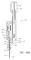
- FIG. 1is a perspective view of an apparatus for sealing a puncture through tissue including an introducer sheath, an occlusion member, a retraction assembly, and a source of liquid sealing compound.
- FIGS. 2A and 2Bare perspective views of the introducer sheath and occlusion member of FIG. 1 , showing a balloon on the occlusion member in collapsed and expanded states, respectively.
- FIGS. 3A and 3Bare cross-sectional details of a distal portion of the occlusion member shown in FIGS. 2A and 2B , respectively.
- FIG. 4is a side view of a hub subassembly shown on a proximal end of the occlusion member of FIGS. 2A and 2B .
- FIG. 5is a cross-sectional side view of the proximal hub subassembly of FIG. 4 , including a piston and spring therein and connected to inner and outer members of the occlusion member.
- FIG. 6is a perspective detail, showing a piston being attached to an inner member and received in a housing to provide the proximal hub subassembly shown in FIGS. 4 and 5 .
- FIGS. 7A-7Care perspective views of an expandable frame that may be provided on an occlusion member.
- FIG. 8Ais a perspective view of a switch for expanding and collapsing the expandable frame of FIGS. 7A-7C .
- FIG. 8Bis a detail of a pin-slot arrangement of the switch of FIG. 8A .
- FIG. 9is a cross-sectional view of the occlusion member, the introducer sheath assembly, and the retraction assembly of FIG. 1 .
- FIGS. 10A and 10Bare cross-sectional details of a lock mechanism of the retraction assembly of FIG. 1 in outward locked and inward actuated positions, respectively.
- FIGS. 11A-11Fare cross-sectional views of a percutaneous puncture communicating with a blood vessel showing a method for sealing the puncture, in accordance with the present invention.
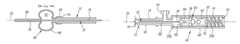
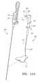
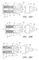
- FIG. 12Ais a perspective view of an alternative embodiment of an occlusion member, including an actuator switch for expanding and/or collapsing a balloon thereon.
- FIG. 12Bis a cross-sectional view of the occlusion member actuator switch of FIG. 12A .
- FIG. 12Cis an exploded perspective view of the occlusion member of FIG. 12A .
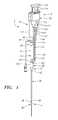
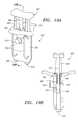
- FIG. 13is a cross-sectional view of a tensioner for supporting the occlusion member of FIGS. 12A and 12B .
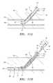
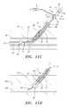
- FIGS. 14A and 14Bare perspective views, showing the occlusion member of FIGS. 12A and 12B being coupled to the tensioner of FIG. 13 .
- FIG. 15is a perspective view of a linear valve.
- FIG. 16Ais a front view of a syringe assembly connected to a linear valve, such as that shown in FIG. 15 , with the valve in a first position connecting the syringe assembly to vials or precursor polymer compounds.
- FIG. 16Bis a side view of the syringe assembly of FIG. 16A , with the linear valve in a second position connecting the syringe assembly to a “Y” fitting.
- FIGS. 17A-17Care end views of a revolver valve that may be connected to a syringe assembly, rotated into three different positions.
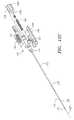
- FIG. 18Ais a perspective view of another embodiment of an apparatus for sealing a puncture through tissue, including a retraction assembly, an introducer sheath, and an occlusion member.
- FIGS. 18B and 18Care cross-sectional details of the apparatus of FIG. 18A .
- FIG. 19Ais a perspective view of an auto-injector device for delivering a sealing compound.
- FIG. 19Bis a cross-section of the auto-injector device of FIG. 19A , taken along line 19 B- 19 B.
- FIG. 19Cis an exploded perspective view of the auto-injector device of FIG. 19A .
- FIGS. 20A-20Fare cross-sectional views of another embodiment of an auto-injector device, including internal springs.
- FIGS. 1-6depict an exemplary embodiment of an apparatus 2 for sealing a puncture extending through tissue and/or communicating with a body lumen (not shown).
- the apparatus 2includes an occlusion member 4 carrying a balloon 80 or other expandable member, an introducer sheath assembly 6 slidable relative to the occlusion member 4 , a delivery device 8 for delivering sealing material through the introducer sheath assembly 6 , and a retraction assembly 10 for controlling movement of the introducer sheath assembly 6 relative to the occlusion member 4 .
- the introducer sheath assembly 6generally includes an outer sleeve or introducer sheath 90 including a proximal end 92 , a distal end 94 , and a housing 98 on the proximal end 92 defining a cavity 99 .
- the introducer sheath 90may be an elongate tubular member including a lumen 96 (not shown, see FIGS. 11A-11E ) that extends between the proximal and distal ends 92 , 94 .
- the introducer sheath 90terminates in a tapered distal tip 95 for facilitating advancing the introducer sheath 90 through a puncture.
- Exemplary materials for the introducer sheath 90may include plastics, such as polyamide, PEEK, nylon, PET, PEBAX, and polyethylene, metals, such as stainless steel, and nickel titanium, and/or composite materials.
- the housing 98may include a generally annular body 100 attached or otherwise coupled to the proximal end 92 of the introducer sheath 90 .
- the housing 98may include one or more side ports 102 that communicate with the cavity 99 and the lumen 96 of the introducer sheath 90 .
- a single side port 102is provided that may include a luer lock or other connector, e.g., to facilitate connecting tubing 106 and the like to the side port 102 .
- the housing 98may include a flange 104 or other connector (not shown) that may be used to couple the introducer sheath assembly 6 to the retraction assembly 8 , as described further below.
- the introducer sheath 90may be a conventional introducer sheath, such as those well known in the art.
- the introducer sheath assembly 6is configured for slidably receiving the occlusion member 4 therein, as described further below.
- the occlusion member 4may be inserted through the lumen 96 of the introducer sheath 90 such that the balloon 80 is disposed distally beyond the distal end 94 of the introducer sheath 90 .
- the introducer sheath assembly 6may be slidable proximally relative to the occlusion member 4 , e.g., to facilitate delivering sealing material around the occlusion member 4 , as shown in FIGS. 11A-11F and described further below.
- the occlusion member 4 and introducer sheath assembly 6may include cooperating detents, connectors, or other features (not shown) that may interact to limit relative movement of the introducer sheath assembly 6 relative to the occlusion member 4 .
- the introducer sheath assembly 4may be slidable along the occlusion member 4 , and the cooperating features may prevent the distal end 96 of the introducer sheath 90 from being moved closer to the balloon 80 than a desired minimum distance, e.g., not more than about five millimeters (5 mm), as explained further below.
- the housing 98may include one or more annular seals (not shown) that provide a fluid-tight seal around the outer member 12 (or other instruments, not shown, inserted into the introducer sheath assembly 6 ) yet allow the introducer sheath assembly 6 to slide along the outer member 12 .
- the seals 99may prevent the sealing compound from leaking out of the housing 98 , and instead the fluids may pass through the lumen 96 of the introducer sheath 90 , as described further below.
- the occlusion member 4is an elongate structure including an outer member 12 , an inner member 32 slidably coupled to the outer member 12 , and a hub subassembly 38 or other mechanism for biasing the inner member 32 relative to the outer member 12 .
- the balloon 80 or other expandable member(not shown) is carried by the occlusion member 4 , and preferably coupled to the inner and outer members 32 , 12 , as described more particularly below.
- the outer member 12may be an elongate tubular body including a proximal end 14 , a distal end 16 , and a lumen 18 extending therebetween (shown in FIGS. 3A , 3 B, and 5 ), thereby defining a longitudinal axis 20 .
- the outer member 12may be flexible, semi-rigid, or rigid, e.g., having a uniform or variable flexibility along its length.
- a proximal portion of the outer member 12may be substantially rigid, e.g., a section of hypotube (not shown), to facilitate advancing the occlusion member 4 through a tubular member, such as the introducer sheath assembly 6 .
- a lubricious coating(not shown) may be provided on the exterior of the outer member 12 .
- the distal end 16is substantially flexible such that the distal end 16 may curve, bend, prolapse, or otherwise conform substantially to the contour of a puncture and/or other body lumen (not shown) into which the distal end 16 is inserted.
- the distal end 16may include detents, seals, and/or other components (not shown) to facilitate cooperation with the introducer sheath assembly 6 .
- the distal end 16 of the outer member 12may have a size sufficient to be inserted into a relatively small puncture and/or body lumen.
- the distal end 16 (and possibly the remainder of the outer member 12 )may have an outer diameter between about 0.010-0.030 inch (0.25-0.75 mm), and less than about 0.020 inch (0.5 mm) in certain embodiments.
- the inner member 32may be an elongate body including a proximal end 34 (shown in FIGS. 5 and 6 ), and a distal end 36 . As best seen in FIGS. 3A and 3B , the inner member 32 may be slidably received within the lumen 18 of the outer member 12 such that the distal end 36 of the inner member 32 extends beyond the distal end 16 of the outer member 12 . Preferably, the inner member 32 is sufficiently small such that the inner member 32 may be received in the lumen 18 of the outer member 12 , yet accommodate fluid being delivered through the lumen 18 , i.e., along an exterior of the inner member 32 .
- the inner member 32may be a solid wire of nickel-titanium alloy (“Nitinol”), stainless steel, polymeric, and/or composite material having an outer diameter between about 0.003-0.020 inch (0.075-0.5 mm), and less than about 0.010 inch (0.25 mm) in certain embodiments.
- the inner member 32may include a lumen (not shown) for receiving a guidewire (not shown) therethrough, e.g., such that the occlusion member 4 may be advanced over a guidewire.
- the inner member 32may be biased to move distally relative to the outer member 12 , i.e., from a proximal position (such as that shown in FIG. 3B ) to a distal position (such as that shown in FIG. 3A ), e.g., to facilitate collapsing the balloon 80 .
- hub subassembly 38may be provided for biasing the inner member 32 relative to the outer member 12 .
- the hub subassembly 38may include a housing 40 extending proximally from the proximal end 14 of the outer member 12 and a piston 60 coupled to the proximal end 34 of the inner member 32 . As best seen in FIG.
- the housing 40may include a hollow adaptor end 42 , a side port 44 communicating with an interior 46 of the housing 40 , and a hollow cylinder 48 .
- the cylinder 48may include an outer wall 50 and a proximal end wall 52 , thereby defining a chamber 54 that communicates with the interior 46 of the housing 40 .
- the end wall 52may only partially enclose the chamber 54 or may substantially seal the chamber 54 , as explained further below.
- the adapter end 42 of the housing 40may be attached to the proximal end 14 of the outer member 12 such that the interior 46 of the housing 40 communicates with the lumen 18 of the outer member 12 .
- the adapter end 42may be attached to the proximal end 14 of the outer member 12 using an adhesive, an interference fit, mating threads, and/or other connectors, e.g., to substantially permanently attach the housing 40 to the proximal end 14 of the outer member 12 .
- the side port 44may communicate with the lumen 18 via the interior 46 of the housing 40 .
- fluid delivered into the side port 44may enter the lumen 18 as well as the chamber 54 of the cylinder 48 via the interior 46 of the housing 40 .
- the side port 44may include a connector, e.g., a luer lock connector, or a nipple (not shown) for connecting tubing or otherwise connecting a source of fluid or other inflation media to the side port 44 .
- a connectore.g., a luer lock connector, or a nipple (not shown) for connecting tubing or otherwise connecting a source of fluid or other inflation media to the side port 44 .
- a syringe filled with inflation mediae.g., saline, carbon dioxide, and the like
- a pump or other devicemay be provided for delivering fluid at a desired pressure and/or flow rate.
- the piston 60may be slidably received in the cylinder 48 , thereby dividing the chamber 54 into a proximal chamber 54 a and a distal chamber 54 b .
- the piston 60may include one or more seals 62 for providing a fluid-tight seal between the piston 60 and the side wall 50 of the cylinder 48 , while accommodating the piston 60 sliding within the chamber 54 .
- the piston 50may include a distal surface 66 that is exposed to fluid pressure within the distal chamber 54 b , and consequently to fluid pressure within the interior 46 of the housing 40 and/or within the lumen 18 of the outer member 12 .
- the proximal end 34 of the inner member 32may be coupled to the piston 60 , thereby coupling axial movement of the inner member 32 to axial movement of the piston 60 , as shown in FIG. 5 .
- the distal surface 66 of the piston 50may include an aperture 68 through which the proximal end 34 of the inner member 32 may be received.
- a compression spring or other mechanism 74may be provided in the proximal chamber 54 a of the housing 40 , e.g., for biasing the piston 60 away from the end wall 52 , i.e., towards the adapter end 42 of the housing 40 .
- the spring 74may apply an axial force against a proximal surface 76 of the piston 60 and the end wall 52 of the cylinder 48 .
- the spring constant of the spring 74may be selected to provide a desired biasing force.
- the proximal chamber 46 a of the cylinder 48may be filled with a compressible fluid, e.g., nitrogen, carbon dioxide, or air, that may be pressurized to a predetermined pressure to bias the piston 50 away from the end wall 44 .
- a compressible fluide.g., nitrogen, carbon dioxide, or air
- the pressure of the fluidmay exceed the predetermined pressure, thereby causing the piston 60 to move proximally and compress the fluid within the proximal chamber 46 a until the pressures within the chambers 46 a , 46 b are substantially equal to one another.
- an extension spring(not shown) may be provided in the distal chamber 54 b that may be coupled to the piston 60 and the cylinder 48 at the end near the side port 44 to bias the piston 60 distally.
- the hub subassembly 38may not include a biasing mechanism, e.g., no spring 74 or compressible fluid.
- movement of the piston 60may be controlled directly by the pressure and/or vacuum applied to inflate and/or deflate the balloon 80 , respectively.
- the pressure differential between the piston 60 and the balloon 80may initially cause the piston 60 to slide proximally, thereby applying a proximal tensional load to the inner member 32 while the balloon 80 is expanding.
- the negative pressure differential between the piston 60 and the balloon 80may initially cause the piston 60 to slide distally, thereby applying a distal compressive load to the inner member 32 while the balloon 80 is deflating.
- a desired pressure differentialmay be achieved by using a viscous fluid (i.e., a fluid more viscous than air) and/or by creating a restriction (not shown) within the lumen 18 distal to the side port 44 to delay the pressure from entering or exiting the balloon 80 .
- This pressure differentialmay be particularly important when inflating and/or deflating an everted balloon.
- a constriction(not shown) may be provided within the lumen 18 , e.g., between the side port 44 and the distal end 16 to cause the piston 60 to move before fluid is introduced into the balloon 80 .
- cooperating stopsmay be provided for preventing over-inflation of the balloon 80 , as described in application Ser. No. 10/454,362 incorporated by reference herein.
- the balloon 80is carried on the distal end 16 of the outer member 12 .
- the balloon 80may be expandable from a collapsed state (shown in FIGS. 2A and 3A ) to an expanded state (shown in FIGS. 2B and 3B ) when a fluid or other inflation media (not shown) is introduced into an interior 82 of the balloon 80 .
- a fluid or other inflation medianot shown
- other expandable memberse.g., a mechanically expandable or self-expanding member (not shown) may be provided instead of the balloon 80 , as described further below.
- the balloon 80may be formed from a flexible, substantially inelastic material, e.g., a nonelastomeric material, such as PET, nylon, polyethylene, polyurethane, PEBAX, and the like, that may provide a substantially noncompliant or semi-compliant balloon 80 that may expand to a predetermined size once a minimum pressure is introduced into the interior 82 .
- a flexible, substantially inelastic materiale.g., a nonelastomeric material, such as PET, nylon, polyethylene, polyurethane, PEBAX, and the like
- the size of the balloon 80 in the expanded statemay be fixed.
- the balloon 80may be formed from an elastic material, such that the size of the balloon 80 in the expanded state is dependent upon the pressure or volume of fluid delivered within the interior 82 , as is known in the art.
- the balloon 80may include a proximal end 84 , a distal end 86 , and an expandable intermediate section 88 defining the interior 82 of the balloon 80 .
- the proximal end 84 of the balloon 80may be attached to the distal end 16 of the outer member 12
- the distal end 86 of the balloon 80may be attached to the distal end 36 of the inner member 32 .
- the interior 82 of the balloon 80may communicate with the lumen 18 of the outer member 12 .
- the proximal end 84 of the balloon 80may extend proximally, replacing all or a portion of the outer member 12 (not shown).
- the proximal end 84 of the balloon 80may be laminated or drawn over a stiffer proximal shaft (not shown).
- the proximal end 84 of the balloon 80may overlie and be attached to the distal end 16 of the outer member 12 , e.g., using an adhesive, sonic welding, crimping, an interference fit, and the like.
- the distal end 36 of the inner member 32may extend through the interior 82 of the balloon 80 (i.e., through the intermediate section 88 ), and at least partially into the distal end 86 of the balloon 80 , optionally extending an entire length of the distal end 86 of the balloon 80 .
- the distal end 86 of the balloon 80may be attached to the distal end 36 of the inner member 32 , e.g., using an adhesive, sonic welding, crimping, a compressive sleeve, an interference fit, and the like.
- An annular band of materiale.g., polyimide or PET, may be attached or otherwise provided over the proximal and distal ends 84 , 86 of the balloon 80 to attach the ends 84 , 86 to the outer and inner members 12 , 32 .
- a bandmay be provided around the proximal end 84 of the balloon 80 to prevent the balloon 80 from delaminating from the outer member 12 when the balloon 80 is inflated.
- the distal end 86 of the balloon 80may extend beyond the distal end 36 of the inner member 32 , e.g., to provide a floppy or otherwise substantially atraumatic tip for the occlusion member 4 .
- the distal end 86 of the balloon 80may have a length of at least about fifty millimeters (50 mm), and the distal end 36 of the inner member 32 may only extend about twenty millimeters (20 mm) or less into the distal end 86 of the balloon 80 .
- the distal end 36 of the inner member 32may extend beyond the distal end 86 of the balloon 80 , and may terminate in a substantially atraumatic tip (not shown).
- the atraumatic tipmay mimic the behavior of a standard “J”-tip guide wire, e.g., a 0.035 inch or 0.038 inch wire, commonly used with introducer sheaths.
- the balloon 80may conform substantially to the diameter of the outer member 12 .
- the proximal and distal ends 84 , 86 of the balloon 80 and the distance between the distal ends 16 , 36 of the outer and inner members 12 , 32are such that the balloon 80 is under slight axial tension in the collapsed state, thereby minimizing risk of the balloon 80 expanding, kinking, or otherwise increasing in cross-section and/or catching on anything contacted by the balloon 80 .
- the balloon 80is expanded to the expanded state, shown in FIGS. 2B and 3B , by introducing inflation media (not shown) into the lumen 18 of the outer member 12 , and consequently into the interior 82 of the balloon 80 .
- inflation medianot shown
- the fluidwhen fluid is introduced into the lumen 18 , the fluid initially enters the interior 46 of the housing 40 (not shown, see FIGS. 4 and 5 ), and consequently into the distal chamber 54 b of the cylinder 48 (also not shown, see FIGS. 4 and 5 ).
- the piston 60may move proximally within the cylinder 48 , thereby pulling the inner member 32 proximally.
- the intermediate section 88 of the balloon 80may have a length L C
- the intermediate section 88may have a length L E that is substantially shorter than L C
- the balloon 80may have a diameter between about four and ten millimeters (4-10 mm), and a length L E between about two and ten millimeters (2-10 mm).
- the balloonmay have a diameter of about six millimeters (6 mm) at thirty pounds per square inch (30 psi) internal pressure and a length L E of about four millimeters (4 mm).
- the balloon 80at least partially everts in the expanded state, i.e., the length L E of the balloon 80 may be substantially smaller than the diameter.
- the proximal and distal ends 84 , 86 of the balloon 80may become sufficiently close to one another that they at least partially enter the interior 82 of the balloon 80 , as shown in FIG. 3B , thereby defining a toroidal shape.
- This everted configuration(which may also be referred to as a “bagel balloon” configuration) may facilitate creating hemostasis within a puncture in a wall of a body lumen (not shown) while allowing increased fluid flow and/or vessel perfusion to continue along the body lumen, as explained further below.
- the cross-section of the distal chamber 54 b of the cylinder 48may be substantially larger than a cross-section of the lumen 18 of the outer member 12 .
- the pressuremay impose a proximal force on the distal surface 66 of the piston 60 . Because of the relatively large area of the distal chamber 54 b , fluid may flow easily into the distal chamber 54 b before flowing down the lumen 18 into the interior of the balloon 80 .
- a proximal forcemay be applied to the piston 60 before or as the balloon begins to expand, thereby shortening the balloon 80 before or as it expands towards the expanded state.
- the fluid from the distal chamber 54 b of the cylinder 48may be removed before fluid is drawn up the lumen 18 and the balloon 80 begins to collapse. The resulting vacuum may pull the piston 60 distally, causing the balloon 80 to elongate towards its collapsed length L C before or as the balloon collapses towards the collapsed state.
- This featuremay be particularly useful for ensuring that the balloon 80 is collapsed to as small a profile as possible when the balloon 80 is collapsed from the expanded state to the collapsed state, e.g., to minimize disruption of any sealing compound deposited in the puncture as the balloon 80 is withdrawn, as explained elsewhere herein.
- other expandable membersmay be provided on the distal ends 16 , 36 of the outer and/or inner members 12 , 32 .
- a balloonmay be provided that includes multiple chambers or “lobes” (not shown). Each lobe may be connected to the lumen 18 within the outer member 12 such that inflation media may enter each lobe to expand the balloon into a desired shape.
- the occlusion member 4may include multiple lumens (not shown) that communicate with one or more lobes such that the lobes may be independently expanded, if desired.
- the lobesmay expand away from one another transversely relative to the longitudinal axis 20 , thereby defining a relatively flat annular or “flower” configuration that may provide a substantially fluid-tight seal, yet allow perfusion to continue along a vessel, similar to the apparatus and methods described further below.
- mechanically expandable membersmay be provided, rather than fluid-expandable members.
- an expandable frame(not shown) may be coupled to the distal ends 16 , 36 of the outer and inner members 12 , 32 that may be expanded as the inner member 32 is directed proximally relative to the outer member 12 .
- a nonporous membranemay cover or otherwise be connected to the frame such that the membrane is expanded with the frame, thereby providing a relatively flat annular member that may be used to provided temporary hemostasis during delivery of a sealing compound, as described further below.
- Exemplary frames and membranes that may be used in conjunction with embodiments of the inventionare described in U.S. Pat. Nos. 5,782,860, 5,922,009, 6,056,769, and 6,464,712, the disclosures of which are expressly incorporated by reference herein.
- FIGS. 7A-7Cshow an exemplary embodiment of an expandable frame 180 that may be provided on an occlusion member 4 .′
- a nonporous membrane 189 coupled to the frame 180is shown in phantom, while in FIGS. 7A and 7B , the nonporous membrane 189 is omitted for convenience.
- the membrane 189may cover all or a portion of the frame 180 .
- the membrane 189may only cover a proximal portion of the frame 180 .
- the frame 180may be created by forming a plurality of longitudinal slits 182 in a tube, e.g., a Nitinol tube, using known procedures, such as laser cutting, to create struts 184 therebetween. Ends 186 , 188 of the frame 180 may be coupled to respective distal ends 16 ,′ 36 ′ of the outer and inner outer members 12 ,′ 32 ,′ similar to the ends of the balloon 80 described above.
- a tubee.g., a Nitinol tube
- the struts 184 created by the slits 182may buckle and expand transversely, to expand the membrane 189 .
- the slits 182are formed to facilitate buckling of the struts 184 .
- an intermediate portion 182 a of the slits 182may be widened to provide a weak point 184 a at which the struts 184 may buckle.
- the slits 182may be curved at the intermediate portion 182 a , e.g., defining a portion of a sinusoidal wave (not shown), to further control buckling of the struts 184 , and/or to provide strain relief.
- the frame 180 and membrane 184may be collapsed again by directing the inner member 32 ′ distally relative to the outer member 12 .′
- an actuatormay be provided on the occlusion member 4 .′
- a piston-cylinder arrangementmay be provided on the proximal end 14 ′ of the outer member 12 ′ to direct the inner member 32 ′ proximally and/or distally when a fluid is directed into the cylinder.
- a mechanical switch 38 ′may be provided, such as that shown in FIGS. 8A and 8B .
- An outer housing 40 ′may be coupled to the proximal end 14 ′ of the outer member 12 ,′ and a piston 60 ′ coupled to the inner member 32 ′ and slidably disposed within the housing 40 .
- a pin 61 ′may be coupled to the piston 60 ′ that extends through a “C” or “S” shaped slot 41 ′ in the housing 40 .
- horizontal portions of the slot 41 ′may correspond to the proximal and distal positions in which the frame 182 (not shown, see FIGS. 7A-7C ) is expanded and collapsed, respectively.
- the pin 61 ′may be slid horizontally out of one of the proximal and distal positions and moved along the slot 41 ′ to the other position.
- a spring or other mechanismmay be provided for biasing the piston 60 ′ distally or proximally, e.g., an extension spring 74 ′ may be provided for biasing the frame 180 towards the collapsed state, similar to the fluid-activated mechanism described above.
- the expandable framemay be biased to the expanded state, and a cover, e.g., a catheter, sheath, sleeve, and the like (not shown), may be provided for constraining the expandable frame in the collapsed state.
- a covere.g., a catheter, sheath, sleeve, and the like (not shown)
- the struts of the expandable framemay be provided from a shape memory and/or superelastic material, e.g., Nitinol, that may be heat treated to the expanded state.
- the covermay extend along the outer member of the occlusion member, e.g., from the expandable frame towards the proximal end of the occlusion member.
- the covermay be directed over the expandable frame to resiliently force the struts to collapse towards the collapsed state.
- the occlusion membermay be inserted into a puncture, e.g., through a delivery sheath or other tubular member, as described elsewhere herein.
- the covermay be at least partially retracted to expose the expandable frame, whereupon the struts may automatically expand towards the expanded state.
- the coverWhen it is desired to remove the occlusion member, the cover may be advanced back over the expandable frame to collapse the struts.
- the strutsmay be sufficiently resilient that the occlusion member may be removed without covering the expandable frame such that the struts contact the delivery sheath and collapse as they are drawn into the delivery sheath as the occlusion member is withdrawn.
- FIGS. 12A-12Canother embodiment of an occlusion member 204 is shown. Similar to the previous embodiments, the occlusion member 204 includes an outer member 212 , an inner member 232 slidably coupled to the outer member 212 , a hub subassembly 238 (shown in FIG. 12B ) for biasing the inner member 232 relative to the outer member 212 , and a balloon or other expandable member 280 (shown expanded in FIGS. 12A and 12C ) coupled to the inner and outer members 232 , 212 .
- a hub subassembly 238shown in FIG. 12B
- a balloon or other expandable member 280shown expanded in FIGS. 12A and 12C
- the hub subassembly 238is self-contained, rather than requiring a syringe or other source of inflation media for expanding the balloon 280 , e.g., to improve ease of use and/or allow single user operability.
- the outer member 212may be an elongate tubular body including a proximal end 214 , a distal end 216 , and a lumen 218 extending between the proximal and distal ends 214 , 216 , thereby defining a longitudinal axis 220 .
- the inner member 232may be an elongate wire or other body including a proximal end 234 and a distal end 236 . As best seen in FIG. 12B , the inner member 232 is slidably received within the lumen 218 of the outer member 212 such that the distal end 236 of the inner member 232 extends beyond the distal end 216 of the outer member 212 .
- the balloon 280is coupled to the distal ends 216 , 236 of the outer and inner members 212 , 232 such that an interior of the balloon 280 communicates with the lumen 218 of the outer member 212 , similar to the embodiments described above.
- the inner member 232is biased to move distally relative to the outer member 212 , i.e., from a proximal position to a distal position (similar to the arrangement shown in FIGS. 3 A and 3 B, e.g., to facilitate collapsing the balloon 280 ).
- the hub subassembly 238may bias the inner member 232 relative to the outer member 212 , similar to the previous embodiments.
- the hub subassembly 238includes a housing 240 extending proximally from the proximal end 214 of the outer member 212 and a piston 243 coupled to the proximal end 234 of the inner member 232 .
- the piston 243is biased distally within a chamber 242 of the housing 240 by a spring 274 .
- the housing 240also includes an actuator, such as a depression switch 248 , and a passage 244 connecting the chamber 242 with a reservoir 246 .
- the switch 248may include a handle or button 248 a and a piston 248 b extending from the handle 248 a into the reservoir 246 .
- the reservoir 246may be filled with fluid, thereby allowing fluid to flow into and out of the chamber 242 and the lumen 218 of the outer member 212 .
- the reservoir 246may be filled via valve 247 from a syringe or other source of inflation media (not shown), similar to the embodiments described above, to cause the balloon 280 to expand and collapse when the switch 247 is activated and deactivated, respectively.
- the reservoir 246is filled sufficiently with the piston 243 in its distal position and the balloon 280 collapsed without causing the piston 243 to move distally and/or the balloon 280 to expand.
- the switch 248may be depressed to direct the piston 248 b into the reservoir 246 to force fluid from the reservoir 246 into the chamber 242 and lumen 218 , thereby directing the piston 243 proximally as the balloon 280 expands, similar to the previous embodiments.
- the switch 248is a depression switch that may be depressed distally to expand the balloon 280 .
- a spring 249 coupled to the switch 248may direct the switch 248 proximally to its original position, thereby drawing fluid back into the reservoir 246 from the chamber 242 and lumen 218 , and collapsing and extending the balloon 280 as the piston 243 moves distally.
- switchese.g., rotation switches and the like (not shown) may be provided instead of the depression switch 248 .
- other piston/spring arrangementsmay be provided in the housing 240 , similar to the previous embodiments.
- the occlusion member 204may include a cover 239 for concealing and/or protecting the internal components of the housing 240 , actuator, etc.
- the cover 239may include sets of grooves for connecting the occlusion member 204 to a tensioner, such as that shown in FIG. 13 .
- a window 245may be provided in the cover 239 for observing the piston 243 within the housing 240 .
- the window or covermay include graduated markings (not shown) indicating a pressure level, and the piston 243 may include a visual marker (also not shown).
- the visual marker on the piston 243may align with the graduated markings along the window 245 , thereby indicating the pressure within the housing 240 . This may facilitate initially filling the reservoir 246 during set-up.
- the graduated markingsmay indicate the position of the piston and the internal pressure as the switch is ratcheted through the multiple positions.
- the delivery device 8may include a dual syringe assembly 130 that includes two components of a sealing compound, a “Y” fitting 140 , and a static mixer 110 .
- the syringe assembly 130may include a pair of syringe barrels 132 including access ports or outlets 136 and a plunger assembly 133 slidable into the barrels 132 to cause the components therein to be delivered through the outlets 136 .
- the plunger assembly 133includes a pair of plungers 134 that are coupled to one another yet are received in respective barrels 132 . Thus, both plungers 134 may be manually depressed substantially simultaneously to deliver the components in the syringe barrels 132 out together.
- the plunger assembly 133may also include a trigger that may actuate the retraction assembly 10 , as described further below.
- the triggermay be a shaft or piston 135 that extends distally between the plungers 134 .
- the shaft 135may extend distally between the barrels 132 .
- the “Y” fitting 140may include proximal sections 142 that communicate with a single distal section 144 .
- the “Y” fitting 140may be connectable to outlets 136 of the syringes 132 such that the components ejected out of the syringes 132 may mix before being delivered into the side port 102 of the introducer sheath assembly 6 .
- the proximal and distal sections 142 , 144may include connectors, e.g., luer lock connectors and the like (not shown), for connecting with outlets 136 of the syringes 132 and/or with the mixer 110 , the tubing 106 , and/or the side port 102 of the introducer sheath assembly 6 .
- the “Y” fitting 140may have a variety of shapes, depending upon the performances properties and/or manufacturing parameters, and should not be restricted to a particular shape, such as a true “Y” shape, but may still be referred to as a “Y” fitting.
- the mixer 110may be a tubular body including vanes or other internal structures (not shown) that enhance the components mixing thoroughly together as they pass therethrough. Similar to the “Y” fitting 140 , the mixer 110 may include connectors (not shown) for releasably or substantially permanently connecting the mixer 110 to the “Y” fitting 140 , tubing 106 , and the like.
- a liquid precursor polymer compoundis provided in each syringe barrel 132 of the syringe assembly 130 that, when mixed together, may be activated to form a hydrogel. Additional information on hydrogels and systems for delivering them are disclosed in U.S. Pat. Nos. 6,152,943, 6,165,201, 6,179,862, 6,514,534, and 6,379,373, and in co-pending application Ser. No. 09/776,120 filed Feb. 2, 2001, 10/010,715 filed Nov. 9, 2001, and 10/068,807 filed Feb. 5, 2002. The disclosures of these references and any others cited therein are expressly incorporated by reference herein.
- the syringe assembly 130may include one or more valves coupled to the outlets 136 of the syringes 132 .
- a valvemay be used to connect the syringe barrels 132 to a source of sealing components for introducing the components into the syringe barrels 132 during set-up before sealing a puncture created during a procedure.
- the valvemay be closed to substantially seal the outlets 136 , e.g., to temporarily store the components during a procedure.
- the valvemay be used to connect the syringes 132 to the “Y” fitting 140 or other delivery line to allow the components to be delivered into a puncture.
- the valve 310generally includes a piston or other member 314 slidable within a housing 312 .
- the housing 312includes two sets of side ports 316 a , 316 b that may be aligned with lumens 318 extending through the piston 314 when the piston 314 is in first and second positions, respectively.
- the lumens 318may be coupled to the outlets of respective syringe barrels of a syringe assembly (not shown) at end ports 320 .
- the linear valve 310may be coupled to the delivery device 308 , e.g., by tubing 324 .
- outlets 336 of syringe barrels 332may be coupled to the end ports 320 (shown in FIG. 15 ) by tubing 324 c .
- the first set of side ports 316 amay be connected to a source of sealing components, such as vials 322 (not shown), by tubing 324 a .
- the second set of ports 316 bmay be coupled to inlets 432 of a “Y” fitting 339 by tubing 324 b.
- the valve 310may be placed in the first position shown in FIG. 16A , e.g., by directing actuator button 350 proximally.
- Sealing compounde.g., precursor polymer components
- the syringe barrels 332may include liquid solvent and/or buffer solution
- the vials 322may include precursor polymer components in powder or other solid form.
- the valve 310may then be moved to a closed position, e.g., an intermediate position such that the lumens 318 do not communicate with either of the sets of side ports 316 a , 316 b .
- the vials 322e.g., along with the entire delivery device 308 ) may then be shaken to mix and/or reconstitute the precursor polymer compounds into liquid form.
- the valve 310may then be returned to the first position, and the plunger assembly 133 may be withdrawn from the syringe barrels 332 in order to draw a desired amount of the reconstituted precursor components into the barrels 332 .
- the barrels 332may be loaded only with a predetermined amount of the components based upon an approximation of the volume to be delivered into a puncture being sealed.
- the barrels 332may include volumetric graduation indicators that may guide a user to draw the predetermined amount of sealing components into the barrels 332 .
- valve 310When it is time to deliver the sealing components, the valve 310 may be placed in the second position shown in FIG. 16B , e.g., by directing the actuator button 350 distally. In this position, the outlets 336 of the syringes 332 communicate with the “Y” fitting 340 , allowing the sealing compound to be delivered via the tubing 324 c , end ports 320 , lumens 318 , side ports 316 b , and tubing 324 b .
- the “Y” fitting 230may coupled to a delivery line (not shown), as described elsewhere herein for delivering the sealing compound into a puncture.
- valve 310may facilitate a user filling the syringes 332 with a desired volume of sealing compound from a vial 322 or other source with the valve 310 in a loading position, including allowing mixing and/or reconstituting sealing components. During use, the valve 310 may simply be moved to a delivery position to allow the sealing compound to be delivered. In addition, if desired, the valve 310 may have a third position where the lumens 318 do not communicate with either of the side ports 316 a , 316 b , thereby substantially eliminating the risk of precursor polymer materials escaping from the syringes 332 and/or mixing prematurely.
- Such a valve 310may be convenient to use for a manually infected system, such as those described above.
- such valvesmay be particularly convenient for an auto-injector system, i.e., a system that automatically delivers a sealing compound once the system is triggered or otherwise activated, as described further below.
- FIGS. 17A-17Cshow an embodiment of a revolver valve 410 that may be provided, including a valve body 414 (shown in phantom) rotatable within a housing 412 .
- the valve 410includes ports 420 (shown in phantom) that may be connected to syringes of a delivery device (not shown), and first and second sets of ports 416 a , 416 b that may be connected to respective vials and a “Y” fitting (also not shown), respectively, e.g., by tubing (not shown), similar to the previous embodiment.
- Internal lumens or passages (not shown) in the body 414communicate with the ports 420 and may selectively communicate with the ports 416 a or 416 b , depending upon the position of the body 414 relative to the housing 412 .
- the ports 420do not communicate with either of the other ports 416 a , 416 b , and the valve 410 is closed or off.
- the ports 420communicate with the ports 416 a , allowing syringes to be filled from vials, as described above.
- the ports 420communicate with the ports 416 b , creating a passage through which the precursor polymers may be injected from syringes through a “Y” fitting and into a patient (not shown), as described above.
- FIGS. 1 and 9an embodiment of a retraction assembly 10 is shown that generally includes a housing 112 to which the occlusion member 4 may be secured, a shaft 114 slidably coupled to the housing 112 and the introducer sheath assembly 6 , and a lock/release mechanism 116 for controlling movement of the shaft 114 relative to the housing 112 .
- the housing 112may include one or more connectors (not shown) for securing the occlusion member 4 to the housing 112 .
- the housing 112may include a recess for receiving the hub subassembly 38 of the occlusion member 4 therein and/or one or more catches, detents, and the like (not shown) for releasably or substantially permanently securing the occlusion member 4 thereto.
- the occlusion member 4may be incorporated into or otherwise substantially permanently attached to the retraction assembly 10 .
- the introducer sheath assembly 6may be slidably disposed over the occlusion member 4 before or after the occlusion member 4 is secured to the retraction assembly 10 .
- the occlusion member 4may be mounted to the retraction assembly 10 during manufacturing such that the shaft 114 extends distally adjacent to the outer member 12 of the occlusion member 4 .
- the shaft 114 and the introducer sheath assembly 6may include one or more connectors for releasably or substantially permanently connecting the shaft 114 to the introducer sheath assembly 6 .
- a distal end 121 of the shaft 114may include a hook, tab, or other element (not shown) that may be received in a hole or pocket (also not shown) in the flange 104 on the introducer sheath assembly 6 .
- the balloon 80 of the occlusion member 4may be inserted into the housing 98 and advanced distally through the lumen 96 of the introducer sheath 90 until the balloon 80 extends beyond the distal end 94 of the introducer sheath 90 .
- the distal end 121 of the shaft 114may then be attached to the flange 104 .
- axial movement of the introducer sheath assembly 6may be coupled to axial movement of the shaft 114 .
- the apparatus 2may include a cover (not shown) for concealing the various components of the retraction assembly 10 , along with the components of the occlusion member 4 and/or introducer sheath assembly 6 to which users do not need access.
- the housing 112 of the retraction assembly 10may include a passage 118 therein that extends substantially parallel to the longitudinal axis 20 .
- a proximal end 120 of the shaft 114may be slidably received in the passage 118 , while the distal end 121 of the shaft 114 may be coupled to the introducer sheath assembly 6 , e.g., to the flange 106 , as described above.
- the shaft 114may be biased to move within the passage 118 to bias axial movement of the introducer sheath 90 coupled to the retraction assembly 10 .
- a compression spring 122 or other elementmay be provided in the passage 118 for biasing the shaft 114 proximally relative to the housing 112 .
- the lock/release mechanism 116may include a lock member 124 that is disposed within the housing 112 and that is movable transversely relative to the passage 118 .
- a spring or other mechanism(not shown) may be provided for biasing the lock member 124 outwardly such that a release button 126 of the lock member 124 extends through an opening 128 in the housing 112 .
- the release button 126may include a sloped outer proximal surface 126 a , e.g., to convert an axial force from the piston 135 of the plunger assembly 130 into a transverse force for moving the lock member 124 inwardly.
- the lock member 124may include connectors for releasably securing the shaft 114 at one or more positions within the passage 118 .
- the lock member 124may include an aperture 125 through which a portion of the shaft 114 may extend.
- the lock member 124may engage the shaft 114 to prevent the shaft 114 from moving axially within the passage 118 .
- a portion of the lock member 124may simply frictionally engage the shaft 114 .
- the lock member 124 and shaft 114may include one or more cooperating detents (not shown) that engage one another when the lock member 124 is in the outer locked position.
- the shaft 114When the lock member 124 is pushed inwardly, e.g., when the release button 126 is depressed (shown in FIG. 10B ), the shaft 114 may be released from the lock member 124 and free to move axially within the passage 118 . Because of the bias provided by the spring 122 , the shaft 114 may move proximally within the passage 118 until the proximal end 116 of the shaft 114 reaches the end of the passage 118 or encounters a stop (not shown), preventing further proximal movement.
- the introducer sheath 90may be secured relative to the outer member 12 .
- the distal end 94 of the introducer sheath 90may be located a predetermined distance proximal to the balloon 80 of the occlusion member 4 , as shown in FIG. 1 .
- the introducer sheath 90is directed proximally, thereby moving the distal end 94 of the introducer sheath 90 away from the balloon 80 of the occlusion member 4 (not shown).
- the distance that the introducer sheath 90 is moved by the shaft 114preferably corresponds generally to the length of a puncture or other tract through tissue that is being sealed by the apparatus 2 .
- the lock member 124is preferably released automatically as sealing compound is being delivered from the delivery device 8 .
- the delivery device 8includes piston 135 extending from the plunger assembly 133 .
- the piston 135is preferably aligned axially with the release button 126 extending from the housing 112 of the retraction assembly 10 .
- the piston 135may contact the sloped proximal surface 126 a of the release button 126 .
- the piston 135may bear against the sloped proximal surface 126 a , thereby directing the release button 126 and, consequently, the lock member 124 inwardly to release the shaft 114 .
- the distance between the piston 135 and the release button 126is predetermined such that the lock member 124 is released at a desired time during the stroke of the plunger assembly 133 .
- the components in the syringe barrels 132may be injected through the “Y” fitting 140 , into the housing 98 of the introducer sheath assembly 6 , and through the lumen 96 of the introducer sheath 90 .
- the lock member 124may be released to allow the introducer sheath 90 to retract proximally, thereby filling a puncture within which the introducer sheath 90 is disposed with the sealing material.
- FIG. 18A-18Canother embodiment is shown of an apparatus 502 that includes an occlusion member 504 , an introducer sheath 506 , a delivery device 508 , and a retraction assembly 510 .
- the occlusion member 504may be releasably or substantially permanently attached to the retraction assembly 510 , similar to the previous embodiments.
- the introducer sheath 506may be a conventional introducer sheath or may be similar to other embodiments described herein.
- the delivery device 508may be a dual-syringe assembly, including manual injection or automatic injection, also similar to other embodiments described herein.
- the retraction assembly 510may include a housing 512 to which the occlusion member 504 may be secured, a shaft 514 slidably coupled to the housing 512 , and a lock/release mechanism (not shown) for controlling movement of the shaft 514 relative to the housing 512 , e.g., based upon use of the delivery device 508 .
- the occlusion member 504may include an outer member 512 and a balloon 580 carried on a distal end 516 of the outer member 512 .
- the occlusion member 504may include one or more of the other components described above with respect to other embodiments.
- the retraction assembly 510includes a delivery sheath 530 that surrounds and is slidable relative to a proximal portion of the outer member 516 .
- the delivery sheath 530includes a distal end 532 having a size and shape allowing the delivery sheath 530 to be inserted into a lumen 507 of the introducer sheath 506 .
- the delivery sheath 530is coupled to the shaft 514 such that axial movement of the delivery sheath 530 corresponds to movement of the shaft 514 .
- a distal end 515 of the shaft 514 and a proximal end 531 of the delivery sheath 530may include cooperating connectors (not shown) for releasably or substantially permanently coupling the shaft 514 and the delivery sheath 530 to one another, similar to the connectors described above for the shaft 114 and introducer sheath assembly 6 shown in FIG. 1 .
- each detent 534is a strip of spring material, e.g., a pseudoelastic and/or superelastic material, such as stainless steel or Nitinol, that has a fixed end attached to the delivery sheath 530 , and a free end 534 a formed into a loop.
- both ends of the detentmay be fixed, yet define a loop (not shown). Because of the elasticity of the spring material, the detent 534 may be collapsed against the delivery sheath 530 , e.g., if the loop is unrolled or collapsed, yet may resume its looped shape when any external force is removed.
- the introducer sheath 506may include a housing 550 defining a cavity 552 and including a side port 554 communicating with the cavity 552 and, consequently, with the lumen 507 of the introducer sheath 506 .
- the housing 550may also include one or more seals (not shown) for substantially sealing the cavity 552 , yet allowing one or more instruments, e.g., the occlusion member 504 and/or the delivery sheath 530 to be inserted into the lumen 507 .
- the detents 534may contact the housing 550 , causing the free ends 534 a to unroll as the detents 534 enter the housing 550 . Once the detents 534 are located completely within the cavity 552 , the free ends 534 a may resume their looped shape. Alternatively, if both ends of the detents are fixed, the detents may simply collapse as they are directed into the housing 550 and then resilient return to their looped shape once located within the cavity 552 .
- the detents 534may contact the wall of the housing 550 , preventing the delivery sheath 530 from being removed easily from the introducer sheath 530 .
- proximal movement of the delivery sheath 530will cause proximal movement of the introducer sheath 506 .
- detents 534are shown opposite one another on the delivery sheath 530 , it will be appreciated that one or more detents may be provided at one or more locations around the delivery sheath 530 for coupling to the introducer sheath 506 .
- additional connectorsmay be provided, such as ramped tabs and the like instead of the spring loops described above.
- the delivery sheath 530may also include an annular seal 536 adjacent to, and preferably, distal to the detents 534 .
- the seal 536may be a solid mass of resilient material, e.g., plastic, foam rubber, and the like, e.g., formed into a tapered wedge shape contoured to provide sufficient interference with the interior of the housing 550 .
- the seal 536may be a balloon or other membrane that may be filled with a desired volume of fluid, e.g., saline, nitrogen, carbon dioxide, and the like.
- the seal 536may compress sufficiently to allow the seal 536 to enter the cavity 552 .
- the seal 536may substantially engage an interior of the housing 550 and/or introducer sheath 506 .
- the seal 536may substantially seal the lumen 507 of the introducer sheath 506 from fluid flow distally between the delivery sheath 530 and the introducer sheath 506 .
- One advantage of such a seal 536is that it may allow a delivery sheath 530 having a fixed size to be inserted into a variety of sized introducer sheaths, while still substantially sealing the lumen of the introducer sheaths.
- the delivery sheath 530may include one or more openings 538 (a pair being shown) adjacent the detents 534 and communicating with a lumen 540 extending to the distal end 532 of the sheath 530 .
- the delivery sheath 530may have sufficient length such that, when the delivery sheath 530 is fully received in the introducer sheath 506 , the distal end 532 may extend beyond the distal end (not shown) of the introducer sheath 506 .
- Sealing compoundmay be injected into the side port 554 of the housing 550 using any of the delivery devices described herein. With the lumen 507 of the introducer sheath 506 sealed by the seal 536 , the injected sealing compound may be forced through the openings 538 into the lumen 540 and out the distal end 532 of the delivery sheath 530 .
- the delivery sheath 530 and the occlusion member 4may include cooperating detents, connectors, or other features (not shown) for limiting distal movement of the delivery sheath 530 relative to the occlusion member 4 .
- the delivery sheath 530may be movable distally until the cooperating features contact one another, e.g., such that the distal end 532 of the delivery sheath 530 is located a minimum distance from the balloon 80 of the occlusion member 4 , e.g., at least about five millimeters (5 mm).
- Such featuresmay prevent the delivery sheath 530 from being directed against or too close to the balloon 80 , which may increase the risk of sealing material being delivered into the vessel (not shown), as explained further below.
- the length of the delivery sheath 530may be reduced to have a relatively short length compared to the introducer sheath 506 , e.g., sufficient to engage the detents 534 within the housing 550 .
- the sealing compoundwhen sealing compound is injected into the side port 554 , the sealing compound may pass along the lumen 507 of the introducer sheath 506 and out its distal end (not shown).
- a shortened delivery sheathmay simply be a connector for coupling movement of the introducer sheath 506 to the retraction assembly 510 .
- a sheathsimilar to the delivery sheath 530 described above, may be utilized in an embodiment without a retraction assembly.
- the delivery sheathmay include an enlarged handle on its proximal end to facilitate manual manipulation of the delivery sheath once it is coupled to the introducer sheath.
- the delivery sheathmay be inserted into the introducer sheath until the detents enter the housing of the introducer sheath, thereby coupling subsequent movement of the introducer sheath to the delivery sheath.
- the delivery sheathmay include a seal in its proximal end, allowing an occlusion member to be inserted into the delivery sheath, and consequently, through the introducer sheath, using the methods described elsewhere herein.
- the delivery sheathmay be drawn proximally while sealing compound is being delivered through the introducer sheath, thereby manually retracting the introducer sheath and at least partially filling a puncture with sealing compound.
- the passageis a percutaneous puncture 190 extending from a patient's skin 192 to a blood vessel or other body lumen 194 .
- the vessel 194may be a peripheral artery, e.g., a femoral artery, a carotid artery, and the like. It will be appreciated that the apparatus and methods in accordance with the various embodiments of the present invention may be used to seal other passages within a patient's body.
- the introducer sheath 90 of the introducer sheath assembly 6may be placed within the puncture 190 such that the distal end 94 is disposed within the vessel 192 without the other components of the apparatus 2 .
- the introducer sheath 90may be introduced within the puncture 190 using conventional methods, such as those used to insert known introducer sheaths.
- a separate introducer sheath(not shown) may be inserted into the puncture 190 using known procedures.
- One or more instrumentsmay be advanced through the introducer sheath 90 (or separate introducer sheath) and into the vessel 194 , e.g., to perform one or more diagnostic and/or therapeutic procedures within the patient's body.
- the one or more instrumentsmay include catheters, e.g., balloon catheters, stent delivery catheters, imaging catheters, and the like, guidewires, and/or other devices.
- any instrumentsmay be removed and the puncture 190 may be sealed using an apparatus, such as that shown in FIGS. 1-6 and described above.
- the occlusion member 4may be inserted through the lumen 96 of the introducer sheath 90 until the balloon 80 is disposed within the vessel 194 .
- the retraction assembly 10may be coupled to the introducer sheath assembly 6 .
- the shaft 114may include a hook or other connector (not shown) that may be easily coupled to the flange 104 of the introducer sheath assembly 6 , as described above.
- this introducer sheathmay be removed, and the apparatus 2 , preassembled by the manufacturer or by the user before use (e.g., such that the introducer sheath assembly 6 is disposed over the occlusion member 4 and is coupled to the retraction assembly 10 ), may be inserted into the puncture 190 .
- a retraction assembly with a delivery sheath surrounding the occlusion membermay be coupled to the introducer sheath 90 by coupling the delivery sheath to the introducer sheath 90 , as described above.
- the occlusion member 4may be inserted through the introducer sheath 90 into the puncture 190 , e.g., freely or over a guidewire (not shown), until the balloon 80 exits the distal end 94 of the introducer sheath 90 and is advanced into the puncture 190 .
- the apparatus 2may include one or more markers, e.g., radiopaque markers (not shown) on the outer member 12 of the occlusion member 4 and/or on the introducer sheath 90 , to facilitate monitoring insertion of the apparatus 2 using external imaging, e.g., fluoroscopy, ultrasound, magnetic resonance imaging (“MRI”), and the like.
- one or more visual markersmay be provided, e.g., on the proximal end 14 of the outer member 12 and/or the introducer sheath 90 .
- the balloon 80may be expanded to the expanded state.
- fluidmay be introduced into the side port 44 from a syringe 160 through the outer member 12 and into the balloon 80 .
- the inner member 32may be moved proximally relative to the outer member 12 , thereby causing the balloon 80 to shorten as it expands.
- the fluidis introduced until the piston 60 moves proximally and markers 77 , 78 are aligned with one another, as shown in FIG. 11C , to inform the user that a desired pressure has been reached and/or that the balloon 80 has been expanded to a desired size.
- the occlusion member 4may include a pressure gauge or other indicator (not shown) that may provide the user visual confirmation that the balloon 80 has been expanded to a desired size and/or configuration.
- the occlusion membermay include a reservoir of fluid that is delivered into the balloon 80 when an actuator is activated, as described elsewhere herein with respect to FIGS. 12A-12C .
- the apparatus 2may be partially withdrawn from the puncture 190 with the balloon 80 in the expanded state, i.e., until the balloon 80 engages the puncture 190 .
- the balloon 80substantially seals the puncture 190 , i.e., substantially isolating the puncture 190 from the interior of the vessel 194 .
- the apparatus 2may provide temporary hemostasis, e.g., preventing blood from passing through the puncture 190 . Even without the additional steps that follow, the apparatus 2 may be used to provide hemostasis in emergency situations in order to minimize loss of blood until a puncture victim may be treated.
- the balloon 80at least partially everts in the expanded state, as described above.
- This everted configurationmay be particularly useful for providing hemostasis, while still allowing blood flow to continue along the vessel 194 .
- the diameter of the balloon 80may be substantially greater than its length in the expanded state.
- a tensioner 250may be provided that may apply a substantially constant proximal force to the apparatus 10 to maintain the balloon 80 substantially against the puncture 190 .
- the tensioner 250may include a base portion or bottom foot 251 , a support 252 , and a saddle or top foot 256 .
- the base portion 251may be substantially flat or shaped to conform to the patient's anatomy, e.g., to follow the contour or otherwise lie on a patient's leg (not shown) or other skin 192 overlying the puncture 190 .
- the saddle 256may include a slot 258 or other mechanism for grasping or otherwise engaging the occlusion member 204 .
- the saddle 256may include fingers 257 defining the slot 258 .
- the slot 258may have a width large enough to receive the occlusion member 204 therein, e.g., to receive a cover 239 surrounding the hub subassembly 238 , while the fingers 257 are slidably received in grooves 241 in the cover 239 .
- the support 252may include a substantially rigid stabilizer wire or other shaft 253 , and a spring housing 254 that is slidably coupled to the saddle 256 .
- the spring housing 254may allow the length of the tensioner 250 to be adjustable while maintaining a substantially constant and known force on the occlusion member 204 , thereby allowing the distance between the base support 251 and the saddle 256 to be adjusted based upon particular anatomy encountered during a procedure while maintaining a desired tension on the occlusion member 204 .
- the spring housing 254may include a cylinder 260 extending from the stabilizer wire 253 and a piston 262 slidably received therein that extends from the saddle 256 .
- a spring 264 or other biasing mechanismmay be provided in the cylinder 260 for biasing the piston 262 , and consequently, the saddle 256 , away from the foot 251 .
- Flange 266may extend from the cylinder 260 , allowing the bias of the spring 264 to be overcome by manual force, thereby causing the saddle 256 to move towards the foot 251 , i.e., shortening the tensioner 250 .
- the base portion 251may be placed in contact with the patient, e.g., set on the patient's skin 192 adjacent to the puncture 190 (not shown, see generally, e.g., FIGS. 11A-11F ).
- the saddle 256may be pushed towards the foot 251 by moving flange 266 towards flange 265 , e.g., until the piston 262 bottoms out in the cylinder 260 .
- An occlusion member, such as 4 or 204may be received in the saddle 256 , e.g., by aligning the fingers 257 with a corresponding groove 241 in the cover 239 .
- the flange 266may be released, and the bias of spring 264 may direct the saddle 256 away from the foot 251 .
- the tensioner 250will stabilize and maintain the desired tension on the occlusion member 4 , 204 against the wall 196 of the vessel 194 .
- the tensioner 250may be adjusted, the occlusion member 4 or 204 may be released, and the tensioner 250 may pull the occlusion member 4 or 204 10 proximally with sufficient tension to maintain the balloon 80 in contact with the wall 196 of the vessel 194 .
- the biasing support 252may be adjusted to increase or decrease the distance between the saddle 256 and the base support 252 and/or to increase or decrease the tension as necessary for the anatomy encountered.
- the tension imposed by the tensioner 250may apply a desired tensile force to the balloon 80 to maintain hemostasis while preventing the balloon 80 from being pulled into the puncture 190 and/or preventing the wall 196 of the vessel 194 from excessive tenting.
- the spring 264has a constant spring constant as it compresses and extends, thereby applying a constant force to the balloon 80 .
- the tensioner 250may be slidable along the shaft connected to the foot, and a constant force spring, e.g., a coil spring, extension spring, compression spring, and the like, may be coupled between the saddle and the shaft to bias the saddle away from the foot or otherwise as desired.
- a constant force springe.g., a coil spring, extension spring, compression spring, and the like
- the springmay provided a variable force along the movement range of the saddle, e.g., providing greater or lesser resistance as the saddle is directed towards the foot.
- a sealing compound 146may be delivered into the puncture 190 .
- the sealing compoundis a liquid or other flowable material that may be injected into the puncture 190 .
- the sealing compound 146may be delivered without substantial concern that the sealing compound 146 may leak into the vessel 194 .
- relative movement of the introducer sheath 90 and the occlusion member 4may be limited to maintain a minimum distance between the distal end 96 of the introducer sheath 90 and the balloon 80 . This may reduce the risk of sealing material being injected into the vessel 194 .
- the sealing compoundmay include multiple precursor polymer components that create a hydrogel when mixed together, as described above. Such a sealing compound may be particularly useful, because it may be substantially harmless to the patient even if it somehow leaks into the vessel 194 . Unlike collagen or other hemostasis-promoting materials, which may cause thrombosis and/or embolism when exposed to blood within a vessel, hydrogel polymers may not promote hemostasis within a blood vessel. In fact, such hydrogels, if leaked into a vessel, may simply dilute and flow away, where they may be metabolized naturally without substantial risk of creating thrombus.
- a two-part sealing compoundis shown contained within the dual syringe assembly 130 .
- the precursor polymers or other components in the syringe barrels 132may be mixed or otherwise prepared before the procedure using known methods.
- the plunger assembly 133may be manually depressed, thereby advancing the plungers 134 substantially simultaneously, and delivering the precursor polymer compounds simultaneously.
- the precursor polymersmay mix in the “Y” fitting 140 into a liquid sealing compound 146 , and then be delivered into the side port 102 of the introducer sheath 90 via the mixer 110 and tubing 106 .
- an auto-injector device(not shown) may be provided for delivering the precursor polymers at a desired substantially continuous rate, as described further below.
- the liquid sealing compound 146may be injected through the lumen 96 of the introducer sheath 90 out the distal end 94 into the puncture 190 .
- the piston 135may slidably engage the release button 126 , e.g., bearing against the sloped proximal surface 126 a (not shown, see FIGS. 10A and 10B ). This causes the lock member 124 to move inwardly, thereby releasing the shaft 114 , as described above. Once the shaft 114 is released, the spring 122 may cause the shaft 114 to move proximally.
- Proximal movement of the shaft 114is preferably limited, e.g., to prevent the introducer sheath 90 from being withdrawn completely from the puncture 190 as the sealing compound 146 is delivered.
- the sealing compound 146may be given sufficient time to at least partially (or fully) solidify or gel, e.g., between about five and one hundred eighty (5-180) seconds.
- the balloon 80may then be deflated to the collapsed state and then withdrawn from the puncture 190 .
- the balloon 80may preferably be extended distally as it collapses to facilitate its removal through the sealing compound 146 delivered into the puncture 190 .
- a lubricious coating(not shown) may be provided on the exterior of the outer member 12 , sheath 530 (not shown, see FIG. 18A ), and/or balloon 80 , e.g., Dow 360 silicone fluid. Such a coating may prevent the sealing compound 146 from sticking to or otherwise pulling on the occlusion member 4 as it is withdrawn.
- external pressuremay be applied, e.g., by pressing manually against the skin 192 overlying the vessel 194 , e.g., to at least partially suppress flow through the vessel 194 .
- the balloon 80(and the rest of the apparatus 10 ) may be removed, and the external pressure may be maintained for sufficient time to allow the sealing compound 146 to solidify further, e.g., between about ten and one hundred eighty (10-180) seconds.
- the sealing compoundmay expand, e.g., due to its elasticity and/or due to further solidification, thereby substantially sealing the relatively small tract remaining upon removing the apparatus 10 .
- the tensioner 150may be used to maintain tension on the balloon 80 for a prolonged period of time with the balloon 80 providing temporary hemostasis to allow the hydrogel to cure fully in the puncture 190 before removing the apparatus 10 .
- FIGS. 19A-19Can exemplary embodiment of a delivery device 608 for automatically delivering sealing compound is shown that may be provided instead of a manually injected system, such as those described above.
- the delivery device 608(which may also be referred to as an auto-injector assembly) includes a pair of syringe barrels 632 including outlets 636 and defining a longitudinal axis 620 . It will be appreciated that the delivery device 608 may include one or more syringe barrels, depending upon the type of sealing compound being delivered.
- a plunger assembly 133is slidable axially relative to the barrels 636 .
- the plunger assembly 633includes a pair of plungers 634 that are coupled to one another yet are received in respective barrels 632 .
- both plungers 134may be advanced into or retracted from the barrels 632 substantially simultaneously with one another.
- the delivery device 608also includes a spring mechanism 640 (best seen in FIG. 19B ) that may be activated to cause the plunger assembly 633 to advance automatically into the barrels 632 .
- the spring mechanism 640includes a spring 642 disposed around a shaft 644 extending from the plunger assembly 633 .
- the spring 642is disposed adjacent to a hub or barrel plate 646 extending between the barrels 632 , thereby fixing a first or upper end of the spring 642 relative to the barrels 632 .
- the shaft 644extends distally from the plunger assembly 633 between the barrels 632 , and terminates in an enlarged head 648 .
- the head 648is larger than the diameter of the spring 642 and/or includes one or more radial elements (not shown) against which the spring 642 may push when released.
- the spring mechanismincludes an actuation button 650 that may be coupled to an interference plate 652 that extends transversely relative to the longitudinal axis 620 such that the spring 642 is disposed between the plate 646 and the interference plate 652 .
- the actuation button 650 and interference plate 646are integrally molded or otherwise formed as a single piece, although alternatively, they may be separate pieces attached to one another.
- the spring 642is a compression spring that is compressed when disposed initially between the plate 646 and the interference plate 652 .
- the actuation button 650 and interference plate 652are movable from a first locked or outer position, and a second release or inner position.
- the interference plate 652includes a passage 654 extending axially therethrough that has cross-section larger than the diameter of the spring 652 .
- the passage 654In the first position, the passage 654 is offset from the spring 652 , such that a second or lower end of the spring 652 bears against the interference plate 652 .
- the actuation button 650When the actuation button 650 is directed to the second position, the passage 654 becomes aligned with the spring 652 . This action releases the spring 652 , allowing the spring to pass through the passage 654 and push against the head 648 , thereby directing the head 648 , and consequently the shaft 644 , distally relative to the barrels 632 .
- the plunger assembly 633As the shaft 644 moves distally, the plunger assembly 633 is advanced into the barrels 632 to inject the sealing compounds out of the barrels 632 through the outlets 636 .
- the delivery device 608may include a cover or casing 656 that may at least partially enclose the spring mechanism 640 and/or the barrels 632 .
- the delivery device 608may include a valve, tubing, containers storing sealing components, a “Y” fitting, and/or a mixer, similar to the embodiments described above.
- FIGS. 16A and 16Bshow an embodiment of a delivery device 308 , including a spring mechanism 340 similar to that described above.
- sealing componentsmay be provided in the barrels 332 with the plunger assembly 333 in a first proximal position.
- one or more solvents, buffer solutions, and/or other sealing componentsmay be provided in the syringe barrels 332 , e.g., filled during manufacturing.
- Vials 320may be provided that include additional sealing components that may be mixed or reconstituted with the sealing components in the barrels 332 .
- the valve 310Shortly before delivering the sealing components, the valve 310 may be moved to a first position wherein the outlets 336 of the barrels 332 communicate with the vials 322 .
- the plunger assembly 333may be manually advanced into the barrels 332 to inject the sealing components in the barrels 332 into the vials 322 .
- the solvents or buffer solutions in the barrels 332are injected into the vials 322 that include solid polymer precursor components, for example, in powder or other solid form, to reconstitute or otherwise mix the precursor polymer components.
- the vials 322may be shaken, e.g., by shaking the entire delivery device 308 , to dissolve the polymer precursor components in the one or more buffer solutions.
- the plunger assembly 333may be manually withdrawn at least partially from the barrels 332 to draw the mixed sealing components from the vials 322 into the barrels 332 .
- the plunger assembly 333is withdrawn a predetermined distance to a load a desired volume into the barrels 332 based upon the volume of the puncture to be sealed.
- the valve 320may be moved to a closed position, and the delivery device 308 may be set aside, e.g., while one or more medical procedures may be performed on the patient. Upon completing the procedure(s), the valve 320 may be moved to a delivery position, wherein the outlets 336 communicate with the “Y” fitting 339 and delivery line (not shown) that communicates with a delivery sheath (also not shown), such as any of the devices described elsewhere herein.
- the actuation button 350may be activated to release the spring 342 , which may then push on the shaft 344 , thereby advancing the plunger assembly 333 into the barrels 332 , and injecting the sealing components out of the barrels 332 .
- One advantage of an auto-injector delivery device, such as those described herein,may prevent unintended pauses during delivery. Such interruptions risk occluding the delivery line, i.e., the “Y” fitting, mixer, or other passages through which the sealing compound passes. This may be a particular concern where the sealing compound has a relatively short gel or set-up time.
- the spring constant of the spring mechanismmay be predetermined to ensure that the sealing compound is delivered in a desired time, i.e., before the sealing compound gels and ceases to flow through the delivery line.
- FIGS. 20A-20Fanother embodiment of an auto-injector assembly 708 is shown. Similar to the previous embodiment, the assembly 708 includes a pair of syringe barrels 732 including outlets 736 and a plunger assembly 733 slidable relative to the barrels 732 .
- the plunger assembly 733includes a pair of plungers 734 slidably disposed in the barrels 732 , and a pair of pistons 735 slidable within the barrels 732 relative to the plungers 734 .
- Springs 637are also provided within the barrels 732 that are coupled between the plungers 734 and the pistons 735 .
- barrels 732 , plungers 734 , and/or pistons 735may include one or more connectors, e.g., detents, stops, and the like (not shown) that limit relative movement of the parts relative to one another and/or prevent the assembly 708 from coming apart during use.
- connectorse.g., detents, stops, and the like (not shown) that limit relative movement of the parts relative to one another and/or prevent the assembly 708 from coming apart during use.
- the springs 737may have a predetermined spring constant such that the plungers 734 and pistons 735 may be directed towards one another, when axial forces are applied. When the forces are removed, the springs 737 bias the plungers 734 and pistons 735 to move away from one another to return to the springs 737 a relaxed state.
- the plungers 734 and/or the barrels 732may include cooperating connectors or other locking elements (not shown) that may be selectively activated to secure the plungers 734 relative to the barrels 732 , e.g., to lock the plungers 734 in a depressed position where the plungers 734 are advanced into the barrels 732 .
- the locking elementsmay include cooperating detents, ratchets, latches, and the like (not shown), as is known in the art.
- shut-off valvesmay be provided in the outlets 736 to selectively open and close the outlets 736 .
- a multiple port valvesuch as those shown in FIGS. 15 and 17 A- 17 C, may be provided that eliminate the need to change connections to the outlets 736 during a procedure.
- the assembly 708is provided with sealing components in the barrels 708 , e.g., one or more solvents or buffer solutions, as shown in FIG. 20A .
- the barrels 708may include a predetermined volume intended to be mixed with powdered or other solid polymer precursor components, e.g., provided in vials 322 , similar to the previous embodiments.
- the pistons 735 and plungers 735may be retracted from the barrels 708 such that the springs 737 are substantially relaxed.
- the valve 710may be closed to prevent the sealing components from being injected out of the barrels 708 by the potential of the springs 737 .
- the valve 710may be positioned such that the outlets 736 communicate with the vials 722 .
- the vials 722may be provided already attached to the assembly 708 , similar to the embodiment shown in FIGS. 16A and 16B .
- the vials 722may be attached to the valve 710 or even directly to the outlets 736 .
- the sealing components in the barrels 732may be injected into the vials 722 by depressing the plunger assembly 733 , advancing the pistons 735 distally.
- the sealing componentsmay be mixed and/or reconstituted in the vials 722 , similar to the previous embodiments. Once mixed, the plunger assembly 733 may be retracted to draw a desired volume of the mixed sealing components into the barrels 732 , as shown in FIG. 20C .
- valve 710may be closed to store the sealing components during the procedure. If the valve 710 is a multiple port valve, a delivery line, e.g., including “Y” fitting 739 may already be connected to the valve 710 , similar to the embodiment shown in FIGS. 16A and 16B . If the valve 710 is simply a shut-off valve, the vials 722 may be disconnected, and the “Y” fitting 739 and/or other delivery line may be connected to the valve 710 , as shown in FIG. 20D .
- a delivery linee.g., including “Y” fitting 739 may already be connected to the valve 710 , similar to the embodiment shown in FIGS. 16A and 16B .
- the valve 710is simply a shut-off valve, the vials 722 may be disconnected, and the “Y” fitting 739 and/or other delivery line may be connected to the valve 710 , as shown in FIG. 20D .
- the plunger assembly 733may be depressed while the valve 710 remains closed, causing the plungers 734 to advance into the barrels 732 . Because the valve 710 is closed, the pistons 735 are unable to move substantially, thereby causing the springs 737 to compress, as shown in FIG. 20E . Once the plunger assembly 733 is depressed to a desired position, the plunger assembly 733 may be locked to prevent the springs 737 from pushing the plunger assembly 733 back out of the barrels 732 . This may involve closing a latch or other connector (not shown). Alternatively, the plunger assembly 733 may include cooperating ratchets (also not shown), e.g., on the plungers 734 , that may allow the plungers 734 to advance into but not retract out of the barrels 732 .
- the springs 737are under compression, and are therefore biased to direct the pistons 735 distally into the barrels 732 .
- the valve 710may be opened or moved to the delivery position such that the outlets 736 communicate with the “Y” fitting 739 and/or delivery line.
- the bias of the springs 737push the pistons 735 distally to inject the sealing components out of the barrels 732 through the outlets 736 .
- the sealing componentsmay then mix and/or otherwise travel through the delivery line into the puncture, similar to the embodiments described above.
- FIGS. 20A-20FOne advantage of the internal spring arrangement of the embodiment of FIGS. 20A-20F is that a cover may not be needed, because the springs are located within the barrels. In contrast, the external spring arrangement of FIGS. 19A-19C , because the spring 642 is outside the barrels 632 , a cover 656 may be desired to conceal and protect the spring 642 from damage.
Landscapes
- Health & Medical Sciences (AREA)
- Life Sciences & Earth Sciences (AREA)
- Surgery (AREA)
- Heart & Thoracic Surgery (AREA)
- Public Health (AREA)
- Animal Behavior & Ethology (AREA)
- Biomedical Technology (AREA)
- Veterinary Medicine (AREA)
- General Health & Medical Sciences (AREA)
- Engineering & Computer Science (AREA)
- Molecular Biology (AREA)
- Medical Informatics (AREA)
- Nuclear Medicine, Radiotherapy & Molecular Imaging (AREA)
- Cardiology (AREA)
- Anesthesiology (AREA)
- Biophysics (AREA)
- Pulmonology (AREA)
- Child & Adolescent Psychology (AREA)
- Hematology (AREA)
- Surgical Instruments (AREA)
- Media Introduction/Drainage Providing Device (AREA)
- Prostheses (AREA)
- Vending Machines For Individual Products (AREA)
- Ultra Sonic Daignosis Equipment (AREA)
Abstract
Description
Claims (24)
Priority Applications (1)
| Application Number | Priority Date | Filing Date | Title |
|---|---|---|---|
| US11/929,762US7985240B2 (en) | 2003-06-04 | 2007-10-30 | Occlusion member and tensioner apparatus and methods of their use for sealing a vascular puncture |
Applications Claiming Priority (3)
| Application Number | Priority Date | Filing Date | Title |
|---|---|---|---|
| US10/454,362US7331979B2 (en) | 2003-06-04 | 2003-06-04 | Apparatus and methods for sealing a vascular puncture |
| US10/806,927US7316704B2 (en) | 2003-06-04 | 2004-03-22 | Occlusion member and tensioner apparatus and methods of their use for sealing a vascular puncture |
| US11/929,762US7985240B2 (en) | 2003-06-04 | 2007-10-30 | Occlusion member and tensioner apparatus and methods of their use for sealing a vascular puncture |
Related Parent Applications (1)
| Application Number | Title | Priority Date | Filing Date |
|---|---|---|---|
| US10/806,927ContinuationUS7316704B2 (en) | 2003-06-04 | 2004-03-22 | Occlusion member and tensioner apparatus and methods of their use for sealing a vascular puncture |
Publications (2)
| Publication Number | Publication Date |
|---|---|
| US20080058864A1 US20080058864A1 (en) | 2008-03-06 |
| US7985240B2true US7985240B2 (en) | 2011-07-26 |
Family
ID=33489718
Family Applications (5)
| Application Number | Title | Priority Date | Filing Date |
|---|---|---|---|
| US10/454,362Active2026-07-28US7331979B2 (en) | 2003-06-04 | 2003-06-04 | Apparatus and methods for sealing a vascular puncture |
| US10/806,934Expired - LifetimeUS7553319B2 (en) | 2003-06-04 | 2004-03-22 | Auto-injector apparatus and methods for sealing a vascular puncture |
| US10/806,927Expired - Fee RelatedUS7316704B2 (en) | 2003-06-04 | 2004-03-22 | Occlusion member and tensioner apparatus and methods of their use for sealing a vascular puncture |
| US11/929,762Expired - Fee RelatedUS7985240B2 (en) | 2003-06-04 | 2007-10-30 | Occlusion member and tensioner apparatus and methods of their use for sealing a vascular puncture |
| US11/929,728Expired - Fee RelatedUS8128654B2 (en) | 2003-06-04 | 2007-10-30 | Apparatus and methods for sealing a vascular puncture |
Family Applications Before (3)
| Application Number | Title | Priority Date | Filing Date |
|---|---|---|---|
| US10/454,362Active2026-07-28US7331979B2 (en) | 2003-06-04 | 2003-06-04 | Apparatus and methods for sealing a vascular puncture |
| US10/806,934Expired - LifetimeUS7553319B2 (en) | 2003-06-04 | 2004-03-22 | Auto-injector apparatus and methods for sealing a vascular puncture |
| US10/806,927Expired - Fee RelatedUS7316704B2 (en) | 2003-06-04 | 2004-03-22 | Occlusion member and tensioner apparatus and methods of their use for sealing a vascular puncture |
Family Applications After (1)
| Application Number | Title | Priority Date | Filing Date |
|---|---|---|---|
| US11/929,728Expired - Fee RelatedUS8128654B2 (en) | 2003-06-04 | 2007-10-30 | Apparatus and methods for sealing a vascular puncture |
Country Status (7)
| Country | Link |
|---|---|
| US (5) | US7331979B2 (en) |
| EP (1) | EP1631197B1 (en) |
| JP (1) | JP4440259B2 (en) |
| AT (1) | ATE355019T1 (en) |
| CA (1) | CA2527333C (en) |
| DE (1) | DE602004005037T2 (en) |
| WO (1) | WO2005000126A2 (en) |
Cited By (11)
| Publication number | Priority date | Publication date | Assignee | Title |
|---|---|---|---|---|
| US20140257375A1 (en)* | 2013-03-11 | 2014-09-11 | St. Jude Medical Puerto Rico Llc | Active securement detachable sealing tip for extra-vascular closure device and methods |
| US8845683B2 (en) | 2008-08-26 | 2014-09-30 | St. Jude Medical, Inc. | Method and system for sealing percutaneous punctures |
| US9055933B2 (en) | 2013-03-12 | 2015-06-16 | St. Jude Medical Puerto Rico Llc | Large bore closure secondary hemostasis bioadhesive delivery systems and methods |
| US9241708B2 (en) | 2011-06-07 | 2016-01-26 | St. Jude Medical Puerto Rico, Llc | Large bore closure device and methods |
| US9358077B2 (en) | 2012-03-14 | 2016-06-07 | St. Jude Medical Puerto Rico Llc | Markers for tissue tract depth indication and methods |
| US9492156B2 (en) | 2011-11-28 | 2016-11-15 | St. Jude Medical Puerto Rico Llc | Large bore anchor device |
| US9655606B2 (en) | 2012-08-03 | 2017-05-23 | St. Jude Medical Puerto Rico Llc | Large bore introducer with improved seal |
| US9820735B2 (en) | 2011-11-16 | 2017-11-21 | St. Jude Medical Puerto Rico Llc | Large bore location device and methods |
| US10016200B2 (en) | 2012-08-24 | 2018-07-10 | St. Jude Medical Puerto Rico Llc | Balloon bailout and bioadhesive delivery device for suture based closure and methods |
| US10136885B2 (en) | 2013-03-11 | 2018-11-27 | St. Jude Medical Puerto Rico Llc | Three suture large bore closure device and methods |
| US10751035B2 (en) | 2011-11-16 | 2020-08-25 | St. Jude Medical Puerto Rico Llc | Large bore closure device with inner and outer seals |
Families Citing this family (225)
| Publication number | Priority date | Publication date | Assignee | Title |
|---|---|---|---|---|
| US20020095164A1 (en)* | 1997-06-26 | 2002-07-18 | Andreas Bernard H. | Device and method for suturing tissue |
| US7335220B2 (en)* | 2004-11-05 | 2008-02-26 | Access Closure, Inc. | Apparatus and methods for sealing a vascular puncture |
| US6964668B2 (en) | 1999-03-04 | 2005-11-15 | Abbott Laboratories | Articulating suturing device and method |
| US8137364B2 (en)* | 2003-09-11 | 2012-03-20 | Abbott Laboratories | Articulating suturing device and method |
| US7842048B2 (en) | 2006-08-18 | 2010-11-30 | Abbott Laboratories | Articulating suture device and method |
| US7235087B2 (en)* | 1999-03-04 | 2007-06-26 | Abbott Park | Articulating suturing device and method |
| US7001400B1 (en) | 1999-03-04 | 2006-02-21 | Abbott Laboratories | Articulating suturing device and method |
| US20040092964A1 (en)* | 1999-03-04 | 2004-05-13 | Modesitt D. Bruce | Articulating suturing device and method |
| US6488689B1 (en) | 1999-05-20 | 2002-12-03 | Aaron V. Kaplan | Methods and apparatus for transpericardial left atrial appendage closure |
| US8758400B2 (en) | 2000-01-05 | 2014-06-24 | Integrated Vascular Systems, Inc. | Closure system and methods of use |
| US6391048B1 (en) | 2000-01-05 | 2002-05-21 | Integrated Vascular Systems, Inc. | Integrated vascular device with puncture site closure component and sealant and methods of use |
| US7842068B2 (en)* | 2000-12-07 | 2010-11-30 | Integrated Vascular Systems, Inc. | Apparatus and methods for providing tactile feedback while delivering a closure device |
| US6461364B1 (en) | 2000-01-05 | 2002-10-08 | Integrated Vascular Systems, Inc. | Vascular sheath with bioabsorbable puncture site closure apparatus and methods of use |
| US9579091B2 (en) | 2000-01-05 | 2017-02-28 | Integrated Vascular Systems, Inc. | Closure system and methods of use |
| DE60144328D1 (en)* | 2000-09-08 | 2011-05-12 | Abbott Vascular Inc | Surgical clamp |
| US6626918B1 (en) | 2000-10-06 | 2003-09-30 | Medical Technology Group | Apparatus and methods for positioning a vascular sheath |
| US8690910B2 (en) | 2000-12-07 | 2014-04-08 | Integrated Vascular Systems, Inc. | Closure device and methods for making and using them |
| US7806904B2 (en)* | 2000-12-07 | 2010-10-05 | Integrated Vascular Systems, Inc. | Closure device |
| US6623510B2 (en) | 2000-12-07 | 2003-09-23 | Integrated Vascular Systems, Inc. | Closure device and methods for making and using them |
| US6695867B2 (en) | 2002-02-21 | 2004-02-24 | Integrated Vascular Systems, Inc. | Plunger apparatus and methods for delivering a closure device |
| US7905900B2 (en)* | 2003-01-30 | 2011-03-15 | Integrated Vascular Systems, Inc. | Clip applier and methods of use |
| US7211101B2 (en) | 2000-12-07 | 2007-05-01 | Abbott Vascular Devices | Methods for manufacturing a clip and clip |
| US7029480B2 (en)* | 2001-01-24 | 2006-04-18 | Abott Laboratories | Device and method for suturing of internal puncture sites |
| US6743195B2 (en)* | 2001-03-14 | 2004-06-01 | Cardiodex | Balloon method and apparatus for vascular closure following arterial catheterization |
| US8992567B1 (en) | 2001-04-24 | 2015-03-31 | Cardiovascular Technologies Inc. | Compressible, deformable, or deflectable tissue closure devices and method of manufacture |
| US8961541B2 (en) | 2007-12-03 | 2015-02-24 | Cardio Vascular Technologies Inc. | Vascular closure devices, systems, and methods of use |
| US20080109030A1 (en) | 2001-04-24 | 2008-05-08 | Houser Russell A | Arteriotomy closure devices and techniques |
| IES20010547A2 (en)* | 2001-06-07 | 2002-12-11 | Christy Cummins | Surgical Staple |
| US7192436B2 (en)* | 2001-11-08 | 2007-03-20 | Sub-Q, Inc. | Pledget-handling system and method for delivering hemostasis promoting material to a blood vessel puncture site by fluid pressure |
| IES20030424A2 (en)* | 2002-06-04 | 2003-12-10 | Robert Stevenson | Blood vessel closure clip and delivery device |
| AU2003297665A1 (en)* | 2002-12-06 | 2004-06-30 | Fast Country, Inc. | Systems and methods for providing interactive guest resources |
| US7160309B2 (en) | 2002-12-31 | 2007-01-09 | Laveille Kao Voss | Systems for anchoring a medical device in a body lumen |
| US8202293B2 (en) | 2003-01-30 | 2012-06-19 | Integrated Vascular Systems, Inc. | Clip applier and methods of use |
| US8821534B2 (en) | 2010-12-06 | 2014-09-02 | Integrated Vascular Systems, Inc. | Clip applier having improved hemostasis and methods of use |
| US8905937B2 (en) | 2009-02-26 | 2014-12-09 | Integrated Vascular Systems, Inc. | Methods and apparatus for locating a surface of a body lumen |
| US8398656B2 (en) | 2003-01-30 | 2013-03-19 | Integrated Vascular Systems, Inc. | Clip applier and methods of use |
| US7857828B2 (en)* | 2003-01-30 | 2010-12-28 | Integrated Vascular Systems, Inc. | Clip applier and methods of use |
| US8758398B2 (en) | 2006-09-08 | 2014-06-24 | Integrated Vascular Systems, Inc. | Apparatus and method for delivering a closure element |
| US7115127B2 (en) | 2003-02-04 | 2006-10-03 | Cardiodex, Ltd. | Methods and apparatus for hemostasis following arterial catheterization |
| US7223266B2 (en) | 2003-02-04 | 2007-05-29 | Cardiodex Ltd. | Methods and apparatus for hemostasis following arterial catheterization |
| US9289195B2 (en) | 2003-06-04 | 2016-03-22 | Access Closure, Inc. | Auto-retraction apparatus and methods for sealing a vascular puncture |
| US7331979B2 (en) | 2003-06-04 | 2008-02-19 | Access Closure, Inc. | Apparatus and methods for sealing a vascular puncture |
| US7462188B2 (en)* | 2003-09-26 | 2008-12-09 | Abbott Laboratories | Device and method for suturing intracardiac defects |
| US7846168B2 (en)* | 2003-10-09 | 2010-12-07 | Sentreheart, Inc. | Apparatus and method for the ligation of tissue |
| US7449024B2 (en) | 2003-12-23 | 2008-11-11 | Abbott Laboratories | Suturing device with split arm and method of suturing tissue |
| JP4955534B2 (en) | 2004-03-22 | 2012-06-20 | アクセスクロージャー,インク. | Device for sealing vascular perforations |
| US20050267520A1 (en) | 2004-05-12 | 2005-12-01 | Modesitt D B | Access and closure device and method |
| IES20040368A2 (en) | 2004-05-25 | 2005-11-30 | James E Coleman | Surgical stapler |
| US8636694B2 (en)* | 2004-06-14 | 2014-01-28 | Medtronic, Inc. | Modular medical injection system |
| US7678133B2 (en)* | 2004-07-10 | 2010-03-16 | Arstasis, Inc. | Biological tissue closure device and method |
| US7918800B1 (en)* | 2004-10-08 | 2011-04-05 | Endovascular Technologies, Inc. | Aneurysm sensing devices and delivery systems |
| US8262693B2 (en)* | 2004-11-05 | 2012-09-11 | Accessclosure, Inc. | Apparatus and methods for sealing a vascular puncture |
| EP1814478A4 (en) | 2004-11-22 | 2011-05-18 | Cardiodex Ltd | Techniques for heat-treating varicose veins |
| BRPI0606694B8 (en)* | 2005-01-13 | 2019-10-15 | Avox Systems Inc | cartridge for use with a distributor |
| US7918865B2 (en)* | 2005-04-07 | 2011-04-05 | Sentreheart, Inc. | Apparatus and method for the ligation of tissue |
| US7806856B2 (en)* | 2005-04-22 | 2010-10-05 | Accessclosure, Inc. | Apparatus and method for temporary hemostasis |
| CA2904939C (en) | 2005-04-22 | 2018-01-16 | Celso J. Bagaoisan | Apparatus and methods for sealing a puncture in tissue |
| US8002742B2 (en)* | 2005-04-22 | 2011-08-23 | Accessclosure, Inc. | Apparatus and methods for sealing a puncture in tissue |
| CN103190942A (en) | 2005-05-12 | 2013-07-10 | 阿尔斯塔西斯公司 | Access and closure device and method |
| US8926633B2 (en) | 2005-06-24 | 2015-01-06 | Abbott Laboratories | Apparatus and method for delivering a closure element |
| US8313497B2 (en) | 2005-07-01 | 2012-11-20 | Abbott Laboratories | Clip applier and methods of use |
| US20080312686A1 (en)* | 2005-07-01 | 2008-12-18 | Abbott Laboratories | Antimicrobial closure element and closure element applier |
| US7947010B2 (en)* | 2005-07-08 | 2011-05-24 | Depuy Products, Inc. | Composition and system for wound decontamination |
| US8267947B2 (en) | 2005-08-08 | 2012-09-18 | Abbott Laboratories | Vascular suturing device |
| US7883517B2 (en) | 2005-08-08 | 2011-02-08 | Abbott Laboratories | Vascular suturing device |
| US8083754B2 (en) | 2005-08-08 | 2011-12-27 | Abbott Laboratories | Vascular suturing device with needle capture |
| US20070060895A1 (en)* | 2005-08-24 | 2007-03-15 | Sibbitt Wilmer L Jr | Vascular closure methods and apparatuses |
| US8920442B2 (en) | 2005-08-24 | 2014-12-30 | Abbott Vascular Inc. | Vascular opening edge eversion methods and apparatuses |
| US8758397B2 (en)* | 2005-08-24 | 2014-06-24 | Abbott Vascular Inc. | Vascular closure methods and apparatuses |
| US9456811B2 (en) | 2005-08-24 | 2016-10-04 | Abbott Vascular Inc. | Vascular closure methods and apparatuses |
| US7780714B2 (en)* | 2005-11-01 | 2010-08-24 | Cordis Corporation | Implant delivery apparatus |
| US7607557B2 (en)* | 2005-11-04 | 2009-10-27 | Ethicon Endo-Surgery, Inc. | Surgical stapling instruments structured for pump-assisted delivery of medical agents |
| US9179897B2 (en) | 2005-12-13 | 2015-11-10 | Cardiva Medical, Inc. | Vascular closure devices and methods providing hemostatic enhancement |
| US7691127B2 (en)* | 2005-12-13 | 2010-04-06 | Cardiva Medical, Inc. | Drug eluting vascular closure devices and methods |
| US8317822B2 (en)* | 2005-12-22 | 2012-11-27 | Ethicon, Inc. | Systems and methods for closing a vessel wound |
| US8382794B2 (en)* | 2006-01-04 | 2013-02-26 | St. Jude Medical Puerto Rico Llc | Balloon insertion apparatus and method of sealing a tissue puncture |
| US7708722B2 (en) | 2006-01-10 | 2010-05-04 | Stealth Therapeutics, Inc. | Stabilized implantable vascular access port |
| US7682371B2 (en)* | 2006-01-25 | 2010-03-23 | Medtronic Vascular, Inc. | Device with actuatable fluid-column occluder for prevention of embolization |
| WO2007087460A2 (en)* | 2006-01-30 | 2007-08-02 | Glenn Bradley J | Bone supported vascular access port |
| US8795709B2 (en) | 2006-03-29 | 2014-08-05 | Incept Llc | Superabsorbent, freeze dried hydrogels for medical applications |
| US9138563B2 (en)* | 2006-03-31 | 2015-09-22 | Stealth Therapeutics, Inc. | Subcutaneous catheter retainer |
| US20070270879A1 (en)* | 2006-04-19 | 2007-11-22 | Depuy Spine, Inc. | Sacroiliac joint fusion alignment guide |
| US8808310B2 (en) | 2006-04-20 | 2014-08-19 | Integrated Vascular Systems, Inc. | Resettable clip applier and reset tools |
| US8556930B2 (en) | 2006-06-28 | 2013-10-15 | Abbott Laboratories | Vessel closure device |
| US7789893B2 (en)* | 2006-09-12 | 2010-09-07 | Boston Scientific Scimed, Inc. | Method and apparatus for promoting hemostasis of a blood vessel puncture |
| WO2008033964A2 (en) | 2006-09-13 | 2008-03-20 | Accessclosure, Inc. | Apparatus for sealing a vascular puncture |
| CN101883604A (en)* | 2006-11-28 | 2010-11-10 | 康隆有限公司 | Tissue prosthesis insertion system and method |
| WO2008066920A2 (en)* | 2006-11-28 | 2008-06-05 | Stryker Development Llc | Gastrotomy closure device |
| SI2142107T1 (en)* | 2007-03-30 | 2013-05-31 | Sentreheart, Inc. | Devices and systems for closing the left atrial appendage |
| US7896840B2 (en)* | 2007-04-05 | 2011-03-01 | Boston Scientific Scimed, Inc. | Catheter having internal mechanisms to encourage balloon re-folding |
| US8083723B2 (en) | 2007-04-05 | 2011-12-27 | Stealth Therapeutics, Inc. | Stabilized elongate implantable vascular access device |
| US8226681B2 (en)* | 2007-06-25 | 2012-07-24 | Abbott Laboratories | Methods, devices, and apparatus for managing access through tissue |
| US8574244B2 (en)* | 2007-06-25 | 2013-11-05 | Abbott Laboratories | System for closing a puncture in a vessel wall |
| EP2182875A4 (en) | 2007-08-15 | 2011-08-24 | Cardiodex Ltd | Systems and methods for puncture closure |
| WO2009039191A2 (en) | 2007-09-20 | 2009-03-26 | Sentreheart, Inc. | Devices and methods for remote suture management |
| US7993367B2 (en) | 2007-09-28 | 2011-08-09 | Accessclosure, Inc. | Apparatus and methods for sealing a vascular puncture |
| US8491455B2 (en)* | 2007-10-03 | 2013-07-23 | Bioventrix, Inc. | Treating dysfunctional cardiac tissue |
| WO2009048600A2 (en) | 2007-10-09 | 2009-04-16 | Glenn Bradley J | Enhanced stability implantable medical device |
| US20090105744A1 (en)* | 2007-10-17 | 2009-04-23 | Modesitt D Bruce | Methods for forming tracts in tissue |
| EP2209426A4 (en) | 2007-11-02 | 2015-04-22 | Incept Llc | Apparatus and methods for sealing a vascular puncture |
| US8893947B2 (en) | 2007-12-17 | 2014-11-25 | Abbott Laboratories | Clip applier and methods of use |
| US20090157101A1 (en) | 2007-12-17 | 2009-06-18 | Abbott Laboratories | Tissue closure system and methods of use |
| US7841502B2 (en)* | 2007-12-18 | 2010-11-30 | Abbott Laboratories | Modular clip applier |
| US20090187215A1 (en)* | 2007-12-19 | 2009-07-23 | Abbott Laboratories | Methods and apparatus to reduce a dimension of an implantable device in a smaller state |
| JP2009172273A (en)* | 2008-01-28 | 2009-08-06 | Asahikawa Medical College | Blood flow blocking catheter |
| US8361100B2 (en)* | 2008-03-17 | 2013-01-29 | Ethicon, Inc. | Applicator instruments for the delivery, deployment, and tamponade of hemostats and methods therefor |
| US8366733B2 (en)* | 2008-03-28 | 2013-02-05 | Ethicon, Inc. | Applicator instruments for controlling bleeding at surgical sites and methods therefor |
| US8029533B2 (en)* | 2008-04-04 | 2011-10-04 | Accessclosure, Inc. | Apparatus and methods for sealing a vascular puncture |
| US9364206B2 (en) | 2008-04-04 | 2016-06-14 | Access Closure, Inc. | Apparatus and methods for sealing a vascular puncture |
| EP2285312A4 (en)* | 2008-05-01 | 2014-03-12 | Columna Pty Ltd | Systems methods and apparatuses for formation and insertion of tissue prostheses |
| EP2291215A1 (en)* | 2008-05-13 | 2011-03-09 | Boston Scientific Scimed, Inc. | Apparatus for retracting an ablation balloon into delivery sheath |
| US9282965B2 (en) | 2008-05-16 | 2016-03-15 | Abbott Laboratories | Apparatus and methods for engaging tissue |
| EP2520320B1 (en) | 2008-07-01 | 2016-11-02 | Endologix, Inc. | Catheter system |
| JP2011528606A (en)* | 2008-07-21 | 2011-11-24 | アルスタシス,インコーポレイテッド | Apparatus and method for forming a tract in tissue |
| JP2011528605A (en) | 2008-07-21 | 2011-11-24 | アルスタシス,インコーポレイテッド | Device, method, and kit for forming a tube in tissue |
| US8398676B2 (en) | 2008-10-30 | 2013-03-19 | Abbott Vascular Inc. | Closure device |
| WO2010056915A1 (en)* | 2008-11-12 | 2010-05-20 | Accessclosure, Inc. | Apparatus and methods for sealing a vascular puncture |
| US20100152748A1 (en)* | 2008-12-12 | 2010-06-17 | E-Pacing, Inc. | Devices, Systems, and Methods Providing Body Lumen Access |
| US8323312B2 (en) | 2008-12-22 | 2012-12-04 | Abbott Laboratories | Closure device |
| US8858594B2 (en) | 2008-12-22 | 2014-10-14 | Abbott Laboratories | Curved closure device |
| US9089311B2 (en) | 2009-01-09 | 2015-07-28 | Abbott Vascular Inc. | Vessel closure devices and methods |
| US20100179589A1 (en) | 2009-01-09 | 2010-07-15 | Abbott Vascular Inc. | Rapidly eroding anchor |
| US9414820B2 (en) | 2009-01-09 | 2016-08-16 | Abbott Vascular Inc. | Closure devices, systems, and methods |
| US9486191B2 (en) | 2009-01-09 | 2016-11-08 | Abbott Vascular, Inc. | Closure devices |
| US9173644B2 (en) | 2009-01-09 | 2015-11-03 | Abbott Vascular Inc. | Closure devices, systems, and methods |
| US20100185234A1 (en)* | 2009-01-16 | 2010-07-22 | Abbott Vascular Inc. | Closure devices, systems, and methods |
| US9913634B2 (en)* | 2009-02-20 | 2018-03-13 | Boston Scientific Scimed, Inc. | Locking element for vascular closure device |
| US8317824B2 (en)* | 2009-02-20 | 2012-11-27 | Boston Scientific Scimed, Inc. | Tissue puncture closure device |
| US8529598B2 (en) | 2009-02-20 | 2013-09-10 | Boston Scientific Scimed, Inc. | Tissue puncture closure device |
| US8292918B2 (en) | 2009-02-20 | 2012-10-23 | Boston Scientific Scimed, Inc. | Composite plug for arteriotomy closure and method of use |
| US8052914B2 (en)* | 2009-02-20 | 2011-11-08 | Boston Scientific Scimed, Inc. | Modified plug for arteriotomy closure |
| US8375553B2 (en) | 2009-02-20 | 2013-02-19 | Boston Scientific Scimed, Inc. | Locking element for vascular closure device |
| US20100217309A1 (en)* | 2009-02-20 | 2010-08-26 | Boston Scientific Scimed, Inc. | Plug for arteriotomy closure and method of use |
| AU2010232589B2 (en) | 2009-04-01 | 2014-11-27 | Atricure, Inc. | Tissue ligation devices and controls therefor |
| EP2416711A4 (en) | 2009-04-09 | 2017-06-07 | Cardiovascular Technologies, Inc. | Tissue closure devices, device and systems for delivery, kits and methods therefor |
| WO2010129510A2 (en) | 2009-05-04 | 2010-11-11 | Incept. Llc | Biomaterials for track and puncture closure |
| US20110125178A1 (en)* | 2009-05-15 | 2011-05-26 | Michael Drews | Devices, methods and kits for forming tracts in tissue |
| WO2011005971A1 (en) | 2009-07-09 | 2011-01-13 | Cook Incorporated | Spring action medical device |
| US9820726B2 (en)* | 2009-08-24 | 2017-11-21 | St. Jude Medical Puerto Rico Llc | Polymer membrane locator with built-in stress relief structure |
| US20110054492A1 (en)* | 2009-08-26 | 2011-03-03 | Abbott Laboratories | Medical device for repairing a fistula |
| AU2010298315A1 (en)* | 2009-09-22 | 2012-04-19 | Arstasis, Inc. | Devices, methods, and kits for forming tracts in tissue |
| US8845682B2 (en) | 2009-10-13 | 2014-09-30 | E-Pacing, Inc. | Vasculature closure devices and methods |
| WO2011055308A1 (en)* | 2009-11-05 | 2011-05-12 | Realview Medical Ltd. | A medical device |
| US9132064B2 (en)* | 2009-12-23 | 2015-09-15 | Avent, Inc. | Enteral feeding catheter assembly incorporating an indicator |
| AU2011203802B2 (en)* | 2010-01-06 | 2015-02-19 | St. Jude Medical, Inc. | Method and system for sealing percutaneous punctures |
| AU2011203850A1 (en)* | 2010-01-11 | 2012-08-02 | Arstasis, Inc. | Device for forming tracts in tissue |
| SE1050058A1 (en)* | 2010-01-19 | 2011-07-19 | St Jude Medical Systems Ab | Injektionstrycksättare |
| EP2533698B1 (en) | 2010-02-11 | 2018-03-28 | Boston Scientific Scimed, Inc. | Automatic vascular closure deployment devices |
| US8303624B2 (en)* | 2010-03-15 | 2012-11-06 | Abbott Cardiovascular Systems, Inc. | Bioabsorbable plug |
| AU2011241103A1 (en) | 2010-04-13 | 2012-11-08 | Sentreheart, Inc. | Methods and devices for treating atrial fibrillation |
| US8685059B2 (en) | 2010-06-08 | 2014-04-01 | Essential Medical Llc | Self-locking closure device for percutaneously sealing punctures |
| US9247942B2 (en) | 2010-06-29 | 2016-02-02 | Artventive Medical Group, Inc. | Reversible tubal contraceptive device |
| EP2588042A4 (en) | 2010-06-29 | 2015-03-18 | Artventive Medical Group Inc | Reducing flow through a tubular structure |
| US8758399B2 (en) | 2010-08-02 | 2014-06-24 | Abbott Cardiovascular Systems, Inc. | Expandable bioabsorbable plug apparatus and method |
| US8603116B2 (en) | 2010-08-04 | 2013-12-10 | Abbott Cardiovascular Systems, Inc. | Closure device with long tines |
| US9370353B2 (en) | 2010-09-01 | 2016-06-21 | Abbott Cardiovascular Systems, Inc. | Suturing devices and methods |
| US8663252B2 (en) | 2010-09-01 | 2014-03-04 | Abbott Cardiovascular Systems, Inc. | Suturing devices and methods |
| US8597340B2 (en) | 2010-09-17 | 2013-12-03 | Boston Scientific Scimed, Inc. | Torque mechanism actuated bioabsorbable vascular closure device |
| US10166365B2 (en)* | 2010-09-30 | 2019-01-01 | Covidien Lp | Catheter assembly including sealing member |
| US9149277B2 (en) | 2010-10-18 | 2015-10-06 | Artventive Medical Group, Inc. | Expandable device delivery |
| US8439862B2 (en) | 2010-12-10 | 2013-05-14 | Kimberly-Clark Worldwide, Inc. | Infusion apparatus with flow indicator |
| US8758402B2 (en) | 2010-12-17 | 2014-06-24 | Boston Scientific Scimed, Inc. | Tissue puncture closure device |
| EP3461422B1 (en) | 2011-01-19 | 2020-12-30 | Access Closure, Inc. | Methods for sealing a vascular puncture |
| US9820728B2 (en) | 2011-01-19 | 2017-11-21 | Access Closure, Inc. | Apparatus and methods for sealing a vascular puncture |
| US9149276B2 (en) | 2011-03-21 | 2015-10-06 | Abbott Cardiovascular Systems, Inc. | Clip and deployment apparatus for tissue closure |
| US9386968B2 (en) | 2011-05-11 | 2016-07-12 | Access Closure, Inc. | Apparatus and methods for sealing a vascular puncture |
| US9414822B2 (en) | 2011-05-19 | 2016-08-16 | Abbott Cardiovascular Systems, Inc. | Tissue eversion apparatus and tissue closure device and methods for use thereof |
| ES2671928T3 (en) | 2011-06-08 | 2018-06-11 | Sentreheart, Inc. | Tissue ligation devices and tension devices for them |
| WO2012178133A1 (en) | 2011-06-24 | 2012-12-27 | Accessclosure, Inc. | Transapical closure devices and methods for use |
| US10434292B2 (en) | 2011-06-24 | 2019-10-08 | Access Closure | Method and devices for flow occlusion during device exchanges |
| US20130046376A1 (en) | 2011-06-24 | 2013-02-21 | Ali Hassan | Method and devices for flow occlusion during device exchanges |
| US10485524B2 (en) | 2011-10-25 | 2019-11-26 | Essential Medical, Inc. | Instrument and methods for surgically closing percutaneous punctures |
| US9332976B2 (en) | 2011-11-30 | 2016-05-10 | Abbott Cardiovascular Systems, Inc. | Tissue closure device |
| US20130190813A1 (en)* | 2012-01-24 | 2013-07-25 | St. Jude Medical Puerto Rico Llc | Balloon location device manifold for vascular closure device and methods |
| US11701127B2 (en) | 2012-03-06 | 2023-07-18 | Accumed Radial Systems, Llc | Hemostasis apparatus and method |
| NZ722910A (en) | 2012-03-23 | 2018-03-23 | Accessclosure Inc | Apparatus and methods for sealing a vascular puncture |
| US8721680B2 (en) | 2012-03-23 | 2014-05-13 | Accessclosure, Inc. | Apparatus and methods for sealing a vascular puncture |
| US9757105B2 (en) | 2012-03-23 | 2017-09-12 | Accessclosure, Inc. | Apparatus and methods for sealing a vascular puncture |
| US8858573B2 (en) | 2012-04-10 | 2014-10-14 | Abbott Cardiovascular Systems, Inc. | Apparatus and method for suturing body lumens |
| US8864778B2 (en) | 2012-04-10 | 2014-10-21 | Abbott Cardiovascular Systems, Inc. | Apparatus and method for suturing body lumens |
| US9532785B2 (en) | 2012-05-09 | 2017-01-03 | Access Closure, Inc. | Method and devices for flow occlusion during device exchanges |
| US20130317481A1 (en) | 2012-05-25 | 2013-11-28 | Arstasis, Inc. | Vascular access configuration |
| US20130317438A1 (en) | 2012-05-25 | 2013-11-28 | Arstasis, Inc. | Vascular access configuration |
| US9241707B2 (en) | 2012-05-31 | 2016-01-26 | Abbott Cardiovascular Systems, Inc. | Systems, methods, and devices for closing holes in body lumens |
| US9757104B2 (en) | 2012-07-19 | 2017-09-12 | Essential Medical, Inc. | Multi-lumen tamper tube |
| WO2014077876A1 (en)* | 2012-11-14 | 2014-05-22 | St. Jude Medical Puerto Rico Llc | Blocking sleeve for bioadhesive delivery device and methods |
| US9364209B2 (en) | 2012-12-21 | 2016-06-14 | Abbott Cardiovascular Systems, Inc. | Articulating suturing device |
| EP2938387B1 (en) | 2012-12-31 | 2021-12-08 | C.R. Bard Inc. | Balloon catheter with adjustable inner member |
| US8984733B2 (en) | 2013-02-05 | 2015-03-24 | Artventive Medical Group, Inc. | Bodily lumen occlusion |
| US9095344B2 (en) | 2013-02-05 | 2015-08-04 | Artventive Medical Group, Inc. | Methods and apparatuses for blood vessel occlusion |
| US20160220235A1 (en) | 2013-02-14 | 2016-08-04 | Access Closure, Inc. | Vascular closure apparatus and related method |
| BR112015019887A2 (en) | 2013-03-12 | 2017-07-18 | Sentreheart Inc | device for closing a target tissue |
| US9655621B2 (en)* | 2013-03-15 | 2017-05-23 | Covidien Lp | Surgical instrument for dispensing tacks and solution |
| US10639019B2 (en) | 2013-03-15 | 2020-05-05 | Arrow International, Inc. | Vascular closure devices and methods of use |
| US9737308B2 (en) | 2013-06-14 | 2017-08-22 | Artventive Medical Group, Inc. | Catheter-assisted tumor treatment |
| US9737306B2 (en) | 2013-06-14 | 2017-08-22 | Artventive Medical Group, Inc. | Implantable luminal devices |
| US9636116B2 (en) | 2013-06-14 | 2017-05-02 | Artventive Medical Group, Inc. | Implantable luminal devices |
| US10149968B2 (en) | 2013-06-14 | 2018-12-11 | Artventive Medical Group, Inc. | Catheter-assisted tumor treatment |
| EP3021762B1 (en) | 2013-07-15 | 2020-03-04 | E-Pacing, Inc. | Vasculature closure devices |
| EP4226881A1 (en) | 2013-10-31 | 2023-08-16 | AtriCure, Inc. | Device for left atrial appendage closure |
| EP3858254B1 (en) | 2013-12-23 | 2024-04-24 | Teleflex Life Sciences LLC | Vascular closure device |
| US10363043B2 (en) | 2014-05-01 | 2019-07-30 | Artventive Medical Group, Inc. | Treatment of incompetent vessels |
| KR20240135881A (en) | 2014-05-29 | 2024-09-12 | 액세스클로저, 아이엔씨. | Chitosan and polyethylene glycol copolymers and methods and devices for using same for sealing a vascular puncture |
| US9603593B2 (en)* | 2014-09-30 | 2017-03-28 | Coloplast A/S | Needle handling device and a method for implanting a penile prosthetic insert |
| MA40946A (en) | 2014-11-14 | 2017-09-19 | Access Closure Inc | APPARATUS AND METHODS FOR MAKING A VASCULAR PUNCTURE WATERTIGHT |
| ES2972395T3 (en) | 2015-03-24 | 2024-06-12 | Atricure Inc | Tissue ligation devices |
| US9936956B2 (en) | 2015-03-24 | 2018-04-10 | Sentreheart, Inc. | Devices and methods for left atrial appendage closure |
| US10555727B2 (en) | 2015-06-26 | 2020-02-11 | Essential Medical, Inc. | Vascular closure device with removable guide member |
| CN107072669B (en)* | 2015-10-10 | 2021-04-30 | 杭州安杰思医学科技股份有限公司 | Hemostatic clamp capable of cleaning bleeding point and oozing blood |
| USD847988S1 (en) | 2015-11-13 | 2019-05-07 | Access Closure, Inc. | Handle grip |
| USD865166S1 (en) | 2015-11-13 | 2019-10-29 | Access Closure, Inc. | Sheath adapter |
| USD843573S1 (en) | 2015-11-13 | 2019-03-19 | Access Closure, Inc. | Vascular closure apparatus |
| EP4331509A3 (en) | 2016-02-26 | 2024-05-15 | AtriCure, Inc. | Devices for left atrial appendage closure |
| US10813644B2 (en) | 2016-04-01 | 2020-10-27 | Artventive Medical Group, Inc. | Occlusive implant and delivery system |
| US10822950B2 (en)* | 2016-06-17 | 2020-11-03 | General Electric Company | System and method for performing an in situ repair of an internal component of a gas turbine engine |
| US10408356B2 (en)* | 2016-11-17 | 2019-09-10 | Cornelius, Inc. | Beverage dispensers with adjustable valves |
| US10426449B2 (en) | 2017-02-16 | 2019-10-01 | Abbott Cardiovascular Systems, Inc. | Articulating suturing device with improved actuation and alignment mechanisms |
| US11219458B2 (en) | 2017-05-01 | 2022-01-11 | Vascular Graft Solutions Ltd | Apparatuses and methods for use in surgical vascular anastomotic procedures |
| US12213656B2 (en) | 2017-07-16 | 2025-02-04 | Steven Jay Blumenthal | Balloon closure device |
| US10952710B2 (en) | 2017-07-16 | 2021-03-23 | Steven Jay Blumenthal | Balloon closure device |
| US11185215B2 (en)* | 2017-08-07 | 2021-11-30 | Boston Scientific Scimed, Inc. | Medical systems, devices, and related methods |
| TW202000152A (en)* | 2018-06-21 | 2020-01-01 | 美商睿諾帛醫學科技股份有限公司 | Multi-chambered balloon catheter devices and methods |
| US12390249B2 (en) | 2020-07-31 | 2025-08-19 | Teleflex Life Sciences Llc | Access sheath with valve assembly |
| US12383246B2 (en) | 2020-10-12 | 2025-08-12 | Abbott Cardiovascular Systems, Inc. | Vessel closure device with improved safety and tract hemostasis |
| EP4243699A1 (en)* | 2020-11-13 | 2023-09-20 | Teleflex Life Sciences Limited | Wire assemblies and methods for blood vessel occlusion in vascular procedures |
Citations (105)
| Publication number | Priority date | Publication date | Assignee | Title |
|---|---|---|---|---|
| US2365039A (en) | 1941-09-09 | 1944-12-12 | Case Pomeroy & Company | Method of treating oil wells |
| US3765419A (en) | 1971-05-14 | 1973-10-16 | Int Paper Co | Amylose acetate |
| US4002173A (en) | 1974-07-23 | 1977-01-11 | International Paper Company | Diester crosslinked polyglucan hydrogels and reticulated sponges thereof |
| US4362150A (en) | 1980-09-10 | 1982-12-07 | Kontron Cardiovascular Inc. | Percutaneous intra-aortic balloon apparatus |
| US4655211A (en) | 1984-08-09 | 1987-04-07 | Unitika Ltd. | Hemostatic agent |
| US4664857A (en) | 1981-02-05 | 1987-05-12 | Nippon Oil Company, Limited | Process for preparing a hydrogel |
| US4734097A (en) | 1981-09-25 | 1988-03-29 | Nippon Oil Company, Ltd. | Medical material of polyvinyl alcohol and process of making |
| US4738658A (en) | 1986-09-19 | 1988-04-19 | Aries Medical Incorporated | Tapered hemostatic device for use in conjunction with a catheter for alleviating blood leakage and method for using same |
| US4838280A (en) | 1988-05-26 | 1989-06-13 | Haaga John R | Hemostatic sheath for a biopsy needle and method of use |
| US4852568A (en) | 1987-02-17 | 1989-08-01 | Kensey Nash Corporation | Method and apparatus for sealing an opening in tissue of a living being |
| US4890612A (en) | 1987-02-17 | 1990-01-02 | Kensey Nash Corporation | Device for sealing percutaneous puncture in a vessel |
| US5021059A (en)* | 1990-05-07 | 1991-06-04 | Kensey Nash Corporation | Plug device with pulley for sealing punctures in tissue and methods of use |
| US5061274A (en) | 1989-12-04 | 1991-10-29 | Kensey Nash Corporation | Plug device for sealing openings and method of use |
| US5192302A (en) | 1989-12-04 | 1993-03-09 | Kensey Nash Corporation | Plug devices for sealing punctures and methods of use |
| US5221259A (en) | 1990-12-27 | 1993-06-22 | Novoste Corporation | Wound treating device and method of using same |
| US5258042A (en) | 1991-12-16 | 1993-11-02 | Henry Ford Health System | Intravascular hydrogel implant |
| US5290310A (en) | 1991-10-30 | 1994-03-01 | Howmedica, Inc. | Hemostatic implant introducer |
| US5292332A (en) | 1992-07-27 | 1994-03-08 | Lee Benjamin I | Methods and device for percutanceous sealing of arterial puncture sites |
| US5320639A (en) | 1993-03-12 | 1994-06-14 | Meadox Medicals, Inc. | Vascular plug delivery system |
| US5334216A (en) | 1992-12-10 | 1994-08-02 | Howmedica Inc. | Hemostatic plug |
| US5370660A (en) | 1993-11-01 | 1994-12-06 | Cordis Corporation | Apparatus and method for delivering a vessel plug into the body of a patient |
| US5383896A (en) | 1993-05-25 | 1995-01-24 | Gershony; Gary | Vascular sealing device |
| US5409703A (en) | 1993-06-24 | 1995-04-25 | Carrington Laboratories, Inc. | Dried hydrogel from hydrophilic-hygroscopic polymer |
| US5413571A (en) | 1992-07-16 | 1995-05-09 | Sherwood Medical Company | Device for sealing hemostatic incisions |
| US5419765A (en) | 1990-12-27 | 1995-05-30 | Novoste Corporation | Wound treating device and method for treating wounds |
| US5431639A (en) | 1993-08-12 | 1995-07-11 | Boston Scientific Corporation | Treating wounds caused by medical procedures |
| US5437631A (en) | 1990-09-21 | 1995-08-01 | Datascope Investment Corp. | Percutaneous introducer set and method for sealing puncture wounds |
| US5437292A (en) | 1993-11-19 | 1995-08-01 | Bioseal, Llc | Method for sealing blood vessel puncture sites |
| US5441517A (en) | 1991-11-08 | 1995-08-15 | Kensey Nash Corporation | Hemostatic puncture closure system and method of use |
| US5464396A (en) | 1993-10-18 | 1995-11-07 | Immuno Ag | Syringe assembly for the storage and application of a biological multi-component material |
| US5486195A (en) | 1993-07-26 | 1996-01-23 | Myers; Gene | Method and apparatus for arteriotomy closure |
| US5514158A (en) | 1992-12-28 | 1996-05-07 | Kanesaka; Nozomu | Sealing device for a percutaneous puncture |
| US5529577A (en) | 1993-09-28 | 1996-06-25 | Hemodynamics, Inc. | Surface opening adhesive sealer |
| US5550187A (en) | 1988-11-21 | 1996-08-27 | Collagen Corporation | Method of preparing crosslinked biomaterial compositions for use in tissue augmentation |
| US5571181A (en) | 1992-05-11 | 1996-11-05 | Li; Shu-Tung | Soft tissue closure systems |
| US5580923A (en) | 1995-03-14 | 1996-12-03 | Collagen Corporation | Anti-adhesion films and compositions for medical use |
| US5591205A (en) | 1990-10-01 | 1997-01-07 | Quinton Instrument Company | Insertion assembly and method of inserting a vessel plug into the body of a patient |
| US5626601A (en) | 1995-10-27 | 1997-05-06 | Gary Gershony | Vascular sealing apparatus and method |
| US5643464A (en) | 1988-11-21 | 1997-07-01 | Collagen Corporation | Process for preparing a sterile, dry crosslinking agent |
| US5700477A (en) | 1992-03-25 | 1997-12-23 | Johnson & Johnson Medical, Inc. | Bioabsorbable wound implant materials |
| US5718916A (en) | 1997-02-03 | 1998-02-17 | Scherr; George H. | Alginate foam products |
| US5725551A (en) | 1993-07-26 | 1998-03-10 | Myers; Gene | Method and apparatus for arteriotomy closure |
| US5744153A (en) | 1994-04-08 | 1998-04-28 | Atrix Laboratories, Inc. | Liquid delivery compositions |
| US5752974A (en) | 1995-12-18 | 1998-05-19 | Collagen Corporation | Injectable or implantable biomaterials for filling or blocking lumens and voids of the body |
| US5782860A (en) | 1997-02-11 | 1998-07-21 | Biointerventional Corporation | Closure device for percutaneous occlusion of puncture sites and tracts in the human body and method |
| US5836970A (en) | 1996-08-02 | 1998-11-17 | The Kendall Company | Hemostatic wound dressing |
| US5868778A (en) | 1995-10-27 | 1999-02-09 | Vascular Solutions, Inc. | Vascular sealing apparatus and method |
| US5916236A (en) | 1989-05-29 | 1999-06-29 | Kensey Nash Corporation | Occlusion assembly for sealing openings in blood vessels and a method for sealing openings in blood vessels |
| US5928266A (en) | 1996-07-09 | 1999-07-27 | X-Site, L.L.C. | Anchoring device and method for sealing percutaneous punctures in vessels |
| US5948829A (en) | 1997-11-25 | 1999-09-07 | Kimberly-Clark Worldwide, Inc. | Process for preparing an absorbent foam |
| US5948429A (en) | 1994-11-22 | 1999-09-07 | Tissue Engineering, Inc. | Methods for preparing biopolymer foams |
| US5972375A (en) | 1992-08-13 | 1999-10-26 | Implico Bv | Polyvinyl alcohol compositions prepared by crosslinking in a freezing step |
| US5973014A (en) | 1996-03-29 | 1999-10-26 | Funk; Ruediger | Process for the preparation of porous, hydrophilic, highly swellable hydrogels |
| US6017359A (en) | 1993-05-25 | 2000-01-25 | Vascular Solutions, Inc. | Vascular sealing apparatus |
| US6022361A (en) | 1998-10-09 | 2000-02-08 | Biointerventional Corporation | Device for introducing and polymerizing polymeric biomaterials in the human body and method |
| US6048358A (en) | 1998-07-13 | 2000-04-11 | Barak; Shlomo | Method and apparatus for hemostasis following arterial catheterization |
| US6051248A (en) | 1996-03-22 | 2000-04-18 | Focal, Inc. | Compliant tissue sealants |
| US6056769A (en) | 1997-02-11 | 2000-05-02 | Biointerventional Corporation | Expansile device for use in blood vessels and tracts in the body and tension application device for use therewith and method |
| US6056768A (en) | 1992-01-07 | 2000-05-02 | Cates; Christopher U. | Blood vessel sealing system |
| US6063061A (en) | 1996-08-27 | 2000-05-16 | Fusion Medical Technologies, Inc. | Fragmented polymeric compositions and methods for their use |
| US6083522A (en) | 1997-01-09 | 2000-07-04 | Neucoll, Inc. | Devices for tissue repair and methods for preparation and use thereof |
| US6152943A (en) | 1998-08-14 | 2000-11-28 | Incept Llc | Methods and apparatus for intraluminal deposition of hydrogels |
| US6162241A (en) | 1997-08-06 | 2000-12-19 | Focal, Inc. | Hemostatic tissue sealants |
| US6165201A (en) | 1998-08-14 | 2000-12-26 | Incept Llc | Method and apparatus for in situ formation of hydrogels |
| US6179862B1 (en) | 1998-08-14 | 2001-01-30 | Incept Llc | Methods and apparatus for in situ formation of hydrogels |
| US6238412B1 (en) | 1997-11-12 | 2001-05-29 | William Dubrul | Biological passageway occlusion removal |
| US6271278B1 (en) | 1997-05-13 | 2001-08-07 | Purdue Research Foundation | Hydrogel composites and superporous hydrogel composites having fast swelling, high mechanical strength, and superabsorbent properties |
| US6287323B1 (en) | 1993-09-28 | 2001-09-11 | Hemodynamics, Inc. | Method of catheterization and inhibition of arterial bleeding |
| US6302898B1 (en) | 1994-06-24 | 2001-10-16 | Advanced Closure Systems, Inc. | Devices for sealing punctures in body vessels |
| US20010031948A1 (en) | 1998-08-26 | 2001-10-18 | Neomend, Inc. | Systems and methods for applying cross-linked mechanical barriers |
| US20010047187A1 (en) | 1998-11-06 | 2001-11-29 | Neomend, Inc. | Systems, methods, and compositions for achieving closure of vascular puncture sites |
| US20010046518A1 (en) | 1998-08-14 | 2001-11-29 | Amarpreet S. Sawhney | Methods of using in situ hydration of hydrogel articles for sealing or augmentation of tissue or vessels |
| US6325789B1 (en) | 1990-12-27 | 2001-12-04 | Datascope Investment Corporation | Device and method for sealing puncture wounds |
| US20010051813A1 (en) | 1998-11-06 | 2001-12-13 | Neomend, Inc. | Systems, methods, and compositions for achieving closure of vascular puncture sites |
| US6350274B1 (en) | 1992-05-11 | 2002-02-26 | Regen Biologics, Inc. | Soft tissue closure systems |
| US6371975B2 (en) | 1998-11-06 | 2002-04-16 | Neomend, Inc. | Compositions, systems, and methods for creating in situ, chemically cross-linked, mechanical barriers |
| US20020062104A1 (en) | 1999-09-23 | 2002-05-23 | Mark Ashby | Depth and puncture control for blood vessel hemostasis system |
| US20020072767A1 (en) | 2000-08-02 | 2002-06-13 | Zhu Yong Hua | Method and apparatus for closing vascular puncture using hemostatic material |
| US20020106409A1 (en) | 2001-02-02 | 2002-08-08 | Sawhney Amarpreet S. | Dehydrated hydrogel precursor-based, tissue adherent compositions and methods of use |
| US6458147B1 (en) | 1998-11-06 | 2002-10-01 | Neomend, Inc. | Compositions, systems, and methods for arresting or controlling bleeding or fluid leakage in body tissue |
| US6464712B1 (en) | 1997-02-11 | 2002-10-15 | Biointerventional Corporation | Expansile device for use in blood vessels and tracts in the body and method |
| US6475177B1 (en) | 1998-11-20 | 2002-11-05 | New X-National Technology K.K. | Hemostatic agent inserting device |
| US20020188319A1 (en) | 2001-06-08 | 2002-12-12 | Morris Edward J. | Method and apparatus for sealing access |
| US20020193808A1 (en) | 2000-01-05 | 2002-12-19 | Belef W. Martin | Apparatus and methods for delivering a closure device |
| US20030012734A1 (en) | 1996-09-23 | 2003-01-16 | Incept Llc. | Biocompatible crosslinked polymers |
| US6514534B1 (en) | 1998-08-14 | 2003-02-04 | Incept Llc | Methods for forming regional tissue adherent barriers and drug delivery systems |
| US20030051735A1 (en) | 2001-07-26 | 2003-03-20 | Cook Biotech Incorporated | Vessel closure member, delivery apparatus, and method of inserting the member |
| US6562059B2 (en) | 1997-03-12 | 2003-05-13 | Neomend, Inc. | Vascular sealing device with microwave antenna |
| US6566406B1 (en) | 1998-12-04 | 2003-05-20 | Incept, Llc | Biocompatible crosslinked polymers |
| US6569185B2 (en) | 2001-02-15 | 2003-05-27 | Scimed Life Systems Inc | Continuous infusion technique for arterial sealing |
| US6608117B1 (en) | 2001-05-11 | 2003-08-19 | Nanosystems Research Inc. | Methods for the preparation of cellular hydrogels |
| US6610026B2 (en) | 1998-05-01 | 2003-08-26 | Sub-Q, Inc. | Method of hydrating a sponge material for delivery to a body |
| US6613070B2 (en) | 1998-08-04 | 2003-09-02 | Baxter International Inc. | System and method for sealing vascular penetrations with hemostatic gels |
| US6626861B1 (en) | 1998-04-22 | 2003-09-30 | Applied Medical Resources | Balloon catheter apparatus and method |
| US6635068B1 (en) | 1998-02-10 | 2003-10-21 | Artemis Medical, Inc. | Occlusion, anchoring, tensioning and flow direction apparatus and methods for use |
| US20040122350A1 (en) | 2002-12-20 | 2004-06-24 | Sheng-Ping Zhong | Puncture hole sealing device |
| US6774151B2 (en) | 1999-08-30 | 2004-08-10 | Sca Hygiene Products Ab | Method of producing an absorbent foam material |
| US6808524B2 (en) | 2002-09-16 | 2004-10-26 | Prorhythm, Inc. | Balloon alignment and collapsing system |
| US6818018B1 (en) | 1998-08-14 | 2004-11-16 | Incept Llc | In situ polymerizable hydrogels |
| US6818008B1 (en) | 1992-01-07 | 2004-11-16 | Cch Associates, Inc. | Percutaneous puncture sealing method |
| US20040249342A1 (en) | 2003-06-04 | 2004-12-09 | Access Closure, Inc. | Apparatus and methods for sealing a vascular puncture |
| US6863924B2 (en) | 2002-12-23 | 2005-03-08 | Kimberly-Clark Worldwide, Inc. | Method of making an absorbent composite |
| US6887974B2 (en) | 1996-09-23 | 2005-05-03 | Incept Llc | Crosslinking agents and methods of use |
| US6960617B2 (en) | 2002-04-22 | 2005-11-01 | Purdue Research Foundation | Hydrogels having enhanced elasticity and mechanical strength properties |
| US7189229B2 (en) | 2002-09-16 | 2007-03-13 | Prorhythm, Inc. | Balloon alignment and collapsing system |
Family Cites Families (54)
| Publication number | Priority date | Publication date | Assignee | Title |
|---|---|---|---|---|
| US2115492A (en) | 1936-04-27 | 1938-04-26 | Searle & Co | Pharmaceutical products adapted for injection into the human body |
| US4327709A (en) | 1978-03-06 | 1982-05-04 | Datascope Corp. | Apparatus and method for the percutaneous introduction of intra-aortic balloons into the human body |
| US4260077A (en) | 1979-10-04 | 1981-04-07 | Aelco Corporation | Dual separable dispenser |
| US4540404A (en) | 1983-01-19 | 1985-09-10 | Datascope Corp. | Balloon catheter with intrinsic introducer for percutaneous insertion into a blood vessel over a guide wire, and method of use |
| US4598707A (en) | 1984-06-21 | 1986-07-08 | Sherwood Medical Company | Medical tube with inflation cuff |
| US4801434A (en)* | 1985-12-06 | 1989-01-31 | Fuji Photo Film Co., Ltd. | Dual pipette device |
| USRE34866E (en) | 1987-02-17 | 1995-02-21 | Kensey Nash Corporation | Device for sealing percutaneous puncture in a vessel |
| US4838864A (en) | 1987-11-13 | 1989-06-13 | Mansfield Scientific, Inc. | Pressure controller |
| US5487897A (en) | 1989-07-24 | 1996-01-30 | Atrix Laboratories, Inc. | Biodegradable implant precursor |
| US5104375A (en) | 1989-10-16 | 1992-04-14 | Johnson & Johnson Medical, Inc. | Locking holder for a pair of syringes and method of use |
| US4948092A (en) | 1990-03-07 | 1990-08-14 | Royce Medical Company | Combined check valve and fluid pressure relief valve |
| US5085249A (en) | 1990-06-01 | 1992-02-04 | Centrix, Inc. | Valve for a vascular dilating device |
| ES2030639T1 (en) | 1990-09-21 | 1992-11-16 | Bioplex Medical B.V. | DEVICE FOR PLACING STYPTIC MATERIAL, IN CONCRETE IN A FIBROUS OR SPONJIFORM FORM ON PERFORATED BLOOD VESSELS, IN CONCRETE ARTERIES. |
| US5192300A (en) | 1990-10-01 | 1993-03-09 | Quinton Instrument Company | Insertion assembly and method of inserting a vessel plug into the body of a patient |
| NL9101051A (en) | 1991-06-18 | 1993-01-18 | Ashridge Ag | CLOSING DEVICE FOR A VESSEL OR THE LIKE. |
| US5104389A (en) | 1991-06-27 | 1992-04-14 | Cordis Corporation | Medical instrument valve with foam partition member having vapor permeable skin |
| US5766151A (en) | 1991-07-16 | 1998-06-16 | Heartport, Inc. | Endovascular system for arresting the heart |
| US5259835A (en) | 1991-08-29 | 1993-11-09 | Tri-Point Medical L.P. | Wound closure means and method using flowable adhesive |
| US5222974A (en) | 1991-11-08 | 1993-06-29 | Kensey Nash Corporation | Hemostatic puncture closure system and method of use |
| US5676689A (en)* | 1991-11-08 | 1997-10-14 | Kensey Nash Corporation | Hemostatic puncture closure system including vessel location device and method of use |
| US5383898A (en)* | 1991-12-13 | 1995-01-24 | Sarfarazi; Faezeh M. | Sarfarazi corneal incision closure |
| US5209371A (en)* | 1992-04-21 | 1993-05-11 | The Avantage Group, Inc. | Method and apparatus for dispensing T-shirt style merchandise bags |
| US5443481A (en) | 1992-07-27 | 1995-08-22 | Lee; Benjamin I. | Methods and device for percutaneous sealing of arterial puncture sites |
| US5306254A (en) | 1992-10-01 | 1994-04-26 | Kensey Nash Corporation | Vessel position locating device and method of use |
| US5584815A (en)* | 1993-04-02 | 1996-12-17 | Eli Lilly And Company | Multi-cartridge medication injection device |
| US5951583A (en) | 1993-05-25 | 1999-09-14 | Vascular Solutions, Inc. | Thrombin and collagen procoagulant and process for making the same |
| US5403291A (en) | 1993-08-02 | 1995-04-04 | Quinton Instrument Company | Catheter with elongated side holes |
| WO1995008289A2 (en) | 1993-09-16 | 1995-03-30 | Scimed Life Systems, Inc. | Percutaneous repair of cardiovascular anomalies and repair compositions |
| US5728122A (en) | 1994-01-18 | 1998-03-17 | Datascope Investment Corp. | Guide wire with releaseable barb anchor |
| US5795331A (en) | 1994-01-24 | 1998-08-18 | Micro Therapeutics, Inc. | Balloon catheter for occluding aneurysms of branch vessels |
| WO1995029729A1 (en) | 1994-04-29 | 1995-11-09 | Boston Scientific Corporation | Novel micro occlusion balloon catheter |
| WO1995032671A1 (en)* | 1994-06-01 | 1995-12-07 | Perclose, Inc. | Method and device for providing vascular hemostasis |
| WO1995033510A1 (en) | 1994-06-07 | 1995-12-14 | Allan Willis | Balloon catheter over-inflation protection device |
| WO1996022123A1 (en) | 1995-01-18 | 1996-07-25 | Medchem Products, Inc. | Apparatus and method for applying a hemostatic agent onto a tissue |
| US5646396A (en)* | 1995-05-19 | 1997-07-08 | Richard; Jenkin A. | Optical position system |
| US5785679A (en) | 1995-07-19 | 1998-07-28 | Endotex Interventional Systems, Inc. | Methods and apparatus for treating aneurysms and arterio-venous fistulas |
| US5731368A (en) | 1995-09-01 | 1998-03-24 | Union Carbide Chemicals & Plastics Technology Corporation | Aoueous vinyl polymer dispersions |
| US5637088A (en)* | 1995-09-14 | 1997-06-10 | Wenner; Donald E. | System for preventing needle displacement in subcutaneous venous access ports |
| US5951589A (en) | 1997-02-11 | 1999-09-14 | Biointerventional Corporation | Expansile device for use in blood vessels and tracts in the body and tension application device for use therewith and method |
| US6045570A (en) | 1997-02-11 | 2000-04-04 | Biointerventional Corporation | Biological sealant mixture and system for use in percutaneous occlusion of puncture sites and tracts in the human body and method |
| US6223936B1 (en)* | 1997-03-10 | 2001-05-01 | Disetronic Licensing Ag | Device for dispensing fluids |
| FR2768875B1 (en) | 1997-09-23 | 2000-06-02 | Sgs Thomson Microelectronics | RADIO FREQUENCY SIGNAL DETECTOR FOR CONTACTLESS CHIP CARD |
| US5941847A (en) | 1998-02-06 | 1999-08-24 | Medela Holding Ag | Breast shield with vacuum isolation element |
| US6315753B1 (en) | 1998-05-01 | 2001-11-13 | Sub-Q, Inc. | System and method for facilitating hemostasis of blood vessel punctures with absorbable sponge |
| US20020015724A1 (en) | 1998-08-10 | 2002-02-07 | Chunlin Yang | Collagen type i and type iii hemostatic compositions for use as a vascular sealant and wound dressing |
| AUPP633798A0 (en) | 1998-10-02 | 1998-10-29 | White, Geoffrey H. | Device for the occlusion of a puncture in a bodily duct |
| US7279001B2 (en) | 1998-11-06 | 2007-10-09 | Neomend, Inc. | Systems, methods, and compositions for achieving closure of vascular puncture sites |
| US6626918B1 (en)* | 2000-10-06 | 2003-09-30 | Medical Technology Group | Apparatus and methods for positioning a vascular sheath |
| US6596185B2 (en)* | 2000-11-28 | 2003-07-22 | Lightcross, Inc. | Formation of optical components on a substrate |
| US6537569B2 (en) | 2001-02-14 | 2003-03-25 | Microvention, Inc. | Radiation cross-linked hydrogels |
| US6863680B2 (en) | 2001-11-08 | 2005-03-08 | Sub-Q, Inc. | System and method for delivering hemostasis promoting material to a blood vessel puncture site by fluid pressure |
| US6592608B2 (en) | 2001-12-07 | 2003-07-15 | Biopsy Sciences, Llc | Bioabsorbable sealant |
| US6936033B2 (en)* | 2002-06-14 | 2005-08-30 | Medtronic, Inc. | Multiple ratio fluid dispenser |
| DE60200515T2 (en) | 2002-06-12 | 2004-09-30 | Radi Medical Systems Ab | closure device |
- 2003
- 2003-06-04USUS10/454,362patent/US7331979B2/enactiveActive
- 2004
- 2004-03-22USUS10/806,934patent/US7553319B2/ennot_activeExpired - Lifetime
- 2004-03-22USUS10/806,927patent/US7316704B2/ennot_activeExpired - Fee Related
- 2004-05-27DEDE602004005037Tpatent/DE602004005037T2/ennot_activeExpired - Lifetime
- 2004-05-27CACA2527333Apatent/CA2527333C/ennot_activeExpired - Lifetime
- 2004-05-27JPJP2006515009Apatent/JP4440259B2/ennot_activeExpired - Lifetime
- 2004-05-27EPEP04753719Apatent/EP1631197B1/ennot_activeExpired - Lifetime
- 2004-05-27ATAT04753719Tpatent/ATE355019T1/ennot_activeIP Right Cessation
- 2004-05-27WOPCT/US2004/016938patent/WO2005000126A2/enactiveIP Right Grant
- 2007
- 2007-10-30USUS11/929,762patent/US7985240B2/ennot_activeExpired - Fee Related
- 2007-10-30USUS11/929,728patent/US8128654B2/ennot_activeExpired - Fee Related
Patent Citations (116)
| Publication number | Priority date | Publication date | Assignee | Title |
|---|---|---|---|---|
| US2365039A (en) | 1941-09-09 | 1944-12-12 | Case Pomeroy & Company | Method of treating oil wells |
| US3765419A (en) | 1971-05-14 | 1973-10-16 | Int Paper Co | Amylose acetate |
| US4002173A (en) | 1974-07-23 | 1977-01-11 | International Paper Company | Diester crosslinked polyglucan hydrogels and reticulated sponges thereof |
| US4362150A (en) | 1980-09-10 | 1982-12-07 | Kontron Cardiovascular Inc. | Percutaneous intra-aortic balloon apparatus |
| US4664857A (en) | 1981-02-05 | 1987-05-12 | Nippon Oil Company, Limited | Process for preparing a hydrogel |
| US4734097A (en) | 1981-09-25 | 1988-03-29 | Nippon Oil Company, Ltd. | Medical material of polyvinyl alcohol and process of making |
| US4655211A (en) | 1984-08-09 | 1987-04-07 | Unitika Ltd. | Hemostatic agent |
| US4738658A (en) | 1986-09-19 | 1988-04-19 | Aries Medical Incorporated | Tapered hemostatic device for use in conjunction with a catheter for alleviating blood leakage and method for using same |
| US4852568A (en) | 1987-02-17 | 1989-08-01 | Kensey Nash Corporation | Method and apparatus for sealing an opening in tissue of a living being |
| US4890612A (en) | 1987-02-17 | 1990-01-02 | Kensey Nash Corporation | Device for sealing percutaneous puncture in a vessel |
| US4838280A (en) | 1988-05-26 | 1989-06-13 | Haaga John R | Hemostatic sheath for a biopsy needle and method of use |
| US5643464A (en) | 1988-11-21 | 1997-07-01 | Collagen Corporation | Process for preparing a sterile, dry crosslinking agent |
| US5550187A (en) | 1988-11-21 | 1996-08-27 | Collagen Corporation | Method of preparing crosslinked biomaterial compositions for use in tissue augmentation |
| US5916236A (en) | 1989-05-29 | 1999-06-29 | Kensey Nash Corporation | Occlusion assembly for sealing openings in blood vessels and a method for sealing openings in blood vessels |
| US5192302A (en) | 1989-12-04 | 1993-03-09 | Kensey Nash Corporation | Plug devices for sealing punctures and methods of use |
| US5061274A (en) | 1989-12-04 | 1991-10-29 | Kensey Nash Corporation | Plug device for sealing openings and method of use |
| US5021059A (en)* | 1990-05-07 | 1991-06-04 | Kensey Nash Corporation | Plug device with pulley for sealing punctures in tissue and methods of use |
| US5437631A (en) | 1990-09-21 | 1995-08-01 | Datascope Investment Corp. | Percutaneous introducer set and method for sealing puncture wounds |
| US5725498A (en) | 1990-09-21 | 1998-03-10 | Datascope Investment Corp. | Device and method for sealing puncture wounds |
| US5591205A (en) | 1990-10-01 | 1997-01-07 | Quinton Instrument Company | Insertion assembly and method of inserting a vessel plug into the body of a patient |
| US5716375A (en) | 1990-10-01 | 1998-02-10 | Quinton Instrument Company | Insertion assembly and method of inserting a vessel plug into the body of a patient |
| US6325789B1 (en) | 1990-12-27 | 2001-12-04 | Datascope Investment Corporation | Device and method for sealing puncture wounds |
| US5221259A (en) | 1990-12-27 | 1993-06-22 | Novoste Corporation | Wound treating device and method of using same |
| US5419765A (en) | 1990-12-27 | 1995-05-30 | Novoste Corporation | Wound treating device and method for treating wounds |
| US5324306A (en) | 1991-10-30 | 1994-06-28 | Howmedica, Inc. | Hemostatic implant introducer |
| US5290310A (en) | 1991-10-30 | 1994-03-01 | Howmedica, Inc. | Hemostatic implant introducer |
| US5441517A (en) | 1991-11-08 | 1995-08-15 | Kensey Nash Corporation | Hemostatic puncture closure system and method of use |
| US5258042A (en) | 1991-12-16 | 1993-11-02 | Henry Ford Health System | Intravascular hydrogel implant |
| US6162240A (en) | 1992-01-07 | 2000-12-19 | Cch Associates, Llc | Blood vessel sealing system |
| US6056768A (en) | 1992-01-07 | 2000-05-02 | Cates; Christopher U. | Blood vessel sealing system |
| US6818008B1 (en) | 1992-01-07 | 2004-11-16 | Cch Associates, Inc. | Percutaneous puncture sealing method |
| US5700477A (en) | 1992-03-25 | 1997-12-23 | Johnson & Johnson Medical, Inc. | Bioabsorbable wound implant materials |
| US5571181A (en) | 1992-05-11 | 1996-11-05 | Li; Shu-Tung | Soft tissue closure systems |
| US6350274B1 (en) | 1992-05-11 | 2002-02-26 | Regen Biologics, Inc. | Soft tissue closure systems |
| US5413571A (en) | 1992-07-16 | 1995-05-09 | Sherwood Medical Company | Device for sealing hemostatic incisions |
| US5292332A (en) | 1992-07-27 | 1994-03-08 | Lee Benjamin I | Methods and device for percutanceous sealing of arterial puncture sites |
| US5972375A (en) | 1992-08-13 | 1999-10-26 | Implico Bv | Polyvinyl alcohol compositions prepared by crosslinking in a freezing step |
| US5334216A (en) | 1992-12-10 | 1994-08-02 | Howmedica Inc. | Hemostatic plug |
| US5514158A (en) | 1992-12-28 | 1996-05-07 | Kanesaka; Nozomu | Sealing device for a percutaneous puncture |
| US5320639A (en) | 1993-03-12 | 1994-06-14 | Meadox Medicals, Inc. | Vascular plug delivery system |
| US5383896A (en) | 1993-05-25 | 1995-01-24 | Gershony; Gary | Vascular sealing device |
| US6296658B1 (en) | 1993-05-25 | 2001-10-02 | Vascular Solutions, Inc. | Vascular sealing apparatus |
| US5957952A (en) | 1993-05-25 | 1999-09-28 | Vascular Solutions, Inc. | Vascular sealing device |
| US6017359A (en) | 1993-05-25 | 2000-01-25 | Vascular Solutions, Inc. | Vascular sealing apparatus |
| US5409703A (en) | 1993-06-24 | 1995-04-25 | Carrington Laboratories, Inc. | Dried hydrogel from hydrophilic-hygroscopic polymer |
| US5486195A (en) | 1993-07-26 | 1996-01-23 | Myers; Gene | Method and apparatus for arteriotomy closure |
| US5725551A (en) | 1993-07-26 | 1998-03-10 | Myers; Gene | Method and apparatus for arteriotomy closure |
| US5431639A (en) | 1993-08-12 | 1995-07-11 | Boston Scientific Corporation | Treating wounds caused by medical procedures |
| US6287323B1 (en) | 1993-09-28 | 2001-09-11 | Hemodynamics, Inc. | Method of catheterization and inhibition of arterial bleeding |
| US5529577A (en) | 1993-09-28 | 1996-06-25 | Hemodynamics, Inc. | Surface opening adhesive sealer |
| US5464396A (en) | 1993-10-18 | 1995-11-07 | Immuno Ag | Syringe assembly for the storage and application of a biological multi-component material |
| US5370660A (en) | 1993-11-01 | 1994-12-06 | Cordis Corporation | Apparatus and method for delivering a vessel plug into the body of a patient |
| US5437292A (en) | 1993-11-19 | 1995-08-01 | Bioseal, Llc | Method for sealing blood vessel puncture sites |
| US5780044A (en) | 1994-04-08 | 1998-07-14 | Atrix Laboratories, Inc. | Liquid delivery compositions |
| US5744153A (en) | 1994-04-08 | 1998-04-28 | Atrix Laboratories, Inc. | Liquid delivery compositions |
| US6302898B1 (en) | 1994-06-24 | 2001-10-16 | Advanced Closure Systems, Inc. | Devices for sealing punctures in body vessels |
| US5948429A (en) | 1994-11-22 | 1999-09-07 | Tissue Engineering, Inc. | Methods for preparing biopolymer foams |
| US5580923A (en) | 1995-03-14 | 1996-12-03 | Collagen Corporation | Anti-adhesion films and compositions for medical use |
| US5626601A (en) | 1995-10-27 | 1997-05-06 | Gary Gershony | Vascular sealing apparatus and method |
| US5868778A (en) | 1995-10-27 | 1999-02-09 | Vascular Solutions, Inc. | Vascular sealing apparatus and method |
| US5752974A (en) | 1995-12-18 | 1998-05-19 | Collagen Corporation | Injectable or implantable biomaterials for filling or blocking lumens and voids of the body |
| US6051248A (en) | 1996-03-22 | 2000-04-18 | Focal, Inc. | Compliant tissue sealants |
| US5973014A (en) | 1996-03-29 | 1999-10-26 | Funk; Ruediger | Process for the preparation of porous, hydrophilic, highly swellable hydrogels |
| US5928266A (en) | 1996-07-09 | 1999-07-27 | X-Site, L.L.C. | Anchoring device and method for sealing percutaneous punctures in vessels |
| US5836970A (en) | 1996-08-02 | 1998-11-17 | The Kendall Company | Hemostatic wound dressing |
| US6063061A (en) | 1996-08-27 | 2000-05-16 | Fusion Medical Technologies, Inc. | Fragmented polymeric compositions and methods for their use |
| US6887974B2 (en) | 1996-09-23 | 2005-05-03 | Incept Llc | Crosslinking agents and methods of use |
| US20030012734A1 (en) | 1996-09-23 | 2003-01-16 | Incept Llc. | Biocompatible crosslinked polymers |
| US6083522A (en) | 1997-01-09 | 2000-07-04 | Neucoll, Inc. | Devices for tissue repair and methods for preparation and use thereof |
| US5718916A (en) | 1997-02-03 | 1998-02-17 | Scherr; George H. | Alginate foam products |
| US6464712B1 (en) | 1997-02-11 | 2002-10-15 | Biointerventional Corporation | Expansile device for use in blood vessels and tracts in the body and method |
| US5782860A (en) | 1997-02-11 | 1998-07-21 | Biointerventional Corporation | Closure device for percutaneous occlusion of puncture sites and tracts in the human body and method |
| US6056769A (en) | 1997-02-11 | 2000-05-02 | Biointerventional Corporation | Expansile device for use in blood vessels and tracts in the body and tension application device for use therewith and method |
| US6562059B2 (en) | 1997-03-12 | 2003-05-13 | Neomend, Inc. | Vascular sealing device with microwave antenna |
| US6271278B1 (en) | 1997-05-13 | 2001-08-07 | Purdue Research Foundation | Hydrogel composites and superporous hydrogel composites having fast swelling, high mechanical strength, and superabsorbent properties |
| US6162241A (en) | 1997-08-06 | 2000-12-19 | Focal, Inc. | Hemostatic tissue sealants |
| US6238412B1 (en) | 1997-11-12 | 2001-05-29 | William Dubrul | Biological passageway occlusion removal |
| US5948829A (en) | 1997-11-25 | 1999-09-07 | Kimberly-Clark Worldwide, Inc. | Process for preparing an absorbent foam |
| US6635068B1 (en) | 1998-02-10 | 2003-10-21 | Artemis Medical, Inc. | Occlusion, anchoring, tensioning and flow direction apparatus and methods for use |
| US6626861B1 (en) | 1998-04-22 | 2003-09-30 | Applied Medical Resources | Balloon catheter apparatus and method |
| US6610026B2 (en) | 1998-05-01 | 2003-08-26 | Sub-Q, Inc. | Method of hydrating a sponge material for delivery to a body |
| US6048358A (en) | 1998-07-13 | 2000-04-11 | Barak; Shlomo | Method and apparatus for hemostasis following arterial catheterization |
| US6613070B2 (en) | 1998-08-04 | 2003-09-02 | Baxter International Inc. | System and method for sealing vascular penetrations with hemostatic gels |
| US6689148B2 (en) | 1998-08-14 | 2004-02-10 | Incept Llc | Methods and apparatus for intraluminal deposition of hydrogels |
| US6379373B1 (en) | 1998-08-14 | 2002-04-30 | Confluent Surgical, Inc. | Methods and apparatus for intraluminal deposition of hydrogels |
| US6165201A (en) | 1998-08-14 | 2000-12-26 | Incept Llc | Method and apparatus for in situ formation of hydrogels |
| US6179862B1 (en) | 1998-08-14 | 2001-01-30 | Incept Llc | Methods and apparatus for in situ formation of hydrogels |
| US6818018B1 (en) | 1998-08-14 | 2004-11-16 | Incept Llc | In situ polymerizable hydrogels |
| US20010046518A1 (en) | 1998-08-14 | 2001-11-29 | Amarpreet S. Sawhney | Methods of using in situ hydration of hydrogel articles for sealing or augmentation of tissue or vessels |
| US6605294B2 (en) | 1998-08-14 | 2003-08-12 | Incept Llc | Methods of using in situ hydration of hydrogel articles for sealing or augmentation of tissue or vessels |
| US6152943A (en) | 1998-08-14 | 2000-11-28 | Incept Llc | Methods and apparatus for intraluminal deposition of hydrogels |
| US6514534B1 (en) | 1998-08-14 | 2003-02-04 | Incept Llc | Methods for forming regional tissue adherent barriers and drug delivery systems |
| US20010031948A1 (en) | 1998-08-26 | 2001-10-18 | Neomend, Inc. | Systems and methods for applying cross-linked mechanical barriers |
| US6022361A (en) | 1998-10-09 | 2000-02-08 | Biointerventional Corporation | Device for introducing and polymerizing polymeric biomaterials in the human body and method |
| US6371975B2 (en) | 1998-11-06 | 2002-04-16 | Neomend, Inc. | Compositions, systems, and methods for creating in situ, chemically cross-linked, mechanical barriers |
| US20010047187A1 (en) | 1998-11-06 | 2001-11-29 | Neomend, Inc. | Systems, methods, and compositions for achieving closure of vascular puncture sites |
| US20010051813A1 (en) | 1998-11-06 | 2001-12-13 | Neomend, Inc. | Systems, methods, and compositions for achieving closure of vascular puncture sites |
| US6458147B1 (en) | 1998-11-06 | 2002-10-01 | Neomend, Inc. | Compositions, systems, and methods for arresting or controlling bleeding or fluid leakage in body tissue |
| US6475177B1 (en) | 1998-11-20 | 2002-11-05 | New X-National Technology K.K. | Hemostatic agent inserting device |
| US6566406B1 (en) | 1998-12-04 | 2003-05-20 | Incept, Llc | Biocompatible crosslinked polymers |
| US6774151B2 (en) | 1999-08-30 | 2004-08-10 | Sca Hygiene Products Ab | Method of producing an absorbent foam material |
| US20020062104A1 (en) | 1999-09-23 | 2002-05-23 | Mark Ashby | Depth and puncture control for blood vessel hemostasis system |
| US20020193808A1 (en) | 2000-01-05 | 2002-12-19 | Belef W. Martin | Apparatus and methods for delivering a closure device |
| US20020072767A1 (en) | 2000-08-02 | 2002-06-13 | Zhu Yong Hua | Method and apparatus for closing vascular puncture using hemostatic material |
| US20020106409A1 (en) | 2001-02-02 | 2002-08-08 | Sawhney Amarpreet S. | Dehydrated hydrogel precursor-based, tissue adherent compositions and methods of use |
| US6703047B2 (en) | 2001-02-02 | 2004-03-09 | Incept Llc | Dehydrated hydrogel precursor-based, tissue adherent compositions and methods of use |
| US6569185B2 (en) | 2001-02-15 | 2003-05-27 | Scimed Life Systems Inc | Continuous infusion technique for arterial sealing |
| US6608117B1 (en) | 2001-05-11 | 2003-08-19 | Nanosystems Research Inc. | Methods for the preparation of cellular hydrogels |
| US20020188319A1 (en) | 2001-06-08 | 2002-12-12 | Morris Edward J. | Method and apparatus for sealing access |
| US20030051735A1 (en) | 2001-07-26 | 2003-03-20 | Cook Biotech Incorporated | Vessel closure member, delivery apparatus, and method of inserting the member |
| US6960617B2 (en) | 2002-04-22 | 2005-11-01 | Purdue Research Foundation | Hydrogels having enhanced elasticity and mechanical strength properties |
| US6808524B2 (en) | 2002-09-16 | 2004-10-26 | Prorhythm, Inc. | Balloon alignment and collapsing system |
| US7189229B2 (en) | 2002-09-16 | 2007-03-13 | Prorhythm, Inc. | Balloon alignment and collapsing system |
| US20040122350A1 (en) | 2002-12-20 | 2004-06-24 | Sheng-Ping Zhong | Puncture hole sealing device |
| US6863924B2 (en) | 2002-12-23 | 2005-03-08 | Kimberly-Clark Worldwide, Inc. | Method of making an absorbent composite |
| US20040249342A1 (en) | 2003-06-04 | 2004-12-09 | Access Closure, Inc. | Apparatus and methods for sealing a vascular puncture |
Cited By (14)
| Publication number | Priority date | Publication date | Assignee | Title |
|---|---|---|---|---|
| US8845683B2 (en) | 2008-08-26 | 2014-09-30 | St. Jude Medical, Inc. | Method and system for sealing percutaneous punctures |
| US9241708B2 (en) | 2011-06-07 | 2016-01-26 | St. Jude Medical Puerto Rico, Llc | Large bore closure device and methods |
| US9820735B2 (en) | 2011-11-16 | 2017-11-21 | St. Jude Medical Puerto Rico Llc | Large bore location device and methods |
| US10751035B2 (en) | 2011-11-16 | 2020-08-25 | St. Jude Medical Puerto Rico Llc | Large bore closure device with inner and outer seals |
| US10285677B2 (en) | 2011-11-28 | 2019-05-14 | St. Jude Medical Puerto Rico Llc | Large bore anchor device |
| US9492156B2 (en) | 2011-11-28 | 2016-11-15 | St. Jude Medical Puerto Rico Llc | Large bore anchor device |
| US9358077B2 (en) | 2012-03-14 | 2016-06-07 | St. Jude Medical Puerto Rico Llc | Markers for tissue tract depth indication and methods |
| US9655606B2 (en) | 2012-08-03 | 2017-05-23 | St. Jude Medical Puerto Rico Llc | Large bore introducer with improved seal |
| US10016200B2 (en) | 2012-08-24 | 2018-07-10 | St. Jude Medical Puerto Rico Llc | Balloon bailout and bioadhesive delivery device for suture based closure and methods |
| US20140257375A1 (en)* | 2013-03-11 | 2014-09-11 | St. Jude Medical Puerto Rico Llc | Active securement detachable sealing tip for extra-vascular closure device and methods |
| US10136885B2 (en) | 2013-03-11 | 2018-11-27 | St. Jude Medical Puerto Rico Llc | Three suture large bore closure device and methods |
| US9107646B2 (en)* | 2013-03-11 | 2015-08-18 | St. Jude Medical Puerto Rico Llc | Active securement detachable sealing tip for extra-vascular closure device and methods |
| US11071539B2 (en) | 2013-03-11 | 2021-07-27 | St. Jude Medical Puerto Rico Llc | Three suture large bore closure device and methods |
| US9055933B2 (en) | 2013-03-12 | 2015-06-16 | St. Jude Medical Puerto Rico Llc | Large bore closure secondary hemostasis bioadhesive delivery systems and methods |
Also Published As
| Publication number | Publication date |
|---|---|
| EP1631197B1 (en) | 2007-02-28 |
| CA2527333A1 (en) | 2005-01-06 |
| WO2005000126A3 (en) | 2005-05-19 |
| EP1631197A2 (en) | 2006-03-08 |
| JP2006526470A (en) | 2006-11-24 |
| DE602004005037D1 (en) | 2007-04-12 |
| US20040267307A1 (en) | 2004-12-30 |
| US20080058862A1 (en) | 2008-03-06 |
| JP4440259B2 (en) | 2010-03-24 |
| US20040267193A1 (en) | 2004-12-30 |
| US7316704B2 (en) | 2008-01-08 |
| US7553319B2 (en) | 2009-06-30 |
| US8128654B2 (en) | 2012-03-06 |
| US20080058864A1 (en) | 2008-03-06 |
| CA2527333C (en) | 2012-11-06 |
| US20040249342A1 (en) | 2004-12-09 |
| DE602004005037T2 (en) | 2007-08-23 |
| WO2005000126A2 (en) | 2005-01-06 |
| US7331979B2 (en) | 2008-02-19 |
| ATE355019T1 (en) | 2006-03-15 |
Similar Documents
| Publication | Publication Date | Title |
|---|---|---|
| US7985240B2 (en) | Occlusion member and tensioner apparatus and methods of their use for sealing a vascular puncture | |
| US9289195B2 (en) | Auto-retraction apparatus and methods for sealing a vascular puncture | |
| EP1727474B1 (en) | Apparatus for sealing a vascular puncture | |
| CA2904939C (en) | Apparatus and methods for sealing a puncture in tissue | |
| US12144495B2 (en) | Apparatus and methods for sealing a vascular puncture | |
| US7806856B2 (en) | Apparatus and method for temporary hemostasis | |
| US9107645B2 (en) | Apparatus and methods for sealing a puncture in tissue | |
| US10245012B2 (en) | Apparatus and methods for sealing a vascular puncture |
Legal Events
| Date | Code | Title | Description |
|---|---|---|---|
| STCF | Information on status: patent grant | Free format text:PATENTED CASE | |
| AS | Assignment | Owner name:PINNACLE VENTURES, L. L. C., CALIFORNIA Free format text:SECURITY AGREEMENT;ASSIGNOR:ACCESS CLOSURE, INC.;REEL/FRAME:027518/0842 Effective date:20120110 | |
| AS | Assignment | Owner name:AJN LENDING, LLC, CALIFORNIA Free format text:INTELLECTUAL PROPERTY SECURITY INTEREST ASSIGNMENT AGREEMENT;ASSIGNOR:PINNACLE VENTURES, L.L.C., AS AGENT;REEL/FRAME:027662/0952 Effective date:20120203 | |
| AS | Assignment | Owner name:AJN LENDING, LLC, CALIFORNIA Free format text:FIRST AMENDMENT TO INTELLECTUAL PROPERTY SECURITY AGREEMENT;ASSIGNOR:ACCESS CLOSURE, INC.;REEL/FRAME:027865/0705 Effective date:20120312 | |
| AS | Assignment | Owner name:SILICON VALLEY BANK, CALIFORNIA Free format text:SECURITY AGREEMENT;ASSIGNOR:ACCESS CLOSURE, INC.;REEL/FRAME:029625/0796 Effective date:20121109 | |
| FEPP | Fee payment procedure | Free format text:PAT HOLDER NO LONGER CLAIMS SMALL ENTITY STATUS, ENTITY STATUS SET TO UNDISCOUNTED (ORIGINAL EVENT CODE: STOL); ENTITY STATUS OF PATENT OWNER: LARGE ENTITY | |
| AS | Assignment | Owner name:ACCESSCLOSURE, INC., CALIFORNIA Free format text:ASSIGNMENT OF ASSIGNORS INTEREST;ASSIGNORS:BAGAOISAN, CELSO J.;DOMINGO, JUAN;DOMINGO, NICANOR;AND OTHERS;SIGNING DATES FROM 20040902 TO 20040903;REEL/FRAME:032383/0448 | |
| AS | Assignment | Owner name:ACCESS CLOSURE, INC., CALIFORNIA Free format text:RELEASE BY SECURED PARTY;ASSIGNOR:AJN LENDING, LLC;REEL/FRAME:032881/0957 Effective date:20140509 Owner name:ACCESS CLOSURE, INC., CALIFORNIA Free format text:RELEASE BY SECURED PARTY;ASSIGNOR:SILICON VALLEY BANK;REEL/FRAME:032891/0961 Effective date:20140509 | |
| FPAY | Fee payment | Year of fee payment:4 | |
| MAFP | Maintenance fee payment | Free format text:PAYMENT OF MAINTENANCE FEE, 8TH YEAR, LARGE ENTITY (ORIGINAL EVENT CODE: M1552); ENTITY STATUS OF PATENT OWNER: LARGE ENTITY Year of fee payment:8 | |
| AS | Assignment | Owner name:DEUTSCHE BANK AG NEW YORK BRANCH, AS COLLATERAL AGENT, NEW YORK Free format text:SECURITY INTEREST;ASSIGNORS:ACCESS CLOSURE, INC.;CORDIS US CORP.;REEL/FRAME:057292/0001 Effective date:20210802 | |
| FEPP | Fee payment procedure | Free format text:MAINTENANCE FEE REMINDER MAILED (ORIGINAL EVENT CODE: REM.); ENTITY STATUS OF PATENT OWNER: LARGE ENTITY | |
| LAPS | Lapse for failure to pay maintenance fees | Free format text:PATENT EXPIRED FOR FAILURE TO PAY MAINTENANCE FEES (ORIGINAL EVENT CODE: EXP.); ENTITY STATUS OF PATENT OWNER: LARGE ENTITY | |
| STCH | Information on status: patent discontinuation | Free format text:PATENT EXPIRED DUE TO NONPAYMENT OF MAINTENANCE FEES UNDER 37 CFR 1.362 | |
| FP | Lapsed due to failure to pay maintenance fee | Effective date:20230726 |