US7984995B2 - Method and apparatus for inhibiting a subject's eyes from being exposed to projected light - Google Patents
Method and apparatus for inhibiting a subject's eyes from being exposed to projected lightDownload PDFInfo
- Publication number
- US7984995B2 US7984995B2US11/420,146US42014606AUS7984995B2US 7984995 B2US7984995 B2US 7984995B2US 42014606 AUS42014606 AUS 42014606AUS 7984995 B2US7984995 B2US 7984995B2
- Authority
- US
- United States
- Prior art keywords
- subject
- image
- head
- images
- center
- Prior art date
- Legal status (The legal status is an assumption and is not a legal conclusion. Google has not performed a legal analysis and makes no representation as to the accuracy of the status listed.)
- Active, expires
Links
Images


Classifications
- H—ELECTRICITY
- H04—ELECTRIC COMMUNICATION TECHNIQUE
- H04N—PICTORIAL COMMUNICATION, e.g. TELEVISION
- H04N5/00—Details of television systems
- H04N5/74—Projection arrangements for image reproduction, e.g. using eidophor
- G—PHYSICS
- G03—PHOTOGRAPHY; CINEMATOGRAPHY; ANALOGOUS TECHNIQUES USING WAVES OTHER THAN OPTICAL WAVES; ELECTROGRAPHY; HOLOGRAPHY
- G03B—APPARATUS OR ARRANGEMENTS FOR TAKING PHOTOGRAPHS OR FOR PROJECTING OR VIEWING THEM; APPARATUS OR ARRANGEMENTS EMPLOYING ANALOGOUS TECHNIQUES USING WAVES OTHER THAN OPTICAL WAVES; ACCESSORIES THEREFOR
- G03B17/00—Details of cameras or camera bodies; Accessories therefor
- G03B17/48—Details of cameras or camera bodies; Accessories therefor adapted for combination with other photographic or optical apparatus
- G03B17/54—Details of cameras or camera bodies; Accessories therefor adapted for combination with other photographic or optical apparatus with projector
- G—PHYSICS
- G03—PHOTOGRAPHY; CINEMATOGRAPHY; ANALOGOUS TECHNIQUES USING WAVES OTHER THAN OPTICAL WAVES; ELECTROGRAPHY; HOLOGRAPHY
- G03B—APPARATUS OR ARRANGEMENTS FOR TAKING PHOTOGRAPHS OR FOR PROJECTING OR VIEWING THEM; APPARATUS OR ARRANGEMENTS EMPLOYING ANALOGOUS TECHNIQUES USING WAVES OTHER THAN OPTICAL WAVES; ACCESSORIES THEREFOR
- G03B21/00—Projectors or projection-type viewers; Accessories therefor
- G03B21/14—Details
- G03B21/20—Lamp housings
- G03B21/2053—Intensity control of illuminating light
- H—ELECTRICITY
- H04—ELECTRIC COMMUNICATION TECHNIQUE
- H04N—PICTORIAL COMMUNICATION, e.g. TELEVISION
- H04N9/00—Details of colour television systems
- H04N9/12—Picture reproducers
- H04N9/31—Projection devices for colour picture display, e.g. using electronic spatial light modulators [ESLM]
- H04N9/3179—Video signal processing therefor
- H—ELECTRICITY
- H04—ELECTRIC COMMUNICATION TECHNIQUE
- H04N—PICTORIAL COMMUNICATION, e.g. TELEVISION
- H04N9/00—Details of colour television systems
- H04N9/12—Picture reproducers
- H04N9/31—Projection devices for colour picture display, e.g. using electronic spatial light modulators [ESLM]
- H04N9/3191—Testing thereof
- H04N9/3194—Testing thereof including sensor feedback
Definitions
- the present inventionrelates generally to projection systems and in particular to a method and apparatus for inhibiting a subject's eyes from being exposed to projected light when the subject is positioned in front of a background on which a projected image is displayed.
- a projectorto project an image onto a projection screen so that the image can be seen by attendees is common.
- presentersinteract with the displayed images using a pointer to highlight and emphasize displayed information.
- presentersmust often move between the projector and the projection screen and into the projected image. If the presenter moves into such a position and turns to face the audience, the projected light can be blinding. Subjecting a presenter's eyes to light of this nature is of course undesired.
- U.S. Pat. No. 6,361,173 to Vlahos et al.discloses a method and apparatus for inhibiting projection of selected areas of a projected image.
- the apparatusincludes a video projector for projecting a desired video image onto a projection screen.
- An infrared sourceclose to the video projector uniformly floods the projection screen with non-visible infrared radiation.
- An infrared sensitive cameraclose to the video projector, observes the projection screen and sees only the uniform infrared illumination flooding the projection screen.
- the infrared radiation reflected from the subjectUpon entry of a subject into the projected video image, the infrared radiation reflected from the subject will not match that of the projection screen and thus, the subject area can be identified. All pixels of the projected video image, in the area occupied by the subject, are inhibited before reaching the video projector. This allows the subject to look directly at an audience without being blinded by light projected by the video projector.
- U.S. Pat. No. 6,860,604 to Vlahosdiscloses a method and apparatus for inhibiting the projection of a shadow of a presenter onto a projection screen.
- Left and right rectilinear corrections of an imageare simultaneously projected onto the projection screen from each of two positions that are off-axis on opposite sides of the centerline of the projection screen such that both projections register as a single image.
- a center of mass of the presenter's silhouetteis generated.
- a vertical join lineis located on the projection screen directly behind the presenter's center of mass. The portion of the projected image from the left projector that extends to the right of the join line is inhibited.
- the portion of the projected image from the right projector that extends to the left of the join lineis also inhibited thereby providing the full projected image on the projection screen from the left and right image segments, without either segment projecting the image onto the presenter and without casting the presenter's shadow onto the projection screen.
- U.S. Pat. No. 6,945,653 to Kobori et al.discloses an anti-glare device for a projector designed to minimize stimulus to the eyes of a presenter.
- a displayed image captured by a camerais compared with an input image signal to generate a difference image and thus, detect the location of the presenter.
- the input image signalis then masked so that pixels corresponding to the area at which the presenter is located are set to black.
- the resulting projected image signalis then projected onto the projection screen.
- a method of inhibiting a subject's eyes from being exposed to projected light when the subject is positioned between the projector and the backgroundcomprising:
- processing the captured at least one imageto detect the existence of a subject and to locate generally the subject;
- masking image data used by the projector to project the imagecorresponding to a region that encompasses at least the subject's eyes.
- pixels in the regionare set to a black or near black level.
- the regionis geometrically shaped and generally encompasses the subject's head.
- sets of imagesare successively captured and mapped to one another.
- Each set of mapped imagesis processed to yield a disparity image.
- the disparity imageis processed to detect generally the center of the subject's head and the geometrically shaped region is generally centered about the center of the subject's head.
- the disparity imageis a statistical cross-correlation of each set of mapped images.
- the disparity imageis a weighted differential of each set of mapped images.
- the disparity imageis an absolute differential of each set of mapped images.
- the images of each setare mapped to one another via a transformation determined during calibration.
- the transformationis a homography transformation based on common features in the captured images.
- the common featurescomprise features of a calibration image projected on the background.
- the calibration imageis a graphical user interface.
- a method of inhibiting a subject's eyes from being exposed to projected light when the subject is positioned in front of the backgroundcomprising:
- a projection systemcomprising:
- a projectorreceiving image data and projecting an image onto a background
- At least one cameracapturing images of the background including the projected image
- processing structureprocessing the captured images to detect the existence of a subject and to locate generally the subject and masking image data used by the projector to project the image, corresponding to a region that encompasses at least the subject's eyes.
- a projection systemcomprising:
- a projectorreceiving image data and projecting an image onto a background
- processing structurecommunicating with the scanner, said processing structure being responsive to said scanner and masking the image data used by the projector to project the image corresponding to a region that encompasses at least the subject's eyes thereby to inhibit projected light from being directed at the subject's eyes.
- the method and apparatusprovide advantages in that captured images are analyzed to detect the existence of a subject so that the image projected onto the background is modified to inhibit projected light from being directed at the subject's eyes. Thus, neither visible light nor non-visible light is directed at the subject's eyes when the subject is positioned in front of the background on which the projected image is displayed.
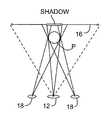
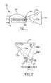
- FIG. 1is a schematic side view of a projection system including an apparatus for inhibiting a subject's eyes from being exposed to projected light;
- FIG. 2is a top plan view of the projection system of FIG. 1 ;
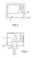
- FIG. 3is a front view of a projection screen on which a projected image is displayed
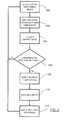
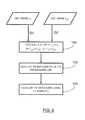
- FIG. 4is a flowchart showing the steps performed during processing of captured images to detect the presence of a presenter and to mask an output video data stream;
- FIG. 5is a front view showing a presenter positioned in front of the projection screen
- FIG. 6is a flowchart showing the steps performed during processing of captured images to generate a disparity image
- FIGS. 7 a and 7 bare flowcharts showing the steps performed during processing of captured images to detect the center of the presenter's head
- FIG. 8is a flowchart showing the steps performed during processing of captured images to track the center of the presenter's head
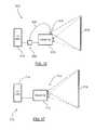
- FIG. 9is a top plan view of an alternative camera and projector arrangement for the projection system.
- FIG. 10is a front view of the camera and projector arrangement of FIG. 9 ;
- FIGS. 11 a and 11 bare front views of further alternative camera and projector arrangements
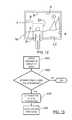
- FIG. 12is a front view showing a presenter positioned in front of the projection screen
- FIG. 13is a flowchart showing alterative steps performed during processing of captured images to detect the presence of a presenter and to mask an output video data stream;
- FIG. 14is a front view of the projection screen having a projected image displayed thereon, the displayed image including a subject detection band;
- FIG. 15is a front view of another embodiment of a projection screen on which a projected image is displayed
- FIG. 16is a schematic side view of a projection system including another embodiment of an apparatus for inhibiting a subject's eyes from being exposed to projected light;
- FIG. 17is a schematic side view of a projection system including yet another embodiment of an apparatus for inhibiting a subject's eyes from being exposed to projected light;
- FIGS. 18 a and 18 bare schematic side views of a projection system including yet another embodiment of an apparatus for inhibiting a subject's eyes from being exposed to projected light;
- FIG. 19is a schematic side view of a light beam generator and receiver and an associated scanning mechanism
- FIG. 20is a schematic side view of a projection system including still yet another embodiment of an apparatus for inhibiting a subject's eyes from being exposed to projected light;
- FIG. 21shows processing of projection screen sectors by the apparatus of FIG. 20 ;
- FIG. 22shows the masked video data stream projected on to the projection screen.
- projection system 10includes a projector 12 receiving an input video data stream from a processing device such as for example, a personal computer (PC) 14 .
- Projector 12in response to the input video data stream projects an image I onto a projection screen 16 as shown in FIG. 3 and by the dotted lines 12 a in FIGS. 1 and 2 .
- Projection screen 16may be for example a passive writeboard, an interactive writeboard such as those manufactured by SMART Technologies, Inc. of Calgary, Alberta, Canada or simply a background wall surface.
- a pair of low resolution video cameras 18is positioned adjacent the projector 12 .
- the cameras 18are horizontally spaced with one camera 18 being positioned in line with and above the projector 12 and the other camera 18 being positioned to the right side of the projector 12 .
- Each camera 18has a field of view (FOV) encompassing the projection screen 16 as shown in FIG. 3 and by the dotted lines 18 a in FIGS. 1 and 2 .
- FOVfield of view
- the cameras 18capture images including the entire projection screen 16 and the image I displayed thereon as well as any objects, such as a presenter P, positioned in front of the projection screen 16 .
- the cameras 18are coupled to the personal computer 14 via universal serial bus (USB) connections 20 .
- USBuniversal serial bus
- the projection system 10makes use of image analysis to mask the input video data stream provided to the projector 12 so that pixels corresponding to a region generally encompassing the presenter's head are set to black or near black (i.e. dimmed). In this manner, the presenter P is able to stand in front of the projection screen 16 and look back at the projector 12 without being blinded by projected light.
- the projection system 10Prior to general use of the projection system 10 , the projection system 10 is calibrated. Calibration of the projection system 10 matches the views of the cameras 18 through an image transformation with respect to the surface of the projection screen 16 such that image superposition creates one image of the viewed scene. Foreground objects such as a presenter are separated from the plane of the projection screen 16 due to the effect of planar parallax and show up as two images of finite separation related to the stereo camera positions. The calibration is fully automated without requiring intervention from the presenter or requiring projecting of special images that are visible during calibration.
- a Windows® desktop or other conventional graphical interface having icons and rectangular or arbitrarily shaped objects as image “features”is displayed on the projection screen 16 .
- the cameras 18in turn capture images including the projection screen 16 and the calibration desktop displayed thereon.
- the captured image pairis conveyed to the computer 14 which uses an image corner detector such as the Harris or SUSAN corner detector to locate unique points corresponding to corners in the captured images.
- a list of located points for each captured imageis in turn generated. Typically, many of the same points are found in each of the captured images as well as some non-matching “rogue” points.
- the two lists of pointsare then normalized for further numerical processing.
- each of the pointsis combined into a Gaussian weighted proximity matrix of inter-point distances with cross correlation strengths, in the neighborhood of the points in the lists, indicating the association strength of each point in the lists with every other point in the lists.
- Each of the values Pij of matrix Pif maximum on both the row and column, represents a 1:1 correspondence pairing of points in the lists and hence detected matching corners in the captured images.
- the matrix Phas the property of amplifying good pairings and attenuating bad pairings.
- the points in the lists that are found to be in 1:1 correspondenceare further processed to compute a homography transformation matrix with an over-determined linear set of equations to solve that enables the images captured by the cameras 18 to be mapped to one another.
- cornerstend to be relatively easy to find in computer generated displays due to the nature of icons and view windows within graphical user interfaces.
- the captured imageshave strong corner features at the four extreme corners of the projection screen 16 providing information about the relative size and position of the projection screen in the view of the cameras 18 .
- the personal computer 14outputs a video data stream that is received by the projector 12 .
- the projector 12In response to the input video data stream, the projector 12 in turn projects an image I onto the projection screen 16 .
- the cameras 18which see the projection screen 16 , the displayed image I and a presenter, if the presenter exists in their fields of view, capture images and convey the captured images to the personal computer 14 over the USB connections 20 .
- the computer 14receives pairs of images from the cameras 18 .
- the computer 14Upon receipt of each pair of images from the cameras 18 , the computer 14 processes the images to detect whether a presenter is positioned in front of the projection screen 16 and if so, to determine the location of the presenter's head so that the video data stream input to the projector 12 can be masked to inhibit the presenter from being blinded by projected light.
- the computer 14when the computer 14 receives the images from the cameras 18 (step 100 ), the computer 14 applies the homography transformation matrix calculated during calibration to the right camera image to transform the right camera image to the coordinate system of the left camera image (step 102 ). With the two images in the same coordinate system, a statistical cross-correlation between the images is performed to generate a “disparity” image (step 104 ).
- the disparity imageis then examined to determine if a presenter exists in the disparity image (step 106 ). If the existence of a presenter is not detected, the camera images are discarded and the process reverts back to step 100 to await receipt of the next pair of camera images.
- the disparity imageis further processed to detect the center of the presenter's head (step 108 ).
- the presenter's headis tracked (step 110 ) and the average center position and velocity of the presenter's head over successive image pairs is used to mask the video data stream so that pixels corresponding to a circular region encompassing the presenter's head are set to black or near black (step 112 ).
- the video data streamis output to the projector 12 , projected light is inhibited from being directed at the presenter's eyes as a circular area of darkness 24 encompasses the presenter's head as shown in FIG. 5 .
- the cameras 18continually capture images of the projection screen 16 and displayed image I, movement of the presenter P is tracked allowing the area of darkness 24 to be moved to follow the presenter.
- I LCis the image captured by the left camera
- I TRCis the transformed image captured by the right camera.
- a box filter of the appropriate kernel sizeis then applied to each image A, B and C (step 152 ).
- the equation used to generate the disparity imageis subject to a divide by zero (or close to zero) exception during tracking of dark objects in the captured images.
- Hardware and/or software interruptsare therefore employed to replace such divide by zero exceptions with numbers that are in a range that will yield a reasonable result.
- Overexposing the cameras 18 such that dark objects do not appear as absolute black and have some minimal level of illuminationcan also be performed to avoid the divide by zero exceptions.
- the disparity imagemay be found by filtering a difference image based on the captured left and transformed right captured images or by generating a Gaussian weighted difference image based on the captured left and transformed right captured images.
- the complexity of calculating a square root and performing a divide operationare avoided.
- the disparity imageis initially preprocessed.
- the disparity imageis firstly converted to greyscale so that the pixel values are in the range of 0 to 255 (step 200 ).
- the greyscale imageis then thresholded (step 202 ).
- pixels having values above 245 and below 220are set to black and pixels having values in the range of 220 to 245 representing a disparity (i.e. an object in front of the projection screen 16 ) are set to white.
- a region of interest (ROI) within the thresholded image that encompasses the majority of the white pixelsis then selected (step 204 ).
- ROIregion of interest
- a morphological open operationis then performed on the thresholded image to remove noise (step 208 ) and a flood fill operation is performed (step 208 ) to remove white pixel clusters that are smaller than a threshold size, in this example smaller than 2% of the projection screen area in the captured images. In this manner, the remaining white pixel clusters representing the presenter are isolated.
- the center (x,y) of the presenteris calculated based on the white pixel clusters in the region of interest (ROI).
- a principle component analysisis then performed on the white pixel clusters in the ROI (step 210 ) to detect the major axis of the presenter, the minor axis of the presenter and the orientation of the major axis with respect to the vertical.
- the principle component analysis resultsare used to calculate the centerline of the presenter's head and top of the presenter along the center line (step 214 in FIG. 7 b ).
- the top outline of the presenter's headis then calculated and possible head positions are determined (step 216 ).
- the right and left side outlines of the presenterare calculated and the actual head position is determined (step 218 ).
- the center of the presenter's headis calculated (step 220 ).
- one or two mathematical profiles referred to as rotational profilesmay be fitted to the outline to locate the presenter's head.
- step 110during tracking, after the center position of the presenter's head has been calculated at step 220 , the center position is stored in memory (step 300 in FIG. 8 ). A check is then made to determine if a threshold number of center positions are stored in the memory (step 302 ). If not, the process reverts back to step 300 awaiting the next calculated head center position. If a threshold number of center positions exist, a historical center position data group and a historical velocity data group are formed (steps 304 and 306 ).
- a median filteris then applied to the historical center position data group (step 308 ) and an average center position (X ay , Y ax ) is calculated (step 310 )
- a median filteris also applied to the historical velocity data group (step 312 ) and an average velocity (V ax , V ay ) is calculated (step 314 ).
- This center position (P x , P y )is used to calculate a circular mask encompassing the presenter's head (step 312 ).
- the pixels of the video data stream falling within the circular maskare then dimmed as described above so that when the video data stream is input to the projector 12 and a resultant image is projected on the projection screen 16 , the area of darkness 24 encompasses the presenter's head inhibiting the presenter from being blinded by projected light.
- the projection system 10tracks a presenter moving in front of the projection screen 16 and masks the video data stream input to the projector 12 to inhibit the presenter from being blinded.
- the camera imagesmay of course be processed in other ways to detect the presenter's head.
- the computer 14upon receipt of the images from the cameras 18 , the computer 14 initially equalizes the images to compensate for differences in exposure level prior to transforming the right camera image to the coordinate system of the left camera image.
- a weighted differential image based on the left camera image and transformed right camera imageis then calculated thereby to yield a disparity image.
- the disparity imageis then examined to determine if a presenter exists in the disparity image (i.e. if the disparity image includes a number of non-zero pixels above a threshold). If a presenter exists in the disparity image, the disparity image is thresholded.
- the threshold valueis based on the input images received from the cameras 18 and the weighted differential image. Morphological operations are performed on the thresholded image and features corresponding to the presenter's head are extracted. A differential image using the current image and the previously generated image is then calculated and examined to detect presenter motion in successive image pairs. If presenter motion is detected, the thresholding is dynamically adjusted to improve the head feature extraction. The extracted head feature and detected presenter motion, if any, are used to calculate and track the head center position. This head center position data is then used to apply the mask to the video data stream as discussed above.
- the cameras 18may be calibrated to set camera exposure parameters to reduce differences in exposure levels of the left and right camera images. Where the cameras 18 cannot be calibrated to set the exposure parameters, a greyscale level transfer function is generated and an absolute differential image is calculated. Depending on the sum of pixel values, a decision is made as to whether a presenter exists in the differential image. If a presenter exists in the image, a threshold is applied to the differential image to yield a binary disparity image. Morphological operations and feature filtering are performed on the thresholded image and features corresponding to the presenter's head are extracted. A time differential image using the current image and the corresponding image from the previous frame is generated and threshold to detect presenter motion in successive image pairs.
- the thresholdingis dynamically adjusted to improve the head feature extraction.
- the extracted head feature and detected presenter motion, if any,are used to calculate and track the head center position. This head center position data is then used to apply the mask to the video data stream as discussed above.
- the calibration method described aboveuses a corner detector to determine points in the captured images representing corners
- the calibration methodcan be extended from points to lines using properly parameterized equations of straight edges to locate straight lines in the captured images.
- lens distortioncan increase the complexity of line finding methods due to inherent curvature of otherwise straight lines.
- color informationmay be used to further improve the results of the correlation-weighted proximity matrix by performing the correlation on RGB triplets.
- the calibration methodmakes use of a typical desktop image
- other calibration imagescan be used such as a pre-configured overlay image having desirable features to locate.
- the calibration imagemay be an alphanumeric company logo and/or registered trademarks that have aesthetic appeal yet offer repeatable calibration results.
- the company logocan be designed as a plug-in image module that is customizable by the presenter.
- FIGS. 9 and 10an alternative camera and projector arrangement for the projection system 10 is shown.
- the cameras 18are horizontally spaced, with each camera being positioned on either side and above the projector 12 .
- the cameras 18 and projector 12form an inverted isosceles triangle.
- the optical axes of the cameras 18are horizontal and parallel to one another.
- the camera imagesare processed by the computer 14 to detect the presenter's shadow on the projection screen 16 , which in turn is used to locate the presenter.
- the right camera imageis initially transformed.
- the camera imagesare then processed to detect the outline of the presenter's shadow.
- the shadowwill appear as a dark region compared to other areas of the camera images.
- the presenter's shadowis then analyzed to detect the presenter's head and the circular mask encompassing the presenter's head is calculated. The calculated circular mask is then applied to the video data stream output to the projector 12 .
- the circular maskis selected to be greater than the outline of the presenter's head. Selected pixels within the circular mask are not set to black so that a small amount of light within the area of darkness 24 exists. Thus, a real shadow is still created allowing the computer 14 to distinguish between real and artificial shadows.
- each arrangementcomprises three cameras 18 arranged to form an isosceles triangle.
- the lens of the projector 12is positioned at the center of the triangle.
- the orientation of the triangle defined by the cameras 18is arbitrary, for symmetry and aesthetics, it is preferred that the vertex of the triangle be positioned either below the projector 12 as shown in FIG. 11 a or above the projector as shown in FIG. 11 b.
- a single camera 18 in line with and above the projector 12is used to capture images of the projection screen 16 .
- each captured imageis analyzed by the computer 14 to detect the boundary B of the displayed image I on the projection screen 16 (see FIG. 12 and step 400 in FIG. 13 ). This is done by examining each captured image to detect a sharp bright to dark transition that is generally rectangular in shape and near the outer edges of the captured image.
- the boundary B of the displayed image Iknown, the existence of the presenter P is determined by examining the lower edge LE of the image boundary to detect an interruption in the lower edge LE (step 402 ).
- the midpoint of the presenteris calculated followed by a presenter centerline (step 404 ). A rectangular mask extending along the centerline is then calculated and applied to the video data stream.
- the existence of the presenter Pis determined by finding the boundary of the displayed image and then locating an interruption in the lower edge of the displayed image boundary
- alternativesare available.
- the video data stream output by the personal computer 14is modified so that a narrow, generally horizontal bright white band 500 appears in the displayed image I adjacent its lower boundary.
- the camera 18processes each captured image to locate the bright white band 500 and any interruption therein signifying the existence of the presenter P.
- a strip of highly reflective or retro-reflective material 502can be provided adjacent the lower edge of the projection screen 16 as shown in FIG. 15 .
- the reflective or retro-reflective strip 502is positioned so that it is encompassed by the displayed image I and thus, reflects projected light. As a result, a generally horizontal bright white band appears in captured images.
- the camera 18processes each captured image to locate the bright white band and any interruption therein signifying the existence of the presenter P.
- the camera 18should be positioned very close to the lens of the projector 12 .
- the captured imagesmay be processed by the camera to detect the existence of the presenter P if the camera has on-board processing capabilities.
- the projection system 610includes a projector 612 that projects an image to be displayed onto a projection screen 616 .
- a single, low resolution camera 618is positioned adjacent the projector 612 and has a field of view encompassing the projection screen 616 . In this manner, the camera 618 captures images including the entire projection screen 616 and the image displayed thereon.
- the camera 618is coupled to a pixel interceptor 650 via a universal serial bus (USB) or other suitable connection 620 .
- Pixel interceptor 650receives a video data stream output by a video source 614 such as for example a personal computer, DVD player etc. and outputs a modified video data stream to the projector 612 .
- the video data stream provided to the projector 612is masked to ensure that light projected by the projector is inhibited from being directed at the presenter's eyes.
- the camera 618processes each captured image to detect the existence of the presenter and the presenter centerline.
- the presenter centerline informationis conveyed to the pixel interceptor 650 .
- the pixel interceptor 650uses the presenter centerline information to mask the received video data stream in the same manner described previously with reference to FIGS. 12 and 13 .
- the pixel interceptor 650uses the presenter centerline information to set pixel data corresponding to a rectangular region generally encompassing the presenter to black or near black thereby to ensure that the resulting area of darkness 24 in the projected image inhibits light from being directed at the presenter's eyes.
- the camerais shown as being positioned adjacent the projector. Positioning the camera adjacent the projector is typically convenient as connections to a power source and the video data source are readily available. If a strip of retro-reflective material 502 is not used in the detection of a presenter's existence, those of skill in the art will appreciate that the camera need not be positioned adjacent the projector.
- the cameracan be positioned basically at any location provided its field of view encompasses the displayed image and projection screen.
- the projection system 710includes a projector 712 that projects an image to be displayed onto a projection screen 716 .
- a single, low resolution camera 718is built into the projector and has a field of view encompassing the projection screen 716 .
- the camera 718captures images including the entire projection screen 716 and the image displayed thereon.
- the projector 712 in this examplealso includes a built-in pixel interceptor.
- the projector 712receives a video data stream output by a video source 714 such as for example a personal computer, DVD player etc. Prior to using the input video data stream to project an image, the projector 712 modifies the video data stream to ensure that light projected by the projector 712 is inhibited from being directed at the presenter's eyes.
- FIGS. 18 a and 18 byet another embodiment of a projection system 810 is shown.
- a range finder 818is disposed on the projector 812 .
- the range finder 818projects a beam 821 of sound, light or radio waves towards the projection screen 816 that is used to scan the projection screen.
- the projected beam 821is reflected back towards the range finder 818 and is received by the range finder sooner than if the beam 821 had reached the projection screen 816 allowing the existence and position of the presenter to be determined.
- the range finder outputis conveyed to the computer 14 and is processed to locate the position of the presenter.
- the presenter locationis used to mask the video data stream output to the projector 812 to inhibit the presenter from being blinded by projected light.
- the projected beam 821can be swept outside of the area of the projection screen 816 to allow pre-emptive shading by detecting the existence of the presenter before the presenter moves in front of the projection screen.
- the computer 14compares the range finder output along each horizontal image scan line with calibration values.
- the calibration valuesrepresent the elapsed time taken for the beam 821 to reflect back from the projection screen 816 in the absence of a presenter. In this manner, the existence and location of the presenter can be determined.
- the range finder 818can be used in conjunction with one or more cameras.
- the range finder informationis used by the computer 14 to quickly identify the location of the presenter. Using this location information, the appropriate areas of the captured camera images are processed so that the video data stream output to the projector 812 can be masked to inhibit the presenter from being blinded by projected light.
- a light beam generator and receiver 850 in combination with a scanning mechanism 852can be used to scan the projection screen 816 to detect the existence and location of a presenter.
- the scanning mechanism 852comprises a mirror 854 that is pivoted about a spherical joint 856 by an actuator (not shown) to scan a light beam generated by the light beam generator and receiver 850 horizontally across the projection screen. Reflected light returning to the mirror 854 is reflected back onto the light beam generator and receiver 850 . Assuming that light reflected off of the presenter has a lower optical power than light reflecting off of the projection screen 816 , the existence and location of the presenter can be determined.
- a light sensing device 918 positioned above the projector 912is used to detect the existence of a presenter positioned in front of the projection screen 916 .
- the light sensing device 918detects light that is reflected back towards it.
- Light reflected from the projection screen 916reflects relatively uniformly while light reflected from a presenter does not.
- Light picked up by the light sensing device 918is compared with known values determined during calibration in the absence of a presenter. When a presenter is positioned in front of the projection screen 916 , the reflected light has a different luminosity and arrives at the light sensing device 918 sooner than it would if the light had traveled to the projection screen 916 .
- the projection screenis divided into sectors.
- the computer 14compares the output of the light sensing device 918 for each sector with calibration values to determine if a presenter is detected as shown in FIG. 21 . Once the light sensing device output for all sectors has been processed, the video data stream input to the projector 912 is masked to set the pixels of each sector in which the presenter has been detected to black as shown in FIG. 22 .
- the existence of a presenter in front of the projection screenis detected so that the video data stream used by a projector to project an image onto the projection screen can be masked to inhibit projected light from being directed at the presenter's eyes.
- the region of pixels that is maskedcan be of basically any shape and size so long as the region encompasses the presenter's eyes. Thus, the region can be sized and shaped to encompass only the presenter's eyes. Also, during modification, the pixels in the region need not be set to black or near black. The values of the pixels can be set to other levels provided the values avoid the presenter from being blinded by the projected light.
Landscapes
- Engineering & Computer Science (AREA)
- Multimedia (AREA)
- Signal Processing (AREA)
- Physics & Mathematics (AREA)
- General Physics & Mathematics (AREA)
- Projection Apparatus (AREA)
- Controls And Circuits For Display Device (AREA)
Abstract
Description
G=TDU′
P=TEU′
A=ILC×ILC
B=ITRC×ITRC
C=ILC×ITRC
where:
P=A/sqrt(B×C)
Px=Xay+VaxΔt
Py=Yax+VayΔt
Claims (44)
Priority Applications (4)
| Application Number | Priority Date | Filing Date | Title |
|---|---|---|---|
| US11/420,146US7984995B2 (en) | 2006-05-24 | 2006-05-24 | Method and apparatus for inhibiting a subject's eyes from being exposed to projected light |
| PCT/CA2007/000908WO2007134456A1 (en) | 2006-05-24 | 2007-05-24 | Method and apparatus for inhibiting a subject's eyes from being exposed to projected light |
| US11/773,319US7686460B2 (en) | 2006-05-24 | 2007-07-03 | Method and apparatus for inhibiting a subject's eyes from being exposed to projected light |
| US12/732,709US20100182416A1 (en) | 2006-05-24 | 2010-03-26 | Method and apparatus for inhibiting a subject's eyes from being exposed to projected light |
Applications Claiming Priority (1)
| Application Number | Priority Date | Filing Date | Title |
|---|---|---|---|
| US11/420,146US7984995B2 (en) | 2006-05-24 | 2006-05-24 | Method and apparatus for inhibiting a subject's eyes from being exposed to projected light |
Related Child Applications (1)
| Application Number | Title | Priority Date | Filing Date |
|---|---|---|---|
| US11/773,319Continuation-In-PartUS7686460B2 (en) | 2006-05-24 | 2007-07-03 | Method and apparatus for inhibiting a subject's eyes from being exposed to projected light |
Publications (2)
| Publication Number | Publication Date |
|---|---|
| US20070273842A1 US20070273842A1 (en) | 2007-11-29 |
| US7984995B2true US7984995B2 (en) | 2011-07-26 |
Family
ID=38722913
Family Applications (3)
| Application Number | Title | Priority Date | Filing Date |
|---|---|---|---|
| US11/420,146Active2028-08-26US7984995B2 (en) | 2006-05-24 | 2006-05-24 | Method and apparatus for inhibiting a subject's eyes from being exposed to projected light |
| US11/773,319Active2026-06-10US7686460B2 (en) | 2006-05-24 | 2007-07-03 | Method and apparatus for inhibiting a subject's eyes from being exposed to projected light |
| US12/732,709AbandonedUS20100182416A1 (en) | 2006-05-24 | 2010-03-26 | Method and apparatus for inhibiting a subject's eyes from being exposed to projected light |
Family Applications After (2)
| Application Number | Title | Priority Date | Filing Date |
|---|---|---|---|
| US11/773,319Active2026-06-10US7686460B2 (en) | 2006-05-24 | 2007-07-03 | Method and apparatus for inhibiting a subject's eyes from being exposed to projected light |
| US12/732,709AbandonedUS20100182416A1 (en) | 2006-05-24 | 2010-03-26 | Method and apparatus for inhibiting a subject's eyes from being exposed to projected light |
Country Status (2)
| Country | Link |
|---|---|
| US (3) | US7984995B2 (en) |
| WO (1) | WO2007134456A1 (en) |
Cited By (6)
| Publication number | Priority date | Publication date | Assignee | Title |
|---|---|---|---|---|
| US20120092630A1 (en)* | 2009-07-31 | 2012-04-19 | Kunitaka Furuichi | Projection type display device and light amount adjustment method |
| US20130120763A1 (en)* | 2010-07-16 | 2013-05-16 | Eric Grenet | Measurement system of a light source in space |
| US20150378250A1 (en)* | 2014-06-26 | 2015-12-31 | Panasonic Intellectual Property Management Co., Ltd. | Light projection apparatus and illumination apparatus using same |
| US10027934B1 (en) | 2017-01-03 | 2018-07-17 | International Business Machines Corporation | Prohibiting facial exposure to projected light |
| US10685478B1 (en)* | 2018-06-14 | 2020-06-16 | Kilburn Live, Llc | Mitigating projector glare by real-time dynamic shadow masking |
| CN111856866A (en)* | 2019-04-30 | 2020-10-30 | 中强光电股份有限公司 | Projection device and operation method thereof |
Families Citing this family (87)
| Publication number | Priority date | Publication date | Assignee | Title |
|---|---|---|---|---|
| US6803906B1 (en) | 2000-07-05 | 2004-10-12 | Smart Technologies, Inc. | Passive touch system and method of detecting user input |
| US6954197B2 (en) | 2002-11-15 | 2005-10-11 | Smart Technologies Inc. | Size/scale and orientation determination of a pointer in a camera-based touch system |
| US7629967B2 (en) | 2003-02-14 | 2009-12-08 | Next Holdings Limited | Touch screen signal processing |
| US8456447B2 (en) | 2003-02-14 | 2013-06-04 | Next Holdings Limited | Touch screen signal processing |
| US8508508B2 (en) | 2003-02-14 | 2013-08-13 | Next Holdings Limited | Touch screen signal processing with single-point calibration |
| US7532206B2 (en) | 2003-03-11 | 2009-05-12 | Smart Technologies Ulc | System and method for differentiating between pointers used to contact touch surface |
| US7411575B2 (en) | 2003-09-16 | 2008-08-12 | Smart Technologies Ulc | Gesture recognition method and touch system incorporating the same |
| US7274356B2 (en) | 2003-10-09 | 2007-09-25 | Smart Technologies Inc. | Apparatus for determining the location of a pointer within a region of interest |
| US7355593B2 (en) | 2004-01-02 | 2008-04-08 | Smart Technologies, Inc. | Pointer tracking across multiple overlapping coordinate input sub-regions defining a generally contiguous input region |
| US7460110B2 (en) | 2004-04-29 | 2008-12-02 | Smart Technologies Ulc | Dual mode touch system |
| US7538759B2 (en) | 2004-05-07 | 2009-05-26 | Next Holdings Limited | Touch panel display system with illumination and detection provided from a single edge |
| US8120596B2 (en) | 2004-05-21 | 2012-02-21 | Smart Technologies Ulc | Tiled touch system |
| JP5023587B2 (en)* | 2006-07-18 | 2012-09-12 | 富士ゼロックス株式会社 | Image display device and image display method |
| US9442607B2 (en) | 2006-12-04 | 2016-09-13 | Smart Technologies Inc. | Interactive input system and method |
| US8115753B2 (en) | 2007-04-11 | 2012-02-14 | Next Holdings Limited | Touch screen system with hover and click input methods |
| JP5088018B2 (en)* | 2007-06-28 | 2012-12-05 | 富士ゼロックス株式会社 | Image processing apparatus and control program |
| US8094137B2 (en) | 2007-07-23 | 2012-01-10 | Smart Technologies Ulc | System and method of detecting contact on a display |
| US8384693B2 (en) | 2007-08-30 | 2013-02-26 | Next Holdings Limited | Low profile touch panel systems |
| WO2009029767A1 (en) | 2007-08-30 | 2009-03-05 | Next Holdings, Inc. | Optical touchscreen with improved illumination |
| GB2454685A (en)* | 2007-11-14 | 2009-05-20 | Everest Display Inc | Projector having silhouette or black mask that tracks the user to prevent eye damage. |
| US20090147272A1 (en)* | 2007-12-05 | 2009-06-11 | Microvision, Inc. | Proximity detection for control of an imaging device |
| US8007110B2 (en)* | 2007-12-28 | 2011-08-30 | Motorola Mobility, Inc. | Projector system employing depth perception to detect speaker position and gestures |
| US8405636B2 (en) | 2008-01-07 | 2013-03-26 | Next Holdings Limited | Optical position sensing system and optical position sensor assembly |
| US9241143B2 (en)* | 2008-01-29 | 2016-01-19 | At&T Intellectual Property I, L.P. | Output correction for visual projection devices |
| JP4871315B2 (en)* | 2008-03-26 | 2012-02-08 | 富士フイルム株式会社 | Compound eye photographing apparatus, control method therefor, and program |
| US20090278795A1 (en)* | 2008-05-09 | 2009-11-12 | Smart Technologies Ulc | Interactive Input System And Illumination Assembly Therefor |
| US8902193B2 (en) | 2008-05-09 | 2014-12-02 | Smart Technologies Ulc | Interactive input system and bezel therefor |
| US8308304B2 (en) | 2008-06-17 | 2012-11-13 | The Invention Science Fund I, Llc | Systems associated with receiving and transmitting information related to projection |
| US8384005B2 (en) | 2008-06-17 | 2013-02-26 | The Invention Science Fund I, Llc | Systems and methods for selectively projecting information in response to at least one specified motion associated with pressure applied to at least one projection surface |
| US8820939B2 (en) | 2008-06-17 | 2014-09-02 | The Invention Science Fund I, Llc | Projection associated methods and systems |
| US8608321B2 (en) | 2008-06-17 | 2013-12-17 | The Invention Science Fund I, Llc | Systems and methods for projecting in response to conformation |
| US8267526B2 (en) | 2008-06-17 | 2012-09-18 | The Invention Science Fund I, Llc | Methods associated with receiving and transmitting information related to projection |
| US8944608B2 (en)* | 2008-06-17 | 2015-02-03 | The Invention Science Fund I, Llc | Systems and methods associated with projecting in response to conformation |
| US8723787B2 (en) | 2008-06-17 | 2014-05-13 | The Invention Science Fund I, Llc | Methods and systems related to an image capture projection surface |
| US20090309826A1 (en) | 2008-06-17 | 2009-12-17 | Searete Llc, A Limited Liability Corporation Of The State Of Delaware | Systems and devices |
| US8936367B2 (en) | 2008-06-17 | 2015-01-20 | The Invention Science Fund I, Llc | Systems and methods associated with projecting in response to conformation |
| US8430515B2 (en) | 2008-06-17 | 2013-04-30 | The Invention Science Fund I, Llc | Systems and methods for projecting |
| US8641203B2 (en) | 2008-06-17 | 2014-02-04 | The Invention Science Fund I, Llc | Methods and systems for receiving and transmitting signals between server and projector apparatuses |
| US8733952B2 (en) | 2008-06-17 | 2014-05-27 | The Invention Science Fund I, Llc | Methods and systems for coordinated use of two or more user responsive projectors |
| US8262236B2 (en) | 2008-06-17 | 2012-09-11 | The Invention Science Fund I, Llc | Systems and methods for transmitting information associated with change of a projection surface |
| US8602564B2 (en) | 2008-06-17 | 2013-12-10 | The Invention Science Fund I, Llc | Methods and systems for projecting in response to position |
| US20100079409A1 (en)* | 2008-09-29 | 2010-04-01 | Smart Technologies Ulc | Touch panel for an interactive input system, and interactive input system incorporating the touch panel |
| US8810522B2 (en)* | 2008-09-29 | 2014-08-19 | Smart Technologies Ulc | Method for selecting and manipulating a graphical object in an interactive input system, and interactive input system executing the method |
| US20100079385A1 (en)* | 2008-09-29 | 2010-04-01 | Smart Technologies Ulc | Method for calibrating an interactive input system and interactive input system executing the calibration method |
| US20100083109A1 (en)* | 2008-09-29 | 2010-04-01 | Smart Technologies Ulc | Method for handling interactions with multiple users of an interactive input system, and interactive input system executing the method |
| US8427424B2 (en) | 2008-09-30 | 2013-04-23 | Microsoft Corporation | Using physical objects in conjunction with an interactive surface |
| US8339378B2 (en) | 2008-11-05 | 2012-12-25 | Smart Technologies Ulc | Interactive input system with multi-angle reflector |
| US20120019441A1 (en)* | 2009-03-26 | 2012-01-26 | Kyocera Corporation | Mobile electronic device |
| DE102010023108B4 (en)* | 2009-06-04 | 2019-12-05 | Sypro Optics Gmbh | Projector with automatic focusing and imaging process |
| US8416206B2 (en)* | 2009-07-08 | 2013-04-09 | Smart Technologies Ulc | Method for manipulating a graphic widget in a three-dimensional environment displayed on a touch panel of an interactive input system |
| EP2473904A1 (en)* | 2009-09-01 | 2012-07-11 | SMART Technologies ULC | Interactive input system with improved signal-to-noise ratio (snr) and image capture method |
| US20110095989A1 (en)* | 2009-10-23 | 2011-04-28 | Smart Technologies Ulc | Interactive input system and bezel therefor |
| USD633097S1 (en)* | 2009-12-14 | 2011-02-22 | Xerox Corporation | Display screen with a copier assistant application icon |
| US8502789B2 (en) | 2010-01-11 | 2013-08-06 | Smart Technologies Ulc | Method for handling user input in an interactive input system, and interactive input system executing the method |
| US8730309B2 (en) | 2010-02-23 | 2014-05-20 | Microsoft Corporation | Projectors and depth cameras for deviceless augmented reality and interaction |
| JP5170176B2 (en)* | 2010-06-30 | 2013-03-27 | ソニー株式会社 | Object judgment system, object judgment method and program |
| JP5238767B2 (en)* | 2010-07-26 | 2013-07-17 | 株式会社東芝 | Parallax image generation method and apparatus |
| KR101714050B1 (en)* | 2010-11-01 | 2017-03-08 | 삼성전자주식회사 | Device and method for displaying data in wireless terminal |
| US9329469B2 (en) | 2011-02-17 | 2016-05-03 | Microsoft Technology Licensing, Llc | Providing an interactive experience using a 3D depth camera and a 3D projector |
| US9480907B2 (en) | 2011-03-02 | 2016-11-01 | Microsoft Technology Licensing, Llc | Immersive display with peripheral illusions |
| US20120223885A1 (en)* | 2011-03-02 | 2012-09-06 | Microsoft Corporation | Immersive display experience |
| JP5643153B2 (en)* | 2011-05-23 | 2014-12-17 | パナソニック株式会社 | Optical projection device |
| US9597587B2 (en) | 2011-06-08 | 2017-03-21 | Microsoft Technology Licensing, Llc | Locational node device |
| WO2012171110A1 (en) | 2011-06-15 | 2012-12-20 | Smart Technologies Ulc | Interactive surface with user proximity detection |
| JP2013033206A (en)* | 2011-07-06 | 2013-02-14 | Ricoh Co Ltd | Projection display device, information processing device, projection display system, and program |
| US8979273B2 (en)* | 2011-11-16 | 2015-03-17 | Seiko Epson Corporation | Line display system using projector |
| TW201329508A (en)* | 2012-01-04 | 2013-07-16 | Walsin Lihwa Corp | Device and method for protecting eyes |
| JP2013156324A (en)* | 2012-01-27 | 2013-08-15 | Seiko Epson Corp | Projector and image projection method by the same |
| USD677270S1 (en)* | 2012-02-28 | 2013-03-05 | Microsoft Corporation | Display screen with icon set |
| JP2013195865A (en)* | 2012-03-22 | 2013-09-30 | Ricoh Co Ltd | Projector, projector control method and projector control program |
| JPWO2013186994A1 (en)* | 2012-06-15 | 2016-02-04 | 日本電気株式会社 | Projection type projection device, light anti-glare method, and light anti-glare program |
| US9197870B1 (en) | 2012-09-12 | 2015-11-24 | Amazon Technologies, Inc. | Automatic projection focusing |
| US10285141B1 (en)* | 2012-09-19 | 2019-05-07 | Safeco Insurance Company Of America | Data synchronization across multiple sensors |
| KR101526294B1 (en)* | 2013-08-26 | 2015-06-05 | 씨제이씨지브이 주식회사 | Apparatus and method for generating guide image using parameter |
| JP2015060211A (en)* | 2013-09-20 | 2015-03-30 | カシオ計算機株式会社 | Projection device, program, and projection control method |
| JP6459194B2 (en)* | 2014-03-20 | 2019-01-30 | セイコーエプソン株式会社 | Projector and projected image control method |
| US9304599B2 (en) | 2014-03-21 | 2016-04-05 | Dell Products L.P. | Gesture controlled adaptive projected information handling system input and output devices |
| US20150268773A1 (en)* | 2014-03-21 | 2015-09-24 | Dell Products L.P. | Projected Information Handling System Input Interface with Dynamic Adjustment |
| US10133355B2 (en) | 2014-03-21 | 2018-11-20 | Dell Products L.P. | Interactive projected information handling system support input and output devices |
| US9965038B2 (en) | 2014-03-21 | 2018-05-08 | Dell Products L.P. | Context adaptable projected information handling system input environment |
| JP2017531976A (en)* | 2014-09-29 | 2017-10-26 | フォトネイション ケイマン リミテッド | System and method for dynamically calibrating an array camera |
| CZ2015879A3 (en)* | 2015-12-09 | 2017-04-12 | LTR s.r.o. | A method of using the system for acceleration of visual feedback with a camera manipulator and the system for acceleration of visual feedback with a camera manipulator |
| JP6642032B2 (en)* | 2016-01-21 | 2020-02-05 | セイコーエプソン株式会社 | Projector and projector control method |
| US10885676B2 (en)* | 2016-12-27 | 2021-01-05 | Samsung Electronics Co., Ltd. | Method and apparatus for modifying display settings in virtual/augmented reality |
| WO2018167999A1 (en)* | 2017-03-17 | 2018-09-20 | パナソニックIpマネジメント株式会社 | Projector and projector system |
| US10853911B2 (en)* | 2018-04-17 | 2020-12-01 | Google Llc | Dynamic adaptation of images for projection, and/or of projection parameters, based on user(s) in environment |
| US20250024005A1 (en)* | 2023-07-14 | 2025-01-16 | Vladimir V. Maslinkovskiy | Real time masking of projected visual media |
Citations (34)
| Publication number | Priority date | Publication date | Assignee | Title |
|---|---|---|---|---|
| US5383013A (en) | 1992-09-18 | 1995-01-17 | Nec Research Institute, Inc. | Stereoscopic computer vision system |
| US5704836A (en)* | 1995-03-23 | 1998-01-06 | Perception Systems, Inc. | Motion-based command generation technology |
| US5844565A (en)* | 1994-04-15 | 1998-12-01 | Sony Corporation | Generating imitation custom artwork by simulating brush strokes and enhancing edges |
| US6361173B1 (en)* | 2001-02-16 | 2002-03-26 | Imatte, Inc. | Method and apparatus for inhibiting projection of selected areas of a projected image |
| US20020093666A1 (en) | 2001-01-17 | 2002-07-18 | Jonathan Foote | System and method for determining the location of a target in a room or small area |
| US20020097218A1 (en) | 2001-01-22 | 2002-07-25 | Philips Electronics North America Corporatin | Single camera system for gesture-based input and target indication |
| US20020105482A1 (en)* | 2000-05-26 | 2002-08-08 | Lemelson Jerome H. | System and methods for controlling automatic scrolling of information on a display or screen |
| US6483485B1 (en) | 1999-08-18 | 2002-11-19 | Jung-Tang Huang | Method and device for protecting eyes through screen displaying setting |
| US6529992B1 (en) | 1999-07-26 | 2003-03-04 | Iomega Corporation | Self-contained application disk for automatically launching application software or starting devices and peripherals |
| US20030046447A1 (en) | 2001-07-31 | 2003-03-06 | Konstantin Kouperchliak | Device-related software installation |
| US6542087B2 (en) | 2001-01-31 | 2003-04-01 | Hewlett-Packard Company | System and method for extracting a point of interest of an object in front of a computer controllable display captured by an imaging device |
| US20030182456A1 (en) | 2002-03-01 | 2003-09-25 | Acer Laboratories Inc. | Portable peripheral apparatus with an embedded storage module |
| US20030204950A1 (en) | 2002-05-01 | 2003-11-06 | Wen-Hwa Chou | Method of installing a plug and play device driver |
| US20030225971A1 (en) | 2002-05-29 | 2003-12-04 | Yuji Oishi | USB storage device and program |
| US20040015965A1 (en) | 2001-06-02 | 2004-01-22 | Malcom Sparks | Installation-free middleware demonstration system |
| US6704824B1 (en) | 1999-07-27 | 2004-03-09 | Inline Connection Corporation | Universal serial bus adapter with automatic installation |
| WO2004040428A1 (en) | 2002-11-01 | 2004-05-13 | Shinya Kobayashi | Detachable device, control circuit, control circuit firmware program, information processing method and circuit design pattern in control circuit, and log-in method |
| US6754725B1 (en) | 2001-05-07 | 2004-06-22 | Cypress Semiconductor Corp. | USB peripheral containing its own device driver |
| US20040165154A1 (en)* | 2003-02-21 | 2004-08-26 | Hitachi, Ltd. | Projector type display apparatus |
| US6789903B2 (en) | 2003-02-18 | 2004-09-14 | Imatte, Inc. | Generating an inhibit signal by pattern displacement |
| US20040205778A1 (en) | 2003-04-08 | 2004-10-14 | Wong Yin Hui | System and method for installing portable device drivers |
| US6811267B1 (en) | 2003-06-09 | 2004-11-02 | Hewlett-Packard Development Company, L.P. | Display system with nonvisible data projection |
| US20040230710A1 (en) | 1999-07-27 | 2004-11-18 | Inline Connection Corporation | System and method of automatic installation of computer peripherals |
| US20050038934A1 (en) | 2003-08-11 | 2005-02-17 | Infineon Technologies Ag | USB-based peripheral device and method for starting up the USB-based peripheral device |
| US6860604B1 (en)* | 2004-01-09 | 2005-03-01 | Imatte, Inc. | Method and apparatus for inhibiting the projection of a shadow of a presenter onto a projection screen |
| US20050097573A1 (en) | 1998-09-23 | 2005-05-05 | Microsoft Corporation | Device driver auto-load |
| US6898653B2 (en) | 2002-12-27 | 2005-05-24 | Neodio Technologies Corporation | Plug-and-play interconnection architecture and method with in-device storage module in peripheral device |
| US20050117132A1 (en)* | 2003-12-01 | 2005-06-02 | Eastman Kodak Company | Laser projector having silhouette blanking for objects in the output light path |
| US6906704B2 (en)* | 2002-01-24 | 2005-06-14 | Mega Chips Corporation | Noise elimination method and noise elimination apparatus |
| US6986030B2 (en) | 2000-10-27 | 2006-01-10 | M-Systems Flash Disk Pioneers Ltd. | Portable memory device includes software program for interacting with host computing device to provide a customized configuration for the program |
| US20060015676A1 (en) | 2004-07-15 | 2006-01-19 | Hiromichi Oribe | Semiconductor storage device |
| US7221437B1 (en) | 2002-08-20 | 2007-05-22 | Schaefer Philip R | Method and apparatus for measuring distances using light |
| US7230685B2 (en) | 2004-01-28 | 2007-06-12 | Denso Corporation | Apparatus, method, and program for generating range-image-data |
| US7325933B2 (en)* | 2004-08-09 | 2008-02-05 | Sanyo Electric Co., Ltd | Projection type video display apparatus |
Family Cites Families (1)
| Publication number | Priority date | Publication date | Assignee | Title |
|---|---|---|---|---|
| JP2004061446A (en)* | 2002-07-31 | 2004-02-26 | Fujitsu Ten Ltd | Pattern matching processing method and image processor |
- 2006
- 2006-05-24USUS11/420,146patent/US7984995B2/enactiveActive
- 2007
- 2007-05-24WOPCT/CA2007/000908patent/WO2007134456A1/enactiveApplication Filing
- 2007-07-03USUS11/773,319patent/US7686460B2/enactiveActive
- 2010
- 2010-03-26USUS12/732,709patent/US20100182416A1/ennot_activeAbandoned
Patent Citations (40)
| Publication number | Priority date | Publication date | Assignee | Title |
|---|---|---|---|---|
| US5383013A (en) | 1992-09-18 | 1995-01-17 | Nec Research Institute, Inc. | Stereoscopic computer vision system |
| US5844565A (en)* | 1994-04-15 | 1998-12-01 | Sony Corporation | Generating imitation custom artwork by simulating brush strokes and enhancing edges |
| US5704836A (en)* | 1995-03-23 | 1998-01-06 | Perception Systems, Inc. | Motion-based command generation technology |
| US20050097573A1 (en) | 1998-09-23 | 2005-05-05 | Microsoft Corporation | Device driver auto-load |
| US6529992B1 (en) | 1999-07-26 | 2003-03-04 | Iomega Corporation | Self-contained application disk for automatically launching application software or starting devices and peripherals |
| US6704824B1 (en) | 1999-07-27 | 2004-03-09 | Inline Connection Corporation | Universal serial bus adapter with automatic installation |
| US20040230710A1 (en) | 1999-07-27 | 2004-11-18 | Inline Connection Corporation | System and method of automatic installation of computer peripherals |
| US20040199909A1 (en) | 1999-07-27 | 2004-10-07 | Inline Connection Corporation | Universal serial bus adapter with automatic installation |
| US6483485B1 (en) | 1999-08-18 | 2002-11-19 | Jung-Tang Huang | Method and device for protecting eyes through screen displaying setting |
| US20020105482A1 (en)* | 2000-05-26 | 2002-08-08 | Lemelson Jerome H. | System and methods for controlling automatic scrolling of information on a display or screen |
| US6986030B2 (en) | 2000-10-27 | 2006-01-10 | M-Systems Flash Disk Pioneers Ltd. | Portable memory device includes software program for interacting with host computing device to provide a customized configuration for the program |
| US20020093666A1 (en) | 2001-01-17 | 2002-07-18 | Jonathan Foote | System and method for determining the location of a target in a room or small area |
| US6775014B2 (en)* | 2001-01-17 | 2004-08-10 | Fujixerox Co., Ltd. | System and method for determining the location of a target in a room or small area |
| US20020097218A1 (en) | 2001-01-22 | 2002-07-25 | Philips Electronics North America Corporatin | Single camera system for gesture-based input and target indication |
| US6542087B2 (en) | 2001-01-31 | 2003-04-01 | Hewlett-Packard Company | System and method for extracting a point of interest of an object in front of a computer controllable display captured by an imaging device |
| US20020113950A1 (en)* | 2001-02-16 | 2002-08-22 | Paul Vlahos | Interactive teleconferencing display system |
| US6361173B1 (en)* | 2001-02-16 | 2002-03-26 | Imatte, Inc. | Method and apparatus for inhibiting projection of selected areas of a projected image |
| US6754725B1 (en) | 2001-05-07 | 2004-06-22 | Cypress Semiconductor Corp. | USB peripheral containing its own device driver |
| US20040015965A1 (en) | 2001-06-02 | 2004-01-22 | Malcom Sparks | Installation-free middleware demonstration system |
| US20030046447A1 (en) | 2001-07-31 | 2003-03-06 | Konstantin Kouperchliak | Device-related software installation |
| US6906704B2 (en)* | 2002-01-24 | 2005-06-14 | Mega Chips Corporation | Noise elimination method and noise elimination apparatus |
| US20030182456A1 (en) | 2002-03-01 | 2003-09-25 | Acer Laboratories Inc. | Portable peripheral apparatus with an embedded storage module |
| US20030204950A1 (en) | 2002-05-01 | 2003-11-06 | Wen-Hwa Chou | Method of installing a plug and play device driver |
| US20030225971A1 (en) | 2002-05-29 | 2003-12-04 | Yuji Oishi | USB storage device and program |
| US7221437B1 (en) | 2002-08-20 | 2007-05-22 | Schaefer Philip R | Method and apparatus for measuring distances using light |
| EP1566726A1 (en) | 2002-11-01 | 2005-08-24 | Shinya Kobayashi | Detachable device, control circuit, control circuit firmware program, information processing method and circuit design pattern in control circuit, and log-in method |
| WO2004040428A1 (en) | 2002-11-01 | 2004-05-13 | Shinya Kobayashi | Detachable device, control circuit, control circuit firmware program, information processing method and circuit design pattern in control circuit, and log-in method |
| US6898653B2 (en) | 2002-12-27 | 2005-05-24 | Neodio Technologies Corporation | Plug-and-play interconnection architecture and method with in-device storage module in peripheral device |
| US6789903B2 (en) | 2003-02-18 | 2004-09-14 | Imatte, Inc. | Generating an inhibit signal by pattern displacement |
| US20040165154A1 (en)* | 2003-02-21 | 2004-08-26 | Hitachi, Ltd. | Projector type display apparatus |
| US7165844B2 (en) | 2003-02-21 | 2007-01-23 | Hitachi, Ltd. | Projector type display apparatus |
| US20040205778A1 (en) | 2003-04-08 | 2004-10-14 | Wong Yin Hui | System and method for installing portable device drivers |
| US6811267B1 (en) | 2003-06-09 | 2004-11-02 | Hewlett-Packard Development Company, L.P. | Display system with nonvisible data projection |
| US20050038934A1 (en) | 2003-08-11 | 2005-02-17 | Infineon Technologies Ag | USB-based peripheral device and method for starting up the USB-based peripheral device |
| US20050117132A1 (en)* | 2003-12-01 | 2005-06-02 | Eastman Kodak Company | Laser projector having silhouette blanking for objects in the output light path |
| US6984039B2 (en) | 2003-12-01 | 2006-01-10 | Eastman Kodak Company | Laser projector having silhouette blanking for objects in the output light path |
| US6860604B1 (en)* | 2004-01-09 | 2005-03-01 | Imatte, Inc. | Method and apparatus for inhibiting the projection of a shadow of a presenter onto a projection screen |
| US7230685B2 (en) | 2004-01-28 | 2007-06-12 | Denso Corporation | Apparatus, method, and program for generating range-image-data |
| US20060015676A1 (en) | 2004-07-15 | 2006-01-19 | Hiromichi Oribe | Semiconductor storage device |
| US7325933B2 (en)* | 2004-08-09 | 2008-02-05 | Sanyo Electric Co., Ltd | Projection type video display apparatus |
Non-Patent Citations (3)
| Title |
|---|
| ISR and Written Opinion for PCT/CA2007/000908 mailed Sep. 12, 2007 (10 pages). |
| James H. Stapleton; Linear Statistical Models; Wiley-Interscience; 1 edition (Jul. 14, 1995).* |
| Windows 95, Microsoft, Aug. 24, 1995.* |
Cited By (8)
| Publication number | Priority date | Publication date | Assignee | Title |
|---|---|---|---|---|
| US20120092630A1 (en)* | 2009-07-31 | 2012-04-19 | Kunitaka Furuichi | Projection type display device and light amount adjustment method |
| US20130120763A1 (en)* | 2010-07-16 | 2013-05-16 | Eric Grenet | Measurement system of a light source in space |
| US9103661B2 (en)* | 2010-07-16 | 2015-08-11 | CSEM Centre Suisse d'Electronique et de Microtechnique SA—Recherche et Developpment | Measurement system of a light source in space |
| US20150378250A1 (en)* | 2014-06-26 | 2015-12-31 | Panasonic Intellectual Property Management Co., Ltd. | Light projection apparatus and illumination apparatus using same |
| US9465281B2 (en)* | 2014-06-26 | 2016-10-11 | Panasonic Intellectual Property Management Co., Ltd. | Light projection apparatus and illumination apparatus using same |
| US10027934B1 (en) | 2017-01-03 | 2018-07-17 | International Business Machines Corporation | Prohibiting facial exposure to projected light |
| US10685478B1 (en)* | 2018-06-14 | 2020-06-16 | Kilburn Live, Llc | Mitigating projector glare by real-time dynamic shadow masking |
| CN111856866A (en)* | 2019-04-30 | 2020-10-30 | 中强光电股份有限公司 | Projection device and operation method thereof |
Also Published As
| Publication number | Publication date |
|---|---|
| US20100182416A1 (en) | 2010-07-22 |
| US7686460B2 (en) | 2010-03-30 |
| WO2007134456A1 (en) | 2007-11-29 |
| US20070273842A1 (en) | 2007-11-29 |
| US20080106706A1 (en) | 2008-05-08 |
Similar Documents
| Publication | Publication Date | Title |
|---|---|---|
| US7984995B2 (en) | Method and apparatus for inhibiting a subject's eyes from being exposed to projected light | |
| US10339386B2 (en) | Unusual event detection in wide-angle video (based on moving object trajectories) | |
| Kadambi et al. | 3d depth cameras in vision: Benefits and limitations of the hardware: With an emphasis on the first-and second-generation kinect models | |
| US7944454B2 (en) | System and method for user monitoring interface of 3-D video streams from multiple cameras | |
| Boult et al. | Omni-directional visual surveillance | |
| US8145007B2 (en) | Image processing of regions in a wide angle video camera | |
| US7787011B2 (en) | System and method for analyzing and monitoring 3-D video streams from multiple cameras | |
| US6181345B1 (en) | Method and apparatus for replacing target zones in a video sequence | |
| US8416993B2 (en) | Object boundary accurate motion detection using hierarchical block splitting and motion segmentation | |
| Kumar et al. | Improving person tracking using an inexpensive thermal infrared sensor | |
| Visentini-Scarzanella et al. | Video jitter analysis for automatic bootleg detection | |
| Snidaro et al. | Automatic camera selection and fusion for outdoor surveillance under changing weather conditions | |
| Jung et al. | Object Detection and Tracking‐Based Camera Calibration for Normalized Human Height Estimation | |
| CN103607558A (en) | Video monitoring system, target matching method and apparatus thereof | |
| Ivanov et al. | An iterative technique for calculating aliasing probability of linear feedback signature registers | |
| JPH10255057A (en) | Moving object extraction device | |
| JPH04130587A (en) | Three-dimensional picture evaluation device | |
| Amri et al. | A robust framework for joint background/foreground segmentation of complex video scenes filmed with freely moving camera | |
| Jyothirmai et al. | Enhancing shadow area using RGB color space | |
| KR101132976B1 (en) | Mobile device with a plurality of camera, method for display using the sane | |
| KR20190085620A (en) | Analysis apparatus of object motion in space and control method thereof | |
| Tsoi et al. | Real-time object tracking based on colour feature and perspective projection | |
| CN115343699B (en) | Target detection method, device, medium and terminal for multi-sensor information fusion | |
| Da Xu | A computer vision based whiteboard capture system | |
| Ekpar | A framework for intelligent video surveillance |
Legal Events
| Date | Code | Title | Description |
|---|---|---|---|
| AS | Assignment | Owner name:SMART TECHNOLOGIES INC., CANADA Free format text:ASSIGNMENT OF ASSIGNORS INTEREST;ASSIGNORS:MORRISON, GERALD;HOLMGREN, DAVID E.;WANG, YUNQIU (RACHEL);AND OTHERS;REEL/FRAME:018203/0814;SIGNING DATES FROM 20060822 TO 20060823 Owner name:SMART TECHNOLOGIES INC., CANADA Free format text:ASSIGNMENT OF ASSIGNORS INTEREST;ASSIGNORS:MORRISON, GERALD;HOLMGREN, DAVID E.;WANG, YUNQIU (RACHEL);AND OTHERS;SIGNING DATES FROM 20060822 TO 20060823;REEL/FRAME:018203/0814 | |
| AS | Assignment | Owner name:SMART TECHNOLOGIES ULC, CANADA Free format text:MERGER;ASSIGNORS:SMART TECHNOLOGIES INC.;1331248 ALBERTA ULC;REEL/FRAME:021748/0330 Effective date:20070828 | |
| STCF | Information on status: patent grant | Free format text:PATENTED CASE | |
| AS | Assignment | Owner name:MORGAN STANLEY SENIOR FUNDING INC., NEW YORK Free format text:SECURITY AGREEMENT;ASSIGNORS:SMART TECHNOLOGIES ULC;SMART TECHNOLOGIES INC.;REEL/FRAME:030935/0848 Effective date:20130731 Owner name:MORGAN STANLEY SENIOR FUNDING, INC., NEW YORK Free format text:SECURITY AGREEMENT;ASSIGNORS:SMART TECHNOLOGIES ULC;SMART TECHNOLOGIES INC.;REEL/FRAME:030935/0879 Effective date:20130731 | |
| FPAY | Fee payment | Year of fee payment:4 | |
| AS | Assignment | Owner name:SEIKO EPSON CORPORATION, JAPAN Free format text:ASSIGNMENT OF ASSIGNORS INTEREST;ASSIGNOR:SMART TECHNOLOGIES ULC;REEL/FRAME:037317/0020 Effective date:20151109 | |
| AS | Assignment | Owner name:SMART TECHNOLOGIES INC., CANADA Free format text:RELEASE OF ABL SECURITY INTEREST;ASSIGNOR:MORGAN STANLEY SENIOR FUNDING, INC.;REEL/FRAME:040711/0956 Effective date:20161003 Owner name:SMART TECHNOLOGIES ULC, CANADA Free format text:RELEASE OF TERM LOAN SECURITY INTEREST;ASSIGNOR:MORGAN STANLEY SENIOR FUNDING, INC.;REEL/FRAME:040713/0123 Effective date:20161003 Owner name:SMART TECHNOLOGIES ULC, CANADA Free format text:RELEASE OF ABL SECURITY INTEREST;ASSIGNOR:MORGAN STANLEY SENIOR FUNDING, INC.;REEL/FRAME:040711/0956 Effective date:20161003 Owner name:SMART TECHNOLOGIES INC., CANADA Free format text:RELEASE OF TERM LOAN SECURITY INTEREST;ASSIGNOR:MORGAN STANLEY SENIOR FUNDING, INC.;REEL/FRAME:040713/0123 Effective date:20161003 | |
| AS | Assignment | Owner name:SMART TECHNOLOGIES ULC, CANADA Free format text:RELEASE BY SECURED PARTY;ASSIGNOR:MORGAN STANLEY SENIOR FUNDING, INC.;REEL/FRAME:040798/0077 Effective date:20161003 Owner name:SMART TECHNOLOGIES INC., CANADA Free format text:RELEASE BY SECURED PARTY;ASSIGNOR:MORGAN STANLEY SENIOR FUNDING, INC.;REEL/FRAME:040798/0077 Effective date:20161003 Owner name:SMART TECHNOLOGIES ULC, CANADA Free format text:RELEASE BY SECURED PARTY;ASSIGNOR:MORGAN STANLEY SENIOR FUNDING, INC.;REEL/FRAME:040819/0306 Effective date:20161003 Owner name:SMART TECHNOLOGIES INC., CANADA Free format text:RELEASE BY SECURED PARTY;ASSIGNOR:MORGAN STANLEY SENIOR FUNDING, INC.;REEL/FRAME:040819/0306 Effective date:20161003 | |
| MAFP | Maintenance fee payment | Free format text:PAYMENT OF MAINTENANCE FEE, 8TH YEAR, LARGE ENTITY (ORIGINAL EVENT CODE: M1552); ENTITY STATUS OF PATENT OWNER: LARGE ENTITY Year of fee payment:8 | |
| MAFP | Maintenance fee payment | Free format text:PAYMENT OF MAINTENANCE FEE, 12TH YEAR, LARGE ENTITY (ORIGINAL EVENT CODE: M1553); ENTITY STATUS OF PATENT OWNER: LARGE ENTITY Year of fee payment:12 |