US7984796B2 - Motion retarding system and method - Google Patents
Motion retarding system and methodDownload PDFInfo
- Publication number
- US7984796B2 US7984796B2US11/869,629US86962907AUS7984796B2US 7984796 B2US7984796 B2US 7984796B2US 86962907 AUS86962907 AUS 86962907AUS 7984796 B2US7984796 B2US 7984796B2
- Authority
- US
- United States
- Prior art keywords
- diamagnetic
- diamagnetic member
- dogs
- continuous belt
- magnetic flux
- Prior art date
- Legal status (The legal status is an assumption and is not a legal conclusion. Google has not performed a legal analysis and makes no representation as to the accuracy of the status listed.)
- Expired - Fee Related, expires
Links
Images


Classifications
- B—PERFORMING OPERATIONS; TRANSPORTING
- B60—VEHICLES IN GENERAL
- B60L—PROPULSION OF ELECTRICALLY-PROPELLED VEHICLES; SUPPLYING ELECTRIC POWER FOR AUXILIARY EQUIPMENT OF ELECTRICALLY-PROPELLED VEHICLES; ELECTRODYNAMIC BRAKE SYSTEMS FOR VEHICLES IN GENERAL; MAGNETIC SUSPENSION OR LEVITATION FOR VEHICLES; MONITORING OPERATING VARIABLES OF ELECTRICALLY-PROPELLED VEHICLES; ELECTRIC SAFETY DEVICES FOR ELECTRICALLY-PROPELLED VEHICLES
- B60L7/00—Electrodynamic brake systems for vehicles in general
- B60L7/28—Eddy-current braking
- B—PERFORMING OPERATIONS; TRANSPORTING
- B60—VEHICLES IN GENERAL
- B60L—PROPULSION OF ELECTRICALLY-PROPELLED VEHICLES; SUPPLYING ELECTRIC POWER FOR AUXILIARY EQUIPMENT OF ELECTRICALLY-PROPELLED VEHICLES; ELECTRODYNAMIC BRAKE SYSTEMS FOR VEHICLES IN GENERAL; MAGNETIC SUSPENSION OR LEVITATION FOR VEHICLES; MONITORING OPERATING VARIABLES OF ELECTRICALLY-PROPELLED VEHICLES; ELECTRIC SAFETY DEVICES FOR ELECTRICALLY-PROPELLED VEHICLES
- B60L2200/00—Type of vehicles
- B60L2200/26—Rail vehicles
Definitions
- the present inventionis generally related to permanent magnet brakes and is more particularly directed to an eddy current brake and magnet system for providing slowing, stopping, or controlling the rate of motion of objects or apparatus, for example, wheel supported moving apparatus such as railroad cars, mining and moving apparatus, elevator moving apparatus, conveyor moving apparatus, roller coaster moving apparatus, and magnetically levitated vehicles with apparatus, sliding apparatus, motor vehicles, and rolling objects such as pipe or logs, among others.
- wheel supported moving apparatussuch as railroad cars, mining and moving apparatus
- elevator moving apparatussuch as railroad cars, mining and moving apparatus
- conveyor moving apparatussuch as roller coaster moving apparatus
- magnetically levitated vehicleswith apparatus, sliding apparatus, motor vehicles, and rolling objects such as pipe or logs, among others.
- U.S. Pat. No. 6,293,376teaches a linear array of spaced apart permanent magnets for defining a slot therebetween along with a diamagnetic, or non-magnetic, fin disposed and sized for movement through the slot.
- a pivotal linkageenables the magnets to move with respect to the fin from a spaced apart first position to a second position in which the fin passes through the slot.
- U.S. Pat. No. 6,533,083provides for eddy current braking apparatus with a configuration of magnets and a conductive member enabling the braking system to be utilized over curvilinear paths.
- U.S. Pat. No. 6,412,611teaches an eddy current brake system with a dual use conductive fin which includes a linear array of permanent magnets and a non-magnetic electrically conductive fin in combination with a mechanical brake for frictionally engaging a fin.
- U.S. Pat. No. 6,523,650 and U.S. Pat. No. 6,918,469teach an eddy current braking apparatus which includes an array of spaced apart permanent magnets and a plurality of flux steering magnets in order to provide better performance brake.
- U.S. Pat. No. 6,659,237provides for an eddy current brake system utilizing a diamagnetic member, permanent magnets and apparatus for causing the velocity of the member to change the braking force between the magnets and the member.
- a motion retarding system in accordance with the present inventiongenerally includes a linear array of permanent magnets for providing a flux and a diamagnetic member for engaging the magnetic flux and producing eddy currents in the diamagnetic member resulting in a braking force between the linear array of permanent magnets and the diamagnetic member.
- a mechanismis provided for causing reciprocal movement of the diamagnetic member within the magnetic flux and coupling apparatus is disposed in an operative relationship with the mechanism for engaging a vehicle and operating the mechanism in order to reciprocate the diamagnetic member within the magnetic field and retard the motion of the vehicle pass the mechanism.
- the coupling apparatusincludes a continuous belt and a plurality of spaced apart dogs interconnected by the continuous belt and the mechanism includes a pair of spaced apart pulleys for supporting the continuous belt.
- the continuous belt and dogspass around each pulley with at least one dog being connected to the diamagnetic member for causing reciprocation thereof as the dogs pass, with the continuous belt, around the pulleys.
- the diamagnetic membermay be disposed intermediate a top and bottom of the continuous belt and connected to an underside of one of the dogs by a link.
- the diamagnetic membermay be disposed in a horizontal plane and the linear array of permanent magnets may be disposed in a parallel relationship therewith.
- a second diamagnetic membermay be provided with the link connected to a member interconnecting the diamagnetic member and the second diamagnetic member.
- Another embodiment of the present inventionincludes housing for enclosing the mechanism with the coupling apparatus including a pair of dogs extending through the housing slots for engaging the vehicle.
- the mechanismincludes linkage between the dogs and the diamagnetic member for enabling movement of one dog, engaging the vehicle in a direction of travel of the vehicle, to cause movement of an unengaged dog in an opposite direction to the direction of vehicle travel.
- the linkagemay include a continuous cable interconnecting the dogs and supported by two spaced apart pulleys.
- the dogsare attached to the cable by a couplings able to lock the dogs in an upright position adjacent one pulley and recline the dogs adjacent another pulley.
- Corresponding unlock cams and reset the camsare disposed in a spaced apart relationship and proximate each of the pulleys.
- Each of the couplingin turn include a depending arm which is in an operational relationship with the unlock cam and the reset cam for locking and reclining the corresponding dogs as the dogs travel therepast.
- a method in accordance with the present invention for retarding motion of a vehicleincludes providing a linear array of permanent magnets for providing magnetic flux; providing a diamagnetic member for engaging the magnetic flux and producing eddy currents in said diamagnetic member resulting in a braking force between said linear array of permanent magnets and said diamagnetic member; and reciprocating said diamagnetic member within said magnet flux by engagement with a moving vehicle.
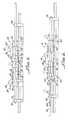
- FIG. 1is a perspective view of one embodiment of the present invention generally showing a linear array of permanent magnets, a diamagnetic member for engaging in the magnetic flux provided by the permanent magnets, a mechanism for causing reciprocating movement of the diamagnetic member within the magnetic flux and coupling apparatus for engaging a vehicle axle in order to reciprocate the diamagnetic member within the magnetic field and retard the motion of the vehicle passing the mechanism;
- FIG. 2is a view of the system illustrated in FIG. 1 taken along the line 2 - 2 ;
- FIGS. 3-6illustrate operation of the system shown in FIGS. 1 and 2 ;
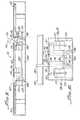
- FIG. 7is a perspective view of an alternative embodiment in accordance with the present invention generally showing a housing including a slot with a pair of dogs extending therethrough for coupling with a vehicle access shown in dashed line;
- FIG. 8is a plan view of the embodiment shown in FIG. 7 , sans the housing, showing a pair of spaced apart pulleys with a cable therebetween attached to dogs for moving a diamagnetic member through magnetic fields established by fixed magnets;
- FIG. 9is a side view of the apparatus shown in FIG. 8 taken along the line 9 - 9 showing spaced apart unlock and reset cams disposed in a spaced apart relationship for operation of the dogs as they are moved by a vehicle axle;
- FIG. 10is a view taken along line 10 - 10 of FIG. 8 showing an end view of the embodiment.
- FIG. 11is an enlarged view of a dog along with coupling apparatus interconnected to the dog diamagnetic member and cable along with the ratchet and a dog reset cam for causing a ratchet to block the cam in an upright position for engaging axle.
- FIGS. 1-6there is shown a motion retarding system 10 in accordance with the present invention for retarding the motion of a vehicle (not shown) therepast by way of engaging a vehicle axle 12 or the like.
- the system 10includes permanent magnet linear arrays 16 , 18 , 20 , 22 along with diamagnetic members 28 , 30 for engaging magnetic flux established by the arrays 16 , 18 , 20 , 22 which results in a braking force between the linear arrays 16 , 18 , 20 , 22 and the diamagnetic members 28 , 30 .
- the diamagnetic membersare fixed to a shaft 34 supported by bearings 38 , 40 for reciprocation as will be hereinafter described in greater detail.
- a mechanism 44is provided for causing reciprocated movement of the shaft 34 and diamagnetic members 28 , 30 and includes a pair of spaced apart pulleys 48 , 50 .
- Coupling apparatus 54is provided and disposed in an operative relationship with the mechanism 44 for engaging the axle 12 , moving with respect to the mechanism 44 , in order to reciprocate the shaft 34 and diamagnetic members 28 , 30 .
- the coupling apparatus 54includes a plurality of spaced apart dogs 58 , 60 , 62 interconnected by a continuous belt 66 .
- the continuous belt 66 and dogs 58 , 60 , 62pass around each pulley 48 , 50 with one dog 60 being connected to the diamagnetic members 28 , through the shaft 34 by a link 70 .
- Any suitable support structure 72may be utilized to position the system 10 for engagement of the dogs 58 , 60 , 62 with the passing axle 12 .
- Magnetic support structure 74 , 76support corresponding magnet arrays 16 , 18 and 20 , 22 in a conventional manner with a slot 78 , 80 therebetween for establishing a magnetic flux therebetween through which the corresponding diamagnetic members 28 , 30 pass.
- FIGS. 3-6Operation of the system 10 and reciprocal movement of the shaft 34 and diamagnetic members 28 , 30 is illustrated in FIGS. 3-6 .
- the diamagnetic members 28 , 30are centered within the magnets as the axle 12 moving in a direction of an arrow 84 engages the dog 58 .
- the axle 12 pushing the dog 58indicated by the arrow 86 in FIG. 4 moves the shaft 34 and diamagnetic members 28 , 30 to the position illustrated in FIG. 4 and arrow 88 .
- FIG. 7there is shown an alternative embodiment motion retarding system 110 generally showing a housing 112 for enclosing a mechanism 116 , shown in FIG. 8 , causing reciprocal movement of diamagnetic members 120 , 122 with magnetic field established by permanent magnet arrays 124 , 126 , 128 , 130 .
- Coupling apparatus 134 , 136includes dogs 140 , 142 extending through housing slots 144 , 146 as illustrated in FIG. 7 for engaging a vehicle axle 150 shown in phantom line in FIG. 7 .
- the mechanism 116shown in FIG. 8 , includes linkage 154 for enabling movement of one dog 140 engaging the vehicle axle 150 to cause movement of an unengaged dog 142 in an opposite direction to a direction of traffic vehicle indicated by the arrow 158 in FIG. 7 .
- the linkage 154includes a continuous cable 160 interconnecting the dogs 140 , 142 by way of the coupling apparatus 134 , 136 , with the cable 160 being supported by two spaced apart pulleys 164 , 166 and idlers 168 , 170 , 172 , 174 that cooperate with the pulleys 164 , 166 respectively to provide parallel linear sections of the cable 160 .
- the coupling apparatus 134 , 136includes dog housings 178 , 180 for coupling the dogs 140 , 142 to the cable 160 as well as the diamagnetic members 120 , 122 as shown in FIGS. 9 , 10 , 11 .
- the dog 140is pivotally mounted to the dog housing 178 by a pivot 184 and a ratchet 186 is fixed to the dog 144 for rotation therewith about the pin 184 .
- the ratchet 186includes a notch 190 for engaging with a pivot arm 194 to lock the dog 140 in an upright position for engagement with the axle 150 . Rotation of the dog and ratchet 186 being caused by a reset cam 196 as the dog 140 is moved to the position shown in FIG. 9 with the dog housing 78 being moved along slide member supports 200 on slide members 202 as shown in FIG. 10 .
- the reset cam 196is disposed proximate the pulley 164 .
- a ratchet unlike unlock cam 206engages the pivot arm 194 illustrated in phantom line in FIG. 9 to rotate the pivot arm away from the ratchet notch 190 thus enabling the dog 140 to recline as represented by the recline dog 142 in FIG. 7 .
- the dogs 140 , 142thus travel back and forth through the slots 144 , 146 and the mechanism 160 , herein described, reciprocates the diamagnetic members 120 , 122 through the magnetic fields established by the magnet arrays 124 , 126 , 128 which may be disposed in magnet housings 210 , 212 , see FIG. 10 .
- a method for retarding motion of a vehicleis provided by the system 10 , 110 .
Landscapes
- Engineering & Computer Science (AREA)
- Power Engineering (AREA)
- Transportation (AREA)
- Mechanical Engineering (AREA)
- Dynamo-Electric Clutches, Dynamo-Electric Brakes (AREA)
Abstract
Description
Claims (4)
Priority Applications (2)
| Application Number | Priority Date | Filing Date | Title |
|---|---|---|---|
| US11/869,629US7984796B2 (en) | 2006-10-13 | 2007-10-09 | Motion retarding system and method |
| PCT/US2007/080926WO2008048834A2 (en) | 2006-10-13 | 2007-10-10 | Motion retarding system and method |
Applications Claiming Priority (2)
| Application Number | Priority Date | Filing Date | Title |
|---|---|---|---|
| US85146406P | 2006-10-13 | 2006-10-13 | |
| US11/869,629US7984796B2 (en) | 2006-10-13 | 2007-10-09 | Motion retarding system and method |
Publications (2)
| Publication Number | Publication Date |
|---|---|
| US20080087510A1 US20080087510A1 (en) | 2008-04-17 |
| US7984796B2true US7984796B2 (en) | 2011-07-26 |
Family
ID=39302162
Family Applications (1)
| Application Number | Title | Priority Date | Filing Date |
|---|---|---|---|
| US11/869,629Expired - Fee RelatedUS7984796B2 (en) | 2006-10-13 | 2007-10-09 | Motion retarding system and method |
Country Status (2)
| Country | Link |
|---|---|
| US (1) | US7984796B2 (en) |
| WO (1) | WO2008048834A2 (en) |
Cited By (11)
| Publication number | Priority date | Publication date | Assignee | Title |
|---|---|---|---|---|
| US8851235B2 (en) | 2009-03-10 | 2014-10-07 | Eddy Current Limited Partnership | Braking mechanisms |
| US10020720B2 (en) | 2014-08-18 | 2018-07-10 | Eddy Current Limited Partnership | Latching devices |
| US10110089B2 (en) | 2014-08-18 | 2018-10-23 | Eddy Current Limited Partnership | Tuning of a kinematic relationship between members |
| US10300397B2 (en) | 2013-12-16 | 2019-05-28 | Eddy Current Limited Partnership | Assembly to control or govern relative speed of movement between parts |
| US10498210B2 (en) | 2014-08-18 | 2019-12-03 | Eddy Current Limited Partnership | Tuning of a kinematic relationship between members |
| US10693360B2 (en) | 2014-12-04 | 2020-06-23 | Eddy Current Limited Partnership | Transmissions incorporating eddy current braking |
| US10774887B2 (en) | 2014-12-04 | 2020-09-15 | Eddy Current Limited Partnership | Latch activation between members |
| US10940339B2 (en) | 2014-12-04 | 2021-03-09 | Eddy Current Limited Partnership | Energy absorbing apparatus |
| US10953848B2 (en) | 2015-12-18 | 2021-03-23 | Eddy Current Limited Partnership | Variable behavior control mechanism for a motive system |
| US11050336B2 (en) | 2014-12-04 | 2021-06-29 | Eddy Current Limited Partnership | Methods of altering eddy current interactions |
| US11114930B2 (en) | 2014-12-04 | 2021-09-07 | Eddy Current Limited Partnership | Eddy current brake configurations |
Families Citing this family (4)
| Publication number | Priority date | Publication date | Assignee | Title |
|---|---|---|---|---|
| US8037978B1 (en)* | 2007-03-13 | 2011-10-18 | Daniel Boren | Eddy current braking system for trolley zip line cable |
| CN107206978B (en) | 2014-08-20 | 2020-06-02 | 特鲁布鲁有限公司 | Eddy current braking device for rotating system |
| US10052910B2 (en) | 2015-11-10 | 2018-08-21 | Uremet Corporation | Illuminated system for use with amusement rides |
| EP4031254B1 (en) | 2019-09-20 | 2025-07-09 | Trublue LLC | Lock-off descent control systems and devices |
Citations (4)
| Publication number | Priority date | Publication date | Assignee | Title |
|---|---|---|---|---|
| US5628385A (en) | 1995-07-26 | 1997-05-13 | Mitsubishi Denki Kabushiki Kaisha | Elevator overspeed protection apparatus |
| US6360669B1 (en) | 1999-02-04 | 2002-03-26 | Innova Patent Gmbh | Installation for moving persons from a mountain station into a valley station |
| US20020117378A1 (en) | 2001-02-07 | 2002-08-29 | Denipro Ag | Conveyor system |
| US20040262103A1 (en) | 2001-11-23 | 2004-12-30 | Peter Rosner | Popular amusement device with switchable eddy-current brake |
- 2007
- 2007-10-09USUS11/869,629patent/US7984796B2/ennot_activeExpired - Fee Related
- 2007-10-10WOPCT/US2007/080926patent/WO2008048834A2/enactiveApplication Filing
Patent Citations (4)
| Publication number | Priority date | Publication date | Assignee | Title |
|---|---|---|---|---|
| US5628385A (en) | 1995-07-26 | 1997-05-13 | Mitsubishi Denki Kabushiki Kaisha | Elevator overspeed protection apparatus |
| US6360669B1 (en) | 1999-02-04 | 2002-03-26 | Innova Patent Gmbh | Installation for moving persons from a mountain station into a valley station |
| US20020117378A1 (en) | 2001-02-07 | 2002-08-29 | Denipro Ag | Conveyor system |
| US20040262103A1 (en) | 2001-11-23 | 2004-12-30 | Peter Rosner | Popular amusement device with switchable eddy-current brake |
Cited By (26)
| Publication number | Priority date | Publication date | Assignee | Title |
|---|---|---|---|---|
| US10518115B2 (en) | 2009-03-10 | 2019-12-31 | Eddy Current Limited Partnership | Braking mechanisms |
| US12268904B2 (en) | 2009-03-10 | 2025-04-08 | Eddy Current Limited Partnership | Braking mechanisms |
| US10065054B2 (en) | 2009-03-10 | 2018-09-04 | Eddy Current Limited Partnership | Braking mechanisms |
| US8851235B2 (en) | 2009-03-10 | 2014-10-07 | Eddy Current Limited Partnership | Braking mechanisms |
| US11628373B2 (en) | 2013-12-16 | 2023-04-18 | Eddy Current Limited Partnership | Assembly to control or govern relative speed of movement between parts |
| US11266917B2 (en) | 2013-12-16 | 2022-03-08 | Eddy Current Limited Partnership | Assembly to control or govern relative speed of movement between parts |
| US10300397B2 (en) | 2013-12-16 | 2019-05-28 | Eddy Current Limited Partnership | Assembly to control or govern relative speed of movement between parts |
| US10603596B2 (en) | 2013-12-16 | 2020-03-31 | Eddy Current Limited Partnership | Assembly to control or govern relative speed of movement between parts |
| US10020720B2 (en) | 2014-08-18 | 2018-07-10 | Eddy Current Limited Partnership | Latching devices |
| US11735992B2 (en) | 2014-08-18 | 2023-08-22 | Eddy Current Limited Partnership | Tuning of a kinematic relationship between members |
| US10498210B2 (en) | 2014-08-18 | 2019-12-03 | Eddy Current Limited Partnership | Tuning of a kinematic relationship between members |
| US10110089B2 (en) | 2014-08-18 | 2018-10-23 | Eddy Current Limited Partnership | Tuning of a kinematic relationship between members |
| US11515776B2 (en) | 2014-08-18 | 2022-11-29 | Eddy Current Limited Partnership | Tuning of a kinematic relationship between members |
| US10940339B2 (en) | 2014-12-04 | 2021-03-09 | Eddy Current Limited Partnership | Energy absorbing apparatus |
| US11114930B2 (en) | 2014-12-04 | 2021-09-07 | Eddy Current Limited Partnership | Eddy current brake configurations |
| US11050336B2 (en) | 2014-12-04 | 2021-06-29 | Eddy Current Limited Partnership | Methods of altering eddy current interactions |
| US11499596B2 (en) | 2014-12-04 | 2022-11-15 | Eddy Current Limited Partnership | Latch activation between members |
| US11009089B2 (en) | 2014-12-04 | 2021-05-18 | Eddy Current Limited Partnership | Latch activation between members |
| US10774887B2 (en) | 2014-12-04 | 2020-09-15 | Eddy Current Limited Partnership | Latch activation between members |
| US11777391B2 (en) | 2014-12-04 | 2023-10-03 | Eddy Current Limited Partnership | Methods of altering eddy current interactions |
| US11992713B2 (en) | 2014-12-04 | 2024-05-28 | Eddy Current Limited Partnership | Energy absorbing apparatus |
| US12009721B2 (en) | 2014-12-04 | 2024-06-11 | Eddy Current Limited Partnership | Eddy current brake configurations |
| US10693360B2 (en) | 2014-12-04 | 2020-06-23 | Eddy Current Limited Partnership | Transmissions incorporating eddy current braking |
| US12281681B2 (en) | 2014-12-04 | 2025-04-22 | Surewerx Usa, Inc. | Latch activation between members |
| US10953848B2 (en) | 2015-12-18 | 2021-03-23 | Eddy Current Limited Partnership | Variable behavior control mechanism for a motive system |
| US11878651B2 (en) | 2015-12-18 | 2024-01-23 | Eddy Current Limited Partnership | Variable behavior control mechanism for a motive system |
Also Published As
| Publication number | Publication date |
|---|---|
| WO2008048834A9 (en) | 2009-01-15 |
| US20080087510A1 (en) | 2008-04-17 |
| WO2008048834A2 (en) | 2008-04-24 |
| WO2008048834A3 (en) | 2008-11-27 |
Similar Documents
| Publication | Publication Date | Title |
|---|---|---|
| US7984796B2 (en) | Motion retarding system and method | |
| US6899036B2 (en) | Apparatus, systems and methods for levitating and moving objects | |
| KR100913682B1 (en) | Apparatus, systems, and methods for lifting and moving goods | |
| US6523650B1 (en) | Permanent magnet eddy brake with flux-steering poles | |
| US8025131B1 (en) | Eddy current braking system for trolley zip line cable with a stationary conductor | |
| US6918469B1 (en) | Curvilinear eddy current braking apparatus | |
| WO2001038123A1 (en) | Apparatus including eddy current braking system | |
| CN110589394B (en) | Rotary connecting rod type double-layer crossed belt sorting system | |
| CN1114629A (en) | A conveying system | |
| EP3471996B1 (en) | Magnetic suspension for a vehicle | |
| CN105346555A (en) | Brake clamp device of magnetic levitation vehicle | |
| CN111646085A (en) | Annular shuttle with three-wheel structure | |
| JP2013159469A (en) | Device of transferring and sorting articles | |
| CN219905793U (en) | Conveying device and production line | |
| CN109057460B (en) | Intelligent carrier | |
| CN107804128B (en) | Trolley | |
| CN211001348U (en) | Fixed-point parking device of mine car | |
| US3083650A (en) | Conveyors | |
| CN209480559U (en) | Protrusion-dispelling convert to guide wheel device, sorting trolley and halved belt sorter | |
| CN110562656A (en) | Turnover device for 180-degree vertical turnover | |
| AU2007254643B2 (en) | Apparatus, systems and methods for levitating and moving objects | |
| CN1537796A (en) | Mixed drive conveyor | |
| US3372652A (en) | Railway car moving device | |
| CN119160569B (en) | Transport vehicle for transferring stacker to switch between multiple lanes and transfer method thereof | |
| JP2007097308A (en) | Normal conducting suction type magnetic levitation vehicle |
Legal Events
| Date | Code | Title | Description |
|---|---|---|---|
| AS | Assignment | Owner name:MAGNETAR TECHNOLOGIES CORP, CALIFORNIA Free format text:ASSIGNMENT OF ASSIGNORS INTEREST;ASSIGNOR:EDWARD M. PRIBONIC;REEL/FRAME:019959/0035 Effective date:20071009 | |
| STCF | Information on status: patent grant | Free format text:PATENTED CASE | |
| FPAY | Fee payment | Year of fee payment:4 | |
| SULP | Surcharge for late payment | ||
| AS | Assignment | Owner name:EDWARD M. PRIBONIC, P.E., INC., CALIFORNIA Free format text:ASSIGNMENT OF ASSIGNORS INTEREST;ASSIGNOR:MAGNETAR TECHNOLOGIES CORP.;REEL/FRAME:036963/0645 Effective date:20150925 | |
| MAFP | Maintenance fee payment | Free format text:PAYMENT OF MAINTENANCE FEE, 8TH YR, SMALL ENTITY (ORIGINAL EVENT CODE: M2552); ENTITY STATUS OF PATENT OWNER: SMALL ENTITY Year of fee payment:8 | |
| FEPP | Fee payment procedure | Free format text:MAINTENANCE FEE REMINDER MAILED (ORIGINAL EVENT CODE: REM.); ENTITY STATUS OF PATENT OWNER: SMALL ENTITY | |
| LAPS | Lapse for failure to pay maintenance fees | Free format text:PATENT EXPIRED FOR FAILURE TO PAY MAINTENANCE FEES (ORIGINAL EVENT CODE: EXP.); ENTITY STATUS OF PATENT OWNER: SMALL ENTITY | |
| STCH | Information on status: patent discontinuation | Free format text:PATENT EXPIRED DUE TO NONPAYMENT OF MAINTENANCE FEES UNDER 37 CFR 1.362 | |
| FP | Lapsed due to failure to pay maintenance fee | Effective date:20230726 |