US7983617B2 - Method and system for transmitting multiple channels on FM bands - Google Patents
Method and system for transmitting multiple channels on FM bandsDownload PDFInfo
- Publication number
- US7983617B2 US7983617B2US11/936,156US93615607AUS7983617B2US 7983617 B2US7983617 B2US 7983617B2US 93615607 AUS93615607 AUS 93615607AUS 7983617 B2US7983617 B2US 7983617B2
- Authority
- US
- United States
- Prior art keywords
- radio frequency
- signals
- baseband
- signal
- frequency
- Prior art date
- Legal status (The legal status is an assumption and is not a legal conclusion. Google has not performed a legal analysis and makes no representation as to the accuracy of the status listed.)
- Active, expires
Links
Images


Classifications
- H—ELECTRICITY
- H03—ELECTRONIC CIRCUITRY
- H03L—AUTOMATIC CONTROL, STARTING, SYNCHRONISATION OR STABILISATION OF GENERATORS OF ELECTRONIC OSCILLATIONS OR PULSES
- H03L7/00—Automatic control of frequency or phase; Synchronisation
- H03L7/06—Automatic control of frequency or phase; Synchronisation using a reference signal applied to a frequency- or phase-locked loop
- H03L7/08—Details of the phase-locked loop
- H03L7/085—Details of the phase-locked loop concerning mainly the frequency- or phase-detection arrangement including the filtering or amplification of its output signal
- H—ELECTRICITY
- H03—ELECTRONIC CIRCUITRY
- H03L—AUTOMATIC CONTROL, STARTING, SYNCHRONISATION OR STABILISATION OF GENERATORS OF ELECTRONIC OSCILLATIONS OR PULSES
- H03L7/00—Automatic control of frequency or phase; Synchronisation
- H03L7/06—Automatic control of frequency or phase; Synchronisation using a reference signal applied to a frequency- or phase-locked loop
- H03L7/16—Indirect frequency synthesis, i.e. generating a desired one of a number of predetermined frequencies using a frequency- or phase-locked loop
- H03L7/18—Indirect frequency synthesis, i.e. generating a desired one of a number of predetermined frequencies using a frequency- or phase-locked loop using a frequency divider or counter in the loop
- H03L7/181—Indirect frequency synthesis, i.e. generating a desired one of a number of predetermined frequencies using a frequency- or phase-locked loop using a frequency divider or counter in the loop a numerical count result being used for locking the loop, the counter counting during fixed time intervals
Definitions
- Certain embodiments of the inventionrelate to signal processing for communication systems. More specifically, certain embodiments of the invention relate to a method and system for transmitting multiple channels on FM bands.
- a method and/or system for transmitting multiple channels on FM bandssubstantially as shown in and/or described in connection with at least one of the figures, as set forth more completely in the claims.
- FIG. 1is a block diagram illustrating an exemplary FM transceiver system, in accordance with an embodiment of the invention.
- FIG. 2is a frequency diagram illustrating an exemplary FM transmitter frequency band, in accordance with an embodiment of the invention.
- FIG. 3is a block diagram illustrating an exemplary FM transmitter system, in accordance with an embodiment of the invention.
- FIG. 4Ais a circuit diagram illustrating an exemplary embodiment of a dual channel FM transmitter, in accordance with an embodiment of the invention.
- FIG. 4Bis a block diagram of an exemplary Hybrid Analog/Digital (HD) FM transmitter, in accordance with an embodiment of the invention.
- FIG. 4Cis a circuit diagram illustrating an exemplary embodiment of a dual channel FM transmitter using digital IF modulation, in accordance with an embodiment of the invention.
- FIG. 4Dis a block diagram of an exemplary Hybrid Analog/Digital (HD) FM transmitter using digital IF modulation, in accordance with an embodiment of the invention.
- HDHybrid Analog/Digital
- FIG. 5is a flow chart illustrating an exemplary FM transmission process, in accordance with an embodiment of the invention.
- Certain embodiments of the inventionmay be found in a method and system for transmitting multiple channels on FM bands. Aspects of the invention may comprise generating from one or more baseband signals, a plurality of radio frequency transmission signals each at a different radio frequency, wherein the one or more baseband signals comprise an in-phase signal component and/or a quadrature signal component. Suitable combinations of the one or more baseband signals may be modulated in a radio frequency transmission chain that may comprise intermediate frequency modulation and radio frequency modulation. The suitable combinations of the one or more baseband signals may be weighted sums. The plurality of radio frequency signals may each carry distinct information.
- One of the plurality of radio frequency signalsmay be centered at a frequency f 1 +f 2 and another one of said plurality of radio frequency signals may be centered at a frequency f 1 ⁇ f 2 , where f 1 and f 2 are frequencies.
- the frequencies f 1 and f 2may correspond to the radio frequency modulation and the intermediate frequency modulation.
- the plurality of radio frequency transmission signalsmay be frequency modulated signals.
- a plurality of intermediate frequency signal componentsmay be summed and perform the radio frequency modulation on the sum of the plurality of intermediate frequency signal components.
- a plurality of radio frequency signal componentsmay be summed to obtain the plurality of radio frequency transmission signals.
- the suitable combinations of the one or more baseband signalsmay be up-converted to radio frequency signals.
- FIG. 1is a block diagram illustrating an exemplary FM transceiver system, in accordance with an embodiment of the invention. Referring to FIG. 1 , there is shown an FM transceiver system 100 comprising an antenna 102 , a coupler 104 , an FM receiver 150 , an FM transmitter 180 and a device control 106 .
- the FM transceiver system 100may comprise suitable logic, circuitry and/or code that may be enabled to transmit and receive FM signals simultaneously on different frequencies and/or in an alternating fashion on the same frequency.
- the FM transmitter 180may comprise suitable logic, circuitry and/or code to enable generation of a transmit signal that may be communicated to the coupler 104 .
- the FM receiver 150may comprise suitable logic, circuitry and/or logic that may enable reception and/or processing of FM signals, fed to it from the coupler 104 .
- the antenna 102may be a shared antenna for a transmit signal path and a receive signal path.
- the transmit signal path from the FM transmitter 180 and the receive signal path to the FM receiver 150may be coupled to the antenna 102 at the coupler 104 that may comprise suitable logic, circuitry and/or code to join the receive signal path and the transmit signal path, in order to communicatively couple a common signal path to antenna 102 .
- a device control block 106may comprise suitable logic, circuitry and/or code to enable controlling the FM transmitter 180 and the FM receiver 150 .
- the control block 106may control, for example, a gain and/or a demodulation frequency in the FM receiver 150 and, for example, a transmit power and frequency of the FM transmitter 180 .
- the functionality of the device control block 106may not be limited to the functionality described above.
- the FM transceiver system 100may not comprise an FM receiver 150 ; and/or the FM receiver 150 and the FM transmitter 180 may use separate antennas.
- the FM transceiver system 100may be a stand-alone system or may form part of a device, for example, a personal audio player or a cellular mobile phone. The invention may not be limited to the examples given above.
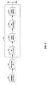
- FIG. 2is a frequency diagram illustrating an exemplary FM transmitter frequency band, in accordance with an embodiment of the invention.
- a baseband spectrum 204with a baseband center frequency 202
- an intermediate frequency (IF) spectrum 208with an IF center frequency 206
- a radio frequency (RF) spectrum 212with an RF center frequency 210 .
- IFintermediate frequency
- RFradio frequency
- a baseband signalmay be generated, which may generally comprise low-frequency signal components. Most signal processing may generally take place at low signal frequencies since practical implementation of low-frequency components may be desirable.
- the baseband signalmay be, for example, an FM-modulated stereo audio signals such as music or speech.
- the baseband spectrum 204may depict an exemplary frequency band of a baseband signal.
- the baseband spectrum 204may, for example, indicate the signal power as a function of frequency.
- the baseband signalmay typically be band-limited, that is, most of the signal energy may be concentrated in a limited band of frequencies. For example, high quality audio may be concentrated between 20 Hz and 15 kHz or telephone quality voice may be concentrated between 400 Hz and 3400 Hz.
- the baseband signalmay need to be shifted to higher frequencies that may be more amenable to radio transmission. For example, most FM radio stations broadcast at frequencies near 100 MHz.
- frequency translation of the baseband spectrum 212 to the RF spectrum 212may be achieved via an intermediate frequency spectrum 208 .
- the intermediate frequency spectrummay be at a fixed frequency, whereas the RF frequency for transmission may be variable.
- certain signal processingmay occur at the intermediate frequency.
- One advantage of thismay be that the characteristics of the processing blocks at IF may be more narrowband than they may need to be at the higher RF frequencies. In other words, it may be desirable for most components to be tuned to operate over a narrow range of frequencies.
- the frequency translation to intermediate frequency and the frequency translation to radio frequencymay typically require appropriate filters to reject image frequencies.
- Image frequenciesmay in some cases be undesired frequency components that may arise from the modulation process and may be reduced by appropriate filtering.
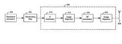
- FIG. 3is a block diagram illustrating an exemplary FM transmitter system, in accordance with an embodiment of the invention.
- a baseband processor 302a baseband processor 302 , a band-limiting filter 304 , an RF transmitter chain 306 and an antenna 308 .
- the RF transmitter chain 306may comprise an IF modulation block 310 , image rejection blocks 312 and 316 , and RF modulation block 314 .
- the baseband processor 302may comprise suitable logic, circuitry and/or code that may be enabled to generate a baseband signal, which may comprise an in-phase and/or a quadrature component.
- the baseband signal generated in the baseband processor 302may be communicatively coupled to the band-limiting filter 304 .
- the baseband processor 302 and the band-limiting filter 304may generate a signal spectrum similar to, for example, the baseband spectrum 204 shown in FIG. 2 .
- the filtered baseband signalmay be modulated to intermediate frequency (IF) in the IF modulation block 310 .
- the image rejection block 312may comprise suitable logic, circuitry and/or code that may be enabled to reduce undesirable IF signal components.
- the output signal of the image rejection block 312may be coupled to the RF modulation block 314 .
- the RF modulation block 314may comprise suitable logic, circuitry and/or code that may be enabled to modulate the filtered IF signal to radio frequency.
- the image rejection block 316may comprise suitable logic, circuitry and/or code that may be enabled to reduce undesired RF frequency components.
- the output signal of the RF transmitter chain 306may be communicatively fed to the antenna 308 , where the RF signal may be transmitted from.
- RDSRadio Data System
- RBDSRadio Broadcast Data System
- RDS/RBDSmay be used to send certain data embedded in an FM radio broadcast.
- RDS/RBDSmay comprise a transmit station identifier (PI) and alternate frequencies (AF identifier). Based on the station identifier and alternate frequency information, the FM radio receiver may switch to a better reception quality frequency without interrupting the reception for the listener.
- PItransmit station identifier
- AF identifieralternate frequencies
- the FM radio receivermay switch to a better reception quality frequency without interrupting the reception for the listener.
- a traveling carfor example, may seamlessly switch from radio transmitter to radio transmitter that may provide good and uninterrupted reception quality to the listener as the vehicle travels through the coverage area of various radio transmitters.
- a baseband signal generated in the baseband processor 302may comprise information that may enable a suitable FM receiver to automatically change to the best quality reception frequency.
- a portable, low-power FM transmitterthat may be used, for example, to broadcast audio from a personal audio player for reception by an FM receiver inside a vehicle
- an FM transmittermay desire to transmit multiple channels at several different frequencies, so that the FM receiver may switch between the at least two channels, based on which broadcast may be desired.
- Such a transmission signalmay be generated, in accordance with an embodiment of the invention.
- the signals x I (t) and x Q (t)may be generated from modulating suitable sums of the baseband signal components s I1 (t), s I2 (t), s Q1 (t) and s Q2 (t) onto an in-phase carrier cos(w a t) and a quadrature carrier sin(w a t).
- an image frequency rejectionmay not be desirable in this instance, as illustrated in equation (2).
- the generated channelmay be generated at frequencies given by the set ⁇ w 1 ⁇ w 2 ⁇ . . . ⁇ w K ⁇ .
- the amplitude of each channelmay be adjusted independently from the other channels by appropriately adjusting the amplitude to the base signals s I1 (t), s I2 (t), s Q1 (t) and s Q2 (t).
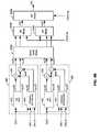
- FIG. 4Ais a circuit diagram illustrating an exemplary embodiment of a dual channel FM transmitter, in accordance with an embodiment of the invention.
- the baseband mixermay comprise adders 408 , 410 , 412 and 414 .
- the RF mixer 404may comprise multipliers 416 and 418 and adder 420 .
- the RF mixer 434may comprise multipliers 422 , 424 and adder 426 .
- the RF mixer 406may comprise multipliers 428 and 430 , adder 434 and amplifier 432 .
- the RF mixers 404 , 434 and 406may be substantially similar and may comprise suitable logic, circuitry and/or code that may be enabled to accept an in-phase input signal and a quadrature input signal and modulate them onto a carrier signal, respectively.
- the baseband mixer 402may comprise suitable logic, circuitry and/or code that may be enabled to generate output signals that may be suitable sums of a plurality of input signals.
- FIG. 4Amay illustrate a circuit implementation of equation (2).
- the baseband mixer 402may generate the various combinations of baseband input signals s I1 (t), s I2 (t), s Q1 (t) and s Q2 (t), which may be modulated in the RF mixers 404 and 434 .
- RF mixer 404may generate x I (t), in accordance with equation (2).
- RF mixer 434may generate x Q (t), in accordance with equation (2).
- the outputs of the RF mixers 404 and 434may be communicatively coupled to RF mixer 406 , which may generate s(t).
- the RF mixers 404 and 434may also be referred to as an intermediate frequency modulator and the RF mixer 406 may be referred to as the radio frequency modulator.
- FIG. 4Bis a block diagram of an exemplary Hybrid Analog/Digital (HD) FM transmitter, in accordance with an embodiment of the invention.
- a first channel processor 440may comprise a FM DAC 442 , a compress OFDM DAC 444 and adders 446 and 448 .
- the second channel processor 450may comprise a FM DAC 452 , a compress OFDM DAC 454 and adders 456 and 458 There is also shown a digital audio input DA 1 , a plurality of digital audio inputs DA 1 . 1 through DA 1 .N, a digital audio input DA 2 , a plurality of digital audio inputs DA 2 .
- baseband signals s aI 1 ( t ), s aQ1 ( 1 ), s dI1 (t), s dQ1 (t), s aI2 (t), s aQ2 (t), s dI2 (t), and s dQ2 (t)baseband signals s I1 (t), s Q1 (t), s I2 (t), and s Q2 (t), intermediate frequency signals x I (t) and x Q (t) and RF signal s(t).
- the baseband mixer 402 b and the RF mixers 404 b , 434 b and 406 bmay be substantially similar to the corresponding elements in FIG. 4A , baseband mixer 402 and the RF mixers 404 , 434 and 406 , respectively.
- the baseband processors 440 and 450may be substantially similar and may comprise suitable, logic, circuitry and/or code that may be enabled to convert a plurality of digital audio stream to a hybrid analog FM signal comprising an in-phase and a quadrature component.
- the baseband processor 440may be coupled to digital audio input DA 1 using, for example, a PCM format.
- the input DA 1may in some cases also be an analog signal.
- the digital audio signal DA 1may be encoded by both the FM DAC 442 and the compress OFDM DAC.
- the digital audio signals DA 1 . 1 through DA 1 .Nmay be encoded digitally in the compress OFDM DAC 444 .
- the digital audio signal DA 2may be encoded by the FM DAC 452 and the compress OFDM DAC 454 , and the digital audio signals DA 2 . 1 through DA 2 .N may be encoded digitally in the compress OFDM DAC 454 .
- the digital audio signals DA 1 and DA 2may hence be hybrid encoded.
- the digital audio signals DA 1 . 1 through DA 1 .N and the digital audio signals DA 2 . 1 through DA 2 .Nmay be encoded HD digitally.
- the digital audio signal DA 1may then be communicatively coupled to the input of the FM DAC 442 .
- the FM DAC 442may comprise suitable circuitry, logic and/or code that may be enabled to convert the input signal to an analog frequency-modulated (FM) signal comprising of an in-phase baseband signal s aI (t) and a quadrature baseband signal s aQ1 (t).
- FMfrequency-modulated
- the output signals of the FM DAC 442may in some instances conform to standard FM broadcast formats.
- the digital audio input DA 1may also be communicatively coupled to the Compress OFDM DAC 444 .
- the compress OFDM DAC 444may comprise suitable circuitry, logic and/or code that may be enabled to generate an analog OFDM modulated output signal that may be used for Hybrid Analog/Digital (HD) FM broadcasts, for example.
- the output of the compress OFDM DAC 444may comprise an in-phase output s d1I (t) and a quadrature output s dQ1 (t).
- the compress OFDM DA 444 convertermay convert the plurality of digital audio inputs DA 1 , and DA 1 . 1 through DA 1 .N, for example, by first compressing the audio digitally, OFDM modulate it and finally convert it to an analog signal.
- the second channel processor 450may be substantially similar and may generate an in-phase and a quadrature output signal similar to the first channel processor 440 for the digital audio input DA 2 , and DA 2 .
- the baseband in-phase and quadrature componentsmay be communicatively coupled to the baseband mixer 402 b , where suitable summing of the input signals may occur in order to generate the output signals of the base band mixer 402 b , as described for FIG. 4A .
- the RF mixers 404 b and 434 bmay generate an intermediate frequency signal, comprising an in-phase component x I (t) and a quadrature component x Q (t).
- the outputs from the RF mixers 404 b and 434 bmay be upconverted and summed to generate an output signal s(t), as described for FIG. 4A .
- This signalin accordance with various embodiments of the invention, may comprise a plurality of radio channels, which may be HD FM channels, for example, as illustrated in FIG. 4B .
- FIG. 4Cis a circuit diagram illustrating an exemplary embodiment of a dual channel FM transmitter using digital IF modulation, in accordance with an embodiment of the invention.
- a baseband mixer 402 cmay comprise adders 408 c , 410 c , 412 c and 414 c , multipliers 416 c , 418 c , 422 c and 424 c , and adders 420 c and 426 c .
- the DAC block 440 cmay comprise a DAC 442 c and a DAC 444 c .
- the DAC 442 c and the DAC 444 cmay be substantially similar and may comprise suitable logic, circuitry and/or code that may be enabled to accept an digital in-phase input signal and a digital quadrature input signal and convert them to an analog output signal suitable for RF modulation in the RF mixer block 406 c .
- the baseband mixer 402 cmay comprise suitable logic, circuitry and/or code that may be enabled to generate digital output signals that may be suitable sums of a plurality of digital input signals that may be modulated digitally to intermediate frequency.
- FIG. 4Cmay illustrate a digital implementation of equation (2).
- the baseband mixer 402 cmay generate the various combinations of baseband input signals s I1 (t), s I2 (t), s Q1 (t) and s Q2 (t), which may be modulated to intermediate frequency by the multipliers 416 c , 418 c , 422 c and 424 c .
- the operations in baseband mixer 402 cmay be digital, and may generate digital output signals x I (t) and x Q (t), in accordance with equation (2).
- the digital IF modulated outputs of the baseband mixer 402 cmay be communicatively coupled to the DAC block 440 c , which may generate analog signals suitable for RF modulation.
- the output signals of the DAC 442 c and the DAC 444 cmay be communicatively coupled to the RF mixer 406 c , where the signals may be modulated to radio frequency and combined to generate s(t).
- FIG. 4Dis a block diagram of an exemplary Hybrid Analog/Digital (HD) FM transmitter using digital IF modulation, in accordance with an embodiment of the invention.
- a digital processor 480may comprise a first channel processor 440 d , a second channel processor 450 d and a baseband mixer 402 d .
- the first channel processor 440 dmay comprise an FM modulator 442 d , an OFDM modulator 444 d and adders 446 d and 448 d .
- the second channel processor 450 dmay comprise an FM modulator 452 d , an OFDM modulator 454 d and adders 456 d and 458 d There is also shown a digital audio input DA 1 , a plurality of digital audio inputs DA 1 . 1 through DA 1 .N, a digital audio input DA 2 , a plurality of digital audio inputs DA 2 .
- baseband signals s aI (t), s aQ1 ( 1 ), s dI1 (t), s dQ1 (t), s aI2 (t), s aQ2 (t), s dI2 (t), and s dQ2 (t)baseband signals s I1 (t), s Q1 (t), s I2 (t), and s Q2 (t), intermediate frequency signals x I (t) and x Q (t) and RF signal s(t).
- the digital processor functionality 480may be substantially similar, but digitally implemented, to the functionality of the first channel processor 440 , second channel processor 450 , baseband mixer 402 b , and RF mixers 404 b and 434 b illustrated in FIG. 4B .
- the baseband mixer 402 d and the DACs 404 d and 434 dmay be substantially similar to the corresponding elements in FIG. 4C , baseband mixer 402 c and DACs 442 c and 444 c , respectively.
- the baseband first channel processors 440 d and 450 dmay be similar and may comprise suitable, logic, circuitry and/or code that may be enabled to convert a plurality of digital audio stream to a hybrid digital FM signal comprising an in-phase and a quadrature component.
- the baseband processor 440 dmay be coupled to digital audio input DA 1 using, for example, a PCM format.
- the digital audio signal DA 1may be encoded by both the FM modulator 442 d and the OFDM modulator 444 d .
- the digital audio signals DA 1 . 1 through DA 1 .Nmay be encoded digitally in the OFDM modulator 444 d .
- the digital audio signal DA 2may be encoded by the FM modulator 452 d and the OFDM modulator 454 d , and the digital audio signals DA 2 . 1 through DA 2 .N may be encoded digitally in the OFDM modulator 454 d .
- the digital audio signals DA 1 and DA 2may hence be hybrid encoded.
- the digital audio signals DA 1 . 1 through DA 1 .N and the digital audio signals DA 2 . 1 through DA 2 .Nmay be encoded HD digitally.
- the digital audio signal DA 1may be communicatively coupled to the input of the FM modulator 442 d .
- the FM modulator 442 dmay comprise suitable circuitry, logic and/or code that may be enabled to convert the input signal to a digital frequency-modulated (FM) signal comprising of an in-phase baseband signal s aI1 (t) and a quadrature baseband signal s aQ1 (t).
- the output signals of the FM modulator 442 dmay in some instances conform to standard FM broadcast formats.
- the digital audio input DA 1may also be communicatively coupled to the OFDM modulator 444 d .
- the OFDM modulator 444 dmay comprise suitable circuitry, logic and/or code that may be enabled to generate a digital OFDM modulated output signal that may be used for Hybrid Analog/Digital (HD) FM broadcasts, for example.
- the output of the OFDM modulator 444 dmay comprise an in-phase output s dI1 (t) and a quadrature output s dQ1 (t).
- the OFDM modulator 444 dmay convert the plurality of digital audio inputs DA 1 , and DA 1 . 1 through DA 1 .N, for example, by first compressing the audio digitally, and OFDM modulate it.
- the second channel processor 450 dmay be substantially similar and may generate an in-phase and a quadrature output signal similar to the first channel processor 440 d for the digital audio input DA 2 , and DA 2 .
- the baseband in-phase and quadrature componentsmay be communicatively coupled to the baseband mixer 402 d , where suitable summing of the input signals may occur in order to generate the output signals of the baseband mixer 402 d , as described for FIG. 4C .
- the DAC 404 d and 434 dmay convert a digital intermediate frequency signal, comprising an in-phase component x I (t) and a quadrature component x Q (t), to an analog signal suitable for RF modulation in the RF mixer 406 d .
- the outputs from the DACs 404 c and 434 dmay be upconverted and summed to generate an output signal s(t), as described for FIG. 4C .
- This signalin accordance with various embodiments of the invention, may comprise a plurality of radio channels, which may be HD FM channels, for example, as illustrated in FIG. 4D .
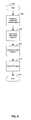
- FIG. 5is a flow chart illustrating an exemplary FM transmission process, in accordance with an embodiment of the invention.
- the FM transmission processmay initially start by generating a plurality of band-limited baseband signal in step 504 , for example s I1 (t), s I2 (t), s Q1 (t) and s Q2 (t).
- the band-limited baseband signalsmay comprise in-phase and/or quadrature signal components.
- the band-limited baseband signals that may be generated in step 504may be upconverted to intermediate frequency in step 506 . This may be achieved through modulation onto, for example, a carrier at frequency w b of appropriate sums of the baseband signals.
- the upconversion to radio frequency in step 508may be achieved by upconverting intermediate frequency signal components.
- the RF signalmay then be transmitted, for example, over an antenna similar to antenna 308 , illustrated in FIG. 3 .
- a method and system for transmitting multiple channels on FM bandsmay comprise generating from one or more baseband signals, a plurality of radio frequency transmission signals each at a different radio frequency, as shown for s(t) in FIG. 3 , wherein the one or more baseband signals comprise an in-phase signal component, for example s I1 (t) and/or a quadrature signal component, for example s Q2 (t).
- Suitable combinations of the one or more baseband signals, for example s I1 (t)+s I2 (t)may be modulated in a radio frequency transmission chain as illustrated in FIG. 3 and FIG.
- the suitable combinations of the one or more baseband signalsmay be weighted sums.
- the plurality of radio frequency signalsmay each carry distinct information, due to the different baseband signal combinations that may be carried.
- One of the plurality of radio frequency signalsmay be centered at a frequency f 1 +f 2 and another one of said plurality of radio frequency signals may be centered at a frequency f 1 ⁇ f 2 , where f 1 and f 2 are frequencies.
- the frequencies f 1 and f 2may correspond to the radio frequency modulation and the intermediate frequency modulation, as illustrated in FIG. 4A .
- the plurality of radio frequency transmission signalsmay be frequency modulated signals, for example s(t).
- a plurality of intermediate frequency signal componentsfor example in the RF mixer 404 may be summed and perform the radio frequency modulation on the sum of the plurality of intermediate frequency signal components, for example in the RF mixer 406 .
- a plurality of radio frequency signal componentsmay be summed to obtain the plurality of radio frequency transmission signals, for example at adder 434 in the RF mixer 406 .
- the suitable combinations of the one or more baseband signalsmay be up-converted to radio frequency signals.
- Another embodiment of the inventionmay provide a machine-readable storage, having stored thereon, a computer program having at least one code section executable by a machine, thereby causing the machine to perform the steps as described herein for transmitting multiple channels on FM bands.
- the present inventionmay be realized in hardware, software, or a combination of hardware and software.
- the present inventionmay be realized in a centralized fashion in at least one computer system, or in a distributed fashion where different elements are spread across several interconnected computer systems. Any kind of computer system or other apparatus adapted for carrying out the methods described herein is suited.
- a typical combination of hardware and softwaremay be a general-purpose computer system with a computer program that, when being loaded and executed, controls the computer system such that it carries out the methods described herein.
- the present inventionmay also be embedded in a computer program product, which comprises all the features enabling the implementation of the methods described herein, and which when loaded in a computer system is able to carry out these methods.
- Computer program in the present contextmeans any expression, in any language, code or notation, of a set of instructions intended to cause a system having an information processing capability to perform a particular function either directly or after either or both of the following: a) conversion to another language, code or notation; b) reproduction in a different material form.
Landscapes
- Transmitters (AREA)
- Transceivers (AREA)
- Stabilization Of Oscillater, Synchronisation, Frequency Synthesizers (AREA)
Abstract
Description
s′(t)=sI(t)cos(w1t)+sQ(t)sin(w1t)
where sI(t) may be the in-phase baseband component and sQ(t) may be a quadrature baseband component and w1=2πf1may be the angular frequency that may define the carrier frequency at radio frequency. In accordance with an embodiment of the invention, an FM transmitter may desire to transmit multiple channels at several different frequencies, so that the FM receiver may switch between the at least two channels, based on which broadcast may be desired. In this case, the desired transmitted signal may be similar to s(t), given by the following relationship for two channels at different frequencies:
s(t)=sI1(t)cos(w1t)+sQ1(t)sin(w1t)+sI2(t)cos(w2t)+sQ2(t)sin(w2t) (1)
where baseband signals sI1(t) and sQ1(t), and sI2(t) and sQ2(t) may be transmitted on angular frequencies w1and w2, respectively. In some instances, sI1(t)=sI2(t) and sQ1(t)=sQ2(t), so that the two transmit channels depicted in equation (1) may be the same. Such a transmission signal may be generated, in accordance with an embodiment of the invention.
Based on equation (2), the desired signal s(t) may written in the form of a bandpass signal, as may be seen from line 2 of equation (2), whereby the in-phase signal xI(t) and the quadrature signal sQ(t) may be themselves bandpass signals. As illustrated in equation (2), the signals xI(t) and xQ(t) may be generated from modulating suitable sums of the baseband signal components sI1(t), sI2(t), sQ1(t) and sQ2(t) onto an in-phase carrier cos(wat) and a quadrature carrier sin(wat). In accordance with various embodiments of the invention, an image frequency rejection may not be desirable in this instance, as illustrated in equation (2). The exemplary embodiment of the invention illustrated above may be used to generate more than two bandpass channels as illustrated above. For example, N=2K−1different channels may be generated from K different frequencies. It may be observed that, for example, the generated channel may be generated at frequencies given by the set {w1±w2± . . . ±wK}. The amplitude of each channel may be adjusted independently from the other channels by appropriately adjusting the amplitude to the base signals sI1(t), sI2(t), sQ1(t) and sQ2(t).
sI1(t)=saI1(t)+sdI1(t)
sQ1(t)=saQ1(t)+sdQ1(t)
The
sI2(t)=saI2(t)+sdI2(t)
sQ2(t)=saQ2(t)+sdQ2(t)
sI1(t)=saI1(t)+sdI1(t)
sQ1(t)=saQ1(t)+sdQ1(t)
The
sI2(t)=saI2(t)+sdI2(t)
sQ2(t)=saQ2(t)+sdQ2(t)
Claims (18)
Priority Applications (1)
| Application Number | Priority Date | Filing Date | Title |
|---|---|---|---|
| US11/936,156US7983617B2 (en) | 2007-03-19 | 2007-11-07 | Method and system for transmitting multiple channels on FM bands |
Applications Claiming Priority (2)
| Application Number | Priority Date | Filing Date | Title |
|---|---|---|---|
| US89566507P | 2007-03-19 | 2007-03-19 | |
| US11/936,156US7983617B2 (en) | 2007-03-19 | 2007-11-07 | Method and system for transmitting multiple channels on FM bands |
Publications (2)
| Publication Number | Publication Date |
|---|---|
| US20080233882A1 US20080233882A1 (en) | 2008-09-25 |
| US7983617B2true US7983617B2 (en) | 2011-07-19 |
Family
ID=39774089
Family Applications (19)
| Application Number | Title | Priority Date | Filing Date |
|---|---|---|---|
| US11/781,787AbandonedUS20080233869A1 (en) | 2007-03-19 | 2007-07-23 | Method and system for a single-chip fm tuning system for transmit and receive antennas |
| US11/831,399Expired - Fee RelatedUS7586378B2 (en) | 2007-03-19 | 2007-07-31 | Method and system for using a frequency locked loop logen in oscillator systems |
| US11/832,598Expired - Fee RelatedUS7917115B2 (en) | 2007-03-19 | 2007-08-01 | Method and system for auto detecting and auto switching antennas in a multi-antenna FM transmit/receive system |
| US11/832,488AbandonedUS20080233911A1 (en) | 2007-03-19 | 2007-08-01 | Method and system for utilizing a power source as an fm antenna for an integrated fm radio |
| US11/832,498AbandonedUS20080232447A1 (en) | 2007-03-19 | 2007-08-01 | Method and system for calibration in an fm transceiver system |
| US11/832,468Expired - Fee RelatedUS7925220B2 (en) | 2007-03-19 | 2007-08-01 | Method and system for matching an integrated FM system to an antenna utilizing on-chip measurement of reflected signals |
| US11/832,590Active2029-09-20US8208886B2 (en) | 2007-03-19 | 2007-08-01 | Method and system for optimizing an FM transmitter and FM receiver in a single chip FM transmitter and FM receiver system |
| US11/832,609Expired - Fee RelatedUS7792502B2 (en) | 2007-03-19 | 2007-08-01 | Method and system for measuring and optimizing integrated antenna performance |
| US11/832,858AbandonedUS20080233954A1 (en) | 2007-03-19 | 2007-08-02 | Method And System For Processing Results Derived From Detecting Channels Suitable For FM Transmission In An Integrated FM Transmit/Receive System |
| US11/832,844Expired - Fee RelatedUS8027641B2 (en) | 2007-03-19 | 2007-08-02 | Method and system for detecting channels suitable for FM transmission in an integrated FM transmit/receive system |
| US11/839,345AbandonedUS20080233900A1 (en) | 2007-03-19 | 2007-08-15 | Method and system for calibration in an fm transceiver system with off-chip control |
| US11/846,989AbandonedUS20080233907A1 (en) | 2007-03-19 | 2007-08-29 | Method And System For Determining Channel Spacing And Configuring An FM Transmitter |
| US11/853,705AbandonedUS20080232523A1 (en) | 2007-03-19 | 2007-09-11 | Method And System For Mixing A Plurality Of Audio Sources In An FM Transmitter |
| US11/855,217Active2029-12-09US7974590B2 (en) | 2007-03-19 | 2007-09-14 | Method and system for simultaneous signal transmission on multiple selected frequencies |
| US11/936,156Active2030-05-02US7983617B2 (en) | 2007-03-19 | 2007-11-07 | Method and system for transmitting multiple channels on FM bands |
| US12/837,102Expired - Fee RelatedUS8391810B2 (en) | 2007-03-19 | 2010-07-15 | Method and system for measuring and optimizing integrated antenna performance |
| US13/071,651AbandonedUS20110171916A1 (en) | 2007-03-19 | 2011-03-25 | Auto Detecting and Auto Switching Antennas in a Mutli-Antenna FM Transmit/Receive System |
| US13/080,316Expired - Fee RelatedUS8270907B2 (en) | 2007-03-19 | 2011-04-05 | Method and system for matching an integrated FM system to an antenna utilizing on-chip measurement of reflected signals |
| US13/176,664Expired - Fee RelatedUS8467745B2 (en) | 2007-03-19 | 2011-07-05 | Method and system for simultaneous signal transmission on multiple selected frequencies |
Family Applications Before (14)
| Application Number | Title | Priority Date | Filing Date |
|---|---|---|---|
| US11/781,787AbandonedUS20080233869A1 (en) | 2007-03-19 | 2007-07-23 | Method and system for a single-chip fm tuning system for transmit and receive antennas |
| US11/831,399Expired - Fee RelatedUS7586378B2 (en) | 2007-03-19 | 2007-07-31 | Method and system for using a frequency locked loop logen in oscillator systems |
| US11/832,598Expired - Fee RelatedUS7917115B2 (en) | 2007-03-19 | 2007-08-01 | Method and system for auto detecting and auto switching antennas in a multi-antenna FM transmit/receive system |
| US11/832,488AbandonedUS20080233911A1 (en) | 2007-03-19 | 2007-08-01 | Method and system for utilizing a power source as an fm antenna for an integrated fm radio |
| US11/832,498AbandonedUS20080232447A1 (en) | 2007-03-19 | 2007-08-01 | Method and system for calibration in an fm transceiver system |
| US11/832,468Expired - Fee RelatedUS7925220B2 (en) | 2007-03-19 | 2007-08-01 | Method and system for matching an integrated FM system to an antenna utilizing on-chip measurement of reflected signals |
| US11/832,590Active2029-09-20US8208886B2 (en) | 2007-03-19 | 2007-08-01 | Method and system for optimizing an FM transmitter and FM receiver in a single chip FM transmitter and FM receiver system |
| US11/832,609Expired - Fee RelatedUS7792502B2 (en) | 2007-03-19 | 2007-08-01 | Method and system for measuring and optimizing integrated antenna performance |
| US11/832,858AbandonedUS20080233954A1 (en) | 2007-03-19 | 2007-08-02 | Method And System For Processing Results Derived From Detecting Channels Suitable For FM Transmission In An Integrated FM Transmit/Receive System |
| US11/832,844Expired - Fee RelatedUS8027641B2 (en) | 2007-03-19 | 2007-08-02 | Method and system for detecting channels suitable for FM transmission in an integrated FM transmit/receive system |
| US11/839,345AbandonedUS20080233900A1 (en) | 2007-03-19 | 2007-08-15 | Method and system for calibration in an fm transceiver system with off-chip control |
| US11/846,989AbandonedUS20080233907A1 (en) | 2007-03-19 | 2007-08-29 | Method And System For Determining Channel Spacing And Configuring An FM Transmitter |
| US11/853,705AbandonedUS20080232523A1 (en) | 2007-03-19 | 2007-09-11 | Method And System For Mixing A Plurality Of Audio Sources In An FM Transmitter |
| US11/855,217Active2029-12-09US7974590B2 (en) | 2007-03-19 | 2007-09-14 | Method and system for simultaneous signal transmission on multiple selected frequencies |
Family Applications After (4)
| Application Number | Title | Priority Date | Filing Date |
|---|---|---|---|
| US12/837,102Expired - Fee RelatedUS8391810B2 (en) | 2007-03-19 | 2010-07-15 | Method and system for measuring and optimizing integrated antenna performance |
| US13/071,651AbandonedUS20110171916A1 (en) | 2007-03-19 | 2011-03-25 | Auto Detecting and Auto Switching Antennas in a Mutli-Antenna FM Transmit/Receive System |
| US13/080,316Expired - Fee RelatedUS8270907B2 (en) | 2007-03-19 | 2011-04-05 | Method and system for matching an integrated FM system to an antenna utilizing on-chip measurement of reflected signals |
| US13/176,664Expired - Fee RelatedUS8467745B2 (en) | 2007-03-19 | 2011-07-05 | Method and system for simultaneous signal transmission on multiple selected frequencies |
Country Status (1)
| Country | Link |
|---|---|
| US (19) | US20080233869A1 (en) |
Families Citing this family (278)
| Publication number | Priority date | Publication date | Assignee | Title |
|---|---|---|---|---|
| US8744384B2 (en) | 2000-07-20 | 2014-06-03 | Blackberry Limited | Tunable microwave devices with auto-adjusting matching circuit |
| TW200602577A (en) | 2004-04-22 | 2006-01-16 | Swagelok Co | Fitting for tube and pipe |
| US7750685B1 (en)* | 2005-03-17 | 2010-07-06 | Rf Micro Devices, Inc. | Frequency measurement based frequency locked loop synthesizer |
| US7932784B1 (en) | 2005-03-17 | 2011-04-26 | Rf Micro Devices, Inc. | Frequency and phase locked loop synthesizer |
| US9406444B2 (en) | 2005-11-14 | 2016-08-02 | Blackberry Limited | Thin film capacitors |
| US7711337B2 (en) | 2006-01-14 | 2010-05-04 | Paratek Microwave, Inc. | Adaptive impedance matching module (AIMM) control architectures |
| TWI292257B (en)* | 2006-03-09 | 2008-01-01 | Wistron Corp | Wireless communication module capable of switching an internal antenna module and an external antenna module |
| US7574187B2 (en)* | 2006-05-30 | 2009-08-11 | Sony Ericsson Mobile Communications Ab | Battery charger antenna, method and device incorporating the same |
| US7714676B2 (en) | 2006-11-08 | 2010-05-11 | Paratek Microwave, Inc. | Adaptive impedance matching apparatus, system and method |
| US7535312B2 (en) | 2006-11-08 | 2009-05-19 | Paratek Microwave, Inc. | Adaptive impedance matching apparatus, system and method with improved dynamic range |
| US8036308B2 (en)* | 2007-02-28 | 2011-10-11 | Broadcom Corporation | Method and system for a wideband polar transmitter |
| US20080233869A1 (en)* | 2007-03-19 | 2008-09-25 | Thomas Baker | Method and system for a single-chip fm tuning system for transmit and receive antennas |
| US7683851B2 (en)* | 2007-03-19 | 2010-03-23 | Broadcom Corporation | Method and system for using a single transformer for FM transmit and FM receive functions |
| US7917104B2 (en) | 2007-04-23 | 2011-03-29 | Paratek Microwave, Inc. | Techniques for improved adaptive impedance matching |
| US8213886B2 (en) | 2007-05-07 | 2012-07-03 | Paratek Microwave, Inc. | Hybrid techniques for antenna retuning utilizing transmit and receive power information |
| WO2008155595A1 (en)* | 2007-06-18 | 2008-12-24 | Nokia Corporation | Method and device for continuation of multimedia playback |
| US20100054746A1 (en) | 2007-07-24 | 2010-03-04 | Eric Raymond Logan | Multi-port accumulator for radio-over-fiber (RoF) wireless picocellular systems |
| US8942645B2 (en)* | 2010-09-30 | 2015-01-27 | Broadcom Corporation | Method and system for communication via subbands in a 60 GHZ distributed communication system |
| US8942647B2 (en)* | 2010-09-30 | 2015-01-27 | Broadcom Corporation | Method and system for antenna switching for 60 GHz distributed communication |
| JP5363490B2 (en)* | 2007-10-02 | 2013-12-11 | オープンピーク インコーポレイテッド | System and method for interprocessor communication |
| US8175459B2 (en) | 2007-10-12 | 2012-05-08 | Corning Cable Systems Llc | Hybrid wireless/wired RoF transponder and hybrid RoF communication system using same |
| US20090117857A1 (en)* | 2007-11-02 | 2009-05-07 | Broadcom Corporation | FM radio devices determining preferred inactive FM radio channel for communication |
| US20090122749A1 (en)* | 2007-11-13 | 2009-05-14 | Joonbum Byun | Method and apparatus for localizing AM/FM/XM radio advertisement |
| US7991363B2 (en) | 2007-11-14 | 2011-08-02 | Paratek Microwave, Inc. | Tuning matching circuits for transmitter and receiver bands as a function of transmitter metrics |
| US7941194B2 (en)* | 2007-11-16 | 2011-05-10 | Silicon Laboratories Inc. | Antenna co-location in portable devices for simultaneous receive and transmit |
| US8718561B2 (en) | 2007-11-20 | 2014-05-06 | Aruba Networks, Inc. | Method and apparatus for detecting and avoiding interference in a communications network |
| KR101397035B1 (en)* | 2007-11-30 | 2014-05-20 | 엘지전자 주식회사 | Terminal and method of supporting broadcasting technology therein |
| US20090238158A1 (en)* | 2008-03-20 | 2009-09-24 | Infineon Technologies Ag | Packet Fragment Adaptation for Improved Coexistence |
| US20090247101A1 (en)* | 2008-03-28 | 2009-10-01 | Ligang Zhang | Auto-detection of broadcast channel spacing |
| US8478218B2 (en)* | 2008-06-11 | 2013-07-02 | Quintic Holdings | Frequency modulation (FM) clear channel scanning system and method of using same |
| US20100009631A1 (en)* | 2008-06-12 | 2010-01-14 | Griffin Jr Paul P | Transmitting accessory utilizing power system transmission |
| US8315578B2 (en)* | 2008-07-15 | 2012-11-20 | Research In Motion Limited | Mobile wireless communications device with separate in-phase and quadrature power amplification |
| US8072285B2 (en) | 2008-09-24 | 2011-12-06 | Paratek Microwave, Inc. | Methods for tuning an adaptive impedance matching network with a look-up table |
| US20100105340A1 (en)* | 2008-10-29 | 2010-04-29 | Qualcomm Incorporated | Interface for wireless communication devices |
| US8285233B2 (en)* | 2008-12-18 | 2012-10-09 | Nokia Corporation | Method for displaying other stations now playing list |
| US8682261B2 (en)* | 2009-02-13 | 2014-03-25 | Qualcomm Incorporated | Antenna sharing for wirelessly powered devices |
| US8422588B2 (en)* | 2009-04-01 | 2013-04-16 | Intel Mobile Communications GmbH | Variable-size mixer for high gain range transmitter |
| US8270921B2 (en)* | 2009-04-27 | 2012-09-18 | Csr Technology Inc. | Systems and methods for tuning an antenna for a frequency modulation transceiver |
| US8326233B2 (en)* | 2009-05-11 | 2012-12-04 | Broadcom Corporation | Method and system for a configurable tuned MOS capacitor |
| US8295788B2 (en)* | 2009-06-09 | 2012-10-23 | Broadcom Corporation | Method and system for an N-phase transmitter utilizing a leaky wave antenna |
| DE102009033673B4 (en)* | 2009-07-17 | 2015-12-24 | Qualcomm Technologies, Inc. (N.D.Ges.D. Staates Delaware) | Adaptively tuned matching network with improved linear behavior |
| KR101086569B1 (en)* | 2009-08-13 | 2011-11-23 | 엘지이노텍 주식회사 | Impedance regulator of adaptive tuning antenna circuit |
| US8472888B2 (en)* | 2009-08-25 | 2013-06-25 | Research In Motion Rf, Inc. | Method and apparatus for calibrating a communication device |
| US9503017B1 (en) | 2009-09-29 | 2016-11-22 | Qorvo Us, Inc. | Infrastructure-grade integrated voltage controlled oscillator (VCO) with linear tuning characteristics and low phase noise |
| US9026062B2 (en) | 2009-10-10 | 2015-05-05 | Blackberry Limited | Method and apparatus for managing operations of a communication device |
| US8774743B2 (en)* | 2009-10-14 | 2014-07-08 | Blackberry Limited | Dynamic real-time calibration for antenna matching in a radio frequency receiver system |
| US8208884B2 (en)* | 2009-10-28 | 2012-06-26 | Silicon Laboratories Inc. | Method and system for FM tuner ground isolation when using ground signal line as FM antenna |
| CN102612813A (en)* | 2009-11-16 | 2012-07-25 | 诺基亚公司 | A processor, apparatus and associated methods |
| US8559383B2 (en)* | 2009-11-20 | 2013-10-15 | Nokia Corporation | Multiradio control |
| US8825037B2 (en) | 2009-12-22 | 2014-09-02 | Starkey Laboratories, Inc. | FM radio system for digital and analog communications for hearing assistance devices |
| US8421408B2 (en)* | 2010-01-23 | 2013-04-16 | Sotoudeh Hamedi-Hagh | Extended range wireless charging and powering system |
| US20110181408A1 (en)* | 2010-01-28 | 2011-07-28 | Paul Gailey Greenis | Public Tactical Message System |
| US8718576B2 (en)* | 2010-02-11 | 2014-05-06 | Mediatek Inc. | Radio frequency modulator and method thereof |
| US8954011B2 (en)* | 2010-02-19 | 2015-02-10 | Broadcom Corporation | Method and system for a wireless integrated test and measurement device |
| US8803631B2 (en) | 2010-03-22 | 2014-08-12 | Blackberry Limited | Method and apparatus for adapting a variable impedance network |
| US8442577B2 (en)* | 2010-03-30 | 2013-05-14 | Mediatek Inc. | Wireless communication apparatus with an antenna shared between a plurality of communication circuits |
| KR101637211B1 (en)* | 2010-04-12 | 2016-07-08 | 삼성전자 주식회사 | Portable terminal and method for operating of mimo antenna thereof |
| JP5901612B2 (en) | 2010-04-20 | 2016-04-13 | ブラックベリー リミテッド | Method and apparatus for managing interference in a communication device |
| US8238924B2 (en) | 2010-04-30 | 2012-08-07 | The United States Of America As Represented By The Secretary Of The Navy | Real-time optimization of allocation of resources |
| TWI504063B (en)* | 2010-06-02 | 2015-10-11 | Chiun Mai Comm Systems Inc | System and method for antenna switching |
| US8548408B2 (en) | 2010-06-11 | 2013-10-01 | Panasonic Automotive Systems Company Of America, Division Of Panasonic Corporation Of North America | Method and apparatus for utilizing modulation based audio correlation technique for maintaining dynamic FM station list in single tuner variant and assisting alternate frequency switching methodology in single tuner and dual tuner variants |
| CN103296367B (en) | 2010-07-29 | 2016-02-10 | 天工方案公司 | Electricity container is made to reduce coupling coefficient change |
| CN101924834B (en)* | 2010-08-17 | 2013-07-03 | 惠州Tcl移动通信有限公司 | Method for using handle rope of fixed wireless phone as FM antenna and fixed wireless phone |
| US8572304B2 (en)* | 2010-09-28 | 2013-10-29 | Wellala, Inc. | Systems and methods for configuring mobile devices for printing to wireless printers |
| DE102010043031A1 (en)* | 2010-10-28 | 2012-05-03 | Endress + Hauser Flowtec Ag | Field device e.g. sensor for e.g. level measuring device, has antenna that is connected to conductor attachment structure, so that radio signal corresponding to electromagnetic signal is received over conductor attachment structure |
| US9379454B2 (en) | 2010-11-08 | 2016-06-28 | Blackberry Limited | Method and apparatus for tuning antennas in a communication device |
| US8686736B2 (en) | 2010-11-23 | 2014-04-01 | Infineon Technologies Ag | System and method for testing a radio frequency integrated circuit |
| US8712340B2 (en) | 2011-02-18 | 2014-04-29 | Blackberry Limited | Method and apparatus for radio antenna frequency tuning |
| US8655286B2 (en) | 2011-02-25 | 2014-02-18 | Blackberry Limited | Method and apparatus for tuning a communication device |
| CN102118838B (en)* | 2011-03-21 | 2013-11-06 | 惠州Tcl移动通信有限公司 | Frequency modulation (FM) channel-searching method of mobile phone and mobile phone |
| US8515416B2 (en)* | 2011-04-29 | 2013-08-20 | Silicon Laboratories Inc | Performing testing in a radio device |
| US8811906B2 (en) | 2011-05-13 | 2014-08-19 | Sierra Wireless, Inc. | Apparatus and method for multi-signal interference-avoiding data transmission |
| WO2012156988A2 (en)* | 2011-05-13 | 2012-11-22 | Indian Institute Of Technology, Bombay | Low power analog fm transceiver for bio-telemetry applications |
| US8626083B2 (en) | 2011-05-16 | 2014-01-07 | Blackberry Limited | Method and apparatus for tuning a communication device |
| US8594584B2 (en) | 2011-05-16 | 2013-11-26 | Blackberry Limited | Method and apparatus for tuning a communication device |
| KR101828302B1 (en)* | 2011-06-24 | 2018-03-22 | 삼성전자 주식회사 | Providing Method For Radio Channel List And Portable Device supporting the same |
| EP2740221B1 (en) | 2011-08-05 | 2019-06-26 | BlackBerry Limited | Method and apparatus for band tuning in a communication device |
| US8676116B2 (en) | 2011-10-07 | 2014-03-18 | Blackberry Limited | Electronic device with NFC antenna adjacent display and related methods |
| US8660612B2 (en) | 2011-10-07 | 2014-02-25 | Blackberry Limited | Electronic device having an NFC antenna in a speaker compartment and related methods |
| US9197467B2 (en) | 2011-10-21 | 2015-11-24 | Itron, Inc. | Multiple protocol receiver |
| US20130099938A1 (en)* | 2011-10-21 | 2013-04-25 | Itron, Inc. | Software-defined communication unit |
| US8837640B2 (en) | 2011-10-21 | 2014-09-16 | Itron, Inc. | Multiple protocol receiver |
| US9292782B2 (en)* | 2011-10-26 | 2016-03-22 | Qualcomm Incorporated | Adaptive NFC transceivers |
| US9331723B2 (en) | 2011-11-14 | 2016-05-03 | Blackberry Limited | Perturbation-based dynamic measurement of antenna impedance in real-time |
| US8412167B1 (en) | 2011-12-08 | 2013-04-02 | Sprint Communications Company L.P. | Wireless communication system that selects and broadcasts FM media streams on a per-base station basis |
| US8627162B2 (en)* | 2011-12-12 | 2014-01-07 | International Business Machines Corporation | Iimplementing enhanced aperture function calibration for logic built in self test (LBIST) |
| TWI514675B (en)* | 2012-01-19 | 2015-12-21 | Wistron Neweb Corp | Antenna apparatus and antenna switch circuit |
| US20130257667A1 (en)* | 2012-03-30 | 2013-10-03 | Broadcom Corporation | Antenna Tuning |
| WO2013170226A1 (en)* | 2012-05-10 | 2013-11-14 | Eden Rock Communications, Llc | Method and system for auditing and correcting cellular antenna coverage patterns |
| US8648634B2 (en) | 2012-05-10 | 2014-02-11 | International Business Machines Corporation | Input jitter filter for a phase-locked loop (PLL) |
| US8948889B2 (en) | 2012-06-01 | 2015-02-03 | Blackberry Limited | Methods and apparatus for tuning circuit components of a communication device |
| US9859797B1 (en) | 2014-05-07 | 2018-01-02 | Energous Corporation | Synchronous rectifier design for wireless power receiver |
| US10148097B1 (en) | 2013-11-08 | 2018-12-04 | Energous Corporation | Systems and methods for using a predetermined number of communication channels of a wireless power transmitter to communicate with different wireless power receivers |
| US10230266B1 (en) | 2014-02-06 | 2019-03-12 | Energous Corporation | Wireless power receivers that communicate status data indicating wireless power transmission effectiveness with a transmitter using a built-in communications component of a mobile device, and methods of use thereof |
| US10211680B2 (en) | 2013-07-19 | 2019-02-19 | Energous Corporation | Method for 3 dimensional pocket-forming |
| US10186913B2 (en) | 2012-07-06 | 2019-01-22 | Energous Corporation | System and methods for pocket-forming based on constructive and destructive interferences to power one or more wireless power receivers using a wireless power transmitter including a plurality of antennas |
| US10211682B2 (en) | 2014-05-07 | 2019-02-19 | Energous Corporation | Systems and methods for controlling operation of a transmitter of a wireless power network based on user instructions received from an authenticated computing device powered or charged by a receiver of the wireless power network |
| US10270261B2 (en) | 2015-09-16 | 2019-04-23 | Energous Corporation | Systems and methods of object detection in wireless power charging systems |
| US10124754B1 (en) | 2013-07-19 | 2018-11-13 | Energous Corporation | Wireless charging and powering of electronic sensors in a vehicle |
| US10063106B2 (en) | 2014-05-23 | 2018-08-28 | Energous Corporation | System and method for a self-system analysis in a wireless power transmission network |
| US10206185B2 (en) | 2013-05-10 | 2019-02-12 | Energous Corporation | System and methods for wireless power transmission to an electronic device in accordance with user-defined restrictions |
| US9124125B2 (en) | 2013-05-10 | 2015-09-01 | Energous Corporation | Wireless power transmission with selective range |
| US9438045B1 (en) | 2013-05-10 | 2016-09-06 | Energous Corporation | Methods and systems for maximum power point transfer in receivers |
| US10038337B1 (en) | 2013-09-16 | 2018-07-31 | Energous Corporation | Wireless power supply for rescue devices |
| US9853458B1 (en) | 2014-05-07 | 2017-12-26 | Energous Corporation | Systems and methods for device and power receiver pairing |
| US10141768B2 (en) | 2013-06-03 | 2018-11-27 | Energous Corporation | Systems and methods for maximizing wireless power transfer efficiency by instructing a user to change a receiver device's position |
| US10224758B2 (en) | 2013-05-10 | 2019-03-05 | Energous Corporation | Wireless powering of electronic devices with selective delivery range |
| US9853363B2 (en) | 2012-07-06 | 2017-12-26 | Blackberry Limited | Methods and apparatus to control mutual coupling between antennas |
| US10103582B2 (en) | 2012-07-06 | 2018-10-16 | Energous Corporation | Transmitters for wireless power transmission |
| US10312715B2 (en) | 2015-09-16 | 2019-06-04 | Energous Corporation | Systems and methods for wireless power charging |
| US9843201B1 (en) | 2012-07-06 | 2017-12-12 | Energous Corporation | Wireless power transmitter that selects antenna sets for transmitting wireless power to a receiver based on location of the receiver, and methods of use thereof |
| US10291066B1 (en) | 2014-05-07 | 2019-05-14 | Energous Corporation | Power transmission control systems and methods |
| US9887584B1 (en) | 2014-08-21 | 2018-02-06 | Energous Corporation | Systems and methods for a configuration web service to provide configuration of a wireless power transmitter within a wireless power transmission system |
| US9871398B1 (en) | 2013-07-01 | 2018-01-16 | Energous Corporation | Hybrid charging method for wireless power transmission based on pocket-forming |
| US20150326070A1 (en) | 2014-05-07 | 2015-11-12 | Energous Corporation | Methods and Systems for Maximum Power Point Transfer in Receivers |
| US10141791B2 (en) | 2014-05-07 | 2018-11-27 | Energous Corporation | Systems and methods for controlling communications during wireless transmission of power using application programming interfaces |
| US10263432B1 (en) | 2013-06-25 | 2019-04-16 | Energous Corporation | Multi-mode transmitter with an antenna array for delivering wireless power and providing Wi-Fi access |
| US10063064B1 (en) | 2014-05-23 | 2018-08-28 | Energous Corporation | System and method for generating a power receiver identifier in a wireless power network |
| US10205239B1 (en) | 2014-05-07 | 2019-02-12 | Energous Corporation | Compact PIFA antenna |
| US10008889B2 (en) | 2014-08-21 | 2018-06-26 | Energous Corporation | Method for automatically testing the operational status of a wireless power receiver in a wireless power transmission system |
| US10965164B2 (en) | 2012-07-06 | 2021-03-30 | Energous Corporation | Systems and methods of wirelessly delivering power to a receiver device |
| US10199849B1 (en) | 2014-08-21 | 2019-02-05 | Energous Corporation | Method for automatically testing the operational status of a wireless power receiver in a wireless power transmission system |
| US11502551B2 (en) | 2012-07-06 | 2022-11-15 | Energous Corporation | Wirelessly charging multiple wireless-power receivers using different subsets of an antenna array to focus energy at different locations |
| US10992187B2 (en) | 2012-07-06 | 2021-04-27 | Energous Corporation | System and methods of using electromagnetic waves to wirelessly deliver power to electronic devices |
| US10256657B2 (en) | 2015-12-24 | 2019-04-09 | Energous Corporation | Antenna having coaxial structure for near field wireless power charging |
| US10128693B2 (en) | 2014-07-14 | 2018-11-13 | Energous Corporation | System and method for providing health safety in a wireless power transmission system |
| US10291055B1 (en) | 2014-12-29 | 2019-05-14 | Energous Corporation | Systems and methods for controlling far-field wireless power transmission based on battery power levels of a receiving device |
| US10211674B1 (en) | 2013-06-12 | 2019-02-19 | Energous Corporation | Wireless charging using selected reflectors |
| US10223717B1 (en) | 2014-05-23 | 2019-03-05 | Energous Corporation | Systems and methods for payment-based authorization of wireless power transmission service |
| US10193396B1 (en) | 2014-05-07 | 2019-01-29 | Energous Corporation | Cluster management of transmitters in a wireless power transmission system |
| US10090886B1 (en) | 2014-07-14 | 2018-10-02 | Energous Corporation | System and method for enabling automatic charging schedules in a wireless power network to one or more devices |
| US10218227B2 (en) | 2014-05-07 | 2019-02-26 | Energous Corporation | Compact PIFA antenna |
| US10090699B1 (en) | 2013-11-01 | 2018-10-02 | Energous Corporation | Wireless powered house |
| US9787103B1 (en) | 2013-08-06 | 2017-10-10 | Energous Corporation | Systems and methods for wirelessly delivering power to electronic devices that are unable to communicate with a transmitter |
| US10992185B2 (en) | 2012-07-06 | 2021-04-27 | Energous Corporation | Systems and methods of using electromagnetic waves to wirelessly deliver power to game controllers |
| US9812890B1 (en) | 2013-07-11 | 2017-11-07 | Energous Corporation | Portable wireless charging pad |
| US9825674B1 (en) | 2014-05-23 | 2017-11-21 | Energous Corporation | Enhanced transmitter that selects configurations of antenna elements for performing wireless power transmission and receiving functions |
| US12057715B2 (en) | 2012-07-06 | 2024-08-06 | Energous Corporation | Systems and methods of wirelessly delivering power to a wireless-power receiver device in response to a change of orientation of the wireless-power receiver device |
| US10381880B2 (en) | 2014-07-21 | 2019-08-13 | Energous Corporation | Integrated antenna structure arrays for wireless power transmission |
| US10243414B1 (en) | 2014-05-07 | 2019-03-26 | Energous Corporation | Wearable device with wireless power and payload receiver |
| US10199835B2 (en) | 2015-12-29 | 2019-02-05 | Energous Corporation | Radar motion detection using stepped frequency in wireless power transmission system |
| US10063105B2 (en) | 2013-07-11 | 2018-08-28 | Energous Corporation | Proximity transmitters for wireless power charging systems |
| US10439448B2 (en) | 2014-08-21 | 2019-10-08 | Energous Corporation | Systems and methods for automatically testing the communication between wireless power transmitter and wireless power receiver |
| US9867062B1 (en) | 2014-07-21 | 2018-01-09 | Energous Corporation | System and methods for using a remote server to authorize a receiving device that has requested wireless power and to determine whether another receiving device should request wireless power in a wireless power transmission system |
| US9876394B1 (en) | 2014-05-07 | 2018-01-23 | Energous Corporation | Boost-charger-boost system for enhanced power delivery |
| US10128699B2 (en) | 2014-07-14 | 2018-11-13 | Energous Corporation | Systems and methods of providing wireless power using receiver device sensor inputs |
| US9246223B2 (en) | 2012-07-17 | 2016-01-26 | Blackberry Limited | Antenna tuning for multiband operation |
| US9413066B2 (en) | 2012-07-19 | 2016-08-09 | Blackberry Limited | Method and apparatus for beam forming and antenna tuning in a communication device |
| US9350405B2 (en) | 2012-07-19 | 2016-05-24 | Blackberry Limited | Method and apparatus for antenna tuning and power consumption management in a communication device |
| US9362891B2 (en) | 2012-07-26 | 2016-06-07 | Blackberry Limited | Methods and apparatus for tuning a communication device |
| US9077426B2 (en) | 2012-10-31 | 2015-07-07 | Blackberry Limited | Adaptive antenna matching via a transceiver-based perturbation technique |
| US8913965B2 (en)* | 2012-11-19 | 2014-12-16 | Ixia | Methods, systems, and computer readable media for detecting antenna port misconfigurations |
| US9148796B2 (en)* | 2012-12-13 | 2015-09-29 | Ninve Jr. Inc. | Resilient antenna disturbance detector |
| US10404295B2 (en) | 2012-12-21 | 2019-09-03 | Blackberry Limited | Method and apparatus for adjusting the timing of radio antenna tuning |
| US9374113B2 (en) | 2012-12-21 | 2016-06-21 | Blackberry Limited | Method and apparatus for adjusting the timing of radio antenna tuning |
| US9077487B2 (en) | 2013-02-25 | 2015-07-07 | Itron, Inc. | Radio to support channel plans of arbitrary width and/or spacing |
| US9014307B2 (en) | 2013-02-25 | 2015-04-21 | Itron, Inc. | Radio to analog-to-digital sample rate decoupled from digital subsystem |
| US9426680B2 (en)* | 2013-02-25 | 2016-08-23 | Itron, Inc. | Real-time radio spectrum assessment engine |
| US9252998B2 (en) | 2013-02-25 | 2016-02-02 | Itron, Inc. | Radio to detect and compensate for frequency misalignment |
| US8885788B1 (en)* | 2013-05-15 | 2014-11-11 | Intel IP Corporation | Reducing settling time in phase-locked loops |
| TWI524705B (en)* | 2013-05-15 | 2016-03-01 | 瑞昱半導體股份有限公司 | Calibration method and calibration apparatus for communication system |
| US9379436B1 (en)* | 2013-05-24 | 2016-06-28 | The Boeing Company | Compensating for bit toggle error in phase shifters |
| US10103552B1 (en) | 2013-06-03 | 2018-10-16 | Energous Corporation | Protocols for authenticated wireless power transmission |
| US20140375515A1 (en)* | 2013-06-20 | 2014-12-25 | Blackberry Limited | Frequency tunable antenna |
| US10021523B2 (en) | 2013-07-11 | 2018-07-10 | Energous Corporation | Proximity transmitters for wireless power charging systems |
| US9504017B2 (en)* | 2013-09-27 | 2016-11-22 | Motorola Solutions, Inc. | Method and apparatus to increase service capacity in radio communication systems using idle working channels as flexible control channels |
| US10075017B2 (en) | 2014-02-06 | 2018-09-11 | Energous Corporation | External or internal wireless power receiver with spaced-apart antenna elements for charging or powering mobile devices using wirelessly delivered power |
| US10158257B2 (en) | 2014-05-01 | 2018-12-18 | Energous Corporation | System and methods for using sound waves to wirelessly deliver power to electronic devices |
| US10153653B1 (en) | 2014-05-07 | 2018-12-11 | Energous Corporation | Systems and methods for using application programming interfaces to control communications between a transmitter and a receiver |
| US10153645B1 (en) | 2014-05-07 | 2018-12-11 | Energous Corporation | Systems and methods for designating a master power transmitter in a cluster of wireless power transmitters |
| US10170917B1 (en) | 2014-05-07 | 2019-01-01 | Energous Corporation | Systems and methods for managing and controlling a wireless power network by establishing time intervals during which receivers communicate with a transmitter |
| US10566843B2 (en)* | 2014-07-15 | 2020-02-18 | Qorvo Us, Inc. | Wireless charging circuit |
| US10116143B1 (en) | 2014-07-21 | 2018-10-30 | Energous Corporation | Integrated antenna arrays for wireless power transmission |
| US10068703B1 (en) | 2014-07-21 | 2018-09-04 | Energous Corporation | Integrated miniature PIFA with artificial magnetic conductor metamaterials |
| US10559970B2 (en)* | 2014-09-16 | 2020-02-11 | Qorvo Us, Inc. | Method for wireless charging power control |
| KR20160055541A (en)* | 2014-11-10 | 2016-05-18 | 삼성전기주식회사 | Communication apparatus using multiple antennas |
| US9831960B2 (en) | 2014-12-05 | 2017-11-28 | Qualcomm Incorporated | Systems and methods for reducing transmission interference |
| US9438319B2 (en) | 2014-12-16 | 2016-09-06 | Blackberry Limited | Method and apparatus for antenna selection |
| US10122415B2 (en) | 2014-12-27 | 2018-11-06 | Energous Corporation | Systems and methods for assigning a set of antennas of a wireless power transmitter to a wireless power receiver based on a location of the wireless power receiver |
| US9531428B2 (en)* | 2015-03-03 | 2016-12-27 | Mediatek Inc. | Wireless communication calibration system and associated method |
| US9647706B2 (en)* | 2015-03-11 | 2017-05-09 | Nxp B.V. | Antenna tuning circuit |
| US9651582B2 (en) | 2015-03-11 | 2017-05-16 | Nxp B.V. | Integrated circuit device for impedance measurement |
| CN106033969B (en)* | 2015-03-12 | 2019-06-25 | 神讯电脑(昆山)有限公司 | Circuit for detecting and its method for detecting |
| US9954749B2 (en)* | 2015-03-17 | 2018-04-24 | Getac Technology Corporation | Detection circuit and detecting method thereof |
| EP3272141B1 (en)* | 2015-03-17 | 2018-12-26 | Telefonaktiebolaget LM Ericsson (PUBL) | Rssi measurement during lbt |
| CN104702698B (en)* | 2015-03-25 | 2019-01-25 | 杰克缝纫机股份有限公司 | Network terminal, sewing machine, and radio frequency-based multi-machine communication method and system |
| US9866336B2 (en) | 2015-06-17 | 2018-01-09 | Google Llc | Phased array antenna self-calibration |
| US10523033B2 (en) | 2015-09-15 | 2019-12-31 | Energous Corporation | Receiver devices configured to determine location within a transmission field |
| US12283828B2 (en) | 2015-09-15 | 2025-04-22 | Energous Corporation | Receiver devices configured to determine location within a transmission field |
| US10211685B2 (en) | 2015-09-16 | 2019-02-19 | Energous Corporation | Systems and methods for real or near real time wireless communications between a wireless power transmitter and a wireless power receiver |
| US10008875B1 (en) | 2015-09-16 | 2018-06-26 | Energous Corporation | Wireless power transmitter configured to transmit power waves to a predicted location of a moving wireless power receiver |
| US10778041B2 (en) | 2015-09-16 | 2020-09-15 | Energous Corporation | Systems and methods for generating power waves in a wireless power transmission system |
| US10199850B2 (en) | 2015-09-16 | 2019-02-05 | Energous Corporation | Systems and methods for wirelessly transmitting power from a transmitter to a receiver by determining refined locations of the receiver in a segmented transmission field associated with the transmitter |
| US10158259B1 (en) | 2015-09-16 | 2018-12-18 | Energous Corporation | Systems and methods for identifying receivers in a transmission field by transmitting exploratory power waves towards different segments of a transmission field |
| US11710321B2 (en) | 2015-09-16 | 2023-07-25 | Energous Corporation | Systems and methods of object detection in wireless power charging systems |
| US10186893B2 (en) | 2015-09-16 | 2019-01-22 | Energous Corporation | Systems and methods for real time or near real time wireless communications between a wireless power transmitter and a wireless power receiver |
| US9871387B1 (en) | 2015-09-16 | 2018-01-16 | Energous Corporation | Systems and methods of object detection using one or more video cameras in wireless power charging systems |
| US10135295B2 (en) | 2015-09-22 | 2018-11-20 | Energous Corporation | Systems and methods for nullifying energy levels for wireless power transmission waves |
| US10153660B1 (en) | 2015-09-22 | 2018-12-11 | Energous Corporation | Systems and methods for preconfiguring sensor data for wireless charging systems |
| US10050470B1 (en) | 2015-09-22 | 2018-08-14 | Energous Corporation | Wireless power transmission device having antennas oriented in three dimensions |
| US10128686B1 (en) | 2015-09-22 | 2018-11-13 | Energous Corporation | Systems and methods for identifying receiver locations using sensor technologies |
| US10020678B1 (en) | 2015-09-22 | 2018-07-10 | Energous Corporation | Systems and methods for selecting antennas to generate and transmit power transmission waves |
| US10033222B1 (en) | 2015-09-22 | 2018-07-24 | Energous Corporation | Systems and methods for determining and generating a waveform for wireless power transmission waves |
| US10135294B1 (en) | 2015-09-22 | 2018-11-20 | Energous Corporation | Systems and methods for preconfiguring transmission devices for power wave transmissions based on location data of one or more receivers |
| US10027168B2 (en) | 2015-09-22 | 2018-07-17 | Energous Corporation | Systems and methods for generating and transmitting wireless power transmission waves using antennas having a spacing that is selected by the transmitter |
| US9992124B2 (en) | 2015-10-09 | 2018-06-05 | Itron, Inc. | Multi-channel decoder architecture |
| US10333332B1 (en) | 2015-10-13 | 2019-06-25 | Energous Corporation | Cross-polarized dipole antenna |
| US10734717B2 (en) | 2015-10-13 | 2020-08-04 | Energous Corporation | 3D ceramic mold antenna |
| US9853485B2 (en) | 2015-10-28 | 2017-12-26 | Energous Corporation | Antenna for wireless charging systems |
| US10027180B1 (en) | 2015-11-02 | 2018-07-17 | Energous Corporation | 3D triple linear antenna that acts as heat sink |
| US10135112B1 (en) | 2015-11-02 | 2018-11-20 | Energous Corporation | 3D antenna mount |
| US10063108B1 (en) | 2015-11-02 | 2018-08-28 | Energous Corporation | Stamped three-dimensional antenna |
| US10027159B2 (en) | 2015-12-24 | 2018-07-17 | Energous Corporation | Antenna for transmitting wireless power signals |
| US10079515B2 (en) | 2016-12-12 | 2018-09-18 | Energous Corporation | Near-field RF charging pad with multi-band antenna element with adaptive loading to efficiently charge an electronic device at any position on the pad |
| US11863001B2 (en) | 2015-12-24 | 2024-01-02 | Energous Corporation | Near-field antenna for wireless power transmission with antenna elements that follow meandering patterns |
| US10038332B1 (en) | 2015-12-24 | 2018-07-31 | Energous Corporation | Systems and methods of wireless power charging through multiple receiving devices |
| US10320446B2 (en) | 2015-12-24 | 2019-06-11 | Energous Corporation | Miniaturized highly-efficient designs for near-field power transfer system |
| US10116162B2 (en) | 2015-12-24 | 2018-10-30 | Energous Corporation | Near field transmitters with harmonic filters for wireless power charging |
| US10256677B2 (en) | 2016-12-12 | 2019-04-09 | Energous Corporation | Near-field RF charging pad with adaptive loading to efficiently charge an electronic device at any position on the pad |
| US10008886B2 (en)* | 2015-12-29 | 2018-06-26 | Energous Corporation | Modular antennas with heat sinks in wireless power transmission systems |
| US9929760B2 (en)* | 2016-04-14 | 2018-03-27 | Taiwan Semiconductor Manufacturing Co., Ltd. | Ultra-low-power RF receiver frontend with tunable matching networks |
| US10923954B2 (en) | 2016-11-03 | 2021-02-16 | Energous Corporation | Wireless power receiver with a synchronous rectifier |
| KR102185600B1 (en) | 2016-12-12 | 2020-12-03 | 에너저스 코포레이션 | A method of selectively activating antenna zones of a near field charging pad to maximize transmitted wireless power |
| US10439442B2 (en) | 2017-01-24 | 2019-10-08 | Energous Corporation | Microstrip antennas for wireless power transmitters |
| US10389161B2 (en) | 2017-03-15 | 2019-08-20 | Energous Corporation | Surface mount dielectric antennas for wireless power transmitters |
| US10680319B2 (en) | 2017-01-06 | 2020-06-09 | Energous Corporation | Devices and methods for reducing mutual coupling effects in wireless power transmission systems |
| US10251196B2 (en)* | 2017-01-27 | 2019-04-02 | The Boeing Company | Hybrid mac protocol, based on contention and reservation, for mobile ad hoc networks with multiple transceivers |
| US10971866B2 (en) | 2017-03-10 | 2021-04-06 | Roku, Inc. | Connector device with antenna connection |
| EP3896868A1 (en)* | 2017-03-28 | 2021-10-20 | QUALCOMM Incorporated | Range-based transmission parameter adjustment |
| US11011942B2 (en) | 2017-03-30 | 2021-05-18 | Energous Corporation | Flat antennas having two or more resonant frequencies for use in wireless power transmission systems |
| CN106980045A (en)* | 2017-05-12 | 2017-07-25 | 北京航空航天大学 | A kind of high-frequency electromagnetic signal time-frequency characteristic measuring system and method |
| US10511097B2 (en) | 2017-05-12 | 2019-12-17 | Energous Corporation | Near-field antennas for accumulating energy at a near-field distance with minimal far-field gain |
| US10986220B2 (en)* | 2017-05-16 | 2021-04-20 | II John Thomas Walker | Device for radio communications and method for establishing and maintaining communications between device and fixed location radio communication facilities |
| US12074452B2 (en) | 2017-05-16 | 2024-08-27 | Wireless Electrical Grid Lan, Wigl Inc. | Networked wireless charging system |
| US11462949B2 (en) | 2017-05-16 | 2022-10-04 | Wireless electrical Grid LAN, WiGL Inc | Wireless charging method and system |
| US12074460B2 (en) | 2017-05-16 | 2024-08-27 | Wireless Electrical Grid Lan, Wigl Inc. | Rechargeable wireless power bank and method of using |
| US10848853B2 (en) | 2017-06-23 | 2020-11-24 | Energous Corporation | Systems, methods, and devices for utilizing a wire of a sound-producing device as an antenna for receipt of wirelessly delivered power |
| CN107171759A (en)* | 2017-07-12 | 2017-09-15 | 惠州Tcl移动通信有限公司 | A kind of method for finding and search FM channels, mobile terminal and storage device |
| JP6977419B2 (en)* | 2017-09-12 | 2021-12-08 | セイコーエプソン株式会社 | Electronic devices, programs and wireless communication methods |
| US10122219B1 (en) | 2017-10-10 | 2018-11-06 | Energous Corporation | Systems, methods, and devices for using a battery as a antenna for receiving wirelessly delivered power from radio frequency power waves |
| US11342798B2 (en) | 2017-10-30 | 2022-05-24 | Energous Corporation | Systems and methods for managing coexistence of wireless-power signals and data signals operating in a same frequency band |
| EP3489711A1 (en)* | 2017-11-22 | 2019-05-29 | Sivers Ima AB | Fll for a frequency modulated continuous wave radar |
| US10615647B2 (en) | 2018-02-02 | 2020-04-07 | Energous Corporation | Systems and methods for detecting wireless power receivers and other objects at a near-field charging pad |
| US11159057B2 (en) | 2018-03-14 | 2021-10-26 | Energous Corporation | Loop antennas with selectively-activated feeds to control propagation patterns of wireless power signals |
| US10305611B1 (en) | 2018-03-28 | 2019-05-28 | Qualcomm Incorporated | Proximity detection using a hybrid transceiver |
| KR102441958B1 (en)* | 2018-05-23 | 2022-09-08 | 삼성전자 주식회사 | Electronic device and method for test and calibration of rf signal transmission performance |
| US11515732B2 (en) | 2018-06-25 | 2022-11-29 | Energous Corporation | Power wave transmission techniques to focus wirelessly delivered power at a receiving device |
| US11196449B2 (en)* | 2018-08-08 | 2021-12-07 | Avx Antenna, Inc. | Methods for configuring a multi-mode antenna system for multi-channel communication systems |
| US10276923B1 (en) | 2018-08-17 | 2019-04-30 | Harris Global Communications, Inc. | Wireless communications device with antenna element ID and related devices and methods |
| CN109474299B (en)* | 2018-10-18 | 2020-07-14 | 维沃移动通信有限公司 | A kind of antenna determination method and mobile terminal |
| US11437735B2 (en) | 2018-11-14 | 2022-09-06 | Energous Corporation | Systems for receiving electromagnetic energy using antennas that are minimally affected by the presence of the human body |
| US11539243B2 (en) | 2019-01-28 | 2022-12-27 | Energous Corporation | Systems and methods for miniaturized antenna for wireless power transmissions |
| EP3921945A1 (en) | 2019-02-06 | 2021-12-15 | Energous Corporation | Systems and methods of estimating optimal phases to use for individual antennas in an antenna array |
| US11177843B2 (en)* | 2019-03-23 | 2021-11-16 | International Business Machines Corporation | Efficiency antenna impedance matching |
| CA3076973C (en)* | 2019-03-29 | 2023-10-31 | Neptune Technology Group Inc. | Antenna detection using antenna return loss |
| US12155231B2 (en) | 2019-04-09 | 2024-11-26 | Energous Corporation | Asymmetric spiral antennas for wireless power transmission and reception |
| CN111970761B (en)* | 2019-05-20 | 2025-05-13 | 华为技术有限公司 | Resource allocation indication method and device |
| US11057079B2 (en)* | 2019-06-27 | 2021-07-06 | Qualcomm Incorporated | Dynamic thresholds for antenna switching diversity |
| WO2021055898A1 (en) | 2019-09-20 | 2021-03-25 | Energous Corporation | Systems and methods for machine learning based foreign object detection for wireless power transmission |
| WO2021055901A1 (en) | 2019-09-20 | 2021-03-25 | Energous Corporation | Asymmetric spiral antennas with parasitic elements for wireless power transmission |
| WO2021055899A1 (en) | 2019-09-20 | 2021-03-25 | Energous Corporation | Systems and methods of protecting wireless power receivers using multiple rectifiers and establishing in-band communications using multiple rectifiers |
| US11381118B2 (en) | 2019-09-20 | 2022-07-05 | Energous Corporation | Systems and methods for machine learning based foreign object detection for wireless power transmission |
| CN114731061A (en) | 2019-09-20 | 2022-07-08 | 艾诺格思公司 | Classifying and detecting foreign objects using a power amplifier controller integrated circuit in a wireless power transmission system |
| US11355966B2 (en) | 2019-12-13 | 2022-06-07 | Energous Corporation | Charging pad with guiding contours to align an electronic device on the charging pad and efficiently transfer near-field radio-frequency energy to the electronic device |
| CN111049537B (en)* | 2019-12-26 | 2022-04-29 | 北京中科晶上科技股份有限公司 | Satellite communication terminal antenna impedance matching method and device |
| US10985617B1 (en) | 2019-12-31 | 2021-04-20 | Energous Corporation | System for wirelessly transmitting energy at a near-field distance without using beam-forming control |
| JP7301766B2 (en)* | 2020-03-04 | 2023-07-03 | 株式会社東芝 | PHASE CORRECTOR, RANGING DEVICE AND PHASE VARIATION DETECTION DEVICE |
| JP7301771B2 (en)* | 2020-03-19 | 2023-07-03 | 株式会社東芝 | PHASE CORRECTOR, RANGING DEVICE AND PHASE VARIATION DETECTION DEVICE |
| US11799324B2 (en) | 2020-04-13 | 2023-10-24 | Energous Corporation | Wireless-power transmitting device for creating a uniform near-field charging area |
| US11700027B2 (en) | 2020-05-05 | 2023-07-11 | Mobix Labs, Inc. | Multi-mode WiFi bluetooth RF front-ends |
| US11469629B2 (en) | 2020-08-12 | 2022-10-11 | Energous Corporation | Systems and methods for secure wireless transmission of power using unidirectional communication signals from a wireless-power-receiving device |
| TWI763068B (en)* | 2020-10-05 | 2022-05-01 | 瑞昱半導體股份有限公司 | Method and circuit for calibrating wireless transceiver |
| CN114374404B (en)* | 2020-10-14 | 2024-01-02 | 瑞昱半导体股份有限公司 | Correction method and correction circuit for wireless transceiver |
| US12306285B2 (en) | 2020-12-01 | 2025-05-20 | Energous Corporation | Systems and methods for using one or more sensors to detect and classify objects in a keep-out zone of a wireless-power transmission field, and antennas with integrated sensor arrangements |
| CN113075450B (en)* | 2021-02-22 | 2023-04-25 | 中国电子科技集团公司第二十九研究所 | Method for analyzing radio frequency and intermediate frequency of broadband frequency compressed signal based on sampling rate |
| FR3129787B1 (en)* | 2021-12-01 | 2025-02-21 | Commissariat Energie Atomique | Controlled Radiation Antenna System |
| US11916398B2 (en) | 2021-12-29 | 2024-02-27 | Energous Corporation | Small form-factor devices with integrated and modular harvesting receivers, and shelving-mounted wireless-power transmitters for use therewith |
| US12142939B2 (en) | 2022-05-13 | 2024-11-12 | Energous Corporation | Integrated wireless-power-transmission platform designed to operate in multiple bands, and multi-band antennas for use therewith |
Citations (3)
| Publication number | Priority date | Publication date | Assignee | Title |
|---|---|---|---|---|
| US5457424A (en)* | 1994-10-06 | 1995-10-10 | Motorola, Inc. | Quadrature demodulator operable over different IF frequencies |
| US6714765B1 (en)* | 1999-06-10 | 2004-03-30 | Nokia Mobile Phones Ltd. | Transceiver for transmitting and receiving an RF signal on at least two frequency ranges |
| US7130596B2 (en)* | 2001-03-16 | 2006-10-31 | Skyworks Solutions, Inc. | Dynamically varying linearity system for an RF front-end of a communication device |
Family Cites Families (76)
| Publication number | Priority date | Publication date | Assignee | Title |
|---|---|---|---|---|
| US3789323A (en)* | 1972-05-19 | 1974-01-29 | Sigmatek Inc | Multiple input signal modulator and method therefor |
| US3944747A (en)* | 1972-08-24 | 1976-03-16 | Zenith Radio Corporation | Multiple channel FM stereo system |
| US4027107A (en)* | 1973-09-28 | 1977-05-31 | Zenith Radio Corporation | Multiple channel FM stereo system |
| US4138646A (en)* | 1977-06-28 | 1979-02-06 | Cutler-Hammer, Inc. | Wideband absolute calibration system |
| US4712250A (en)* | 1985-08-12 | 1987-12-08 | Sound Sender, Inc. | Tape player adapter for car radio |
| US5125105A (en)* | 1989-11-30 | 1992-06-23 | Ford Motor Company | High-quality reception indicating circuit for fm receivers |
| US5179593A (en)* | 1990-10-08 | 1993-01-12 | Clarion Co., Ltd. | Fm stereo receiving device |
| JP3086512B2 (en)* | 1990-11-14 | 2000-09-11 | エリクソン−ジーイー モービル コミュニケーションズ ホールディング インコーポレイテッド | Transmitter and its power amplifier circuit |
| JP2794987B2 (en)* | 1991-05-31 | 1998-09-10 | 日本電気株式会社 | Portable wireless devices |
| US5280636A (en)* | 1991-06-13 | 1994-01-18 | Hughes Aircraft Company | Multi-band digital receiving apparatus and method with bandwidth reduction |
| US5703795A (en)* | 1992-06-22 | 1997-12-30 | Mankovitz; Roy J. | Apparatus and methods for accessing information relating to radio and television programs |
| US5594950A (en)* | 1994-11-23 | 1997-01-14 | Advanced Techcom, Inc. | Radio communication system |
| US5647008A (en)* | 1995-02-22 | 1997-07-08 | Aztech Systems Ltd. | Method and apparatus for digital mixing of audio signals in multimedia platforms |
| JPH08321745A (en)* | 1995-03-20 | 1996-12-03 | Fujitsu Ltd | Audio data processor |
| US5745503A (en)* | 1995-04-11 | 1998-04-28 | Nokia Mobile Phones Ltd. | Error correction decoder that operates in either ARDS system or a RBDS system |
| JPH09186729A (en)* | 1996-01-08 | 1997-07-15 | Hitachi Denshi Ltd | Amplitude error control method for quadrature modulator and quadrature demodulator |
| US5960364A (en)* | 1996-11-08 | 1999-09-28 | Ericsson Inc. | Satellite/cellular phone using different channel spacings on forward and return links |
| JPH11177646A (en)* | 1997-12-12 | 1999-07-02 | Matsushita Electric Ind Co Ltd | Demodulator |
| US6240142B1 (en)* | 1998-01-07 | 2001-05-29 | Qualcomm Incorporated | Quadrature modulator and demodulator |
| JP3575992B2 (en)* | 1998-07-17 | 2004-10-13 | 富士通株式会社 | Digital modulator |
| US6778817B1 (en)* | 1998-12-01 | 2004-08-17 | Phonex Corporation | Method and system for combining wireless phone jack and RF wireless communications |
| US6590944B1 (en)* | 1999-02-24 | 2003-07-08 | Ibiquity Digital Corporation | Audio blend method and apparatus for AM and FM in band on channel digital audio broadcasting |
| JP2001077719A (en)* | 1999-09-07 | 2001-03-23 | Nec Saitama Ltd | Portable telephone set capable of having antenna impedance variation compensation |
| US7082293B1 (en)* | 1999-10-21 | 2006-07-25 | Broadcom Corporation | Adaptive radio transceiver with CMOS offset PLL |
| JP3559743B2 (en)* | 1999-12-17 | 2004-09-02 | 日本オプネクスト株式会社 | Phase frequency synchronization circuit and optical receiver circuit |
| US6748217B1 (en)* | 1999-12-30 | 2004-06-08 | Denso Corporation | Rapid acquisition and system selection of mobile wireless devices using a system map |
| US6658267B1 (en)* | 2000-02-25 | 2003-12-02 | Sony Corporation | Interoperable am/fm headset wireless telephone device |
| US6529746B1 (en)* | 2000-10-02 | 2003-03-04 | Motorola, Inc. | Wireless device cradle with spatial antenna diversity capability |
| US6961368B2 (en)* | 2001-01-26 | 2005-11-01 | Ericsson Inc. | Adaptive antenna optimization network |
| JP2002353865A (en)* | 2001-05-23 | 2002-12-06 | Nec Corp | Array antenna transmitting / receiving apparatus and its calibration method |
| US7233629B2 (en)* | 2001-06-29 | 2007-06-19 | Nokia Corporation | Adjusting a receiver |
| US7035341B2 (en)* | 2001-08-10 | 2006-04-25 | Maxim Integrated Products, Inc. | Quadrature gain and phase imbalance correction in a receiver |
| US7512380B2 (en)* | 2001-08-17 | 2009-03-31 | Intel Corporation | Apparatus and methods for finding and using available transmission frequencies |
| US7200162B2 (en)* | 2001-08-31 | 2007-04-03 | Qualcomm, Incorporated | Interpolation of channel search results |
| US7075946B2 (en)* | 2001-10-02 | 2006-07-11 | Xm Satellite Radio, Inc. | Method and apparatus for audio output combining |
| US7020221B2 (en)* | 2001-11-20 | 2006-03-28 | Agere Systems, Inc. | System and method for an IF-sampling transceiver |
| US6853197B1 (en)* | 2001-12-03 | 2005-02-08 | Atheros Communications, Inc. | Method and apparatus for insuring integrity of a connectorized antenna |
| JP2003283411A (en)* | 2002-03-22 | 2003-10-03 | Sanyo Electric Co Ltd | Radio equipment, transmission reception directivity control method, and transmission reception directivity control program |
| GB2390495A (en)* | 2002-07-05 | 2004-01-07 | Motorola Inc | Calibration of a transmitter or receiver in a transceiver wherein transmitter signals may be detected via the receiver or a separate detection arrangement |
| US6993297B2 (en)* | 2002-07-12 | 2006-01-31 | Sony Ericsson Mobile Communications Ab | Apparatus and methods for tuning antenna impedance using transmitter and receiver parameters |
| DE10233123A1 (en)* | 2002-07-20 | 2004-02-05 | Philips Intellectual Property & Standards Gmbh | Device for dynamically adjusting the impedance between a power amplifier and an antenna |
| US20040022210A1 (en)* | 2002-08-01 | 2004-02-05 | Frank Edward H. | Cooperative transceiving between wireless interface devices of a host device |
| US7031669B2 (en)* | 2002-09-10 | 2006-04-18 | Cognio, Inc. | Techniques for correcting for phase and amplitude offsets in a MIMO radio device |
| US7242917B2 (en)* | 2002-11-05 | 2007-07-10 | Motorola Inc. | Apparatus and method for antenna attachment |
| US7209719B2 (en)* | 2003-01-28 | 2007-04-24 | Gateway Inc. | Home power line network connected phone |
| US7146146B2 (en)* | 2003-01-31 | 2006-12-05 | Ditrans Ip, Inc. | Systems and methods for coherent adaptive calibration in a receiver |
| US6944427B2 (en)* | 2003-01-31 | 2005-09-13 | Motorola, Inc. | Reduced crossmodulation operation of a multimode communication device |
| US7236758B1 (en)* | 2003-02-07 | 2007-06-26 | Femto Devices, Inc. | Integrated wireless multimedia integrated circuit |
| KR100539874B1 (en)* | 2003-04-02 | 2005-12-28 | 한국과학기술원 | Method and apparatus for self-calibrating in a mobile transceiver |
| KR20060007445A (en)* | 2003-05-27 | 2006-01-24 | 인터디지탈 테크날러지 코포레이션 | Multi-mode Radios with Interference Cancellation Circuits |
| TWI220817B (en)* | 2003-08-22 | 2004-09-01 | Benq Corp | Antenna matching device and method thereof |
| US7023389B2 (en)* | 2003-08-26 | 2006-04-04 | Motorola, Inc. | Detachable antenna module |
| JP4271550B2 (en)* | 2003-10-27 | 2009-06-03 | アルパイン株式会社 | Audio system, audio apparatus, and audio signal output processing method |
| GB2408860B (en)* | 2003-12-04 | 2006-12-20 | Motorola Inc | Wireless communication unit, linearised transmitter circuit and method of linearising therein |
| US8036609B2 (en)* | 2003-12-05 | 2011-10-11 | Monster Cable Products, Inc. | FM transmitter for an MP player |
| KR100594267B1 (en)* | 2004-03-29 | 2006-06-30 | 삼성전자주식회사 | A sampling rate converting method, a sampling rate converting device, and an audio reproduction system comprising the device |
| US7929637B2 (en)* | 2004-06-04 | 2011-04-19 | Texas Instruments Incorporated | Method and apparatus for digital amplitude and phase modulation |
| US20060068719A1 (en)* | 2004-09-28 | 2006-03-30 | Armond Hairapetian | System and method for optimizing a directional communication link |
| EP1659813B1 (en)* | 2004-11-19 | 2009-04-29 | Sony Deutschland GmbH | Communication system and method |
| US7493152B1 (en)* | 2004-12-01 | 2009-02-17 | Broadcom Corporation | Integrated circuit incorporating antennas |
| JP2006197391A (en)* | 2005-01-14 | 2006-07-27 | Toshiba Corp | Audio mixing processing apparatus and audio mixing processing method |
| US20060188102A1 (en)* | 2005-02-18 | 2006-08-24 | Luciano Zoso | BTSC encoding method with digital FM modulation |
| US7386275B2 (en)* | 2005-03-11 | 2008-06-10 | Dell Products Llp | Systems and methods for managing out-of-band device connection |
| US8467827B2 (en)* | 2005-03-31 | 2013-06-18 | Black Sand Technologies, Inc. | Techniques for partitioning radios in wireless communication systems |
| WO2006122190A2 (en)* | 2005-05-10 | 2006-11-16 | Texas Instruments Incorporated | Hopping frequency synthesizer using a digital phase-locked loop |
| US7447488B2 (en)* | 2005-07-07 | 2008-11-04 | Bose Corporation | Broadcast signal reception enhancing |
| US7715782B2 (en)* | 2005-07-08 | 2010-05-11 | Dell Products L.P. | Channel mapping for mobile media content transmission |
| US20070142055A1 (en)* | 2005-12-21 | 2007-06-21 | Nokia Corporation | Method, mobile device and computer program product for automatically fetching local area radio channels |
| US20070179702A1 (en)* | 2006-01-27 | 2007-08-02 | Garmin Ltd., A Cayman Islands Corporation | Combined receiver and power adapter |
| US7570965B2 (en)* | 2006-09-29 | 2009-08-04 | Broadcom Corporation | Method and system for compensating for using a transmitter to calibrate a receiver for channel equalization |
| US20080086756A1 (en)* | 2006-10-05 | 2008-04-10 | Microsoft Corporation | Media selection triggered through broadcast data |
| US20080096484A1 (en)* | 2006-10-20 | 2008-04-24 | Silicon Laboratories, Inc. | Short range wireless communications using FM band communication links and related systems |
| US7680459B2 (en)* | 2006-12-13 | 2010-03-16 | Sony Ericsson Mobile Communications Ab | FM transmission system and method |
| US7792498B2 (en)* | 2006-12-28 | 2010-09-07 | Texas Instruments Incorporated | Apparatus for and method of automatic radio link establishment |
| US20080214238A1 (en)* | 2007-03-01 | 2008-09-04 | Motorola, Inc. | Devices and methods for facilitating hands-free mode with fm transmitter |
| US20080233869A1 (en)* | 2007-03-19 | 2008-09-25 | Thomas Baker | Method and system for a single-chip fm tuning system for transmit and receive antennas |
- 2007
- 2007-07-23USUS11/781,787patent/US20080233869A1/ennot_activeAbandoned
- 2007-07-31USUS11/831,399patent/US7586378B2/ennot_activeExpired - Fee Related
- 2007-08-01USUS11/832,598patent/US7917115B2/ennot_activeExpired - Fee Related
- 2007-08-01USUS11/832,488patent/US20080233911A1/ennot_activeAbandoned
- 2007-08-01USUS11/832,498patent/US20080232447A1/ennot_activeAbandoned
- 2007-08-01USUS11/832,468patent/US7925220B2/ennot_activeExpired - Fee Related
- 2007-08-01USUS11/832,590patent/US8208886B2/enactiveActive
- 2007-08-01USUS11/832,609patent/US7792502B2/ennot_activeExpired - Fee Related
- 2007-08-02USUS11/832,858patent/US20080233954A1/ennot_activeAbandoned
- 2007-08-02USUS11/832,844patent/US8027641B2/ennot_activeExpired - Fee Related
- 2007-08-15USUS11/839,345patent/US20080233900A1/ennot_activeAbandoned
- 2007-08-29USUS11/846,989patent/US20080233907A1/ennot_activeAbandoned
- 2007-09-11USUS11/853,705patent/US20080232523A1/ennot_activeAbandoned
- 2007-09-14USUS11/855,217patent/US7974590B2/enactiveActive
- 2007-11-07USUS11/936,156patent/US7983617B2/enactiveActive
- 2010
- 2010-07-15USUS12/837,102patent/US8391810B2/ennot_activeExpired - Fee Related
- 2011
- 2011-03-25USUS13/071,651patent/US20110171916A1/ennot_activeAbandoned
- 2011-04-05USUS13/080,316patent/US8270907B2/ennot_activeExpired - Fee Related
- 2011-07-05USUS13/176,664patent/US8467745B2/ennot_activeExpired - Fee Related
Patent Citations (3)
| Publication number | Priority date | Publication date | Assignee | Title |
|---|---|---|---|---|
| US5457424A (en)* | 1994-10-06 | 1995-10-10 | Motorola, Inc. | Quadrature demodulator operable over different IF frequencies |
| US6714765B1 (en)* | 1999-06-10 | 2004-03-30 | Nokia Mobile Phones Ltd. | Transceiver for transmitting and receiving an RF signal on at least two frequency ranges |
| US7130596B2 (en)* | 2001-03-16 | 2006-10-31 | Skyworks Solutions, Inc. | Dynamically varying linearity system for an RF front-end of a communication device |
Also Published As
| Publication number | Publication date |
|---|---|
| US20080231375A1 (en) | 2008-09-25 |
| US20080233882A1 (en) | 2008-09-25 |
| US20080233881A1 (en) | 2008-09-25 |
| US7917115B2 (en) | 2011-03-29 |
| US20110171916A1 (en) | 2011-07-14 |
| US20080233907A1 (en) | 2008-09-25 |
| US8467745B2 (en) | 2013-06-18 |
| US20100279633A1 (en) | 2010-11-04 |
| US20080233954A1 (en) | 2008-09-25 |
| US20080233911A1 (en) | 2008-09-25 |
| US20120021706A1 (en) | 2012-01-26 |
| US7925220B2 (en) | 2011-04-12 |
| US7586378B2 (en) | 2009-09-08 |
| US8208886B2 (en) | 2012-06-26 |
| US8027641B2 (en) | 2011-09-27 |
| US20080232523A1 (en) | 2008-09-25 |
| US20080233869A1 (en) | 2008-09-25 |
| US20080232446A1 (en) | 2008-09-25 |
| US20080232447A1 (en) | 2008-09-25 |
| US8391810B2 (en) | 2013-03-05 |
| US8270907B2 (en) | 2012-09-18 |
| US20080233890A1 (en) | 2008-09-25 |
| US20080233897A1 (en) | 2008-09-25 |
| US20080233900A1 (en) | 2008-09-25 |
| US20080232448A1 (en) | 2008-09-25 |
| US20080233883A1 (en) | 2008-09-25 |
| US7792502B2 (en) | 2010-09-07 |
| US20110183628A1 (en) | 2011-07-28 |
| US7974590B2 (en) | 2011-07-05 |
Similar Documents
| Publication | Publication Date | Title |
|---|---|---|
| US7983617B2 (en) | Method and system for transmitting multiple channels on FM bands | |
| US7925222B2 (en) | Method and system for simultaneous FM transmission and FM reception using a shared antenna and a direct digital frequency synthesizer | |
| JP4554593B2 (en) | Multiple transmission architectures defined by software | |
| US20080232279A1 (en) | Method and system for sharing filters between transmit and receive paths in an integrated fm radio | |
| JP2001501793A (en) | Method and apparatus for mitigating intermodulation effects in a multiple signal transmission system | |
| US6831907B2 (en) | Digital format U.S. commercial FM broadcast system | |
| US8155604B2 (en) | Method and system for power supply adjustment and polar modulation in an RF transmitter | |
| US20060280270A1 (en) | Method and system for FM communication | |
| US20150181542A1 (en) | Power supply adjustment and polar modulatlion in a mimo system | |
| EP1434358A1 (en) | WIRELESS APPARATUS CAPABLE OF COMMUNICATING IN TWO FREQUENCY BANDS, AND LOCAL OSCILLATION SIGNAL GENERATING METHOD IN THE WIRELESS APPARATUS | |
| US8064949B2 (en) | Method and system for bluetooth and FM radio communication | |
| US4680749A (en) | Duplex radio transceiver having improved data/tone and audio modulation architecture | |
| US7496419B2 (en) | Modulation output device | |
| US20020000890A1 (en) | Radio communications apparatus | |
| US20070298833A1 (en) | Method and System for Frequency Conversion for Bluetooth and FM | |
| JP4031470B2 (en) | Transmitting apparatus, receiving apparatus, signal transmission apparatus and signal transmission method | |
| JP3460343B2 (en) | Transmission circuit | |
| KR20060079503A (en) | Gap Filler Phase Noise Reduction Device | |
| Phutinyane et al. | An Sdr-Based Multi-Channel Fm Transmitter | |
| JP2000082780A (en) | Communication device | |
| JPH10224414A (en) | Broad band phase shifter |
Legal Events
| Date | Code | Title | Description |
|---|---|---|---|
| AS | Assignment | Owner name:BROADCOM CORPORATION, CALIFORNIA Free format text:ASSIGNMENT OF ASSIGNORS INTEREST;ASSIGNOR:IBRAHIM, BRIMA;REEL/FRAME:020544/0637 Effective date:20071106 | |
| STCF | Information on status: patent grant | Free format text:PATENTED CASE | |
| FPAY | Fee payment | Year of fee payment:4 | |
| SULP | Surcharge for late payment | ||
| AS | Assignment | Owner name:BANK OF AMERICA, N.A., AS COLLATERAL AGENT, NORTH CAROLINA Free format text:PATENT SECURITY AGREEMENT;ASSIGNOR:BROADCOM CORPORATION;REEL/FRAME:037806/0001 Effective date:20160201 Owner name:BANK OF AMERICA, N.A., AS COLLATERAL AGENT, NORTH Free format text:PATENT SECURITY AGREEMENT;ASSIGNOR:BROADCOM CORPORATION;REEL/FRAME:037806/0001 Effective date:20160201 | |
| AS | Assignment | Owner name:AVAGO TECHNOLOGIES GENERAL IP (SINGAPORE) PTE. LTD., SINGAPORE Free format text:ASSIGNMENT OF ASSIGNORS INTEREST;ASSIGNOR:BROADCOM CORPORATION;REEL/FRAME:041706/0001 Effective date:20170120 Owner name:AVAGO TECHNOLOGIES GENERAL IP (SINGAPORE) PTE. LTD Free format text:ASSIGNMENT OF ASSIGNORS INTEREST;ASSIGNOR:BROADCOM CORPORATION;REEL/FRAME:041706/0001 Effective date:20170120 | |
| AS | Assignment | Owner name:BROADCOM CORPORATION, CALIFORNIA Free format text:TERMINATION AND RELEASE OF SECURITY INTEREST IN PATENTS;ASSIGNOR:BANK OF AMERICA, N.A., AS COLLATERAL AGENT;REEL/FRAME:041712/0001 Effective date:20170119 | |
| AS | Assignment | Owner name:AVAGO TECHNOLOGIES INTERNATIONAL SALES PTE. LIMITE Free format text:MERGER;ASSIGNOR:AVAGO TECHNOLOGIES GENERAL IP (SINGAPORE) PTE. LTD.;REEL/FRAME:047196/0687 Effective date:20180509 | |
| AS | Assignment | Owner name:AVAGO TECHNOLOGIES INTERNATIONAL SALES PTE. LIMITE Free format text:CORRECTIVE ASSIGNMENT TO CORRECT THE EFFECTIVE DATE OF MERGER TO 9/5/2018 PREVIOUSLY RECORDED AT REEL: 047196 FRAME: 0687. ASSIGNOR(S) HEREBY CONFIRMS THE MERGER;ASSIGNOR:AVAGO TECHNOLOGIES GENERAL IP (SINGAPORE) PTE. LTD.;REEL/FRAME:047630/0344 Effective date:20180905 | |
| MAFP | Maintenance fee payment | Free format text:PAYMENT OF MAINTENANCE FEE, 8TH YEAR, LARGE ENTITY (ORIGINAL EVENT CODE: M1552); ENTITY STATUS OF PATENT OWNER: LARGE ENTITY Year of fee payment:8 | |
| AS | Assignment | Owner name:AVAGO TECHNOLOGIES INTERNATIONAL SALES PTE. LIMITE Free format text:CORRECTIVE ASSIGNMENT TO CORRECT THE PROPERTY NUMBERS PREVIOUSLY RECORDED AT REEL: 47630 FRAME: 344. ASSIGNOR(S) HEREBY CONFIRMS THE ASSIGNMENT;ASSIGNOR:AVAGO TECHNOLOGIES GENERAL IP (SINGAPORE) PTE. LTD.;REEL/FRAME:048883/0267 Effective date:20180905 | |
| MAFP | Maintenance fee payment | Free format text:PAYMENT OF MAINTENANCE FEE, 12TH YEAR, LARGE ENTITY (ORIGINAL EVENT CODE: M1553); ENTITY STATUS OF PATENT OWNER: LARGE ENTITY Year of fee payment:12 |