US7982941B2 - Color display devices - Google Patents
Color display devicesDownload PDFInfo
- Publication number
- US7982941B2 US7982941B2US12/547,351US54735109AUS7982941B2US 7982941 B2US7982941 B2US 7982941B2US 54735109 AUS54735109 AUS 54735109AUS 7982941 B2US7982941 B2US 7982941B2
- Authority
- US
- United States
- Prior art keywords
- pixel electrodes
- display
- display device
- pair
- layer
- Prior art date
- Legal status (The legal status is an assumption and is not a legal conclusion. Google has not performed a legal analysis and makes no representation as to the accuracy of the status listed.)
- Expired - Fee Related, expires
Links
Images


Classifications
- G—PHYSICS
- G02—OPTICS
- G02F—OPTICAL DEVICES OR ARRANGEMENTS FOR THE CONTROL OF LIGHT BY MODIFICATION OF THE OPTICAL PROPERTIES OF THE MEDIA OF THE ELEMENTS INVOLVED THEREIN; NON-LINEAR OPTICS; FREQUENCY-CHANGING OF LIGHT; OPTICAL LOGIC ELEMENTS; OPTICAL ANALOGUE/DIGITAL CONVERTERS
- G02F1/00—Devices or arrangements for the control of the intensity, colour, phase, polarisation or direction of light arriving from an independent light source, e.g. switching, gating or modulating; Non-linear optics
- G02F1/01—Devices or arrangements for the control of the intensity, colour, phase, polarisation or direction of light arriving from an independent light source, e.g. switching, gating or modulating; Non-linear optics for the control of the intensity, phase, polarisation or colour
- G02F1/165—Devices or arrangements for the control of the intensity, colour, phase, polarisation or direction of light arriving from an independent light source, e.g. switching, gating or modulating; Non-linear optics for the control of the intensity, phase, polarisation or colour based on translational movement of particles in a fluid under the influence of an applied field
- G02F1/166—Devices or arrangements for the control of the intensity, colour, phase, polarisation or direction of light arriving from an independent light source, e.g. switching, gating or modulating; Non-linear optics for the control of the intensity, phase, polarisation or colour based on translational movement of particles in a fluid under the influence of an applied field characterised by the electro-optical or magneto-optical effect
- G02F1/167—Devices or arrangements for the control of the intensity, colour, phase, polarisation or direction of light arriving from an independent light source, e.g. switching, gating or modulating; Non-linear optics for the control of the intensity, phase, polarisation or colour based on translational movement of particles in a fluid under the influence of an applied field characterised by the electro-optical or magneto-optical effect by electrophoresis
- G—PHYSICS
- G02—OPTICS
- G02F—OPTICAL DEVICES OR ARRANGEMENTS FOR THE CONTROL OF LIGHT BY MODIFICATION OF THE OPTICAL PROPERTIES OF THE MEDIA OF THE ELEMENTS INVOLVED THEREIN; NON-LINEAR OPTICS; FREQUENCY-CHANGING OF LIGHT; OPTICAL LOGIC ELEMENTS; OPTICAL ANALOGUE/DIGITAL CONVERTERS
- G02F1/00—Devices or arrangements for the control of the intensity, colour, phase, polarisation or direction of light arriving from an independent light source, e.g. switching, gating or modulating; Non-linear optics
- G02F1/01—Devices or arrangements for the control of the intensity, colour, phase, polarisation or direction of light arriving from an independent light source, e.g. switching, gating or modulating; Non-linear optics for the control of the intensity, phase, polarisation or colour
- G02F1/165—Devices or arrangements for the control of the intensity, colour, phase, polarisation or direction of light arriving from an independent light source, e.g. switching, gating or modulating; Non-linear optics for the control of the intensity, phase, polarisation or colour based on translational movement of particles in a fluid under the influence of an applied field
- G02F1/1675—Constructional details
- G02F1/1676—Electrodes
- G02F1/16762—Electrodes having three or more electrodes per pixel
- G—PHYSICS
- G02—OPTICS
- G02F—OPTICAL DEVICES OR ARRANGEMENTS FOR THE CONTROL OF LIGHT BY MODIFICATION OF THE OPTICAL PROPERTIES OF THE MEDIA OF THE ELEMENTS INVOLVED THEREIN; NON-LINEAR OPTICS; FREQUENCY-CHANGING OF LIGHT; OPTICAL LOGIC ELEMENTS; OPTICAL ANALOGUE/DIGITAL CONVERTERS
- G02F1/00—Devices or arrangements for the control of the intensity, colour, phase, polarisation or direction of light arriving from an independent light source, e.g. switching, gating or modulating; Non-linear optics
- G02F1/01—Devices or arrangements for the control of the intensity, colour, phase, polarisation or direction of light arriving from an independent light source, e.g. switching, gating or modulating; Non-linear optics for the control of the intensity, phase, polarisation or colour
- G02F1/165—Devices or arrangements for the control of the intensity, colour, phase, polarisation or direction of light arriving from an independent light source, e.g. switching, gating or modulating; Non-linear optics for the control of the intensity, phase, polarisation or colour based on translational movement of particles in a fluid under the influence of an applied field
- G02F1/1675—Constructional details
- G02F1/1679—Gaskets; Spacers; Sealing of cells; Filling or closing of cells
- G02F1/1681—Gaskets; Spacers; Sealing of cells; Filling or closing of cells having two or more microcells partitioned by walls, e.g. of microcup type
- G—PHYSICS
- G02—OPTICS
- G02F—OPTICAL DEVICES OR ARRANGEMENTS FOR THE CONTROL OF LIGHT BY MODIFICATION OF THE OPTICAL PROPERTIES OF THE MEDIA OF THE ELEMENTS INVOLVED THEREIN; NON-LINEAR OPTICS; FREQUENCY-CHANGING OF LIGHT; OPTICAL LOGIC ELEMENTS; OPTICAL ANALOGUE/DIGITAL CONVERTERS
- G02F2203/00—Function characteristic
- G02F2203/30—Gray scale
Definitions
- the present inventionis directed to display devices which are capable of displaying multiple color states.
- U.S. Pat. No. 7,046,228discloses an electrophoretic display device having a dual switching mode which allows the charged pigment particles in a display cell to move in either the vertical (up/down) direction or the planar (left/right) direction.
- each of the display cellsis sandwiched between two layers, one of which comprises a transparent top electrode, whereas the other layer comprises a bottom electrode and at least one in-plane electrode.
- the display cellsare filled with a clear, but colored dielectric solvent or solvent mixture with charged white pigment particles dispersed therein.
- the background color of the display cellsmay be black.
- each of the display cellsis capable of displaying three color states, i.e., the color of the charged pigment particles, the color of the dielectric solvent or solvent mixture or the background color of the display cell.
- the dual mode electrophoretic displaymay be driven by an active matrix system or by a passive matrix system.
- U.S. application Ser. No. 12/370,485, filed Feb. 12, 2009,discloses a display device which utilizes a brightness enhancement film or black matrix layers to achieve an alternative color structure. By a post scanning method, the electrodes of the active matrix can be addressed.
- the enhancement film or black matrix layerscan hide the charged pigment particles at the black state, without sacrificing the overall light efficiency.
- the present inventionis directed to alternative designs of color display devices.
- a first aspect of the inventionis directed to a display device which comprises
- the pairs of pixel electrodesmay be aligned with the display cells. In another embodiment, the pairs of pixel electrodes may be un-aligned with the display cells. In one embodiment, the distance between the midpoints of the partition walls surrounding a display cell is the same as the distance between the midpoint of a pixel electrode and the midpoint of the pixel electrode after the next pixel electrode. In one embodiment, the two pixel electrodes in a pair may be of different sizes or the same size. If they are of the different sizes, the ratio of the sizes of the two pixel electrodes may range from 10:1 to 2:1.
- one of the two pixel electrodesis an irregular-shaped pixel electrode. In another embodiment, both pixel electrodes are irregular-shaped pixel electrodes.
- the display devicemay have the first layer or the second layer as the viewing side.
- the pixel electrodesmay be active matrix driving electrodes.
- a second aspect of the inventionis directed to a display device which comprises
- the pairs of pixel electrodesmay be aligned with the display cells. In another embodiment, the pairs of pixel electrodes may be un-aligned with the display cells. In one embodiment, the distance between the midpoints of the partition walls surrounding a display cell is the same as the distance between the midpoint of a pixel electrode and the midpoint of the pixel electrode after the next pixel electrode.
- the two pixel electrodes in a pairmay be of different sizes or the same size. If they are of the different sizes, the ratio of the sizes of the two pixel electrodes may range from 10:1 to 2:1.
- one of the two pixel electrodesis an irregular-shaped pixel electrode. In another embodiment, both pixel electrodes are irregular-shaped pixel electrodes.
- the display devicemay have the first layer or the second layer as the viewing side.
- the pixel electrodesmay be active matrix driving electrodes.
- a third aspect of the present inventionis directed to a display device which comprises
- the color display of the present inventioninvolves a two particle system and is capable of displaying multiple colors with high quality black and white states.
- the color statesare suitable for highlighting which is an important function for e-book applications.
- the color displaydoes not require alignment between the electrodes and the display cells in which a display fluid is filled, which significantly reduces the complexity of the design and also lowers the manufacturing costs.
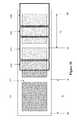
- FIGS. 1 a and 1 bdepict a cross-section view and a plane view, respectively, of a microcup of a color display device of the present invention.
- FIGS. 1 c and 1 ddepict a cross-section view and a plane view, respectively, of an alternative design.
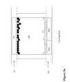
- FIGS. 2 a - 2 dillustrate how different color states may be displayed by a color display of the present invention.
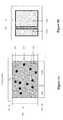
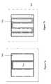
- FIGS. 3 a and 3 bdepict a cross-section view and a plane view, respectively, of an unaligned color display of the present invention.
- FIG. 3 cdepicts a plane view of an alternative un-aligned design.
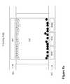
- FIG. 4depicts how different color states may be displayed by an un-aligned color display of the present invention.
- FIGS. 5 a - 5 cdepict an alternative design.
- FIG. 6depicts a further alternative design.
- FIGS. 7 a and 7 bdepict irregular-shaped pixel electrodes.
- FIGS. 8 a - 8 cshow how different colors may be displayed by utilizing the irregular-shaped pixel electrodes of FIG. 7 a.
- FIGS. 9 a - 9 cshow how different colors may be displayed by utilizing the irregular-shaped pixel electrodes of FIG. 7 b.
- FIGS. 10 and 11show un-aligned designs with irregular-shaped pixel electrodes.
- FIGS. 12 a - 12 cillustrate the highlight options.
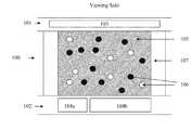
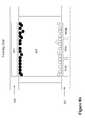
- FIG. 1 adepicts a cross-section view of a color display device of the present invention.
- a microcup ( 100 )is sandwiched between a first layer ( 101 ) and a second layer ( 102 ).
- the microcup ( 100 )is surrounded by partition walls ( 107 ).
- the first layercomprises a common electrode ( 103 ).
- the second layercomprises a pair of pixel electrodes ( 104 a and 104 b ).
- the microcup ( 100 )is a micro-container filled with a display fluid ( 105 ). Details of the term “microcup” are given in U.S. Pat. No. 6,930,818, the content of which is incorporated herein by reference in its entirety.
- microcupsare specifically mentioned in the present application, it is understood that any other micro-containers (e.g., microcapsules or microchannels), regardless of their shapes or sizes, are within the scope of the present application, as long as the micro-containers are filled with a display fluid and have the same functions as the microcups. All such micro-containers may be referred to as “display cells”.
- the display fluid ( 105 )is an electrophoretic fluid comprising two types of pigment particles ( 106 ), black and white carrying charges of opposite polarities.
- the display fluidis colored, e.g., red, green, blue or another color.
- FIG. 1 bdepicts a plane view from the side of the second layer ( 102 ).
- the pair of pixel electrodes ( 104 a and 104 b )together cover substantially the entire display fluid area ( 105 ), but they do not cover any of the partition wall area ( 107 ).
- the pair of pixel electrodes ( 104 a and 104 b )are shown as one larger pixel electrode ( 104 b ) and one smaller pixel electrode ( 104 a ).
- the ratio of the sizes of the two pixel electrodesmay range from 10:1 to 1:1. It is preferred that one pixel electrode is larger than the other (10:1 to 2:1 or 5:1 to 2:1).
- the color displaywould also work if the two pixel electrodes are of substantially the same size.
- the gap between the two pixel electrodesis in the micron range. However the two pixel electrodes cannot be too close to each other as that may cause short circuit. It is also noted that in some of the drawings, the gaps between the two pixel electrodes are exaggerated for clarity.
- the pair of pixel electrodes in FIG. 1 bare shown to have a rectangular shape. It is understood that the shapes of the pixel electrodes may vary, as long as they serve the desired functions.
- FIGS. 1 c and 1 dshow another embodiment in which the two pixel electrodes extend beyond the display fluid area ( 105 ). However the edges of the two pixel electrodes ( 104 a and 104 b ) do not go beyond the midpoint (M) of the partition walls ( 107 ).
- the color displays of FIGS. 1 a - 1 dare referred to as the aligned type as each pair of pixel electrodes are within the boundary of a microcup. More specifically, the two pixel electrodes do not exceed the midpoints of the partition walls surrounding a microcup. An unaligned type is discussed below.
- the common electrode ( 103 )is usually a transparent electrode layer (e.g., ITO), spreading over the entire top of the display device.
- the pixel electrodes ( 104 a and 104 b )are described in U.S. Pat. No. 7,046,228, the content of which is incorporated herein by reference in its entirety.
- first layer ( 101 )is shown in most of drawings as the viewing side, it is also possible for the second layer ( 102 ) to be on the viewing side, which is discussed below.
- colorreferred to in this application may be a single color, a mid-tone color or a composite color.
- the display fluidis of the same color in all microcups. Each pair of the pixel electrodes defines a pixel.
- FIGS. 2 a - 2 dillustrate how different color states may be displayed in this embodiment. For the purpose of illustration, it is assumed that the display fluid is of a red color, the white pigment particles are positively charged and the black particles are negatively charged. The side of the first layer is the viewing side.
- Both the black and white statesutilize the full viewing area of a microcup for reflectivity and therefore provide a non-sacrificed black to white contrast ratio and the maximum reflectance.
- FIG. 2 dis the top view of the second layer ( 202 ) having the white particles at the larger pixel electrode ( 204 b ) and the black particles at the smaller pixel electrode ( 204 a ).
- the light coming from the viewing sidewill be reflected by the white particles and the colored fluid will render the reflected light colored, red, in this case.
- the black particleswill absorb the incoming light and therefore the effective colored reflectance area will be smaller than the area of only the black or white state.
- the display fluidcomprises black and white particles dispersed in a colored solvent, thus causing simultaneous reflection (by the white particles) and absorption (by the black particles) of the color of the display fluid.
- the pair of pixel electrodesdo not have to be aligned with the boundary of a microcup.
- the charged pigment particlesmay still be driven to show the desired color states.
- unalignedor “non-aligned”, in the context of this invention, is intended to mean that at least one of the pixel electrodes in a pair of pixel electrodes is permitted to be underneath more than one microcup.
- the distance (d 1 ) between the midpoints (M) of the two closest partition wallsis substantially the same as the distance (d 2 ) between the midpoints (M′) of one pixel electrode and the next “like” pixel electrode.
- the two like pixel electrodesare 304 b .
- the two like pixel electrodesmay also be 304 a.
- the midpoints M and M′are independent of each other, location wise.
- the distance (d 1 ) between the midpoints (M) of the two closest partition wallsis substantially the same as the distance (d 2 ) between the midpoints (M′) of one pixel electrode and the pixel electrode after the next pixel electrode.
- FIG. 3 bis a plane view from the second layer of FIG. 3 a .
- the microcups and the pixel electrodesare non-aligned in only one direction and in this case, one pixel electrode 304 b is underneath two neighboring microcups.
- FIG. 3 cis a plane view of another example of un-aligned design.
- the microcups ( 300 ) and the pixel electrodesare non-aligned in both directions and in this case, one pixel electrode 304 b is underneath four neighboring microcups.
- the “un-aligned” or “non-aligned” designis not limited to the examples of FIGS. 3 b and 3 c .
- the term “un-aligned” or “non-aligned”would broadly encompass all configurations in which at least one pixel electrode is underneath more than one microcup. In other words, the “un-aligned” or “non-aligned” would also include configurations with microcups and/or pixel electrodes having irregular shapes, sizes or spatial arrangements.
- the width of a microcupdoes not have to be equal to the pitch of the pixel electrode structure.
- FIG. 4depicts a cross-section view of a non-aligned design.
- all of the microcupsare filled with a display fluid of the same color (e.g., red).
- a display fluidof the same color (e.g., red).
- Each pair of the two pixel electrodes ( 404 a and 404 b )defines a pixel.
- the black and white particlesmay move to be near or at the common electrode ( 403 ), the smaller pixel electrodes ( 404 a ) or the large pixel electrodes ( 404 b ).
- the display area corresponding to “A”is seen in the white color state; the display area corresponding to “B” is seen in the black color state; and the display area corresponding to “C” is seen in a red color state.
- FIGS. 5 a - 5 cshow an alternative design of an aligned color display.
- the second layer 502comprising two pixel electrodes 504 a and 504 b is the viewing side.
- the pixel electrodes 504 a and 504 bare transparent.
- the display fluidcomprises black and white particles where the white particles are positively charged and the black particles are negatively charged.
- the display fluidis of a red color.
- FIG. 6is an alternative design of the un-aligned color display device.
- the second layer ( 602 ) comprising pixel electrodesis the viewing side.
- the black and white particlesmay move to be near or at the common electrode ( 603 ), the larger pixel electrodes ( 604 a ) or the smaller pixel electrodes ( 604 b ).
- the display area corresponding to “A′”is seen in the black color state; the display area corresponding to “B′” is seen in the white color state; and the display area corresponding to “C′” is seen in a red color state.
- the two pixel electrodes as shown in FIG. 1 bmay be configured differently in order to increase the speed of image transition.
- FIG. 7 ait is shown that the larger pixel electrode 704 b is in the “U” shape.
- FIG. 7 bit is shown that the larger electrode 704 b is in the “W” shape while the smaller electrode 704 a is in the “U” shape.
- the “U” or “W” shaped pixel electrodeprovides the benefit that the charged pigment particles would travel a shorter distance to the desired location, thus increasing the speed of image transition.
- the term “irregular-shaped”, in the context of the present invention,refers to a pixel electrode of any shape except rectangle or square, which can provide a shorter distance for the charged pigment particles to travel to a desired location.
- the U shaped pixel electrodeis in one piece (i.e., both physically and electrically connected). This also applies to the W shaped pixel electrode shown in FIG. 7 b .
- the term “irregular-shaped” pixel electrodenot only encompasses a pixel electrode which is in one piece (i.e., its elements are both physically and electrically connected), but also encompasses a pixel electrode which is divided into pieces (physically unconnected) but the pieces are electrically connected, as long as the overall shape of the pixel electrode will provide a shorter distance for the charged pigment particles to travel.
- the separate pieces referred tocan be of a rectangle, square or irregular shape.
- the ratio of the total area of the larger irregular-shaped pixel electrode to the total area of the smaller irregular-shaped pixel electrodeis still between the range of 10:1 to 1:1, preferably 10:1 to 2:1. Since the number of pixel electrodes remains to be the same (i.e., two), these new configurations would not increase the complexity of the driving system. In practice, they will cause the image transition to be much faster.
- FIGS. 8 a - 8 cshow how different colors may be displayed utilizing the irregular-shaped pixel electrode design of FIG. 7 a .
- the white and black particlesare dispersed in a red color solvent and the white and black particles carry charges of opposite polarities.
- the white particlesare driven to be at or near the common electrode 803 and the black particles are driven to be at or near the pixel electrode 804 a and the irregular-shaped pixel electrode 804 b (both left and right in the cross-section view), causing the white color to be seen at the top viewing side.
- the white particlesare driven to be at or near the pixel electrode 804 a and the irregular-shaped pixel electrode 804 b (both left and right in the cross-section view) and the black particles are driven to be at or near the common electrode 803 , causing the black color to be seen at the top viewing side.
- the white particlesare driven to be at or near the irregular-shaped pixel electrode 804 b (both left and right in the cross-section view) and the black particles are driven to be near or at the smaller pixel electrode 804 a . Since the total area of the irregular-shaped pixel electrode 804 b is larger than the pixel electrode 804 a , the light reflected by the white particles would be dominant and as a result, the color of the display fluid (i.e., red in this case) is seen at the top viewing side.
- FIGS. 9 a - 9 cshow a display device utilizing the irregular shaped pixel electrode design of FIG. 7 b .
- different color states(white, black and color) may be displayed in a similar manner as those in FIGS. 8 a - 8 c.
- the irregular-shaped pixel electrode configurationsmay be aligned as shown in FIGS. 8 and 9 or un-aligned with a microcup structure, as shown in FIGS. 10 and 11 .
- the display devicemay be viewed from the side of the first layer or the side of the second layer.
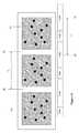
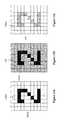
- FIGS. 12 a - 12 cshow highlight options of the present invention.
- FIG. 12 ashows a black image on a white background.
- the black imageis highlighted by the surrounding red color.
- the imageis highlighted by being switched to the red color.
- microcupsare filled with display fluids of different colors.
- the pigment particles in the display fluids of different colorsare still white and black particles of opposite polarities.
- the displaymay display images of multiple colors (e.g., black, white, red, green and blue).
- the two pixel electrodes and the microcupmust be aligned.
- Each pair of the pixel electrodes (or each microcup since they are aligned)is a sub-pixel.
- a full color displaycan be achieved. For example, if the three sub-pixels which make up a pixel are colored red, green and blue, full color images may be obtained by appropriately combining the three colors to make a color pixel.
- the pixel electrodesmust be aligned with the microcups.
- the microcups of the same colori.e., the microcups are filled with a display fluid of the same color
- the pixel electrodes for those microcupsdo not have to be aligned with the microcups in the direction of the row.
- the color displays of the present inventioncan be manufactured by various methods currently available, for example, the methods described in U.S. Pat. No. 6,930,818.
Landscapes
- Physics & Mathematics (AREA)
- Nonlinear Science (AREA)
- General Physics & Mathematics (AREA)
- Optics & Photonics (AREA)
- Health & Medical Sciences (AREA)
- Life Sciences & Earth Sciences (AREA)
- Chemical & Material Sciences (AREA)
- Chemical Kinetics & Catalysis (AREA)
- Electrochemistry (AREA)
- Molecular Biology (AREA)
- Electrochromic Elements, Electrophoresis, Or Variable Reflection Or Absorption Elements (AREA)
Abstract
Description
- a) a plurality of display cells wherein said display cells are filled with a display fluid comprising black and white pigment particles dispersed in a colored solvent wherein the color of the solvent is the same for all of the display cells and the black and white pigment particles carry opposite charge polarities;
- b) a first layer comprising a common electrode; and
- c) a second layer comprising a plurality of pairs of pixel electrodes wherein each pair of pixel electrodes defines a pixel.
- a) a plurality of display cells wherein said display cells are filled with display fluids of different colors, which display fluids of different colors comprise black and white pigment particles dispersed in solvents of different colors and the black and white pigment particles carry opposite charge polarities;
- b) a first layer comprising a common electrode; and
- c) a second layer comprising a plurality of pairs of pixel electrodes wherein each pair of pixel electrodes defines a sub-pixel and is aligned with a display cell.
- a) a row of display cells which display cells are filled with a display fluid comprising black and white pigment particles dispersed in a colored solvent wherein the color of the solvent is the same for said display cells in said row and the black and white pigment particles carry opposite charge polarities;
- b) a first layer comprising a common electrode; and
- c) a second layer comprising a plurality of pairs of pixel electrodes wherein said pixel electrodes are not aligned with said display cells in the direction of said row.
Claims (22)
Priority Applications (1)
| Application Number | Priority Date | Filing Date | Title |
|---|---|---|---|
| US12/547,351US7982941B2 (en) | 2008-09-02 | 2009-08-25 | Color display devices |
Applications Claiming Priority (3)
| Application Number | Priority Date | Filing Date | Title |
|---|---|---|---|
| US9367408P | 2008-09-02 | 2008-09-02 | |
| US14486309P | 2009-01-15 | 2009-01-15 | |
| US12/547,351US7982941B2 (en) | 2008-09-02 | 2009-08-25 | Color display devices |
Publications (2)
| Publication Number | Publication Date |
|---|---|
| US20100053728A1 US20100053728A1 (en) | 2010-03-04 |
| US7982941B2true US7982941B2 (en) | 2011-07-19 |
Family
ID=41725055
Family Applications (1)
| Application Number | Title | Priority Date | Filing Date |
|---|---|---|---|
| US12/547,351Expired - Fee RelatedUS7982941B2 (en) | 2008-09-02 | 2009-08-25 | Color display devices |
Country Status (4)
| Country | Link |
|---|---|
| US (1) | US7982941B2 (en) |
| CN (1) | CN102138094B (en) |
| TW (1) | TWI396030B (en) |
| WO (1) | WO2010027810A1 (en) |
Cited By (82)
| Publication number | Priority date | Publication date | Assignee | Title |
|---|---|---|---|---|
| US20100134538A1 (en)* | 2008-10-24 | 2010-06-03 | Sprague Robert A | Driving methods for electrophoretic displays |
| US20100165448A1 (en)* | 2008-12-30 | 2010-07-01 | Sprague Robert A | Multicolor display architecture using enhanced dark state |
| US20110115774A1 (en)* | 2009-11-13 | 2011-05-19 | Seiko Epson Corporation | Driving method for driving electrophoretic apparatus, electrophoretic display apparatus, electronic device, and controller |
| US20110217639A1 (en)* | 2010-03-02 | 2011-09-08 | Sprague Robert A | Electrophoretic display fluid |
| US20110248909A1 (en)* | 2010-04-12 | 2011-10-13 | Seiko Epson Corporation | Electrophoretic display device and electronic apparatus |
| US8605354B2 (en) | 2011-09-02 | 2013-12-10 | Sipix Imaging, Inc. | Color display devices |
| US8649084B2 (en) | 2011-09-02 | 2014-02-11 | Sipix Imaging, Inc. | Color display devices |
| US8670174B2 (en) | 2010-11-30 | 2014-03-11 | Sipix Imaging, Inc. | Electrophoretic display fluid |
| US8698734B2 (en) | 2010-04-12 | 2014-04-15 | Seiko Epson Corporation | Electrophoretic display device, driving method of the same, and electronic apparatus |
| US8704756B2 (en) | 2010-05-26 | 2014-04-22 | Sipix Imaging, Inc. | Color display architecture and driving methods |
| US8717664B2 (en) | 2012-10-02 | 2014-05-06 | Sipix Imaging, Inc. | Color display device |
| US8786935B2 (en) | 2011-06-02 | 2014-07-22 | Sipix Imaging, Inc. | Color electrophoretic display |
| US8797636B2 (en) | 2012-07-17 | 2014-08-05 | Sipix Imaging, Inc. | Light-enhancing structure for electrophoretic display |
| US8810899B2 (en) | 2008-04-03 | 2014-08-19 | E Ink California, Llc | Color display devices |
| US8917439B2 (en) | 2012-02-09 | 2014-12-23 | E Ink California, Llc | Shutter mode for color display devices |
| US8964282B2 (en) | 2012-10-02 | 2015-02-24 | E Ink California, Llc | Color display device |
| US9013783B2 (en) | 2011-06-02 | 2015-04-21 | E Ink California, Llc | Color electrophoretic display |
| US9116412B2 (en) | 2010-05-26 | 2015-08-25 | E Ink California, Llc | Color display architecture and driving methods |
| US9140952B2 (en) | 2010-04-22 | 2015-09-22 | E Ink California, Llc | Electrophoretic display with enhanced contrast |
| US9146439B2 (en) | 2011-01-31 | 2015-09-29 | E Ink California, Llc | Color electrophoretic display |
| US9170468B2 (en) | 2013-05-17 | 2015-10-27 | E Ink California, Llc | Color display device |
| US9251736B2 (en) | 2009-01-30 | 2016-02-02 | E Ink California, Llc | Multiple voltage level driving for electrophoretic displays |
| US9285649B2 (en) | 2013-04-18 | 2016-03-15 | E Ink California, Llc | Color display device |
| US9360733B2 (en) | 2012-10-02 | 2016-06-07 | E Ink California, Llc | Color display device |
| US9459510B2 (en) | 2013-05-17 | 2016-10-04 | E Ink California, Llc | Color display device with color filters |
| US9513527B2 (en) | 2014-01-14 | 2016-12-06 | E Ink California, Llc | Color display device |
| US9541814B2 (en) | 2014-02-19 | 2017-01-10 | E Ink California, Llc | Color display device |
| US9646547B2 (en) | 2013-05-17 | 2017-05-09 | E Ink California, Llc | Color display device |
| US9759981B2 (en) | 2014-03-18 | 2017-09-12 | E Ink California, Llc | Color display device |
| US9761181B2 (en) | 2014-07-09 | 2017-09-12 | E Ink California, Llc | Color display device |
| US9922603B2 (en) | 2014-07-09 | 2018-03-20 | E Ink California, Llc | Color display device and driving methods therefor |
| US10062337B2 (en) | 2015-10-12 | 2018-08-28 | E Ink California, Llc | Electrophoretic display device |
| WO2018164942A1 (en) | 2017-03-06 | 2018-09-13 | E Ink Corporation | Method for rendering color images |
| US10147366B2 (en) | 2014-11-17 | 2018-12-04 | E Ink California, Llc | Methods for driving four particle electrophoretic display |
| US10162242B2 (en) | 2013-10-11 | 2018-12-25 | E Ink California, Llc | Color display device |
| US10254619B2 (en) | 2013-05-17 | 2019-04-09 | E Ink California, Llc | Driving methods for color display devices |
| US10270939B2 (en) | 2016-05-24 | 2019-04-23 | E Ink Corporation | Method for rendering color images |
| US10276109B2 (en) | 2016-03-09 | 2019-04-30 | E Ink Corporation | Method for driving electro-optic displays |
| US10380955B2 (en) | 2014-07-09 | 2019-08-13 | E Ink California, Llc | Color display device and driving methods therefor |
| US10514583B2 (en) | 2011-01-31 | 2019-12-24 | E Ink California, Llc | Color electrophoretic display |
| US10593272B2 (en) | 2016-03-09 | 2020-03-17 | E Ink Corporation | Drivers providing DC-balanced refresh sequences for color electrophoretic displays |
| US10782586B2 (en) | 2017-01-20 | 2020-09-22 | E Ink California, Llc | Color organic pigments and electrophoretic display media containing the same |
| US10891906B2 (en) | 2014-07-09 | 2021-01-12 | E Ink California, Llc | Color display device and driving methods therefor |
| US11017705B2 (en) | 2012-10-02 | 2021-05-25 | E Ink California, Llc | Color display device including multiple pixels for driving three-particle electrophoretic media |
| US11079651B2 (en) | 2017-12-15 | 2021-08-03 | E Ink Corporation | Multi-color electro-optic media |
| US11087644B2 (en) | 2015-08-19 | 2021-08-10 | E Ink Corporation | Displays intended for use in architectural applications |
| US11143929B2 (en) | 2018-03-09 | 2021-10-12 | E Ink Corporation | Reflective electrophoretic displays including photo-luminescent material and color filter arrays |
| WO2021247991A1 (en) | 2020-06-05 | 2021-12-09 | E Ink California, Llc | Electrophoretic display device |
| US11248122B2 (en) | 2017-12-30 | 2022-02-15 | E Ink Corporation | Pigments for electrophoretic displays |
| US11266832B2 (en) | 2017-11-14 | 2022-03-08 | E Ink California, Llc | Electrophoretic active delivery system including porous conductive electrode layer |
| US11422427B2 (en) | 2017-12-19 | 2022-08-23 | E Ink Corporation | Applications of electro-optic displays |
| WO2023043714A1 (en) | 2021-09-14 | 2023-03-23 | E Ink Corporation | Coordinated top electrode - drive electrode voltages for switching optical state of electrophoretic displays using positive and negative voltages of different magnitudes |
| US11620959B2 (en) | 2020-11-02 | 2023-04-04 | E Ink Corporation | Enhanced push-pull (EPP) waveforms for achieving primary color sets in multi-color electrophoretic displays |
| US11640803B2 (en) | 2021-09-06 | 2023-05-02 | E Ink California, Llc | Method for driving electrophoretic display device |
| US11686989B2 (en) | 2020-09-15 | 2023-06-27 | E Ink Corporation | Four particle electrophoretic medium providing fast, high-contrast optical state switching |
| WO2023132958A1 (en) | 2022-01-04 | 2023-07-13 | E Ink Corporation | Electrophoretic media comprising electrophoretic particles and a combination of charge control agents |
| US11721296B2 (en) | 2020-11-02 | 2023-08-08 | E Ink Corporation | Method and apparatus for rendering color images |
| US11756494B2 (en) | 2020-11-02 | 2023-09-12 | E Ink Corporation | Driving sequences to remove prior state information from color electrophoretic displays |
| US11776496B2 (en) | 2020-09-15 | 2023-10-03 | E Ink Corporation | Driving voltages for advanced color electrophoretic displays and displays with improved driving voltages |
| WO2023211867A1 (en) | 2022-04-27 | 2023-11-02 | E Ink Corporation | Color displays configured to convert rgb image data for display on advanced color electronic paper |
| US11846863B2 (en) | 2020-09-15 | 2023-12-19 | E Ink Corporation | Coordinated top electrode—drive electrode voltages for switching optical state of electrophoretic displays using positive and negative voltages of different magnitudes |
| US11869451B2 (en) | 2021-11-05 | 2024-01-09 | E Ink Corporation | Multi-primary display mask-based dithering with low blooming sensitivity |
| WO2024044119A1 (en) | 2022-08-25 | 2024-02-29 | E Ink Corporation | Transitional driving modes for impulse balancing when switching between global color mode and direct update mode for electrophoretic displays |
| US11922893B2 (en) | 2021-12-22 | 2024-03-05 | E Ink Corporation | High voltage driving using top plane switching with zero voltage frames between driving frames |
| US11938215B2 (en) | 2019-11-27 | 2024-03-26 | E Ink Corporation | Method for operating a benefit agent delivery system comprising microcells having an electrically eroding sealing layer |
| US12125449B2 (en) | 2021-02-09 | 2024-10-22 | E Ink Corporation | Continuous waveform driving in multi-color electrophoretic displays |
| WO2024253934A1 (en) | 2023-06-05 | 2024-12-12 | E Ink Corporation | Color electrophoretic medium having four pigment particle system addressable by waveforms having four voltage levels |
| US12181767B2 (en) | 2020-09-15 | 2024-12-31 | E Ink Corporation | Five-particle electrophoretic medium with improved black optical state |
| WO2025006440A1 (en) | 2023-06-27 | 2025-01-02 | E Ink Corporation | Time-shifted waveforms for multi-particle electrophoretic displays providing low-flash image updates |
| WO2025006476A1 (en) | 2023-06-27 | 2025-01-02 | E Ink Corporation | Multi-particle electrophoretic display having low-flash image updates |
| WO2025006130A1 (en) | 2023-06-27 | 2025-01-02 | E Ink Corporation | Electrophoretic device with ambient light sensor and adaptive whiteness restoring and color balancing frontlight |
| WO2025034396A1 (en) | 2023-08-08 | 2025-02-13 | E Ink Corporation | Backplanes for segmented electro-optic displays and methods of manufacturing same |
| WO2025076061A1 (en) | 2023-10-05 | 2025-04-10 | E Ink Corporation | Staged gate voltage control |
| WO2025096100A1 (en) | 2023-10-31 | 2025-05-08 | E Ink Corporation | Reflective display and projected capacitive touch sensor with shared transparent electrode |
| WO2025128843A1 (en) | 2023-12-15 | 2025-06-19 | E Ink Corporation | Fast response color waveforms for multiparticle electrophoretic displays |
| WO2025136446A1 (en) | 2023-12-22 | 2025-06-26 | E Ink Corporation | Five-particle electrophoretic medium with improved black optical state |
| WO2025147410A2 (en) | 2024-01-02 | 2025-07-10 | E Ink Corporation | Electrophoretic media comprising a cationic charge control agent |
| WO2025147504A1 (en) | 2024-01-05 | 2025-07-10 | E Ink Corporation | An electrophoretic medium comprising particles having a pigment core and a polymeric shell |
| WO2025151355A1 (en) | 2024-01-08 | 2025-07-17 | E Ink Corporation | Electrophoretic device having an adhesive layer comprising conductive filler particles and a polymeric dispersant |
| WO2025155697A1 (en) | 2024-01-20 | 2025-07-24 | E Ink Corporation | Methods for delivering low-ghosting partial updates in color electrophoretic displays |
| WO2025155412A1 (en) | 2024-01-19 | 2025-07-24 | E Ink Corporation | Flexible segmented electro-optic displays and methods of manufacture |
| WO2025160290A1 (en) | 2024-01-24 | 2025-07-31 | E Ink Corporation | Improved methods for producing full-color epaper images with low grain |
Families Citing this family (10)
| Publication number | Priority date | Publication date | Assignee | Title |
|---|---|---|---|---|
| US8169690B2 (en) | 2008-02-21 | 2012-05-01 | Sipix Imaging, Inc. | Color display devices |
| WO2009134889A1 (en)* | 2008-05-01 | 2009-11-05 | Sipix Imaging, Inc. | Color display devices |
| US8797258B2 (en)* | 2008-12-30 | 2014-08-05 | Sipix Imaging, Inc. | Highlight color display architecture using enhanced dark state |
| TWI455088B (en)* | 2010-07-08 | 2014-10-01 | Sipix Imaging Inc | Three dimensional driving scheme for electrophoretic display devices |
| CN104411776B (en)* | 2012-06-22 | 2017-08-18 | 默克专利有限公司 | Electrophoretic fluid |
| WO2014019650A1 (en) | 2012-08-01 | 2014-02-06 | Merck Patent Gmbh | Electrophoretic fluids |
| EP3083834B1 (en) | 2013-12-19 | 2018-05-30 | Merck Patent GmbH | Electrophoretic fluid |
| US9568727B2 (en)* | 2014-03-25 | 2017-02-14 | Amazon Technologies, Inc. | Electrowetting display pixel architecture |
| CN106909011B (en)* | 2017-05-10 | 2020-06-05 | 上海天马微电子有限公司 | Electronic paper display panel, driving method and electronic paper display device |
| CN110133938A (en)* | 2019-05-30 | 2019-08-16 | 京东方科技集团股份有限公司 | Display panel, driving method thereof, and display device |
Citations (8)
| Publication number | Priority date | Publication date | Assignee | Title |
|---|---|---|---|---|
| WO2001067170A1 (en) | 2000-03-03 | 2001-09-13 | Sipix Imaging, Inc. | Electrophoretic display |
| US7046228B2 (en) | 2001-08-17 | 2006-05-16 | Sipix Imaging, Inc. | Electrophoretic display with dual mode switching |
| US7283119B2 (en) | 2002-06-14 | 2007-10-16 | Canon Kabushiki Kaisha | Color electrophoretic display device |
| US7365732B2 (en) | 2002-05-13 | 2008-04-29 | Canon Kabushiki Kaisha | Display device employing electrophoretic migration |
| US7417787B2 (en) | 2006-05-19 | 2008-08-26 | Xerox Corporation | Electrophoretic display device |
| WO2009105385A1 (en) | 2008-02-21 | 2009-08-27 | Sipix Imaging, Inc. | Color display devices |
| US20100165448A1 (en)* | 2008-12-30 | 2010-07-01 | Sprague Robert A | Multicolor display architecture using enhanced dark state |
| US20100165005A1 (en)* | 2008-12-30 | 2010-07-01 | Sprague Robert A | Highlight color display architecture using enhanced dark state |
Family Cites Families (3)
| Publication number | Priority date | Publication date | Assignee | Title |
|---|---|---|---|---|
| US7075502B1 (en)* | 1998-04-10 | 2006-07-11 | E Ink Corporation | Full color reflective display with multichromatic sub-pixels |
| TWI320508B (en)* | 2004-12-17 | 2010-02-11 | Sipix Imaging Inc | Backplane design for display panels and processes for their manufacture |
| JP4862311B2 (en)* | 2005-07-25 | 2012-01-25 | 富士ゼロックス株式会社 | Image display device |
- 2009
- 2009-08-25CNCN200980134972.7Apatent/CN102138094B/enactiveActive
- 2009-08-25USUS12/547,351patent/US7982941B2/ennot_activeExpired - Fee Related
- 2009-08-25WOPCT/US2009/054939patent/WO2010027810A1/enactiveApplication Filing
- 2009-08-27TWTW098128768Apatent/TWI396030B/ennot_activeIP Right Cessation
Patent Citations (10)
| Publication number | Priority date | Publication date | Assignee | Title |
|---|---|---|---|---|
| WO2001067170A1 (en) | 2000-03-03 | 2001-09-13 | Sipix Imaging, Inc. | Electrophoretic display |
| US6930818B1 (en) | 2000-03-03 | 2005-08-16 | Sipix Imaging, Inc. | Electrophoretic display and novel process for its manufacture |
| US7046228B2 (en) | 2001-08-17 | 2006-05-16 | Sipix Imaging, Inc. | Electrophoretic display with dual mode switching |
| US7365732B2 (en) | 2002-05-13 | 2008-04-29 | Canon Kabushiki Kaisha | Display device employing electrophoretic migration |
| US7283119B2 (en) | 2002-06-14 | 2007-10-16 | Canon Kabushiki Kaisha | Color electrophoretic display device |
| US7417787B2 (en) | 2006-05-19 | 2008-08-26 | Xerox Corporation | Electrophoretic display device |
| WO2009105385A1 (en) | 2008-02-21 | 2009-08-27 | Sipix Imaging, Inc. | Color display devices |
| US20090213452A1 (en) | 2008-02-21 | 2009-08-27 | Craig Lin | Color display devices |
| US20100165448A1 (en)* | 2008-12-30 | 2010-07-01 | Sprague Robert A | Multicolor display architecture using enhanced dark state |
| US20100165005A1 (en)* | 2008-12-30 | 2010-07-01 | Sprague Robert A | Highlight color display architecture using enhanced dark state |
Non-Patent Citations (1)
| Title |
|---|
| International Search Report for PCT/US09/54939, mailed Oct. 20, 2009. |
Cited By (129)
| Publication number | Priority date | Publication date | Assignee | Title |
|---|---|---|---|---|
| US8810899B2 (en) | 2008-04-03 | 2014-08-19 | E Ink California, Llc | Color display devices |
| US20100134538A1 (en)* | 2008-10-24 | 2010-06-03 | Sprague Robert A | Driving methods for electrophoretic displays |
| US8558855B2 (en)* | 2008-10-24 | 2013-10-15 | Sipix Imaging, Inc. | Driving methods for electrophoretic displays |
| US8503063B2 (en) | 2008-12-30 | 2013-08-06 | Sipix Imaging, Inc. | Multicolor display architecture using enhanced dark state |
| US20100165448A1 (en)* | 2008-12-30 | 2010-07-01 | Sprague Robert A | Multicolor display architecture using enhanced dark state |
| US9251736B2 (en) | 2009-01-30 | 2016-02-02 | E Ink California, Llc | Multiple voltage level driving for electrophoretic displays |
| US20110115774A1 (en)* | 2009-11-13 | 2011-05-19 | Seiko Epson Corporation | Driving method for driving electrophoretic apparatus, electrophoretic display apparatus, electronic device, and controller |
| US20110217639A1 (en)* | 2010-03-02 | 2011-09-08 | Sprague Robert A | Electrophoretic display fluid |
| US20110248909A1 (en)* | 2010-04-12 | 2011-10-13 | Seiko Epson Corporation | Electrophoretic display device and electronic apparatus |
| US8698734B2 (en) | 2010-04-12 | 2014-04-15 | Seiko Epson Corporation | Electrophoretic display device, driving method of the same, and electronic apparatus |
| US9140952B2 (en) | 2010-04-22 | 2015-09-22 | E Ink California, Llc | Electrophoretic display with enhanced contrast |
| US8704756B2 (en) | 2010-05-26 | 2014-04-22 | Sipix Imaging, Inc. | Color display architecture and driving methods |
| US9116412B2 (en) | 2010-05-26 | 2015-08-25 | E Ink California, Llc | Color display architecture and driving methods |
| US8670174B2 (en) | 2010-11-30 | 2014-03-11 | Sipix Imaging, Inc. | Electrophoretic display fluid |
| US10514583B2 (en) | 2011-01-31 | 2019-12-24 | E Ink California, Llc | Color electrophoretic display |
| US9146439B2 (en) | 2011-01-31 | 2015-09-29 | E Ink California, Llc | Color electrophoretic display |
| US9013783B2 (en) | 2011-06-02 | 2015-04-21 | E Ink California, Llc | Color electrophoretic display |
| US8786935B2 (en) | 2011-06-02 | 2014-07-22 | Sipix Imaging, Inc. | Color electrophoretic display |
| US8976444B2 (en) | 2011-09-02 | 2015-03-10 | E Ink California, Llc | Color display devices |
| US8605354B2 (en) | 2011-09-02 | 2013-12-10 | Sipix Imaging, Inc. | Color display devices |
| US8649084B2 (en) | 2011-09-02 | 2014-02-11 | Sipix Imaging, Inc. | Color display devices |
| US8917439B2 (en) | 2012-02-09 | 2014-12-23 | E Ink California, Llc | Shutter mode for color display devices |
| US8797636B2 (en) | 2012-07-17 | 2014-08-05 | Sipix Imaging, Inc. | Light-enhancing structure for electrophoretic display |
| US8964282B2 (en) | 2012-10-02 | 2015-02-24 | E Ink California, Llc | Color display device |
| US11017705B2 (en) | 2012-10-02 | 2021-05-25 | E Ink California, Llc | Color display device including multiple pixels for driving three-particle electrophoretic media |
| US8717664B2 (en) | 2012-10-02 | 2014-05-06 | Sipix Imaging, Inc. | Color display device |
| US9360733B2 (en) | 2012-10-02 | 2016-06-07 | E Ink California, Llc | Color display device |
| US9285649B2 (en) | 2013-04-18 | 2016-03-15 | E Ink California, Llc | Color display device |
| US10254619B2 (en) | 2013-05-17 | 2019-04-09 | E Ink California, Llc | Driving methods for color display devices |
| US9646547B2 (en) | 2013-05-17 | 2017-05-09 | E Ink California, Llc | Color display device |
| US9459510B2 (en) | 2013-05-17 | 2016-10-04 | E Ink California, Llc | Color display device with color filters |
| US10901287B2 (en) | 2013-05-17 | 2021-01-26 | E Ink California, Llc | Driving methods for color display devices |
| US9170468B2 (en) | 2013-05-17 | 2015-10-27 | E Ink California, Llc | Color display device |
| US10162242B2 (en) | 2013-10-11 | 2018-12-25 | E Ink California, Llc | Color display device |
| US10036931B2 (en) | 2014-01-14 | 2018-07-31 | E Ink California, Llc | Color display device |
| US10234742B2 (en) | 2014-01-14 | 2019-03-19 | E Ink California, Llc | Color display device |
| US9513527B2 (en) | 2014-01-14 | 2016-12-06 | E Ink California, Llc | Color display device |
| US9541814B2 (en) | 2014-02-19 | 2017-01-10 | E Ink California, Llc | Color display device |
| US9759981B2 (en) | 2014-03-18 | 2017-09-12 | E Ink California, Llc | Color display device |
| US9761181B2 (en) | 2014-07-09 | 2017-09-12 | E Ink California, Llc | Color display device |
| US11315505B2 (en) | 2014-07-09 | 2022-04-26 | E Ink California, Llc | Color display device and driving methods therefor |
| US10380955B2 (en) | 2014-07-09 | 2019-08-13 | E Ink California, Llc | Color display device and driving methods therefor |
| US9922603B2 (en) | 2014-07-09 | 2018-03-20 | E Ink California, Llc | Color display device and driving methods therefor |
| US10891906B2 (en) | 2014-07-09 | 2021-01-12 | E Ink California, Llc | Color display device and driving methods therefor |
| US10586499B2 (en) | 2014-11-17 | 2020-03-10 | E Ink California, Llc | Electrophoretic display including four particles with different charges and optical characteristics |
| US10147366B2 (en) | 2014-11-17 | 2018-12-04 | E Ink California, Llc | Methods for driving four particle electrophoretic display |
| US10431168B2 (en) | 2014-11-17 | 2019-10-01 | E Ink California, Llc | Methods for driving four particle electrophoretic display |
| US10891907B2 (en) | 2014-11-17 | 2021-01-12 | E Ink California, Llc | Electrophoretic display including four particles with different charges and optical characteristics |
| US11087644B2 (en) | 2015-08-19 | 2021-08-10 | E Ink Corporation | Displays intended for use in architectural applications |
| US10062337B2 (en) | 2015-10-12 | 2018-08-28 | E Ink California, Llc | Electrophoretic display device |
| US11030965B2 (en) | 2016-03-09 | 2021-06-08 | E Ink Corporation | Drivers providing DC-balanced refresh sequences for color electrophoretic displays |
| US10593272B2 (en) | 2016-03-09 | 2020-03-17 | E Ink Corporation | Drivers providing DC-balanced refresh sequences for color electrophoretic displays |
| US10276109B2 (en) | 2016-03-09 | 2019-04-30 | E Ink Corporation | Method for driving electro-optic displays |
| US11404012B2 (en) | 2016-03-09 | 2022-08-02 | E Ink Corporation | Drivers providing DC-balanced refresh sequences for color electrophoretic displays |
| US10771652B2 (en) | 2016-05-24 | 2020-09-08 | E Ink Corporation | Method for rendering color images |
| US10554854B2 (en) | 2016-05-24 | 2020-02-04 | E Ink Corporation | Method for rendering color images |
| US10270939B2 (en) | 2016-05-24 | 2019-04-23 | E Ink Corporation | Method for rendering color images |
| US11265443B2 (en) | 2016-05-24 | 2022-03-01 | E Ink Corporation | System for rendering color images |
| US11493820B2 (en) | 2017-01-20 | 2022-11-08 | E Ink California, Llc | Color organic pigments and electrophoretic display media containing the same |
| US10782586B2 (en) | 2017-01-20 | 2020-09-22 | E Ink California, Llc | Color organic pigments and electrophoretic display media containing the same |
| US11099452B2 (en) | 2017-01-20 | 2021-08-24 | E Ink California, Llc | Color organic pigments and electrophoretic display media containing the same |
| US12100369B2 (en) | 2017-03-06 | 2024-09-24 | E Ink Corporation | Method for rendering color images |
| US11527216B2 (en) | 2017-03-06 | 2022-12-13 | E Ink Corporation | Method for rendering color images |
| US11094288B2 (en) | 2017-03-06 | 2021-08-17 | E Ink Corporation | Method and apparatus for rendering color images |
| US10467984B2 (en) | 2017-03-06 | 2019-11-05 | E Ink Corporation | Method for rendering color images |
| WO2018164942A1 (en) | 2017-03-06 | 2018-09-13 | E Ink Corporation | Method for rendering color images |
| US11266832B2 (en) | 2017-11-14 | 2022-03-08 | E Ink California, Llc | Electrophoretic active delivery system including porous conductive electrode layer |
| US11079651B2 (en) | 2017-12-15 | 2021-08-03 | E Ink Corporation | Multi-color electro-optic media |
| US11422427B2 (en) | 2017-12-19 | 2022-08-23 | E Ink Corporation | Applications of electro-optic displays |
| US12130530B2 (en) | 2017-12-19 | 2024-10-29 | E Ink Corporation | Applications of electro-optic displays |
| US11248122B2 (en) | 2017-12-30 | 2022-02-15 | E Ink Corporation | Pigments for electrophoretic displays |
| US11613654B2 (en) | 2017-12-30 | 2023-03-28 | E Ink Corporation | Pigments for electrophoretic displays |
| US11143929B2 (en) | 2018-03-09 | 2021-10-12 | E Ink Corporation | Reflective electrophoretic displays including photo-luminescent material and color filter arrays |
| US11656523B2 (en) | 2018-03-09 | 2023-05-23 | E Ink Corporation | Reflective electrophoretic displays including photo-luminescent material and color filter arrays |
| US11938214B2 (en) | 2019-11-27 | 2024-03-26 | E Ink Corporation | Benefit agent delivery system comprising microcells having an electrically eroding sealing layer |
| US11938215B2 (en) | 2019-11-27 | 2024-03-26 | E Ink Corporation | Method for operating a benefit agent delivery system comprising microcells having an electrically eroding sealing layer |
| WO2021247991A1 (en) | 2020-06-05 | 2021-12-09 | E Ink California, Llc | Electrophoretic display device |
| US12360429B2 (en) | 2020-06-05 | 2025-07-15 | E Ink Corporation | Electrophoretic display device |
| US11868020B2 (en) | 2020-06-05 | 2024-01-09 | E Ink Corporation | Electrophoretic display device |
| US12197099B2 (en) | 2020-09-15 | 2025-01-14 | E Ink Corporation | Coordinated top electrode—drive electrode voltages for switching optical state of electrophoretic displays using positive and negative voltages of different magnitudes |
| US11948523B1 (en) | 2020-09-15 | 2024-04-02 | E Ink Corporation | Driving voltages for advanced color electrophoretic displays and displays with improved driving voltages |
| US12044945B2 (en) | 2020-09-15 | 2024-07-23 | E Ink Corporation | Four particle electrophoretic medium providing fast, high-contrast optical state switching |
| US11776496B2 (en) | 2020-09-15 | 2023-10-03 | E Ink Corporation | Driving voltages for advanced color electrophoretic displays and displays with improved driving voltages |
| US11686989B2 (en) | 2020-09-15 | 2023-06-27 | E Ink Corporation | Four particle electrophoretic medium providing fast, high-contrast optical state switching |
| US11837184B2 (en) | 2020-09-15 | 2023-12-05 | E Ink Corporation | Driving voltages for advanced color electrophoretic displays and displays with improved driving voltages |
| US11846863B2 (en) | 2020-09-15 | 2023-12-19 | E Ink Corporation | Coordinated top electrode—drive electrode voltages for switching optical state of electrophoretic displays using positive and negative voltages of different magnitudes |
| US12361902B2 (en) | 2020-09-15 | 2025-07-15 | E Ink Corporation | Driving voltages for advanced color electrophoretic displays and displays with improved driving voltages |
| US12181767B2 (en) | 2020-09-15 | 2024-12-31 | E Ink Corporation | Five-particle electrophoretic medium with improved black optical state |
| US12307989B2 (en) | 2020-11-02 | 2025-05-20 | E Ink Corporation | Driving sequences to remove prior state information from color electrophoretic displays |
| US11721296B2 (en) | 2020-11-02 | 2023-08-08 | E Ink Corporation | Method and apparatus for rendering color images |
| US12347398B2 (en) | 2020-11-02 | 2025-07-01 | E Ink Corporation | Enhanced push-pull (EPP) waveforms for achieving primary color sets in multi-color electrophoretic displays |
| US11756494B2 (en) | 2020-11-02 | 2023-09-12 | E Ink Corporation | Driving sequences to remove prior state information from color electrophoretic displays |
| US11620959B2 (en) | 2020-11-02 | 2023-04-04 | E Ink Corporation | Enhanced push-pull (EPP) waveforms for achieving primary color sets in multi-color electrophoretic displays |
| US11798506B2 (en) | 2020-11-02 | 2023-10-24 | E Ink Corporation | Enhanced push-pull (EPP) waveforms for achieving primary color sets in multi-color electrophoretic displays |
| US12087244B2 (en) | 2020-11-02 | 2024-09-10 | E Ink Corporation | Enhanced push-pull (EPP) waveforms for achieving primary color sets in multi-color electrophoretic displays |
| US12125449B2 (en) | 2021-02-09 | 2024-10-22 | E Ink Corporation | Continuous waveform driving in multi-color electrophoretic displays |
| US12131713B2 (en) | 2021-02-09 | 2024-10-29 | E Ink Corporation | Continuous waveform driving in multi-color electrophoretic displays |
| US12406632B2 (en) | 2021-02-09 | 2025-09-02 | E Ink Corporation | Continuous waveform driving in multi-color electrophoretic displays |
| US11804190B2 (en) | 2021-09-06 | 2023-10-31 | E Ink California, Llc | Method for driving electrophoretic display device |
| US11640803B2 (en) | 2021-09-06 | 2023-05-02 | E Ink California, Llc | Method for driving electrophoretic display device |
| US12094429B2 (en) | 2021-09-06 | 2024-09-17 | E Ink Corporation | Method for driving electrophoretic display device |
| WO2023043714A1 (en) | 2021-09-14 | 2023-03-23 | E Ink Corporation | Coordinated top electrode - drive electrode voltages for switching optical state of electrophoretic displays using positive and negative voltages of different magnitudes |
| US11869451B2 (en) | 2021-11-05 | 2024-01-09 | E Ink Corporation | Multi-primary display mask-based dithering with low blooming sensitivity |
| US12249291B2 (en) | 2021-11-05 | 2025-03-11 | E Ink Corporation | Multi-primary display mask-based dithering with low blooming sensitivity |
| US11922893B2 (en) | 2021-12-22 | 2024-03-05 | E Ink Corporation | High voltage driving using top plane switching with zero voltage frames between driving frames |
| US12400611B2 (en) | 2021-12-22 | 2025-08-26 | E Ink Corporation | High voltage driving using top plane switching with zero voltage frames between driving frames |
| WO2023132958A1 (en) | 2022-01-04 | 2023-07-13 | E Ink Corporation | Electrophoretic media comprising electrophoretic particles and a combination of charge control agents |
| US12334029B2 (en) | 2022-04-27 | 2025-06-17 | E Ink Corporation | Color displays configured to convert RGB image data for display on advanced color electronic paper |
| WO2023211867A1 (en) | 2022-04-27 | 2023-11-02 | E Ink Corporation | Color displays configured to convert rgb image data for display on advanced color electronic paper |
| US11984088B2 (en) | 2022-04-27 | 2024-05-14 | E Ink Corporation | Color displays configured to convert RGB image data for display on advanced color electronic paper |
| WO2024044119A1 (en) | 2022-08-25 | 2024-02-29 | E Ink Corporation | Transitional driving modes for impulse balancing when switching between global color mode and direct update mode for electrophoretic displays |
| WO2024253934A1 (en) | 2023-06-05 | 2024-12-12 | E Ink Corporation | Color electrophoretic medium having four pigment particle system addressable by waveforms having four voltage levels |
| US12412538B2 (en) | 2023-06-27 | 2025-09-09 | E Ink Corporation | Electrophoretic device with ambient light sensor and adaptive whiteness restoring and color balancing frontlight |
| US12394388B2 (en) | 2023-06-27 | 2025-08-19 | E Ink Corporation | Time-shifted waveforms for multi-particle electrophoretic displays providing low-flash image updates |
| US12406631B2 (en) | 2023-06-27 | 2025-09-02 | E Ink Corporation | Multi-particle electrophoretic display having low-flash image updates |
| WO2025006130A1 (en) | 2023-06-27 | 2025-01-02 | E Ink Corporation | Electrophoretic device with ambient light sensor and adaptive whiteness restoring and color balancing frontlight |
| WO2025006476A1 (en) | 2023-06-27 | 2025-01-02 | E Ink Corporation | Multi-particle electrophoretic display having low-flash image updates |
| WO2025006440A1 (en) | 2023-06-27 | 2025-01-02 | E Ink Corporation | Time-shifted waveforms for multi-particle electrophoretic displays providing low-flash image updates |
| WO2025034396A1 (en) | 2023-08-08 | 2025-02-13 | E Ink Corporation | Backplanes for segmented electro-optic displays and methods of manufacturing same |
| WO2025076061A1 (en) | 2023-10-05 | 2025-04-10 | E Ink Corporation | Staged gate voltage control |
| WO2025096100A1 (en) | 2023-10-31 | 2025-05-08 | E Ink Corporation | Reflective display and projected capacitive touch sensor with shared transparent electrode |
| WO2025128843A1 (en) | 2023-12-15 | 2025-06-19 | E Ink Corporation | Fast response color waveforms for multiparticle electrophoretic displays |
| WO2025136446A1 (en) | 2023-12-22 | 2025-06-26 | E Ink Corporation | Five-particle electrophoretic medium with improved black optical state |
| WO2025147410A2 (en) | 2024-01-02 | 2025-07-10 | E Ink Corporation | Electrophoretic media comprising a cationic charge control agent |
| WO2025147504A1 (en) | 2024-01-05 | 2025-07-10 | E Ink Corporation | An electrophoretic medium comprising particles having a pigment core and a polymeric shell |
| WO2025151355A1 (en) | 2024-01-08 | 2025-07-17 | E Ink Corporation | Electrophoretic device having an adhesive layer comprising conductive filler particles and a polymeric dispersant |
| WO2025155412A1 (en) | 2024-01-19 | 2025-07-24 | E Ink Corporation | Flexible segmented electro-optic displays and methods of manufacture |
| WO2025155697A1 (en) | 2024-01-20 | 2025-07-24 | E Ink Corporation | Methods for delivering low-ghosting partial updates in color electrophoretic displays |
| WO2025160290A1 (en) | 2024-01-24 | 2025-07-31 | E Ink Corporation | Improved methods for producing full-color epaper images with low grain |
Also Published As
| Publication number | Publication date |
|---|---|
| TWI396030B (en) | 2013-05-11 |
| US20100053728A1 (en) | 2010-03-04 |
| WO2010027810A1 (en) | 2010-03-11 |
| CN102138094B (en) | 2015-07-29 |
| CN102138094A (en) | 2011-07-27 |
| TW201013290A (en) | 2010-04-01 |
Similar Documents
| Publication | Publication Date | Title |
|---|---|---|
| US7982941B2 (en) | Color display devices | |
| US8797258B2 (en) | Highlight color display architecture using enhanced dark state | |
| US8976444B2 (en) | Color display devices | |
| US8649084B2 (en) | Color display devices | |
| US8917439B2 (en) | Shutter mode for color display devices | |
| TWI446321B (en) | Color display architecture and driving methods | |
| US9140952B2 (en) | Electrophoretic display with enhanced contrast | |
| US8503063B2 (en) | Multicolor display architecture using enhanced dark state | |
| US7808696B2 (en) | Electrophoretic display device and fabrication thereof | |
| US8077374B2 (en) | Display devices using electrochromism and polymer dispersed liquid crystal and methods of driving the same | |
| US20100060628A1 (en) | In-plane switching electrophoretic colour display | |
| US9291872B1 (en) | Electrophoretic display design | |
| US20100103501A1 (en) | Electrophoretic display structures | |
| KR100888479B1 (en) | Surface plasmon display element | |
| WO2019161642A1 (en) | Color display device | |
| CN115903327A (en) | Electronic paper and its driving method | |
| KR101258466B1 (en) | Multi color electrophoretic display device and method of driving the device | |
| US8730561B2 (en) | Electrophoretic display device and driving method thereof | |
| KR101267646B1 (en) | color display device | |
| CN105573005A (en) | Electrophoresis display device and drive method thereof | |
| CN105093771A (en) | Subpixel structure, pixel structure, display panel and display device | |
| US20110095972A1 (en) | Electrophoretic display device |
Legal Events
| Date | Code | Title | Description |
|---|---|---|---|
| AS | Assignment | Owner name:SIPIX IMAGING, INC.,CALIFORNIA Free format text:ASSIGNMENT OF ASSIGNORS INTEREST;ASSIGNORS:LIN, CRAIG;SPRAGUE, ROBERT A.;REEL/FRAME:023398/0608 Effective date:20091007 Owner name:SIPIX IMAGING, INC., CALIFORNIA Free format text:ASSIGNMENT OF ASSIGNORS INTEREST;ASSIGNORS:LIN, CRAIG;SPRAGUE, ROBERT A.;REEL/FRAME:023398/0608 Effective date:20091007 | |
| STCF | Information on status: patent grant | Free format text:PATENTED CASE | |
| AS | Assignment | Owner name:E INK CALIFORNIA, LLC, CALIFORNIA Free format text:CHANGE OF NAME;ASSIGNOR:SIPIX IMAGING, INC.;REEL/FRAME:033280/0408 Effective date:20140701 | |
| FPAY | Fee payment | Year of fee payment:4 | |
| FEPP | Fee payment procedure | Free format text:MAINTENANCE FEE REMINDER MAILED (ORIGINAL EVENT CODE: REM.); ENTITY STATUS OF PATENT OWNER: LARGE ENTITY | |
| LAPS | Lapse for failure to pay maintenance fees | Free format text:PATENT EXPIRED FOR FAILURE TO PAY MAINTENANCE FEES (ORIGINAL EVENT CODE: EXP.); ENTITY STATUS OF PATENT OWNER: LARGE ENTITY | |
| STCH | Information on status: patent discontinuation | Free format text:PATENT EXPIRED DUE TO NONPAYMENT OF MAINTENANCE FEES UNDER 37 CFR 1.362 | |
| FP | Lapsed due to failure to pay maintenance fee | Effective date:20190719 |