US7981451B2 - Capsule for the preparation of a beverage - Google Patents
Capsule for the preparation of a beverageDownload PDFInfo
- Publication number
- US7981451B2 US7981451B2US12/089,559US8955906AUS7981451B2US 7981451 B2US7981451 B2US 7981451B2US 8955906 AUS8955906 AUS 8955906AUS 7981451 B2US7981451 B2US 7981451B2
- Authority
- US
- United States
- Prior art keywords
- capsule
- wall
- capsule according
- overflow
- beverage
- Prior art date
- Legal status (The legal status is an assumption and is not a legal conclusion. Google has not performed a legal analysis and makes no representation as to the accuracy of the status listed.)
- Active, expires
Links
Images


Classifications
- B—PERFORMING OPERATIONS; TRANSPORTING
- B65—CONVEYING; PACKING; STORING; HANDLING THIN OR FILAMENTARY MATERIAL
- B65D—CONTAINERS FOR STORAGE OR TRANSPORT OF ARTICLES OR MATERIALS, e.g. BAGS, BARRELS, BOTTLES, BOXES, CANS, CARTONS, CRATES, DRUMS, JARS, TANKS, HOPPERS, FORWARDING CONTAINERS; ACCESSORIES, CLOSURES, OR FITTINGS THEREFOR; PACKAGING ELEMENTS; PACKAGES
- B65D81/00—Containers, packaging elements, or packages, for contents presenting particular transport or storage problems, or adapted to be used for non-packaging purposes after removal of contents
- A—HUMAN NECESSITIES
- A47—FURNITURE; DOMESTIC ARTICLES OR APPLIANCES; COFFEE MILLS; SPICE MILLS; SUCTION CLEANERS IN GENERAL
- A47J—KITCHEN EQUIPMENT; COFFEE MILLS; SPICE MILLS; APPARATUS FOR MAKING BEVERAGES
- A47J31/00—Apparatus for making beverages
- A47J31/06—Filters or strainers for coffee or tea makers ; Holders therefor
- B—PERFORMING OPERATIONS; TRANSPORTING
- B65—CONVEYING; PACKING; STORING; HANDLING THIN OR FILAMENTARY MATERIAL
- B65D—CONTAINERS FOR STORAGE OR TRANSPORT OF ARTICLES OR MATERIALS, e.g. BAGS, BARRELS, BOTTLES, BOXES, CANS, CARTONS, CRATES, DRUMS, JARS, TANKS, HOPPERS, FORWARDING CONTAINERS; ACCESSORIES, CLOSURES, OR FITTINGS THEREFOR; PACKAGING ELEMENTS; PACKAGES
- B65D85/00—Containers, packaging elements or packages, specially adapted for particular articles or materials
- B65D85/70—Containers, packaging elements or packages, specially adapted for particular articles or materials for materials not otherwise provided for
- B65D85/804—Disposable containers or packages with contents which are mixed, infused or dissolved in situ, i.e. without having been previously removed from the package
- B65D85/8043—Packages adapted to allow liquid to pass through the contents
- B65D85/8055—Means for influencing the liquid flow inside the package
- B—PERFORMING OPERATIONS; TRANSPORTING
- B65—CONVEYING; PACKING; STORING; HANDLING THIN OR FILAMENTARY MATERIAL
- B65D—CONTAINERS FOR STORAGE OR TRANSPORT OF ARTICLES OR MATERIALS, e.g. BAGS, BARRELS, BOTTLES, BOXES, CANS, CARTONS, CRATES, DRUMS, JARS, TANKS, HOPPERS, FORWARDING CONTAINERS; ACCESSORIES, CLOSURES, OR FITTINGS THEREFOR; PACKAGING ELEMENTS; PACKAGES
- B65D85/00—Containers, packaging elements or packages, specially adapted for particular articles or materials
- B65D85/70—Containers, packaging elements or packages, specially adapted for particular articles or materials for materials not otherwise provided for
- B65D85/804—Disposable containers or packages with contents which are mixed, infused or dissolved in situ, i.e. without having been previously removed from the package
- B65D85/8043—Packages adapted to allow liquid to pass through the contents
- B65D85/8061—Filters
Definitions
- the present inventionrelates to a capsule for preparing and delivering a beverage in a brewing device.
- the present inventionmore particularly aims at providing a capsule adapted to deliver brewed tea although other beverages can be successfully brewed in the capsule.
- Quality of a tea beverageis highly dependent on the quality of the leaf tea ingredients, i.e., the tea origin used (soil, drying, blending, etc.) and their storage conditions.
- tea ingredientsare usually sensitive to oxygen and light.
- Preferred tea ingredientsare taken from loose leaves, chiselled or broken in small fragments.
- brewing conditionsare also important to take full advantage of the quality of the ingredients used.
- taste cross-contaminationhappens when two capsules are sequentially brewed in the machine and when a taste residue is left by the first capsule on permanent parts of the machine that can consequently affect the taste of the second capsule which is brewed just after the first capsule.
- thiscan be an issue with certain tea varieties that deliver a high aroma profile such as mint tea or other highly flavoured varieties.
- tea residuemay constitute a soil for bacterial growth and may lead to hygiene issues which need to be tackled.
- One commercially successful capsule system for extracting coffee beverage from capsulesconsists in placing an air- and water-impermeable capsule into an extraction device, injecting hot water into the capsule until the internal pressure in the capsule reaches the value at which a closing membrane is tom or pierced so that liquid extract can be released out of the capsule.
- a capsule adapted for such a process of extractionis described in EP 0 512 468.
- the process itselfis described in EP 0 512 470.
- This methodprovides a high quality espresso-type coffee.
- the ground coffeeis filled in the capsule fresh and can be stored many months without significant loss of aroma.
- the release of the coffeeis slightly delayed due to a retarded opening of the membrane under pressure from the time water starts to be injected in the capsule.
- a stable and thick crema or foamis also produced due to high stress, pressure release and gas-entrapment conditions which are specific to this method.
- Capsules containing roast and ground coffee in which hot water flows under gravimetric force through the capsuleare known.
- a capsule of this general typeis described in British Patent No. 1397116. In this method, water is injected from the top of the cartridge and flows down through the ground coffee, through a filter and finally through a piercing hole or holes of the bottom side.
- More sophisticated systemsare based on a similar approach using trunco-conical cartridges such as in US 2002/0148356 or using rectangular cartridges such as in US 2002/0148357.
- EP 0 615 921relates to a rigid cartridge for coffee, leaf tea or chocolate.
- the beverage packageis used with water flowing in an upward direction.
- the sidewall of the packageis formed from a water-impermeable material in order to encourage an even flow of water through the beverage package.
- freshness of the ingredientscannot be maintained long enough unless an additional airtight package is utilized to over wrap the cartridge.
- Another problem with such solutionlies in that beverage cannot be properly conducted to the recipient (cup, mug, glass, . . . ) after being released from the package.
- EP 1 101 430relates to a beverage filter cartridge system in which pressurized water (about 1.4 to 1.7 bar) is provided in downward direction through the upper side of the cartridge and beverage is collected from a lower side of the cartridge.
- pressurized waterabout 1.4 to 1.7 bar
- This documentalso contemplates the solution in which the pressurized hot water is introduced through the bottom side and upwards into the beverage product.
- the inlettraverses the filter and the product cake from bottom and water flows finally downward both through the fluid medium ingredients up to a bottom outlet.
- the introduction of pressurized hot watersqueezes the beverage powder into a cake and permeates the powder more efficiently.
- EP 1 440 904 A1relates to a cartridge with a bottom lid that is pierceable in use when the cartridge is in an horizontal orientation to accommodate both inflow and outflow of an aqueous medium to form the beverage from interaction of the medium and the one or more beverage ingredients in the chamber.
- the horizontal positioning of the cartridge during useallows for an optimised flow of the aqueous medium through the cartridge whereas, with vertically oriented cartridges, the water flows too quickly under the influence of gravity and may thus by-pass portions of the beverage ingredients. Therefore, this document claims that a horizontally oriented cartridge allows avoiding this problem, in particular, by arranging for an upward element of flow between the inlet and outlet positions.
- the darker brewed beverage portiontends to stay in the bottom of the cartridge because of its density that is higher than the rest of the beverage. Therefore, a beverage concentration gradient tends to form within the capsule with the denser beverage portion remaining in the bottom of the capsule; such portion being finally not delivered into the cup. As a result, the resulting tea beverage in the cup may be of insufficient quality despite the use of good quality ingredients. There is a need to overcome this problem.
- the present inventionaims at proposing a design of capsule that promotes optimal conditions for the preparation of a tea beverage and the like.
- capsuleor “cartridge” or “package” are considered as synonymous.
- the term “capsule”will be preferentially used.
- brewingor “infusion” are used as synonymous.
- brewing fluidgenerally refers to the liquid that serves to infuse the beverage ingredients, more generally, hot water.
- leaf teaencompasses all type of leaf tea such as green tea, black tea, white tea, chai tea, flavoured tea and herbal or fruit tea.
- leaf teaor “leaf ingredient” refers to brewable tea or other ingredients in whatever form such as complete, cut or chiselled leaves, small fragments of leaves, powder or dust.
- the inventionrelates to a capsule for the preparation of a beverage in a beverage machine comprising:
- a filtering walldelimiting at least one filtering side of the enclosure
- overflow wallthat is positioned in the path of the brewed liquid after the filtering wall and which comprises at least one overflow aperture or is associated with at least one puncture means or, respectively, puncture indication means capable of producing or, respectively, indicating at least one overflow aperture.
- the filtering wallpreferably extends from below a median horizontal plane passing through the enclosure when the capsule is oriented so that at least one overflow aperture or puncture means or, respectively the puncture indicating means, is placed above said plane.
- the capsuleis designed to behave like a “siphon” to enable the denser liquid to leave the capsule and to become dispensed, while at the same time, the beverage ingredients can be submerged by the brewing fluid therefore avoiding bypassing areas in the enclosure and ensuring that the mass of ingredients fully interacts with the brewing fluid.
- the capsule of the inventionproposes a design that combines both the advantages of the gravimetric top-down directional brewing where the denser liquid can be captured and the advantages of the upward directional brewing where the full mass of product can be fully and slowly submerged but does not retain the disadvantages of each of said brewing principles.
- the filtering wall of the capsuleextends substantially along a whole transversal section of the enclosure, e.g., from the bottom of the enclosure to the top of the enclosure when the capsule is placed in the brewing conditions.
- This filtering wallcreates thus a sufficiently large filtering surface for the brewed liquid that favours a lower brewing pressure in the enclosure and a slow flow while the flow rate can stay within the acceptable range.
- the overflow wall of the capsuleis placed separately in front or adjacent of the filtering means.
- the overflow wallis separate from the filtering wall with an interstitial space there between.
- the overflow wall and the filtering meansare adjacent while forming an interstitial space.
- the overflow wall and filteringcan be made of an integral piece. These configurations seem to promote the “siphon” effect with the denser liquid portion in the bottom of the enclosure being able to traverse the filtering wall and moves upwardly in the interstitial space. The denser liquid is thus no longer permanently confined in the bottom of the enclosure but can be drawn out through the interstitial space so formed.
- the dimensions of the interstitial spacecan range of from 0.1 to 8 mm, preferably, about 0.5 to 3 mm.
- the at least one overflow aperture, or puncture means or puncture indicating meansis situated above the 3 ⁇ 4 of the height of the enclosure; even preferably, the aperture is substantially horizontally aligned with the top end of the enclosure.
- the filtering wall and the overflow wallare substantially parallel to each other.
- Such a configurationseems to promote the effect of the dense liquid to be moved upwardly but also the filter wall can filter the brewed liquid at all levels of the enclosure so that liquid can transfer at a sufficient flow rate through the filter without the pressure rising too much in the enclosure.
- the overflow wallis a puncturable membrane.
- the membranecan so be opened just before brewing to prevent pressure to rise in the enclosure that would negatively affect the quality of the brewed beverage.
- a low pressureproves to improve quality of the beverage, in particular, to reduce its turbidity.
- the overflow wallcomprises at least a premade overflow aperture.
- the overflowcan be premade by construction per se of the capsule.
- the overflow wallcan be internal to the capsule and protected by an outer closing membrane.
- the closing membranecan close the capsule in a gastight manner to improve the maintenance of freshness of the ingredients contained in the enclosure.
- the membranecan be punctured by a puncture means that is either part of the capsule or foreign to the capsule (i.e., part of the machine receiving the capsule).
- the membranecan be punctured for forming an outlet for the delivery of the brewed beverage out of the capsule.
- the membraneis punctured wherein no significant positive pressure has been built in the enclosure.
- the capsulecomprises a shell and an overflow membrane that closes the shell in a gas tight manner.
- the filtering wallis preferably a pre-fabricated filter media which has the function to remove undesirable insoluble particles from the brewed liquid.
- the filter mediacan be constructed from a variety of materials including, but not limited to, plastic, foil, non-woven polyester, polypropylene, polyethylene, paper materials, and combinations thereof.
- the filter mediacomprises one or more filtering orifices that allow the free passage of the infused solution, while simultaneously preventing the passage of a significant amount of undesirable insoluble ingredient particles.
- the filter mediais important to maintain the majority of tea solid particles coming from the leaf powder or finely cut, chiseled or crushed particles, inside the enclosure.
- the filtershould preferably be sufficiently rigid to not deform too much under the pressure of water in the enclosure which would otherwise close the interstitial space and block the beverage upward flow. Therefore, for a paper filter, the G.S.M (grammes per square meter) of the filter should be preferably above 10 g/m 2 , even more preferably above 15 g/m 2 . Also, the pressure in the enclosure should remain low and therefore the fluid permeability of the filter should so be sufficient to let beverage traverse slowly the filter without offering too much resistance. For this, its permeability can be defined by an air permeability of the filter that should preferably be higher than 1200 l/m 2 , more preferably higher than 1650 l/m 2 .
- the filter meanscan also be formed of a multitude of small needles protruding from the overflow wall.
- the capsulecomprises a cover that is attached to the shell and faces the overflow membrane.
- a covercan be a rigid or semi-rigid part.
- the at least one puncture means or puncture indicating meanscan be supported by the cover.
- the coverbeing so relatively close to the puncturable seal membrane, it assists in opening the membrane to create the overflow wall necessary for brewing the beverage.
- the covermay be distant from the membrane of a distance between 0.5 to 10 mm, preferably 2 to 8 mm.
- the advantage of having the puncture means or puncture indication means as a part of the capsule itself (or cover),is essentially that less physical interaction is produced between the beverage and the machine part which results in less cross-contamination issue and less cleaning.
- the mechanical perforatorcan be activated using an activating system of the machine (e.g., a solenoid driven pusher) or manually by the user without mechanical/hydraulic intervention of the machine.
- the puncture meanscan be activated to form at least one aperture in the overflow wall or in a cover membrane for creating a delivery outlet in case the overflow wall has premade overflow aperture(s).
- the covermay also be given the function to conduct the brewed liquid smoothly to a beverage outlet that is distinct from the overflow aperture.
- itcan comprise a beverage flow guiding means configured to guide the beverage flow to a beverage outlet of the capsule.
- the covercan comprise a beverage flow guiding means configured to guide the beverage flow to a beverage outlet of the capsule.
- the brewed liquidcan be dispensed properly and hygienically into the recipient (cup, mug, . . . ) while keeping a simple capsule construction and promoting an easy handling of the capsule in the machine.
- the beverage outletis placed at a region of the cover that is substantially opposite to the puncture means or puncture indicating means thus promoting a more “direct flow” approach with less chance of the brewed liquid to contaminate parts of the brewing device while ensuring, at the same time, that the liquid overflow is properly carried out in the capsule during brewing so that the ingredients are properly infused and product concentration in the cup is properly controlled.
- the capsulecomprises at least two puncture means or puncture indicating means placed at substantially opposite regions of the cover relative to a centreline of the cover and two outlet means placed at each end of the guiding means.
- the puncture indicating meanscan consist of at least one guiding hole through the cover for the introduction of a perforator that is foreign to the capsule.
- the perforatoris therefore a part of the machine.
- the perforatorcan be mechanical and/or hydraulic.
- a mechanical perforatorcan be one or more needles or blades.
- An hydraulic perforatorcan be one or more fluid jets of sufficient velocity to punctually perforate the overflow wall. This mode enables to reduce complexity and production costs of the capsule.
- the puncture meansis supported by the capsule, i.e., the cover, and consists of at least one flexural blade that comprises a perforator.
- the puncture meanscan so be activated by a pusher of the brewing device or manually before brewing or at the start of the brewing process in order to create the overflow aperture in the sealing wall.
- the capsulecan be conceived with a certain asymmetry in order to facilitate a proper insertion in the brewing device by the user.
- the capsulecan have an elongated shape with an axial distance and a shorter transversal distance and the at least one puncture means or puncture indicating means can be aligned along the axial distance.
- the useris forced to insert the capsule in a predetermined orientation that is desirable for a correct operation of the capsule as aforementioned.
- the capsulecan be ovo ⁇ dal or rectangular.
- FIG. 1is a schematic illustration of a capsule brewing system before brewing according to a first embodiment
- FIG. 2is a schematic illustration of a the capsule brewing system of FIG. 1 during brewing of the capsule of the invention
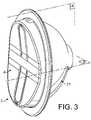
- FIG. 3illustrates a perspective view of a capsule according to a second embodiment of the invention
- FIG. 4is a cross-sectional view of the capsule of FIG. 3 along median vertical plane A;
- FIG. 5is a perspective external view of the cover or lid of the capsule of FIG. 4 ;
- FIG. 6is a perspective internal view of the cover or lid of the capsule of FIG. 5 ;
- FIG. 7is a plane internal view of the cover or lid of FIG. 5 ;
- FIG. 8is a perspective view of the cup-shaped housing or shell of the capsule of FIG. 5 ;
- FIG. 9shows the phase of insertion of the capsule of FIGS. 3 to 8 in the brewing device
- FIG. 10shows the phase of closing of brewing device about the capsule
- FIG. 11shows the phase of creating the overflow aperture of the capsule before brewing in the brewing device
- FIG. 12shows the phase of removal of the capsule from the brewing device
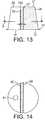
- FIG. 13shows a cross section view of a trunconical capsule according to a third embodiment of the invention.
- FIG. 14shows a cross sectional view in direction I-I of median plane B of the capsule of FIG. 13 ;
- FIG. 15shows a cross sectional view of a rectangular capsule according to a fourth embodiment of the invention.
- FIG. 16shows a cross sectional view in direction II-II of median plane B of the capsule of FIG. 15 ;
- FIG. 17shows a cross sectional view of a capsule according to a fifth embodiment
- FIG. 18shows a cross sectional view in the direction III-III of median plane B of the capsule of FIG. 17 ;
- FIG. 19shows a schematic perspective view of the principle capsule according to a sixth embodiment
- FIG. 20is a cross sectional view of the capsule of FIG. 19 ;
- FIG. 21is a cross sectional view of a variant of the capsule of FIG. 20 .
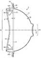
- a capsule system 1comprises a capsule 2 and a beverage brewing device 10 .
- the capsulecomprises an enclosure 20 containing beverage ingredients such as leaf tea and the like.
- the enclosureis demarcated by a cup-shaped housing 21 and a filtering wall 22 that is fixedly attached to peripheral inner step 23 of the housing 21 .
- the enclosureis preferably impermeable to gas and light.
- the housingmay encompass different cross sections such as a circular, ellipsoid, square, rectangular or polygonal section that determine as a matter of fact the general profile of the filtering wall 22 .
- the enclosureis sized to accommodate a dose of leaf beverage ingredient of typically about between 1 to 10 grams, preferably 2 to 5 grams.
- the dose of leaf ingredientmay depend on the final volume of beverage to produce.
- a typical dosecan be of about 2 grams whereas for a tea pot, a typical dose can be of about 8 to 10 grams.
- the capsuleis positioned relative to the brewing device so that the filtering wall 22 extends substantially vertical and from substantially the bottom of the enclosure.
- the capsuleis preferably positioned in a “vertical” arrangement in the brewing device 1 .
- the cup-shaped housing 21can be so oriented with its large opening and its bottom oriented in a vertical position.
- the capsuleis preferably closed by a sealing wall 3 that hermetically closes the enclosure 20 .
- the sealing wallis attached, for instance, to a peripheral outer rim 24 of the cup-shaped housing.
- Both the sealing wall and the housingcan be made of oxygen barrier materials and the enclosure can be substantially free of oxygen so that the freshness of the beverage ingredients can be preserved during an extended period of time.
- the sealing wallcan be a flexible membrane or a semi-rigid plastic part.
- a puncturable sealing membraneis preferred such as a monolayer or a multi-layer membrane, typically, laminates of PET/Aluminium/PP, PE/EVOH/PP, PET/Metallised/PP, Aluminum/PP.
- the enclosureis preferably oxygen free and may contain flushed inert gas such as N2, N2O or CO2.
- the capsulecan further comprise a cover 4 that is also attached to the rim 24 of the housing and overlaps the sealing wall 3 .
- the coverforms an internal channel 40 that terminates at its side end by an outlet 41 .
- the coveris provided with a puncture indicating means 85 in the form of a predefined hole or a weakened or breakable zone.
- the shape of the housing of the capsuleis not very critical. Preference is given to a trunconical, ellipsoidal or hemispherical shapes for different reasons. This allows a larger surface for the exit of the beverage through the sealing wall when perforated and a reduction of the inside pressure.
- the housingcan also be manufactured industrially at lower cost by plastic thermoforming or aluminium deep drawing. This shape with smoother corners also favours the removal of the handling members and so ejection of the capsule.
- the brewing device 10comprises capsule handling members 30 , 31 that are configured to hold the capsule in the “vertical” arrangement as defined.
- These handling members 30 , 31can be machine jaws or any suitable mechanical enclosing means that can open and close about the capsule and can maintain it firmly in place.
- the capsulecan withstand the low brewing pressure therefore the capsule does not necessarily need to be entirely enclosed but simply held water tightly in place during brewing. This participates to a simplification of the machine and it reduces machine costs.
- the brewing devicecomprises a water supply 32 , such as a water tank, a water pump 33 , a heater 34 and a hot water injection line 35 that is managed through the handling member 30 .
- the brewing devicemay also comprise a controller and a user interface board (not shown) to manage the beverage preparation cycles as known in the art.
- a backpressure valve 36can be provided to lower the pressure at the entry side or injection member 38 (such as a needle(s) or blade(s) and a water inlet) in the capsule.
- the backpressure valvecould be omitted and a low pressure pump could be used that delivers fluid at low pressure.
- Medium to high pressure pumpmay however be preferred because of their robustness and reliability and so used in combination with a backpressure valve.
- the brewing devicemay further comprise a means 37 for perforating the sealing wall at an overflow location of the enclosure.
- the perforating means 37can be activated after closing of the handling members 30 , 31 about the capsule.
- the perforating meansis forced or guided through the cover 4 through a puncture indicating means 85 such as a hole having a diameter slightly larger than the perforator.
- the perforatorcan engage the sealing wall 3 in puncturing to create an overflow aperture and then is retracted away from the aperture to leave the aperture fully open.
- the perforatorcan be driven by a solenoid or any other equivalent drive means or even manually.
- the capsulefinally comprises an overflow wall 3 with an overflow aperture 25 placed at least above the median horizontal plane P of the enclosure.
- the filtering wall 22 and the overflow wall 3are spaced apart a short distance sufficient to create an interstitial space “s” that is supposed, without being bound by theory, to work as a sort of “siphon” that can promote the upward motion of the denser beverage portion that is predominantly localized in the bottom of the enclosure.
- the method of the inventionworks as follows.
- a capsuleis inserted in the brewing device and the capsule handling members are closed about the capsule to position it with the sealing wall being substantially vertically oriented.
- An overflow apertureis created by the perforating means 37 that punctures the sealing wall 3 and is withdrawn to leave the aperture opened.
- the fluid injection memberis introduced in the capsule's enclosure. Hot water is thus injected in the capsule at relatively low pressure, preferably, at a pressure not exceeding 0.2 bar. Hot water slowly fills the capsule in and submerges the beverage ingredients in the enclosure. The brewed beverage is filtered through the filtering wall 22 .
- a denser portion 5 of the beveragemay tend to settle in the bottom of the enclosure; which portion is also filtered through the filtering wall since it is properly placed adjacent this portion.
- the denser beverageis evacuated through the interstitial space “s” as caused by the variation of pressure between the lower part of the space and the upper part of said space therefore acting similarly to a “siphon”.
- the rest of the beverageis also filtered also by passing through the filtering wall at different vertical levels up to the upper level of the fluid in the enclosure and is evacuated to the overflow aperture 25 .
- the overflow apertureshould preferably be placed above the 3 ⁇ 4 of the total height of the enclosure and even preferably be placed above the 4 ⁇ 5 of the total height of the enclosure; thus ensuring a more complete submergence of the beverage ingredients and a slower evacuation of the beverage from the enclosure which favours a better infusion process.
- total height of the enclosureis meant to be the total distance separating the lowermost point of the enclosure to the uppermost point of the enclosure when the capsule is positioned in the beverage machine ready for the brewing operation.
- the filtering wallcan be substantially equal to the total height of the enclosure.
- a “direct flow”can be obtained where the brewed liquid is dispensed directly into the recipient 6 (e.g., cup, mug and the like).
- direct flowit is meant that the outlet is arranged in respect to the brewing device so that the brewed liquid does not encounter any permanent device part when leaving the outlet. In other words, the outlet is placed sufficiently low and laterally spaced from the capsule handling members to avoid any significant contact of the liquid with these members when released.
- the principle of the brewing method according to FIGS. 1 and 2encompasses different variants and equivalences.
- the overflow wall 3may not be perforated but may be pre-opened by a pre-cut overflow aperture.
- the pre-cut overflow aperturemeans an aperture which has already been made at the manufacturing stage of the capsule. Freshness of the beverage ingredients may so be preserved by different means such as by an airtight closed cover with a sealed outlet that is unsealed just before brewing or by the use of an airtight overwrap package that encloses the capsule.
- the capsulemay also be conceived without the cover 4 and its channelling function.
- the front handling member 31may be designed to collect the brewed liquid as it passes the overflow wall 3 and travels down to the recipient.
- FIGS. 3 to 8A second embodiment of the capsule of the invention is illustrated in relation to FIGS. 3 to 8 . These figures illustrate a variant of the beverage capsule 2 for carrying out the method of the invention.
- the beverage capsule 2comprises an enclosure 20 for containing one or more beverage ingredients.
- the enclosure 20is defined by the assembly of a cup-shaped shell 21 and a filtering wall 22 .
- a overflow sealing wall 3 Bcloses the shell 21 hermetically and will serve the purpose of the overflow wall as will be explained later on.
- the capsulefurther comprises a cover or lid 4 with a peripheral rim that is attached to the peripheral rim 42 of the housing 21 .
- the connection between the lid and housingcan be made by gluing, welding, snap fitting and any combinations thereof.
- the overflow sealing wall 3 Bmay be constructed of a rigid, semi-rigid, or non-rigid material, or combinations thereof. Suitable materials include, but are not limited to, plastics, PET, aluminum foil, polymeric film, paper, and the like.
- the wallis a flexible membrane made of monolayer or laminate with a gas barrier and oxygen is substantially removed from the enclosure during manufacturing by inert gas flushing or a similar technique, therefore, to maintain freshness of the beverage ingredients before use.
- the lid 4serves as a support for at least one puncture means or puncture indication means 8 .
- the capsulecomprises at least one puncture means 8 positioned relatively to the sealing wall 3 B to be able to produce at least one overflow aperture in the sealing wall.
- the capsulecomprises two puncture means 8 A, 8 B. The need for two puncture means on the capsule will become apparent in the following description, but in simple terms, it enables to use the capsule in two possible orientations in the brewing machine and so provide more convenience to the user in the handling of the capsule.
- the puncture meansare positioned in an off-centred arrangement relative to the median plane B representing the horizontal plane passing by the centre of the enclosure 20 when the capsule is placed in operation in the brewing device 3 .
- the capsulecomprises two series (respectively referenced “A” and “B”) of one puncture means 8 A, 8 B and of one beverage outlet 41 A, 41 B; each series being placed offset relative to the median centre plane B of the sealing exit wall and opposed to each other.
- the two series 8 A, 41 A; 8 B, 41 B of said puncture means and said outletsare placed symmetrically with respect to a median plane (B) passing through the centre plane of the sealing exit wall.
- the capsulecan be so oriented in two possible orientations, at about 180° one another, thus facilitating insertion and placing of the capsule in the machine.
- the number of seriescould exceed two, preferably an even number, for instance, four series which are grouped by two at 90° degrees from each other, so that it offers four different possible orientations in the machine.
- the capsulefurther comprises a filtering wall 22 that is spaced apart a short distance relative to the sealing wall in order to leave an interstitial space “s” there between.
- the filter wallcan be attached by any suitable connection means, such as welding, gluing, snap fitting or any equivalents, to a peripheral stepped portion 23 of the housing.
- the filter mediacan be constructed from a variety of materials including, but not limited to, plastic foil, non-woven polyester, polypropylene, polyethylene, paper materials, and combinations thereof.
- the beverage flow conducting means 40can preferably be positioned adjacent and outside relative to the sealing exit wall.
- the capsulecan be oriented vertically, e.g., its exit sealing wall being vertically oriented, in order for the flow to be directed straight down to the cup via the beverage flow conducting means 40 and the beverage outlet.
- the capsulecan be “direct flow” in the sense that the beverage that leaves the machine falls down directly into the cup without touching any part of the machine. The benefits are so less taste cross-contamination and reduced cleaning.
- the puncture means 8 A, 8 B and the beverage outlets 41 A, 41 Bare respectively placed at two opposite off-centred sites relative to the centre or median plane B of the sealing exit wall or enclosure.
- one of the beverage outlets 8 A, 8 Bbecomes so oriented downwards to release the beverage in a direction that is substantially orthogonal to the direction at which the beverage is released out of the overflow location.
- This configurationenables to orient the capsule in the machine such that the beverage is released in a straight downward direction into the cup thus favouring a “direct flow” without contact with the machine.
- the flow conducting means 40is shared by the two series A, B at once.
- the construction of the capsuleis rationalized and less costly to produce.
- the capsulecan also be shaped to promote and indicate to the user a particular direction for insertion into the brewing device.
- the capsulemore particularly the cover, can be provided with an elongated shape having an axial distance L and a shorter transversal distance W; wherein the at least one puncture means 8 A, 8 B and at least one outlet 41 A, 41 B are placed substantially along the axial distance.
- the puncture means 8 A, 8 Bcomprises two spring-biased mechanical perforating members that are better shown in FIG. 6 .
- Each memberis formed of one resilient plastic tongue 810 made integral with the rest of the lid.
- the tonguesupports at its flexure end 811 an inner spike 812 sufficiently large to create an overflow aperture of sufficient section in the sealing wall.
- the tongueconnects integrally to the surface of the transversal surface of the lid. The two puncture means and outlets are thus aligned along the longer axis of the lid.
- the puncturing means 8 A, 8 B as described and illustratedcan take many other equivalent configurations and they should not be limited to the form as described and shown.
- the resilient plastic tongue 810can be replaced by a spring which is not necessarily made of one piece with the cover.
- the inner spikecan take other shapes. For instance, it could be formed by the conjunction of several separate needles capable of forming multiple small openings. Blades of different shapes such as could also replace the spike triangular, trapezoidal, rectangular, serrated or sinusoidal, etc.
- wall 820 , 821are provided that run parallel to each other and on each side of the puncture means.
- the portion of wall 820extends inwardly and perpendicularly to the recess 81 and comes proximate to the sealing wall 3 . They also preferably run from a point proximate to the two outlets 41 A, 41 B in order to form the inner channel 40 capable of guiding the flow of brewed liquid from the overflow aperture to its respective outlet placed opposite the lid.
- the walls 820 , 821form a guiding channel for the beverage but also rigidify the lid.
- the outlets 41 A, 41 Bcan serve two functions depending on their position during brewing: a first delivery function when the outlet is placed at the bottom of the capsule and a second air venting function when the outlet is placed at the top of the capsule during brewing.
- the guiding channelmay be differently designed, for example, it can be formed of a tubular member which is inserted between the cover 4 and the sealing wall 3 B or which can be an integral part of the cover itself. The tubular member could also extend beyond (above and below) the limits of the cover itself to form portions of duct to help guide the brewed liquid to the cup.
- FIG. 8shows the capsule housing or shell 21 .
- the housingcan be formed of thermoformed; blow moulded or injected plastic such as PP or a PP laminate comprising an oxygen barrier or any suitable food grade polymer or of deep drawn aluminium or aluminium-polymer laminate.
- the housinghas a peripheral rim that extends as a flange to constitute a substantially flat sealing portion onto which can be sealed the sealing wall and snap fitted and/or sealed the cover 4 .
- a small step 23is conceived radially inward to the rim to receive the filter wall that can be sealed or otherwise connected to the flat radial portion of the step.
- the depth of the stepdepends on the thickness of the filter wall and on the control of the interstitial space to provide the siphon effect.
- the filter wallcan range from 0.1 to 1.5 mm whereas the depth of step ranges of from 0.2 to 5 mm whereas the interstitial space ranges of from 0.1 to 3.5 mm.
- the wall of the housingcan comprise a raising zone 26 that constitutes the injection region for the introduction of the fluid in the capsule.
- the raising zoneis so conceived to resist to compressive forces of the injection device 38 and to puncture at its centre more easily.
- puncture meanscould be replaced by mere puncture indication means, for instance, at least one hole provided through the lid that is placed strategically above the median plane of the enclosure to guide an external perforator of the brewing device in a way similar to the embodiment of FIG. 1 .
- the capsulecan have a cover with more than two puncturing means or puncture indications means.
- the covercan be round and comprise four puncture means which are distributed radially at respectively 0, 90, 180 and 270 degrees on the cover thus offering four possible insertion positions for the capsule in the beverage device.
- FIGS. 9 to 12refer to the brewing process and related machine system of the capsule of FIGS. 3 to 8 .
- the advantages of the “vertical” arrangement of the capsule in the brewing devicebecomes even more apparent in relation to these figures in relation to the convenience in the handling of the capsule from insertion to removal.
- the brewing module 3 Bcomprises two main capsule handling members 30 , 31 that cooperate in engagement to close about the capsule 2 .
- a front handling member 31can be fixed relative to the brewing device (not entirely depicted) whereas rear handling member 30 is mobile relative to member 31 .
- the front handling memberhas guiding insertion means 320 that enable to insert the capsule in the brewing device.
- Means 320can be a lateral member comprising two lateral slots 320 placed on each side of the capsule to engage the rim 24 of the capsule.
- the slotcan be slightly slanted toward the front handling member in a manner to progressively bring the capsule near the front handling member as capsule progressively falls down by gravity in the device.
- a retaining means 310is provided at the lower part of the handling member for the capsule to be retained in place once inserted in. A lower portion of the rim 24 of the capsule thus engages an abutting portion of means 310 .
- a mechanical pusher 370that is slidably mounted through a bearing portion 371 of the handling member.
- the mechanical pushercan be associated to an actuating means such as an electromechanical solenoid, a cam or any equivalent means (not shown) that can move the mechanical pusher back and forth through the bearing portion.
- the mechanical pusheris so moveable in two positions; a first retracted position of FIG. 9 in which the free end 372 of the pusher is kept away from the capsule when placed in the device and a second extended position shown by FIG. 11 in which the pusher actually engages the upper puncture means 8 .
- the rear handling member 30comprises a housing 300 having a shape that is substantially complementary to the shell 21 of the capsule.
- the housingincludes at its bottom end a fluid injection member 38 that can be, for instance, a sharp needle 380 traversed by a fluid conduit 381 .
- a glandAt the rear of the rear handling member is located a gland that is connected to a fluid tubing (not shown) linked to the fluid system of the beverage device.
- the housing 300has at its open end a small peripheral recess 301 in which is lodged an annular seal joint 302 that makes the fluid tightness against the back of the stepped rim 24 of the capsule when closing is carried out.
- the rear handling member 30can be moved along a substantially horizontal path by means of a toggle lever system 9 .
- This systemis not going to be described in detail here since many different mechanical or hydraulically assisted closing means can be envisaged by a man skilled in the art to move the handling member in a closing arrangement about the capsule in conjunction with the front handling member.
- FIG. 10shows the rear handling member 30 being displaced by the toggle lever system 9 that extends toward a close position of the brewing device.
- the handling membersopen, i.e., the rear handling member is retracted, which causes the capsule to be slightly pulled back and thus it can fall down by gravity and be discarded.
- FIGS. 13 and 14illustrate another variant of the capsule of the invention that is conceived to be brewed while being positioned “horizontally” in the brewing machine.
- the general brewing principleremains the same as in the preceding examples.
- the capsulecomprises an enclosure 20 containing the one or more ingredients to be brewed.
- the enclosureis demarcated by the trunconical shell 21 , a lower wall 27 and an inner filter wall 22 .
- the filter walltransversally splits the inner volume of the shell in two parts; the enclosure and a second beverage collecting volume 26 .
- the filter wallis placed so that it runs from the two top/bottom ends of the enclosure so that the denser liquid that tends to stay near the bottom can be removed through the filter.
- the lower wall 27can be a circular portion that is attached to the rim 24 of the shell 21 such as by crimping, welding, gluing or combinations thereof. It comprises an overflow wall 3 C that rises upwardly inside the shell in front of the filter and leaves an overflow aperture 255 in a region close to upper bottom of the shell 21 .
- the overflow wallis spaced of a short distance “s” from the filter wall 22 .
- a beverage outlet 41is provided in the collect chamber 26 and through the bottom wall 27 .
- the beverage capsule of FIGS. 15 and 16is brewed in an “horizontal” orientation, i.e., with the bottom wall and outlet 41 facing downwardly. Water is injected at low pressure in the enclosure, preferably from the bottom wall. The brewed liquid flows through the filter wall 22 and is forced to pass the overflow aperture 3 C to the collect chamber 26 then down to the outlet 41 .
- FIGS. 15 and 16illustrate another variant of the capsule that is designed to be brewed according to the method of the invention.
- the capsulepossesses the same features as the capsule of FIGS. 13 and 14 except that it is of a rectangular shape.
- the capsulealso comprises an injection point 29 that can be a pre-scored or weakened portion for the introduction of a water nozzle of the brewing device.
- the weakened zonecan be a plastic part that breaks when forced by the nozzle's introduced therein.
- FIGS. 17 and 18illustrate another possible embodiment of capsule that is designed to be brewed according to the general principle of the invention.
- the overflow wallis a funnel 3D that prolongs the outlet 41 inside the capsule.
- the funnelremains shorter than the total height of the enclosure to leave an upper gap 256 between the end section of the funnel and the upper surface of the capsule to constitute the overflow aperture.
- the supporting structure of the capsulecan encompass many variants such as the one illustrated in this example.
- the capsulehas an inverted U-shaped shell 210 with its bottom wall 211 forming the bottom of the capsule; and is closed by a cover 260 .
- the shellis delimited in two volumes by a planar vertically oriented filtering wall 22 .
- the injection of water in the enclosure 20 that contains the ingredientcan be carried out either through the cover 260 in which case the cover is preferably a puncturable membrane or through the shell 210 (i.e., in the side or bottom).
- FIGS. 19 and 20illustrate another variant in which the capsule is made of concentric tubular elements of progressively decreasing diameters (i.e., respectively, from a first to a third portion).
- the outer body or housing of the capsuleis made of a first tubular body 220 .
- the overflow wallis made of a second tubular portion 3 E of smaller diameter and smaller height.
- the filtering member 22is made of a third tubular portion of smaller diameter and substantially equal height as the outer body.
- This third tubular portioncan be, for instance, a spongy or paper or woven, or nonwoven or sintered plastic tube or a combination thereof.
- the beverage ingredientfills the interior of the third tubular portion that so constitutes the enclosure 20 .
- the outer bodycan be sealed on its upper and lower sides by respectively upper and lower lids 261 , 262 . Owing to the smaller height of the second tubular body, an overflow aperture 257 is performed that can let brewed liquid pass after it has been filtered through the filtering tubular portion 22 .
- the lower lid 262can be made integral with the overflow wall such as in injected plastic.
- the lower lid, overflow wall and first portioncould be made of an integrally moulded plastic as well.
- the first portioncould have a non-tubular shape as well.
- the points O 1 , O 2represent the possible water introduction sites in the capsule. As it shows, the water can be introduced at the upper or lower centre of the capsule through the upper or lower lid straight in the enclosure.
- the points P 1 P 2represent the possible exit point for the brewed beverage.
- the beveragecan possibly be dispensed from the capsule along any suitable location between the first and second tubular portions through the lower lid 262 .
- FIG. 21illustrates another variant of a concentric arrangement of tubular portions of progressively decreasing diameters (i.e., respectively, from a first to a third portion) that differs slightly from the previous in that the enclosure 20 is provided at the outermost annular volume between a first outer portion 220 and a second filter tubular portion 22 .
- a third portion of tube of smaller diameter and smaller heightis placed at the centre to force overflow of the brewed beverage.
- Points O 1 , O 2 , O 3 , O 4represents the possible inlet fluid sites.
- Point P 1represents the possible beverage outlet site.
Landscapes
- Engineering & Computer Science (AREA)
- Mechanical Engineering (AREA)
- Food Science & Technology (AREA)
- Apparatus For Making Beverages (AREA)
Abstract
Description
- the quality of the beverage can be improved, in particular, in relation to the beverage concentration into the cup, the taste and the reduced turbidity,
- the capsule is less complicated and less expensive to produce,
- the beverage delivery is cleaner and it reduces or eliminates the taste cross-contamination and hygiene issues,
- the convenience of the capsule handling, i.e., insertion and collection of the used capsules can be improved.
Claims (30)
Applications Claiming Priority (4)
| Application Number | Priority Date | Filing Date | Title |
|---|---|---|---|
| EP05109566.9 | 2005-10-14 | ||
| EP05109566AEP1775234B1 (en) | 2005-10-14 | 2005-10-14 | Capsule for the preparation of a beverage |
| EP05109566 | 2005-10-14 | ||
| PCT/EP2006/066945WO2007042414A1 (en) | 2005-10-14 | 2006-10-02 | Capsule for the preparation of a beverage |
Publications (2)
| Publication Number | Publication Date |
|---|---|
| US20090220650A1 US20090220650A1 (en) | 2009-09-03 |
| US7981451B2true US7981451B2 (en) | 2011-07-19 |
Family
ID=35787943
Family Applications (1)
| Application Number | Title | Priority Date | Filing Date |
|---|---|---|---|
| US12/089,559Active2028-04-08US7981451B2 (en) | 2005-10-14 | 2006-10-02 | Capsule for the preparation of a beverage |
Country Status (21)
| Country | Link |
|---|---|
| US (1) | US7981451B2 (en) |
| EP (2) | EP1775234B1 (en) |
| JP (1) | JP5043022B2 (en) |
| KR (1) | KR101380071B1 (en) |
| CN (2) | CN101309840B (en) |
| AR (1) | AR058091A1 (en) |
| AT (2) | ATE402882T1 (en) |
| AU (1) | AU2006301370B2 (en) |
| BR (1) | BRPI0617375A2 (en) |
| CA (1) | CA2625295C (en) |
| DE (2) | DE602005008610D1 (en) |
| DK (2) | DK1775234T3 (en) |
| ES (2) | ES2311931T3 (en) |
| NZ (1) | NZ567548A (en) |
| PL (2) | PL1775234T3 (en) |
| PT (2) | PT1775234E (en) |
| RU (2) | RU2404104C2 (en) |
| SI (1) | SI1775234T1 (en) |
| TW (1) | TWI388302B (en) |
| WO (1) | WO2007042414A1 (en) |
| ZA (1) | ZA200804097B (en) |
Cited By (39)
| Publication number | Priority date | Publication date | Assignee | Title |
|---|---|---|---|---|
| US20090320693A1 (en)* | 2006-08-30 | 2009-12-31 | Nestec S.A. | Capsule for brewing a beverage |
| US20100173056A1 (en)* | 2007-06-05 | 2010-07-08 | Nestec S.A. | Method for preparing a beverage or liquid food and system using brewing centrifugal force |
| US20100178404A1 (en)* | 2007-06-05 | 2010-07-15 | Nestec S.A. | Capsule system, device and method for preparing a food liquid contained in a receptacle by centrifugation |
| US20100180775A1 (en)* | 2009-01-22 | 2010-07-22 | Alexandre Kollep | Capsule with delaminatable injection means |
| US20100180774A1 (en)* | 2009-01-22 | 2010-07-22 | Alexandre Kollep | Capsule with integrated piercing member |
| US20100203198A1 (en)* | 2007-06-05 | 2010-08-12 | Alfred Yoakim | Capsule and method for preparing a food liquid by centrifugation |
| US20100206177A1 (en)* | 2006-10-17 | 2010-08-19 | Samar Technologies Ltd. | Assembly comprising an appliance and a disposable capsule for producing a brewed drink, and capsule for such an assembly |
| US20110041702A1 (en)* | 2009-08-19 | 2011-02-24 | Alfred Yoakim | Capsule for the preparation of a coffee extract having a structure facilitating perforation for injection of water |
| US20110183897A1 (en)* | 2007-03-06 | 2011-07-28 | Amgen Inc. | Variant activin receptor polypeptides |
| US20110217421A1 (en)* | 2008-09-02 | 2011-09-08 | Alexandre Perentes | Method for preparing a food liquid contained in a capsule by centrifugation and system adapted for such method |
| USD686916S1 (en) | 2012-10-26 | 2013-07-30 | Printpack Illinois, Inc. | Container with castle-shaped base |
| USD687297S1 (en) | 2012-10-26 | 2013-08-06 | Printpack Illinois, Inc. | Container with castle-shaped base |
| US20140026761A1 (en)* | 2011-01-31 | 2014-01-30 | Sarong Societa' Per Azioni | Capsules and dispensing machine |
| US8658232B2 (en) | 2009-08-28 | 2014-02-25 | Nestec S.A. | Capsule system for the preparation of beverages by centrifugation |
| USD715649S1 (en) | 2013-07-09 | 2014-10-21 | Printpack Illinois, Inc. | Container |
| US9095236B2 (en) | 2008-12-09 | 2015-08-04 | Nestec S.A. | Liquid food preparation system for preparing a liquid food by centrifugation |
| US20150265091A1 (en)* | 2012-10-09 | 2015-09-24 | Nestec S.A. | Beverage machine |
| US20160137402A1 (en)* | 2013-07-10 | 2016-05-19 | Nestec S.A. | Capsule for beverage preparation |
| US9371174B2 (en) | 2009-06-17 | 2016-06-21 | Koninklijke Douwe Egberts B.V. | Capsule for preparing a pre-determined quantity of beverage |
| US20160174759A1 (en)* | 2013-07-17 | 2016-06-23 | Nestec S.A. | Food or beverage preparation machine with antiscaling pipe system |
| US9434532B2 (en) | 2007-06-05 | 2016-09-06 | Nestec S.A. | Capsule for preparing a beverage or food liquid and system using brewing centrifugal force |
| US9657155B2 (en) | 2013-04-12 | 2017-05-23 | Printpack Illinois, Inc. | Containers and materials with improved punctureability |
| USD798718S1 (en) | 2014-06-10 | 2017-10-03 | Printpack Illinois, Inc. | Container with cone-shaped base |
| US9783361B2 (en) | 2013-03-14 | 2017-10-10 | Starbucks Corporation | Stretchable beverage cartridges and methods |
| US9877495B2 (en) | 2015-01-09 | 2018-01-30 | Starbucks Corporation | Method of making a sweetened soluble beverage product |
| US9919864B2 (en) | 2010-06-11 | 2018-03-20 | Koninklijke Douwe Egberts B.V. | Cartridge and method for the preparation of beverages |
| US10336498B2 (en) | 2014-06-10 | 2019-07-02 | Printpack Illinois, Inc. | Container with improved punctureability |
| US10343838B2 (en) | 2012-06-18 | 2019-07-09 | K-Fee System Gmbh | Portion capsule and use of same for producing a beverage |
| US10442610B2 (en) | 2014-03-11 | 2019-10-15 | Starbucks Corporation | Pod-based restrictors and methods |
| US10472165B2 (en) | 2012-12-14 | 2019-11-12 | K-Fee System Gmbh | Portion capsule and method for producing a beverage by means of a portion capsule |
| US10669093B2 (en) | 2015-02-27 | 2020-06-02 | K-Fee System Gmbh | Single serve capsule comprising a filter element connected thereto by sealing |
| US10737876B2 (en) | 2015-07-13 | 2020-08-11 | K-Fee System Gmbh | Filter element having a cut-out |
| US10858176B2 (en) | 2010-07-22 | 2020-12-08 | K-Fee System Gmbh | Portion capsule having an identifier |
| US11027913B2 (en)* | 2015-12-31 | 2021-06-08 | Tuttoespresso S.R.L. | Capsule assembly comprising a capsule and a conveyor cap configured to open said capsule |
| US11040823B2 (en) | 2015-02-27 | 2021-06-22 | Bisio Progetti S.P.A. | Capsule for the preparation of infused or soluble beverages |
| US11045035B2 (en) | 2015-09-18 | 2021-06-29 | K-Fee System Gmbh | Adapter for a single serve capsule |
| US11084650B2 (en) | 2015-06-10 | 2021-08-10 | K-Fee System Gmbh | Portion capsule with a three-ply nonwoven fabric |
| US11524268B2 (en) | 2016-11-09 | 2022-12-13 | Pepsico, Inc. | Carbonated beverage makers, methods, and systems |
| US12227323B2 (en) | 2018-07-27 | 2025-02-18 | Gcs German Capsule Solution Gmbh | Method for producing a portion capsule |
Families Citing this family (81)
| Publication number | Priority date | Publication date | Assignee | Title |
|---|---|---|---|---|
| EP1495702A1 (en) | 2003-07-10 | 2005-01-12 | Nestec S.A. | Device for the extraction of a cartridge |
| KR20090027637A (en)* | 2006-05-17 | 2009-03-17 | 코닌클리케 필립스 일렉트로닉스 엔.브이. | Disposable cartridge for beverage maker having movable needle member |
| NL2000400C2 (en)* | 2006-12-22 | 2008-06-24 | Friesland Brands Bv | Cup for concentrate and method for preparation of a liquid product. |
| CN102133047B (en) | 2007-10-04 | 2014-04-30 | 雀巢产品技术援助有限公司 | Heating device with an integrated thermoblock for a beverage preparation machine |
| CL2008002963A1 (en) | 2007-10-04 | 2010-01-22 | Nestec Sa | Heating device for a machine for the preparation of liquid food or drink, comprising a thermal unit with a metallic mass, through which the liquid circulates, and accumulates heat and supplies it to the liquid, and has one or more insured electrical components rigidly to the thermal unit; and machine. |
| EP2218369B1 (en) | 2007-10-04 | 2017-05-03 | Nestec S.A. | Beverage brewing unit |
| PT2080454E (en) | 2008-01-18 | 2010-08-27 | Nestec Sa | Beverage machine and piercing member for an opening device of a beverage machine |
| JP2011518015A (en) | 2008-04-22 | 2011-06-23 | ネステク ソシエテ アノニム | Module assembly for beverage production equipment |
| PT2431301E (en)* | 2008-04-30 | 2013-12-26 | Nestec Sa | Sealed capsule for containing beverage ingredients and having an inlet-side membrane |
| AU2009245745A1 (en) | 2008-05-08 | 2009-11-12 | Nestec S.A. | Beverage production device |
| EP2309900B1 (en) | 2008-08-08 | 2015-05-27 | Nestec S.A. | Beverage machine with carrying handle and configurable appearance&side functions |
| AU2009289682B2 (en) | 2008-09-02 | 2016-06-09 | Société des Produits Nestlé S.A. | Controlled beverage production device using centrifugal forces |
| WO2010032271A1 (en)* | 2008-09-18 | 2010-03-25 | Saeco Ipr Limited | Infusion device for coffee machines and the like |
| DK2384133T3 (en)* | 2008-12-30 | 2013-07-01 | Nestec Sa | PROCEDURE FOR USING TEA LEAVES CONTAINED IN A Capsule |
| EP2230195B1 (en)* | 2009-03-19 | 2018-04-25 | Nestec S.A. | Capsule with filtering insert for preparing a coffee beverage |
| DK2687446T3 (en) | 2009-04-15 | 2015-08-24 | Luna Technology Systems Lts Gmbh | A process for preparing a capsule for an extraction material |
| PL2424794T3 (en)* | 2009-04-27 | 2020-03-31 | Koninklijke Douwe Egberts B.V. | A pad for preparing a beverage, a container comprising several pads, an apparatus and a method for preparing the beverage |
| WO2010128051A1 (en)* | 2009-05-05 | 2010-11-11 | Nestec S.A. | Capsule for preparing a nutritional product including a filter and method |
| EP2865613B1 (en) | 2009-06-17 | 2017-09-06 | Koninklijke Douwe Egberts B.V. | System, method and capsule for preparing a beverage |
| ES2556265T3 (en)* | 2009-06-17 | 2016-01-14 | Nestec S.A. | Opening means for a capsule-based beverage preparation device |
| US8999421B2 (en)* | 2010-03-13 | 2015-04-07 | Bunn-O-Matic Corporation | Cartridge retaining device, brewer in combination with same, and method of using said device |
| US9161658B2 (en) | 2010-03-13 | 2015-10-20 | Bunn-O-Matic Corporation | Single cup brewer |
| CA2800918C (en)* | 2010-05-28 | 2017-10-17 | K-Fee System Gmbh | Portion capsule for producing a beverage |
| JP2013533012A (en)* | 2010-06-18 | 2013-08-22 | ビセルコン ホールディングス リミテッド | Capsule, apparatus and method for preparing beverages by extraction |
| RU2589576C2 (en)* | 2010-08-13 | 2016-07-10 | Конинклейке Филипс Электроникс Н.В. | Brewing device for food product preparation |
| DE102010047890B4 (en) | 2010-08-16 | 2019-05-29 | K-Fee System Gmbh | Portion capsule with a filter fabric |
| US9555958B2 (en) | 2010-09-15 | 2017-01-31 | Nestec S.A. | Method for preparing a beverage from a capsule, capsule and beverage preparing system |
| EP2646347B1 (en)* | 2010-11-30 | 2014-12-17 | Nestec S.A. | Capsule and method for the preparation of a beverage by centrifugation |
| ITBO20110101A1 (en)* | 2011-03-02 | 2012-09-03 | Macchiavelli Srl | INTERCHANGEABLE CAPSULE FOR THE PREPARATION OF A COFFEE INFUSION, AND PROCEDURE FOR OBTAINING AN INFUSION OF SUCH A COFFEE |
| USD694620S1 (en) | 2011-03-08 | 2013-12-03 | Kraft Foods R&D, Inc. | Beverage cartridge |
| GB2488799A (en) | 2011-03-08 | 2012-09-12 | Kraft Foods R & D Inc | Drinks Pod without Piercing of Outer Shell |
| GB2489409B (en) | 2011-03-23 | 2013-05-15 | Kraft Foods R & D Inc | A capsule and a system for, and a method of, preparing a beverage |
| GB201110848D0 (en)* | 2011-06-24 | 2011-08-10 | Mars Inc | Beverage preparation apparatus and method and beverage capsules for use therein |
| GB201112058D0 (en) | 2011-07-13 | 2011-08-31 | Mars Inc | Beverage preparation capsules |
| JP2014526325A (en) | 2011-09-16 | 2014-10-06 | ネステク ソシエテ アノニム | Clean multi-system beverage machine |
| BR112014005798A2 (en) | 2011-09-16 | 2017-03-28 | Nestec Sa | secure multi-system beverage machine connector |
| JP2014530035A (en) | 2011-09-16 | 2014-11-17 | ネステク ソシエテ アノニム | Multiple connections for multi-system beverage machines |
| CA2849950A1 (en) | 2011-09-26 | 2013-04-04 | Nestec S.A. | Hot beverage production device |
| ES2894848T3 (en) | 2011-11-15 | 2022-02-16 | Nestle Sa | Support and capsule for preparing a drink by centrifugation, system and method for preparing a drink by centrifugation |
| ES2546531T3 (en) | 2011-12-30 | 2015-09-24 | Nestec S.A. | A machine for drinks with multiple systems |
| EP2838815B1 (en)* | 2012-04-11 | 2016-01-13 | Koninklijke Philips N.V. | Beverage producing system and capsule |
| FR2990835B1 (en)* | 2012-05-24 | 2016-02-19 | Seb Sa | INFUSION BOX FOR A BEVERAGE MACHINE |
| RU2018108414A (en) | 2012-06-29 | 2019-02-25 | К-Фее Зюстем Гмбх | PORTION CAPSULE WITH IDENTIFIER ON THE MEMBRANE FILM CONNECTED |
| US20150150409A1 (en) | 2012-07-06 | 2015-06-04 | Conopco, Inc., D/B/A/ Unilever | Capsule recognition system |
| USD708057S1 (en) | 2012-09-10 | 2014-07-01 | Kraft Foods R & D, Inc. | Beverage cartridge |
| USD697797S1 (en) | 2012-09-12 | 2014-01-21 | Kraft Foods R&D, Inc. | Beverage cartridge |
| SG11201502160RA (en)* | 2012-10-05 | 2015-05-28 | Nestec Sa | Check valve, injection assembly, and beverage preparation machine. |
| JP2016500529A (en)* | 2012-10-12 | 2016-01-14 | ネステク ソシエテ アノニム | Food capsule with multiple compartments |
| ITBO20130056A1 (en)* | 2013-02-11 | 2014-08-12 | Neronobile S R L | CAPSULE AND METHOD FOR THE PREPARATION OF DRINKS |
| US9527717B2 (en) | 2013-03-12 | 2016-12-27 | Keurig Green Mountain, Inc. | Beverage machine outlet |
| USD732387S1 (en) | 2013-03-21 | 2015-06-23 | Conopco, Inc. | Capsule |
| WO2014146952A1 (en) | 2013-03-21 | 2014-09-25 | Unilever Plc | Method, device and capsule for brewing a beverage |
| USD732386S1 (en)* | 2013-03-21 | 2015-06-23 | Conopco, Inc. | Capsule |
| CN105307954A (en) | 2013-06-25 | 2016-02-03 | 雀巢产品技术援助有限公司 | Cover for a beverage capsule |
| CN105792711A (en)* | 2013-11-22 | 2016-07-20 | 荷兰联合利华有限公司 | Device and method for brewing a beverage |
| US10231573B2 (en) | 2013-12-23 | 2019-03-19 | Nestec S.A. | Simple ergonomic user-interface for a beverage machine |
| EP2889223A1 (en)* | 2013-12-24 | 2015-07-01 | Luna Technology Systems LTS GmbH | Portion capsule for preparing a brewed product |
| CH709295A1 (en)* | 2014-02-21 | 2015-08-28 | Delica Ag | Capsule with a preferably rotationally symmetrical capsule body. |
| CN104071467A (en)* | 2014-06-26 | 2014-10-01 | 浙江爱仕达生活电器有限公司 | Beverage capsule of modified structure and use method thereof |
| JP2017531476A (en) | 2014-10-01 | 2017-10-26 | クラフト・フーズ・グループ・ブランズ・エルエルシー | Coffee pod |
| USD757536S1 (en) | 2014-10-01 | 2016-05-31 | Kraft Foods Group Brands Llc | Container |
| CA3207639A1 (en) | 2014-10-20 | 2016-04-28 | Bedford Systems Llc | Cartridge holder for beverage machine |
| WO2016106433A1 (en) | 2014-12-30 | 2016-07-07 | Moradi Consulting Gmbh | Discharging element in the form of a capsule for discharging additives into a liquid |
| CN104605474B (en)* | 2015-01-22 | 2018-03-30 | 广东新宝电器股份有限公司 | Food capsule brewing device, beverage brewing method and food capsule |
| CN104758175B (en)* | 2015-03-12 | 2018-12-18 | 李绍平 | A kind of preparation method of traditional Chinese herbal decoction |
| CN106185065B (en)* | 2015-05-04 | 2019-02-22 | 宁波金阳光电热科技有限公司 | Interior puncture type drink capsule |
| DE102015011169B4 (en)* | 2015-09-01 | 2018-12-20 | LigaLife GmbH & Co. KG | Capsule for a production of a liquid food |
| KR102422869B1 (en) | 2016-07-26 | 2022-07-19 | 소시에떼 데 프로듀이 네슬레 소시에떼아노님 | Capsule and Beverage Manufacturing Systems |
| JP7008038B2 (en) | 2016-07-26 | 2022-01-25 | ソシエテ・デ・プロデュイ・ネスレ・エス・アー | Capsule and beverage generation system |
| KR102422867B1 (en) | 2016-07-26 | 2022-07-19 | 소시에떼 데 프로듀이 네슬레 소시에떼아노님 | Capsules for making beverages |
| DE102017002401A1 (en)* | 2017-03-07 | 2018-09-13 | Kocher-Plastik Maschinenbau Gmbh | Plastic container product |
| CN110769726A (en) | 2017-05-03 | 2020-02-07 | 雀巢产品有限公司 | Method for preparing tea |
| CN109588982B (en)* | 2017-09-30 | 2022-02-01 | 广东美的生活电器制造有限公司 | Beverage capsule |
| CN110589257B (en)* | 2018-06-12 | 2022-03-08 | 广东美的生活电器制造有限公司 | Film cutting discs, capsules and beverage machines |
| IT201800007403A1 (en)* | 2018-07-20 | 2020-01-20 | CAPSULE FOR THE PREPARATION OF A BEVERAGE | |
| CN114341023B (en)* | 2019-05-31 | 2024-08-16 | 吴星 | Beverage capsules |
| CA3161792A1 (en)* | 2019-12-18 | 2021-06-24 | Societe Des Produits Nestle S.A. | Container with a plant material for preparing a tea beverage |
| CN111938429A (en)* | 2020-07-24 | 2020-11-17 | 六安索伊电器制造有限公司 | Extraction device of coffee machine |
| EP4489622A1 (en) | 2022-03-07 | 2025-01-15 | Société des Produits Nestlé S.A. | Beverage preparation machine |
| WO2023170084A1 (en) | 2022-03-07 | 2023-09-14 | Société des Produits Nestlé S.A. | Beverage preparation system |
| CN118843409A (en) | 2022-03-07 | 2024-10-25 | 雀巢产品有限公司 | Beverage preparation machine |
Citations (13)
| Publication number | Priority date | Publication date | Assignee | Title |
|---|---|---|---|---|
| GB1397116A (en) | 1971-06-11 | 1975-06-11 | Jacobs Joh & Co | Preparation of a filtered beverage |
| DE2645885B1 (en) | 1976-10-12 | 1977-07-28 | Melitta-Werke Bentz & Sohn, 4950 Minden | Tea filter with overflow trap - has hollow closing rod with overflow opening beneath level of filter vessel when inserted in position |
| FR2617389A1 (en) | 1987-06-30 | 1989-01-06 | Desaltera | FILTER CARTRIDGE AND MACHINE FOR THE PREPARATION OF AN EXPRESS BEVERAGE |
| EP0468079A1 (en) | 1990-07-27 | 1992-01-29 | Societe Des Produits Nestle S.A. | Closed cartridge for making a beverage, process and device for manufacturing such a cartridge |
| EP0512470A1 (en) | 1991-05-08 | 1992-11-11 | Societe Des Produits Nestle S.A. | Method of producing beverages using sealed cartridges and apparatus for carrying out this method |
| EP0512468A1 (en) | 1991-05-10 | 1992-11-11 | Societe Des Produits Nestle S.A. | Closed cartridge for making a beverage |
| EP0615921A1 (en) | 1993-03-17 | 1994-09-21 | General Foods Limited | Rigid cartridge for coffee or the like |
| EP1101430A1 (en) | 1999-11-16 | 2001-05-23 | Robert Hale | Beverage filter cartridge system |
| US20020148356A1 (en) | 2001-04-11 | 2002-10-17 | Lazaris Nicholas G. | Beverage filter cartridge holder |
| US20020148357A1 (en) | 2001-04-11 | 2002-10-17 | Lazaris Nicholas G. | Beverage filter cartridge holder |
| US20030005826A1 (en)* | 2001-03-16 | 2003-01-09 | Sargent Jeffrey Alan | Beverage brewing devices for preparing creamy beverages |
| EP1440904A1 (en) | 2003-01-24 | 2004-07-28 | Kraft Foods R & D, Inc. | Cartridge for the preparation of beverages and method of manufacturing a cartridge |
| US20050115415A1 (en)* | 2003-12-01 | 2005-06-02 | Corey Arrick | Capsule with foam conditioning feature |
Family Cites Families (12)
| Publication number | Priority date | Publication date | Assignee | Title |
|---|---|---|---|---|
| NL8300451A (en)* | 1983-02-07 | 1984-09-03 | Philips Nv | FILTERING DEVICE. |
| ATE93373T1 (en)* | 1990-07-27 | 1993-09-15 | Nestle Sa | METHOD FOR BREWING CLOSED PORTION PACKS AND APPARATUS FOR CARRYING OUT THESE METHOD. |
| ES2080196T3 (en)* | 1991-07-05 | 1996-02-01 | Nestle Sa | DEVICE FOR THE EXTRACTION OF CARTRIDGES. |
| US5567461A (en)* | 1994-05-09 | 1996-10-22 | Robert Lehrer Associates, Inc. | Method of treating fluids with a filter |
| DK1808382T3 (en)* | 2002-01-16 | 2013-03-25 | Nestle Sa | Closed capsule with a beaker with opening means |
| DE10211327B4 (en)* | 2002-03-14 | 2015-09-24 | Caffitaly System S.P.A. | Portion capsule with a particulate extractable by water substance for the preparation of a beverage |
| EP1549186A1 (en)* | 2002-09-20 | 2005-07-06 | Nestec S.A. | Method, device, and capsule for preparing a foamy liquid food |
| GB2397500B (en)* | 2003-01-24 | 2005-03-23 | Kraft Foods R & D Inc | Cartridge for the preparation of beverages |
| CN2615077Y (en)* | 2003-03-12 | 2004-05-12 | 吕昭明 | Infusion Drink Containers |
| ATE373438T1 (en)* | 2003-07-23 | 2007-10-15 | Nestec Sa | DEVICE AND METHOD FOR DISPENSING BEVERAGES WITH DIFFERENT QUANTITIES OF FOAM FROM CAPSULES |
| US20050051478A1 (en)* | 2003-09-10 | 2005-03-10 | Basil Karanikos | Beverage filter cartridge |
| WO2005092160A1 (en)* | 2004-03-26 | 2005-10-06 | Illycaffe's.P.A. | Integrated cartridge for extracting a beverage from a particulate substance |
- 2005
- 2005-10-14SISI200530368Tpatent/SI1775234T1/enunknown
- 2005-10-14EPEP05109566Apatent/EP1775234B1/ennot_activeExpired - Lifetime
- 2005-10-14DKDK05109566Tpatent/DK1775234T3/enactive
- 2005-10-14PLPL05109566Tpatent/PL1775234T3/enunknown
- 2005-10-14PTPT05109566Tpatent/PT1775234E/enunknown
- 2005-10-14ATAT05109566Tpatent/ATE402882T1/enactive
- 2005-10-14ESES05109566Tpatent/ES2311931T3/ennot_activeExpired - Lifetime
- 2005-10-14DEDE602005008610Tpatent/DE602005008610D1/ennot_activeExpired - Lifetime
- 2006
- 2006-10-02CNCN2006800425537Apatent/CN101309840B/ennot_activeExpired - Fee Related
- 2006-10-02AUAU2006301370Apatent/AU2006301370B2/ennot_activeCeased
- 2006-10-02PLPL06806909Tpatent/PL1951593T3/enunknown
- 2006-10-02RURU2008118881/12Apatent/RU2404104C2/ennot_activeIP Right Cessation
- 2006-10-02CACA2625295Apatent/CA2625295C/ennot_activeExpired - Fee Related
- 2006-10-02WOPCT/EP2006/066945patent/WO2007042414A1/enactiveApplication Filing
- 2006-10-02PTPT06806909Tpatent/PT1951593E/enunknown
- 2006-10-02JPJP2008534980Apatent/JP5043022B2/enactiveActive
- 2006-10-02DKDK06806909.5Tpatent/DK1951593T3/enactive
- 2006-10-02RURU2010130269/12Apatent/RU2530850C2/enactive
- 2006-10-02BRBRPI0617375-6Apatent/BRPI0617375A2/ennot_activeIP Right Cessation
- 2006-10-02NZNZ567548Apatent/NZ567548A/ennot_activeIP Right Cessation
- 2006-10-02EPEP06806909Apatent/EP1951593B1/enactiveActive
- 2006-10-02DEDE602006015997Tpatent/DE602006015997D1/enactiveActive
- 2006-10-02ESES06806909Tpatent/ES2348073T3/enactiveActive
- 2006-10-02ATAT06806909Tpatent/ATE476377T1/enactive
- 2006-10-02CNCN2010102595371Apatent/CN101905787B/ennot_activeExpired - Fee Related
- 2006-10-02USUS12/089,559patent/US7981451B2/enactiveActive
- 2006-10-02KRKR1020087011404Apatent/KR101380071B1/ennot_activeExpired - Fee Related
- 2006-10-13ARARP060104505Apatent/AR058091A1/enunknown
- 2006-10-13TWTW095137804Apatent/TWI388302B/ennot_activeIP Right Cessation
- 2008
- 2008-05-13ZAZA200804097Apatent/ZA200804097B/enunknown
Patent Citations (13)
| Publication number | Priority date | Publication date | Assignee | Title |
|---|---|---|---|---|
| GB1397116A (en) | 1971-06-11 | 1975-06-11 | Jacobs Joh & Co | Preparation of a filtered beverage |
| DE2645885B1 (en) | 1976-10-12 | 1977-07-28 | Melitta-Werke Bentz & Sohn, 4950 Minden | Tea filter with overflow trap - has hollow closing rod with overflow opening beneath level of filter vessel when inserted in position |
| FR2617389A1 (en) | 1987-06-30 | 1989-01-06 | Desaltera | FILTER CARTRIDGE AND MACHINE FOR THE PREPARATION OF AN EXPRESS BEVERAGE |
| EP0468079A1 (en) | 1990-07-27 | 1992-01-29 | Societe Des Produits Nestle S.A. | Closed cartridge for making a beverage, process and device for manufacturing such a cartridge |
| EP0512470A1 (en) | 1991-05-08 | 1992-11-11 | Societe Des Produits Nestle S.A. | Method of producing beverages using sealed cartridges and apparatus for carrying out this method |
| EP0512468A1 (en) | 1991-05-10 | 1992-11-11 | Societe Des Produits Nestle S.A. | Closed cartridge for making a beverage |
| EP0615921A1 (en) | 1993-03-17 | 1994-09-21 | General Foods Limited | Rigid cartridge for coffee or the like |
| EP1101430A1 (en) | 1999-11-16 | 2001-05-23 | Robert Hale | Beverage filter cartridge system |
| US20030005826A1 (en)* | 2001-03-16 | 2003-01-09 | Sargent Jeffrey Alan | Beverage brewing devices for preparing creamy beverages |
| US20020148356A1 (en) | 2001-04-11 | 2002-10-17 | Lazaris Nicholas G. | Beverage filter cartridge holder |
| US20020148357A1 (en) | 2001-04-11 | 2002-10-17 | Lazaris Nicholas G. | Beverage filter cartridge holder |
| EP1440904A1 (en) | 2003-01-24 | 2004-07-28 | Kraft Foods R & D, Inc. | Cartridge for the preparation of beverages and method of manufacturing a cartridge |
| US20050115415A1 (en)* | 2003-12-01 | 2005-06-02 | Corey Arrick | Capsule with foam conditioning feature |
Non-Patent Citations (1)
| Title |
|---|
| Written Opinion of the International Searching Authority (5 pgs.). |
Cited By (84)
| Publication number | Priority date | Publication date | Assignee | Title |
|---|---|---|---|---|
| US20090320693A1 (en)* | 2006-08-30 | 2009-12-31 | Nestec S.A. | Capsule for brewing a beverage |
| US8512886B2 (en)* | 2006-08-30 | 2013-08-20 | Nestec S.A. | Capsule for brewing a beverage |
| US20100206177A1 (en)* | 2006-10-17 | 2010-08-19 | Samar Technologies Ltd. | Assembly comprising an appliance and a disposable capsule for producing a brewed drink, and capsule for such an assembly |
| US20110183897A1 (en)* | 2007-03-06 | 2011-07-28 | Amgen Inc. | Variant activin receptor polypeptides |
| US9968111B2 (en) | 2007-06-05 | 2018-05-15 | Nestec S.A. | Capsule and method for preparing a food liquid by centrifugation |
| US8986764B2 (en) | 2007-06-05 | 2015-03-24 | Nestec S.A. | Capsule and method for preparing a food liquid by centrifugation |
| US20100203198A1 (en)* | 2007-06-05 | 2010-08-12 | Alfred Yoakim | Capsule and method for preparing a food liquid by centrifugation |
| US20100203208A1 (en)* | 2007-06-05 | 2010-08-12 | Alfred Yoakim | Method for preparing a food liquid contained in a capsule by centrifugation and device adapted for such method |
| US9277837B2 (en) | 2007-06-05 | 2016-03-08 | Nestec S.A. | Method for preparing a beverage or liquid food and system using brewing centrifugal force |
| US9271598B2 (en) | 2007-06-05 | 2016-03-01 | Nestec S.A. | Method for preparing a food liquid contained in a capsule by centrifugation and device adapted for such method |
| US9226611B2 (en) | 2007-06-05 | 2016-01-05 | Nestec S.A. | Capsule system, device and method for preparing a food liquid contained in a receptacle by centrifugation |
| US9434532B2 (en) | 2007-06-05 | 2016-09-06 | Nestec S.A. | Capsule for preparing a beverage or food liquid and system using brewing centrifugal force |
| US9603479B2 (en) | 2007-06-05 | 2017-03-28 | Nestec S.A. | Capsule for preparing a beverage or liquid food and system using brewing centrifugal force |
| US20100186599A1 (en)* | 2007-06-05 | 2010-07-29 | Alfred Yoakim | Capsule for preparing a beverage or liquid food and system using brewing centrifugal force |
| US9731892B2 (en) | 2007-06-05 | 2017-08-15 | Nestec S.A. | Capsule and method for preparing a food liquid by centrifugation |
| US8813634B2 (en) | 2007-06-05 | 2014-08-26 | Nestec S.A. | Capsule for preparing a beverage or liquid food and system using brewing centrifugal force |
| US20100178404A1 (en)* | 2007-06-05 | 2010-07-15 | Nestec S.A. | Capsule system, device and method for preparing a food liquid contained in a receptacle by centrifugation |
| US20100173056A1 (en)* | 2007-06-05 | 2010-07-08 | Nestec S.A. | Method for preparing a beverage or liquid food and system using brewing centrifugal force |
| US9743799B2 (en) | 2007-06-05 | 2017-08-29 | Nestec S.A. | Method for preparing a beverage or liquid food and system using brewing centrifugal force |
| US8919242B2 (en) | 2008-09-02 | 2014-12-30 | Nestec S.A. | Method for preparing a food liquid contained in a capsule by centrifugation and system adapted for such method |
| US20110217421A1 (en)* | 2008-09-02 | 2011-09-08 | Alexandre Perentes | Method for preparing a food liquid contained in a capsule by centrifugation and system adapted for such method |
| US9095236B2 (en) | 2008-12-09 | 2015-08-04 | Nestec S.A. | Liquid food preparation system for preparing a liquid food by centrifugation |
| US8402883B2 (en) | 2009-01-22 | 2013-03-26 | Nestec S.A. | Capsule with delaminatable injection means |
| US8393261B2 (en)* | 2009-01-22 | 2013-03-12 | Nestec S.A. | Capsule with integrated piercing member |
| US20100180775A1 (en)* | 2009-01-22 | 2010-07-22 | Alexandre Kollep | Capsule with delaminatable injection means |
| US20100180774A1 (en)* | 2009-01-22 | 2010-07-22 | Alexandre Kollep | Capsule with integrated piercing member |
| US9371174B2 (en) | 2009-06-17 | 2016-06-21 | Koninklijke Douwe Egberts B.V. | Capsule for preparing a pre-determined quantity of beverage |
| US9162815B2 (en) | 2009-08-19 | 2015-10-20 | Nestec S.A. | Capsule for the preparation of a coffee extract having a structure facilitating perforation for injection of water |
| US20110041702A1 (en)* | 2009-08-19 | 2011-02-24 | Alfred Yoakim | Capsule for the preparation of a coffee extract having a structure facilitating perforation for injection of water |
| US8658232B2 (en) | 2009-08-28 | 2014-02-25 | Nestec S.A. | Capsule system for the preparation of beverages by centrifugation |
| US9919864B2 (en) | 2010-06-11 | 2018-03-20 | Koninklijke Douwe Egberts B.V. | Cartridge and method for the preparation of beverages |
| US11667465B2 (en) | 2010-07-22 | 2023-06-06 | K-Fee System Gmbh | Portion capsule having an identifier |
| US11554910B2 (en) | 2010-07-22 | 2023-01-17 | K-Fee System Gmbh | Portion capsule having an identifier |
| US11919703B2 (en) | 2010-07-22 | 2024-03-05 | K-Fee System Gmbh | Portion capsule having an identifier |
| US20210086986A1 (en) | 2010-07-22 | 2021-03-25 | K-Fee System Gmbh | Portion capsule having an identifier |
| US10870531B2 (en) | 2010-07-22 | 2020-12-22 | K-Fee System Gmbh | Portion capsule having an identifier |
| US10858177B2 (en) | 2010-07-22 | 2020-12-08 | K-Fee System Gmbh | Portion capsule having an identifier |
| US10858176B2 (en) | 2010-07-22 | 2020-12-08 | K-Fee System Gmbh | Portion capsule having an identifier |
| US11230430B2 (en) | 2010-07-22 | 2022-01-25 | K-Fee System Gmbh | Portion capsule having an identifier |
| US11820586B2 (en) | 2010-07-22 | 2023-11-21 | K-Fee System Gmbh | Portion capsule having an identifier |
| US11254491B2 (en) | 2010-07-22 | 2022-02-22 | K-Fee System Gmbh | Portion capsule having an identifier |
| US11465829B2 (en) | 2010-07-22 | 2022-10-11 | K-Fee System Gmbh | Portion capsule having an identifier |
| US11465830B2 (en) | 2010-07-22 | 2022-10-11 | K-Fee System Gmbh | Portion capsule having an identifier |
| US11542094B2 (en) | 2010-07-22 | 2023-01-03 | K-Fee System Gmbh | Portion capsule having an identifier |
| US11548722B2 (en) | 2010-07-22 | 2023-01-10 | K-Fee System Gmbh | Portion capsule having an identifier |
| US10994923B2 (en) | 2010-07-22 | 2021-05-04 | K-Fee System Gmbh | Portion capsule having an identifier |
| US10011421B2 (en)* | 2011-01-31 | 2018-07-03 | Sarong Societa' Per Azioni | Capsules and dispensing machine |
| US20140026761A1 (en)* | 2011-01-31 | 2014-01-30 | Sarong Societa' Per Azioni | Capsules and dispensing machine |
| US12151876B2 (en) | 2012-06-18 | 2024-11-26 | K-Fee System Gmbh | Methods of making and using a portion capsule |
| US10343838B2 (en) | 2012-06-18 | 2019-07-09 | K-Fee System Gmbh | Portion capsule and use of same for producing a beverage |
| US11702276B2 (en) | 2012-06-18 | 2023-07-18 | K-Fee System Gmbh | Portion capsule for preparing a beverage |
| US11312567B2 (en) | 2012-06-18 | 2022-04-26 | K-Fee System Gmbh | Portion and method for producing a beverage by means of a portion capsule |
| US20150265091A1 (en)* | 2012-10-09 | 2015-09-24 | Nestec S.A. | Beverage machine |
| USD700839S1 (en) | 2012-10-26 | 2014-03-11 | Printpack Illinois, Inc. | Container with castle-shaped base |
| USD686916S1 (en) | 2012-10-26 | 2013-07-30 | Printpack Illinois, Inc. | Container with castle-shaped base |
| USD687297S1 (en) | 2012-10-26 | 2013-08-06 | Printpack Illinois, Inc. | Container with castle-shaped base |
| USD730174S1 (en) | 2012-10-26 | 2015-05-26 | Printpack Illinois, Inc. | Container with castle-shaped base |
| US10472165B2 (en) | 2012-12-14 | 2019-11-12 | K-Fee System Gmbh | Portion capsule and method for producing a beverage by means of a portion capsule |
| US9783361B2 (en) | 2013-03-14 | 2017-10-10 | Starbucks Corporation | Stretchable beverage cartridges and methods |
| US9657155B2 (en) | 2013-04-12 | 2017-05-23 | Printpack Illinois, Inc. | Containers and materials with improved punctureability |
| US10099850B2 (en) | 2013-04-12 | 2018-10-16 | Printpack Illinois, Inc. | Containers and materials with improved punctureability |
| USD715649S1 (en) | 2013-07-09 | 2014-10-21 | Printpack Illinois, Inc. | Container |
| US9902556B2 (en)* | 2013-07-10 | 2018-02-27 | Nestec S.A. | Capsule for beverage preparation |
| US20160137402A1 (en)* | 2013-07-10 | 2016-05-19 | Nestec S.A. | Capsule for beverage preparation |
| US20180141747A1 (en)* | 2013-07-10 | 2018-05-24 | Nestec S.A. | Capsule for beverage preparation |
| US10822160B2 (en)* | 2013-07-10 | 2020-11-03 | Societe Des Produits Nestle S.A. | Capsule for beverage preparation |
| US20160174759A1 (en)* | 2013-07-17 | 2016-06-23 | Nestec S.A. | Food or beverage preparation machine with antiscaling pipe system |
| US10285536B2 (en)* | 2013-07-17 | 2019-05-14 | Nestec S.A. | Food or beverage preparation machine with antiscaling pipe system |
| US10442610B2 (en) | 2014-03-11 | 2019-10-15 | Starbucks Corporation | Pod-based restrictors and methods |
| US10336498B2 (en) | 2014-06-10 | 2019-07-02 | Printpack Illinois, Inc. | Container with improved punctureability |
| USD798718S1 (en) | 2014-06-10 | 2017-10-03 | Printpack Illinois, Inc. | Container with cone-shaped base |
| USD850920S1 (en) | 2014-06-10 | 2019-06-11 | Printpack Illinois, Inc. | Container with cone-shaped base |
| US9877495B2 (en) | 2015-01-09 | 2018-01-30 | Starbucks Corporation | Method of making a sweetened soluble beverage product |
| US10820607B2 (en) | 2015-01-09 | 2020-11-03 | Starbucks Corporation | Soluble beverages with enhanced flavors and aromas |
| US10669093B2 (en) | 2015-02-27 | 2020-06-02 | K-Fee System Gmbh | Single serve capsule comprising a filter element connected thereto by sealing |
| US11040823B2 (en) | 2015-02-27 | 2021-06-22 | Bisio Progetti S.P.A. | Capsule for the preparation of infused or soluble beverages |
| US11084650B2 (en) | 2015-06-10 | 2021-08-10 | K-Fee System Gmbh | Portion capsule with a three-ply nonwoven fabric |
| US11498750B2 (en) | 2015-07-13 | 2022-11-15 | Gcs German Capsule Solution Gmbh | Filter element having a cut-out |
| US10737876B2 (en) | 2015-07-13 | 2020-08-11 | K-Fee System Gmbh | Filter element having a cut-out |
| US11045035B2 (en) | 2015-09-18 | 2021-06-29 | K-Fee System Gmbh | Adapter for a single serve capsule |
| US11027913B2 (en)* | 2015-12-31 | 2021-06-08 | Tuttoespresso S.R.L. | Capsule assembly comprising a capsule and a conveyor cap configured to open said capsule |
| US11524268B2 (en) | 2016-11-09 | 2022-12-13 | Pepsico, Inc. | Carbonated beverage makers, methods, and systems |
| US12048905B2 (en) | 2016-11-09 | 2024-07-30 | Pepsico, Inc. | Carbonation cup for carbonated beverage maker |
| US12227323B2 (en) | 2018-07-27 | 2025-02-18 | Gcs German Capsule Solution Gmbh | Method for producing a portion capsule |
Also Published As
Similar Documents
| Publication | Publication Date | Title |
|---|---|---|
| US7981451B2 (en) | Capsule for the preparation of a beverage | |
| US8039034B2 (en) | Method for preparing a beverage from a capsule | |
| EP1894853B1 (en) | Capsule for the preparation of a beverage | |
| US8039029B2 (en) | Capsule for the preparation of a beverage | |
| EP2263501A1 (en) | Opening means for a capsule-based beverage preparation device | |
| HK1123023B (en) | Capsule for the preparation of a beverage | |
| HK1151701A (en) | Opening means for a capsule-based beverage preparation device |
Legal Events
| Date | Code | Title | Description |
|---|---|---|---|
| AS | Assignment | Owner name:NESTEC S.A., SWITZERLAND Free format text:ASSIGNMENT OF ASSIGNORS INTEREST;ASSIGNOR:OZANNE, MATTHIEU;REEL/FRAME:026404/0020 Effective date:20080929 | |
| STCF | Information on status: patent grant | Free format text:PATENTED CASE | |
| FPAY | Fee payment | Year of fee payment:4 | |
| MAFP | Maintenance fee payment | Free format text:PAYMENT OF MAINTENANCE FEE, 8TH YEAR, LARGE ENTITY (ORIGINAL EVENT CODE: M1552); ENTITY STATUS OF PATENT OWNER: LARGE ENTITY Year of fee payment:8 | |
| AS | Assignment | Owner name:SOCIETE DES PRODUITS NESTLE S.A., SWITZERLAND Free format text:MERGER;ASSIGNOR:NESTEC S.A.;REEL/FRAME:049391/0756 Effective date:20190528 | |
| AS | Assignment | Owner name:SOCIETE DES PRODUITS NESTLE S.A., SWITZERLAND Free format text:CORRECTIVE ASSIGNMENT TO CORRECT THE ENGLISH TRANSLATION TO SHOW THE FULL AND CORRECT NEW NAME IN SECTION 51. PREVIOUSLY RECORDED AT REEL: 049391 FRAME: 0756. ASSIGNOR(S) HEREBY CONFIRMS THE MERGER;ASSIGNOR:NESTEC S.A.;REEL/FRAME:049853/0398 Effective date:20190528 | |
| AS | Assignment | Owner name:SOCIETE DES PRODUITS NESTLE S.A., SWITZERLAND Free format text:CORRECTIVE ASSIGNMENT TO CORRECT THE PATENT NUMBER 16062921 PREVIOUSLY RECORDED ON REEL 049391 FRAME 0756. ASSIGNOR(S) HEREBY CONFIRMS THE PATENT NUMBER SHOULD HAVE BEEN 16062912;ASSIGNOR:NESTEC S.A.;REEL/FRAME:054082/0165 Effective date:20190528 Owner name:SOCIETE DES PRODUITS NESTLE S.A., SWITZERLAND Free format text:CORRECTIVE ASSIGNMENT TO CORRECT THE PATENT NUMBER 16062921 PREVIOUSLY RECORDED ON REEL 049391 FRAME 0756. ASSIGNOR(S) HEREBY CONFIRMS THE PATENT NUMBER SHOULD HAVE BEEN 16062912;ASSIGNOR:NESTEC S.A.;REEL/FRAME:054082/0001 Effective date:20190528 | |
| MAFP | Maintenance fee payment | Free format text:PAYMENT OF MAINTENANCE FEE, 12TH YEAR, LARGE ENTITY (ORIGINAL EVENT CODE: M1553); ENTITY STATUS OF PATENT OWNER: LARGE ENTITY Year of fee payment:12 |