US7981342B2 - In-mold lamination of decorative products - Google Patents
In-mold lamination of decorative productsDownload PDFInfo
- Publication number
- US7981342B2 US7981342B2US12/352,487US35248709AUS7981342B2US 7981342 B2US7981342 B2US 7981342B2US 35248709 AUS35248709 AUS 35248709AUS 7981342 B2US7981342 B2US 7981342B2
- Authority
- US
- United States
- Prior art keywords
- layer
- decorative
- decorative layer
- plastic
- clear
- Prior art date
- Legal status (The legal status is an assumption and is not a legal conclusion. Google has not performed a legal analysis and makes no representation as to the accuracy of the status listed.)
- Expired - Fee Related
Links
- 238000003475laminationMethods0.000title1
- 229920003023plasticPolymers0.000claimsabstractdescription86
- 239000004033plasticSubstances0.000claimsabstractdescription85
- 238000000034methodMethods0.000claimsabstractdescription52
- 238000000576coating methodMethods0.000claimsabstractdescription39
- 239000011248coating agentSubstances0.000claimsabstractdescription29
- 239000004744fabricSubstances0.000claimsabstractdescription27
- 238000001746injection mouldingMethods0.000claimsabstractdescription20
- 239000011888foilSubstances0.000claimsabstractdescription10
- 239000002023woodSubstances0.000claimsdescription32
- 238000000465mouldingMethods0.000claimsdescription18
- 239000003973paintSubstances0.000claimsdescription18
- 239000002184metalSubstances0.000claimsdescription12
- 229910052751metalInorganic materials0.000claimsdescription12
- 239000000123paperSubstances0.000claimsdescription11
- XECAHXYUAAWDEL-UHFFFAOYSA-Nacrylonitrile butadiene styreneChemical compoundC=CC=C.C=CC#N.C=CC1=CC=CC=C1XECAHXYUAAWDEL-UHFFFAOYSA-N0.000claimsdescription3
- 229920000122acrylonitrile butadiene styrenePolymers0.000claimsdescription3
- 239000004676acrylonitrile butadiene styreneSubstances0.000claimsdescription3
- 239000004417polycarbonateSubstances0.000claimsdescription3
- 229920000515polycarbonatePolymers0.000claimsdescription3
- 230000005855radiationEffects0.000claimsdescription2
- 206010073306Exposure to radiationDiseases0.000claims1
- 238000005507sprayingMethods0.000claims1
- 238000002347injectionMethods0.000abstractdescription39
- 239000007924injectionSubstances0.000abstractdescription39
- 239000002131composite materialSubstances0.000abstractdescription29
- 239000010408filmSubstances0.000abstractdescription28
- 238000004519manufacturing processMethods0.000abstractdescription11
- 230000001681protective effectEffects0.000abstractdescription10
- 230000008439repair processEffects0.000abstractdescription8
- 230000000007visual effectEffects0.000abstractdescription7
- 239000000463materialSubstances0.000description46
- 239000011162core materialSubstances0.000description45
- 230000008569processEffects0.000description24
- 238000010276constructionMethods0.000description15
- 239000000758substrateSubstances0.000description9
- 238000001035dryingMethods0.000description8
- 239000011347resinSubstances0.000description8
- 229920005989resinPolymers0.000description8
- 229920000642polymerPolymers0.000description7
- 238000010586diagramMethods0.000description6
- 238000007667floatingMethods0.000description5
- 239000007788liquidSubstances0.000description5
- -1veneerSubstances0.000description5
- 229920000089Cyclic olefin copolymerPolymers0.000description4
- 239000004713Cyclic olefin copolymerSubstances0.000description4
- 238000013459approachMethods0.000description4
- 239000000203mixtureSubstances0.000description4
- 229920003229poly(methyl methacrylate)Polymers0.000description4
- 239000004926polymethyl methacrylateSubstances0.000description4
- 230000003362replicative effectEffects0.000description4
- 230000008901benefitEffects0.000description3
- 238000001816coolingMethods0.000description3
- 230000000694effectsEffects0.000description3
- WKBPZYKAUNRMKP-UHFFFAOYSA-N1-[2-(2,4-dichlorophenyl)pentyl]1,2,4-triazoleChemical compoundC=1C=C(Cl)C=C(Cl)C=1C(CCC)CN1C=NC=N1WKBPZYKAUNRMKP-UHFFFAOYSA-N0.000description2
- 239000004743PolypropyleneSubstances0.000description2
- NIXOWILDQLNWCW-UHFFFAOYSA-Nacrylic acid groupChemical groupC(C=C)(=O)ONIXOWILDQLNWCW-UHFFFAOYSA-N0.000description2
- 239000000956alloySubstances0.000description2
- 229910045601alloyInorganic materials0.000description2
- 230000008859changeEffects0.000description2
- 230000004069differentiationEffects0.000description2
- 238000001125extrusionMethods0.000description2
- 238000010030laminatingMethods0.000description2
- 238000001465metallisationMethods0.000description2
- 230000004048modificationEffects0.000description2
- 238000012986modificationMethods0.000description2
- 239000002991molded plasticSubstances0.000description2
- 239000000049pigmentSubstances0.000description2
- 229920000728polyesterPolymers0.000description2
- 229920000098polyolefinPolymers0.000description2
- 239000007787solidSubstances0.000description2
- 239000002904solventSubstances0.000description2
- 239000007921spraySubstances0.000description2
- 239000002759woven fabricSubstances0.000description2
- WSSSPWUEQFSQQG-UHFFFAOYSA-N4-methyl-1-penteneChemical compoundCC(C)CC=CWSSSPWUEQFSQQG-UHFFFAOYSA-N0.000description1
- NNWNNQTUZYVQRK-UHFFFAOYSA-N5-bromo-1h-pyrrolo[2,3-c]pyridine-2-carboxylic acidChemical compoundBrC1=NC=C2NC(C(=O)O)=CC2=C1NNWNNQTUZYVQRK-UHFFFAOYSA-N0.000description1
- 229920006942ABS/PCPolymers0.000description1
- 229920002574CR-39Polymers0.000description1
- 229920001634CopolyesterPolymers0.000description1
- 239000004793PolystyreneSubstances0.000description1
- 229910000831SteelInorganic materials0.000description1
- 229920002522Wood fibrePolymers0.000description1
- 239000000654additiveSubstances0.000description1
- 239000002318adhesion promoterSubstances0.000description1
- 239000000919ceramicSubstances0.000description1
- 230000002860competitive effectEffects0.000description1
- 229920001577copolymerPolymers0.000description1
- 238000005520cutting processMethods0.000description1
- 230000007547defectEffects0.000description1
- 238000013461designMethods0.000description1
- 238000007688edgingMethods0.000description1
- 238000004070electrodepositionMethods0.000description1
- 239000002320enamel (paints)Substances0.000description1
- 230000007613environmental effectEffects0.000description1
- 239000000835fiberSubstances0.000description1
- 239000012530fluidSubstances0.000description1
- 239000000499gelSubstances0.000description1
- 239000004615ingredientSubstances0.000description1
- 239000004922lacquerSubstances0.000description1
- 239000005001laminate filmSubstances0.000description1
- 150000002739metalsChemical class0.000description1
- 239000011859microparticleSubstances0.000description1
- 239000004745nonwoven fabricSubstances0.000description1
- 239000006072pasteSubstances0.000description1
- 229920002492poly(sulfone)Polymers0.000description1
- 239000002861polymer materialSubstances0.000description1
- 229920005672polyolefin resinPolymers0.000description1
- 229920001155polypropylenePolymers0.000description1
- 229920002223polystyrenePolymers0.000description1
- 239000004800polyvinyl chlorideSubstances0.000description1
- 229920000915polyvinyl chloridePolymers0.000description1
- 239000000843powderSubstances0.000description1
- 238000007639printingMethods0.000description1
- 238000012545processingMethods0.000description1
- SCUZVMOVTVSBLE-UHFFFAOYSA-Nprop-2-enenitrile;styreneChemical compoundC=CC#N.C=CC1=CC=CC=C1SCUZVMOVTVSBLE-UHFFFAOYSA-N0.000description1
- 238000007711solidificationMethods0.000description1
- 230000008023solidificationEffects0.000description1
- 239000000243solutionSubstances0.000description1
- 239000010959steelSubstances0.000description1
- 229920000638styrene acrylonitrilePolymers0.000description1
- 239000000126substanceSubstances0.000description1
- 229920003002synthetic resinPolymers0.000description1
- 239000000057synthetic resinSubstances0.000description1
- 229920002803thermoplastic polyurethanePolymers0.000description1
- 239000010409thin filmSubstances0.000description1
- 238000009966trimmingMethods0.000description1
- 235000015112vegetable and seed oilNutrition0.000description1
- 239000008158vegetable oilSubstances0.000description1
- XLYOFNOQVPJJNP-UHFFFAOYSA-NwaterSubstancesOXLYOFNOQVPJJNP-UHFFFAOYSA-N0.000description1
- 238000004018waxingMethods0.000description1
- 239000002025wood fiberSubstances0.000description1
Images


Classifications
- B—PERFORMING OPERATIONS; TRANSPORTING
- B29—WORKING OF PLASTICS; WORKING OF SUBSTANCES IN A PLASTIC STATE IN GENERAL
- B29C—SHAPING OR JOINING OF PLASTICS; SHAPING OF MATERIAL IN A PLASTIC STATE, NOT OTHERWISE PROVIDED FOR; AFTER-TREATMENT OF THE SHAPED PRODUCTS, e.g. REPAIRING
- B29C45/00—Injection moulding, i.e. forcing the required volume of moulding material through a nozzle into a closed mould; Apparatus therefor
- B29C45/16—Making multilayered or multicoloured articles
- B29C45/1671—Making multilayered or multicoloured articles with an insert
- B—PERFORMING OPERATIONS; TRANSPORTING
- B32—LAYERED PRODUCTS
- B32B—LAYERED PRODUCTS, i.e. PRODUCTS BUILT-UP OF STRATA OF FLAT OR NON-FLAT, e.g. CELLULAR OR HONEYCOMB, FORM
- B32B15/00—Layered products comprising a layer of metal
- B32B15/04—Layered products comprising a layer of metal comprising metal as the main or only constituent of a layer, which is next to another layer of the same or of a different material
- B32B15/08—Layered products comprising a layer of metal comprising metal as the main or only constituent of a layer, which is next to another layer of the same or of a different material of synthetic resin
- B—PERFORMING OPERATIONS; TRANSPORTING
- B32—LAYERED PRODUCTS
- B32B—LAYERED PRODUCTS, i.e. PRODUCTS BUILT-UP OF STRATA OF FLAT OR NON-FLAT, e.g. CELLULAR OR HONEYCOMB, FORM
- B32B21/00—Layered products comprising a layer of wood, e.g. wood board, veneer, wood particle board
- B32B21/04—Layered products comprising a layer of wood, e.g. wood board, veneer, wood particle board comprising wood as the main or only constituent of a layer, which is next to another layer of the same or of a different material
- B32B21/08—Layered products comprising a layer of wood, e.g. wood board, veneer, wood particle board comprising wood as the main or only constituent of a layer, which is next to another layer of the same or of a different material of synthetic resin
- B—PERFORMING OPERATIONS; TRANSPORTING
- B32—LAYERED PRODUCTS
- B32B—LAYERED PRODUCTS, i.e. PRODUCTS BUILT-UP OF STRATA OF FLAT OR NON-FLAT, e.g. CELLULAR OR HONEYCOMB, FORM
- B32B21/00—Layered products comprising a layer of wood, e.g. wood board, veneer, wood particle board
- B32B21/14—Layered products comprising a layer of wood, e.g. wood board, veneer, wood particle board comprising wood board or veneer
- B—PERFORMING OPERATIONS; TRANSPORTING
- B32—LAYERED PRODUCTS
- B32B—LAYERED PRODUCTS, i.e. PRODUCTS BUILT-UP OF STRATA OF FLAT OR NON-FLAT, e.g. CELLULAR OR HONEYCOMB, FORM
- B32B27/00—Layered products comprising a layer of synthetic resin
- B32B27/06—Layered products comprising a layer of synthetic resin as the main or only constituent of a layer, which is next to another layer of the same or of a different material
- B32B27/08—Layered products comprising a layer of synthetic resin as the main or only constituent of a layer, which is next to another layer of the same or of a different material of synthetic resin
- B—PERFORMING OPERATIONS; TRANSPORTING
- B32—LAYERED PRODUCTS
- B32B—LAYERED PRODUCTS, i.e. PRODUCTS BUILT-UP OF STRATA OF FLAT OR NON-FLAT, e.g. CELLULAR OR HONEYCOMB, FORM
- B32B27/00—Layered products comprising a layer of synthetic resin
- B32B27/06—Layered products comprising a layer of synthetic resin as the main or only constituent of a layer, which is next to another layer of the same or of a different material
- B32B27/10—Layered products comprising a layer of synthetic resin as the main or only constituent of a layer, which is next to another layer of the same or of a different material of paper or cardboard
- B—PERFORMING OPERATIONS; TRANSPORTING
- B32—LAYERED PRODUCTS
- B32B—LAYERED PRODUCTS, i.e. PRODUCTS BUILT-UP OF STRATA OF FLAT OR NON-FLAT, e.g. CELLULAR OR HONEYCOMB, FORM
- B32B27/00—Layered products comprising a layer of synthetic resin
- B32B27/12—Layered products comprising a layer of synthetic resin next to a fibrous or filamentary layer
- B—PERFORMING OPERATIONS; TRANSPORTING
- B32—LAYERED PRODUCTS
- B32B—LAYERED PRODUCTS, i.e. PRODUCTS BUILT-UP OF STRATA OF FLAT OR NON-FLAT, e.g. CELLULAR OR HONEYCOMB, FORM
- B32B27/00—Layered products comprising a layer of synthetic resin
- B32B27/18—Layered products comprising a layer of synthetic resin characterised by the use of special additives
- B32B27/20—Layered products comprising a layer of synthetic resin characterised by the use of special additives using fillers, pigments, thixotroping agents
- B—PERFORMING OPERATIONS; TRANSPORTING
- B32—LAYERED PRODUCTS
- B32B—LAYERED PRODUCTS, i.e. PRODUCTS BUILT-UP OF STRATA OF FLAT OR NON-FLAT, e.g. CELLULAR OR HONEYCOMB, FORM
- B32B27/00—Layered products comprising a layer of synthetic resin
- B32B27/28—Layered products comprising a layer of synthetic resin comprising synthetic resins not wholly covered by any one of the sub-groups B32B27/30 - B32B27/42
- B32B27/286—Layered products comprising a layer of synthetic resin comprising synthetic resins not wholly covered by any one of the sub-groups B32B27/30 - B32B27/42 comprising polysulphones; polysulfides
- B—PERFORMING OPERATIONS; TRANSPORTING
- B32—LAYERED PRODUCTS
- B32B—LAYERED PRODUCTS, i.e. PRODUCTS BUILT-UP OF STRATA OF FLAT OR NON-FLAT, e.g. CELLULAR OR HONEYCOMB, FORM
- B32B27/00—Layered products comprising a layer of synthetic resin
- B32B27/30—Layered products comprising a layer of synthetic resin comprising vinyl (co)polymers; comprising acrylic (co)polymers
- B32B27/302—Layered products comprising a layer of synthetic resin comprising vinyl (co)polymers; comprising acrylic (co)polymers comprising aromatic vinyl (co)polymers, e.g. styrenic (co)polymers
- B—PERFORMING OPERATIONS; TRANSPORTING
- B32—LAYERED PRODUCTS
- B32B—LAYERED PRODUCTS, i.e. PRODUCTS BUILT-UP OF STRATA OF FLAT OR NON-FLAT, e.g. CELLULAR OR HONEYCOMB, FORM
- B32B27/00—Layered products comprising a layer of synthetic resin
- B32B27/30—Layered products comprising a layer of synthetic resin comprising vinyl (co)polymers; comprising acrylic (co)polymers
- B32B27/304—Layered products comprising a layer of synthetic resin comprising vinyl (co)polymers; comprising acrylic (co)polymers comprising vinyl halide (co)polymers, e.g. PVC, PVDC, PVF, PVDF
- B—PERFORMING OPERATIONS; TRANSPORTING
- B32—LAYERED PRODUCTS
- B32B—LAYERED PRODUCTS, i.e. PRODUCTS BUILT-UP OF STRATA OF FLAT OR NON-FLAT, e.g. CELLULAR OR HONEYCOMB, FORM
- B32B27/00—Layered products comprising a layer of synthetic resin
- B32B27/30—Layered products comprising a layer of synthetic resin comprising vinyl (co)polymers; comprising acrylic (co)polymers
- B32B27/308—Layered products comprising a layer of synthetic resin comprising vinyl (co)polymers; comprising acrylic (co)polymers comprising acrylic (co)polymers
- B—PERFORMING OPERATIONS; TRANSPORTING
- B32—LAYERED PRODUCTS
- B32B—LAYERED PRODUCTS, i.e. PRODUCTS BUILT-UP OF STRATA OF FLAT OR NON-FLAT, e.g. CELLULAR OR HONEYCOMB, FORM
- B32B27/00—Layered products comprising a layer of synthetic resin
- B32B27/32—Layered products comprising a layer of synthetic resin comprising polyolefins
- B32B27/325—Layered products comprising a layer of synthetic resin comprising polyolefins comprising polycycloolefins
- B—PERFORMING OPERATIONS; TRANSPORTING
- B32—LAYERED PRODUCTS
- B32B—LAYERED PRODUCTS, i.e. PRODUCTS BUILT-UP OF STRATA OF FLAT OR NON-FLAT, e.g. CELLULAR OR HONEYCOMB, FORM
- B32B27/00—Layered products comprising a layer of synthetic resin
- B32B27/36—Layered products comprising a layer of synthetic resin comprising polyesters
- B32B27/365—Layered products comprising a layer of synthetic resin comprising polyesters comprising polycarbonates
- B—PERFORMING OPERATIONS; TRANSPORTING
- B32—LAYERED PRODUCTS
- B32B—LAYERED PRODUCTS, i.e. PRODUCTS BUILT-UP OF STRATA OF FLAT OR NON-FLAT, e.g. CELLULAR OR HONEYCOMB, FORM
- B32B27/00—Layered products comprising a layer of synthetic resin
- B32B27/40—Layered products comprising a layer of synthetic resin comprising polyurethanes
- B—PERFORMING OPERATIONS; TRANSPORTING
- B32—LAYERED PRODUCTS
- B32B—LAYERED PRODUCTS, i.e. PRODUCTS BUILT-UP OF STRATA OF FLAT OR NON-FLAT, e.g. CELLULAR OR HONEYCOMB, FORM
- B32B3/00—Layered products comprising a layer with external or internal discontinuities or unevennesses, or a layer of non-planar shape; Layered products comprising a layer having particular features of form
- B32B3/02—Layered products comprising a layer with external or internal discontinuities or unevennesses, or a layer of non-planar shape; Layered products comprising a layer having particular features of form characterised by features of form at particular places, e.g. in edge regions
- B32B3/08—Layered products comprising a layer with external or internal discontinuities or unevennesses, or a layer of non-planar shape; Layered products comprising a layer having particular features of form characterised by features of form at particular places, e.g. in edge regions characterised by added members at particular parts
- B—PERFORMING OPERATIONS; TRANSPORTING
- B32—LAYERED PRODUCTS
- B32B—LAYERED PRODUCTS, i.e. PRODUCTS BUILT-UP OF STRATA OF FLAT OR NON-FLAT, e.g. CELLULAR OR HONEYCOMB, FORM
- B32B5/00—Layered products characterised by the non- homogeneity or physical structure, i.e. comprising a fibrous, filamentary, particulate or foam layer; Layered products characterised by having a layer differing constitutionally or physically in different parts
- B32B5/02—Layered products characterised by the non- homogeneity or physical structure, i.e. comprising a fibrous, filamentary, particulate or foam layer; Layered products characterised by having a layer differing constitutionally or physically in different parts characterised by structural features of a fibrous or filamentary layer
- B32B5/022—Non-woven fabric
- B—PERFORMING OPERATIONS; TRANSPORTING
- B32—LAYERED PRODUCTS
- B32B—LAYERED PRODUCTS, i.e. PRODUCTS BUILT-UP OF STRATA OF FLAT OR NON-FLAT, e.g. CELLULAR OR HONEYCOMB, FORM
- B32B5/00—Layered products characterised by the non- homogeneity or physical structure, i.e. comprising a fibrous, filamentary, particulate or foam layer; Layered products characterised by having a layer differing constitutionally or physically in different parts
- B32B5/02—Layered products characterised by the non- homogeneity or physical structure, i.e. comprising a fibrous, filamentary, particulate or foam layer; Layered products characterised by having a layer differing constitutionally or physically in different parts characterised by structural features of a fibrous or filamentary layer
- B32B5/024—Woven fabric
- B—PERFORMING OPERATIONS; TRANSPORTING
- B29—WORKING OF PLASTICS; WORKING OF SUBSTANCES IN A PLASTIC STATE IN GENERAL
- B29C—SHAPING OR JOINING OF PLASTICS; SHAPING OF MATERIAL IN A PLASTIC STATE, NOT OTHERWISE PROVIDED FOR; AFTER-TREATMENT OF THE SHAPED PRODUCTS, e.g. REPAIRING
- B29C45/00—Injection moulding, i.e. forcing the required volume of moulding material through a nozzle into a closed mould; Apparatus therefor
- B29C45/16—Making multilayered or multicoloured articles
- B29C45/1679—Making multilayered or multicoloured articles applying surface layers onto injection-moulded substrates inside the mould cavity, e.g. in-mould coating [IMC]
- B—PERFORMING OPERATIONS; TRANSPORTING
- B29—WORKING OF PLASTICS; WORKING OF SUBSTANCES IN A PLASTIC STATE IN GENERAL
- B29L—INDEXING SCHEME ASSOCIATED WITH SUBCLASS B29C, RELATING TO PARTICULAR ARTICLES
- B29L2031/00—Other particular articles
- B29L2031/30—Vehicles, e.g. ships or aircraft, or body parts thereof
- B29L2031/3005—Body finishings
- B29L2031/3008—Instrument panels
- B—PERFORMING OPERATIONS; TRANSPORTING
- B29—WORKING OF PLASTICS; WORKING OF SUBSTANCES IN A PLASTIC STATE IN GENERAL
- B29L—INDEXING SCHEME ASSOCIATED WITH SUBCLASS B29C, RELATING TO PARTICULAR ARTICLES
- B29L2031/00—Other particular articles
- B29L2031/30—Vehicles, e.g. ships or aircraft, or body parts thereof
- B29L2031/3005—Body finishings
- B29L2031/3014—Door linings
- B—PERFORMING OPERATIONS; TRANSPORTING
- B32—LAYERED PRODUCTS
- B32B—LAYERED PRODUCTS, i.e. PRODUCTS BUILT-UP OF STRATA OF FLAT OR NON-FLAT, e.g. CELLULAR OR HONEYCOMB, FORM
- B32B2250/00—Layers arrangement
- B32B2250/03—3 layers
- B—PERFORMING OPERATIONS; TRANSPORTING
- B32—LAYERED PRODUCTS
- B32B—LAYERED PRODUCTS, i.e. PRODUCTS BUILT-UP OF STRATA OF FLAT OR NON-FLAT, e.g. CELLULAR OR HONEYCOMB, FORM
- B32B2250/00—Layers arrangement
- B32B2250/40—Symmetrical or sandwich layers, e.g. ABA, ABCBA, ABCCBA
- B—PERFORMING OPERATIONS; TRANSPORTING
- B32—LAYERED PRODUCTS
- B32B—LAYERED PRODUCTS, i.e. PRODUCTS BUILT-UP OF STRATA OF FLAT OR NON-FLAT, e.g. CELLULAR OR HONEYCOMB, FORM
- B32B2307/00—Properties of the layers or laminate
- B32B2307/40—Properties of the layers or laminate having particular optical properties
- B32B2307/402—Coloured
- B32B2307/4026—Coloured within the layer by addition of a colorant, e.g. pigments, dyes
- B—PERFORMING OPERATIONS; TRANSPORTING
- B32—LAYERED PRODUCTS
- B32B—LAYERED PRODUCTS, i.e. PRODUCTS BUILT-UP OF STRATA OF FLAT OR NON-FLAT, e.g. CELLULAR OR HONEYCOMB, FORM
- B32B2307/00—Properties of the layers or laminate
- B32B2307/40—Properties of the layers or laminate having particular optical properties
- B32B2307/41—Opaque
- B—PERFORMING OPERATIONS; TRANSPORTING
- B32—LAYERED PRODUCTS
- B32B—LAYERED PRODUCTS, i.e. PRODUCTS BUILT-UP OF STRATA OF FLAT OR NON-FLAT, e.g. CELLULAR OR HONEYCOMB, FORM
- B32B2307/00—Properties of the layers or laminate
- B32B2307/40—Properties of the layers or laminate having particular optical properties
- B32B2307/412—Transparent
- B—PERFORMING OPERATIONS; TRANSPORTING
- B32—LAYERED PRODUCTS
- B32B—LAYERED PRODUCTS, i.e. PRODUCTS BUILT-UP OF STRATA OF FLAT OR NON-FLAT, e.g. CELLULAR OR HONEYCOMB, FORM
- B32B2307/00—Properties of the layers or laminate
- B32B2307/40—Properties of the layers or laminate having particular optical properties
- B32B2307/416—Reflective
- B—PERFORMING OPERATIONS; TRANSPORTING
- B32—LAYERED PRODUCTS
- B32B—LAYERED PRODUCTS, i.e. PRODUCTS BUILT-UP OF STRATA OF FLAT OR NON-FLAT, e.g. CELLULAR OR HONEYCOMB, FORM
- B32B2307/00—Properties of the layers or laminate
- B32B2307/50—Properties of the layers or laminate having particular mechanical properties
- B32B2307/54—Yield strength; Tensile strength
- B—PERFORMING OPERATIONS; TRANSPORTING
- B32—LAYERED PRODUCTS
- B32B—LAYERED PRODUCTS, i.e. PRODUCTS BUILT-UP OF STRATA OF FLAT OR NON-FLAT, e.g. CELLULAR OR HONEYCOMB, FORM
- B32B2307/00—Properties of the layers or laminate
- B32B2307/70—Other properties
- B32B2307/71—Resistive to light or to UV
- B—PERFORMING OPERATIONS; TRANSPORTING
- B32—LAYERED PRODUCTS
- B32B—LAYERED PRODUCTS, i.e. PRODUCTS BUILT-UP OF STRATA OF FLAT OR NON-FLAT, e.g. CELLULAR OR HONEYCOMB, FORM
- B32B2307/00—Properties of the layers or laminate
- B32B2307/70—Other properties
- B32B2307/75—Printability
- B—PERFORMING OPERATIONS; TRANSPORTING
- B32—LAYERED PRODUCTS
- B32B—LAYERED PRODUCTS, i.e. PRODUCTS BUILT-UP OF STRATA OF FLAT OR NON-FLAT, e.g. CELLULAR OR HONEYCOMB, FORM
- B32B2479/00—Furniture
- B—PERFORMING OPERATIONS; TRANSPORTING
- B32—LAYERED PRODUCTS
- B32B—LAYERED PRODUCTS, i.e. PRODUCTS BUILT-UP OF STRATA OF FLAT OR NON-FLAT, e.g. CELLULAR OR HONEYCOMB, FORM
- B32B2509/00—Household appliances
- B—PERFORMING OPERATIONS; TRANSPORTING
- B32—LAYERED PRODUCTS
- B32B—LAYERED PRODUCTS, i.e. PRODUCTS BUILT-UP OF STRATA OF FLAT OR NON-FLAT, e.g. CELLULAR OR HONEYCOMB, FORM
- B32B2605/00—Vehicles
- B32B2605/08—Cars
Definitions
- This inventionrelates to plastic composites formed by injection molding, particularly to plastic composites which find use as decorative appliqués for motor vehicle trim, and more particularly, to decorative appliqués having a wide variety of decorative patterns which exhibit exceptional “depth of image” provided by a layer of relatively clear plastic forming the outer surface.
- Differentiationmay be by style or color, and is often accomplished by using trim panels or appliqués on the interior or exterior of the vehicle which denote different levels of luxury, price or value. These appliqués or panels may also form protective coverings for areas that protrude from adjacent surfaces. These panels are generally color-coordinated with the adjacent surfaces of the vehicle but may also be bright, reflective, wood grained, marbleized or metallized in appearance.
- the substratesmay be formed from steel, or any one of a wide range of known plastic materials such as ABS, PP, ABS/PC blends, PU, TPO, PET, PBT or other equivalent high strength plastic materials suitable for injection molding into a product shape.
- the coatings for such substratesmay be selected from known coatings such a primer coat, an adhesion promoter, a base coat and a clear coat, and in the case of metals, an electrodeposition coat. Examples of such coatings are set forth in U.S. Pat. Nos. 4,681,811 and 5,320,869.
- the solvents used in such systemsmay cause undesirable environmental and emission problems.
- Another approachis to form a paint film and inject polymeric material behind the paint film to produce a part with a desired colormatch on its exposed Class A surface.
- Examples of known paint film and injection molded plastic partsare disclosed in U.S. Pat. Nos. 5,432,666 and 5,009,821. Such systems may require the separate manufacture and handling of the film. Furthermore, the outer surface being a paint film may not exhibit an exceptional depth of image and may be readily scratched or abraded.
- Still another approach to providing a colored plastic partis to provide an enamel coating that will reduce emissions while producing a crater resistant surface on the part being coated.
- One such systemis set forth in U.S. Pat. No. 4,396,680. Such systems may require the use of expensive conventional coating systems and baking ovens to form a finish on the substrate that has the desired appearance.
- “Depth of image”is herein defined as the emphasis of a decorative pattern by a preferably clear resin layer overlying it, which provides the appearance that the pattern lies deep beneath the top surface of the clear outer layer. This is derived from wood finishing where multiple layers of wax or coatings are applied and buffed out to provide a grain pattern that appears to lie well below the top surface or has depth.
- U.S. Pat. No. 5,338,592is directed at laminating a series of wood veneers to form an overlay sheet, finishing, cutting and drying the overlay to form a shape, molding a transparent resin layer onto the front surface of the wooden shape and molding a synthetic resin core material onto the rear surface of a wooden shape.
- the effort of forming the wooden veneer overlay to the desired shapeis both time consuming and costly.
- U.S. Pat. No. 5,525,179is directed at manufacturing a lining part comprising a blank having a preformed shape and a cutout with an edge, injection molding a first plastic material to form a back surface, followed by injection molding a second plastic material to form a front surface coating which also coats the edges of the part. Again, a preformed shape is disclosed.
- German Published Application 41 24 297describes a similar process using a preshaped blank and employing polymethyl-methacrylate (PMMA) as the outer layer.
- PMMApolymethyl-methacrylate
- U.S. Pat. No. 6,444,317is directed at preparing a laminate film including a polyolefin film layer and a primer layer and injection molding a polyolefin resin onto the polyolefin film layer to form an outer layer.
- U.S. Pat. No. 6,444,319 assigned to Erwin Behr, GmbH & Co.is directed at surface coating of an interior fitting for vehicles with a lacquer or resin layer wherein a wood veneer component is inserted into a mold and spaced from the cavity so that a liquid surface coating material having at least two mixed components may be introduced into the space between the mold and wood veneer component.
- United States Patent Application Publications Nos. 2003/0044598 and 2003/0162045, also to Behrdisclose the use of a liquid coating material curable by UV radiation, and the application of a coating material based on vegetable-oil-modified resin and natural vegetable oils, with the addition to the coating material of ceramic micro-particles, respectively.
- United States Patent Application Publication No. 2002/0007898is directed at a method of making a molded wood part having a wood grain pattern wherein a wood fiber substrate is formed, coated with a water impermeable substrate and a pattern transferred to the substrate using a hydrographic process.
- a protective top coatmay be applied over the pattern.
- a hydrographic processis disclosed in U.S. Pat. No. 4,010,057 wherein a thin film on which a pattern is printed is floated on the surface of a liquid and the pattern is transferred onto the surface of the object by submerging the surface of the object in the liquid.
- the present disclosurerelates to a production method for providing a trim panel or appliqué wherein a decorative layer is positioned between two mold halves and a plastic material is injection molded against a surface of the decorative layer to form a decorative composite. Subsequently, the decorative composite may be transferred to a second tool where a, preferably clear, plastic material may be injection molded against the other side of the decorative layer.
- the plastic materialsmay be of the same or different composition, but preferably one of the materials is a relatively clear transparent plastic which when provided at an appropriate thickness, yields an appearance of the decorative layer lying under the top surface of the clear layer, thus having an exceptional depth of image.
- the decorative layermay comprise a wide variety of thin materials to distinguish its appearance, including, but not limited to; fabric, wood, paper, foil, metal and plastic.
- the processmay be carried out using multiple mold cores and covers to form the plastic layers on each side of the decorative layer.
- the decorative composite laminateis formed in one mold set and travels with a first mold core to subsequently align with a second mold cover to provide a cavity space for molding an outer layer against the outer or top side of the decorative layer.
- the decorative compositemay be demolded from the first mold set and placed in a second mold set having a cavity space which will allow the molding of a plastic material against the other side of the decorative layer.
- the injection mold core and cavityare designed with a extended shear edge which allows the aligned core and cavity to be separated, after the decorative layer and base layer have been formed, by an amount substantially equal to the thickness of the clear outer layer, to form the final composite structure for an appliqué or trim panel.
- Another object of the present inventionis to provide a tool design for an injection mold whereby an extended shear edge allows the same mold set to be used to provide successive layers of injection molded plastic on both sides of a decorative layer.
- the present inventiondiscloses a method for decorating or repairing the surface of the decorative layer, between injection of the first and second plastic layers.
- the decorative layercomprises wood, paper, a wood laminate or fabric
- a rapidly drying/curing polymer compositionmay be applied to such decorative layer when the mold is open, between injections, to color, stain, fill, repair, or impart a desired visual effect to the exposed surface of the decorative layer.
- the present disclosureis directed at a production method for providing a trim panel or appliqué wherein multiple decorative layers may be backed by or separated by layers of clear and/or colored/opaque plastic by sequentially injecting multiple shots of plastic using multiple tools to provide a trim product or appliqué wherein the decorative layer(s) appear to be floating in the laminated construction.
- the present disclosureis directed at a production method for providing a trim panel or appliqué wherein a decorative layer may be surrounded or backed by one or more layers of clear and/or colored/opaque plastic and/or a rapidly drying/curing polymer composition by injecting multiple shots of plastic using multiple tools and coating one surface of the resultant decorative composite to provide a trim product or appliqué wherein the decorative layer(s) appear to be floating in the laminate construction.
- FIG. 1is a perspective view of an automobile instrument panel including an appliqué of the present invention.
- FIG. 2is a perspective view of an automobile door panel including an appliqué of the present invention
- FIG. 3is an enlarged cross-sectional view of an appliqué or trim panel of the present invention.
- FIG. 4is a simplified cross-sectional view of an apparatus to form the decorative base layer of one embodiment of the present invention.
- FIG. 5is a simplified cross-sectional view of an apparatus to form the composite appliqué of one embodiment of the present invention.
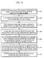
- FIG. 6is a block diagram reciting the steps of a preferred molding process.
- FIG. 6Ais an additional step in the process shown in FIG. 6 wherein the surface of the decorative layer may be coated.
- FIG. 7is a block diagram reciting an alternative molding process.
- FIG. 7Ais an additional step in the process shown in FIG. 7 wherein the surface of the decorative layer may be coated.
- FIG. 8is a block diagram reciting still another alternate molding process.
- FIG. 8Ais an additional step in the process shown in FIG. 8 wherein the surface of the decorative layer may be coated.
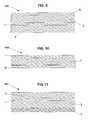
- FIGS. 9-10are enlarged cross-sectional views of appliqués or trim panels of the present invention utilizing multiple decorative layers and a clear and clear/opaque injection molded layers.
- FIGS. 11-13are enlarged cross-sectional views of appliqués or trim panels of the present invention utilizing multiple injection molded layers of clear and colored/opaque resin.
- Decorative panels in the form of appliqués and bezelsare found in many markets; automotive, appliance, marine, furniture, etc. Some of these panels also function as protective trim strips along the sides of boats and cars to prevent minor bumping damage. These panels may take on any appearance to differentiate the product which they are installed upon.
- Protective trim appliquésare often bright, reflective metal-appearing laminates or extrusions with a plastic outer layer.
- Popular inside the vehicleare “real wood” appliqués that use a preformed wood laminate which is coated with a clear plastic layer.
- a key to these wood-appearing productsis the relatively thick outer coating which yields a luxurious, expensive-appearing image.
- FIG. 1is a perspective view of the driver's side of an automobile cockpit with the main instrument panel 20 shown beneath a windshield 24 . Beneath the instrument panel, typically, there is a hidden airbag deployment system 26 whose presence is not evident on the top surface.
- Decorating the surface of the instrument panel 20are three coordinated appliqués 10 , 12 and 14 which include a wood grain pattern 16 that flows smoothly from panel to panel. Often this wood appearance flows completely across the instrument panel and along the door panels, along each side of the vehicle.
- FIG. 2A second decorative appliqué is shown in FIG. 2 where a door panel 30 which includes a grab handle 34 and armrest 36 further includes a decorative appliqué 32 , in this case having the appearance of a coarsely woven burlap type fabric, appearing to be deeply encased in a clear plastic layer.
- a door panel 30which includes a grab handle 34 and armrest 36 further includes a decorative appliqué 32 , in this case having the appearance of a coarsely woven burlap type fabric, appearing to be deeply encased in a clear plastic layer.
- Other applications for the method and construction of the present inventionare equally suitable as protective or decorative strips or panels on the outside of other vehicles, appliances, etc.
- FIG. 3The construction of the appliqué or trim panel of the present invention is shown in simplified cross-sectional view in FIG. 3 .
- the layers as shownare exaggerated in thickness for clarity of the discussion.
- the relative dimensions of the layersmay not be as depicted.
- an appliqué 10comprises a decorative layer 1 having a front side and a back side, which may include, but is not limited to, a foil, film, fabric, veneer, wood, paper, a coating or thin laminate which is covered with a layer 3 of a first plastic on its back side and has a top layer 5 overlying its front side.
- the top layer 5is preferably injection molded of a clear plastic at a thickness to provide the desired depth of image and to protect the thin decorative layer 1 .
- the backing layer 3is also injection molded and may be of nearly any plastic material and may be tinted, pigmented or otherwise decorated to enhance the appearance of the decorative layer 1 , if so desired.
- top layer 5may be tinted, pigmented or otherwise decorated to yield a specific appearance as desired.
- typical decorative materialsmay include, but, are not limited to, cloth or fabrics, metallized or painted films and foils, metal, wood grain veneers, paper, laminates formed by hydrographic or metal deposition processes, etc.
- the same modifying/repair proceduremay also be applied to the back surface of a decorative layer on which a clear layer has been molded on the front surface.
- a stainsuch as one of the KZ7 series from Allied Photochemical may be applied by spray, brush, roll, pad, dab, blot, combinations thereof or other methods commonly known in the art, when the mold halves are open and the decorative layer surface front or rear side is exposed.
- the stain or other coatingmay be in the form of a liquid, powder, paste, gel, etc., to impart a desired effect such as color, gloss, texture, pattern, repair, etc. Due to the rapid cycle times of the injection molding process, rapid drying or curing coatings are preferred, having a high solids content (for instance between about 75 and 100% solids).
- the ingredients responsible for providing the actual coatingare present in a fluid system (e.g.
- a solventat concentrations of about 75-100% wt. Curing/drying to solidify the coating may take place due to the residual heat imparted during the injection molding of the front or backing layer or by irradiation from heaters such as IR, UV, heated air, etc. Since the cycle time for molding may be desired to be as short as possible such that uptime on the molding press may be maximized, a robot with end-of-arm tooling may deliver the application and curing equipment between the mold halves after the decorative material has been over-molded on the decorative layer and the press opened. This equipment may include spray guns, pads, brushes, lamps, or heaters.
- woven or non-woven fabric or clothmay have the exposed surface treated with a coating to impart a desired visual appearance or effect, and then be covered with a protective clear or tinted coating by injection molding a layer over the exposed surface of the decorative layer.
- a key to the present inventionis an uncomplicated process for forming thin appliqués or trim panels.
- a decorative layer 1is positioned between mold halves.
- mold core 2is aligned with the mold cover 4 there is a resulting cavity space formed for a first plastic 3 to be injection molded behind the decorative layer 1 .
- Thiscauses the decorative layer 1 to conform to the shape of the mold cover 4 and for the first plastic to fill out the space between the core 2 and cover 4 .
- the core 2 and cover 4are aligned by a shear edge 6 which extends around the projected core 2 and closely interfaces with the cover 4 .
- the shear edge 6is lengthened so that an additional top layer 5 may be injected (see FIG.
- the decorative layer 1 in FIG. 4may be cut to conform to the dimensions of the space between the core 2 and cover 4 or may extend across the land area of the cover 4 and be held in place, or even cut off by the core 2 along the shear edge 6 when the core 2 and cover 4 are aligned.
- FIG. 5it is shown that the core 2 of FIG. 4 has been retracted out of the cover 4 portion of the mold set by an amount, a, which is preferably substantially equal to the thickness of the top layer 5 of the appliqué 10 . This allows the preferably clear outer layer 5 to be injected over the decorative composite formed by the decorative layer 1 and backing layer 3 .
- the preferably clear outer layer 5may comprise any of the clear, preferably light stable, plastics available in the art, including but not limited to, polycarbonate, polymethyl-methacrylate, thermoplastic urethane, polyester, copolyester alloys, cyclic olefin copolymer, poly-4-methyl-1-pentene, polysulphone, allyl diglycol carbonate, allyl ester, styrene-acrylonitrile, polystyrene and polyvinyl chloride.
- plasticsavailable in the art, including but not limited to, polycarbonate, polymethyl-methacrylate, thermoplastic urethane, polyester, copolyester alloys, cyclic olefin copolymer, poly-4-methyl-1-pentene, polysulphone, allyl diglycol carbonate, allyl ester, styrene-acrylonitrile, polystyrene and polyvinyl chloride.
- the clear plastic outer layer 5comprises a copolymer and more particularly a cyclic olefin copolymer, such as TOPAS® 6015S-04 from Ticona, or a co-polyester alloy, such as OPTIMUM® 800 Grade from Engineered Plastics Corporation.
- the appliqué 10 as formed by the method of the present inventionmay be of any thickness suitable for the application for which the appliqué is intended, typically from about 1.0 mm. to about 5.0 mm. with a clear outer layer 5 typically of about 0.5 mm. to about 1.0 mm. in thickness, depending on the molding properties of the clear resin used for the outer layer 5 .
- Unique to the specific construction and method of the present inventionis the ability to mold the appliqué 10 in a single mold set (core 2 , cover 4 ) without having to exchange mold halves to accommodate the outer layer 5 . Also unique is the ability to produce very thin appliqués, of about 1 mm. in thickness by a single injection mold set.
- the process of a preferred embodiment of the present inventionpreferably comprises (see FIG. 6 ) the steps of providing a mold core and cover, which cooperate to form a cavity space, in an injection molding machine (Block 200 ); positioning a, preferably thin, decorative layer 1 across the mold cover 4 which includes a contoured surface (Block 202 ); aligning the mold core 2 , having a contoured surface which mates with, but is spaced from, the contoured surface of the mold cover, with the mold cover 4 to form a first injection volume (Block 204 ); injecting a first plastic as a backing layer 3 on to the back side of the decorative layer 1 and into the injection volume to conform the decorative layer 1 to the cover portion and form a decorative composite (Block 206 ); solidifying the first plastic material and retracting the core 2 along with the composite formed by the decorative layer 1 and first plastic 3 (Block 208 ) along lengthened shear edges which allow the tooling to remain substantially sealed; injecting a second plastic onto the front surface of the decorative layer 1 to form
- the inventionmay also be accomplished by injecting the clear layer on the front side of the decorative layer first (at Block 206 ), retracting the mold core away from the decorative composite, and injecting the backing layer (at Block 210 ).
- an appliqué′may be similarly formed by co-injecting the two plastic materials on to both the front and back sides of the decorative at substantially the same time and allowing the injection pressure to open the mold halves to form the finished appliqué′, or optionally to fill the cavity space between the mold halves without moving the mold halves.
- this stepmay take place between Block 208 and Block 210 in FIG. 6 .
- the mold halvesmay be open, briefly, and may allow manual or automated application of on or more coatings to the exposed (front) surface of the decorative material.
- this additional stepidentified as Block 209 and shown in FIG. 6A , would occur when the mold is open and may entail applying a coating to the exposed surface of the decorative material, followed by drying or curing of the coating.
- Additional layers of decorative material and clear and colored/opaque plasticmay be added to the construction as described in FIG. 6 by replicating the steps as shown (for instance, retracting the mold core, draping an additional decorative layer across a cavity space so formed and injecting a layer of plastic behind the film, or injecting one or more layers against the front side or back side of the appliqué formed at 212 in FIG. 6 .
- the positioning of layer 1 referenced abovemay be by draping the material across one of the open mold halves, as recited in FIGS. 6 , 7 and 8 .
- the decorative layer 1may be placed within the confines of the mold cavity and held in place by magnets, pins, friction, vacuum, etc.
- Appliqués of the present inventionmay also preferably include fastening means for attachment to other surfaces, including but not limited to, hook and loop, molded bosses which interact with Palnuts, molded Xmas tree projections, and sections which snap-fit into adjacent or mounting surfaces.
- the fastening featuresmay include dielocks, undercuts and various other female features known in the art.
- An alternate method of forming the appliqué of the present inventioninvolves a 2 stage process as described in FIG. 7 .
- a first mold core 2 having a contoured projecting portion and a first mold cover 4 having a similarly contoured, preferably recessed, portion spaced from the coreare aligned to form an injection volume for forming a decorative composite layer (Block 300 ).
- a decorative layer 1is positioned between the contoured portions of the mold cover 4 and mold core 2 (Block 302 ), the mold core 2 and cover 4 are aligned and closed (Block 304 ) and a first plastic material injected on to the back side of the decorative layer 1 to form a backing layer 3 (Block 306 ).
- the decorative composite formed of decorative layer 1 and backing layer 3is removed from the molds and placed into a second set of molds comprising core 2 A and cover 4 A (Block 308 ).
- the contoured projecting portion of the core 2 Amay be slightly smaller in dimension than that of core 2 to accommodate any shrinkage of the backing layer.
- Core 2 A and cover 4 Acooperate to define a second injection volume between the mold halves which is greater than the volume of the decorative composite (Block 310 ).
- a second plastic materialpreferably clear, is injected into the space between the mold cover 4 A and the composite layer outer surface to form a protective outer layer 5 (Block 312 ).
- the appliqué 10may be removed from the mold 2 A, 4 A and trimmed (Block 314 ).
- the outer layer 5may be injected against the decorative layer first (at Block 306 ) and subsequently the backing layer may be injected in the second tool set (at Block 312 ).
- this stepmay take place between Block 308 and Block 310 in FIG. 7 .
- the mold halvesmay be open, briefly, and may allow manual or automated application of on or more coatings to the exposed surface of the decorative material.
- this additional stepidentified as Block 309 and shown in FIG. 7A , would occur when the mold is open and may entail applying a coating to the exposed surface of the decorative material, followed by drying or curing of the coating.
- Additional layers of decorative material, and clear and colored/opaque plasticmay be added to the construction as described in FIG. 7 by replicating the steps as shown (for instance, moving the decorative composite to a second mold set, draping an additional decorative layer across the cavity space so formed and injecting a layer of plastic behind the film, or injecting one or more layers against the front side or back side of the appliqué formed at 312 in FIG. 7 .
- a third method for alternatively forming an appliqué of the present inventionis disclosed in U.S. Pat. No. 6,468,458, commonly assigned to the assignee of the present invention and included herein by reference.
- This methodincludes a two part mold system wherein one of the mold parts is moveable (Block 400 ) and includes mold covers having contoured, preferably, cavity portions and the other of the mold parts is stationary and may include a mold core having a similar contoured surface spaced from the cover.
- the mold covers and corecooperate to form different injection volumes (Block 402 , Block 404 ) to accommodate injecting a first plastic behind a decorative layer using a first mold cover and first mold core (Block 406 ), and then aligning a second mold cover which provides a larger cavity area with the first mold core (Block 410 ) including the decorative composite to accommodate the subsequent injection of an outer layer (Block 410 ).
- the finished appliqué′is removed (Block 412 ).
- the moveable mold partsallow rotation of the mold covers, in this case, to align with the mold core to allow overshooting of the clear layer. This is described schematically in FIG. 8 .
- Additional layers of decorative material and clear and colored/opaque plasticmay be added to the construction as described in FIG. 8 by replicating the steps as shown (for instance, rotating another cavity into position, draping an additional decorative layer across the cavity space so formed and injecting a layer of plastic behind the film, or injecting one or more layers against the front side or back side of the appliqué formed at 412 in FIG. 8 .
- this stepmay take place between Block 408 and Block 410 in FIG. 8 .
- the mold halvesmay be open, briefly, and may allow manual or automated application of on or more coatings to the exposed surface of the decorative material.
- this additional stepidentified as Block 409 and shown in FIG. 8A , would occur when the mold is open and may entail applying a coating to the exposed surface of the decorative material, followed by drying or curing of the coating.
- the outer layermay be formed first in the cavity portion of a mold cover and subsequently that cover containing the decorative composite comprising the decorative layer and outer layer may be aligned with a second mold core having a smaller contoured profile to allow the backing layer to be formed between the composite layer and the smaller contoured profile.
- either of the mold parts, cores or coversmay be attached to either of the movable or stationary mold platens.
- the moveable mold partis carried on a rotary platen that allows the moveable mold part to rotate and align with the stationary mold parts.
- the moveable mold partcarries the composite laminate from station to station and the stationary mold part has a profile that allows space for the injection of the subsequent layer to form the finished appliqué.
- multiple decorative layersmay be included in the construction of the appliqué to provide a distinguishing appearance.
- the layers as shownare exaggerated in thickness for clarity of the discussion. The relative dimensions of the layers may not be as depicted.
- One or more of the decorative layers 1 , 1 amay include portions which are transparent allowing a colored or opaque backing layer to show through the layered construction.
- FIG. 9illustrates a combination of a first decorative layer 1 backed by an injection molded layer of colored or opaque plastic 3 forming a first decorative composite which may then be inserted into a second mold set in which a second decorative layer 1 a has been placed. Subsequently, a clear plastic may be injected between the film layers 1 , 1 a to form a clear layer 3 and a finished appliqué 10 A.
- FIG. 10illustrates another process involving multiple decorative layers wherein a first decorative layer 1 and a second decorative layer 1 a may be placed into a mold set, such as described in FIG. 6 , and a clear resin 5 injected between the decorative layers to form an appliqué 10 B.
- the second decorative layer 1 amay be a bilaminate, such as manufactured by Avery Dennison Corporation comprising two carrier films, one of which has a pattern printed thereupon wherein the graphics lie between the films.
- the first decorative layer 1may include at least some transparent portions, through which the graphics can be seen.
- the graphicsdue to the relative thickness of the clear layer 5 , may appear to be floating in the clear layer, providing an exceptional depth of image.
- the appliqués formed and configured as described herein having portions which are transparentmay be provided with backlighting to further enhance their appearance.
- first and second decorative layersmay be different in one or more of the following characteristics: type of decorative pattern, material (polymer type), color, areas of transparency relative to areas of opacity, thickness, hardness, strength (e.g. tensile strength).
- each decorative layermay itself be composed of several layers, each with graphics or printing thereon, to provide an overall decorative appearance.
- any of the processes disclosed in FIGS. 6-8may then be used to provide the appliqué construction of FIG. 9 by using the appliqué 10 B as the decorative composite of FIGS. 6-8 and injecting a clear 5 or colored/opaque plastic 3 against one or both of the decorative films 1 , 1 a .
- the second decorative layermay block portions of the light being projected through the appliqué.
- typical decorative materialsmay include, but, are not limited to, cloth or fabrics, metallized or painted films and foils, metal, wood grain veneers, paper, laminates formed by hydrographic or metal deposition processes.
- a coatingmay be applied to the exposed surface of any of the decorative layers 1 , 1 a when the mold set is open to further decorate or enhance the appearance of the resultant appliqué 10 A, 10 B.
- FIGS. 11-13Additional appliqué constructions formed by multi-shot injection molding using the processes disclosed herein are illustrated in FIGS. 11-13 .
- the layers as shownare exaggerated in thickness for clarity of the discussion. The relative dimensions of the layers may not be as depicted.
- FIG. 11is a cross-sectional view of an appliqué 10 C wherein a first decorative layer appears to be floating over a second decorative layer, in this case a coating of paint.
- a first decorative layer 1is molded with a clear layer 5 on both the front side and back side, followed by coating one of the exposed surfaces of the clear layer 5 with a colored paint 7 .
- FIG. 12is a cross-sectional view of an appliqué 10 D wherein a first decorative layer 1 is backed by an injection molded clear layer 5 which is in turn backed with an opaque or colored injection molded layer 3 .
- the colored layermay include but not be limited to, for instance, polycarbonate, acrylonitrile-butadiene-styrene and combinations thereof and have a thickness in the range of about 1.5-2.5 mm. This construction provides a visual effect that whatever is printed on the decorative film may appear to be suspended deep within the clear layer and on the surface of the opaque or colored layer.
- the colored layermay be white, and the graphics of the decorative layer may appear to be floating on the surface of the white substrate.
- the decorative film layermay have graphics printed on or within the layer as well as transparent areas which may allow one to see the colored layer through the film and clear layer.
- FIG. 13is a cross-sectional view of an appliqué 10 E wherein the paint layer 7 in FIG. 11 is replaced with an injection molded colored backing layer 3 of FIG. 12 .
- the backing layer 3may include integral or insert-molded fastening (not shown) means as described above.
- the decorative layer 1 for any of the embodiments shown in the figuresmay include portions which are transparent allowing a colored or opaque backing layer to show through the layered construction.
- a thin wood veneer from Kimpara & Co., LTD. of Japan about 0.5 mm. in thicknesswas placed between the core and cover of an injection mold for an instrument panel appliqué such as shown in FIG. 1 .
- a first plastic material, 5135 polypropylene from Huntsman, LLCwas injected behind the wood veneer layer to conform the layer to the shape of a contoured cavity area in the mold cover and fill out the cavity space to form a backing layer.
- the core portion of the mold setwas retracted 1.5 mm with the backing layer and decorative layer composite remaining tightly affixed to the mold core.
- the resulting cavity space formed by the retraction of the core from the coverwas filled with a second polymer material, V825 poly(methylmethacrylate) from the Atoglas Division of Atofina, the chemical branch of TOTAL.
- a wood grained molding having a luxurious appearancewas obtained.
- a section of coarsely woven fabric, a circular knit, WF0023 from Collins and Aikman Products Co.was positioned between the mold core and mold cover.
- TOPAS® 6015S-04a cyclic olefin copolymer from Ticona
- Ticonaa cyclic olefin copolymer from Ticona
- the mold corewas retracted along with the combined fabric and backing layer and a second layer of cyclic olefin copolymer was injected into the open space, thus forming a protective top layer on the fabric.
- a unique appearing appliquéwas formed having an open weave fabric appearance buried deep in a clear layer.
- the filmcomprised an acrylic laminate having a pattern printed on one of the layers, the pattern covered by a second layer of acrylic such that over-molding would not disturb the appearance of the graphic pattern.
- a clear plastic materialsuch as HFI-7 from Atoglas was injected on the front side of the decorative film to conform the film to the shape of the mold and fill out the space between the cover and core of the injection mold.
- This layerwas about 1.5 mm. in thickness.
- the mold corewas retracted to yield a cavity space between the back side of the decorative film and the mold core and that cavity space filled with a second layer of clear resin about 2.5 mm. in thickness.
- This compositewas removed from the injection mold and a layer of paint applied to at least a portion of the backside of the second clear layer.
- This composite constructionyielded an appliqué having graphics visible from a first surface, the graphics appearing to be located deep in the second clear layer.
- the transparent portions of the decorative filmprovided an opportunity for backlighting while the printed portions and the paint layer covered any attachment features of the appliqué.
- a thin walled decorative appliquéwhich may function as a decorative or protective surface or edging may be produced using an efficient molding process whereby a thin decorative layer is shaped by injecting a first plastic material, preferably as a backing layer, behind the decorative layer, and subsequently a second plastic material, preferably a clear polymer, is injected on the opposite side, preferably the front side of the decorative layer, to form an appliqué.
- a first plastic materialpreferably as a backing layer
- a second plastic materialpreferably a clear polymer
- the appliqué formed by these methodsis distinguished by a wide variety of thin decorative materials that may comprise the decorative layer, by additives in the form of tints, pigments and flakes that may be used in the injection molded layers to emphasize the decorative layer, by the use of, preferably, a clear polymer as the outer layer of the appliqué which provides a unique depth of image which further emphasizes the appearance of the underlying decorative layer, and by the forming of the thin decorative layer by the injection of the first plastic material.
- a clear polymeras the outer layer of the appliqué which provides a unique depth of image which further emphasizes the appearance of the underlying decorative layer
- the forming of the thin decorative layerby the injection of the first plastic material.
Landscapes
- Engineering & Computer Science (AREA)
- Life Sciences & Earth Sciences (AREA)
- Wood Science & Technology (AREA)
- Textile Engineering (AREA)
- Manufacturing & Machinery (AREA)
- Mechanical Engineering (AREA)
- Injection Moulding Of Plastics Or The Like (AREA)
Abstract
Description
Claims (12)
Priority Applications (2)
| Application Number | Priority Date | Filing Date | Title |
|---|---|---|---|
| US12/352,487US7981342B2 (en) | 2003-12-31 | 2009-01-12 | In-mold lamination of decorative products |
| US13/186,231US20110272851A1 (en) | 2003-12-31 | 2011-07-19 | In-Mold Lamination Of Decorative Products |
Applications Claiming Priority (5)
| Application Number | Priority Date | Filing Date | Title |
|---|---|---|---|
| US53363203P | 2003-12-31 | 2003-12-31 | |
| PCT/US2005/000170WO2005070647A1 (en) | 2003-12-31 | 2005-01-03 | In mold lamination of decorative products |
| US11/428,107US7674414B2 (en) | 2003-12-31 | 2006-06-30 | In mold lamination of decorative products |
| US11/532,825US20070194487A1 (en) | 2003-12-31 | 2006-09-18 | In-Mold Lamination Of Decorative Products |
| US12/352,487US7981342B2 (en) | 2003-12-31 | 2009-01-12 | In-mold lamination of decorative products |
Related Parent Applications (1)
| Application Number | Title | Priority Date | Filing Date |
|---|---|---|---|
| US11/532,825Continuation-In-PartUS20070194487A1 (en) | 2003-12-31 | 2006-09-18 | In-Mold Lamination Of Decorative Products |
Related Child Applications (1)
| Application Number | Title | Priority Date | Filing Date |
|---|---|---|---|
| US13/186,231ContinuationUS20110272851A1 (en) | 2003-12-31 | 2011-07-19 | In-Mold Lamination Of Decorative Products |
Publications (2)
| Publication Number | Publication Date |
|---|---|
| US20090174121A1 US20090174121A1 (en) | 2009-07-09 |
| US7981342B2true US7981342B2 (en) | 2011-07-19 |
Family
ID=40843929
Family Applications (2)
| Application Number | Title | Priority Date | Filing Date |
|---|---|---|---|
| US12/352,487Expired - Fee RelatedUS7981342B2 (en) | 2003-12-31 | 2009-01-12 | In-mold lamination of decorative products |
| US13/186,231AbandonedUS20110272851A1 (en) | 2003-12-31 | 2011-07-19 | In-Mold Lamination Of Decorative Products |
Family Applications After (1)
| Application Number | Title | Priority Date | Filing Date |
|---|---|---|---|
| US13/186,231AbandonedUS20110272851A1 (en) | 2003-12-31 | 2011-07-19 | In-Mold Lamination Of Decorative Products |
Country Status (1)
| Country | Link |
|---|---|
| US (2) | US7981342B2 (en) |
Cited By (7)
| Publication number | Priority date | Publication date | Assignee | Title |
|---|---|---|---|---|
| US20060138699A1 (en)* | 2004-12-24 | 2006-06-29 | Bayer Materialscience Ag | Process for the production of a molded article |
| US20100167026A1 (en)* | 2007-01-17 | 2010-07-01 | Hayes Marc A | Decorative products having depth of image |
| US20130119581A1 (en)* | 2010-07-07 | 2013-05-16 | Nbhx Trim Gmbh | Method for producing a decorative part |
| US20170361514A1 (en)* | 2016-06-15 | 2017-12-21 | Hyundai Motor Company | Method of coating surface of interior component for vehicle |
| US10406735B2 (en) | 2016-02-24 | 2019-09-10 | Dura Operating, Llc | Injection molded part with insert film |
| US10562446B2 (en) | 2015-03-23 | 2020-02-18 | International Automotive Components Group Gmbh | Interior trim element for a motor vehicle |
| US20210187794A1 (en)* | 2017-04-24 | 2021-06-24 | Nike, Inc. | Transparent tooling for uv radiation curable rubber |
Families Citing this family (32)
| Publication number | Priority date | Publication date | Assignee | Title |
|---|---|---|---|---|
| US8092733B2 (en)* | 2003-12-31 | 2012-01-10 | International Automotive Components Group North America, Inc. | In mold lamination of decorative products |
| JP2007517686A (en)* | 2003-12-31 | 2007-07-05 | コリンズ・アンド・アイクマン・プロダクツ・コーポレーション | In-mold lamination of decorative products |
| US8083979B2 (en)* | 2003-12-31 | 2011-12-27 | International Automotive Components Group North America, Inc. | In mold lamination of decorative products |
| US7976757B2 (en)* | 2009-08-27 | 2011-07-12 | Ju Teng International Holdings Limited | Mold decoration process |
| EP2298528A1 (en)* | 2009-09-16 | 2011-03-23 | Quin GmbH | Decorative part and method for manufacturing same |
| CH703208A1 (en)* | 2010-05-19 | 2011-11-30 | Kistler Holding Ag | Method for the detection of insert objects in an injection part. |
| EP2651615A4 (en)* | 2010-12-15 | 2015-04-08 | Srg Global Inc | Methods of multi-shot injection molding and durable polymeric assemblies made therefrom |
| JP5726551B2 (en)* | 2011-01-28 | 2015-06-03 | セーレン株式会社 | Decorative resin molded product and manufacturing method thereof |
| US9062386B2 (en) | 2011-03-01 | 2015-06-23 | Srg Global, Inc. | Methods of multi-shot injection molding and metal-plated polymeric articles made therefrom |
| US9228082B2 (en)* | 2012-03-28 | 2016-01-05 | Sabic Global Technologies B.V. | Polyetherimide polycarbonate blends |
| WO2013170912A1 (en)* | 2012-05-14 | 2013-11-21 | Gerhardi Kunststofftechnik Gmbh | Composite component made of plastic |
| US9539749B2 (en) | 2012-05-15 | 2017-01-10 | Blackberry Limited | Formable inserts and related methods |
| FR2991910B1 (en)* | 2012-06-14 | 2014-08-08 | Faurecia Interieur Ind | PACKING ELEMENT AND METHOD OF MANUFACTURING THE SAME |
| DE102012211951A1 (en) | 2012-07-09 | 2014-01-09 | Wiegand Gmbh | Decorative part for motor vehicles and method for its production |
| DE102012111187A1 (en)* | 2012-11-20 | 2014-05-22 | Marko Marquardt | Translucent molding |
| DE102013214103A1 (en)* | 2013-07-18 | 2015-01-22 | Bayerische Motoren Werke Aktiengesellschaft | sandwich component |
| EP2848404B1 (en)* | 2013-09-13 | 2017-11-29 | Faurecia Innenraum Systeme GmbH | Roller shutter and storage compartment comprising said roller shutter |
| CN104637713A (en)* | 2013-11-06 | 2015-05-20 | 致伸科技股份有限公司 | Keyboard device and method for forming keys of keyboard device |
| US10495071B1 (en)* | 2014-12-09 | 2019-12-03 | Robert E. Jenkins | Rotational gravitational torque-generating system and method |
| EP3100915B2 (en) | 2015-06-03 | 2022-09-28 | WEIDPLAS GmbH | Component |
| EP3482279A4 (en) | 2016-07-11 | 2020-01-29 | Shanghai Yanfeng Jinqiao Automotive Trim Systems Co. Ltd | INTERIOR COMPONENT |
| US10377068B2 (en)* | 2016-09-23 | 2019-08-13 | Inteva Products, Llc | Method and apparatus for non-woven trim panels |
| JP6576899B2 (en)* | 2016-10-21 | 2019-09-18 | Nissha株式会社 | Decorative layer / resin laminated structure housing and manufacturing apparatus thereof |
| WO2018129071A1 (en) | 2017-01-06 | 2018-07-12 | Shanghai Yanfeng Jinqiao Automotive Trim Systems Co. Ltd. | Vehicle interior component |
| DE102017209457A1 (en)* | 2017-06-02 | 2018-12-06 | Faurecia Innenraum Systeme Gmbh | Method and tool for producing a vehicle interior trim part and vehicle interior trim part |
| CN107176113A (en)* | 2017-06-21 | 2017-09-19 | 上海延锋金桥汽车饰件系统有限公司 | One kind decoration panel |
| WO2019165441A1 (en) | 2018-02-26 | 2019-08-29 | Shanghai Yanfeng Jinqiao Automotive Trim Systems Co. Ltd. | Vehicle interior component |
| CN114245887B (en) | 2019-07-15 | 2024-11-29 | 上海延锋金桥汽车饰件系统有限公司 | Vehicle interior component |
| DE102019130284A1 (en)* | 2019-11-11 | 2021-05-12 | Bayerische Motoren Werke Aktiengesellschaft | Method for producing a curved substrate wafer with a hologram, resulting substrate wafer with hologram and a wafer composite containing this, in particular a vehicle window |
| US11560103B2 (en)* | 2020-02-18 | 2023-01-24 | GM Global Technology Operations LLC | Component with integrated sensor chip |
| DE102020134484A1 (en)* | 2020-12-21 | 2022-06-23 | Preh Gmbh | Manufacturing process for an optically improved plastic composite cover and associated arrangement of the plastic composite cover and a carrier |
| EP4112290A1 (en) | 2021-06-30 | 2023-01-04 | Volvo Car Corporation | Seamless integration of illumination into interior trim panels with decorative surface materials |
Citations (73)
| Publication number | Priority date | Publication date | Assignee | Title |
|---|---|---|---|---|
| US3246066A (en) | 1963-04-17 | 1966-04-12 | Jules P Gits | Method of making three dimensional molded articles |
| US3654062A (en) | 1970-09-28 | 1972-04-04 | Standard Products Co | Injection molded decorative plaques |
| US3873656A (en) | 1967-12-15 | 1975-03-25 | Ici Ltd | Production of laminar articles |
| US4010057A (en) | 1974-08-12 | 1977-03-01 | Kabushiki Kaisha Kobayashi | Printing apparatus |
| US4349592A (en) | 1980-07-17 | 1982-09-14 | The Standard Products Company | Thermoplastic elastomer molding |
| US4396680A (en) | 1981-03-04 | 1983-08-02 | E. I. Du Pont De Nemours And Co. | Substrate coated with crater resistant acrylic enamel |
| US4444711A (en) | 1981-12-21 | 1984-04-24 | Husky Injection Molding Systems Ltd. | Method of operating a two-shot injection-molding machine |
| US4460534A (en) | 1982-09-07 | 1984-07-17 | International Business Machines Corporation | Two-shot injection molding |
| US4681811A (en) | 1985-08-19 | 1987-07-21 | Ppg Industries, Inc. | Color plus clear coatings employing polyepoxides and polyacid curing agents in the clear coat |
| US4822828A (en) | 1987-11-23 | 1989-04-18 | Hoechst Celanese Corporation | Radiation curable coating composition based on a silica/vinyl-functional silanol dispersion |
| US4849145A (en) | 1985-04-15 | 1989-07-18 | Hermann Hirsch | Process for the production of material having at least two layers |
| US4917927A (en) | 1988-05-26 | 1990-04-17 | Katsutoshi Sakaitani | Synthetic resin moldings and method for the manufacture thereof |
| JPH0330922A (en) | 1989-06-28 | 1991-02-08 | Yamaha Corp | Composite component of wooden overlay sheet and synthetic resin |
| US5009821A (en) | 1989-02-23 | 1991-04-23 | Libbey-Owens-Ford Co. | Molding method for eliminating fiber readout |
| US5030406A (en) | 1989-08-14 | 1991-07-09 | Sorensen Jens Ole | Sequentially injected multi-component shuttle-stack-molding |
| US5049345A (en) | 1988-11-01 | 1991-09-17 | Continental Pet Technologies, Inc. | Method of forming a multi-layer preform |
| US5131702A (en)* | 1988-07-25 | 1992-07-21 | Ardyne, Inc. | Automotive bumper and its manufacturing process |
| JPH05131487A (en) | 1991-09-06 | 1993-05-28 | Yamaha Corp | Manufacture of composite formed article |
| US5225264A (en) | 1989-12-07 | 1993-07-06 | Yamaha Corporation | Composite molded article |
| US5320869A (en) | 1992-12-04 | 1994-06-14 | Davidson Textron Inc. | Method for producing high gloss bright colored plastic articles |
| US5350608A (en) | 1993-04-13 | 1994-09-27 | The Standard Products Company | Decorative trim with one-piece plastic cover |
| US5352532A (en) | 1989-08-03 | 1994-10-04 | Glass Alternatives Corp. | Panel and method of making same |
| US5432666A (en) | 1993-01-22 | 1995-07-11 | Illinois Superconductor Corporation | Self-restoring fault current limiter utilizing high temperature superconductor components |
| JPH07186165A (en) | 1993-12-28 | 1995-07-25 | Kasai Kogyo Co Ltd | Preparation of interior automotive trim |
| DE4301444C2 (en) | 1993-01-20 | 1995-08-31 | Pelz Ernst Empe Werke | Method for producing a lining part and in particular a lining part produced according to it |
| US5525179A (en) | 1994-07-18 | 1996-06-11 | Empe-Werke Ernst Pelz Gmbh & Co. Kg | Method of manufacturing a lining part |
| DE4124297C2 (en) | 1991-07-22 | 1996-07-11 | Pelz Ernst Empe Werke | Lining part for motor vehicles |
| US5641547A (en) | 1995-09-13 | 1997-06-24 | Plastic Trim, Inc. | Injection molded trim strip and method for making same |
| US5651998A (en)* | 1994-06-06 | 1997-07-29 | Husky Injection Molding Systems Ltd. | Injection molding system for forming a multilayered molded article |
| DE19717740A1 (en) | 1997-04-26 | 1998-11-05 | Schoenberg & Cerny Gmbh | Plastic molded body with integrated optoelectronic lighting element |
| US5853901A (en) | 1996-12-19 | 1998-12-29 | Cessna; Frank L. | Lightweight decorative paper products for pressure laminates and method for forming the same |
| US5863479A (en) | 1991-09-06 | 1999-01-26 | Yamaha Corporation | Production method for a composite molded article |
| US6102536A (en) | 1996-01-26 | 2000-08-15 | Tetra Laval Holdings & Finance, Sa | Method and apparatus for printing images on a web of packaging material |
| US6117384A (en) | 1997-11-06 | 2000-09-12 | General Electric Co. | In-mold decorating process |
| WO2001045860A2 (en) | 1999-12-22 | 2001-06-28 | Erwin Behr Automotive Gmbh | Method and device for coating the surface of an interior component for motor vehicles |
| DE10022019A1 (en) | 2000-05-05 | 2001-11-08 | Huber Signalbau Ag | Manufacturing optical diffuser disc for signaling equipment, locating partially-transparent film in casting mold and injecting plastic bonding to it |
| US20020007898A1 (en) | 2000-03-28 | 2002-01-24 | Joseph Spica | Engineered wood and methods therefor |
| US20020100387A1 (en) | 2001-01-31 | 2002-08-01 | Churchwell Richard N. | Method of decorating a plastic part and associated business model |
| US6444319B1 (en) | 1998-04-29 | 2002-09-03 | Erwin Behr Gmbh & Co. Kg | Method for the surface coating of an interior fitting and interior fitting produced according thereto |
| US6444317B1 (en) | 1998-08-06 | 2002-09-03 | Kansai Paint Co., Ltd. | Decorative film for use in plastics molding, process for preparing the same and injection-molded part by use of the same |
| US6468458B1 (en)* | 1998-10-23 | 2002-10-22 | Textron Automotive Company Inc, | Method for forming a composite product |
| US20020157772A1 (en) | 1995-06-07 | 2002-10-31 | Avery Dennison Corporation | Extrusion coating process for making protective and decorative films |
| US20030001311A1 (en) | 1995-07-07 | 2003-01-02 | Continental Pet Technologies, Inc. | Sleeve molding |
| US20030041962A1 (en) | 2001-09-05 | 2003-03-06 | John R. Johnson | Digitally printed products and process |
| US20030162045A1 (en) | 2002-02-25 | 2003-08-28 | Erwin Behr Automotive Gmbh | Method of producing an interior fitment for vehicles, and interior fitment produced accordingly |
| US6623677B1 (en) | 2000-07-21 | 2003-09-23 | Bayer Corporation | Decorated article made by film insert molding |
| US20040101668A1 (en) | 2001-11-06 | 2004-05-27 | Northern Engraving Corporation | Method of manufacturing multiple levels of automobile trim |
| US20040110895A1 (en) | 1999-07-30 | 2004-06-10 | Ppg Industries Ohio, Inc. | Flexible coating compositions having improved scratch resistance, coated substrates and methods related thereto |
| US20040123942A1 (en) | 1987-03-27 | 2004-07-01 | Spain Patrick L. | Dry paint transfer process for making deep-draw high doi automotive body panels |
| DE202004019298U1 (en) | 2004-12-14 | 2005-02-17 | Quin Gmbh | Vehicle steering wheel has a ring around the metal support structure, with a decorative layer over an injection molded carrier shell of a filled and heat-resistant plastics |
| US20050098257A1 (en) | 2002-07-08 | 2005-05-12 | Bauer John C. | Method and system for producing an interior trim component |
| WO2005070647A1 (en) | 2003-12-31 | 2005-08-04 | Collins & Aikman Products Co. | In mold lamination of decorative products |
| DE202004001133U1 (en) | 2004-01-27 | 2005-08-04 | Quin Gmbh | Molded component e.g. for vehicle steering wheel has transparent thermoplastic layer on decorated layer, welded to both bowls |
| EP1147872B1 (en) | 1995-07-07 | 2005-09-14 | Graham Packaging PET Technologies Inc. | Method for molding multi-layer plastic articles |
| US20050249923A1 (en) | 2004-05-05 | 2005-11-10 | Reichwein David P | Digitally printed molding and trim |
| EP1604797A1 (en) | 2004-06-10 | 2005-12-14 | Key Safety Systems, Inc. | Decorative elements for motor vehicle interiors, process and molds for their production |
| DE102004035758A1 (en) | 2004-07-23 | 2006-03-16 | Quin Gmbh | Production of a decorated blank made from a decorated material comprises placing the decorated material between two mold halves of a molding device and placing the mold halves together in a closing direction |
| DE102004035759A1 (en) | 2004-07-23 | 2006-03-16 | Quin Gmbh | Plastic coated decorative component manufacture involves injecting transparent coating onto front side of decorative material and moving core to form second cavity into which supporting plastic is injected |
| US20060216469A1 (en) | 2000-12-29 | 2006-09-28 | Kenichi Hashizume | Method for manufacturing a resin injection molded article with a reinforcing or decorative core |
| US20070001558A1 (en) | 2005-06-30 | 2007-01-04 | Bush Industries, Inc. | Digitally printed furniture and methods for manufacture thereof |
| DE102005033051A1 (en) | 2005-07-15 | 2007-01-25 | Quin Gmbh | Decorative motor vehicle component manufacture involves inserting expandable bellows into opening in component to press overlapping edge of cover material into opening and onto inner wall |
| DE202005021105U1 (en) | 2005-07-15 | 2007-02-22 | Quin Gmbh | Decorative component for a motor vehicle comprises a decorative covering with an edge region that extends through an opening in a support and is bonded flat onto the inner wall of the opening |
| US20070054116A1 (en) | 2003-12-31 | 2007-03-08 | Neitzke Mark K | In-Mold Lamination Of A Decorative Product To A Primary Substrate |
| US7227619B2 (en) | 2004-04-01 | 2007-06-05 | Asml Netherlands B.V. | Lithographic apparatus and device manufacturing method |
| US7250216B2 (en) | 2002-06-19 | 2007-07-31 | Crane Composites, Inc. | Lighter-weight reinforced decorative composite material |
| US20070194487A1 (en)* | 2003-12-31 | 2007-08-23 | Collins & Aikman Products Co. | In-Mold Lamination Of Decorative Products |
| EP1839952A2 (en) | 2006-03-28 | 2007-10-03 | Delphi Korea Corporation | Emblem of automobile part and method of manufacturing the same |
| US20080034508A1 (en) | 2006-07-05 | 2008-02-14 | Abbott Michael D | Textile finishing agents and methods of digitally printing textiles |
| US20080044677A1 (en) | 2006-08-15 | 2008-02-21 | Panolam Industries International, Inc. | Multi-colored decorative laminate |
| US7396500B2 (en) | 2002-07-29 | 2008-07-08 | Dow Technologies Inc. | Molded parts with metal or wood surface areas and processes for their production |
| WO2008088841A2 (en) | 2007-01-17 | 2008-07-24 | Collins & Aikman Products Co. | Decorative products having depth of image |
| WO2009012602A1 (en) | 2007-07-20 | 2009-01-29 | Celfa Ag | Method for the production of decorated plastic parts |
| US20100080970A1 (en)* | 2003-12-31 | 2010-04-01 | International Automotive Components Group North America, Inc. | In mold lamination of decorative products |
Family Cites Families (3)
| Publication number | Priority date | Publication date | Assignee | Title |
|---|---|---|---|---|
| US5209956A (en)* | 1990-06-18 | 1993-05-11 | D. Swarovski & Co. | Decorative panel and a method of producing it |
| US6488458B2 (en)* | 1996-02-23 | 2002-12-03 | Hitachi, Ltd. | Taper implant and a screw-fastening structure using a taper implant with female threads |
| JPH09286039A (en)* | 1996-04-22 | 1997-11-04 | Komatsu Ltd | Plate-shaped composite and its manufacturing method |
- 2009
- 2009-01-12USUS12/352,487patent/US7981342B2/ennot_activeExpired - Fee Related
- 2011
- 2011-07-19USUS13/186,231patent/US20110272851A1/ennot_activeAbandoned
Patent Citations (95)
| Publication number | Priority date | Publication date | Assignee | Title |
|---|---|---|---|---|
| US3246066A (en) | 1963-04-17 | 1966-04-12 | Jules P Gits | Method of making three dimensional molded articles |
| US3873656A (en) | 1967-12-15 | 1975-03-25 | Ici Ltd | Production of laminar articles |
| US3654062A (en) | 1970-09-28 | 1972-04-04 | Standard Products Co | Injection molded decorative plaques |
| US4010057A (en) | 1974-08-12 | 1977-03-01 | Kabushiki Kaisha Kobayashi | Printing apparatus |
| US4349592A (en) | 1980-07-17 | 1982-09-14 | The Standard Products Company | Thermoplastic elastomer molding |
| US4396680A (en) | 1981-03-04 | 1983-08-02 | E. I. Du Pont De Nemours And Co. | Substrate coated with crater resistant acrylic enamel |
| US4444711A (en) | 1981-12-21 | 1984-04-24 | Husky Injection Molding Systems Ltd. | Method of operating a two-shot injection-molding machine |
| US4460534A (en) | 1982-09-07 | 1984-07-17 | International Business Machines Corporation | Two-shot injection molding |
| US4849145A (en) | 1985-04-15 | 1989-07-18 | Hermann Hirsch | Process for the production of material having at least two layers |
| US4681811A (en) | 1985-08-19 | 1987-07-21 | Ppg Industries, Inc. | Color plus clear coatings employing polyepoxides and polyacid curing agents in the clear coat |
| US20040123942A1 (en) | 1987-03-27 | 2004-07-01 | Spain Patrick L. | Dry paint transfer process for making deep-draw high doi automotive body panels |
| US4822828A (en) | 1987-11-23 | 1989-04-18 | Hoechst Celanese Corporation | Radiation curable coating composition based on a silica/vinyl-functional silanol dispersion |
| US4917927A (en) | 1988-05-26 | 1990-04-17 | Katsutoshi Sakaitani | Synthetic resin moldings and method for the manufacture thereof |
| US5131702A (en)* | 1988-07-25 | 1992-07-21 | Ardyne, Inc. | Automotive bumper and its manufacturing process |
| US5049345A (en) | 1988-11-01 | 1991-09-17 | Continental Pet Technologies, Inc. | Method of forming a multi-layer preform |
| US5009821A (en) | 1989-02-23 | 1991-04-23 | Libbey-Owens-Ford Co. | Molding method for eliminating fiber readout |
| JPH0330922A (en) | 1989-06-28 | 1991-02-08 | Yamaha Corp | Composite component of wooden overlay sheet and synthetic resin |
| US5352532A (en) | 1989-08-03 | 1994-10-04 | Glass Alternatives Corp. | Panel and method of making same |
| US5030406A (en) | 1989-08-14 | 1991-07-09 | Sorensen Jens Ole | Sequentially injected multi-component shuttle-stack-molding |
| US5225264A (en) | 1989-12-07 | 1993-07-06 | Yamaha Corporation | Composite molded article |
| DE4124297C2 (en) | 1991-07-22 | 1996-07-11 | Pelz Ernst Empe Werke | Lining part for motor vehicles |
| JPH05131487A (en) | 1991-09-06 | 1993-05-28 | Yamaha Corp | Manufacture of composite formed article |
| US5863479A (en) | 1991-09-06 | 1999-01-26 | Yamaha Corporation | Production method for a composite molded article |
| US5338592A (en) | 1991-09-06 | 1994-08-16 | Yamaha | Production method for composite molded article |
| US5811169A (en) | 1991-09-06 | 1998-09-22 | Yamaha Corporation | Composite molded article comprising a heat resistant primer layer |
| US6129985A (en) | 1991-09-06 | 2000-10-10 | Yamaha Corporation | Composite molded article comprising a wood layer |
| US5320869A (en) | 1992-12-04 | 1994-06-14 | Davidson Textron Inc. | Method for producing high gloss bright colored plastic articles |
| EP0607968B2 (en) | 1993-01-20 | 2003-01-08 | EMPE Autoteile GmbH | Method for making a lining and in particular lining obtained thereby |
| DE4301444C2 (en) | 1993-01-20 | 1995-08-31 | Pelz Ernst Empe Werke | Method for producing a lining part and in particular a lining part produced according to it |
| US5432666A (en) | 1993-01-22 | 1995-07-11 | Illinois Superconductor Corporation | Self-restoring fault current limiter utilizing high temperature superconductor components |
| US5350608A (en) | 1993-04-13 | 1994-09-27 | The Standard Products Company | Decorative trim with one-piece plastic cover |
| JPH07186165A (en) | 1993-12-28 | 1995-07-25 | Kasai Kogyo Co Ltd | Preparation of interior automotive trim |
| US5651998A (en)* | 1994-06-06 | 1997-07-29 | Husky Injection Molding Systems Ltd. | Injection molding system for forming a multilayered molded article |
| US5525179A (en) | 1994-07-18 | 1996-06-11 | Empe-Werke Ernst Pelz Gmbh & Co. Kg | Method of manufacturing a lining part |
| US6733870B2 (en) | 1995-06-07 | 2004-05-11 | Avery Dennison Corporation | Extrusion coating process for making protective and decorative films |
| US20020157772A1 (en) | 1995-06-07 | 2002-10-31 | Avery Dennison Corporation | Extrusion coating process for making protective and decorative films |
| US20030001311A1 (en) | 1995-07-07 | 2003-01-02 | Continental Pet Technologies, Inc. | Sleeve molding |
| US6787094B2 (en) | 1995-07-07 | 2004-09-07 | Continental Pet Technologies, Inc. | Sleeve molding |
| EP1147872B1 (en) | 1995-07-07 | 2005-09-14 | Graham Packaging PET Technologies Inc. | Method for molding multi-layer plastic articles |
| US5641547A (en) | 1995-09-13 | 1997-06-24 | Plastic Trim, Inc. | Injection molded trim strip and method for making same |
| US6102536A (en) | 1996-01-26 | 2000-08-15 | Tetra Laval Holdings & Finance, Sa | Method and apparatus for printing images on a web of packaging material |
| US6135654A (en) | 1996-01-26 | 2000-10-24 | Tetra Laval Holdings & Finance, Sa | Method and apparatus for printing digital images on plastic bottles |
| US5853901A (en) | 1996-12-19 | 1998-12-29 | Cessna; Frank L. | Lightweight decorative paper products for pressure laminates and method for forming the same |
| DE19717740A1 (en) | 1997-04-26 | 1998-11-05 | Schoenberg & Cerny Gmbh | Plastic molded body with integrated optoelectronic lighting element |
| US20020021086A1 (en) | 1997-04-26 | 2002-02-21 | Christian Czak | Plastic shaped body with an integrated optoelectronic luminous element |
| US6117384A (en) | 1997-11-06 | 2000-09-12 | General Electric Co. | In-mold decorating process |
| US6444319B1 (en) | 1998-04-29 | 2002-09-03 | Erwin Behr Gmbh & Co. Kg | Method for the surface coating of an interior fitting and interior fitting produced according thereto |
| US20030039839A1 (en) | 1998-08-06 | 2003-02-27 | Naoya Haruta | Decorative film for use in plastics molding, process for preparing the same and injection-molded part by use of the same |
| US6444317B1 (en) | 1998-08-06 | 2002-09-03 | Kansai Paint Co., Ltd. | Decorative film for use in plastics molding, process for preparing the same and injection-molded part by use of the same |
| US6660337B2 (en) | 1998-08-06 | 2003-12-09 | Kansai Paint Co., Ltd. | Decorative film for use in plastics molding, process for preparing the same and injection-molded part by use of the same |
| US6468458B1 (en)* | 1998-10-23 | 2002-10-22 | Textron Automotive Company Inc, | Method for forming a composite product |
| US6987144B2 (en) | 1999-07-30 | 2006-01-17 | Ppg Industries Ohio, Inc. | Flexible coating compositions having improved scratch resistance, coated substrates and methods related thereto |
| US20040110895A1 (en) | 1999-07-30 | 2004-06-10 | Ppg Industries Ohio, Inc. | Flexible coating compositions having improved scratch resistance, coated substrates and methods related thereto |
| US20030044598A1 (en) | 1999-12-22 | 2003-03-06 | Erwin Behr Automotive Gmbh | Method and device for coating the surface of an interior component for motor vehicles |
| US7214340B2 (en) | 1999-12-22 | 2007-05-08 | Erwin Behr Automotive Gmbh | Method and device for coating the surface of an interior component for motor vehicles |
| WO2001045860A2 (en) | 1999-12-22 | 2001-06-28 | Erwin Behr Automotive Gmbh | Method and device for coating the surface of an interior component for motor vehicles |
| US20020007898A1 (en) | 2000-03-28 | 2002-01-24 | Joseph Spica | Engineered wood and methods therefor |
| DE10022019A1 (en) | 2000-05-05 | 2001-11-08 | Huber Signalbau Ag | Manufacturing optical diffuser disc for signaling equipment, locating partially-transparent film in casting mold and injecting plastic bonding to it |
| US6623677B1 (en) | 2000-07-21 | 2003-09-23 | Bayer Corporation | Decorated article made by film insert molding |
| US20060216469A1 (en) | 2000-12-29 | 2006-09-28 | Kenichi Hashizume | Method for manufacturing a resin injection molded article with a reinforcing or decorative core |
| US20020100387A1 (en) | 2001-01-31 | 2002-08-01 | Churchwell Richard N. | Method of decorating a plastic part and associated business model |
| US20070289705A1 (en) | 2001-09-05 | 2007-12-20 | Johnson John R | Digitally printed products and process |
| US20030041962A1 (en) | 2001-09-05 | 2003-03-06 | John R. Johnson | Digitally printed products and process |
| US20040101668A1 (en) | 2001-11-06 | 2004-05-27 | Northern Engraving Corporation | Method of manufacturing multiple levels of automobile trim |
| US6841107B2 (en) | 2001-11-06 | 2005-01-11 | Northern Engraving Corp. | Method of manufacturing multiple levels of automobile trim |
| US7128859B2 (en) | 2001-11-06 | 2006-10-31 | Northern Engraving Corp. | Method of manufacturing multiple levels of automobile trim |
| US6800325B2 (en) | 2002-02-25 | 2004-10-05 | Erwin Behr Automotive Gmbh | Method of producing an interior fitment for vehicles, and interior fitment produced accordingly |
| US20030162045A1 (en) | 2002-02-25 | 2003-08-28 | Erwin Behr Automotive Gmbh | Method of producing an interior fitment for vehicles, and interior fitment produced accordingly |
| US7250216B2 (en) | 2002-06-19 | 2007-07-31 | Crane Composites, Inc. | Lighter-weight reinforced decorative composite material |
| US20050098257A1 (en) | 2002-07-08 | 2005-05-12 | Bauer John C. | Method and system for producing an interior trim component |
| US7396500B2 (en) | 2002-07-29 | 2008-07-08 | Dow Technologies Inc. | Molded parts with metal or wood surface areas and processes for their production |
| WO2005070647A1 (en) | 2003-12-31 | 2005-08-04 | Collins & Aikman Products Co. | In mold lamination of decorative products |
| US20070141353A1 (en) | 2003-12-31 | 2007-06-21 | Neitzke Mark K | In Mold Lamination Of Decorative Products |
| US7674414B2 (en)* | 2003-12-31 | 2010-03-09 | International Automotive Components Group North America, Inc. | In mold lamination of decorative products |
| US20100080970A1 (en)* | 2003-12-31 | 2010-04-01 | International Automotive Components Group North America, Inc. | In mold lamination of decorative products |
| US20070194487A1 (en)* | 2003-12-31 | 2007-08-23 | Collins & Aikman Products Co. | In-Mold Lamination Of Decorative Products |
| US20100154986A1 (en)* | 2003-12-31 | 2010-06-24 | International Automotive Components Group North America, Inc. | In Mold Lamination Of Decorative Products |
| US20070054116A1 (en) | 2003-12-31 | 2007-03-08 | Neitzke Mark K | In-Mold Lamination Of A Decorative Product To A Primary Substrate |
| DE202004001133U1 (en) | 2004-01-27 | 2005-08-04 | Quin Gmbh | Molded component e.g. for vehicle steering wheel has transparent thermoplastic layer on decorated layer, welded to both bowls |
| US7227619B2 (en) | 2004-04-01 | 2007-06-05 | Asml Netherlands B.V. | Lithographic apparatus and device manufacturing method |
| US20050249923A1 (en) | 2004-05-05 | 2005-11-10 | Reichwein David P | Digitally printed molding and trim |
| EP1604797A1 (en) | 2004-06-10 | 2005-12-14 | Key Safety Systems, Inc. | Decorative elements for motor vehicle interiors, process and molds for their production |
| US20050276874A1 (en) | 2004-06-10 | 2005-12-15 | Key Safety Systems, Inc. | Decorative components for motor vehicle interiors |
| DE102004035759A1 (en) | 2004-07-23 | 2006-03-16 | Quin Gmbh | Plastic coated decorative component manufacture involves injecting transparent coating onto front side of decorative material and moving core to form second cavity into which supporting plastic is injected |
| DE102004035758A1 (en) | 2004-07-23 | 2006-03-16 | Quin Gmbh | Production of a decorated blank made from a decorated material comprises placing the decorated material between two mold halves of a molding device and placing the mold halves together in a closing direction |
| DE202004019298U1 (en) | 2004-12-14 | 2005-02-17 | Quin Gmbh | Vehicle steering wheel has a ring around the metal support structure, with a decorative layer over an injection molded carrier shell of a filled and heat-resistant plastics |
| US20070001558A1 (en) | 2005-06-30 | 2007-01-04 | Bush Industries, Inc. | Digitally printed furniture and methods for manufacture thereof |
| DE202005021105U1 (en) | 2005-07-15 | 2007-02-22 | Quin Gmbh | Decorative component for a motor vehicle comprises a decorative covering with an edge region that extends through an opening in a support and is bonded flat onto the inner wall of the opening |
| DE102005033051A1 (en) | 2005-07-15 | 2007-01-25 | Quin Gmbh | Decorative motor vehicle component manufacture involves inserting expandable bellows into opening in component to press overlapping edge of cover material into opening and onto inner wall |
| EP1839952A2 (en) | 2006-03-28 | 2007-10-03 | Delphi Korea Corporation | Emblem of automobile part and method of manufacturing the same |
| US20080034508A1 (en) | 2006-07-05 | 2008-02-14 | Abbott Michael D | Textile finishing agents and methods of digitally printing textiles |
| US20080044677A1 (en) | 2006-08-15 | 2008-02-21 | Panolam Industries International, Inc. | Multi-colored decorative laminate |
| WO2008036690A2 (en) | 2006-09-18 | 2008-03-27 | Collins & Aikman Products Co. | In-mold lamination of decorative products |
| WO2008088841A2 (en) | 2007-01-17 | 2008-07-24 | Collins & Aikman Products Co. | Decorative products having depth of image |
| WO2009012602A1 (en) | 2007-07-20 | 2009-01-29 | Celfa Ag | Method for the production of decorated plastic parts |
Non-Patent Citations (10)
| Title |
|---|
| Corrected International Search Report and Written Opinion dated Jun. 27, 2005 corresponding with International Application No. PCT/US05/00170 filed Jan. 3, 2005. 13pgs. |
| European Search Report and Written Opinion dated Jan. 7, 2011 issued in related European Patent Application No. 10161706.6-2307. |
| International Preliminary Report on Patentability and Written Opinion dated Jul. 30, 2009 issued in related International Patent Application No. PCT/US08/00607. |
| International Preliminary Report on Patentability dated Jul. 3, 2006 issued in related International Application No. PCT/US2005/000170. |
| International Preliminary Report on Patentability dated Mar. 24, 2009, issued in the corresponding International Appln. No. PCT/US07/78802 filed Sep. 18, 2007. |
| International Search Report and The Written Opinion Of The International Searching Authority; date of mailing Mar. 25, 2008; issued in the corresponding International Appln. No. PCT/US07/78802 filed Sep. 18, 2007. |
| International Search Report dated Apr. 14, 2005 issued in related International Application No. PCT/US2005/000170. |
| Joseph Ogando. Spirol. "Wood Joins Electonics Enclosure Materials". www.designnews.com. © 2004, Reed Business Information, a division of Reed Elsevier Inc. Internet printout dated Oct. 13, 2004. 3pgs. |
| Peterson, "New innovations in 3D Curved Parts Decorating," available at http://www.plasticsdecorating.com/articlesdisplay.asp?ID=17, retrieved on Dec. 28, 2009. |
| Supplementary European Search Report issued Apr. 1, 2011 in related application No. EP 057 11261.7 (3 pages). |
Cited By (12)
| Publication number | Priority date | Publication date | Assignee | Title |
|---|---|---|---|---|
| US20060138699A1 (en)* | 2004-12-24 | 2006-06-29 | Bayer Materialscience Ag | Process for the production of a molded article |
| US8287789B2 (en)* | 2004-12-24 | 2012-10-16 | Bayer Materialscience Ag | Process for the production of a molded article |
| US20100167026A1 (en)* | 2007-01-17 | 2010-07-01 | Hayes Marc A | Decorative products having depth of image |
| US20130119581A1 (en)* | 2010-07-07 | 2013-05-16 | Nbhx Trim Gmbh | Method for producing a decorative part |
| US9180614B2 (en)* | 2010-07-07 | 2015-11-10 | Nbhx Trim Gmbh | Method for producing a decorative part |
| US10562446B2 (en) | 2015-03-23 | 2020-02-18 | International Automotive Components Group Gmbh | Interior trim element for a motor vehicle |
| US10406735B2 (en) | 2016-02-24 | 2019-09-10 | Dura Operating, Llc | Injection molded part with insert film |
| US20170361514A1 (en)* | 2016-06-15 | 2017-12-21 | Hyundai Motor Company | Method of coating surface of interior component for vehicle |
| US10661489B2 (en)* | 2016-06-15 | 2020-05-26 | Hyundai Motor Company | Method of coating surface of interior component for vehicle |
| US20210187794A1 (en)* | 2017-04-24 | 2021-06-24 | Nike, Inc. | Transparent tooling for uv radiation curable rubber |
| US11673294B2 (en)* | 2017-04-24 | 2023-06-13 | Nike, Inc. | Transparent tooling for UV radiation curable rubber |
| US12030225B2 (en) | 2017-04-24 | 2024-07-09 | Nike, Inc. | Transparent tooling for UV radiation curable rubber |
Also Published As
| Publication number | Publication date |
|---|---|
| US20110272851A1 (en) | 2011-11-10 |
| US20090174121A1 (en) | 2009-07-09 |
Similar Documents
| Publication | Publication Date | Title |
|---|---|---|
| US7981342B2 (en) | In-mold lamination of decorative products | |
| US8071000B2 (en) | In mold lamination of decorative products | |
| US20070194487A1 (en) | In-Mold Lamination Of Decorative Products | |
| US8083979B2 (en) | In mold lamination of decorative products | |
| US8092733B2 (en) | In mold lamination of decorative products | |
| US20100167026A1 (en) | Decorative products having depth of image | |
| CA2266873C (en) | Film finishing system with design option | |
| CA2355244C (en) | Automotive trim with clear top coat and method of making same | |
| US6319438B1 (en) | Extruded automotive trim and method of making same | |
| US20070054116A1 (en) | In-Mold Lamination Of A Decorative Product To A Primary Substrate | |
| US20220193961A1 (en) | Automated Manufacturing Method and System and In-Mold Coated Plastic Article Produced Thereby | |
| US20060175855A1 (en) | Color matched automtive trim and body part | |
| US11717995B2 (en) | Automated manufacturing method and system and in-mold coated plastic article produced thereby | |
| WO2009070757A1 (en) | 3d faux wood applique | |
| MXPA01006041A (en) | Automotive trim with clear top coat and method of making same |
Legal Events
| Date | Code | Title | Description |
|---|---|---|---|
| AS | Assignment | Owner name:INTERNATIONAL AUTOMOTIVE COMPONENTS GROUP NORTH AM Free format text:ASSIGNMENT OF ASSIGNORS INTEREST;ASSIGNORS:HAYES, MARC A.;NEITZKE, MARK K.;CASS, MICHAEL W.;SIGNING DATES FROM 20090114 TO 20090318;REEL/FRAME:022458/0055 Owner name:INTERNATIONAL AUTOMOTIVE COMPONENTS GROUP NORTH AM Free format text:ASSIGNMENT OF ASSIGNORS INTEREST;ASSIGNORS:HAYES, MARC A.;NEITZKE, MARK K.;CASS, MICHAEL W.;REEL/FRAME:022458/0055;SIGNING DATES FROM 20090114 TO 20090318 | |
| AS | Assignment | Owner name:GENERAL ELECTRIC CAPITAL CORPORATION, AS AGENT, CO Free format text:SECURITY AGREEMENT;ASSIGNOR:INTERNATIONAL AUTOMOTIVE COMPONENTS GROUP NORTH AMERICA, INC.;REEL/FRAME:025882/0019 Effective date:20101110 Owner name:GENERAL ELECTRIC CAPITAL CORPORATION, AS AGENT, CO Free format text:SECURITY INTEREST;ASSIGNOR:INTERNATIONAL AUTOMOTIVE COMPONENTS GROUP NORTH AMERICA, INC;REEL/FRAME:025845/0193 Effective date:20101110 | |
| XAS | Not any more in us assignment database | Free format text:SECURITY INTEREST;ASSIGNOR:INTERNATIONAL AUTOMOTIVE COMPONENTS GROUP NORTH AMERICA, INC;REEL/FRAME:025845/0193 | |
| AS | Assignment | Owner name:THE BANK OF NEW YORK MELLON, AS COLLATERAL AGENT, Free format text:SECURITY AGREEMENT;ASSIGNOR:INTERNATIONAL AUTOMOTIVE COMPONENTS GROUP NORTH AMERICA, INC., A DELAWARE CORPORATION;REEL/FRAME:026404/0069 Effective date:20110603 | |
| REMI | Maintenance fee reminder mailed | ||
| LAPS | Lapse for failure to pay maintenance fees | ||
| STCH | Information on status: patent discontinuation | Free format text:PATENT EXPIRED DUE TO NONPAYMENT OF MAINTENANCE FEES UNDER 37 CFR 1.362 | |
| FP | Lapsed due to failure to pay maintenance fee | Effective date:20150719 | |
| AS | Assignment | Owner name:INTERNATIONAL AUTOMOTIVE COMPONENTS GROUP NORTH AM Free format text:RELEASE BY SECURED PARTY;ASSIGNOR:THE BANK OF NEW YORK MELLON;REEL/FRAME:036777/0821 Effective date:20150930 |