US7981062B2 - Mechanically activated objects for treatment of degenerative retinal disease - Google Patents
Mechanically activated objects for treatment of degenerative retinal diseaseDownload PDFInfo
- Publication number
- US7981062B2 US7981062B2US12/576,891US57689109AUS7981062B2US 7981062 B2US7981062 B2US 7981062B2US 57689109 AUS57689109 AUS 57689109AUS 7981062 B2US7981062 B2US 7981062B2
- Authority
- US
- United States
- Prior art keywords
- moving member
- eye
- actuator
- retina
- treatment
- Prior art date
- Legal status (The legal status is an assumption and is not a legal conclusion. Google has not performed a legal analysis and makes no representation as to the accuracy of the status listed.)
- Expired - Fee Related
Links
Images


Classifications
- A—HUMAN NECESSITIES
- A61—MEDICAL OR VETERINARY SCIENCE; HYGIENE
- A61N—ELECTROTHERAPY; MAGNETOTHERAPY; RADIATION THERAPY; ULTRASOUND THERAPY
- A61N1/00—Electrotherapy; Circuits therefor
- A61N1/18—Applying electric currents by contact electrodes
- A61N1/32—Applying electric currents by contact electrodes alternating or intermittent currents
- A61N1/36—Applying electric currents by contact electrodes alternating or intermittent currents for stimulation
- A61N1/36046—Applying electric currents by contact electrodes alternating or intermittent currents for stimulation of the eye
- A—HUMAN NECESSITIES
- A61—MEDICAL OR VETERINARY SCIENCE; HYGIENE
- A61H—PHYSICAL THERAPY APPARATUS, e.g. DEVICES FOR LOCATING OR STIMULATING REFLEX POINTS IN THE BODY; ARTIFICIAL RESPIRATION; MASSAGE; BATHING DEVICES FOR SPECIAL THERAPEUTIC OR HYGIENIC PURPOSES OR SPECIFIC PARTS OF THE BODY
- A61H5/00—Exercisers for the eyes
- A—HUMAN NECESSITIES
- A61—MEDICAL OR VETERINARY SCIENCE; HYGIENE
- A61N—ELECTROTHERAPY; MAGNETOTHERAPY; RADIATION THERAPY; ULTRASOUND THERAPY
- A61N2/00—Magnetotherapy
- A61N2/12—Magnetotherapy using variable magnetic fields obtained by mechanical movement
- A—HUMAN NECESSITIES
- A61—MEDICAL OR VETERINARY SCIENCE; HYGIENE
- A61N—ELECTROTHERAPY; MAGNETOTHERAPY; RADIATION THERAPY; ULTRASOUND THERAPY
- A61N1/00—Electrotherapy; Circuits therefor
- A61N1/02—Details
- A61N1/04—Electrodes
- A61N1/05—Electrodes for implantation or insertion into the body, e.g. heart electrode
- A61N1/0526—Head electrodes
- A61N1/0543—Retinal electrodes
- A—HUMAN NECESSITIES
- A61—MEDICAL OR VETERINARY SCIENCE; HYGIENE
- A61N—ELECTROTHERAPY; MAGNETOTHERAPY; RADIATION THERAPY; ULTRASOUND THERAPY
- A61N2/00—Magnetotherapy
- A61N2/06—Magnetotherapy using magnetic fields produced by permanent magnets
Definitions
- the present inventionis directed generally to improving biological cell function and more specifically to improving retinal cell visual function in damaged and/or degenerated retinas and also to protecting retinal cells from degeneration.
- Certain biological chemical compoundssuch as nerve growth factors (NGF), neurotrophins, brain-derived neurotrophic factors (BDNF), fibroblastic growth factor (FGF), glial cell line-derived neurotrophic factors (GDNF), and numerous other similar biological chemical compounds, all collectively known as survival-type factors can slow down the process of cellular degeneration in a number of biological degenerative diseases, specifically in retinal degenerative diseases and also promote cellular growth in other situations.
- NGFnerve growth factors
- BDNFbrain-derived neurotrophic factors
- FGFfibroblastic growth factor
- GDNFglial cell line-derived neurotrophic factors
- survival-type factorscan slow down the process of cellular degeneration in a number of biological degenerative diseases, specifically in retinal degenerative diseases and also promote cellular growth in other situations.
- survival-type factorsIn studies, the application of survival-type factors was found to promote and maintain certain retinal cellular functions. For example, brain-derived neurotrophic factor (BDNF), neurotrophin-4 (NT-4), neurotrophin-5 (NT-5), fibroblastic growth factor (FGF) and glial cell line-derived neurotrophic factor (GDNF) have been shown to enhanced neurite outgrowth of retinal ganglion cells and to increase their survival in cell culture. GDNF has been shown to preserve rod photoreceptors in the rd/rd mouse, an animal model of retinal degeneration.
- BDNFbrain-derived neurotrophic factor
- NT-4neurotrophin-4
- NT-5neurotrophin-5
- FGFfibroblastic growth factor
- GDNFglial cell line-derived neurotrophic factor
- Nerve growth factorinjected into the intra-ocular area of the C3H mouse, also a model of retinal degeneration, results in a significant increase of surviving photoreceptor cells compared to controls (Bosco and Linden, 1999; Caleo et al., 1999; Carmignoto et al., 1989; Cui et al., 1998; Frasson et al., 1999; Lambiase and Aloe, 1996; Reh et al., 1996).
- NGFNerve growth factor
- the present inventionprovides mechanically activated objects or devices for use in treating degenerative retinal diseases.
- devices in accordance with the present inventionprovide stimulus/irritation to tissues of an eye through active mechanical forces to effectuate treatment of a degenerative retinal disease. It is hypothesized that such mechanical forces, when applied to tissues of the eye, stimulate the production of beneficial materials such as survival-type factors, particularly neurotrophic growth factors, in response to the irritation or trauma of the eye tissues.
- devices in accordance with the present inventionare configured for chronic implantation (thereby applying chronic stimulation/irritation) in or on an eye. More particularly, such devices may be configured for contact with a retina of the eye, preferably positioned in a subretinal space.
- Various embodiments of the present inventioncomprise a moving member configured for chronic contact with at least a portion of the eye, which moving member is activated by an actuator.
- the actuatormay be distally located relative to the moving member.
- the moving membermay be supported by a body member that, optionally, also supports the actuator. Regardless, when activated by the actuator, the moving member stimulates or irritates the eye by causing displacement of at least a portion of the eye to thereby effectuate treatment.
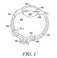
- FIG. 1presents a top cross-section of a human eye.
- FIG. 2presents a cross-section through the human eye that includes the layers of the outer and inner anatomical retina, as indicated by the inset of FIG. 1 .
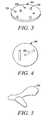
- FIG. 3illustrates one preferred shape of an implantable device.
- FIG. 4illustrates a first alternative shape of the implantable device of FIG. 3 .
- FIG. 5illustrates a second alternative shape of the implantable device of FIG. 3 .
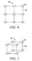
- FIG. 6is a two dimensional array of implantable devices.
- FIG. 7is a three dimensional array of implantable devices.
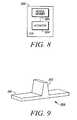
- FIG. 8is a schematic illustration of a mechanically activated object in accordance with one embodiment of the present invention.
- FIG. 9is a perspective view of a first exemplary device in accordance with the schema of FIG. 8 .
- FIG. 10is a top-cross section of an eye illustrating post-implantation placement of the device of FIG. 9 .
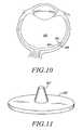
- FIG. 11is a perspective view of an alternative embodiment of the first exemplary device of FIG. 9 .
- FIG. 12is a perspective view of a second exemplary device in accordance with the schema of FIG. 8 .
- FIG. 13is a cross-section along line 12 - 12 ′ of FIG. 12 and further illustrating operation of the second device.
- FIG. 14is a cross-section of a third exemplary device in accordance with the schema of FIG. 8 .
- FIG. 15is a schematic illustration of a mechanically activated object in accordance with another embodiment of the present invention.
- FIG. 16is a top cross-section of an eye illustrating a class of exemplary devices in accordance with the schema of FIG. 15 .
- retinal diseasescause vision loss by partial to complete destruction of the vascular layers of the eye that include the choroid and choriocapillaris, both of which nourish the outer anatomical retina and a portion of the inner anatomical retina of the eye.
- a number of other retinal diseasescause vision loss due to partial to complete degeneration of one or both of the two anatomical retinal layers directly, due to inherent abnormalities of these layers.
- the components of the retinal layersinclude Bruch's membrane and retinal pigment epithelium which comprise the “outer anatomical retinal layer”, and the photoreceptor, outer nuclear, outer plexiform, inner nuclear, inner plexiform, amacrine cell, ganglion cell and nerve fiber layers which comprise the “inner anatomical retinal layer”, also known as the “neuroretina”.
- the outer portion of the neuroretinais comprised of the photoreceptor and bipolar cell layers and is also known as the “outer retina” which is to be distinguished from the “outer anatomical retinal layer” as defined above.
- Loss of function of the outer retinais commonly the result of dysfunction of the outer anatomical retinal layer that provides nourishment to the outer retina and/or to direct defects of the outer retina itself.
- the final common resultis dysfunction of the outer retina that contains the light sensing cells, the photoreceptors.
- Some of these “outer retina” diseasesinclude age-related macula degeneration, retinitis pigmentosa, choroidal disease, long-term retinal detachment, diabetic retinopathies, Stargardt's disease, choroideremia, Best's disease, and rupture of the choroid.
- the inner portion of the neuroretinahowever, often remains functionally and anatomically quite intact and may be activated by the appropriate stimuli.
- GFsgrowth factors
- NTGFsneurotrophic-type growth factors
- An irritant effectis also produced by the physical effect that includes a mechanical foreign-body effect, of an implant placed into or in contact with the retina.
- Such an irritant effectis akin to a mild damage effect on the retina which is known to upregulate the production of survival-type factors.
- an incision into the retinacalled a retinotomy
- certain survival-type factorsthat also temporarily slow down retina degeneration in a rat model of retinal degeneration (Peng et al., 1997).
- a non-electrical foreign body that is inert or almost inertis therefore capable of producing a chronic irritant effect that chronically upregulates endogenous survival factors in the retina and to produce a long-term slowdown or prevention of a retinal degenerative process.
- a system and methodare disclosed of placing a non-electrical physical and/or mechanical foreign body into or in contact with the retina to irritate and therefore chronically stimulate the upregulation of survival-type factors to slow down and/or prevent retinal degeneration.
- the subject matter of this applicationalso includes the devices used to produce the said chronic irritation of the retina.
- Such non-electrical chronic irritant devicestheoretically may have the ability to slow down the degeneration in other organ systems such as the central nervous system.
- the present inventiondiscloses both devices and novel methods to non-electrically irritate and/or stimulate the retina by physical and/or mechanical stimulation/irritation to improve large areas of retinal visual function and to protect the retina from degeneration.
- a subjectmay be a human being or a non-human animal, but is preferably a human.
- the individualhas suffered some type of retinal damage and/or degeneration that results in some degree of visual loss and/or has a condition that will result in retinal damage and/or degeneration.
- a healthy subjectdoes not have a condition that will result in retinal damage and/or degeneration and/or has not suffered retinal damage and/or degeneration.
- Improving visual functionrefers to improving a targeted function of the eye, selected by the artisan, and includes improving any to all of the following capabilities of the eye, retina and visual system: perception of brightness in the presence of light, perception of darkness in the absence of light, perceptions of contrast, color, shape, resolution, movement and visual field size.
- Primary visual degradationmeans loss of visual function due to malfunction of, damaged to, or degeneration of structures found in the eye.
- Secondary visual degradationmeans loss of visual function due to secondary damage, typically from lack of use of the vision-associated portions of the brain. Improving visual function means to improve the visual function of primary visual degradation, secondary visual degradation or both.
- the eye(or eyeball) has the usual definition in the art. Eye includes all interior and exterior surfaces, components, contents and cavities of the eye. The eye does not include the eyelid.
- the retina of the eyecan be divided into sectors as is commonly accepted in the art. Such sectors are described by the use of the terms temporal, nasal, superior, inferior, by clock hour designation, and by the number of degrees away from the macula.
- the temporal sector of the retinais the retina temporal to a perpendicular plane cutting through retina from the 12 o'clock to the 6 o'clock positions and through the macula.
- the superior sectoris the retina superior to a perpendicular plane cutting through the 9 o'clock to 3 o'clock positions and through the macula.
- the superior-temporal sectoris the intersection of these two sectors, a pie-shaped area delineated from the 9 o'clock position of the peripheral retina to the macula and then clockwise to the 12 o'clock position. More specific locations of the retina can be designated by degrees away from the macula and clock hour location: for example, 20 degrees away from the macula at the 3 o'clock (nasal) position. The number of degrees away from the macula is in visual axes degrees. These axes all intersect through the lens of the eye.
- the visual field sectorscorrespond oppositely to the retinal sectors as is commonly understood in the art.
- the superior-temporal sector of the retinacorresponds to the inferior-nasal portion of the visual field.
- device or other landmarkincludes all surrounding parts, but not the object, device or landmark, i.e., the object, device or landmark, together with the peripheral portion, constitutes the whole.
- Lightrefers not only to the electromagnetic spectrum that humans can readily perceive visually (approximately 400 nm to 750 nm), but also includes ultraviolet light ( ⁇ 400 nm in wavelength) as well as infrared light (>750 nm in wavelength).
- the inventioncan be used to improve visual function in subjects in which the retina is damaged by disease, degeneration, condition, or trauma and/or to slow down or stop the progression of damage by disease, degeneration, condition or trauma.
- diseases, conditions, degeneration or traumathat are particularly amenable to this treatment include age-related macula degeneration, retinitis pigmentosa, Leber's congenital amaurosis, Stargardt's disease, Best's disease, diabetic retinopathy, long-term retinal detachment, and choroidal damage.
- FIG. 1illustrates a section through the eyeball.
- the neuroretina 150comprises multiple layers of cells and structures (see FIG. 2 ).
- the photoreceptor components of the retinaare situated within the neuroretina which covers the internal posterior cavity of the eye, terminating anteriorly at the ora serrata 167 .
- the ciliary body 168 and the iris 162are covered by extensions of the retina, lacking photoreceptor components.
- the outermost layers of the eyeconsist of the sclera 164 and cornea 158 .
- the sclerais pierced by the emerging optic nerve 166 .
- the lens 160 and vitreous cavity 154are also indicated.
- the macula 169 of the retinais typically a 3 mm by 5 mm oval region, at the center of which is the fovea 170 .
- the layers of the eye at the posterior pole from inside to outsideare shown in FIG. 2 : internal limiting membrane 40 , nerve fiber layer 42 , ganglion and amacrine cell layer 44 , inner plexiform 46 , inner nuclear/bipolar cell layer 48 , outer plexiform 50 , outer nuclear layer 52 , and photoreceptor layer 54 , all of which constitute the anatomical inner retinal layer, also known as the neuroretina 56 .
- the retinal pigment epithelium 58 , and Bruch's membrane 60constitute the outer retinal layer 62 .
- the choriocapillaris 64 , and choroid 66comprise the choroidal vasculature 68 .
- the outer coat of the eyeis the sclera 70 .
- Light 156enters the retina as shown. As known in the art, a subretinal space is defined as the potential space existing between the outer anatomical retinal layer and the neuroretina.
- Any object that can provide a chronic or prolonged physical stimulation or irritation to the eyecan be used as a source of physical stimulation.
- These devicesmay include, but are not limited to, electrically inert objects, mechanically or electrically activated objects, and chemical or biological agents.
- the physical stimulationmay be provided by any object that can remain in physical contact with and/or irritate cells, such as retinal cells of an eye, for an extended period of time.
- the extended period of timemay be years, such as would be the case with a device that would be implanted in the eye and persist indefinitely in the eye unless it was purposefully extracted.
- the extended period of timemay be a limited time, for example one year, after which the implanted device or agent would biodegrade or otherwise be absorbed.
- the source of physical stimulationis at least one device or object that is electrically inactive such that it is neither photoactive, a source of electrical stimulation, nor in electrical communication with a source of electrical stimulation.
- the devicemay be constructed from silicon, metal, plastic, ceramic, glass, wood, sand or any of a number of materials.
- an object of any shape or depthmay be used. These shapes may include, but not be limited to, to geometric shapes, such as straight lines, circles, squares, rectangles, and triangles as well as three-dimensional shapes, such as balls, cubes, cylinders, or cones.
- the devicemay be a disk-shaped object 174 with or without fenestrations 176 , as shown in FIG. 3 .
- the object 174may be constructed to include various shape protrusions 178 .
- the object 180 shown in FIG. 4illustrates a spherical shape. Again, fenestrations 182 may be incorporated in the object to allow nutrients to pass through. Irregularly-shaped objects 184 , such as illustrated in FIG. 5 , may be also be used.
- the devicesmay be of various different dimensions, one preferred size range is greater than approximately 1 micron and less than approximately 20 mm in linear dimensions, and more preferably greater than approximately 0.5 mm and less than approximately 5 mm in linear dimensions.
- Substrates for such objectsinclude, without limitation, bio-absorbable polymers, silicon, plastics and other metals, and biomaterials. These devices can be implanted in any of the regions of an eye as discussed below. Many materials, shapes, sizes and devices may be used as long as they interact with cells in the eye to physically stimulate these cells. Also, in yet other embodiments, one or more electrically inert devices may be implanted in the eye in combination with one or more devices intended to supply electrical stimulation to the eye.
- the devicemay be an interconnected array of implantable elements.
- FIG. 6shows a two dimensional array 190 of implantable objects 186 interconnected by a flexible biocompatible mesh 188 .
- Each of the objects 186may be of the same or different shape and maintains its physical connection with one or more of the other objects while in the eye via the mesh 188 .
- the arraymay be a three dimensional array 192 of implantable objects 186 interconnected by a flexible mesh 188 .
- Other means to provide physical stimulationincludes implanting devices that deliver an irritant.
- an irritantFor example, oils, detergents, bile salts, etc. may be applied in small quantities that are yet sufficient to physically stimulate the cells.
- the irritantis packaged, such as in a capsule, so that the irritant is slowly released over time, and so that the “packaging” is ultimately absorbed by the body.
- biodegradable substancesinclude biodegradable polymers. Biodegradable polymers decompose when placed inside an organism and thus eliminate the need to remove the implant after the bioactive agent has been released, since the polymer will gradually break down and may be metabolized or excreted from the body.
- the decomposition of a biodegradable polymercan be observed as a decline in the molecular weight of the polymer over time.
- Polymer molecular weightscan be determined by a variety of methods including size exclusion chromatography (SEC), and are generally expressed as weight averages or number averages.
- SECsize exclusion chromatography
- a polymeris biodegradable if, when in phosphate buffered saline (PBS) of pH 7.4 and a temperature of 37° C., its weight-average molecular weight is reduced by at least 25% over a period of 6 months as measured by SEC.
- PBSphosphate buffered saline
- Polymers which could be useful as “packaging” capsulesinclude, but are not limited to, polyesters, such as poly(caprolactone), poly(glycolic acid), poly(lactic acid), poly(hydroxybutryate); copolymers of caprolactone, glycolic acid, lactic acid, and hydroxybutryate; polyanhydrides, such as poly(adipic anhydride); poly(para-dioxanone); poly(malic acid); polyamines; polyurethanes; polyesteramides; polyorthoesters; polyacetals; polyketals; polycarbonates; polyorthocarbonates; polyphosphazenes; poly(amino acids); chitin; chitosan; and copolymers and mixtures thereof.
- polyesterssuch as poly(caprolactone), poly(glycolic acid), poly(lactic acid), poly(hydroxybutryate); copolymers of caprolactone, glycolic acid, lactic acid, and hydroxybutryate
- polyanhydridessuch as poly
- Chemical or biological agentscan also be introduced into the eye to provide a prolonged stimulation to enhance rescue and retina functional improvement. This additional step is attractive because some factors, especially neurotrophic-type growth factors, may improve retinal function and provide limited neuronal rescue in eyes with retinal degeneration and dysfunction.
- growth factorsinclude, but are not limited to, glial cell line-derived neurotrophic factor (GDNF), nerve growth factor (NGF), brain derived neurotrophic growth factor (BDNGF), neurotropin-3 (NT-3), neurotropin-4 (NT-4), neurotropin-5 (NT-5), ciliary neurotropic factor (CNTF) and fibroblastic growth factor (FGF).
- growth factorscan be delivered to the eye by coating the device with growth factor(s) before implantation, by injection of the growth factor(s) into the locations of the subretinal space, vitreous cavity, subconjunctival space, subscleral space, and/or the anterior chamber either singly or in combination with each other, as a single dose or as multiple repeat doses before, during and/or after implantation of the device(s).
- the chronic physical stimulation provided by at least one devicemay be provided subretinally, epiretinally, subsclerally (between the sclera and choroid; also referred to as suprachoroidally), subchoroidally (between the choroid and Bruch's membrane), on the scleral surface, on or under the conjuctival surface and/or from or within any structure of the eye.
- Other means of providing physical simulation to the retina and eyemay include devices that deliver chronic stimulation from the underside of the eyelid(s).
- physical stimulationis from the subretinal space which is an area that is in close proximity to the damaged retinal cells.
- the chronically irritating/stimulating agentcan be inserted in a way that it is placed in direct contact with the damaged retinal cells.
- the chronically irritating/stimulating agentcan be placed adjacent to, but not in direct contact with, the damaged retinal cells.
- healthy retinal cellsmay be chronically stimulated to produce and release growth factors, such as neurotrophic growth factors, to help enhance retinal cell function.
- the physical stimulationis preferably in the subretinal space in the periphery and/or mid-periphery of the eye, outside of the macula.
- more than one devicemay be implanted, if needed, in an eye to stimulate a larger area of the retina, and multiple devices can be implanted in paracentral locations such as one in each of the four paracentral quadrants, approximately, but not limited to, 5 to 80 degrees peripheral to the macula.
- one or more devicesmay be implanted in the macular region of the eye.
- the implantsmay be placed in the subretinal space in the mid-periphery approximately 20 degrees away from the macula, using one device or up to approximately four devices evenly spaced on a perimeter in the midperiphery.
- Cells to stimulateinclude the remaining cells of the inner retina.
- an implantable deviceis designed to be implanted onto the epiretinal surface (i.e. on the nerve fiber layer side) of the retina. It is retained in position by retinal tacks, biocompatible glues, or other means.
- subconjunctival/scleral placement of the deviceresults in less efficient electrical stimulation of the retina compared to a subretinally or epiretinally placed device, but the extraocular location of the device decreases the surgical risk to a patient since intraocular surgery would not be required for its implantation.
- the subconjunctival/scleral placement of a devicealso allows a stable device position to be achieved without fixating devices or glues (i.e., the device is held in place between the conjunctiva and sclera).
- electrically inert objects, chemical, and/or biological agentscan be inserted into an eye in several ways.
- Chemical and biological agents, such as growth factorscan be delivered to the eye by coating a substrate with these factor(s) before implantation and/or by injecting these factor(s) into the locations of the subretinal space, vitreous cavity, subconjunctival space, subscleral/suprachoroidal space, subchoroidal space and/or the anterior chamber either singly or in combination with each other, as a single dose or as multiple repeat doses independent of, before, during and/or after implantation of the coated substrate or other electrical stimulating device.
- Electrically inert object(s)can be delivered to the eye by placing it directly into the subretinal space, vitreous cavity, subconjunctival space, subscleral space, and/or the anterior chamber through implantation or injection performed as previously described for the retinal implantable devices.
- FIGS. 8-16Further embodiments in accordance with the present invention, particularly mechanically activated embodiments, are further illustrated in FIGS. 8-16 .
- mechanically activated embodimentsare characterized by the use of mechanical action or forces to stimulate or irritate cells of the eye, as opposed to physical embodiments which, more generally, refer to the material presence of an object or device to effectuate stimulation/irritation and, hence, treatment of the eye.
- each of the devices described beloware dimensioned to fit on or within the eye, typically on the order of a few millimeters in length, although sub-millimeter devices or devices greater than around 10 millimeters may be possible.
- the thicknesses of such devicesare substantially smaller than the lengths, typically on the order of tens or hundreds of microns although, once again, larger or smaller thicknesses may be possible as a matter of design.
- FIG. 8A first schema of mechanically activated embodiments is illustrated in FIG. 8 wherein at least one moving member 202 is acted upon by an actuator 204 , both of which are implanted on or within an eye 200 .
- the moving member 202is configured to contact at least a portion of the eye, including any of the various structures of the eye, preferably a retina of the eye.
- the moving member 202may be equally configured for implantation in virtually any location of the eye, e.g., epiretinally, subchoroidally, subsclerally/suprachoroidally, sclerally, on the conjunctiva, etc.
- an elementis configured for a particular application, in part, through the choice of dimensions, materials and/or shape suitable for the particular application. Regardless of its location when implanted, the moving member 202 , when acted upon by the actuator 204 , imparts displaces the tissues of the eye with which it is in contact thereby stimulating the eye. As noted above, experimental studies suggest that such stimulation or irritation may induce a beneficial upregulation of endogenous survival-type factors.
- FIG. 9A first exemplary device 208 in accordance with the schema of FIG. 8 is illustrated in FIG. 9 .
- the device 208comprises a moving member 210 that is generally planar and fabricated from biocompatible, biodurable materials such as glass, polyimide, PDMA, parylene C, silicone, silicon, silicon dioxide, diamond-like materials, metals including titanium, iridium, stainless steel, gold, aluminum, various oxides thereof, etc.
- biocompatible, biodurable materialssuch as glass, polyimide, PDMA, parylene C, silicone, silicon, silicon dioxide, diamond-like materials, metals including titanium, iridium, stainless steel, gold, aluminum, various oxides thereof, etc.
- a combination of materialsmay be used to meet different design criteria, e.g., a first material to provide structural strength coated with one or more additional materials to provide biocompatibility and/or biodurability.
- the moving member 210may be curved or comprise multiple conjoined non-coplanar elements, preferably to generally match the curvature of the location of the eye where it will be implanted.
- the moving member 210may also be fabricated to include various structures or protuberances on any of its surfaces designed to maximize and/or localize mechanical stimulation/irritation.
- an actuator 212comprises at least one projecting arm coupled to (e.g., integrally formed with) the moving member 210 .
- the actuator 212may be fabricated from the same or different materials as the moving member 210 , with the additional design constraint that the actuator 212 is intended to directly contact the fluid material in the vitreous cavity.
- a single actuator 212is illustrated in FIG. 9 , more than one such actuator could be employed, and the actuator(s) can be positioned differently relative to the moving member 210 (e.g., at the ends rather than at or near the middle).
- the actuator(s)need not project perpendicularly from the moving member 210 , as shown, but may project at any convenient angle.
- the actuator(s)need not be formed as substantially planar structures, as shown, but may incorporate various divergent, convergent and/or curving surfaces or vanes as a matter of design choice. All edges of the device can be rounded or otherwise smoothed out to minimize the likelihood of catching and tearing of delicate ocular tissues.
- the actuator 212is intended to contact the fluid material (e.g., comprising the vitreous or a replacement material) within the vitreous cavity directly.
- the vitreouscomprises a clear, gel-like, relatively viscous material and, as a result, presents an inertial differential at the surface of the retina.
- a replacement material within the vitreous cavitysuch as saline or aqueous, although less viscous, would still impart an inertial differential at the retinal surface. That is, as the eye moves by rotating within the orbit, differences in movement of the fluid material within the vitreous cavity relative to the surface of the retina are induced. As illustrated in FIG.
- the actuator 212exploits these differences by extending through the retina 214 into the fluid material within the vitreous cavity 215 . As the eye moves, movement of the fluid material induces movement in the actuator 212 and, consequently, the moving member 210 . Through selection of appropriate dimensions of the actuator 212 and moving member 210 , and/or the rigidity of the connection between the actuator and the moving member 210 , a controlled amount of movement may be induced in the moving member 210 to achieve a therapeutically-effective level of stimulation/irritation. As illustrated, the actuator 212 will be more susceptible to forces applied parallel to the longitudinal axis of the device, as opposed to at an angle relative to the longitudinal axis. An alternative embodiment is illustrated in FIG.
- the moving member 210 ′is circular to provide maximum stimulation to surrounding tissues regardless of the direction of the forces present at the actuator 212 ′. Note that, although a single device is shown in FIG. 10 , it is understood that multiple such devices could be implanted within an eye.
- the device 220 of FIGS. 12 and 13is representative of a family of devices in which a body member is provided to support the moving member.
- the body member 221comprises a relatively low-profile base supporting the moving member 222 through integrally-formed supports 224 .
- the moving member 222 and supports 224form a torsional resonator-like structure sometimes found in the art of micro-electromechanical systems (MEMS).
- MEMSmicro-electromechanical systems
- such a devicecan be fabricated from silicon using well-known processing techniques, although other materials may be equally employed. Silicon construction is particularly advantageous because it provides to the opportunity to incorporate electrical elements.
- the moving member 222is positioned over a cavity 226 formed within the body member 221 .
- one or more electrodes 230are formed.
- corresponding electrodesare deposited on or integrally formed with the moving member 222 substantially in alignment with the electrode(s) 230 residing within the cavity 226 .
- application of a voltage 234 across the cavity electrodes 230 and the moving member 222 electrodeswill give rise to electrostatic attractive and/or repulsive forces. For example, in FIG.
- the voltage source 234could take any of a number of forms.
- photovoltaic elementssuch as photodiodes can be incorporated into the device 220 (particularly where the body member 221 is fabricated from silicon) and electrically coupled to the electrodes using well known techniques. Entire arrays of moving members could be created along side corresponding photovoltaic elements that supply the necessary electrical charges to one or more neighboring devices.
- more than one device 220could be powered by a larger, shared photovoltaic device or devices. Regardless, in this manner, ambient (or artificially provided) light can be used to derive the electrical charges used to induce movement in the device(s).
- one or more extraocular electrical sourcescould be employed, although such an approach is less preferred given the likely need for implanted wires or less efficient wireless power transmission.
- a cavity 244is formed in a body member 242 , preferably but not necessarily formed of silicon, and sealed off with a deflectable, biocompatible/biodurable membrane 250 .
- the membrane 250serves as the moving member.
- the membrane 250which may hermetically seal the cavity 244 and may be fabricated from silicone, PMMA, parylene, latex, diamond-like carbon or other materials offering good biocompatibility and flexibility. Note that, although a single cavity and membrane are illustrated in FIG. 14 , multiple cavities and/or multiple membranes may be equally employed.
- An actuator 248provided within the cavity 244 , is schematically illustrated in FIG. 14 .
- the actuator 248operates to impart a force (illustrated by the dashed arrow) on the membrane 250 such that the membrane is displaced, thereby coming into contact with, and likewise displacing, adjacent ocular tissues.
- the actuator 248is coupled to a voltage source 252 that provides power such that the actuator can impart force on the membrane 250 .
- the voltage source 252preferably comprises one or more photovoltaic devices, preferably integrally formed in the body member 242 , although other voltage sources may be equally employed. Additionally, an array of such membrane-based devices could be formed within the body member 242 . Regardless, various devices or combination of devices can be employed to implement the actuator 248 , several of which are discussed below.
- a fluidpreferably having a relatively low boiling point and exhibiting good biocompatibility
- a heating elementis also placed within the cavity while retaining a hermetic seal around the cavity.
- the heating elementis further coupled to the voltage source 252 .
- the voltage source 252 , heating element, cavity 244 and fluidfunction as the actuator.
- the resulting heatcauses the fluid to expand, leading to a pressure increase within the cavity 244 .
- the increase in pressurecauses the membrane 250 to deflect (illustrated in dashed lines) and thereby impinge upon adjacent ocular tissues.
- the fluidcools and condenses, pressure decreases within the cavity, and the membrane returns to its relaxed state.
- the cavity 244is provided with one or more bleed or flow orifices (for example, formed in the floor of the cavity 244 ) such that, after implantation of the device 240 , tissue fluids slowly ingress into the cavity 244 .
- At least two electrodesare fabricated into the cavity floor and connected to the voltage source 252 .
- the voltage source 252 , electrodes, cavity 244 and tissue fluidscollectively function as the actuator.
- electrolysiscreates gas bubbles at the electrodes.
- the size of the gas bubblesis proportional to the applied power.
- the increased volume of the gas bubbles within the cavity 244causes the membrane 250 to deflect. Thereafter, at the end of each stimulation cycle, the cavity is allowed to slowly equilibrate, via the flow orifices, with the tissue fluids and membrane 250 returns to its original position.
- the actuator 248may comprise a fulcrum and lever arrangement, disposed within the cavity 244 , in which one end of the lever is coupled to a shape-altering material.
- a shape-altering materialfor example, so-called electro-active polymers (EAPs) or “artificial muscles” which alter their shape in response to an applied voltage may be employed for this purpose.
- EAPselectro-active polymers
- U.S. Pat. No. 6,511,508 and U.S. Patent Application No. 20030139808describe the use of a variety of EAP as well as other artificial muscle materials that may be used in conjunction with the present invention, the teachings of which are incorporated herein by this reference.
- one end of a length of EAPis affixed within the cavity 244 while the other end of the length of EAP is coupled to one end of the lever. Additionally, the EAP is coupled to the voltage source 252 .
- the fulcrum, lever, EAP and voltage source 252function as the actuator in this instance.
- movementcan be induced in the EAP.
- movement by the EAPcauses the lever to rotate about the fulcrum.
- the rotation of the levercauses the membrane 250 to deflect, thereby displacing adjacent ocular tissues.
- the lever and membrane 250return to their original positions.
- piezoelectric materialsi.e., materials that alter their shape in response to an applied voltage
- a moving membercan be fashioned directly out of a piezoelectric material such that the voltage source functions as the actuator, or a non-piezoelectric material could be used to fashion a moving member that in turn is mechanically coupled to a piezoelectric actuator.
- the EAPs described aboverather than being used to induce movement in another structural element, could be directly fashioned into a moving member such that motion induced in the EAP is directly transferred to, for example, a deflectable membrane without the aid of an intervening device. Regardless, biocompatible materials are preferred.
- FIG. 15A second schema of mechanically activated embodiments is illustrated in FIG. 15 wherein at least one moving member 302 , implanted on or within the eye, is acted upon by an extraocular actuator 304 .
- the moving member 302is configured to contact at least a portion of the eye, including any of the various structures of the eye, preferably a retina of the eye.
- the moving member 302may be equally configured for implantation in virtually any location of the eye, e.g., epiretinally, subsclerally/suprachoroidally, sclerally, subchoroidally, on the conjunctiva, etc. Regardless of its location when implanted, the moving member, when acted upon by the actuator 304 , displaces the tissues of the eye with which it is in contact thereby stimulating the eye.
- the actuator 304is extraocular (which is not necessarily exclusive of being implanted within the body, e.g., intraorbitally) but nevertheless acts upon the moving member 302 .
- actuators suitable for this purposeinclude oscillators that induce mechanical waves in the ocular tissues and magnetic fields that penetrate the ocular tissues.
- Further examplesinclude actuators that are mechanically and/or electrically coupled through an appropriate linkage to the moving member, which linkage penetrates the intervening ocular tissues.
- FIG. 16illustrates a system in accordance with the schema of FIG. 15 in which an implanted moving member 312 is acted upon by an extraocular actuator 314 .
- the moving member 312comprises an object or device having a natural vibration frequency.
- the objectWhen provided with an appropriate vibratory stimulus, the object will likewise vibrate at its natural vibration frequency.
- a vibratory stimulus that is most closely tuned to a natural frequency of an objectwill induce the greatest magnitude vibrations in the object.
- the nature of the vibratory stimuluscan be controlled to likewise control the magnitude of the induced vibrations.
- the particular resonant frequencies of a given object(not accounting for environmental or other damping effects) will depend on the physical characteristics of the object, e.g., its mass, shape, dimensions, etc.
- the moving member 312can be designed to have a specific natural frequency. Being implanted, the moving member 312 is preferably fabricated from and/or coated with suitably biocompatible/biodurable materials.
- the actuator 314in this case a mechanical oscillator, generates mechanical waves 316 (substantially at the natural frequency of the moving member, optimally) that propagate through the ocular media and impinge upon the moving member 312 .
- vibrations of controlled (but variable) magnitudesare imparted by the moving member 312 upon the surrounding ocular tissues (e.g., the retina) thereby stimulating/irritating the tissues.
- Techniques for generating mechanical waves, and hence for implementing an actuator 314 capable of generating such mechanical wavesare well known in the art and need not be described in further detail here.
- such an oscillatorcan be mechanically coupled directly to a surface of the eyeball through an appropriate (e.g., fluid) interface, or indirectly through tissues or structures adjacent the eyeball (e.g., through the eyelids or bones of the orbit).
- an external actuator 314is depicted in FIG. 16 , it is understood that the actuator 314 could be implanted within the body and yet remain extraocular. For example, through the use of appropriate electrical connections, such an actuator could be implanted within the orbit of an eye.
- the moving member 312comprises a magnet. Movement of a magnet may be induced by changes (relative to the magnet) in a magnetic field in which the magnet resides. Thus, movement of the magnet itself through a static magnetic field will induce further movement of the magnet and/or the magnetic field itself can be varied.
- the moving member 312may comprise a suitably-dimensioned magnet that is either fashioned from biocompatible/biodurable materials or that is rendered biocompatible/biodurable through suitable coatings such as, but limited to, parylene.
- the actuator 314may comprise a source of a time-varying magnetic field 316 , such as an electromagnet.
- the time-varying magnetic field 316When the time-varying magnetic field 316 impinges upon the magnet, it induces movement in the magnet 312 commensurate with the rate of variance of the magnetic field. By adjusting the strength and rate of variance of the magnetic field, the movement of the magnet 312 may likewise be controlled.
- a static, time-invariant magnetic fieldmay be employed such that movement of the magnet through the static magnetic field induces vibrations in the dipole.
- a sufficiently powerful magnetic fieldcould be established extraocularly (e.g., through extraocular implantation of permanent magnets or placement of sufficiently powerful magnets outside the head). Given the natural movement of the eye, the implanted magnet 312 will move through the static magnetic field, thereby inducing further movement of the magnet.
- the present inventionprovides mechanically activated objects or devices for use in treating degenerative retinal diseases.
- the present inventionteaches various mechanically activated approaches for eliciting such stimulus. In this manner, it may be possible to treat degenerative retinal diseases for which there were no previous treatments or cure.
Landscapes
- Health & Medical Sciences (AREA)
- Life Sciences & Earth Sciences (AREA)
- Veterinary Medicine (AREA)
- Public Health (AREA)
- General Health & Medical Sciences (AREA)
- Animal Behavior & Ethology (AREA)
- Biomedical Technology (AREA)
- Engineering & Computer Science (AREA)
- Ophthalmology & Optometry (AREA)
- Nuclear Medicine, Radiotherapy & Molecular Imaging (AREA)
- Radiology & Medical Imaging (AREA)
- Rehabilitation Therapy (AREA)
- Physical Education & Sports Medicine (AREA)
- Pain & Pain Management (AREA)
- Epidemiology (AREA)
- Prostheses (AREA)
- Materials For Medical Uses (AREA)
- Medicinal Preparation (AREA)
Abstract
Description
Claims (17)
Priority Applications (1)
| Application Number | Priority Date | Filing Date | Title |
|---|---|---|---|
| US12/576,891US7981062B2 (en) | 2001-06-29 | 2009-10-09 | Mechanically activated objects for treatment of degenerative retinal disease |
Applications Claiming Priority (5)
| Application Number | Priority Date | Filing Date | Title |
|---|---|---|---|
| US30187701P | 2001-06-29 | 2001-06-29 | |
| US10/056,793US7031776B2 (en) | 2001-06-29 | 2002-01-23 | Methods for improving damaged retinal cell function |
| US10/186,295US20030028225A1 (en) | 2001-06-29 | 2002-06-28 | Methods for improving damaged retinal cell function using physical and/or mechanical stimulation |
| US10/822,437US20050033202A1 (en) | 2001-06-29 | 2004-04-12 | Mechanically activated objects for treatment of degenerative retinal disease |
| US12/576,891US7981062B2 (en) | 2001-06-29 | 2009-10-09 | Mechanically activated objects for treatment of degenerative retinal disease |
Related Parent Applications (1)
| Application Number | Title | Priority Date | Filing Date |
|---|---|---|---|
| US10/822,437ContinuationUS20050033202A1 (en) | 2001-06-29 | 2004-04-12 | Mechanically activated objects for treatment of degenerative retinal disease |
Publications (2)
| Publication Number | Publication Date |
|---|---|
| US20100121231A1 US20100121231A1 (en) | 2010-05-13 |
| US7981062B2true US7981062B2 (en) | 2011-07-19 |
Family
ID=35394646
Family Applications (2)
| Application Number | Title | Priority Date | Filing Date |
|---|---|---|---|
| US10/822,437AbandonedUS20050033202A1 (en) | 2001-06-29 | 2004-04-12 | Mechanically activated objects for treatment of degenerative retinal disease |
| US12/576,891Expired - Fee RelatedUS7981062B2 (en) | 2001-06-29 | 2009-10-09 | Mechanically activated objects for treatment of degenerative retinal disease |
Family Applications Before (1)
| Application Number | Title | Priority Date | Filing Date |
|---|---|---|---|
| US10/822,437AbandonedUS20050033202A1 (en) | 2001-06-29 | 2004-04-12 | Mechanically activated objects for treatment of degenerative retinal disease |
Country Status (2)
| Country | Link |
|---|---|
| US (2) | US20050033202A1 (en) |
| WO (1) | WO2005110326A2 (en) |
Cited By (7)
| Publication number | Priority date | Publication date | Assignee | Title |
|---|---|---|---|---|
| US20130131797A1 (en)* | 2010-04-01 | 2013-05-23 | Imi Intelligent Medical Implants Ag | Retinal implant and visual prosthesis incorporating such an implant |
| US11305118B2 (en) | 2018-11-30 | 2022-04-19 | Biovisics Medical, Inc. | Head worn apparatuses for vision therapy |
| US11338139B2 (en) | 2018-10-01 | 2022-05-24 | Biovisics Medical, Inc. | System and methods for controlled electrical modulation for vision therapy |
| US11471680B2 (en) | 2019-04-10 | 2022-10-18 | Biovisics, Inc. | Systems and interfaces for ocular therapy |
| US11511112B2 (en) | 2019-06-14 | 2022-11-29 | Biovisics Medical, Inc. | Wearable medical device |
| US11738195B2 (en) | 2018-11-20 | 2023-08-29 | Nuenerchi, Inc. | Electrical stimulation device for applying frequency and peak voltage having inverse relationship |
| US12023498B2 (en) | 2019-07-12 | 2024-07-02 | Biovisics Medical, Inc. | Ocular therapy modes and systems |
Families Citing this family (27)
| Publication number | Priority date | Publication date | Assignee | Title |
|---|---|---|---|---|
| US7031776B2 (en)* | 2001-06-29 | 2006-04-18 | Optobionics | Methods for improving damaged retinal cell function |
| US20050033202A1 (en)* | 2001-06-29 | 2005-02-10 | Chow Alan Y. | Mechanically activated objects for treatment of degenerative retinal disease |
| WO2006002070A2 (en) | 2004-06-15 | 2006-01-05 | Novavision, Inc. | Method and device for guiding a user's head during vision training |
| US8021384B2 (en)* | 2005-07-26 | 2011-09-20 | Ram Weiss | Extending intrabody capsule |
| US20070093877A1 (en)* | 2005-10-26 | 2007-04-26 | Beecham Michael C | System for maintaining normal health of retinal cells and promoting regeneration of retinal cells |
| EP1968427A2 (en) | 2005-12-16 | 2008-09-17 | Novavision, Inc. | Adjustable device for vision testing and therapy |
| JP2009533157A (en) | 2006-04-12 | 2009-09-17 | プロテウス バイオメディカル インコーポレイテッド | Embedded sealed structure without voids |
| US8202272B2 (en) | 2007-07-19 | 2012-06-19 | Avedro, Inc. | Eye therapy system |
| US8992516B2 (en)* | 2007-07-19 | 2015-03-31 | Avedro, Inc. | Eye therapy system |
| US8469952B2 (en)* | 2008-01-23 | 2013-06-25 | Avedro, Inc. | System and method for positioning an eye therapy device |
| US8348935B2 (en) | 2008-01-23 | 2013-01-08 | Avedro, Inc. | System and method for reshaping an eye feature |
| US20090187173A1 (en)* | 2008-01-23 | 2009-07-23 | David Muller | System and method for reshaping an eye feature |
| US8409189B2 (en)* | 2008-01-23 | 2013-04-02 | Avedro, Inc. | System and method for reshaping an eye feature |
| TWI351271B (en)* | 2008-03-31 | 2011-11-01 | Univ Nat Taiwan | Artificial sphincter system |
| EP2291156A4 (en)* | 2008-05-30 | 2014-02-12 | Univ Colorado Regents | NON-INVASIVE DEVICE FOR LOWERING INTRAOCULAR PRESSURE |
| EP2346457A4 (en)* | 2008-09-19 | 2012-03-07 | Avedro Inc | Eye therapy system |
| US8460278B2 (en)* | 2008-10-01 | 2013-06-11 | Avedro, Inc. | Eye therapy system |
| JP2012508087A (en)* | 2008-11-11 | 2012-04-05 | アヴェドロ・インコーポレーテッド | Eye treatment system |
| US20100241060A1 (en)* | 2009-03-18 | 2010-09-23 | Roizman Keith | Surgical devices and methods |
| US20100280509A1 (en)* | 2009-04-02 | 2010-11-04 | Avedro, Inc. | Eye Therapy System |
| WO2010115121A1 (en)* | 2009-04-02 | 2010-10-07 | Avedro, Inc. | Eye therapy system |
| EP2413832A1 (en)* | 2009-04-02 | 2012-02-08 | Avedro, INC. | Eye therapy system |
| US8177778B2 (en)* | 2009-10-30 | 2012-05-15 | Avedro, Inc. | System and method for stabilizing corneal tissue after treatment |
| US9308126B2 (en) | 2010-11-29 | 2016-04-12 | The Regents Of The University Of Colorado, A Body Corporate | Non-invasive devices and methods for lowering intra-ocular pressure |
| BR122014004140B8 (en) | 2011-08-22 | 2023-03-28 | Bayer Cropscience Ag | RECOMBINANT VECTOR OR RECOMBINANT CONSTRUCTION, AS WELL AS METHODS FOR OBTAINING AND PRODUCING A COTTON PLANT OR PLANT CELL TOLERANT TO AN HPPD INHIBITOR, AND FOR CULTIVATING A FIELD OF COTTON PLANTS |
| US10058505B2 (en)* | 2015-03-22 | 2018-08-28 | Zeynab Mousavikhamene | Transscleral drug delivery |
| KR101716776B1 (en)* | 2015-05-21 | 2017-03-15 | 서울대학교산학협력단 | Non-Invasive Retinal Stimulator Using Time-Varying Magnetic Field |
Citations (154)
| Publication number | Priority date | Publication date | Assignee | Title |
|---|---|---|---|---|
| US793004A (en) | 1904-07-23 | 1905-06-20 | Frank Howard May | Eye-massage machine. |
| US1684860A (en) | 1927-03-12 | 1928-09-18 | De Forest B Catlin | Eye-treating apparatus |
| US2525381A (en) | 1947-09-25 | 1950-10-10 | Tower Paul | Contact-type electrode holder |
| US2721316A (en) | 1953-06-09 | 1955-10-18 | Joseph D Shaw | Method and means for aiding the blind |
| US2760483A (en) | 1953-10-29 | 1956-08-28 | Tassicker Graham Edward | Retinal stimulator |
| US3320947A (en) | 1963-10-25 | 1967-05-23 | Knoll Max Hans | Device for the excitation of nerve networks |
| US3594823A (en) | 1969-02-11 | 1971-07-27 | Patent Management Inc | Visual substitution system with receptor scanning means |
| US3628193A (en) | 1969-02-19 | 1971-12-21 | Inst Of Medical Sciences The | Tactile image projection system |
| US3699970A (en) | 1969-06-26 | 1972-10-24 | Nat Res Dev | Striate cortex stimulator |
| US3766311A (en) | 1972-04-26 | 1973-10-16 | H Boll | Sensory substitution system |
| US3769961A (en) | 1972-07-20 | 1973-11-06 | I Fatt | Conjunctival device |
| US3848608A (en) | 1973-07-23 | 1974-11-19 | Gen Electric | Subject integument spatial stimulator |
| US3893444A (en) | 1972-07-20 | 1975-07-08 | Univ California | Non-invasively measuring arterial oxygen tension |
| US3914800A (en) | 1974-06-06 | 1975-10-28 | Inst Of Medical Sciences | Fluid mechanical tactile oscilloscope to augment the five senses |
| US3995659A (en) | 1974-06-28 | 1976-12-07 | Pres Block S.P.A. | Quick-coupling valved joint for pipes embodying valved male and female coupling elements |
| US3995635A (en) | 1971-09-09 | 1976-12-07 | Alza Corporation | Ocular insert |
| US3998659A (en) | 1974-01-28 | 1976-12-21 | Texas Instruments Incorporated | Solar cell with semiconductor particles and method of fabrication |
| US4001867A (en) | 1974-08-22 | 1977-01-04 | Dionics, Inc. | Semiconductive devices with integrated circuit switches |
| US4018218A (en) | 1975-03-12 | 1977-04-19 | Carlson James E | Method and apparatus for sleep induction |
| SU554863A1 (en) | 1975-08-07 | 1977-04-25 | Московский научно-исследовательский институт глазных болезней им.Гельмгольца | Device for irradiating the eye with ultrasonic vibrations |
| US4089329A (en) | 1976-03-18 | 1978-05-16 | University Of Utah Research Institute | Noninvasive, continuous intraocular pressure monitor |
| US4211474A (en) | 1977-01-31 | 1980-07-08 | Compagnie Generale D'electricite | Ultra-rapid electro-optical shutter |
| US4251887A (en) | 1979-04-02 | 1981-02-24 | Anis Aziz Y | Posterior chamber capsular lens implant and method for implantation of the lens |
| US4271841A (en) | 1980-01-31 | 1981-06-09 | Medtronic, Inc. | Electro-ocular stimulation system |
| US4272910A (en) | 1979-07-31 | 1981-06-16 | Danz W R | Ocular prosthetic or the like |
| SU839529A1 (en) | 1976-10-04 | 1981-06-23 | Kulyakin Mikhail | Method of treating dystrophy of eye retina,choroid and partial atrophy of optic nerves |
| US4326529A (en) | 1978-05-26 | 1982-04-27 | The United States Of America As Represented By The United States Department Of Energy | Corneal-shaping electrode |
| SU939020A1 (en) | 1980-07-07 | 1982-06-30 | Предприятие П/Я В-8117 | Device for treating by magnetic field |
| SU1044283A1 (en) | 1981-07-23 | 1983-09-30 | Научно-Исследовательский Институт Экспериментальной Медицины Амн Ссср | Method of restoring optic nerve conduction at damage |
| US4484922A (en) | 1981-06-25 | 1984-11-27 | Rosenwald Peter L | Occular device |
| SU1139446A1 (en) | 1982-09-24 | 1985-02-15 | Starostin Vladimir A | Applicator for eye magnetotherapy |
| US4525776A (en) | 1980-06-02 | 1985-06-25 | Bell Telephone Laboratories, Incorporated | Arithmetic logic unit arranged for manipulating bits |
| US4551149A (en) | 1982-02-16 | 1985-11-05 | Michael Sciarra | Prosthetic vision system |
| US4600004A (en) | 1982-09-08 | 1986-07-15 | Osvaldo Lopez | Intraocular lens holder and inserter |
| US4601545A (en) | 1984-05-16 | 1986-07-22 | Kern Seymour P | Variable power lens system |
| US4603697A (en) | 1985-01-07 | 1986-08-05 | William Kamerling | System for preventing or treating open angle glaucoma and presbyopia |
| US4614193A (en) | 1984-01-09 | 1986-09-30 | Pain Suppression Labs, Inc. | Electronic glaucoma treatment apparatus and methodology |
| US4628933A (en) | 1985-07-23 | 1986-12-16 | Michelson Robin P | Method and apparatus for visual prosthesis |
| US4664117A (en) | 1984-10-09 | 1987-05-12 | Beck Stephen C | Apparatus and method for generating phosphenes |
| US4667676A (en) | 1985-06-17 | 1987-05-26 | Audimax, Inc. | Method of evaluating the vestibular system |
| US4679572A (en) | 1986-03-11 | 1987-07-14 | Intermedics, Inc. | Low threshold cardiac pacing electrodes |
| EP0233789A2 (en) | 1986-02-21 | 1987-08-26 | THE COOPER COMPANIES, INC. (formerly called CooperVision, Inc.) | Tool for inserting an intraocular lens |
| SU1386208A1 (en) | 1986-07-14 | 1988-04-07 | В.А. Нуритдинов | Apparatus for electrophoresis in the eye tissue |
| SU1395316A2 (en) | 1984-07-25 | 1988-05-15 | 2-й Московский государственный медицинский институт им.Н.И.Пирогова | Apparatus for physiotherapy of the eye |
| SU1409264A1 (en) | 1986-07-18 | 1988-07-15 | Центральный институт усовершенствования врачей | Method of introducing medicinal substance in diseases of the eye posterior sector |
| EP0084621B1 (en) | 1982-01-22 | 1989-02-01 | International Business Machines Corporation | Semiconductor signal conversion device using photon coupling |
| US4810050A (en) | 1985-05-24 | 1989-03-07 | British Telecommunications Public Limited Company | Optical inverter and logic devices using same with buffer limited electrical interface |
| US4832202A (en) | 1986-05-22 | 1989-05-23 | General Foods Limited | Containers |
| US4873448A (en) | 1986-04-30 | 1989-10-10 | Omron Tateisi Electronics Co. | Input circuit having a photo-coupler with bi-directional indicator |
| US4874237A (en) | 1987-05-07 | 1989-10-17 | Lions Eye Inst. Of Western Australia | Electroretinogram apparatus |
| EP0325201A3 (en) | 1988-01-20 | 1990-01-31 | Etama Ag | Stimulating device to improve the sight of persons with a poor sight |
| US4955378A (en) | 1988-05-02 | 1990-09-11 | University Of South Florida | Apparatus and methods for performing electrofusion at specific anatomical sites |
| US4978842A (en) | 1989-04-21 | 1990-12-18 | At&T Bell Laboratories | Programmable optical logic device with complementary inputs |
| US4979508A (en) | 1984-10-09 | 1990-12-25 | Beck Stephen C | Apparatus for generating phosphenes |
| US4989605A (en) | 1989-03-31 | 1991-02-05 | Joel Rossen | Transcutaneous electrical nerve stimulation (TENS) device |
| US5016633A (en) | 1989-08-08 | 1991-05-21 | Chow Alan Y | Artificial retina device |
| US5024223A (en) | 1989-08-08 | 1991-06-18 | Chow Alan Y | Artificial retina device |
| US5025811A (en) | 1990-02-16 | 1991-06-25 | Dobrogowski Michael J | Method for focal destruction of eye tissue by electroablation |
| US5070860A (en)* | 1987-12-04 | 1991-12-10 | Grounauer Pierre Alain | Retractor device for human or animal tissue |
| US5099829A (en) | 1990-04-25 | 1992-03-31 | Wu An Chuan | Massage device good for eyes |
| US5109846A (en) | 1989-05-22 | 1992-05-05 | Physiodynamics, Inc. | Apparatus and method for electrotherapeutic treatment of structures associated with the eye |
| US5109844A (en) | 1990-10-11 | 1992-05-05 | Duke University | Retinal microstimulation |
| US5130528A (en) | 1991-03-01 | 1992-07-14 | International Business Machines Corporation | Opto-photo-electric switch |
| US5130776A (en) | 1989-03-16 | 1992-07-14 | Landis & Gyr Betriebs Ag | Ultraviolet-light photodiode |
| SU1757666A1 (en) | 1990-11-14 | 1992-08-30 | Одесский Медицинский Институт Им.Н.И.Пирогова | Method for modeling the central dystrophy of the retina |
| US5147284A (en) | 1989-08-17 | 1992-09-15 | Fedorov Svjatoslav N | Device and method for restoration of visual functions |
| SU1766401A1 (en) | 1987-09-29 | 1992-10-07 | Всесоюзный научно-исследовательский и испытательный институт медицинской техники | Method for treating accommodation disorders |
| US5154174A (en) | 1990-04-20 | 1992-10-13 | Marko Hawlina | Electrode for electroretinography and method of use |
| US5159927A (en) | 1989-07-26 | 1992-11-03 | Ferdinand Schmid | Visual prosthesis apparatus and method |
| US5174304A (en) | 1990-02-16 | 1992-12-29 | Latina Mark A | Electrocycloablation apparatus and method |
| GB2229543B (en) | 1988-12-26 | 1993-06-16 | Mitsubishi Mining & Cement Co | Photo-driven switching or modulating device |
| US5223728A (en) | 1992-04-02 | 1993-06-29 | Motorola, Inc. | Optical switch integrated circuit |
| US5256882A (en) | 1991-09-17 | 1993-10-26 | Kabushiki Kaisha Toshiba | Signal transmission circuit having a latch-up function |
| US5338991A (en) | 1992-12-28 | 1994-08-16 | Lu Chao Cheng | High power solid state relay with input presence and polarity indication |
| US5341798A (en)* | 1987-12-04 | 1994-08-30 | Grounauer Pierre Alain | Retractor device for human or animal tissue |
| US5351309A (en) | 1992-06-30 | 1994-09-27 | National Science Council | Image edge sensor |
| US5360438A (en) | 1993-01-26 | 1994-11-01 | Fisher Mary R | Method and device for improving cranial nerve function to improve muscle function and thereby overcome visual/perceptual dysfunction |
| RU2025114C1 (en) | 1989-11-02 | 1994-12-30 | Федоров Святослав Николаевич | Method of treatment of optic channel disease by direct electrostimulation |
| US5397350A (en) | 1993-05-03 | 1995-03-14 | Chow; Alan Y. | Independent photoelectric artificial retina device and method of using same |
| US5411540A (en) | 1993-06-03 | 1995-05-02 | Massachusetts Institute Of Technology | Method and apparatus for preferential neuron stimulation |
| US5441040A (en)* | 1994-02-02 | 1995-08-15 | Williams, Jr.; Barney K. | RDS speculum |
| US5476494A (en) | 1992-09-11 | 1995-12-19 | Massachusetts Institute Of Technology | Low pressure neural contact structure |
| US5491349A (en) | 1991-06-13 | 1996-02-13 | Kabushiki Kaisha Toshiba | Multi-color light emitting device |
| RU2054909C1 (en) | 1990-03-21 | 1996-02-27 | Федоров Святослав Николаевич | Method and device for treating vision tract diseases by means of electric stimulation |
| US5496355A (en) | 1994-11-21 | 1996-03-05 | Lipsky; Stephen N. | Extraocular muscle sensor and stimulator |
| US5522864A (en) | 1994-10-25 | 1996-06-04 | Wallace; Larry B. | Apparatus and method for ocular treatment |
| RU2062128C1 (en) | 1992-01-27 | 1996-06-20 | Тамбовский филиал Межотраслевого научно-технического комплекса "Микрохирургия глаза" | Device for magnetotherapy |
| RU2062080C1 (en) | 1993-10-18 | 1996-06-20 | Московский областной научно-исследовательский клинический институт | Method for treating diseases of the eye |
| RU2063199C1 (en) | 1989-11-02 | 1996-07-10 | Александр Робертович Гуськов | Method of forming action for electric stimulation of ciliary muscle, ciliary muscle electric stimulator for curing breakage of accommodation and electron unit |
| US5556423A (en) | 1993-05-03 | 1996-09-17 | Alan Y. Chow | Independent photoelectric artificial retina device and method of using same |
| SU1826174A1 (en) | 1990-08-24 | 1996-11-10 | Межотраслевой научно-технический комплекс "Микрохирургия глаза" | Method and device for treating injured vision tract |
| US5578040A (en) | 1994-06-14 | 1996-11-26 | Smith; Albert C. | Ocular repair system and apparatus |
| RU2072815C1 (en) | 1992-05-25 | 1997-02-10 | Игорь Павлович Жученко | Apparatus for physiotherapeutic stimulation of human body |
| RU2074682C1 (en) | 1992-12-29 | 1997-03-10 | Межотраслевой научно-технический комплекс "Микрохирургия глаза" | Method to correct visual disorders after cataract extraction and presence of maculodystrophy |
| RU2074684C1 (en) | 1994-12-14 | 1997-03-10 | Межотраслевой научно-технический комплекс "Микрохирургия глаза" | Magnetic pulse stimulator for treatment of visual tract |
| RU2074681C1 (en) | 1992-06-04 | 1997-03-10 | Михаил Ефимович Маргус | Device for treatment of eye disease conditions |
| US5618261A (en)* | 1994-10-27 | 1997-04-08 | Nevyas; Herbert J. | Eye proptosing speculum and method |
| RU2077291C1 (en) | 1992-01-08 | 1997-04-20 | Алла Николаевна Шандурина | Method to detect indications for electrostimulation of optic nerve and retina and their lesions |
| US5648655A (en) | 1992-09-30 | 1997-07-15 | Lsi Logic Corporation | Sensing device for capturing a light image |
| RU2086216C1 (en) | 1992-10-08 | 1997-08-10 | Московский научно-исследовательский институт глазных болезней им.Гельмгольца | Method for treating functional disorders of optic nerve and retina |
| RU2089144C1 (en) | 1995-05-16 | 1997-09-10 | Межотраслевой научно-технический комплекс "Микрохирургия глаза" | Apparatus for magnetic stimulation of visual tract |
| RU2090167C1 (en) | 1995-05-16 | 1997-09-20 | Межотраслевой научно-технический комплекс "Микрохирургия глаза" | Device for carrying out magnetic stimulation of visual tract |
| US5674263A (en) | 1995-04-26 | 1997-10-07 | Yamamoto; Hiroshi | Optic nerve image output device and method |
| RU2093118C1 (en) | 1993-03-02 | 1997-10-20 | Андрей Викторович Панин | Method to restore vision at retina and optic nerve damage and multichannel stimulator for its implementation |
| RU2098009C1 (en) | 1994-04-26 | 1997-12-10 | Акционерное общество закрытого типа МНТК "Микрохирургия глаза" | Method for evaluating, whether optic nerve affected with partial atrophy can be treated by electrostimulation |
| RU2098056C1 (en) | 1994-10-06 | 1997-12-10 | Лев Абрамович Кацнельсон | Method for treating dystrophic changes in posterior eye region |
| RU2102046C1 (en) | 1996-08-22 | 1998-01-20 | Институт мозга человека РАН | Method for restoring vision function in cases of optic nerve atrophy, diseases of retina, and amblyopia |
| DE19529371C2 (en) | 1995-08-10 | 1998-01-22 | Nmi Univ Tuebingen | Microelectrode arrangement |
| US5717201A (en) | 1996-04-18 | 1998-02-10 | National Science Council | Double four-quadrant angle-position detector |
| US5782894A (en) | 1997-03-05 | 1998-07-21 | Israel; Ben | Device and method for improving ocular focusing at near vision points |
| US5837995A (en) | 1996-11-25 | 1998-11-17 | Alan Y. Chow | Wavelength-controllable voltage-phase photodiode optoelectronic switch ("opsistor") |
| US5843147A (en) | 1996-04-30 | 1998-12-01 | Medtronic, Inc. | Implantable eyelid electrode and method of implanting same |
| US5865839A (en) | 1996-12-30 | 1999-02-02 | Doorish; John F. | Artificial retina |
| RU2128485C1 (en) | 1996-04-16 | 1999-04-10 | Гимранов Ринат Фазылжанович | Method of treatment of visual tract diseases |
| US5895415A (en) | 1995-06-06 | 1999-04-20 | Optobionics Corporation | Multi-phasic microphotodiode retinal implant and adaptive imaging retinal stimulation system |
| US5895414A (en) | 1996-04-19 | 1999-04-20 | Sanchez-Zambrano; Sergio | Pacemaker housing |
| US5904144A (en) | 1996-03-22 | 1999-05-18 | Cytotherapeutics, Inc. | Method for treating ophthalmic diseases |
| US5935155A (en) | 1998-03-13 | 1999-08-10 | John Hopkins University, School Of Medicine | Visual prosthesis and method of using same |
| US5944747A (en) | 1998-03-13 | 1999-08-31 | Johns Hopkins University | Method for preferential outer retinal stimulation |
| US6007477A (en) | 1998-02-12 | 1999-12-28 | Demenezes; Jose E. | Eye treatment device |
| US6006756A (en) | 1998-08-03 | 1999-12-28 | Shadduck; John H. | Non-contact magnetoresonant implant system and techniques for periodic corneal re-shaping |
| US6035236A (en) | 1998-07-13 | 2000-03-07 | Bionergy Therapeutics, Inc. | Methods and apparatus for electrical microcurrent stimulation therapy |
| RU2146909C1 (en) | 1998-12-17 | 2000-03-27 | Гогиашвили Марина Акакиевна | Method for treatment of partial atrophy of optic nerve |
| US6066675A (en) | 1996-09-13 | 2000-05-23 | The Regents Of The University Of California | Method for treatment of retinal diseases |
| US6083251A (en) | 1997-11-13 | 2000-07-04 | Shindo; Kohei | Eye treatment method and apparatus |
| US6101411A (en) | 1998-09-24 | 2000-08-08 | Newsome; David A. | Dilation enhancer |
| US6154671A (en) | 1998-01-05 | 2000-11-28 | Optisinvest | Device for the intraocular transfer of active products by iontophoresis |
| RU2161019C1 (en) | 2000-04-25 | 2000-12-27 | Сафина Зульфира Махмудовна | Method for treating visual tract diseases |
| US6230057B1 (en) | 1995-06-06 | 2001-05-08 | Optobionics Corporation | Multi-phasic microphotodiode retinal implant and adaptive imaging retinal stimulation system |
| US6264971B1 (en) | 1999-11-04 | 2001-07-24 | Btg International Limited | Ocular insert |
| US6282449B1 (en) | 1998-10-21 | 2001-08-28 | William Kamerling | Method and device for causing the eye to focus on a near object |
| US6298270B1 (en) | 1996-10-23 | 2001-10-02 | Eberhard-Karls-Universitat Tubingen Universitatsklinkum | Retina implant |
| US6324429B1 (en) | 1998-05-08 | 2001-11-27 | Massachusetts Eye And Ear Infirmary | Chronically implantable retinal prosthesis |
| RU2177766C2 (en) | 2000-02-09 | 2002-01-10 | Государственное учреждение Межотраслевой научно-технический комплекс "Микрохирургия глаза" | Device for photomagnetic stimulation of optic nerve |
| US6347250B1 (en) | 1996-10-23 | 2002-02-12 | Nmi Univ Tuebingen | Optically controllable microelectrode array for stimulating cells within a tissue |
| US20020038134A1 (en) | 1999-03-24 | 2002-03-28 | Greenberg Robert J. | Package for an implantable medical device |
| US6389317B1 (en) | 2000-03-31 | 2002-05-14 | Optobionics Corporation | Multi-phasic microphotodetector retinal implant with variable voltage and current capability |
| US6393327B1 (en) | 2000-08-09 | 2002-05-21 | The United States Of America As Represented By The Secretary Of The Navy | Microelectronic stimulator array |
| US20020095139A1 (en) | 2001-01-13 | 2002-07-18 | Keogh James R. | Method for organ positioning and stabilization |
| US6423001B1 (en) | 1996-09-04 | 2002-07-23 | Marcio Marc Abreu | Method and apparatus for signal transmission and detection using a contact device |
| US6427087B1 (en) | 2000-05-04 | 2002-07-30 | Optobionics Corporation | Artificial retina device with stimulating and ground return electrodes disposed on opposite sides of the neuroretina and method of attachment |
| RU2189800C2 (en) | 2000-03-01 | 2002-09-27 | Московский областной научно-исследовательский клинический институт | Method for stimulating the optic nerve |
| US6458157B1 (en) | 1997-08-04 | 2002-10-01 | Suaning Gregg Joergen | Retinal stimulator |
| US20020147464A1 (en) | 2001-04-10 | 2002-10-10 | Gholam Peyman | Retinal treatment method |
| US6511508B1 (en) | 2000-08-04 | 2003-01-28 | Environmental Robots, Inc. | Surgical correction of human eye refractive errors by active composite artificial muscle implants |
| US20030028225A1 (en) | 2001-06-29 | 2003-02-06 | Chow Alan Y. | Methods for improving damaged retinal cell function using physical and/or mechanical stimulation |
| US6549808B1 (en) | 2000-10-19 | 2003-04-15 | Heinz R. Gisel | Devices and methods for the transcutaneous delivery of ions and the electrical stimulation of tissue and cells at targeted areas in the eye |
| US20030139784A1 (en) | 2002-01-23 | 2003-07-24 | Nidek Co., Ltd. | Opthalmic treatment apparatus |
| US6647297B2 (en) | 2000-08-09 | 2003-11-11 | The United States Of America As Represented By The Secretary Of The Navy | Permanent retinal implant device |
| US6718209B2 (en) | 2002-02-05 | 2004-04-06 | Second Sight Medical Products, Inc. | Retinal prosthesis with remote return electrode |
| US20040106965A1 (en) | 2001-06-29 | 2004-06-03 | Chow Alan Y. | Methods and apparatus for treatment of degenerative retinal disease via indirect electrical stimulation |
| US20050004625A1 (en) | 2001-06-29 | 2005-01-06 | Chow Alan Y. | Treatment of degenerative retinal disease via electrical stimulation of surface structures |
| US20050033202A1 (en) | 2001-06-29 | 2005-02-10 | Chow Alan Y. | Mechanically activated objects for treatment of degenerative retinal disease |
| US7003355B1 (en) | 2001-11-20 | 2006-02-21 | Suaning Gregg J | Vision prosthesis for the blind and method for implementing same |
Family Cites Families (1)
| Publication number | Priority date | Publication date | Assignee | Title |
|---|---|---|---|---|
| US7103416B2 (en)* | 2001-01-16 | 2006-09-05 | Second Sight Medical Products, Inc. | Visual prosthesis including enhanced receiving and stimulating portion |
- 2004
- 2004-04-12USUS10/822,437patent/US20050033202A1/ennot_activeAbandoned
- 2005
- 2005-04-08WOPCT/US2005/012190patent/WO2005110326A2/enactiveApplication Filing
- 2009
- 2009-10-09USUS12/576,891patent/US7981062B2/ennot_activeExpired - Fee Related
Patent Citations (162)
| Publication number | Priority date | Publication date | Assignee | Title |
|---|---|---|---|---|
| US793004A (en) | 1904-07-23 | 1905-06-20 | Frank Howard May | Eye-massage machine. |
| US1684860A (en) | 1927-03-12 | 1928-09-18 | De Forest B Catlin | Eye-treating apparatus |
| US2525381A (en) | 1947-09-25 | 1950-10-10 | Tower Paul | Contact-type electrode holder |
| US2721316A (en) | 1953-06-09 | 1955-10-18 | Joseph D Shaw | Method and means for aiding the blind |
| US2760483A (en) | 1953-10-29 | 1956-08-28 | Tassicker Graham Edward | Retinal stimulator |
| US3320947A (en) | 1963-10-25 | 1967-05-23 | Knoll Max Hans | Device for the excitation of nerve networks |
| US3594823A (en) | 1969-02-11 | 1971-07-27 | Patent Management Inc | Visual substitution system with receptor scanning means |
| US3628193A (en) | 1969-02-19 | 1971-12-21 | Inst Of Medical Sciences The | Tactile image projection system |
| US3699970A (en) | 1969-06-26 | 1972-10-24 | Nat Res Dev | Striate cortex stimulator |
| US3995635A (en) | 1971-09-09 | 1976-12-07 | Alza Corporation | Ocular insert |
| US3766311A (en) | 1972-04-26 | 1973-10-16 | H Boll | Sensory substitution system |
| US3769961A (en) | 1972-07-20 | 1973-11-06 | I Fatt | Conjunctival device |
| US3893444A (en) | 1972-07-20 | 1975-07-08 | Univ California | Non-invasively measuring arterial oxygen tension |
| US3848608A (en) | 1973-07-23 | 1974-11-19 | Gen Electric | Subject integument spatial stimulator |
| US3998659A (en) | 1974-01-28 | 1976-12-21 | Texas Instruments Incorporated | Solar cell with semiconductor particles and method of fabrication |
| US3914800A (en) | 1974-06-06 | 1975-10-28 | Inst Of Medical Sciences | Fluid mechanical tactile oscilloscope to augment the five senses |
| US3995659A (en) | 1974-06-28 | 1976-12-07 | Pres Block S.P.A. | Quick-coupling valved joint for pipes embodying valved male and female coupling elements |
| US4001867A (en) | 1974-08-22 | 1977-01-04 | Dionics, Inc. | Semiconductive devices with integrated circuit switches |
| US4018218A (en) | 1975-03-12 | 1977-04-19 | Carlson James E | Method and apparatus for sleep induction |
| SU554863A1 (en) | 1975-08-07 | 1977-04-25 | Московский научно-исследовательский институт глазных болезней им.Гельмгольца | Device for irradiating the eye with ultrasonic vibrations |
| US4089329A (en) | 1976-03-18 | 1978-05-16 | University Of Utah Research Institute | Noninvasive, continuous intraocular pressure monitor |
| SU839529A1 (en) | 1976-10-04 | 1981-06-23 | Kulyakin Mikhail | Method of treating dystrophy of eye retina,choroid and partial atrophy of optic nerves |
| US4211474A (en) | 1977-01-31 | 1980-07-08 | Compagnie Generale D'electricite | Ultra-rapid electro-optical shutter |
| US4326529A (en) | 1978-05-26 | 1982-04-27 | The United States Of America As Represented By The United States Department Of Energy | Corneal-shaping electrode |
| US4251887A (en) | 1979-04-02 | 1981-02-24 | Anis Aziz Y | Posterior chamber capsular lens implant and method for implantation of the lens |
| US4272910A (en) | 1979-07-31 | 1981-06-16 | Danz W R | Ocular prosthetic or the like |
| US4271841A (en) | 1980-01-31 | 1981-06-09 | Medtronic, Inc. | Electro-ocular stimulation system |
| US4525776A (en) | 1980-06-02 | 1985-06-25 | Bell Telephone Laboratories, Incorporated | Arithmetic logic unit arranged for manipulating bits |
| SU939020A1 (en) | 1980-07-07 | 1982-06-30 | Предприятие П/Я В-8117 | Device for treating by magnetic field |
| US4484922A (en) | 1981-06-25 | 1984-11-27 | Rosenwald Peter L | Occular device |
| SU1044283A1 (en) | 1981-07-23 | 1983-09-30 | Научно-Исследовательский Институт Экспериментальной Медицины Амн Ссср | Method of restoring optic nerve conduction at damage |
| EP0084621B1 (en) | 1982-01-22 | 1989-02-01 | International Business Machines Corporation | Semiconductor signal conversion device using photon coupling |
| US4551149A (en) | 1982-02-16 | 1985-11-05 | Michael Sciarra | Prosthetic vision system |
| US4600004A (en) | 1982-09-08 | 1986-07-15 | Osvaldo Lopez | Intraocular lens holder and inserter |
| SU1139446A1 (en) | 1982-09-24 | 1985-02-15 | Starostin Vladimir A | Applicator for eye magnetotherapy |
| US4614193A (en) | 1984-01-09 | 1986-09-30 | Pain Suppression Labs, Inc. | Electronic glaucoma treatment apparatus and methodology |
| US4601545A (en) | 1984-05-16 | 1986-07-22 | Kern Seymour P | Variable power lens system |
| SU1395316A2 (en) | 1984-07-25 | 1988-05-15 | 2-й Московский государственный медицинский институт им.Н.И.Пирогова | Apparatus for physiotherapy of the eye |
| US4664117A (en) | 1984-10-09 | 1987-05-12 | Beck Stephen C | Apparatus and method for generating phosphenes |
| US4979508A (en) | 1984-10-09 | 1990-12-25 | Beck Stephen C | Apparatus for generating phosphenes |
| US4603697A (en) | 1985-01-07 | 1986-08-05 | William Kamerling | System for preventing or treating open angle glaucoma and presbyopia |
| US4810050A (en) | 1985-05-24 | 1989-03-07 | British Telecommunications Public Limited Company | Optical inverter and logic devices using same with buffer limited electrical interface |
| US4667676A (en) | 1985-06-17 | 1987-05-26 | Audimax, Inc. | Method of evaluating the vestibular system |
| US4628933A (en) | 1985-07-23 | 1986-12-16 | Michelson Robin P | Method and apparatus for visual prosthesis |
| EP0233789A2 (en) | 1986-02-21 | 1987-08-26 | THE COOPER COMPANIES, INC. (formerly called CooperVision, Inc.) | Tool for inserting an intraocular lens |
| US4750498A (en) | 1986-02-21 | 1988-06-14 | Coopervision, Inc. | Method and tool for inserting an intraocular lens |
| US4679572A (en) | 1986-03-11 | 1987-07-14 | Intermedics, Inc. | Low threshold cardiac pacing electrodes |
| US4873448A (en) | 1986-04-30 | 1989-10-10 | Omron Tateisi Electronics Co. | Input circuit having a photo-coupler with bi-directional indicator |
| US4832202A (en) | 1986-05-22 | 1989-05-23 | General Foods Limited | Containers |
| SU1386208A1 (en) | 1986-07-14 | 1988-04-07 | В.А. Нуритдинов | Apparatus for electrophoresis in the eye tissue |
| SU1409264A1 (en) | 1986-07-18 | 1988-07-15 | Центральный институт усовершенствования врачей | Method of introducing medicinal substance in diseases of the eye posterior sector |
| US4874237A (en) | 1987-05-07 | 1989-10-17 | Lions Eye Inst. Of Western Australia | Electroretinogram apparatus |
| SU1766401A1 (en) | 1987-09-29 | 1992-10-07 | Всесоюзный научно-исследовательский и испытательный институт медицинской техники | Method for treating accommodation disorders |
| US5341798A (en)* | 1987-12-04 | 1994-08-30 | Grounauer Pierre Alain | Retractor device for human or animal tissue |
| US5070860A (en)* | 1987-12-04 | 1991-12-10 | Grounauer Pierre Alain | Retractor device for human or animal tissue |
| EP0325201A3 (en) | 1988-01-20 | 1990-01-31 | Etama Ag | Stimulating device to improve the sight of persons with a poor sight |
| US4955378A (en) | 1988-05-02 | 1990-09-11 | University Of South Florida | Apparatus and methods for performing electrofusion at specific anatomical sites |
| GB2229543B (en) | 1988-12-26 | 1993-06-16 | Mitsubishi Mining & Cement Co | Photo-driven switching or modulating device |
| US5130776A (en) | 1989-03-16 | 1992-07-14 | Landis & Gyr Betriebs Ag | Ultraviolet-light photodiode |
| US4989605A (en) | 1989-03-31 | 1991-02-05 | Joel Rossen | Transcutaneous electrical nerve stimulation (TENS) device |
| US4978842A (en) | 1989-04-21 | 1990-12-18 | At&T Bell Laboratories | Programmable optical logic device with complementary inputs |
| US5109846A (en) | 1989-05-22 | 1992-05-05 | Physiodynamics, Inc. | Apparatus and method for electrotherapeutic treatment of structures associated with the eye |
| US5159927A (en) | 1989-07-26 | 1992-11-03 | Ferdinand Schmid | Visual prosthesis apparatus and method |
| US5024223A (en) | 1989-08-08 | 1991-06-18 | Chow Alan Y | Artificial retina device |
| US5016633A (en) | 1989-08-08 | 1991-05-21 | Chow Alan Y | Artificial retina device |
| US5147284A (en) | 1989-08-17 | 1992-09-15 | Fedorov Svjatoslav N | Device and method for restoration of visual functions |
| RU2063199C1 (en) | 1989-11-02 | 1996-07-10 | Александр Робертович Гуськов | Method of forming action for electric stimulation of ciliary muscle, ciliary muscle electric stimulator for curing breakage of accommodation and electron unit |
| RU2025114C1 (en) | 1989-11-02 | 1994-12-30 | Федоров Святослав Николаевич | Method of treatment of optic channel disease by direct electrostimulation |
| US5025811A (en) | 1990-02-16 | 1991-06-25 | Dobrogowski Michael J | Method for focal destruction of eye tissue by electroablation |
| US5174304A (en) | 1990-02-16 | 1992-12-29 | Latina Mark A | Electrocycloablation apparatus and method |
| RU2054909C1 (en) | 1990-03-21 | 1996-02-27 | Федоров Святослав Николаевич | Method and device for treating vision tract diseases by means of electric stimulation |
| US5154174A (en) | 1990-04-20 | 1992-10-13 | Marko Hawlina | Electrode for electroretinography and method of use |
| US5099829A (en) | 1990-04-25 | 1992-03-31 | Wu An Chuan | Massage device good for eyes |
| SU1826174A1 (en) | 1990-08-24 | 1996-11-10 | Межотраслевой научно-технический комплекс "Микрохирургия глаза" | Method and device for treating injured vision tract |
| US5109844A (en) | 1990-10-11 | 1992-05-05 | Duke University | Retinal microstimulation |
| SU1757666A1 (en) | 1990-11-14 | 1992-08-30 | Одесский Медицинский Институт Им.Н.И.Пирогова | Method for modeling the central dystrophy of the retina |
| US5130528A (en) | 1991-03-01 | 1992-07-14 | International Business Machines Corporation | Opto-photo-electric switch |
| EP0501904A2 (en) | 1991-03-01 | 1992-09-02 | International Business Machines Corporation | Opto-photo-electric switch |
| US5491349A (en) | 1991-06-13 | 1996-02-13 | Kabushiki Kaisha Toshiba | Multi-color light emitting device |
| US5256882A (en) | 1991-09-17 | 1993-10-26 | Kabushiki Kaisha Toshiba | Signal transmission circuit having a latch-up function |
| RU2077291C1 (en) | 1992-01-08 | 1997-04-20 | Алла Николаевна Шандурина | Method to detect indications for electrostimulation of optic nerve and retina and their lesions |
| RU2062128C1 (en) | 1992-01-27 | 1996-06-20 | Тамбовский филиал Межотраслевого научно-технического комплекса "Микрохирургия глаза" | Device for magnetotherapy |
| US5223728A (en) | 1992-04-02 | 1993-06-29 | Motorola, Inc. | Optical switch integrated circuit |
| RU2072815C1 (en) | 1992-05-25 | 1997-02-10 | Игорь Павлович Жученко | Apparatus for physiotherapeutic stimulation of human body |
| RU2074681C1 (en) | 1992-06-04 | 1997-03-10 | Михаил Ефимович Маргус | Device for treatment of eye disease conditions |
| US5351309A (en) | 1992-06-30 | 1994-09-27 | National Science Council | Image edge sensor |
| US5476494A (en) | 1992-09-11 | 1995-12-19 | Massachusetts Institute Of Technology | Low pressure neural contact structure |
| US5648655A (en) | 1992-09-30 | 1997-07-15 | Lsi Logic Corporation | Sensing device for capturing a light image |
| RU2086216C1 (en) | 1992-10-08 | 1997-08-10 | Московский научно-исследовательский институт глазных болезней им.Гельмгольца | Method for treating functional disorders of optic nerve and retina |
| US5338991A (en) | 1992-12-28 | 1994-08-16 | Lu Chao Cheng | High power solid state relay with input presence and polarity indication |
| RU2074682C1 (en) | 1992-12-29 | 1997-03-10 | Межотраслевой научно-технический комплекс "Микрохирургия глаза" | Method to correct visual disorders after cataract extraction and presence of maculodystrophy |
| US5360438A (en) | 1993-01-26 | 1994-11-01 | Fisher Mary R | Method and device for improving cranial nerve function to improve muscle function and thereby overcome visual/perceptual dysfunction |
| RU2093118C1 (en) | 1993-03-02 | 1997-10-20 | Андрей Викторович Панин | Method to restore vision at retina and optic nerve damage and multichannel stimulator for its implementation |
| US5397350A (en) | 1993-05-03 | 1995-03-14 | Chow; Alan Y. | Independent photoelectric artificial retina device and method of using same |
| US5556423A (en) | 1993-05-03 | 1996-09-17 | Alan Y. Chow | Independent photoelectric artificial retina device and method of using same |
| US5411540A (en) | 1993-06-03 | 1995-05-02 | Massachusetts Institute Of Technology | Method and apparatus for preferential neuron stimulation |
| RU2062080C1 (en) | 1993-10-18 | 1996-06-20 | Московский областной научно-исследовательский клинический институт | Method for treating diseases of the eye |
| US5441040A (en)* | 1994-02-02 | 1995-08-15 | Williams, Jr.; Barney K. | RDS speculum |
| RU2098009C1 (en) | 1994-04-26 | 1997-12-10 | Акционерное общество закрытого типа МНТК "Микрохирургия глаза" | Method for evaluating, whether optic nerve affected with partial atrophy can be treated by electrostimulation |
| US5578040A (en) | 1994-06-14 | 1996-11-26 | Smith; Albert C. | Ocular repair system and apparatus |
| RU2098056C1 (en) | 1994-10-06 | 1997-12-10 | Лев Абрамович Кацнельсон | Method for treating dystrophic changes in posterior eye region |
| US5522864A (en) | 1994-10-25 | 1996-06-04 | Wallace; Larry B. | Apparatus and method for ocular treatment |
| US5618261A (en)* | 1994-10-27 | 1997-04-08 | Nevyas; Herbert J. | Eye proptosing speculum and method |
| US5496355A (en) | 1994-11-21 | 1996-03-05 | Lipsky; Stephen N. | Extraocular muscle sensor and stimulator |
| RU2074684C1 (en) | 1994-12-14 | 1997-03-10 | Межотраслевой научно-технический комплекс "Микрохирургия глаза" | Magnetic pulse stimulator for treatment of visual tract |
| US5674263A (en) | 1995-04-26 | 1997-10-07 | Yamamoto; Hiroshi | Optic nerve image output device and method |
| RU2090167C1 (en) | 1995-05-16 | 1997-09-20 | Межотраслевой научно-технический комплекс "Микрохирургия глаза" | Device for carrying out magnetic stimulation of visual tract |
| RU2089144C1 (en) | 1995-05-16 | 1997-09-10 | Межотраслевой научно-технический комплекс "Микрохирургия глаза" | Apparatus for magnetic stimulation of visual tract |
| US5895415A (en) | 1995-06-06 | 1999-04-20 | Optobionics Corporation | Multi-phasic microphotodiode retinal implant and adaptive imaging retinal stimulation system |
| US6230057B1 (en) | 1995-06-06 | 2001-05-08 | Optobionics Corporation | Multi-phasic microphotodiode retinal implant and adaptive imaging retinal stimulation system |
| DE19529371C2 (en) | 1995-08-10 | 1998-01-22 | Nmi Univ Tuebingen | Microelectrode arrangement |
| US6032062A (en) | 1995-08-10 | 2000-02-29 | Nmi Naturwissenschaftliches Und Medizinisches Institut | Microelectrode arrangement |
| US5904144A (en) | 1996-03-22 | 1999-05-18 | Cytotherapeutics, Inc. | Method for treating ophthalmic diseases |
| RU2128485C1 (en) | 1996-04-16 | 1999-04-10 | Гимранов Ринат Фазылжанович | Method of treatment of visual tract diseases |
| US5717201A (en) | 1996-04-18 | 1998-02-10 | National Science Council | Double four-quadrant angle-position detector |
| US5895414A (en) | 1996-04-19 | 1999-04-20 | Sanchez-Zambrano; Sergio | Pacemaker housing |
| US5843147A (en) | 1996-04-30 | 1998-12-01 | Medtronic, Inc. | Implantable eyelid electrode and method of implanting same |
| RU2102046C1 (en) | 1996-08-22 | 1998-01-20 | Институт мозга человека РАН | Method for restoring vision function in cases of optic nerve atrophy, diseases of retina, and amblyopia |
| US6423001B1 (en) | 1996-09-04 | 2002-07-23 | Marcio Marc Abreu | Method and apparatus for signal transmission and detection using a contact device |
| US6066675A (en) | 1996-09-13 | 2000-05-23 | The Regents Of The University Of California | Method for treatment of retinal diseases |
| US6298270B1 (en) | 1996-10-23 | 2001-10-02 | Eberhard-Karls-Universitat Tubingen Universitatsklinkum | Retina implant |
| US6347250B1 (en) | 1996-10-23 | 2002-02-12 | Nmi Univ Tuebingen | Optically controllable microelectrode array for stimulating cells within a tissue |
| US5837995A (en) | 1996-11-25 | 1998-11-17 | Alan Y. Chow | Wavelength-controllable voltage-phase photodiode optoelectronic switch ("opsistor") |
| US5865839A (en) | 1996-12-30 | 1999-02-02 | Doorish; John F. | Artificial retina |
| US5782894A (en) | 1997-03-05 | 1998-07-21 | Israel; Ben | Device and method for improving ocular focusing at near vision points |
| US6458157B1 (en) | 1997-08-04 | 2002-10-01 | Suaning Gregg Joergen | Retinal stimulator |
| US6083251A (en) | 1997-11-13 | 2000-07-04 | Shindo; Kohei | Eye treatment method and apparatus |
| US6154671A (en) | 1998-01-05 | 2000-11-28 | Optisinvest | Device for the intraocular transfer of active products by iontophoresis |
| US6007477A (en) | 1998-02-12 | 1999-12-28 | Demenezes; Jose E. | Eye treatment device |
| EP1061996B1 (en) | 1998-03-13 | 2005-01-19 | The Johns Hopkins University | Apparatus for preferential outer retinal stimulation |
| EP1061874B1 (en) | 1998-03-13 | 2006-06-07 | The Johns Hopkins University | Visual prosthesis |
| US5935155A (en) | 1998-03-13 | 1999-08-10 | John Hopkins University, School Of Medicine | Visual prosthesis and method of using same |
| US5944747A (en) | 1998-03-13 | 1999-08-31 | Johns Hopkins University | Method for preferential outer retinal stimulation |
| US6324429B1 (en) | 1998-05-08 | 2001-11-27 | Massachusetts Eye And Ear Infirmary | Chronically implantable retinal prosthesis |
| US6035236A (en) | 1998-07-13 | 2000-03-07 | Bionergy Therapeutics, Inc. | Methods and apparatus for electrical microcurrent stimulation therapy |
| US6275735B1 (en) | 1998-07-13 | 2001-08-14 | Bionergy Therapeutics, Inc. | Methods and apparatus for electrical microcurrent stimulation therapy |
| US6006756A (en) | 1998-08-03 | 1999-12-28 | Shadduck; John H. | Non-contact magnetoresonant implant system and techniques for periodic corneal re-shaping |
| US6101411A (en) | 1998-09-24 | 2000-08-08 | Newsome; David A. | Dilation enhancer |
| US6282449B1 (en) | 1998-10-21 | 2001-08-28 | William Kamerling | Method and device for causing the eye to focus on a near object |
| RU2146909C1 (en) | 1998-12-17 | 2000-03-27 | Гогиашвили Марина Акакиевна | Method for treatment of partial atrophy of optic nerve |
| US20020038134A1 (en) | 1999-03-24 | 2002-03-28 | Greenberg Robert J. | Package for an implantable medical device |
| US6264971B1 (en) | 1999-11-04 | 2001-07-24 | Btg International Limited | Ocular insert |
| RU2177766C2 (en) | 2000-02-09 | 2002-01-10 | Государственное учреждение Межотраслевой научно-технический комплекс "Микрохирургия глаза" | Device for photomagnetic stimulation of optic nerve |
| RU2189800C2 (en) | 2000-03-01 | 2002-09-27 | Московский областной научно-исследовательский клинический институт | Method for stimulating the optic nerve |
| US6389317B1 (en) | 2000-03-31 | 2002-05-14 | Optobionics Corporation | Multi-phasic microphotodetector retinal implant with variable voltage and current capability |
| RU2161019C1 (en) | 2000-04-25 | 2000-12-27 | Сафина Зульфира Махмудовна | Method for treating visual tract diseases |
| US6427087B1 (en) | 2000-05-04 | 2002-07-30 | Optobionics Corporation | Artificial retina device with stimulating and ground return electrodes disposed on opposite sides of the neuroretina and method of attachment |
| US6511508B1 (en) | 2000-08-04 | 2003-01-28 | Environmental Robots, Inc. | Surgical correction of human eye refractive errors by active composite artificial muscle implants |
| US6647297B2 (en) | 2000-08-09 | 2003-11-11 | The United States Of America As Represented By The Secretary Of The Navy | Permanent retinal implant device |
| US6393327B1 (en) | 2000-08-09 | 2002-05-21 | The United States Of America As Represented By The Secretary Of The Navy | Microelectronic stimulator array |
| US6549808B1 (en) | 2000-10-19 | 2003-04-15 | Heinz R. Gisel | Devices and methods for the transcutaneous delivery of ions and the electrical stimulation of tissue and cells at targeted areas in the eye |
| US20020095139A1 (en) | 2001-01-13 | 2002-07-18 | Keogh James R. | Method for organ positioning and stabilization |
| US20020147464A1 (en) | 2001-04-10 | 2002-10-10 | Gholam Peyman | Retinal treatment method |
| US20040106965A1 (en) | 2001-06-29 | 2004-06-03 | Chow Alan Y. | Methods and apparatus for treatment of degenerative retinal disease via indirect electrical stimulation |
| US20050004625A1 (en) | 2001-06-29 | 2005-01-06 | Chow Alan Y. | Treatment of degenerative retinal disease via electrical stimulation of surface structures |
| US20050033202A1 (en) | 2001-06-29 | 2005-02-10 | Chow Alan Y. | Mechanically activated objects for treatment of degenerative retinal disease |
| US7031776B2 (en) | 2001-06-29 | 2006-04-18 | Optobionics | Methods for improving damaged retinal cell function |
| US20030028225A1 (en) | 2001-06-29 | 2003-02-06 | Chow Alan Y. | Methods for improving damaged retinal cell function using physical and/or mechanical stimulation |
| US20060142818A1 (en) | 2001-06-29 | 2006-06-29 | Optobionics | Methods for improving damaged retinal cell function |
| US7003355B1 (en) | 2001-11-20 | 2006-02-21 | Suaning Gregg J | Vision prosthesis for the blind and method for implementing same |
| US20030139784A1 (en) | 2002-01-23 | 2003-07-24 | Nidek Co., Ltd. | Opthalmic treatment apparatus |
| US6718209B2 (en) | 2002-02-05 | 2004-04-06 | Second Sight Medical Products, Inc. | Retinal prosthesis with remote return electrode |
Non-Patent Citations (110)
| Title |
|---|
| A.Y. Chow, G.A. Peyman, J. Pulido, "Safety and Feasibility of Subretinal Artificial Silicon Retina Retinal Prosthesis for the Treatment of Patients with Retinitis Pigmentosa", ARVO (The Association of Research in Vision and Ophthalmology), Abstract Issue of Annual Meeting, For Lauderdale, Florida, Apr. 29-May 4, 2001, Abstract 5042-11:11 (1 page and cover page), Published Mar. 15, 2001. |
| Abrams, Dr. Susan B., "Implanted photodiodes could restore lost vision", Biophotonics Research, 1997, 2 pages. |
| Acheson, A., P.A. Barker, R.F. Alderson, F.D. Miller, et al., "Detection of Brain-Derived Neurotrophic Factor-Like Activity in Fibroblasts and Schwann Cells: Inhibition by Antibodies to NGF", Neuron, vol. 7, 1991, pp. 265-75. |
| Ando, Haruhisa, et al. "Design Consideration and Performance of a New MOS Imaging Device", IEEE, 1985, 6 pages. |
| Armington, J.C., Brigell, M., "Effects of Stimulus Location and Pattern Upon the Visually Evoked Cortical Potential and the Electroretinogram," Intern. J. Neuroscience, vol. 14, 1981, pp. 169-178. |
| Baylor, D.A. Fuortes, M.G.F., "Electrical Responses of Single Cones in the Retina of the Turtle," J. Physiol, vol. 207, 1970, pp. 77-92. |
| Bergmann-Schaefer, "Lehrbuch der Experimentalphysik" (Textbook of Experimental Physics), vol. II, "Electricity and Magnetism"by Prof. Dr.-Ing. H. Gobrecht, 1971, 3 pp. plus translation. |
| Bobsch, M.D., Joseph M. and Grosser, Ph.D., Morton "Newer Repair at the AXOM Level: A Merger of Microsurgery and Microelectronics," VCH Publishers, Inc., 1967. |
| Boettner, E.A., Wolter, J.R., "Transmission of the Ocular Media," Investigative Ophthalmology, vol. 1, 1962, pp. 776-783. |
| Bosco, A., and Linden, R., "BDNF and NT-4 Differentially Modulate Neurite Outgrowth in Developing Retinal Ganglion Cells", J Neurosci Res. vol. 57, 1999, pp. 759-769. |
| Brady, G.S., Clauser, H.R., Materials Handbook, Thirteenth Edition, New York, McGraw-Hill, 1991, pp. 739-740. |
| Brindley, G.S., "Beats Produced by Simultaneous Stimulation of the Human Eye with Intermittent Light and Intermittent or Alternating Electric Current," J. Physiol., vol. 164, 1962, pp. 156-167. |
| Brindley, G.S., "The Site of Electrical Excitation of the Human Eye," J. Physiol, vol. 127, 1995, pp. 189-200. |
| Brown, M.G. et al., "Monolithically Integrated 1 × 12 Array of Planar InGaAs/InP Photodiodes," Journal of Lightwave Technology, vol. LT-4, No. 3, Mar. 1986, pp. 283-286. |
| Caleo, M., Lodovichi, C., and Maffei, L., "Effects of Nerve Growth Factor on Visual Cortical Plasticity Require Afferent Electrical Activity", Eur. J. Neurosci., vol. 11, 199, pp. 2979-84. |
| Carmignoto, G., Maffei, L., Candeo, P., Canella, R. and Comelli, C., "Effect of NGF on the Survival of Rat Retinal Ganglion Cells Following Optic Nerve Section", J. Neurosci., vol. 9, 1989, pp. 1263-1272. |
| Chapin, D.M., et al., "A New Silicon p-n. Junction Photocell for Converting Solar Radiation into Electrical Power," Letters to the Editor, Journal of Applied Physics, vol. 25, 1954, pp. 676-7. |
| Chow et al., "Safety and feasibility of subretinal artificial silicon retina(TM) retinal prosthesis for the treatment of patients with retinitis pigmentosa", ARVO Abstract Issue of Annual Meeting, Fort Lauderdale, Florida, Apr. 29-May 4, 2001, Abstract 5041-11:11, Published Mar. 15, 2001, 2 pages. |
| Chow et al., "Safety and feasibility of subretinal artificial silicon retina™ retinal prosthesis for the treatment of patients with retinitis pigmentosa", ARVO Abstract Issue of Annual Meeting, Fort Lauderdale, Florida, Apr. 29-May 4, 2001, Abstract 5041-11:11, Published Mar. 15, 2001, 2 pages. |
| Chow, A.Y., "Electrical Stimulation of the Rabbit Retina with Subretinal Electrodes and High Density Microphotodiode Array Implants," ARVO Abstracts, Invest. Ophthalmol. Vis. Sci. 199334 (Suppl), p. 835. |
| Chow, A.Y., and Chow, V.Y., "Subretinal Electrical Stimulation of the Rabbit Retina", Neurosci. Lett. vol. 225, 1997, pp. 13-16. |
| Chow, A.Y., and Peachey, N., "The Subretinal Microphotodiode Array Retinal Prosthesis II", Ophthal. Res., vol. 31, 1999, p. 246. |
| Chow, A.Y., Pardue, M.T., Chow, V.Y., Peyman, G.A., et al., "Implantation of Silicon Chip Microphotodiode Arrays into the Cat Subretinal Space", IEEE Trans. Neu. Syst. Rehabil. Eng., vol. 9, 2001, pp. 86-95. |
| Cui, Q., So, K.F., and Yip, H.K., "Major Biological Effects of Neurotrophic Factors on Retinal Ganglion Cells in Mammals", Biol. Sig. Recept., vol. 7, 1998, pp. 220-226. |
| Curcio, C.A., Sloan, K.R., Kalina, R.E., Hendrickson, A.E., "Human Photoreceptor Topography," J Comp. Neuro., vol. 292, 1990, pp. 497-523. |
| Dawson, W.W., Radtke, N. D., "The Electrical Stimulation of the Retina by Indwelling Electrodes," Invest. Ophthalmol. Visual Sci., vol. 16, 1997, pp. 249-252. |
| Dooley, D.M., Sharkey, J., Keller, W., and Kasprak, W., "Treatment of Demyelinating and Degenerative Diseases by Electro Stimulation of the Spinal Cord", Med. Prog. Technol., vol. 6, 1978, pp. 1-14. |
| Dowling, J.E., Ripps, H., Visual Adaptation in the Retina of the Skate, J Gen Physiol., vol. 56, 1970, pp. 491-520. |
| Eagle, R.C., Lucier, A.C., Bernardino, V.B., et al., "Retinal Pigment Epithelial Abnormalities in Fundus Flavimaculatus," Ophthalmol., vol. 87, 1980; pp. 1189-1200. |
| Evans, R.D., Foltz D., and Foltz, K., "Electrical Stimulation with Bone and Wound Healing", Clin. Podiatr. Med. Surg., vol. 18, 2001, pp. 79-95. |
| Fenwick, P.B.C., Stone, S.A., Bushman, J., Enderby, D., "Changes in the Pattern Reversal Visual Evoked Potential as a Function of Inspired Nitrous Oxide Concentration," Electroencephalogr. Clin. Neurophysiol., vol. 57, 1984, pp. 57178-57183. |
| Frasson, M., Picaud, S., Leveillard, T., Simonutti, M., et al., "Glial Cell Line-Derived Neurotrophic Factor Induces Histologic and Functional Protection of Rod Photoreceptors in the rd/rd Mouse", Invest. Ophthalmol. Visual Sci., vol. 40, 1999, pp. 2724-2734. |
| Fujikado, Takashi, "Suprachoroidal-Transretinal Stimulation Effectively Elicits Localized Evoked Potential in RCS Rats", The first DOE International Symposium on Artificial Sight, Speaker Abstracts, May 2, 2003, p. 17. |
| Gibiliscos, S., and Sclater, N., Encyclopedia of Electronics, 2d Ed., 1990, pp. 640-645. |
| Graeme, J., "Position-Sensing Photodiode Amplifiers," Ch. 10, 12 pages. |
| Granit, R., Helme, T., "Changes in Retinal Excitability Due to Polarization and Some Observations on the Relation Between the Processes in Retina and Nerve," J. Neurophysiol., vol. 2, 1939, pp. 556-565. |
| Hagins, W.A., Penn, R.D., Yoshikami, S., "Dark Current and Photocurrent in Retinal Rods," J. Biophys, vol. 10, 1970, pp. 280-412. |
| Hergert, K., "Detectors: Expanded Photodetector Choices Pose Challenges for Designers", The Photonics and Design and Applications Handbook (1996). |
| Humayun, M., Popst R., de Juan, E., et al., "Bipolar Surface Electrical Stimulation of the Vertebrate Retina," Arch. Ophthalmol., vol. 112, 1994, pp. 110-116. |
| Humayun, M.S., Propst, R.H., Hickinbotham, D., de Juan E., Jr., Dagnelie G., "Visual Sensations Produced by Electrical Stimulation of the Retinal Surface in Patients with End-Stage Retinitis Pigmentosa (RP)," ARVO Abstracts, Invest. Ophthalmol. Vis. Sci., vol. 34 Suppl, 1993, p. 835. |
| International Search Report for PCT/US02/20557 dated May 1, 2003. |
| International Search Report for PCT/US02/20808 dated Mar. 21, 2003. |
| John B. Flynn, et al. "Total Active Area Silicon Photodiode Array", 1964, 3 pages. |
| Kanda, H., "Suprachoroidal-Transretinal Stimulation (STS) Can Elicit Localized Evoked Responses From the Superior Colliculus in Normal and RCS Rats", ARVO Presentation Abstract, 2003, 1 page. |
| Kane, W.J., "Direct Current Electrical Bone Growth Stimulation for Spinal Fusion", Spine, vol. 13, 1988, pp. 363-365. |
| Kataoka, S., "An Attempt Towards an Artificial Retina: 3-D IC Technology for and Intelligent Image Sensor," Transducers '85: International Conference on Solid-State Sensors and Actuators 1985, pp. 440-442. |
| Klinke, R., Kral, A., Heid, S., Tillein, J., and Hartmann, R., "Recruitment of the Auditory Cortex in Congenitally Deaf Cats by Long-Term Cochlear Electrostimulation", Science, vol. 285, 1999, pp. 1729-1733. |
| Knighton, R.W., "An Electrically Evoked Slow Potential of the Frog's Retina. I. Properties of Response," J. Neurophysiol. vol. 38, 1975, pp. 185-197. |
| Koyama, S., Haruyama, T., Kobatake, E., and Aizawa, M., "Electrically Induced NGF Production by Astroglial Cells", Nature Biotechnol., vol. 15, 1997, pp. 164-166. |
| Lagey, C.L., Roelofs, J.M., Janssen, L.W.M., Breedijk, M., et al., "Electrical Stimulation of Bone Growth with Direct Current", Clin. Orthop., No. 204, 1986, pp. 303-312. |
| Lambiase, A., and Aloe, L., "Nerve Growth Factor Delays Retinal Degeneration in C3H Mice", Graefe's Arch. Clin. Exp. Ophthalmol., vol. 234, 1996, pp. 96-100. |
| Leake, P.A., Hradek, G.T., and Snyder, R.L., "Chronic Electrical Stimulation by a Cochlear Implant Promotes Survival of Spiral Ganglion Neurons after Neonatal Deafness", J. Comp. Neurol., vol. 412, 1999, pp. 543-562. |
| Leake, P.A., Hradek, G.T., Rescher, S.J., and Snyder, R.L., "Chronic Intracochlear Electrical Stimulation Induces Selective Survival of Spiral Ganglion Neuron in Neonatally Deafened Cats", Hear. Res., vol. 54, 1991, pp. 251-271. |
| Lin, H-C et al., "The Vertical Integration of Crystalline NMOS and Amorphous Orientational Edge Detector" IEEE Briefs, 1992, 3 pages. |
| Majji, Ajit, et al.: "Long Term Histological and Electrophysiological Results of an Inactive Epiretinal Electrode Array Implantation in Dogs", Investigative Ophthalmology & Visual Science, Aug. 1999, vol. 40, No. 9, pp. 2073-2081. |
| Margalit, et al.: "Bioadhesives for Intraocular Use", Retina, The Journal of Retinal and Vitreous Diseases, 2000, vol. 20, No. 5, pp. 469-477. |
| Melen, R.D., et al., "A Transparent Electrode CCD Image Sensor for a Reading Aid for the Blind," IEEE Journal of Solid-State Circuits, vol. SC-9, No. 2, Apr. 1974, pp. 41-48. |
| Miyoshi et al., "Inhibition of Neuronal Death of Retinal Ganglion Cell by Nerve Activation Using Electrical Stimulation", Vision Forum, 5th Annual Meeting, The Kitakyushu Science and Research Park Open Commemorative Project Assent: "Symposium of Visual Neuroscience and IT.", 4 pages. |
| Morimoto et al., "Electrical stimulation enhances the survival of axotomized retinal ganglion cells in vivo", Neuroreport, Feb. 11, 2002, vol. 13, No. 2, pp. 227-230. |
| Nakauchi, K., "Transretinal Electrical Stimulation by Intrascleral Multichannel Electrode in Rabbit Eyes Reviewing Code: 237 retinal prostheses-RE", ARVO Presentation Abstract, 2003, 1 page. |
| Narayanan, M.V., Rizzo, J.F., Edell, D., et al., "Development of a Silicon Retinal Implant: Cortical Evoked Potentials Following Focal Stimulation of the Rabbit Retina with Light and Electricity," ARVO Abstracts, Invest. Ophthalmol. Vis. Sci., vol. 35 (Suppl), 1994, p. 1380. |
| Neely, M.D., and Nicholls, J.G., "Electrical Activity, Growth Cone Motility and the Cytoskeleton", J. Exp. Biol. vol. 198, 1995, pp. 1433-1446. |
| Pagon, R.A., "Retinitis Pigmentosa," Survey Ophthalmol., vol. 33, 1988, pp. 137-177. |
| Paton, D., Goldberg, M.F., Management of Ocular Injuries, Philadelphia, W.B. Saunders Co., 1976, pp. 134-135. |
| Peachy, N. S., and Chow, A.Y., "Subretinal Implantation of Semiconductor-Based Photodiodes: Progress and Challenges", J. Rehabil. Res. Develop., vol. 36, No. 4, 1999, pp. 1-7. |
| Peyman, Gholam, MD, et al.: "Subretinal Semiconductor Microphotodiode Array", Ophthalmic Surgery and Lesers, Mar. 1998, vol. 29, No. 3, pp. 234-241. |
| Politis, M.J., and Zanakis, M.F., "Short Term Efficacy of Applied Electric Fields in the Repair of the Damaged Rodent Spinal Cord: Behavioral and Morphological Results", Neurosurgery, vol. 23, 1988, pp. 582-588. |
| Politis, M.J., and Zanakis, M.F., "The Short-Term Effects of Delayed Application of Electric Fields in the Damaged Rodent Spinal Cord", Neurosurgery, vol. 25, 1989, pp. 71-75. |
| Politis, M.J., and Zanakis, M.F., "Treatment of the Damaged Rat Hippocampus with a Locally Applied Electric Field" Exp. Brain Res., vol. 71, 1988, pp. 223-226. |
| Politis, M.J., Zanakis, M.F., and Albala, B.J., "Facilitated Regeneration in the Rat Peripheral Nervous System Using Applied Electric Fields", J. Trauma., vol. 28, 1988, pp. 1375-1381. |
| Politis, M.J., Zanakis, M.F., and Albala, B.J., "Mammalian Optic Nerve Regeneration Following the Application of Electric Fields", J. Trauma, 1988, vol. 28 pp. 1548-1552. |
| Potts, A.M., Inoue J., Buffum D., "The Electrically Evoked Response of the Visual System (EER)," Invest. Ophthalmol Vis Sci., 1968; 7:269-278. |
| Reh, T.A., McCabe, K., Kelley, M.W., and Bermingham-McDonogh, O., "Growth Factors in the Treatment of Degenerative Retinal Disorders", Ciba Found. Symp., vol. 196, 1996, pp. 120-131. |
| Robblee, L.S., Electrochemical Guidelines for Selection of Protocols and Electrode Materials for Neural Stimulation, Ch. 2, Renner Learning Resource Center (undated), pp. 25-66. |
| Rovamo, J., Virsu, V., "An Estimation and Application of the Human Cortical Magnification Factor," Exp Brain Res., vol. 37, 1979, pp. 495-510. |
| Rubin, M.L., Optics for Clinicains, Gainsville, TRIAD Scientific Publishers, 1974, pp. 119-123. |
| Shannon, R.V., "A Model of Safe Levels for Electrical Stimulation," IEEE Transactions Biomed. Eng., vol. 39, 1992, pp. 424-426. |
| Smith, J., "Creating a Bionic Eye", ABC News, Nov. 5, 1998, 3 pages. |
| Stone, J.L., Barlow, W.E., Humayun, M.S., de Juan, E., Jr., Milam, A.H., "Morphometric Analysis of Macular Photoreceptor and Ganglion Cells in Retinas with Retinitis Pigmentosa," Arch Ophthalmol., vol. 100, 1992, pp. 1634-1639. |
| Sze, S.M., "Physics of Semiconductor Devices", 2nd Ed., A Wiley-Interscience Publication, John Wiley & Sons, (undated). |
| Tasman, E. ed. Duane's Foundations of Clinical Ophthamology, vol. 3, Philadelphia, Lippincott, 1992; chapter 13:20-25, chapter 60: 1-112. |
| Terr, L.I., Linthicum, F.H., House, W.F., "Histopathologic Study of the Cochlear Nuclei After 10 Years of Electrical Stimulation of the Human Cochlea," Am. J. Otology., vol. 9, 1988, pp. 1-7. |
| The Penguin Dictionary of Electronics, Editor: Illingworth, V., Young, C., Market House Books Ltd., 1988, pp. 410-413. |
| Tomita, T., "Electrical Activity of Vertebrate Photoreceptor," Q. Rev. Biophys., vol. 3, 1970, pp. 179-222. |
| U.S. Appl. No. 10/056,793, Mail Date Aug. 25, 2005, Notice of Allowance. |
| U.S. Appl. No. 10/056,793, Mail Date Feb. 9, 2005, Office Action. |
| U.S. Appl. No. 10/056,793, Mail Date Sep. 15, 2004, Office Action. |
| U.S. Appl. No. 10/186,295, Mail Date Apr. 18, 2006, Office Action. |
| U.S. Appl. No. 10/186,295, Mail Date Jul. 22, 2005, Office Action. |
| U.S. Appl. No. 10/186,295, Mail Date Jul. 8, 2008, Office Action. |
| U.S. Appl. No. 10/186,295, Mail Date Oct. 21, 2005, Office Action. |
| U.S. Appl. No. 10/186,295, Mail Date Oct. 31, 2007, Office Action. |
| U.S. Appl. No. 10/186,295, Mail Date Sep. 25, 2006, Office Action. |
| U.S. Appl. No. 10/606,117, Mail Date Apr. 26, 2006, Office Action. |
| U.S. Appl. No. 10/606,117, Mail Date Aug. 9, 2006, Office Action. |
| U.S. Appl. No. 10/606,117, Mail Date Jan. 16, 2007, Office Action. |
| U.S. Appl. No. 10/822,437, Mail Date Dec. 15, 2008, Office Action. |
| U.S. Appl. No. 10/822,437, Mail Date Jan. 7, 2008, Office Action. |
| U.S. Appl. No. 10/822,437, Mail Date Jul. 9, 2009, Notice of Allowance. |
| U.S. Appl. No. 10/822,437, Mail Date Jun. 11, 2008, Office Action. |
| U.S. Appl. No. 10/822,437, Mail Date Jun. 18, 2009, Notice of Allowance. |
| U.S. Appl. No. 10/863,519 Mail Date Sep. 12, 2006, Office Action. |
| U.S. Appl. No. 10/863,519, Mail Date Nov. 22, 2006, Office Action. |
| U.S. Appl. No. 11/301,352, Mail Date Feb. 24, 2009, Office Action. |
| U.S. Appl. No. 11/301,352, Mail Date Oct. 30, 2008, Office Action. |
| U.S. Appl. No. 11/301352, Mail Date Jun. 9, 2009, Office Action. |
| U.S. Appl. No. 60/301,877, filed Jun. 29, 2001, Chow, et al. |
| Wen, R. et al., "Injury-Induced Upregulation of bFGF and CNTF mRNAS in the Rat Retina", The Journal of Neuroscience, Nov. 1995, pp. 7377-7385. |
| Yokoyama et al., "Protection and retinal ganglion cells from ischemia-reperfusion injury by electrically applied Hsp27", Investigative Ophthalmology & Visual Science, Dec. 2001, vol. 42, No. 13, pp. 3283-3286. |
| Zrenner, E., et al., "The Development of Subretinal Microphotodiodes for Replacement of Degenerated Photoreceptors", Ophthalmic Res., 1997, pp. 269-280. |
Cited By (8)
| Publication number | Priority date | Publication date | Assignee | Title |
|---|---|---|---|---|
| US20130131797A1 (en)* | 2010-04-01 | 2013-05-23 | Imi Intelligent Medical Implants Ag | Retinal implant and visual prosthesis incorporating such an implant |
| US11338139B2 (en) | 2018-10-01 | 2022-05-24 | Biovisics Medical, Inc. | System and methods for controlled electrical modulation for vision therapy |
| US12420097B2 (en) | 2018-10-01 | 2025-09-23 | I-Lumen Scientific, Inc. | System and methods for controlled electrical modulation for vision therapy |
| US11738195B2 (en) | 2018-11-20 | 2023-08-29 | Nuenerchi, Inc. | Electrical stimulation device for applying frequency and peak voltage having inverse relationship |
| US11305118B2 (en) | 2018-11-30 | 2022-04-19 | Biovisics Medical, Inc. | Head worn apparatuses for vision therapy |
| US11471680B2 (en) | 2019-04-10 | 2022-10-18 | Biovisics, Inc. | Systems and interfaces for ocular therapy |
| US11511112B2 (en) | 2019-06-14 | 2022-11-29 | Biovisics Medical, Inc. | Wearable medical device |
| US12023498B2 (en) | 2019-07-12 | 2024-07-02 | Biovisics Medical, Inc. | Ocular therapy modes and systems |
Also Published As
| Publication number | Publication date |
|---|---|
| US20050033202A1 (en) | 2005-02-10 |
| US20100121231A1 (en) | 2010-05-13 |
| WO2005110326A3 (en) | 2006-09-28 |
| WO2005110326A2 (en) | 2005-11-24 |
Similar Documents
| Publication | Publication Date | Title |
|---|---|---|
| US7981062B2 (en) | Mechanically activated objects for treatment of degenerative retinal disease | |
| US20030028225A1 (en) | Methods for improving damaged retinal cell function using physical and/or mechanical stimulation | |
| US10016590B2 (en) | Flexible circuit electrode array with at least one tack opening | |
| AU2006239178B2 (en) | Flexible circuit electrode array | |
| JP4654182B2 (en) | Device for the treatment of degenerative retinal diseases by electrical stimulation of the surface structure of the eyeball | |
| AU2002352103A1 (en) | Methods for improving damaged retinal cell function | |
| US20040106965A1 (en) | Methods and apparatus for treatment of degenerative retinal disease via indirect electrical stimulation | |
| Gekeler et al. | Implantation and explantation of active subretinal visual prostheses using a combined transcutaneous and transchoroidal approach | |
| AU2002312620A1 (en) | Methods for improving damaged retinal cell function using physical and/or mechanical stimulation | |
| AU2012202198B2 (en) | Flexible circuit electrode array with at least one tack opening | |
| AU2012241075A1 (en) | Flexible circuit electrode array with at least one tack opening |
Legal Events
| Date | Code | Title | Description |
|---|---|---|---|
| AS | Assignment | Owner name:OPTOBIONICS CORPORATION,ILLINOIS Free format text:ASSIGNMENT OF ASSIGNORS INTEREST;ASSIGNORS:CHOW, ALAN Y.;MCLEAN, GEORGE Y.;CHOW, VINCENT Y.;AND OTHERS;SIGNING DATES FROM 20040822 TO 20040824;REEL/FRAME:023867/0034 Owner name:IMI INTELLIGENT MEDICAL IMPLANTS AG,SWITZERLAND Free format text:ASSIGNMENT OF ASSIGNORS INTEREST;ASSIGNOR:GELFANDBEIN, VLADIMIR;REEL/FRAME:023867/0061 Effective date:20100120 Owner name:OPTOBIONICS CORPORATION, ILLINOIS Free format text:ASSIGNMENT OF ASSIGNORS INTEREST;ASSIGNORS:CHOW, ALAN Y.;MCLEAN, GEORGE Y.;CHOW, VINCENT Y.;AND OTHERS;SIGNING DATES FROM 20040822 TO 20040824;REEL/FRAME:023867/0034 Owner name:IMI INTELLIGENT MEDICAL IMPLANTS AG, SWITZERLAND Free format text:ASSIGNMENT OF ASSIGNORS INTEREST;ASSIGNOR:GELFANDBEIN, VLADIMIR;REEL/FRAME:023867/0061 Effective date:20100120 | |
| AS | Assignment | Owner name:IMI INTELLIGENT MEDICAL IMPLANTS AG,SWITZERLAND Free format text:ASSIGNMENT OF ASSIGNORS INTEREST;ASSIGNOR:OPTOBIONICS CORPORATION;REEL/FRAME:023897/0765 Effective date:20070921 Owner name:IMI INTELLIGENT MEDICAL IMPLANTS AG, SWITZERLAND Free format text:ASSIGNMENT OF ASSIGNORS INTEREST;ASSIGNOR:OPTOBIONICS CORPORATION;REEL/FRAME:023897/0765 Effective date:20070921 | |
| STCF | Information on status: patent grant | Free format text:PATENTED CASE | |
| AS | Assignment | Owner name:PIXIUM VISION SA, FRANCE Free format text:ASSIGNMENT OF ASSIGNORS INTEREST;ASSIGNOR:IMI INTELLIGENT MEDICAL IMPLANTS AG;REEL/FRAME:031719/0914 Effective date:20131106 | |
| FPAY | Fee payment | Year of fee payment:4 | |
| MAFP | Maintenance fee payment | Free format text:PAYMENT OF MAINTENANCE FEE, 8TH YR, SMALL ENTITY (ORIGINAL EVENT CODE: M2552); ENTITY STATUS OF PATENT OWNER: SMALL ENTITY Year of fee payment:8 | |
| FEPP | Fee payment procedure | Free format text:MAINTENANCE FEE REMINDER MAILED (ORIGINAL EVENT CODE: REM.); ENTITY STATUS OF PATENT OWNER: SMALL ENTITY | |
| LAPS | Lapse for failure to pay maintenance fees | Free format text:PATENT EXPIRED FOR FAILURE TO PAY MAINTENANCE FEES (ORIGINAL EVENT CODE: EXP.); ENTITY STATUS OF PATENT OWNER: SMALL ENTITY | |
| STCH | Information on status: patent discontinuation | Free format text:PATENT EXPIRED DUE TO NONPAYMENT OF MAINTENANCE FEES UNDER 37 CFR 1.362 | |
| FP | Lapsed due to failure to pay maintenance fee | Effective date:20230719 |