US7980959B2 - Interchangeable shaft system - Google Patents
Interchangeable shaft systemDownload PDFInfo
- Publication number
- US7980959B2 US7980959B2US12/762,656US76265610AUS7980959B2US 7980959 B2US7980959 B2US 7980959B2US 76265610 AUS76265610 AUS 76265610AUS 7980959 B2US7980959 B2US 7980959B2
- Authority
- US
- United States
- Prior art keywords
- shaft
- hosel
- sleeve
- golf club
- notches
- Prior art date
- Legal status (The legal status is an assumption and is not a legal conclusion. Google has not performed a legal analysis and makes no representation as to the accuracy of the status listed.)
- Active
Links
- 230000000295complement effectEffects0.000claimsdescription9
- 239000000463materialSubstances0.000description14
- 238000000034methodMethods0.000description14
- 239000007769metal materialSubstances0.000description9
- 238000010276constructionMethods0.000description6
- 230000008878couplingEffects0.000description6
- 238000010168coupling processMethods0.000description6
- 238000005859coupling reactionMethods0.000description6
- 238000004519manufacturing processMethods0.000description6
- 230000008569processEffects0.000description6
- 229910052782aluminiumInorganic materials0.000description4
- XAGFODPZIPBFFR-UHFFFAOYSA-NaluminiumChemical compound[Al]XAGFODPZIPBFFR-UHFFFAOYSA-N0.000description4
- 230000008859changeEffects0.000description4
- 239000004593EpoxySubstances0.000description3
- 239000004677NylonSubstances0.000description3
- RTAQQCXQSZGOHL-UHFFFAOYSA-NTitaniumChemical compound[Ti]RTAQQCXQSZGOHL-UHFFFAOYSA-N0.000description3
- 239000000853adhesiveSubstances0.000description3
- 230000001070adhesive effectEffects0.000description3
- 230000007246mechanismEffects0.000description3
- 229920001778nylonPolymers0.000description3
- 230000000717retained effectEffects0.000description3
- 239000010936titaniumSubstances0.000description3
- 229910052719titaniumInorganic materials0.000description3
- 229920002430Fibre-reinforced plasticPolymers0.000description2
- 101000635799Homo sapiens Run domain Beclin-1-interacting and cysteine-rich domain-containing proteinProteins0.000description2
- PXHVJJICTQNCMI-UHFFFAOYSA-NNickelChemical compound[Ni]PXHVJJICTQNCMI-UHFFFAOYSA-N0.000description2
- 102100030852Run domain Beclin-1-interacting and cysteine-rich domain-containing proteinHuman genes0.000description2
- 238000005260corrosionMethods0.000description2
- 230000007797corrosionEffects0.000description2
- 238000013461designMethods0.000description2
- 239000011151fibre-reinforced plasticSubstances0.000description2
- -1for exampleSubstances0.000description2
- 238000003754machiningMethods0.000description2
- 238000012986modificationMethods0.000description2
- 230000004048modificationEffects0.000description2
- 239000004417polycarbonateSubstances0.000description2
- 229920000515polycarbonatePolymers0.000description2
- 239000007787solidSubstances0.000description2
- 238000003466weldingMethods0.000description2
- 239000002023woodSubstances0.000description2
- OKTJSMMVPCPJKN-UHFFFAOYSA-NCarbonChemical compound[C]OKTJSMMVPCPJKN-UHFFFAOYSA-N0.000description1
- 229910000831SteelInorganic materials0.000description1
- 238000004026adhesive bondingMethods0.000description1
- 238000004458analytical methodMethods0.000description1
- 238000005219brazingMethods0.000description1
- 239000011248coating agentSubstances0.000description1
- 238000000576coating methodMethods0.000description1
- 238000007796conventional methodMethods0.000description1
- 229910003460diamondInorganic materials0.000description1
- 239000010432diamondSubstances0.000description1
- 125000003700epoxy groupChemical group0.000description1
- 229910002804graphiteInorganic materials0.000description1
- 239000010439graphiteSubstances0.000description1
- 230000005484gravityEffects0.000description1
- 238000009434installationMethods0.000description1
- 235000000396ironNutrition0.000description1
- 229910052751metalInorganic materials0.000description1
- 239000002184metalSubstances0.000description1
- 229910052759nickelInorganic materials0.000description1
- 238000009428plumbingMethods0.000description1
- 229920000647polyepoxidePolymers0.000description1
- 229920000642polymerPolymers0.000description1
- 238000005476solderingMethods0.000description1
- 239000010959steelSubstances0.000description1
- 238000006467substitution reactionMethods0.000description1
- 238000004381surface treatmentMethods0.000description1
- 238000012360testing methodMethods0.000description1
Images


Classifications
- A—HUMAN NECESSITIES
- A63—SPORTS; GAMES; AMUSEMENTS
- A63B—APPARATUS FOR PHYSICAL TRAINING, GYMNASTICS, SWIMMING, CLIMBING, OR FENCING; BALL GAMES; TRAINING EQUIPMENT
- A63B53/00—Golf clubs
- A63B53/02—Joint structures between the head and the shaft
- A—HUMAN NECESSITIES
- A63—SPORTS; GAMES; AMUSEMENTS
- A63B—APPARATUS FOR PHYSICAL TRAINING, GYMNASTICS, SWIMMING, CLIMBING, OR FENCING; BALL GAMES; TRAINING EQUIPMENT
- A63B53/00—Golf clubs
- A63B53/04—Heads
- A63B53/0466—Heads wood-type
- A—HUMAN NECESSITIES
- A63—SPORTS; GAMES; AMUSEMENTS
- A63B—APPARATUS FOR PHYSICAL TRAINING, GYMNASTICS, SWIMMING, CLIMBING, OR FENCING; BALL GAMES; TRAINING EQUIPMENT
- A63B60/00—Details or accessories of golf clubs, bats, rackets or the like
- A—HUMAN NECESSITIES
- A63—SPORTS; GAMES; AMUSEMENTS
- A63B—APPARATUS FOR PHYSICAL TRAINING, GYMNASTICS, SWIMMING, CLIMBING, OR FENCING; BALL GAMES; TRAINING EQUIPMENT
- A63B2209/00—Characteristics of used materials
- A—HUMAN NECESSITIES
- A63—SPORTS; GAMES; AMUSEMENTS
- A63B—APPARATUS FOR PHYSICAL TRAINING, GYMNASTICS, SWIMMING, CLIMBING, OR FENCING; BALL GAMES; TRAINING EQUIPMENT
- A63B53/00—Golf clubs
- A63B53/02—Joint structures between the head and the shaft
- A63B53/022—Joint structures between the head and the shaft allowing adjustable positioning of the head with respect to the shaft
- A63B53/023—Joint structures between the head and the shaft allowing adjustable positioning of the head with respect to the shaft adjustable angular orientation
- A—HUMAN NECESSITIES
- A63—SPORTS; GAMES; AMUSEMENTS
- A63B—APPARATUS FOR PHYSICAL TRAINING, GYMNASTICS, SWIMMING, CLIMBING, OR FENCING; BALL GAMES; TRAINING EQUIPMENT
- A63B53/00—Golf clubs
- A63B53/04—Heads
- A63B53/047—Heads iron-type
- A—HUMAN NECESSITIES
- A63—SPORTS; GAMES; AMUSEMENTS
- A63B—APPARATUS FOR PHYSICAL TRAINING, GYMNASTICS, SWIMMING, CLIMBING, OR FENCING; BALL GAMES; TRAINING EQUIPMENT
- A63B53/00—Golf clubs
- A63B53/04—Heads
- A63B53/0487—Heads for putters
- A—HUMAN NECESSITIES
- A63—SPORTS; GAMES; AMUSEMENTS
- A63B—APPARATUS FOR PHYSICAL TRAINING, GYMNASTICS, SWIMMING, CLIMBING, OR FENCING; BALL GAMES; TRAINING EQUIPMENT
- A63B53/00—Golf clubs
- A63B53/04—Heads
- A63B53/06—Heads adjustable
Definitions
- This inventiongenerally relates to golf clubs, and more specifically to golf clubs having an improved connection between the shaft and club head that provides interchangeability.
- a particular model of golf clubmay be offered in several different loft angles and lie angles to suit a particular golfer's needs.
- golferscan choose shafts, whether metal or graphite, and adjust the length of the shaft to suit their swing.
- shaft and club head componentssuch as adjustable weights, to be interchanged to facilitate this customization process.
- U.S. Pat. No. 3,524,646 to Wheeler for a Golf Club Assemblydiscloses a putter having a grip and a putter head, both of which are detachable from a shaft.
- Fastening members, provided on the upper and lower ends of the shafthave internal threads, which engage the external threads provided on both the lower end of the grip and the upper end of the putter head shank to secure these components to the shaft.
- the lower portion of the shaftfurther includes a flange, which contacts the upper end of the putter head shank, when the putter head is coupled to the shaft. This design produces an unaesthetic bulge at the top of the shaft and another unaesthetic bulge at the bottom of the shaft.
- U.S. Pat. No. 4,852,782 to Wu et al. for Equipment for Playing Golfdiscloses a set of equipment for playing golf that includes a length adjustable shaft and a plurality of club heads that are designed for easy assembly and disassembly.
- a connecting rodis inserted into an end of the shaft and a pin retains the connecting rod within the shaft.
- a locking portion of the connecting rodis configured to extend into the neck of a club head and through a slot in the neck. After the locking portion is extended through the slot, the connecting rod is rotated relative to the club head so that the components are locked together.
- the neckalso includes sloping end surfaces that are configured to guide the ends of pin to adjacent stop surfaces during the relative rotation between the connecting rod and the club head.
- U.S. Pat. No. 4,943,059 to Morell for a Golf Club Having Removable Headdiscloses a putter golf club including a releasable golf club head and an elongated golf club shaft.
- the club head hoselhas a plug containing a threaded axial bore.
- a threaded rodis retained on the connector portion of the shaft, and is threaded into the axial bore of the plug of the club head for operatively connecting the shaft to the head.
- U.S. Pat. No. 5,433,442 to Walker for Golf Clubs with Quick Release Headsdiscloses a golf club in which the club head is secured to the shaft by a coupling rod and a quick release pin.
- the upper end of the coupling rodhas external threads that engage the internal threads formed in the lower portion of the shaft.
- the lower end of the coupling rodwhich is inserted into the hosel of the club head, has diametric apertures that align with diametric apertures in the hosel to receive the quick release pin.
- U.S. Pat. No. 5,722,901 to Barron et al. for a Releasable Fastening Structure for Trial Golf Club Shafts and Headsdiscloses a bayonet-style releasable fastening structure for a golf club and shaft.
- the club head hoselhas a fastening pin in its bore that extends diametrically.
- the head portion of the shafthas two opposing “U” or “J” shaped channels.
- the head end portion of shaftfastens on the hosel pin through axial and rotary motion.
- a spring in the hoselmaintains this fastenable interconnection, but allows manually generated, axially inward hosel motion for quick assembly and disassembly.
- U.S. Pat. No. 5,951,411 to Wood et al. for a Hosel Coupling Assembly and Method of Using Samediscloses a golf club including a club head, an interchangeable shaft, and a hosel with an anti-rotation device.
- the hoselcontains an alignment member with an angular surface that is fixed, by a stud, within the hosel bore.
- a sleeve secured on the shaft endforms another alignment arrangement element and is adapted to engage the alignment element disposed in the hosel bore.
- a capture mechanism disposed on the shaftengages the hosel to fix releasably the shaft relative to the club head.
- U.S. Pat. No. 6,547,673 to Roark for an Interchangeable Golf Club Head and Adjustable Handle Systemdiscloses a golf club with a quick release for detaching a club head from a shaft.
- the quick releaseis a two-piece connector including a lower connector, which is secured to the hosel of the club head, and an upper connector, which is secured to the lower portion of the shaft.
- the upper connectorhas a pin and a ball catch that both protrude radially outward from the lower end of the upper connector.
- the upper end of the lower connectorhas a corresponding slot formed therein for receiving the upper connector pin, and a separate hole for receiving the ball catch. When the shaft is coupled to the club head, the lower connector hole retains the ball catch to secure the shaft to the club head.
- U.S. Pat. App. Publ. No. 2001/0007835 A1 to Baron for a Modular Golf Club System and Methoddiscloses a modular golf club including club head, hosel, and shaft.
- a hoselis attached to a shaft and rotation is prevented rotation by complementary interacting surfaces, adhesive bonding or mechanical fit.
- the club head and shaftare removably joined together by a collet-type connection.
- the inventionis directed to an interchangeable shaft system for a golf club.
- the inventive systemprovides interchangeability between a shaft and a club head that imparts minimal additional components and manufacturing difficulty.
- a golf club incorporating the interchangeable shaft system of the present inventionincludes a club head, a shaft, a shaft sleeve and a fastener.
- the club headincludes a hosel and at least one hosel alignment feature.
- the shaft sleeveis coupled to a distal end portion of the shaft.
- the hosel alignment featureis a notch that extends through at least a portion of a sidewall of the hosel adjacent a proximal end of the hosel.
- the shaft sleeveis coupled to a distal end portion of the shaft.
- the shaft sleeveincludes a sleeve body and a sleeve alignment feature that extends laterally outward from the sleeve body and is shaped to complement the shape of the hosel alignment feature. At least a portion of the shaft sleeve is received within a sleeve bore defined by the hosel and the sleeve alignment feature engages the hosel alignment feature.
- a fastenerreleasably couples the shaft sleeve to the club head.
- a golf clubin another embodiment, includes a club head including a hosel and a plurality of tapered notches that extend at least partially through a sidewall of the hosel adjacent a proximal end of the hosel.
- a shaft sleeveis coupled to a distal end portion of an elongate shaft.
- the shaft sleeveincludes a sleeve body and a plurality of tapered tangs that extend laterally outward from the sleeve body. At least a portion of the shaft sleeve is received within a sleeve bore defined by the hosel and the tangs engage the notches.
- a fastenerreleasably couples the shaft sleeve to the club head.
- a golf clubin a further embodiment, includes a club head including a hosel and a plurality of notches that extend at least partially through a sidewall of the hosel adjacent a proximal end of the hosel.
- a shaft sleeveis coupled to a distal end portion of the shaft.
- the shaft sleeveincludes a sleeve body and a plurality of tangs that extend laterally outward from the sleeve body. At least a portion of the shaft sleeve is received within a sleeve bore defined by the hosel and the tangs engage the notches.
- a fastenerreleasably couples the shaft sleeve to the club head.
- the notches and tangsare located so that at least one tang is visible from a line of sight generally normal to a face of the club head and so that no tang is visible along the line of sight of a user when the club is in the address position.
- a golf clubin a still further embodiment, includes a club head including a hosel and a plurality of notches that extend through a sidewall of the hosel adjacent a proximal end of the hosel.
- a shaft sleeveis coupled to a distal end portion of the shaft.
- the shaft sleeveincludes a sleeve body and a plurality of tangs that extend laterally outward from the sleeve body. At least a portion of the shaft sleeve is received within a sleeve bore defined by the hosel and the tangs engage the notches.
- a fastenerreleasably couples the shaft sleeve to the club head.
- the golf clubalso includes at least one indicia disposed on the shaft sleeve so that the at least one indicia is not visible to a user when the club is in the address position.
- the location of the indiciacorresponds to the orientation of the shaft relative to the club head.
- a method of fitting a golf clubincludes providing a golf club to a user in a first configuration.
- the golf clubincludes a club head, a shaft, a shaft sleeve and a fastener releasably coupling the shaft sleeve to the club head.
- the club headincludes a hosel and a plurality of notches that extend through a sidewall of the hosel adjacent a proximal end of the hosel.
- the shaft sleeveincludes a sleeve body and a plurality of tangs that extend laterally outward from the sleeve body. A portion of the shaft sleeve is received in the hosel and the tangs engage the notches in the assembled golf club.
- a first swing of the golf club by the useris analyzed.
- the golf clubis disassembled by removing the fastener and disengaging the shaft sleeve from the hosel.
- the golf clubis re-assembled in a second configuration by rotating the shaft sleeve relative to the hosel, inserting the shaft sleeve into the hosel and fastening the shaft sleeve to the club head with the fastener.
- a second swing of the golf club by the useris analyzed and a club configuration that fits the user is determined.
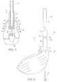
- FIG. 1is a side view of a portion of an exemplary golf club including an embodiment of the interchangeable shaft system of the present invention
- FIG. 2is an exploded view of the golf club of FIG. 1 ;
- FIG. 3is a cross-sectional view taken along line 3 - 3 , shown in FIG. 1 , of the golf club
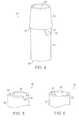
- FIG. 4is a perspective view of a shaft sleeve of the interchangeable shaft system
- FIG. 5is a perspective view of a proximal end portion of the hosel of the golf club of FIG. 1 ;
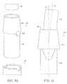
- FIG. 6is a perspective view of another embodiment of a proximal end portion of a hosel of a golf club having an interchangeable shaft system
- FIG. 7is a perspective view of another embodiment of the shaft sleeve of the interchangeable shaft system.
- FIG. 8is a perspective view of another embodiment of the shaft sleeve of the interchangeable shaft system.
- FIG. 9is a partial cross-sectional view of another embodiment of the shaft sleeve of the interchangeable shaft system.
- FIG. 10is an exploded view of a golf club including another embodiment of the interchangeable shaft system of the present invention.
- FIG. 11is a schematic of the connection between a shaft sleeve and a shaft of the interchangeable shaft system
- FIG. 12is side view of a portion of a golf club including another embodiment of the interchangeable shaft system of the present invention.
- FIG. 13is a partial exploded view of the golf club of FIG. 12 ;
- FIG. 14is a cross-sectional view taken along line 14 - 14 , shown in FIG. 12 , of the golf club.
- FIGS. 15-18are side views of various indicia that may be incorporated into a golf club including the interchangeable shaft system of the present invention.
- the present inventionis directed to an interchangeable shaft system for connecting the shaft of a golf club to a club head.
- a systemcan be utilized to provide for customized fitting of various shaft types to a club head and/or to provide adjustability between a shaft and a club head.
- a golf club incorporating an interchangeable shaft system 10 of the present inventiongenerally includes a shaft 12 , a shaft sleeve 14 , a club head 16 and a fastener 18 .
- Interchangeable shaft system 10may be used by club fitters to repeatedly change shaft 12 and club head 16 combinations during a fitting session. The system permits fitting accounts maximum fitting options with an assembly of parts that is easy to use.
- interchangeable shaft system 10may be semi-permanently fixed so that disassembly by the average consumer is prevented.
- interchangeable shaft system 10may be configured so that a consumer may manipulate the connection to replace shaft 12 or club head 16 and/or to provide adjustability between shaft 12 and club head 16 .
- the interchangeable shaft system of the present inventionis incorporated into a driver style golf club.
- the interchangeable shaft system of the present inventionmay be incorporated into any style of golf club.
- the interchangeable shaft systemmay be incorporated into putters, wedges, irons, hybrids and/or fairway wood styles of golf clubs.
- Club head 16generally includes a face 24 , a crown 25 , a sole 26 and a skirt 27 that are combined to form the generally hollow club head 16 .
- Club head 16also includes hosel 20 that is a structure providing for a secure attachment between shaft 12 and club head 16 during manufacture of the golf club.
- Shaft 12may be any shaft known in the art.
- shaft 12may be constructed of metallic and/or non-metallic materials and shaft may be hollow, solid or a combination of solid and hollow portions.
- interchangeable shaft system 10connects shaft 12 to club head 16 so that different shafts 12 can be selectively connected to different club heads 16 .
- Interchangeable shaft system 10generally includes shaft sleeve 14 that is coupled to shaft 12 and at least partially received within hosel 20 of club head 16 and fastener 18 that releasably couples sleeve 14 to club head 16 .
- a distal end portion 34 of shaft 12is received within a shaft bore 36 of sleeve 14 and is securely attached thereto.
- Shaft 12may be securely attached to sleeve 14 using any fastening method.
- attachment methodssuch as welding, ultrasonic welding, brazing, soldering, bonding, etc.
- Adhesivessuch as epoxies or other similar materials may be utilized to securely fasten shaft 12 and sleeve 14 .
- end portion 34is bonded within shaft bore 36 using an adhesive, such as epoxy.
- Sleeve 14is inserted into hosel 20 in a selected orientation that assures that alignment features included on sleeve 14 and hosel 20 are engaged when the interchangeable shaft system is assembled.
- the orientation of the alignment featuresprovides a desired relative position between shaft 12 and club head 16 .
- the engagement of the alignment featuresprovides an anti-rotation feature that prevents relative rotation between sleeve 14 and hosel 20 about the longitudinal axis of hosel 20 .
- Hosel 20is a generally tubular member that extends through crown 25 and at least a portion of club head 16 .
- Hosel 20defines a sleeve bore 30 that has a diameter selected so that a distal portion of sleeve 14 may be slidably received therein.
- the diameter of sleeve bore 30is selected so that there is minimal clearance between distal portion of sleeve 14 and hosel 20 to prevent relative lateral motion between sleeve 14 and hosel 20 .
- Sleeve bore 30terminates at a distal flange 31 which is located at a distal end of hosel 20 . It should be appreciated, however, that the flange may be located at any intermediate position between the proximal and distal ends of the hosel.
- a proximal end 28 of hosel 20is disposed outward from club head 16 at a location spaced from crown 25 and includes at least one hosel alignment feature that extends through at least a portion of the sidewall of hosel 20 .
- the hosel alignment featureprovides at least one discrete alignment orientation between club head 16 and shaft 12 in the assembled golf club.
- hosel 20includes alignment features in the form of a pair of notches 32 and each notch 32 extends through the sidewall of hosel 20 adjacent proximal end 28 , i.e., each notch 32 extends from sleeve bore 30 to the outer surface of proximal end 28 of hosel 20 .
- a proximal end portion 22 of a hosel 21may include notches 33 that extend only through a portion of the sidewall of hosel 21 .
- notches 33 of the present embodimentinclude a generally trapezoidal cross-section similar to the previously described embodiment, however, notches 33 extend radially from sleeve bore 29 through a portion of the sidewall of proximal portion 22 of hosel 21 and do not intersect the outer surface of hosel 21 .
- Such an embodimentmay be preferred when it is desired to hide the alignment features from a user.
- Notches 32are diametrically opposed from each other in proximal end 28 at spaced locations about the proximal end of the generally tubular hosel 20 . That configuration allows the combined shaft 12 and sleeve 14 to be coupled to club head 16 in two discrete positions rotated approximately 180° from each other.
- the hosel alignment featuresmay be located in any desired position adjacent proximal end 28 of hosel 20 to provide any desired orientation between sleeve 14 and hosel 20 .
- the present inventionincludes a pair of hosel alignment features, any number of hosel alignment features may be provided to provide any number of discrete orientations between shaft 12 and club head 16 . Still further, a single hosel alignment feature may be provided when a single discrete orientation between the shaft and club head is desired.
- Sleeve 14includes a distal body 38 , a proximal ferrule 40 and at least one sleeve alignment feature.
- the present embodimentincludes a pair of sleeve alignment features (e.g., tangs 42 ).
- Body 38is generally cylindrical and includes a proximal end that is coupled to a distal end of ferrule 40 .
- the length of shaft sleeve 14 and the diameter of shaft 12may be selected so that adequate surface area is provided for attachment to shaft 12 .
- Shaft sleeve 14 and shaft 12are configured to provide approximately 0.5-2.0 in 2 of bonding surface area. In an embodiment, shaft sleeve 14 and shaft are selected to provide approximately 1.2 in 2 of bonding surface area.
- shaft sleeve 14has a bonding length of approximately 1.1 inches to provide adequate bonding surface area on a shaft having a 0.335 inch diameter.
- body 38 and ferrule 40are coupled so that they form a single integrated component, but it should be appreciated that body 38 and ferrule 40 may be separate components.
- Tangs 42extend laterally outward beyond an outer surface of body 38 adjacent the interface between body 38 and ferrule 40 .
- the shape of tangs 42is selected to complement the shape of notches 32 so that relative rotation about the longitudinal axis of hosel 20 in either direction between sleeve 14 and hosel 20 is prevented when tangs 42 engage notches 32 .
- tangs 42have a generally trapezoidal cross-sectional shape and that trapezoidal shape is selected to complement and engage the trapezoidal shape of notches 32 .
- Tangs 42are configured so that they are tapered with the narrowest portion oriented toward the distal end of sleeve 14 and notches 32 are similarly tapered with the narrowest portion oriented toward sole 26 of club head 16 .
- outer surfaces of tangs 42are curved with a diameter that is substantially identical to the outer diameter of proximal end 28 of hosel 20 so that the outer surface of tangs 42 are substantially flush with the outer surface of hosel 20 in an assembled golf club.
- the outer surface of the tangs and the proximal end of the hoselneed not be flush if desired.
- notches 32 and tangs 42assure that there is a secure fit between sleeve 14 and hosel 20 when interchangeable shaft system 10 is assembled.
- the tapered side edges of tangs 42forcibly abut the tapered side walls of notches 32 to provide a secure fit that assures consistent and repeatable positioning of sleeve 14 relative to hosel 20 .
- the tapered surfacesalso prevent rotational play between sleeve 14 and hosel 20 resulting from manufacturing tolerances or wear.
- the hosel and sleeve alignment featuresmay have curved edges and side walls that engage during assembly to provide a similarly secure fit.
- the outer diameter of body 38is smaller than the outer diameter of the distal end of ferrule 40 so that a shoulder 46 is created at the interface between body 38 and ferrule 40 .
- body portion 38 of sleeveis inserted into sleeve bore 30 until shoulder 46 is disposed adjacent the top edge of hosel 20 .
- the size, taper and/or curvature of the hosel and sleeve alignment featuresare preferably selected so that there is a small amount of clearance between shoulder 46 and hosel 20 when the golf club is assembled.
- the size and taper of tangs 42 and notches 32are selected so that there is a small amount of clearance between the distal end surfaces of tangs 42 and the distal end surfaces of notches 32 . That clearance allows the relative position between sleeve 14 and hosel 20 to be easily controlled by manipulating the dimensions of the respective alignment features.
- the amount of clearance between shoulder 46 and hosel 20is visually imperceptible, or at least not easily noticeable, in the assembled golf club.
- the amount of clearancemay range from 0.005-0.030 inches.
- Sleeve 14 and hosel 20may be constructed from any metallic or non-metallic material, such as, for example, titanium, steel, aluminum, nylon, fiber reinforced polymer or polycarbonate. Furthermore, sleeve 14 and hosel 20 may be constructed from the same or different materials and as discussed further below each of sleeve 14 and hosel 20 may alternatively have multi-material construction. Additionally, sleeve 14 and/or hosel 20 may be constructed from a material that is a combination of both metallic and non-metallic material, such as a polymer infused or plated with metallic material. In an embodiment, hosel 20 is constructed of titanium and sleeve 14 is constructed from aluminum. Preferably, hosel 20 is formed as an integral part of club head 16 .
- a coating or surface treatmentmay also be provided on sleeve 14 and/or hosel 20 to prevent corrosion and/or to provide a desired aesthetic appearance.
- sleeve 14constructed from a first metallic material, such as aluminum
- hosel 20constructed from a second metallic material, such as titanium
- sleeve 14may be anodized to prevent galvanic corrosion.
- a non-metallic sleeve 14may be coated with nickel to provide the appearance of metallic construction.
- Fastener 18is securely fastened to club head 16 by fastener 18 to prevent disengagement of sleeve 14 from sleeve bore 30 .
- Fastener 18is primarily employed to prevent relative motion between sleeve 14 and club head 16 in a direction parallel to the longitudinal axis of hosel 20 .
- Fastener 18may be any type of fastener that restricts relative motion between sleeve 14 and hosel 20 .
- fastener 18is an elongate mechanical fastener, such as a machine screw that engages a threaded hole in sleeve 14 .
- Fastener 18 and sleeve 14are dimensioned to provide sufficient thread length to withstand the axial forces placed upon interchangeable shaft system 10 .
- fastener 18 and sleeve 14are dimensioned to provide 1 ⁇ 4 inch of threaded engagement.
- thread insertsmay be provided if desired to increase the strength of the threads.
- a thread insertsuch as Heli-coil thread inserts (a registered trademark of Emhart, Inc. of Newark, Del.) may be installed into sleeve 14 .
- hosel 20extends only partially through club head 16 .
- a separate fastener bore 50is provided that extends into club head 16 proximally from sole 26 and is generally coaxially aligned with hosel 20 .
- the proximal end of fastener bore 50terminates at a proximal flange 54 .
- Flange 54is generally annular and provides a bearing surface for a head portion of fastener 18 .
- a shank of fastener 18extends through flange 54 , across a gap 52 between fastener bore 50 and hosel 20 , through flange 31 and engages flange 44 of sleeve 14 .
- sleeve 14is drawn into hosel 20 .
- tangs 42 of sleeve 14are drawn into notches 32 of hosel 20 and the tapered side edges of tangs 42 forcibly abut the tapered side walls of notches 32 .
- the tapered interface between tangs 42 and notches 32assures that as fastener 18 is tightened in sleeve 14 , the fit between sleeve 14 and hosel 20 becomes progressively more secure and sleeve 14 travels to a predetermined and repeatable position within hosel 20 .
- hosel 20 and sleeve bore 30 in club head 16may be selected so that a desired length of shaft 12 and sleeve 14 are received therein.
- hosel 20extends only partially into club head 16 . It should, however, be appreciated that the hosel may extend through the entire club head so that it intersects the sole.
- a flange providing a bearing surface for the head of the fastenermay be located at any intermediate location within the hosel and a separate fastener bore need not be provided.
- the hosel alignment featuresare located adjacent proximal end 28 of hosel 20 and extend through at least a portion of the side wall of hosel 20 . Locating the hosel alignment features adjacent proximal end 28 of hosel 20 greatly simplifies manufacture of the hosel alignment features and club head 16 because the area is easily accessible.
- alignment features having precise tolerancesmay be incorporated into hosel 20 by simple machining processes and using common tools.
- a generally trapezoidal hosel alignment feature extending entirely through the sidewall of hosel 20such as notch 32
- hosel alignment features having tightly controlled dimensionsmay be easily constructed with any desired shape by using simple tooling and processes.
- the alignment featuresmay be positioned at any location around the circumference of sleeve 14 and hosel 20 .
- a pair of alignment featuresare disposed approximately 180° apart about the circumference of body 38 and hosel 20 (i.e., the alignment features are diametrically opposed) with one of the features being located adjacent face 24 of club head 16 . That orientation results in the alignment features being obscured from sight when a user places the club in the address position and views the club along a line of sight that is generally parallel to the longitudinal axis of shaft 12 . That orientation also allows the alignment features to be easily viewed by a user during adjustment by viewing club head 16 along a line of sight that is generally normal to face 24 .
- a locking mechanismmay be provided to prevent fastener 18 from disengaging from sleeve 14 .
- Any locking mechanismmay be employed.
- lock washersmay be provided between the head of fastener 18 and the adjacent bearing surface.
- a locking thread designsuch as a Spiralock locking internal thread form (a registered trademark of Detroit Tool Industries Corp. of Madison Heights, Mich.) may be incorporated into threaded bore 48 of flange 44 .
- a thread locking materialsuch as Loctite thread locking adhesive (a registered trademark of the Henkel Corp. of Gulph Mills, Pa.) may be applied to fastener 18 or threaded bore 48 .
- fastener 18may be provided with a locking feature such as a patch lock.
- a bonding material, such as epoxymay be applied to the head of fastener 18 at an interface with club head 16 after assembly.
- a retainer 56may be employed so that fastener 18 is retained within club head 16 when it is not engaged with sleeve 14 .
- Retainer 56is coupled to the shank of fastener 18 and located so that a flange is interposed between retainer 56 and the head of fastener 18 .
- Retainer 56is sized so that it is not able to pass through the through hole of the respective flange.
- Retainer 56may be a clip that is frictionally coupled to the shank of fastener 18 adjacent flange 31 of hosel 20 located so that flange 31 is interposed between retainer 56 and the head of fastener 18 .
- shaft sleeve 63includes a multi-piece construction that includes a body 65 , a pair of alignment features (e.g., tangs 67 ) and a ferrule 69 .
- tangs 67are integral with ferrule 69 , but body 65 is a separate component.
- Body 65is generally cylindrical and includes a proximal end that is located adjacent a distal end of ferrule 69 when assembled on a shaft.
- the proximal end of body 65includes notches 71 that are sized and shaped to complement the size and shape of tangs 67 .
- notches 71are preferably sized and shaped so that there are no gaps between the distal surface of ferrule 69 and the proximal end surface of body 65 or between the side surfaces of tangs 67 and the side surfaces of notches 71 .
- the thickness of tangs 67is selected so that when shaft sleeve 63 is assembled, portions of tangs 67 extend radially outward beyond the outer surface of body 65 . As a result, that portion of tangs 67 extending radially outward from body 65 is available to engage engagement features provided in the proximal end portion of the hosel of a golf club head as described above.
- Shaft sleeve 64includes a body 66 , a pair of alignment features (e.g., tangs 68 ) and a ferrule 70 .
- Tangs 68are integral with body 66 and ferrule 70 is separate from tangs 68 and body 66 .
- Body 66is generally cylindrical and includes a proximal end that is located adjacent a distal end of ferrule 70 when assembled on a shaft. Tangs 68 extend laterally outward from body 66 adjacent the proximal end of body 66 .
- Body 66 and ferrule 70may be constructed from any materials and they may be constructed from the same or different materials.
- body 66may be machined from a metallic material, such as aluminum, and ferrule 70 may be molded or machined from a non-metallic material, such as nylon.
- Different materialsmay be used to provide weight savings over an entirely metallic sleeve while still providing adequate structural qualities and bonding surface area. Additionally, different materials may be selected to provide desired aesthetic properties.
- the body of any embodiment of the shaft sleevemay further include weight reducing features if desired.
- shaded portion 72may include slots, depressions, through holes or any other feature that reduces the volume of material from which body 66 is constructed.
- the volume of body materialmay be reduced over any desired portion of the shaft sleeve body as long as sufficient surface area is provided for adequately coupling the shaft with the shaft sleeve.
- shaft sleeve 74includes a body 76 , a ferrule 78 and tangs 80 extending laterally outward from body 76 .
- Shaft sleeve 74is illustrative of a single piece construction of the shaft sleeve that is molded from a non-metallic material, such as, for example, nylon, fiber reinforced polymer or polycarbonate. Because of that construction, shaft sleeve 74 also includes a threaded insert 82 that is molded into a distal flange 84 of sleeve 74 . Threaded insert 82 may include features that allow the insert to be securely molded in place, such as knurling and/or one or more ribs or flanges.
- FIG. 10illustrates an exploded view of a portion of another embodiment of a golf club including an interchangeable shaft system. Similar to the previously described embodiments, the golf club includes a shaft 90 that is coupled to a hosel 92 of a club head by an interchangeable shaft system that includes a shaft sleeve 94 .
- sleeve 94utilizes a multi-piece construction.
- Sleeve 94includes body 96 that is integral with ferrule 98 and sleeve alignment features that are formed by a separate pin 100 that is coupled to body 96 and ferrule 98 .
- Pin 100extends diametrically across the interface of body 96 and ferrule 98 and is securely coupled to body 96 and ferrule 98 .
- the length of pin 100is selected so that the ends of pin 100 extend laterally outward beyond the outer surface of body 96 .
- each end of pin 100extends laterally outward of body 96 by a distance corresponding to the thickness of the side wall of hosel 92 of the club head so that the ends of pin 100 are generally flush with the outer surface of hosel 92 .
- pin 100is illustrated as a generally cylindrical member, it should be appreciated that it may have any desired cross-sectional shape and hosel 92 may include hosel alignment features having any complementary shape.
- pin 100may be a key having any polygonal cross-sectional shape, such as a triangle, trapezoid, square, rectangle, diamond, etc.
- the interchangeable shaft system of the present inventionmay be configured to provide adjustability for the angular attributes of an assembled golf club, including face angle, lie and loft.
- the configuration of the hosel and sleeve alignment featuresprovide discreet orientations of the sleeve relative to the hosel.
- the shaftmay be mounted to the sleeve so that the shaft is not coaxial with the sleeve. That misalignment allows each of the discreet orientations of the sleeve relative to the hosel to correspond to a different orientation of the shaft to the club head.
- the angular attributes of the assembled golf clubmay be adjustable by changing the orientation of the shaft sleeve relative to the hosel.
- a shaft 102is mounted to a sleeve 104 so that an angular attribute, or select combinations of angular attributes, may be adjusted between at least a first configuration and a second configuration.
- a longitudinal axis A of a shaft bore 106 of sleeve 104may be rotated relative to a longitudinal axis B of a body 108 and a ferrule 110 of sleeve 104 .
- the longitudinal axis of shaft 102is coaxial with longitudinal axis A of sleeve bore 106 .
- the direction of the rotational offset between axis A and axis Bis positioned relative to the hosel and sleeve alignment features so that rotation of the sleeve within the hosel between the two positions alters the club face angle.
- the sleevemay be coupled to the hosel in a first position corresponding to a first configuration wherein the club face is opened.
- the sleevemay then be coupled to the hosel in a second position, e.g., the sleeve is rotated 180° from the first position, which corresponds to a second configuration wherein the club face is closed.
- shaft 102 and sleeve 104may be coupled so that more than two configurations are provided.
- the sleeve and accompanying golf club headmay be configured so that there are more than two relative configurations thereby providing adjustability in multiple combinations of angular attributes.
- a golf club including the interchangeable shaft system of the present inventionmay be adjustable for overall length by providing a plurality of hosel alignment features having different depths.
- a pair of hosel alignment features having different depths from the proximal end of the hoselare provided in a golf club head.
- a shaft sleeveis provided that includes a single sleeve alignment feature that is sized and shaped to engage either of the hosel alignment features.
- the sleeve alignment featureis engaged with the deeper hosel alignment feature, which results in the sleeve being drawn into the hosel to a first depth and thereby providing a first overall golf club length.
- the sleeve alignment featureis engaged with the shallower hosel alignment feature, which results in the sleeve being drawn into the hosel to a second depth that is less than the first depth and thereby providing a second overall golf club length that is less than the first.
- Interchangeable shaft system 120is similar to the previously described embodiments in that it generally includes a shaft sleeve 122 that is coupled to a shaft 124 and a fastener 126 that retains sleeve 122 within a hosel 128 of a club head 130 .
- fastener 126is integral with a ferrule 132 .
- Sleeve 122includes a body 134 and alignment features (e.g., tangs 136 ).
- Sleeve 122includes a separate ferrule 132 .
- body 134 of sleeve 122is at least partially received within a sleeve bore 138 of hosel 128 .
- Body 134is oriented so that tangs 136 engage complementary alignment features of hosel 128 (e.g., notches 140 ).
- Fastener 126is integrated into and forms a portion of ferrule 132 .
- fastener 126is a distal portion of ferrule 132 that is configured to mechanically engage a portion of hosel 128 .
- fastener 126is a portion of ferrule 132 that includes a threaded internal 144 surface and is configured to threadably engage a threaded outer surface 146 of hosel 128 .
- Ferrule 132also includes a bearing surface 142 .
- Bearing surface 142forcibly abuts a proximal end surface of sleeve 122 when interchangeable shaft system 120 is assembled.
- shaft 124is inserted through ferrule 132 so that ferrule 132 is able to slide on and rotate relative to shaft 124 .
- sleeve 122is coupled to the distal end of shaft 124 .
- the dimensions of sleeve 122are selected so that ferrule 132 is prevented from sliding past sleeve 122 toward the distal end of shaft 124 .
- Sleeve 122is then inserted into sleeve bore 138 so that tangs 136 engage notches 140 with sleeve 122 in a desired rotational orientation. Finally, ferrule 132 is slid along shaft 124 until bearing surface 142 abuts sleeve 122 and fastener 126 is threaded on hosel 128 .
- Indiciamay be provided to clearly indicate the configuration of the shaft relative to the club head in the assembled golf club.
- the shaftmay be coupled to the shaft sleeve so that the club can be assembled in a first or second configuration.
- Indiciamay be placed on the shaft sleeve and/or the hosel to indicate the assembled configuration.
- the indiciamay be positioned so that they are visible only during assembly or during and after assembly, as desired.
- any form of indiciamay be provided.
- the indiciamay be engraved, raised or painted and they may be one or more letters, numbers, symbols, dots and/or other markings that differentiate the available configurations of the golf club.
- the indiciamay be included on any portion of the club head, shaft sleeve, or shaft of the assembled golf club.
- indiciaare provided on or adjacent the sleeve and/or hosel alignment features.
- the indiciamay include letters corresponding to the configuration of the golf club.
- indicium 150is an “O” that is located on a sleeve alignment feature and corresponds to an opened face angle configuration of the golf club.
- indicium 152in the form of a letter “C,” is provided on another sleeve alignment feature that corresponds to a closed face angle club configuration.
- the hosel and shaft sleeve alignment featurese.g., notches 32 and tangs 42
- indiciaare positioned to reduce the visibility of those features during use.
- tangs 42are located so that they are diametrically opposed from each other about the circumference of hosel 20 on an axis that is generally normal to a plane defined by face 24 of club head 16 . As a result, tangs 42 are visible along a line of sight generally normal to face 24 of club head 16 .
- the tangs 42are obscured from view, i.e., the alignment features are not visible along an axis generally parallel to the longitudinal axis of the shaft, and the golf club has an appearance of a golf club lacking the interchangeable shaft system when the golf club head is at address.
- indicia 154 and 156include both letters and symbols (e.g., “L+” and “L ⁇ ”). Combinations of letters, symbols and/or numbers may be used to clearly indicate the configuration of the assembled golf club. In the present example, indicia 154 and 156 are particularly well-suited to indicate increased and reduced lie or loft angle of the club head, respectively. Additionally, indicium 158 may be provided to indicate to the user which of the indicia included on sleeve 14 corresponds to the assembled configuration of the golf club.
- the interchangeable shaft system of the present inventionprovides advantages over conventional methods of club fitting.
- a useris required to make test swings with a plurality of non-adjustable samples of a single golf club.
- a conventional fitting cart, or baggenerally includes a plurality of sample 6-Irons having multiple configurations. The user is required to try many of those sample clubs to try to determine which sample includes the most appropriate configuration.
- each sample clubis not adjustable, differences between the individual components of the plurality of sample clubs introduce additional variables into the fitting process and the fitting cart, or bag, is required to include many separate and complete sample clubs.
- a method of fitting golf clubs to a user utilizing the interchangeable shaft system of the present inventionremoves many of those additional variables and reduces the number of required complete sample clubs by minimizing the number of components required for the fitting process.
- the interchangeable shaft systemallows a single club head to be used throughout the fitting process with different shafts and/or by altering the orientation of a single shaft relative to the club head.
- the systemalso allows different club heads to be utilized with a single shaft if desired.
- the methodincludes providing a golf club including the interchangeable shaft system of the present invention in a first configuration.
- the userswings the golf club while it is in the first configuration.
- the user's swingis analyzed and the interchangeable shaft system of the golf club is disassembled and re-assembled into a second configuration.
- the userthen swings the golf club while it is in the second configuration and the user's swing is analyzed.
- These stepsmay be repeated with any number of golf club configurations.
- the proper club configuration for the useris determined based on the analyses of the user's swings.
- the combined shaft and sleeve that was included in the golf club in the first configurationmay be re-oriented relative to the club head to provide a change in one, or combinations, of the angular attributes of the golf club.
- the shaft and sleeve combinationmay be substituted and a different shaft and sleeve attached to the club head.
- a substitution of the shaft and sleeve combinationmay be desired to change angular attributes and/or any other physical attribute of the golf club, such as shaft flexibility, shaft length, grip feel, etc.
- driver-type clubsany type of golf club can utilize the inventive interchangeable shaft system.
- the interchangeable shaft systemcan be used with non-golf equipment, such as fishing poles, aiming sights for firearms, plumbing, etc.
Landscapes
- Health & Medical Sciences (AREA)
- General Health & Medical Sciences (AREA)
- Physical Education & Sports Medicine (AREA)
- Life Sciences & Earth Sciences (AREA)
- Engineering & Computer Science (AREA)
- Wood Science & Technology (AREA)
- Golf Clubs (AREA)
Abstract
Description
Claims (18)
Priority Applications (2)
| Application Number | Priority Date | Filing Date | Title |
|---|---|---|---|
| US12/762,656US7980959B2 (en) | 2008-01-31 | 2010-04-19 | Interchangeable shaft system |
| US13/185,075US8360897B2 (en) | 2008-01-31 | 2011-07-18 | Interchangeable shaft system |
Applications Claiming Priority (2)
| Application Number | Priority Date | Filing Date | Title |
|---|---|---|---|
| US12/023,402US7699717B2 (en) | 2008-01-31 | 2008-01-31 | Interchangeable shaft system |
| US12/762,656US7980959B2 (en) | 2008-01-31 | 2010-04-19 | Interchangeable shaft system |
Related Parent Applications (1)
| Application Number | Title | Priority Date | Filing Date |
|---|---|---|---|
| US12/023,402ContinuationUS7699717B2 (en) | 2007-12-18 | 2008-01-31 | Interchangeable shaft system |
Related Child Applications (1)
| Application Number | Title | Priority Date | Filing Date |
|---|---|---|---|
| US13/185,075ContinuationUS8360897B2 (en) | 2008-01-31 | 2011-07-18 | Interchangeable shaft system |
Publications (2)
| Publication Number | Publication Date |
|---|---|
| US20100203981A1 US20100203981A1 (en) | 2010-08-12 |
| US7980959B2true US7980959B2 (en) | 2011-07-19 |
Family
ID=40932258
Family Applications (3)
| Application Number | Title | Priority Date | Filing Date |
|---|---|---|---|
| US12/023,402Active2028-02-09US7699717B2 (en) | 2007-12-18 | 2008-01-31 | Interchangeable shaft system |
| US12/762,656ActiveUS7980959B2 (en) | 2008-01-31 | 2010-04-19 | Interchangeable shaft system |
| US13/185,075ActiveUS8360897B2 (en) | 2008-01-31 | 2011-07-18 | Interchangeable shaft system |
Family Applications Before (1)
| Application Number | Title | Priority Date | Filing Date |
|---|---|---|---|
| US12/023,402Active2028-02-09US7699717B2 (en) | 2007-12-18 | 2008-01-31 | Interchangeable shaft system |
Family Applications After (1)
| Application Number | Title | Priority Date | Filing Date |
|---|---|---|---|
| US13/185,075ActiveUS8360897B2 (en) | 2008-01-31 | 2011-07-18 | Interchangeable shaft system |
Country Status (1)
| Country | Link |
|---|---|
| US (3) | US7699717B2 (en) |
Cited By (37)
| Publication number | Priority date | Publication date | Assignee | Title |
|---|---|---|---|---|
| US20110088244A1 (en)* | 2008-07-22 | 2011-04-21 | Nike, Inc. | Releasable and interchangeable connections for golf club heads and shafts |
| US20110111881A1 (en)* | 2009-02-05 | 2011-05-12 | Nike, Inc. | Releasable And Interchangeable Connections For Golf Club Heads And Shafts |
| US8182357B2 (en) | 2007-09-10 | 2012-05-22 | Nike, Inc. | Adjustable connector |
| US8419567B2 (en) | 2011-08-31 | 2013-04-16 | Karsten Manufacturing Corporation | Golf coupling mechanisms and related methods |
| US8449404B2 (en) | 2009-02-05 | 2013-05-28 | Nike, Inc. | Releasable and interchangeable connections for golf club heads and shafts |
| USD687504S1 (en) | 2012-03-24 | 2013-08-06 | Karsten Manufacturing Corporation | Golf club hosel sleeve |
| US8517856B2 (en) | 2007-12-18 | 2013-08-27 | Acushnet Company | Interchangeable shaft system |
| US8523700B2 (en) | 2009-07-24 | 2013-09-03 | Nike, Inc. | Releasable and interchangeable connections for golf club heads and shafts |
| US8616995B2 (en) | 2007-07-06 | 2013-12-31 | Nike, Inc. | Releasable and interchangeable connections for golf club heads and shafts |
| US8801538B2 (en) | 2007-12-18 | 2014-08-12 | Acushnet Company | Interchangeable shaft system |
| US8926447B2 (en) | 2011-08-31 | 2015-01-06 | Karsten Manufacturing Corporation | Golf coupling mechanisms and related methods |
| US8932147B2 (en) | 2011-08-31 | 2015-01-13 | Karsten Maunfacturing Corporation | Golf coupling mechanisms and related methods |
| US8961330B2 (en) | 2007-12-18 | 2015-02-24 | Acushnet Company | Interchangeable shaft system |
| USD723121S1 (en) | 2013-10-14 | 2015-02-24 | Karsten Manufacturing Corporation | Golf club hosel insert |
| US8961329B2 (en) | 2009-03-16 | 2015-02-24 | Nike, Inc. | Releasable and interchangeable connections for golf club heads and shafts |
| US9144719B1 (en) | 2014-06-18 | 2015-09-29 | Wilson Sporting Goods Co. | Golf club adjustable hosel assembly |
| US9144720B1 (en) | 2014-06-18 | 2015-09-29 | Wilson Sporting Goods Co. | Golf club adjustable hosel assembly |
| US9168426B2 (en) | 2013-03-12 | 2015-10-27 | Karsten Manufacturing Corporation | Golf clubs with hosel inserts and methods of manufacturing golf clubs with hosel inserts |
| US9327170B2 (en) | 2011-08-31 | 2016-05-03 | Karsten Manufacturing Corporation | Golf clubs with hosel inserts and related methods |
| USD757194S1 (en) | 2012-03-24 | 2016-05-24 | Karsten Manufacturing Corporation | Golf club hosel insert |
| US9358429B2 (en) | 2014-06-18 | 2016-06-07 | Wilson Sporting Goods Co. | Golf club adjustable hosel assembly |
| US9403067B2 (en) | 2007-12-18 | 2016-08-02 | Acushnet Company | Interchangeable shaft system |
| US20160279487A1 (en)* | 2007-12-18 | 2016-09-29 | Acushnet Company | Interchangeable shaft system |
| USD773576S1 (en) | 2014-11-18 | 2016-12-06 | Parsons Xtreme Golf, LLC | Golf club hosel sleeve |
| US20170157471A1 (en)* | 2015-12-04 | 2017-06-08 | Dunlop Sports Co. Ltd. | Golf club |
| US9764203B2 (en) | 2007-12-18 | 2017-09-19 | Acushnet Company | Interchangeable shaft system |
| US9868035B2 (en) | 2011-08-31 | 2018-01-16 | Karsten Manufacturing Corporation | Golf clubs with hosel inserts and related methods |
| US10004952B2 (en) | 2011-08-31 | 2018-06-26 | Karsten Manufacturing Corporation | Golf coupling mechanisms and related methods |
| US10188913B2 (en) | 2007-12-18 | 2019-01-29 | Acushnet Company | Interchangeable shaft system |
| US10328318B2 (en) | 2017-06-02 | 2019-06-25 | Sumitomo Rubber Industries, Ltd. | Golf club |
| US10369426B2 (en) | 2016-12-28 | 2019-08-06 | Sumitomo Rubber Industries, Ltd. | Golf club |
| USD872203S1 (en) | 2018-04-17 | 2020-01-07 | Karsten Manufacturing Corporation | Shaft sleeve |
| US10806975B2 (en) | 2017-12-01 | 2020-10-20 | Sumitomo Rubber Industries, Ltd. | Golf club |
| US10994184B1 (en)* | 2019-12-12 | 2021-05-04 | Speed Ring Golf Llc | Golf swing speed trainer |
| US11413507B2 (en) | 2017-12-19 | 2022-08-16 | Karsten Manufacturing Corporation | Golf club alternative fitting system |
| USD973808S1 (en) | 2020-08-11 | 2022-12-27 | Parsons Xtreme Golf, LLC | Golf club head |
| US12151147B2 (en) | 2021-09-21 | 2024-11-26 | Taylor Made Golf Company, Inc. | Golf club fitting systems |
Families Citing this family (48)
| Publication number | Priority date | Publication date | Assignee | Title |
|---|---|---|---|---|
| US8758153B2 (en) | 2009-12-23 | 2014-06-24 | Taylor Made Golf Company, Inc. | Golf club head |
| US8303431B2 (en) | 2008-05-16 | 2012-11-06 | Taylor Made Golf Company, Inc. | Golf club |
| US8337319B2 (en)* | 2009-12-23 | 2012-12-25 | Taylor Made Golf Company, Inc. | Golf club |
| US7887431B2 (en)* | 2008-05-16 | 2011-02-15 | Taylor Made Golf Company, Inc. | Golf club |
| US8622847B2 (en)* | 2008-05-16 | 2014-01-07 | Taylor Made Golf Company, Inc. | Golf club |
| US20100261543A1 (en)* | 2007-04-13 | 2010-10-14 | Breier Joshua G | Interchangeable shaft and club head connection system |
| US9757627B2 (en) | 2007-12-18 | 2017-09-12 | Acushnet Company | Interchangeable shaft system |
| US7874934B2 (en)* | 2008-01-31 | 2011-01-25 | Acushnet Company | Interchangeable shaft system |
| US7699717B2 (en) | 2008-01-31 | 2010-04-20 | Acushnet Company | Interchangeable shaft system |
| US8727905B2 (en) | 2007-12-18 | 2014-05-20 | Acushnet Company | Interchangeable shaft system |
| US8235835B2 (en)* | 2008-01-31 | 2012-08-07 | Acushnet Company | Interchangeable shaft system |
| US9033821B2 (en)* | 2008-05-16 | 2015-05-19 | Taylor Made Golf Company, Inc. | Golf clubs |
| US9604118B2 (en) | 2008-10-09 | 2017-03-28 | Golf Impact, Llc | Golf club distributed impact sensor system for detecting impact of a golf ball with a club face |
| US20120046119A1 (en)* | 2008-10-09 | 2012-02-23 | Golf Impact Llc | Golf Swing Measurement and Analysis System |
| US8303429B2 (en) | 2009-01-27 | 2012-11-06 | Callaway Golf Company | Golf club with stable face angle |
| US20100197423A1 (en)* | 2009-02-05 | 2010-08-05 | Nike, Inc. | Releasable and interchangeable connections for golf club heads and shafts |
| US7934999B2 (en)* | 2009-05-18 | 2011-05-03 | Callaway Golf Company | Wood-type golf club head with adjustable sole contour |
| US8202173B2 (en)* | 2009-08-13 | 2012-06-19 | Nike, Inc. | Angled connection for golf club heads and shafts |
| US20110165960A1 (en)* | 2010-01-04 | 2011-07-07 | Sports Leisure - Ben Parks, Joint Venture | Weighting Ferrule for Golf Club |
| JP5814677B2 (en)* | 2010-09-17 | 2015-11-17 | ダンロップスポーツ株式会社 | Golf club |
| US9333400B2 (en) | 2010-12-07 | 2016-05-10 | Taylor Made Golf Company, Inc. | Golf club set providing improved distance gapping adjustability |
| US8382607B2 (en) | 2010-12-07 | 2013-02-26 | Taylor Made Golf Company, Inc | Length adjustment system for joining a golf club head to a shaft |
| JP2012152331A (en)* | 2011-01-25 | 2012-08-16 | Bridgestone Sports Co Ltd | Golf club, method for changing shaft insertion depth and shaft replacement method |
| US20130045816A1 (en)* | 2011-08-19 | 2013-02-21 | Cobra Golf Incorporated | Golf club grip |
| WO2013028885A2 (en) | 2011-08-23 | 2013-02-28 | Nike International Ltd. | Releasable and interchangeable connections for golf club heads and shafts |
| US9050507B2 (en) | 2011-08-23 | 2015-06-09 | Nike, Inc. | Releasable and interchangeable connections for golf club heads and shafts |
| US11554296B2 (en) | 2011-08-31 | 2023-01-17 | Karsten Manufacturing Corporation | Golf club heads with golf coupling mechanisms |
| US9192823B2 (en) | 2011-08-31 | 2015-11-24 | Karsten Manufacturing Corporation | Golf coupling mechanisms and related methods |
| US11607590B2 (en) | 2011-08-31 | 2023-03-21 | Karsten Manufacturing Corporation | Golf club heads with hosel inserts and related methods |
| US9114294B2 (en) | 2012-02-28 | 2015-08-25 | Cobra Golf Incorporated | Distance gapping golf club set with dual-range club |
| US9114292B2 (en) | 2012-02-28 | 2015-08-25 | Cobra Golf Incorporated | Golf club head with stablizing sole |
| US8517850B1 (en) | 2012-12-11 | 2013-08-27 | Cobra Golf Incorporated | Golf club grip with device housing |
| USD682965S1 (en) | 2012-06-06 | 2013-05-21 | Callaway Golf Company | Golf club hosel piece |
| USD682378S1 (en) | 2012-06-19 | 2013-05-14 | Callaway Golf Company | Golf club shaft sleeve |
| US20140221120A1 (en)* | 2012-08-07 | 2014-08-07 | Dunlop Sports Co. Ltd. | Systems and methods for fitting golf clubs to golfers |
| US9737775B2 (en) | 2012-08-07 | 2017-08-22 | Dunlop Sports Co. Ltd. | Systems and methods for fitting golf clubs |
| KR101630750B1 (en)* | 2012-10-31 | 2016-06-15 | 나이키 이노베이트 씨.브이. | Releasable and interchangeable connections for golf club heads and shafts |
| USD697155S1 (en) | 2012-11-15 | 2014-01-07 | Taylor Made Golf Company, Inc. | Golf club head |
| USD697156S1 (en)* | 2013-02-04 | 2014-01-07 | Callaway Golf Company | Golf club hosel piece |
| US9216331B2 (en) | 2013-03-14 | 2015-12-22 | Taylor Made Golf Company, Inc. | Golf club head with adjustable sole |
| US9861864B2 (en) | 2013-11-27 | 2018-01-09 | Taylor Made Golf Company, Inc. | Golf club |
| US9839817B1 (en) | 2014-04-23 | 2017-12-12 | Taylor Made Golf Company, Inc. | Golf club |
| SG11201707894QA (en)* | 2015-04-17 | 2017-11-29 | Best Swing One Llc | Universal swing training apparatus |
| JP6822072B2 (en)* | 2016-11-02 | 2021-01-27 | 住友ゴム工業株式会社 | Golf club |
| USD849166S1 (en) | 2017-12-07 | 2019-05-21 | Ssg International, Llc | Golf putter grip |
| US10099101B1 (en) | 2017-12-07 | 2018-10-16 | Ssg International, Llc | Golf club grip with sensor housing |
| USD852306S1 (en)* | 2017-12-27 | 2019-06-25 | Phillip Lapuz | Lie adaptor |
| USD863480S1 (en)* | 2018-02-08 | 2019-10-15 | Volf (Shenzhen) Sports Products Co., Ltd | Universal golf shaft adapter |
Citations (25)
| Publication number | Priority date | Publication date | Assignee | Title |
|---|---|---|---|---|
| US1623523A (en)* | 1926-06-18 | 1927-04-05 | Lester L Bourke | Golf club |
| US2051961A (en) | 1935-09-30 | 1936-08-25 | Daniel T Mears | Golf club |
| US3170691A (en) | 1962-07-23 | 1965-02-23 | Frank C Pritchard | Golf club shaft and hosel connector |
| US3524646A (en) | 1967-06-08 | 1970-08-18 | Harold P Wheeler | Golf club assembly |
| US3685135A (en) | 1969-03-04 | 1972-08-22 | Ben Sayers Ltd | Method of fitting a golf club shaft to a head |
| US4664382A (en) | 1986-01-13 | 1987-05-12 | Global Golf Incorporated | Compact portable golf club set and carrying bag |
| US4852782A (en) | 1986-01-17 | 1989-08-01 | Wu Ko Lee | Equipment for playing golf |
| US4943059A (en) | 1987-06-16 | 1990-07-24 | Salomon, S.A. | Golf club having removable head |
| US4948132A (en) | 1986-11-06 | 1990-08-14 | Wharton Norman W | Golf club |
| US5039098A (en) | 1988-03-11 | 1991-08-13 | Pelz David T | Golf club having an aligning and quick connect-disconnect coupling between the golf club shaft and club head |
| EP0535848A1 (en) | 1991-09-25 | 1993-04-07 | Kawasaki, Atsushi | Golf club with interchangeable heads |
| US5433442A (en) | 1994-03-14 | 1995-07-18 | Walker; Brian S. | Golf clubs with quick release heads |
| US5722901A (en) | 1997-02-11 | 1998-03-03 | Barron; John R. | Releasable fastening structure for trial golf club shafts and heads |
| US5951411A (en) | 1998-01-05 | 1999-09-14 | Zevo Golf Co., Inc. | Hosel coupling assembly and method of using same |
| US20010007835A1 (en) | 1998-12-24 | 2001-07-12 | Baron George Alfred | Modular golf club system and method |
| US6547673B2 (en) | 1999-11-23 | 2003-04-15 | Gary Roark | Interchangeable golf club head and adjustable handle system |
| US20040018887A1 (en)* | 2002-07-24 | 2004-01-29 | Burrows Bruce D. | Temporary golf club shaft-component connection |
| US7083529B2 (en) | 2004-11-17 | 2006-08-01 | Callaway Golf Company | Golf club with interchangeable head-shaft connections |
| US20060281575A1 (en) | 2004-11-17 | 2006-12-14 | Alan Hocknell | Golf Club with Interchangeable Head-Shaft Connection |
| US20060287125A1 (en) | 2004-11-17 | 2006-12-21 | Alan Hocknell | Golf Club with Interchangeable Head-Shaft Connection |
| US20070117645A1 (en)* | 2005-11-21 | 2007-05-24 | Nakashima Golf, Inc. | Golf club and kit having interchangeable heads and shafts |
| US7300359B2 (en) | 2004-11-17 | 2007-11-27 | Callaway Golf Company | Golf club with interchangeable head-shaft connection |
| US20080280693A1 (en)* | 2005-08-22 | 2008-11-13 | Dong Hua Chai | Golf Club, Club Head and Body of the Club Head |
| US20080293510A1 (en)* | 2007-05-21 | 2008-11-27 | Sri Sports Limited | Golf club |
| US20090062029A1 (en)* | 2007-08-28 | 2009-03-05 | Nike, Inc. | Releasable and Interchangeable Connections for Golf Club Heads and Shafts |
Family Cites Families (105)
| Publication number | Priority date | Publication date | Assignee | Title |
|---|---|---|---|---|
| US782955A (en)* | 1904-10-12 | 1905-02-21 | Albert L Emens | Golf-club. |
| US1352918A (en) | 1920-02-21 | 1920-09-14 | William L Rohbock | Fastening device |
| US1540559A (en) | 1924-10-20 | 1925-06-02 | John J Murphy | Golf club |
| US1918583A (en)* | 1932-04-08 | 1933-07-18 | James Heddon S Sons | Fishing rod |
| US2020679A (en) | 1933-08-19 | 1935-11-12 | Clifton Ltd | Golf club |
| US2027452A (en) | 1934-05-10 | 1936-01-14 | Rusing Gunnar | Golf club |
| US2067556A (en) | 1935-10-29 | 1937-01-12 | William L Wettlaufer | Golf club |
| US2146321A (en) | 1937-06-22 | 1939-02-07 | William L Wettlaufer | Golf club |
| US2219670A (en) | 1939-01-25 | 1940-10-29 | William L Wettlaufer | Golf club |
| US2326495A (en) | 1940-10-22 | 1943-08-10 | Remo Aiazzone | Golf club |
| US2361415A (en) | 1943-06-17 | 1944-10-31 | Milton B Reach | Golf club |
| US2425808A (en) | 1944-11-14 | 1947-08-19 | Jakosky John Jay | Golf club |
| GB751323A (en) | 1954-08-17 | 1956-06-27 | Jones Robert | Improvements in golf clubs |
| US2770161A (en) | 1954-09-23 | 1956-11-13 | Charles E Schutte | Semi-spherical compensating washer |
| US2882053A (en) | 1955-12-19 | 1959-04-14 | Lorthiois Michel | Game-playing clubs |
| US2962286A (en) | 1956-11-28 | 1960-11-29 | Rodger D Brouwer | Universal golf club |
| US3087371A (en) | 1958-05-19 | 1963-04-30 | Orner Harry | Lock screw assembly incorporating stress indicator means |
| US3422721A (en) | 1966-08-22 | 1969-01-21 | John L Yonkers | Self-aligning and sealing member |
| US3595577A (en) | 1968-07-24 | 1971-07-27 | William R Hodge | Golf club |
| US3625517A (en) | 1969-11-10 | 1971-12-07 | John E Durnack | Golf putter with center of mass aligned with shaft axis |
| US3788185A (en) | 1972-02-01 | 1974-01-29 | Elco Industries Inc | Controlled-drive sealing fastener |
| US3810631A (en) | 1972-07-24 | 1974-05-14 | Con Sole Golf Corp | Golf club head of the iron type having a concave sole |
| US3840231A (en) | 1973-02-02 | 1974-10-08 | D Moore | Golf club having adjustable head means |
| US4253666A (en)* | 1978-03-20 | 1981-03-03 | William Murphy | Personal golf set for par-3 course |
| US4222567A (en) | 1978-10-10 | 1980-09-16 | The John Rouzee Green Co. | Golf club with loft angle markings |
| US4362449A (en) | 1979-11-30 | 1982-12-07 | Maclean-Fogg Company | Fastener assemblies |
| GB8716694D0 (en) | 1987-07-15 | 1987-08-19 | Petron Golf Equipment Ltd | Changing lie & face angle of golf club |
| JPH0614790Y2 (en) | 1987-07-24 | 1994-04-20 | 国雄 山田 | Head attachment device for golf club |
| FR2630655A1 (en) | 1988-05-02 | 1989-11-03 | Salomon Sa | METHOD OF ASSEMBLING A GOLF CLUB HANDLE AND HEAD WITH POSSIBILITY OF CHANGING THE LENGTH ANGLE OF THE HANDLE AND GOLF CLUB ASSEMBLED THEREBY |
| US4958834A (en)* | 1988-05-16 | 1990-09-25 | Colbert Robert E | Golf club assembly |
| JP2519150Y2 (en) | 1989-08-04 | 1996-12-04 | 有限会社竹内幹雄デザイン事務所 | Golf club grip angle adjustment sign |
| FR2654354A1 (en) | 1989-11-14 | 1991-05-17 | Salomon Sa | DEVICE FOR FIXING A HEAD OF A GOLF CLUB ON A SLEEVE. |
| US5133553A (en) | 1991-02-14 | 1992-07-28 | Divnick Stevan M | Adjustable golf club |
| US5326206A (en) | 1993-04-19 | 1994-07-05 | Northrop Corporation | Method for compensating for bolt hole misalignment and bolt assemblies therefor |
| US5527034A (en) | 1993-11-30 | 1996-06-18 | Goldwin Golf U.S.A., Inc. | Golf club and method of manufacture |
| US5538245A (en) | 1995-06-23 | 1996-07-23 | Moore; Donald D. | Golf club with adjustable head |
| TW417496U (en) | 1995-07-14 | 2001-01-01 | Emhart Inc | Device for coupling golf club head to shaft and golf club assembly thereof |
| US5588921A (en) | 1995-09-27 | 1996-12-31 | Parsick; Keith | Golf club |
| US6050903A (en) | 1996-03-11 | 2000-04-18 | Lake; Connie | Golf club with improved coupling between head and shaft |
| US5885170A (en) | 1996-03-12 | 1999-03-23 | Kabushiki Kaisha Endo Seisakusho | Iron-type golf club head production method therefor |
| US5634857A (en) | 1996-05-13 | 1997-06-03 | Bradshaw; Richard L. | Golf club having angularly adjustable shaft |
| WO1997045172A1 (en) | 1996-05-31 | 1997-12-04 | Tidymake Limited | A golf club |
| US6251028B1 (en) | 1996-08-19 | 2001-06-26 | Al Jackson | Golf club having a head with enlarged hosel and curved sole plate |
| US5839973A (en) | 1996-08-19 | 1998-11-24 | Jackson; Al | Golf club head with enlarged hosel |
| US5924938A (en) | 1997-07-25 | 1999-07-20 | Hines; James L. R. | Golf putter with movable shaft connection |
| US5851155A (en) | 1997-09-04 | 1998-12-22 | Zevo Golf Co., Inc. | Hosel construction and method of making the same |
| US6170691B1 (en)* | 1997-10-02 | 2001-01-09 | M & M Industries, Inc. | Open-head container and lid assembly |
| US5906549A (en) | 1997-12-11 | 1999-05-25 | Karsten Manufacturing Corporation | Golf club with different shaft orientations and method of making same |
| US6634958B1 (en) | 1998-01-22 | 2003-10-21 | Daiwa Seiko, Inc. | Golf club |
| US6669573B2 (en) | 1998-05-22 | 2003-12-30 | Golfsmith Licensing, L.L.C. | Hosel construction and method of making same |
| US5976028A (en)* | 1998-06-22 | 1999-11-02 | Ciccarello; Carl | Golf club spine finder and method |
| JP2000042151A (en)* | 1998-07-30 | 2000-02-15 | Shigeru Tomita | Muti-function club |
| US6089991A (en) | 1999-01-14 | 2000-07-18 | Yeh; Wang-Chiu | Golf club |
| US6183375B1 (en)* | 1999-03-04 | 2001-02-06 | Richard M. Weiss | Apparatus and method for tuning a golf shaft |
| US6241623B1 (en) | 1999-12-15 | 2001-06-05 | Charnnarong Laibangyang | Golf club with adjustably flexible shaft |
| US6341690B1 (en) | 2000-08-25 | 2002-01-29 | Edmund Swiatosz | Golf club bag and club apparatus |
| US6352482B1 (en) | 2000-08-31 | 2002-03-05 | Callaway Golf Company | Golf club with hosel liner |
| US6368230B1 (en) | 2000-10-11 | 2002-04-09 | Callaway Golf Company | Golf club fitting device |
| US6475100B1 (en) | 2000-10-11 | 2002-11-05 | Callaway Golf Company | Golf club head with adjustable face angle |
| TW563576U (en) | 2001-04-12 | 2003-11-21 | Wen-Jeng Tzeng | Golf club with weight built in the club |
| US8025589B2 (en) | 2001-09-11 | 2011-09-27 | Marshall Kim Brinton | Set of golf clubs and method for identification of clubs |
| US20030148818A1 (en) | 2002-01-18 | 2003-08-07 | Myrhum Mark C. | Golf club woods with wood club head having a selectable center of gravity and a selectable shaft |
| JP4156869B2 (en) | 2002-06-10 | 2008-09-24 | 新日鐵化学株式会社 | Surface acoustic wave device film |
| US7887431B2 (en) | 2008-05-16 | 2011-02-15 | Taylor Made Golf Company, Inc. | Golf club |
| US8622847B2 (en) | 2008-05-16 | 2014-01-07 | Taylor Made Golf Company, Inc. | Golf club |
| US7628707B2 (en) | 2002-11-08 | 2009-12-08 | Taylor Made Golf Company, Inc. | Golf club information system and methods |
| US8303431B2 (en) | 2008-05-16 | 2012-11-06 | Taylor Made Golf Company, Inc. | Golf club |
| US6769996B2 (en) | 2003-01-07 | 2004-08-03 | Wen-Cheng Tseng | Golf club and a method for assembling the golf club |
| US7232376B2 (en) | 2003-10-14 | 2007-06-19 | Parker Davis Llc | Separable golf club |
| US6966847B2 (en) | 2003-11-12 | 2005-11-22 | Callaway Golf Company | Golf club |
| CA2582144C (en) | 2004-09-29 | 2016-07-05 | Patrick K. Brady | Interchangeable golf club heads with shared shaft |
| US7335113B2 (en) | 2004-11-17 | 2008-02-26 | Callaway Golf Company | Golf club with interchangeable head-shaft connection |
| US7326126B2 (en) | 2004-11-17 | 2008-02-05 | Callaway Golf Company | Iron-type golf club with interchangeable head-shaft connection |
| US20060163093A1 (en) | 2005-01-25 | 2006-07-27 | Ronald Kronenberger | Method of providing a golf equipment container with adornment thereon and a golf equipment container provided with the adornment |
| US7115046B1 (en) | 2005-05-04 | 2006-10-03 | Callaway Golf Company | Golf club with interchangeable head-shaft connection |
| US7226364B2 (en) | 2005-06-29 | 2007-06-05 | Callaway Golf Company | Method for fitting golf clubs to a golfer |
| US7354353B2 (en) | 2005-06-29 | 2008-04-08 | Callaway Golf Company | Method for fitting golf clubs to a golfer |
| US7264556B1 (en) | 2005-11-30 | 2007-09-04 | Stephen Divisconti | Collapsible golf club |
| CN200997229Y (en) | 2006-11-06 | 2007-12-26 | 深圳市龙岗区坪山宽富高尔夫器具厂 | Mark plate for golf drive head sleeve |
| US7431663B2 (en)* | 2006-11-10 | 2008-10-07 | Francisco Pamias | Adjustable golf putter |
| US7850410B1 (en) | 2007-04-04 | 2010-12-14 | David Anthony Wayne Curtis | Fastener apparatus with self-leveling head |
| US20080254909A1 (en) | 2007-04-13 | 2008-10-16 | Callinan Daniel S | Two-part hosel connection system for golf clubs |
| US7878921B2 (en) | 2007-04-13 | 2011-02-01 | Acushnet Company | Interchangeable shaft and club head connection system |
| US7789769B2 (en) | 2007-04-18 | 2010-09-07 | Sri Sports Limited | Golf club |
| US7938735B2 (en) | 2007-05-08 | 2011-05-10 | Grooved, Inc. | Golf club adapter |
| US7722475B2 (en) | 2007-07-06 | 2010-05-25 | Nike, Inc. | Releasable and interchangeable connections for golf club heads and shafts |
| US7704156B2 (en) | 2007-07-06 | 2010-04-27 | Nike, Inc. | Releasable and interchangeable connections for golf club heads and shafts |
| US7722474B2 (en) | 2007-07-06 | 2010-05-25 | Nike, Inc. | Releasable and interchangeable connections for golf club heads and shafts |
| US7931542B2 (en) | 2007-07-31 | 2011-04-26 | Daiwa Seiko, Inc. | Golf club |
| US8029383B2 (en) | 2007-12-13 | 2011-10-04 | Sri Sports Limited | Golf club |
| US7874934B2 (en) | 2008-01-31 | 2011-01-25 | Acushnet Company | Interchangeable shaft system |
| US7997997B2 (en) | 2007-12-18 | 2011-08-16 | Acushnet Company | Interchangeable shaft system |
| US7699717B2 (en) | 2008-01-31 | 2010-04-20 | Acushnet Company | Interchangeable shaft system |
| US8235835B2 (en) | 2008-01-31 | 2012-08-07 | Acushnet Company | Interchangeable shaft system |
| US7789766B2 (en) | 2008-01-31 | 2010-09-07 | Acushnet Company | Interchangeable shaft system |
| TWM333209U (en) | 2008-02-05 | 2008-06-01 | Advanced Int Multitech Co Ltd | Shaft and club head changing structure of golf club |
| US20090233728A1 (en) | 2008-03-14 | 2009-09-17 | Ren Jei Liou | Golf club with interchangeable shaft |
| JP5262261B2 (en) | 2008-04-14 | 2013-08-14 | ブリヂストンスポーツ株式会社 | Golf club and shaft exchange method |
| US7883430B2 (en) | 2008-07-22 | 2011-02-08 | Nike, Inc. | Releasable and interchangeable connections for golf club heads and shafts |
| US20100035700A1 (en) | 2008-08-08 | 2010-02-11 | Shujen Yu | Golf Club Fitting Assembly |
| US8075417B2 (en) | 2008-08-18 | 2011-12-13 | Nike, Inc. | Orientation marker for golf club having releasable and interchangeable head and shaft connections |
| JP5401951B2 (en) | 2008-12-04 | 2014-01-29 | ブリヂストンスポーツ株式会社 | Golf club, characteristic adjustment method thereof and shaft exchange method |
| US20100197423A1 (en) | 2009-02-05 | 2010-08-05 | Nike, Inc. | Releasable and interchangeable connections for golf club heads and shafts |
| US7850540B2 (en) | 2009-03-16 | 2010-12-14 | Nike, Inc. | Releasable and interchangeable connections for golf club heads and shafts |
| US8105178B2 (en) | 2009-07-24 | 2012-01-31 | Nike, Inc. | Side locking adjustable shaft connection systems for removably connecting a golf club head and shaft |
- 2008
- 2008-01-31USUS12/023,402patent/US7699717B2/enactiveActive
- 2010
- 2010-04-19USUS12/762,656patent/US7980959B2/enactiveActive
- 2011
- 2011-07-18USUS13/185,075patent/US8360897B2/enactiveActive
Patent Citations (27)
| Publication number | Priority date | Publication date | Assignee | Title |
|---|---|---|---|---|
| US1623523A (en)* | 1926-06-18 | 1927-04-05 | Lester L Bourke | Golf club |
| US2051961A (en) | 1935-09-30 | 1936-08-25 | Daniel T Mears | Golf club |
| US3170691A (en) | 1962-07-23 | 1965-02-23 | Frank C Pritchard | Golf club shaft and hosel connector |
| US3524646A (en) | 1967-06-08 | 1970-08-18 | Harold P Wheeler | Golf club assembly |
| US3685135A (en) | 1969-03-04 | 1972-08-22 | Ben Sayers Ltd | Method of fitting a golf club shaft to a head |
| US4664382A (en) | 1986-01-13 | 1987-05-12 | Global Golf Incorporated | Compact portable golf club set and carrying bag |
| US4852782A (en) | 1986-01-17 | 1989-08-01 | Wu Ko Lee | Equipment for playing golf |
| US4948132A (en) | 1986-11-06 | 1990-08-14 | Wharton Norman W | Golf club |
| US4943059A (en) | 1987-06-16 | 1990-07-24 | Salomon, S.A. | Golf club having removable head |
| US5039098A (en) | 1988-03-11 | 1991-08-13 | Pelz David T | Golf club having an aligning and quick connect-disconnect coupling between the golf club shaft and club head |
| EP0535848A1 (en) | 1991-09-25 | 1993-04-07 | Kawasaki, Atsushi | Golf club with interchangeable heads |
| US5433442A (en) | 1994-03-14 | 1995-07-18 | Walker; Brian S. | Golf clubs with quick release heads |
| US5722901A (en) | 1997-02-11 | 1998-03-03 | Barron; John R. | Releasable fastening structure for trial golf club shafts and heads |
| US5951411A (en) | 1998-01-05 | 1999-09-14 | Zevo Golf Co., Inc. | Hosel coupling assembly and method of using same |
| US20010007835A1 (en) | 1998-12-24 | 2001-07-12 | Baron George Alfred | Modular golf club system and method |
| US6547673B2 (en) | 1999-11-23 | 2003-04-15 | Gary Roark | Interchangeable golf club head and adjustable handle system |
| US20040018887A1 (en)* | 2002-07-24 | 2004-01-29 | Burrows Bruce D. | Temporary golf club shaft-component connection |
| US20050049072A1 (en)* | 2002-07-24 | 2005-03-03 | Burrows Bruce D. | Temporary golf club shaft-component connection |
| US20060281575A1 (en) | 2004-11-17 | 2006-12-14 | Alan Hocknell | Golf Club with Interchangeable Head-Shaft Connection |
| US7083529B2 (en) | 2004-11-17 | 2006-08-01 | Callaway Golf Company | Golf club with interchangeable head-shaft connections |
| US20060287125A1 (en) | 2004-11-17 | 2006-12-21 | Alan Hocknell | Golf Club with Interchangeable Head-Shaft Connection |
| US20060293115A1 (en) | 2004-11-17 | 2006-12-28 | Alan Hocknell | Golf Club with Interchangeable Head-Shaft Connection |
| US7300359B2 (en) | 2004-11-17 | 2007-11-27 | Callaway Golf Company | Golf club with interchangeable head-shaft connection |
| US20080280693A1 (en)* | 2005-08-22 | 2008-11-13 | Dong Hua Chai | Golf Club, Club Head and Body of the Club Head |
| US20070117645A1 (en)* | 2005-11-21 | 2007-05-24 | Nakashima Golf, Inc. | Golf club and kit having interchangeable heads and shafts |
| US20080293510A1 (en)* | 2007-05-21 | 2008-11-27 | Sri Sports Limited | Golf club |
| US20090062029A1 (en)* | 2007-08-28 | 2009-03-05 | Nike, Inc. | Releasable and Interchangeable Connections for Golf Club Heads and Shafts |
Cited By (67)
| Publication number | Priority date | Publication date | Assignee | Title |
|---|---|---|---|---|
| US9694251B2 (en) | 2007-07-06 | 2017-07-04 | Karsten Manufacturing Corporation | Releasable and interchangeable connections for golf club heads and shafts |
| US8616995B2 (en) | 2007-07-06 | 2013-12-31 | Nike, Inc. | Releasable and interchangeable connections for golf club heads and shafts |
| US8182357B2 (en) | 2007-09-10 | 2012-05-22 | Nike, Inc. | Adjustable connector |
| US10004951B2 (en) | 2007-09-10 | 2018-06-26 | Nike, Inc. | Adjustable connector |
| US9782640B2 (en) | 2007-09-10 | 2017-10-10 | Nike, Inc. | Adjustable connector |
| US9737767B2 (en) | 2007-09-10 | 2017-08-22 | Nike, Inc. | Adjustable connector |
| US9993698B2 (en) | 2007-12-18 | 2018-06-12 | Acushnet Company | Interchangeable shaft system |
| US9327171B2 (en) | 2007-12-18 | 2016-05-03 | Acushnet Company | Interchangeable shaft system |
| US10350463B2 (en) | 2007-12-18 | 2019-07-16 | Acushnet Company | Interchangeable shaft system |
| US10272298B2 (en) | 2007-12-18 | 2019-04-30 | Acushnet Company | Interchangeable shaft system |
| US10188913B2 (en) | 2007-12-18 | 2019-01-29 | Acushnet Company | Interchangeable shaft system |
| US20160279487A1 (en)* | 2007-12-18 | 2016-09-29 | Acushnet Company | Interchangeable shaft system |
| US9878216B2 (en) | 2007-12-18 | 2018-01-30 | Acushnet Company | Interchangeable shaft system |
| US8517856B2 (en) | 2007-12-18 | 2013-08-27 | Acushnet Company | Interchangeable shaft system |
| US9814942B2 (en)* | 2007-12-18 | 2017-11-14 | Acushnet Company | Interchangeable shaft system |
| US9764203B2 (en) | 2007-12-18 | 2017-09-19 | Acushnet Company | Interchangeable shaft system |
| US9757628B2 (en) | 2007-12-18 | 2017-09-12 | Acushnet Company | Interchangeable shaft system |
| US8777771B2 (en) | 2007-12-18 | 2014-07-15 | Acushnet Company | Interchangeable shaft system |
| US9403067B2 (en) | 2007-12-18 | 2016-08-02 | Acushnet Company | Interchangeable shaft system |
| US8801538B2 (en) | 2007-12-18 | 2014-08-12 | Acushnet Company | Interchangeable shaft system |
| US8852020B2 (en) | 2007-12-18 | 2014-10-07 | Acushnet Company | Interchangeable shaft system |
| US9393463B2 (en) | 2007-12-18 | 2016-07-19 | Acushnet Company | Interchangeable shaft system |
| US9375616B2 (en) | 2007-12-18 | 2016-06-28 | Acushnet Company | Interchangeable shaft system |
| US8961330B2 (en) | 2007-12-18 | 2015-02-24 | Acushnet Company | Interchangeable shaft system |
| US20110092309A1 (en)* | 2008-07-22 | 2011-04-21 | Nike, Inc. | Releasable and interchangeable connections for golf club heads and shafts |
| US8177660B2 (en) | 2008-07-22 | 2012-05-15 | Nike, Inc. | Releasable and interchangeable connections for golf club heads and shafts |
| US8221259B2 (en) | 2008-07-22 | 2012-07-17 | Nike, Inc. | Releasable and interchangeable connections for golf club heads and shafts |
| US8277333B2 (en) | 2008-07-22 | 2012-10-02 | Nike, Inc. | Releasable and interchangeable connections for golf club heads and shafts |
| US20110092308A1 (en)* | 2008-07-22 | 2011-04-21 | Nike, Inc. | Releasable and interchangeable connections for golf club heads and shafts |
| US8597135B2 (en) | 2008-07-22 | 2013-12-03 | Nike, Inc. | Releasable and interchangeable connections for golf club heads and shafts |
| US8061008B2 (en)* | 2008-07-22 | 2011-11-22 | Nike, Inc. | Releasable and interchangeable connections for golf club heads and shafts |
| US20110088244A1 (en)* | 2008-07-22 | 2011-04-21 | Nike, Inc. | Releasable and interchangeable connections for golf club heads and shafts |
| US20110105241A1 (en)* | 2008-07-22 | 2011-05-05 | Nike, Inc. | Releasable and interchangeable connections for golf club heads and shafts |
| US8449404B2 (en) | 2009-02-05 | 2013-05-28 | Nike, Inc. | Releasable and interchangeable connections for golf club heads and shafts |
| US20110111881A1 (en)* | 2009-02-05 | 2011-05-12 | Nike, Inc. | Releasable And Interchangeable Connections For Golf Club Heads And Shafts |
| US8961329B2 (en) | 2009-03-16 | 2015-02-24 | Nike, Inc. | Releasable and interchangeable connections for golf club heads and shafts |
| US8523700B2 (en) | 2009-07-24 | 2013-09-03 | Nike, Inc. | Releasable and interchangeable connections for golf club heads and shafts |
| US9327170B2 (en) | 2011-08-31 | 2016-05-03 | Karsten Manufacturing Corporation | Golf clubs with hosel inserts and related methods |
| US8790191B2 (en) | 2011-08-31 | 2014-07-29 | Karsten Manufacturing Corporation | Golf coupling mechanisms and related methods |
| US10004952B2 (en) | 2011-08-31 | 2018-06-26 | Karsten Manufacturing Corporation | Golf coupling mechanisms and related methods |
| US8926447B2 (en) | 2011-08-31 | 2015-01-06 | Karsten Manufacturing Corporation | Golf coupling mechanisms and related methods |
| US8419567B2 (en) | 2011-08-31 | 2013-04-16 | Karsten Manufacturing Corporation | Golf coupling mechanisms and related methods |
| US8932147B2 (en) | 2011-08-31 | 2015-01-13 | Karsten Maunfacturing Corporation | Golf coupling mechanisms and related methods |
| US10398946B2 (en) | 2011-08-31 | 2019-09-03 | Karsten Manufacturing Corporation | Golf clubs with hosel inserts and related methods |
| US9868035B2 (en) | 2011-08-31 | 2018-01-16 | Karsten Manufacturing Corporation | Golf clubs with hosel inserts and related methods |
| USD795371S1 (en) | 2012-03-24 | 2017-08-22 | Karsten Manufacturing Corporation | Golf club hosel insert |
| USD757194S1 (en) | 2012-03-24 | 2016-05-24 | Karsten Manufacturing Corporation | Golf club hosel insert |
| USD687504S1 (en) | 2012-03-24 | 2013-08-06 | Karsten Manufacturing Corporation | Golf club hosel sleeve |
| US10518149B2 (en) | 2013-03-12 | 2019-12-31 | Karsten Manufacturing Corporation | Golf clubs with hosel inserts and methods of manufacturing golf clubs with hosel inserts |
| US10137345B2 (en) | 2013-03-12 | 2018-11-27 | Karsten Manufacturing Corporation | Golf clubs with hosel inserts and methods of manufacturing golf clubs with hosel inserts |
| US9168426B2 (en) | 2013-03-12 | 2015-10-27 | Karsten Manufacturing Corporation | Golf clubs with hosel inserts and methods of manufacturing golf clubs with hosel inserts |
| USD723121S1 (en) | 2013-10-14 | 2015-02-24 | Karsten Manufacturing Corporation | Golf club hosel insert |
| US9358429B2 (en) | 2014-06-18 | 2016-06-07 | Wilson Sporting Goods Co. | Golf club adjustable hosel assembly |
| US9144720B1 (en) | 2014-06-18 | 2015-09-29 | Wilson Sporting Goods Co. | Golf club adjustable hosel assembly |
| US9144719B1 (en) | 2014-06-18 | 2015-09-29 | Wilson Sporting Goods Co. | Golf club adjustable hosel assembly |
| USD773576S1 (en) | 2014-11-18 | 2016-12-06 | Parsons Xtreme Golf, LLC | Golf club hosel sleeve |
| US20170157471A1 (en)* | 2015-12-04 | 2017-06-08 | Dunlop Sports Co. Ltd. | Golf club |
| US9814943B2 (en)* | 2015-12-04 | 2017-11-14 | Dunlop Sports Co. Ltd. | Golf club |
| US10369426B2 (en) | 2016-12-28 | 2019-08-06 | Sumitomo Rubber Industries, Ltd. | Golf club |
| US10328318B2 (en) | 2017-06-02 | 2019-06-25 | Sumitomo Rubber Industries, Ltd. | Golf club |
| US10806975B2 (en) | 2017-12-01 | 2020-10-20 | Sumitomo Rubber Industries, Ltd. | Golf club |
| US11413507B2 (en) | 2017-12-19 | 2022-08-16 | Karsten Manufacturing Corporation | Golf club alternative fitting system |
| USD872203S1 (en) | 2018-04-17 | 2020-01-07 | Karsten Manufacturing Corporation | Shaft sleeve |
| US10994184B1 (en)* | 2019-12-12 | 2021-05-04 | Speed Ring Golf Llc | Golf swing speed trainer |
| US11541295B2 (en) | 2019-12-12 | 2023-01-03 | Speed Ring Golf Llc | Golf swing speed trainer |
| USD973808S1 (en) | 2020-08-11 | 2022-12-27 | Parsons Xtreme Golf, LLC | Golf club head |
| US12151147B2 (en) | 2021-09-21 | 2024-11-26 | Taylor Made Golf Company, Inc. | Golf club fitting systems |
Also Published As
| Publication number | Publication date |
|---|---|
| US7699717B2 (en) | 2010-04-20 |
| US8360897B2 (en) | 2013-01-29 |
| US20090197699A1 (en) | 2009-08-06 |
| US20100203981A1 (en) | 2010-08-12 |
| US20110275448A1 (en) | 2011-11-10 |
Similar Documents
| Publication | Publication Date | Title |
|---|---|---|
| US7980959B2 (en) | Interchangeable shaft system | |
| US8133130B2 (en) | Interchangeable shaft system | |
| US7874934B2 (en) | Interchangeable shaft system | |
| US8235835B2 (en) | Interchangeable shaft system | |
| US8235834B2 (en) | Interchangeable shaft system | |
| US10272298B2 (en) | Interchangeable shaft system | |
| US9814942B2 (en) | Interchangeable shaft system | |
| US9757628B2 (en) | Interchangeable shaft system | |
| US8727905B2 (en) | Interchangeable shaft system | |
| US8376874B2 (en) | Interchangeable shaft system |
Legal Events
| Date | Code | Title | Description |
|---|---|---|---|
| AS | Assignment | Owner name:ACUSHNET COMPANY, MASSACHUSETTS Free format text:ASSIGNMENT OF ASSIGNORS INTEREST;ASSIGNORS:MORRIS, THOMAS C.;HARALSON, GREGORY;SORACCO, PETER L.;AND OTHERS;REEL/FRAME:024253/0919 Effective date:20080125 | |
| STCF | Information on status: patent grant | Free format text:PATENTED CASE | |
| AS | Assignment | Owner name:KOREA DEVELOPMENT BANK, NEW YORK BRANCH, NEW YORK Free format text:SECURITY AGREEMENT;ASSIGNOR:ACUSHNET COMPANY;REEL/FRAME:027328/0909 Effective date:20111031 | |
| FPAY | Fee payment | Year of fee payment:4 | |
| AS | Assignment | Owner name:WELLS FARGO BANK, NATIONAL ASSOCIATION, AS ADMINISTRATIVE AGENT, CALIFORNIA Free format text:SECURITY INTEREST;ASSIGNOR:ACUSHNET COMPANY;REEL/FRAME:039506/0030 Effective date:20160728 Owner name:WELLS FARGO BANK, NATIONAL ASSOCIATION, AS ADMINIS Free format text:SECURITY INTEREST;ASSIGNOR:ACUSHNET COMPANY;REEL/FRAME:039506/0030 Effective date:20160728 | |
| AS | Assignment | Owner name:ACUSHNET COMPANY, MASSACHUSETTS Free format text:RELEASE OF SECURITY INTEREST IN PATENTS PREVIOUSLY RECORDED AT REEL/FRAME (027328/0909);ASSIGNOR:KOREA DEVELOPMENT BANK, NEW YORK BRANCH;REEL/FRAME:039938/0876 Effective date:20160728 | |
| MAFP | Maintenance fee payment | Free format text:PAYMENT OF MAINTENANCE FEE, 8TH YEAR, LARGE ENTITY (ORIGINAL EVENT CODE: M1552); ENTITY STATUS OF PATENT OWNER: LARGE ENTITY Year of fee payment:8 | |
| AS | Assignment | Owner name:JPMORGAN CHASE BANK, N.A., AS SUCCESSOR ADMINISTRATIVE AGENT, ILLINOIS Free format text:ASSIGNMENT OF SECURITY INTEREST IN PATENTS (ASSIGNS 039506-0030);ASSIGNOR:WELLS FARGO BANK, NATIONAL ASSOCIATION, AS RESIGNING ADMINISTRATIVE AGENT;REEL/FRAME:061521/0414 Effective date:20220802 Owner name:JPMORGAN CHASE BANK, N.A., AS ADMINISTRATIVE AGENT, ILLINOIS Free format text:SECURITY INTEREST;ASSIGNOR:ACUSHNET COMPANY;REEL/FRAME:061099/0236 Effective date:20220802 | |
| MAFP | Maintenance fee payment | Free format text:PAYMENT OF MAINTENANCE FEE, 12TH YEAR, LARGE ENTITY (ORIGINAL EVENT CODE: M1553); ENTITY STATUS OF PATENT OWNER: LARGE ENTITY Year of fee payment:12 |