US7980039B2 - Device for connecting and interlocking of two base plates, especially floor panels - Google Patents
Device for connecting and interlocking of two base plates, especially floor panelsDownload PDFInfo
- Publication number
- US7980039B2 US7980039B2US12/202,864US20286408AUS7980039B2US 7980039 B2US7980039 B2US 7980039B2US 20286408 AUS20286408 AUS 20286408AUS 7980039 B2US7980039 B2US 7980039B2
- Authority
- US
- United States
- Prior art keywords
- locking
- locking element
- projection
- building boards
- building
- Prior art date
- Legal status (The legal status is an assumption and is not a legal conclusion. Google has not performed a legal analysis and makes no representation as to the accuracy of the status listed.)
- Expired - Fee Related, expires
Links
Images


Classifications
- F—MECHANICAL ENGINEERING; LIGHTING; HEATING; WEAPONS; BLASTING
- F16—ENGINEERING ELEMENTS AND UNITS; GENERAL MEASURES FOR PRODUCING AND MAINTAINING EFFECTIVE FUNCTIONING OF MACHINES OR INSTALLATIONS; THERMAL INSULATION IN GENERAL
- F16B—DEVICES FOR FASTENING OR SECURING CONSTRUCTIONAL ELEMENTS OR MACHINE PARTS TOGETHER, e.g. NAILS, BOLTS, CIRCLIPS, CLAMPS, CLIPS OR WEDGES; JOINTS OR JOINTING
- F16B5/00—Joining sheets or plates, e.g. panels, to one another or to strips or bars parallel to them
- F16B5/0004—Joining sheets, plates or panels in abutting relationship
- F16B5/0056—Joining sheets, plates or panels in abutting relationship by moving the sheets, plates or panels or the interlocking key perpendicular to the main plane
- E—FIXED CONSTRUCTIONS
- E04—BUILDING
- E04F—FINISHING WORK ON BUILDINGS, e.g. STAIRS, FLOORS
- E04F15/00—Flooring
- E04F15/02—Flooring or floor layers composed of a number of similar elements
- E—FIXED CONSTRUCTIONS
- E04—BUILDING
- E04F—FINISHING WORK ON BUILDINGS, e.g. STAIRS, FLOORS
- E04F2201/00—Joining sheets or plates or panels
- E04F2201/01—Joining sheets, plates or panels with edges in abutting relationship
- E04F2201/0138—Joining sheets, plates or panels with edges in abutting relationship by moving the sheets, plates or panels perpendicular to the main plane
- E—FIXED CONSTRUCTIONS
- E04—BUILDING
- E04F—FINISHING WORK ON BUILDINGS, e.g. STAIRS, FLOORS
- E04F2201/00—Joining sheets or plates or panels
- E04F2201/01—Joining sheets, plates or panels with edges in abutting relationship
- E04F2201/0169—Joining sheets, plates or panels with edges in abutting relationship by rotating the sheets, plates or panels around an axis which is perpendicular to the abutting edges and parallel to the main plane, possibly combined with a sliding movement
- E04F2201/0176—Joining sheets, plates or panels with edges in abutting relationship by rotating the sheets, plates or panels around an axis which is perpendicular to the abutting edges and parallel to the main plane, possibly combined with a sliding movement with snap action of the edge connectors
- E—FIXED CONSTRUCTIONS
- E04—BUILDING
- E04F—FINISHING WORK ON BUILDINGS, e.g. STAIRS, FLOORS
- E04F2201/00—Joining sheets or plates or panels
- E04F2201/05—Separate connectors or inserts, e.g. pegs, pins, keys or strips
- E04F2201/0523—Separate tongues; Interlocking keys, e.g. joining mouldings of circular, square or rectangular shape
- E04F2201/0547—Separate tongues; Interlocking keys, e.g. joining mouldings of circular, square or rectangular shape adapted to be moved perpendicular to the joint edge
- E—FIXED CONSTRUCTIONS
- E04—BUILDING
- E04F—FINISHING WORK ON BUILDINGS, e.g. STAIRS, FLOORS
- E04F2201/00—Joining sheets or plates or panels
- E04F2201/05—Separate connectors or inserts, e.g. pegs, pins, keys or strips
- E04F2201/0523—Separate tongues; Interlocking keys, e.g. joining mouldings of circular, square or rectangular shape
- E04F2201/0552—Separate tongues; Interlocking keys, e.g. joining mouldings of circular, square or rectangular shape adapted to be rotated around an axis parallel to the joint edge
- Y—GENERAL TAGGING OF NEW TECHNOLOGICAL DEVELOPMENTS; GENERAL TAGGING OF CROSS-SECTIONAL TECHNOLOGIES SPANNING OVER SEVERAL SECTIONS OF THE IPC; TECHNICAL SUBJECTS COVERED BY FORMER USPC CROSS-REFERENCE ART COLLECTIONS [XRACs] AND DIGESTS
- Y10—TECHNICAL SUBJECTS COVERED BY FORMER USPC
- Y10T—TECHNICAL SUBJECTS COVERED BY FORMER US CLASSIFICATION
- Y10T403/00—Joints and connections
- Y10T403/70—Interfitted members
- Y10T403/7009—Rotary binding cam or wedge
Definitions
- the inventionrelates to a device for connecting and locking two building boards, in particular floor panels, on their longitudinal sides and/or transverse sides in the horizontal and vertical direction through an essentially vertical joining movement, wherein the building boards have a top side and an underside, on their lateral edges to be connected to one another are provided with profiles corresponding to one another, and a locking element with a locking projection is provided in the profile of the first building board, which locking projection interacts with a locking depression provided in the profile of the second building board such that the two building boards are automatically locked in the vertical direction with the joining movement.
- a device of this typeis known, e.g., from EP 1 415 056 B1 and makes it possible to join two floor panels on their transverse sides.
- the panelsare connected by a tongue and groove profile milled out of the lateral edges.
- the tongue of the panel to be newly laidis thereby inserted into the groove of a panel already laid and the panel to be newly laid is then pivoted down onto the subfloor.
- the devicemakes it possible to simply join the panels by insertion in the vertical direction with a final light pressing in, wherein the locking projection then latches into the locking groove.
- the locking at the transverse side in the horizontal directiontakes place through a hook-shaped profile of the lateral edges, which is milled out of the solid material.
- the two panelsare locked by the plastic insert that is inserted firmly in the profile of the one building board and has a laterally projecting resilient lip, which latches into an undercut that is made in the profile of the second building board (of the opposite lateral edge).
- connection of the plastic insert to the profile of the first panelis carried out by a web running in the horizontal direction that is inserted into a groove made horizontally in the lateral edge.
- the locking lip projecting from the locking elementis compressed by the panel to be newly laid during the joining movement and springs out again when it overlaps with the undercut.
- the spring lipmust be very elastic so that the automatic engagement occurs securely. The more elastic the embodiment of the spring lip, the lower the forces absorbable by it in the opposite direction (so-called pull-out forces), which act against the joining direction and release the connection.
- Commercial floor panelshave a thickness of 6 to 12 mm.
- the groove to be made laterally in the profile of the lateral edge, in which groove the plastic insert is attached,must consequently be milled in a width of 2 to 3 mm and a depth of approx. 5 mm.
- the 1.5 to 3 mm thick plastic insertmust then be placed into the groove. Both steps must be carried out at high machine speeds, which is not unproblematic.
- the vertical lockingis limited to laminate floors with thicknesses of greater than 10 mm, which further restricts the applicability of the locking system.
- a generic deviceis characterized in that the locking element is essentially embodied in a rigid manner and the locking projection can be brought into the locking depression by a rotary motion of the locking element.
- the locking elementis embodied in cross section in an essentially L-shaped manner and the locking projection is embodied in the area of the one end of one of the legs.
- the leg length and the width of the locking projection projecting from the one legthe lowest possible forces for the initiation of the locking operation and the highest possible forces for releasing the locking can be adjusted through a suitable selection of the lever arms.
- the locking elementis inserted into the profile such that its one leg runs approx. at an angle of 70° to the horizontal.
- the panel to be newly laidis lowered onto the subfloor, it comes into contact with the projecting leg and the locking element thereby rotates.
- the locking elementcan also be embodied in cross section in an essentially circular or annular manner.
- the profile on the lateral edge of the first building boardis embodied such that the locking element is arranged in an essentially semicylindrical groove.
- the locking projectioncan be positively accommodated in the locking depression, and it is particularly advantageous if the locking projection and the locking depression have a locking surface, which bear against one another in the locked condition of the building boards, and then both locking surfaces run essentially parallel to the top side.
- the locking projectionpreferably has a latch shoulder that bears against the lateral edge in which the essentially semicylindrical groove is arranged when the locking surfaces bear against one another, and which blocks the locking element against turning back.
- the profile of the lateral edge on which the locking element L-shaped in cross section is to be attachedis preferably embodied such that its wall facing towards the core runs obliquely so that the leg of the locking element bearing the locking projection can be placed against this wall and secured there with a pressure-sensitive adhesive connection.
- the locking element circular or annular in cross sectioncan also be secured in its essentially semicylindrical groove with a pressure-sensitive adhesive connection against an accidental twisting.
- the adhesive forces of the adhesive connectionmust naturally be selected such that the torque acting on the locking element through the joining movement is sufficiently high to release the adhesive connection and it can be ensured that the locking element twists.
- the angle ⁇ of the wall close to the coreis preferably 70° to the horizontal.
- the projectioncan form the rotation point for the locking element.
- the projectionprojects over the entire length of the locking element and can be embodied in particular preferably essentially cylindrically.
- a cost-effective production of the locking elementis guaranteed when it comprises plastic or a wood material/plastic mixture and can be produced by injection molding. Naturally, the production of the locking element can also be carried out by extrusion. If the locking element comprises metal it can be produced in a forming method, for example, by rolling.
- a rod-shaped elementcan be pushed from the side into the locking recess, which rod-shaped element spreads out the one leg of the locking element and thus brings it out of engagement with the locking depression.
- the elasticity of the leg that can be spread apart to release the connectioncan be adjusted through suitable selection of the size (diameter) of the relief groove.
- FIG. 1shows two building boards at the joint in partial view with a first locking element to start joining
- FIG. 2shows the representation according to FIG. 1 with the connection of the building boards having progressed further;
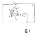
- FIG. 3shows the representation according to FIG. 1 at the start of the locking
- FIG. 4shows the representation according to FIG. 1 with locking of the building boards having progressed further
- FIG. 5shows the representation according to FIG. 1 with complete connection and locking of the two building boards
- FIG. 6shows two building boards at the joint in partial view with a release element
- FIG. 7shows a representation analogous to FIG. 1 with a second locking element
- FIG. 8shows a representation analogous to FIG. 2 with the second locking element
- FIG. 9shows a representation analogous to FIG. 4 with the second locking element
- FIG. 10shows a representation analogous to FIG. 5 with the second locking element
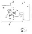
- FIG. 11shows a representation analogous to FIG. 1 with a further exemplary embodiment
- FIG. 12shows a representation analogous to FIG. 2 with the further exemplary embodiment
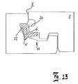
- FIG. 13shows a representation analogous to FIG. 3 with the further exemplary embodiment
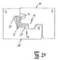
- FIG. 14shows a representation analogous to FIG. 4 with the further exemplary embodiment
- FIG. 15shows a representation analogous to FIG. 5 with the further exemplary embodiment
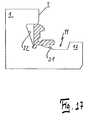
- FIG. 16shows the insertion of the locking element according to the first exemplary embodiment in a first step
- FIG. 17shows the insertion of the locking element according to the first exemplary embodiment in a second step
- FIG. 18shows the insertion of the locking element according to the first exemplary embodiment in a third step
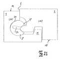
- FIG. 19shows two building boards at the joint in partial view with a third locking element at the start of joining
- FIG. 20shows a representation analogous to FIG. 2 with the third locking element
- FIG. 21shows a representation analogous to FIG. 2 with the third locking element
- FIG. 22shows a representation analogous to FIG. 4 with the third locking element
- FIG. 23shows a representation analogous to FIG. 5 with the third locking element
- FIG. 24shows a representation analogous to FIG. 2 with the fourth locking element
- FIG. 25shows a representation analogous to FIG. 4 with the fourth locking element
- FIG. 26shows a representation analogous to FIG. 5 with the fourth locking element.
- the inventionis to be explained for floor panels that can be connected to one another via the device according to the invention at their longitudinal sides as well as at their transverse sides or else at only one side.
- the deviceis provided to connect panels on their transverse sides.
- the longitudinal sidesare preferably connected by angling a new panel into a panel already lying on the floor and subsequent lowering onto the subfloor. The joining movement on the transverse side then takes place essentially in the vertical direction.
- the panels 1 , 2are provided on their lateral edges I, II with hook-shaped profiles 10 , 11 corresponding to one another. Even though a first and a second panel is spoken of here, each panel 1 , 2 is of course profiled identically and the profiles 10 , 11 correspond to one another.
- the panel 1is profiled starting from its top side 14 and the panel 2 is profiled starting from its underside 15 .
- the profiles 10 , 11are embodied in a step-shaped manner so that a groove 24 open at the top with an undercut 25 extending in the direction of the core 17 is embodied in the profile 11 of the first panel 1 .
- the profile 10 on the panel 2embodies a shoulder 8 projecting in the direction of the underside 15 and a groove 7 made transversely in the lateral edge II.
- the wall 22 of the undercut 25which wall faces towards the core 17 , runs tilted at an angle ⁇ of approx. 20° to the vertical. At its lower end the wall 22 merges into a relief groove 18 , which is embodied over the full length of the panel 1 .
- the essentially rigid locking element 3is embodied in an L-shaped manner in cross section and has the two legs 3 a , 3 b , which run essentially at right angles to one another.
- rigidmeans that the legs 3 a , 3 b are not embodied in a resilient manner with respect to one another.
- possible elastic deformations depending on the materiale.g., plastic
- the leg 3 ais provided with a projection 4 , the underside of which runs essentially parallel to the lower leg 3 b and forms a locking surface 13 .
- the legs 3 a , 3 bare undercut as shown in FIG. 6 .
- the locking element 3has a cylindrical projection 5 with which the locking element 3 is placed in the relief groove 18 of the groove 24 and thus held in a stationary manner.
- the locking element 3can be inserted in the panel 1 at the factory or placed into the groove 24 manually during laying. If the locking element 3 is inserted at the factory, it bears with its leg 3 a against the wall 22 tilted at an angle ⁇ and is attached there with an easily detachable pressure-sensitive adhesive so that it is ensured that it remains in this position during transport.
- FIG. 1shows, the underside of the lower lip 19 of the locking depression 7 formed by a groove rectangular in cross section comes into contact with the leg 3 b of the locking element 3 .
- FIGS. 2 to 5illustrate, through the joining movement, the locking element 3 is pivoted on a circular path about the cylindrical projection 5 until the projection 4 engages in the groove 7 and the locking surface 13 of the locking element 3 is in contact with the locking surface 20 of the groove 7 .
- the lower leg 3 bthen lies in a fitting manner in the groove 16 , which together with the profile 11 forms a closed chamber.
- the locking element 3is supported on the lower lip 26 and the wall 21 of the upper lip 27 or the undercut 25 .
- the top side of the projection 4is embodied in an arched manner as far as the locking surface 13 .
- the projection 8 of the second panel 2is supported in the depression 9 of the groove 24 of the first panel 1 .
- the locking in the horizontal directionis carried out by the walls 8 a running in the same angle of the projection 8 or 9 a of the depression 9 or of the projection 12 , which bear against one another.
- a clearance 28is embodied between the projection 12 projecting upward on the lower lip 26 and the depression 29 forming the projection 8 .
- FIGS. 7 through 10show a locking element 3 ′ that is embodied without a projection for stationary fixing in the groove 24 .
- the groove 7 ′ in the profile 10is not as pronounced as the groove 7 described above in the panel 2 .
- the locking projection 4is accommodated in the locking depression 7 ′ in a virtually positive manner.
- the manner of the horizontal and vertical lockingis identical.
- the locking mechanismoperates identically so that no further description is necessary here.
- the pull-out forcesthat is, the forces that must act on the panel 2 against the joining direction in order to release the connection
- the leg 3 bacts over its full length as a lever arm around the rotational point of the projection 5 (cf. FIG. 1 ).
- the locking element 3 , 3 ′ in the locked positionbears against the groove 24 at the bottom as well as against the wall 21 of the upper lip 27 .
- the forcesare applied via the lower lip 19 to the projection 4 .
- the rotational point of the locking element 3now does not lie below in the area of the cylindrical projection 5 , but above at the contact point of the projection 4 on the wall 21 of the upper lip 27 .
- the maximally effective lever armcorresponds to the horizontal spacing of the in FIG. 5 outermost right point of the locking surface 13 on the hook-shaped projection 4 and the lower end of the upper lip 27 and the lateral edge I of the panel 1 . This distance is much shorter than the length of the leg 3 b , so that for the same torque higher forces are necessary for releasing than for joining. It is also discernible from FIG.
- FIGS. 7 through 10show that during rotation of the locking element 3 ′ in a counter clockwise direction at the lower corner of the upper lip 27 a collision between the projection 4 and the edge already occurs that generates forces that counteract a rotation.
- it is therefore advisable to profile the upper lip 27in a rectangular manner at the lateral edge I and not to provide any chamfer in the lower area.
- FIG. 6shows how an unlocking of the panels 1 , 2 can take place when the connection is to be deliberately released.
- a rod element 33can be inserted laterally from outside into the groove 7 of the panel 2 , whereby the leg 3 a is spread and loses contact with the groove 7 , so that the panel 2 can be pivoted upwards.
- the elasticity of the leg 3 a with respect to the leg 3 bcan be adjusted via the size of the recess 6 .
- FIGS. 11 through 15show a special embodiment of the profile 11 of the first panel 1 .
- the wall 31 of the profile 11which wall adjoins the recess 18 , runs obliquely here. With full locking of the two panels 1 , 2 the lower leg 3 b of the locking element 3 thus does not bear against the lower lip 26 . It has been shown that with a profile 11 of this type the locking element 3 can be inserted into the relief groove 18 particularly easily.
- said locking element with its leg 3 bis first placed on the inclined wall 31 and then pushed into the relief groove 18 ( FIG. 16 ). Subsequently the locking element 3 is then pivoted in the direction of the inclined wall 22 in a counter clockwise manner and attached there by means of a pressure-sensitive adhesive.
- FIGS. 19 through 22show another exemplary embodiment of a locking element 3 ′′.
- the locking element 3 ′′is embodied in an essentially circular manner.
- a circle sectoris cut out.
- the profile 11 of the panel 1is embodied such that an essentially semicylindrical groove 30 is embodied, in which the locking element 3 ′′ is inserted.
- the locking projection 4 ′′is provided with a latch shoulder 4 a , which, as shown in FIG. 22 , bears against the lateral edge I of the panel 1 in the fully locked position, which prevents the locking element 3 ′′ from turning back.
- the locking element 3 ′′is embodied in an elastic manner. To increase the elasticity it preferably has a slot 34 starting from the circular sector, which slot projects radially out over the center of the locking element 3 ′. In cross section the locking recess 7 ′′ is embodied essentially in a triangular manner.
- FIGS. 23 through 26show another exemplary embodiment of a locking element 3 ′′′.
- the locking element 3 ′′is here embodied in an annular manner, wherein the annulus naturally is not closed. Its one end is formed by the locking projection 4 ′′′ and its other end the edge 32 analogous to the edge 32 of the locking element 3 ′′.
- Both locking elements 3 ′′ and 3 ′′′can be attached in the semicylindrical groove 30 by means of a pressure-sensitive adhesive in order to prevent an accidental twisting during transport.
- the locking element 3 ′′, 3 ′′′rotates during the further lowering movement in a clockwise manner and then latches with the locking projection 4 ′′, 4 ′′′ into the locking depression 7 ′′, 7 ′′′.
- the locking element 3 ′′′ annular in cross sectionis also provided on the locking projection 4 ′′′ with a latch shoulder 4 a , which due to the elasticity of the locking element 3 ′′′ snaps behind the joint edge 35 and in the fully locked position bears against the lateral edge I of panel 1 and prevents the locking element 3 ′′′ from turning back.
- All of the locking elements 3 , 3 ′, 3 ′′, 3 ′′′can comprise plastic, a wood material/plastic mixture or a metal.
- Plastichas the advantage that it can be processed in injection molding or extrusion methods.
- a wood material/plastic mixturecan be processed in an extrusion method and a locking element 3 , 3 ′, 3 ′′, 3 ′′′ of metal can be produced in a forming method, for example by rolling.
Landscapes
- Engineering & Computer Science (AREA)
- Architecture (AREA)
- General Engineering & Computer Science (AREA)
- Mechanical Engineering (AREA)
- Civil Engineering (AREA)
- Structural Engineering (AREA)
- Floor Finish (AREA)
- Joining Of Building Structures In Genera (AREA)
Abstract
Description
Claims (19)
Applications Claiming Priority (3)
| Application Number | Priority Date | Filing Date | Title |
|---|---|---|---|
| DE102007042250 | 2007-09-06 | ||
| DE102007042250ADE102007042250B4 (en) | 2007-09-06 | 2007-09-06 | Device for connecting and locking two building panels, in particular floor panels |
| DE102007042250.6 | 2007-09-06 |
Publications (2)
| Publication Number | Publication Date |
|---|---|
| US20090100782A1 US20090100782A1 (en) | 2009-04-23 |
| US7980039B2true US7980039B2 (en) | 2011-07-19 |
Family
ID=40043015
Family Applications (1)
| Application Number | Title | Priority Date | Filing Date |
|---|---|---|---|
| US12/202,864Expired - Fee RelatedUS7980039B2 (en) | 2007-09-06 | 2008-09-02 | Device for connecting and interlocking of two base plates, especially floor panels |
Country Status (6)
| Country | Link |
|---|---|
| US (1) | US7980039B2 (en) |
| EP (1) | EP2034106B1 (en) |
| AT (1) | ATE498748T1 (en) |
| DE (2) | DE102007042250B4 (en) |
| ES (1) | ES2359534T3 (en) |
| PL (1) | PL2034106T3 (en) |
Cited By (56)
| Publication number | Priority date | Publication date | Assignee | Title |
|---|---|---|---|---|
| US20100281803A1 (en)* | 2007-11-23 | 2010-11-11 | Mark Cappelle | Floor panel |
| US20110167750A1 (en)* | 2010-01-12 | 2011-07-14 | Valinge Innovation Ab | Mechanical locking system for floor panels |
| US20110173914A1 (en)* | 2010-01-15 | 2011-07-21 | Nils-Erik Engstrom | Set of panels comprising retaining profiles with a separate clip and method for inserting the clip |
| US20120317916A1 (en)* | 2010-03-02 | 2012-12-20 | Kwang Seok Oh | Flooring material and a rotational body used therewith |
| WO2013025164A1 (en)* | 2011-08-15 | 2013-02-21 | Välinge Flooring Technology AB | Mechanical locking system for floor panels |
| US20130152500A1 (en)* | 2011-12-15 | 2013-06-20 | Nils-Erik Engström | Set of panels with clip |
| US8544233B2 (en) | 2000-03-31 | 2013-10-01 | Pergo (Europe) Ab | Building panels |
| US8544234B2 (en) | 2007-11-07 | 2013-10-01 | Valinge Innovation Ab | Mechanical locking of floor panels with vertical snap folding |
| US8572922B2 (en) | 2011-07-05 | 2013-11-05 | Valinge Flooring Technology Ab | Mechanical locking of floor panels with a glued tongue |
| US8596013B2 (en) | 2012-04-04 | 2013-12-03 | Valinge Innovation Ab | Building panel with a mechanical locking system |
| US8627862B2 (en) | 2008-01-31 | 2014-01-14 | Valinge Innovation Ab | Mechanical locking of floor panels, methods to install and uninstall panels, a method and an equipment to produce the locking system, a method to connect a displaceable tongue to a panel and a tongue blank |
| US8635829B2 (en) | 2009-09-15 | 2014-01-28 | Guido Schulte | Covering consisting of elements that can be mechanically interconnected and method for producing elements |
| US8650826B2 (en) | 2011-07-19 | 2014-02-18 | Valinge Flooring Technology Ab | Mechanical locking system for floor panels |
| US8661762B2 (en) | 1995-03-07 | 2014-03-04 | Pergo (Europe) Ab | Flooring panel or wall panel and use thereof |
| US8713886B2 (en) | 2009-01-30 | 2014-05-06 | Valinge Innovation Ab | Mechanical lockings of floor panels and a tongue blank |
| US8752352B2 (en) | 2009-10-02 | 2014-06-17 | Guido Schulte | Covering from mechanically interconnectable elements |
| US8763340B2 (en) | 2011-08-15 | 2014-07-01 | Valinge Flooring Technology Ab | Mechanical locking system for floor panels |
| US8769905B2 (en) | 2011-08-15 | 2014-07-08 | Valinge Flooring Technology Ab | Mechanical locking system for floor panels |
| US8776473B2 (en) | 2010-02-04 | 2014-07-15 | Valinge Innovation Ab | Mechanical locking system for floor panels |
| US8806832B2 (en) | 2011-03-18 | 2014-08-19 | Inotec Global Limited | Vertical joint system and associated surface covering system |
| US20140286701A1 (en)* | 2011-05-25 | 2014-09-25 | Steen Sauer | Assembling of drawer |
| US8857126B2 (en) | 2011-08-15 | 2014-10-14 | Valinge Flooring Technology Ab | Mechanical locking system for floor panels |
| US8869485B2 (en) | 2006-12-08 | 2014-10-28 | Valinge Innovation Ab | Mechanical locking of floor panels |
| US8887468B2 (en) | 2011-05-06 | 2014-11-18 | Valinge Flooring Technology Ab | Mechanical locking system for building panels |
| US20140348580A1 (en)* | 2006-12-17 | 2014-11-27 | Unilin, Bvba | Composed element, multi-layered board and panel-shaped element for forming this composed element |
| US8925274B2 (en) | 2008-05-15 | 2015-01-06 | Valinge Innovation Ab | Mechanical locking of building panels |
| US8978334B2 (en) | 2010-05-10 | 2015-03-17 | Pergo (Europe) Ab | Set of panels |
| US8997430B1 (en) | 2010-04-15 | 2015-04-07 | Spanolux N.V.-Div. Balterio | Floor panel assembly |
| US9032685B2 (en) | 1995-03-07 | 2015-05-19 | Pergo (Europe) Ab | Flooring panel or wall panel and use thereof |
| US20150252573A1 (en)* | 2014-03-06 | 2015-09-10 | Flooring Industries Limited, Sarl | Flooring industries limited SARL |
| US9206611B2 (en)* | 2010-01-14 | 2015-12-08 | Spanolux N.V.—Div. Balterio | Floor panel assembly and floor panel for use therein |
| US9216541B2 (en) | 2012-04-04 | 2015-12-22 | Valinge Innovation Ab | Method for producing a mechanical locking system for building panels |
| US9290948B2 (en) | 2009-01-16 | 2016-03-22 | Flooring Industries Limited, Sarl | Floor panel |
| US9290950B2 (en) | 2012-01-05 | 2016-03-22 | Flooring Industries Limited, Sarl | Panel |
| US9322162B2 (en) | 1998-02-04 | 2016-04-26 | Pergo (Europe) Ab | Guiding means at a joint |
| US9366036B2 (en) | 2012-11-22 | 2016-06-14 | Ceraloc Innovation Ab | Mechanical locking system for floor panels |
| US9382716B2 (en) | 2006-07-11 | 2016-07-05 | Valinge Innovation Ab | Mechanical locking of floor panels with a flexible bristle tongue |
| US9458634B2 (en) | 2014-05-14 | 2016-10-04 | Valinge Innovation Ab | Building panel with a mechanical locking system |
| US9464443B2 (en) | 1998-10-06 | 2016-10-11 | Pergo (Europe) Ab | Flooring material comprising flooring elements which are assembled by means of separate flooring elements |
| US9719542B2 (en) | 2010-06-03 | 2017-08-01 | Unilin, Bvba | Composed element and corner connection applied herewith |
| US9725912B2 (en) | 2011-07-11 | 2017-08-08 | Ceraloc Innovation Ab | Mechanical locking system for floor panels |
| US9945130B2 (en) | 2013-03-08 | 2018-04-17 | Valinge Innovation Ab | Building panels provided with a mechanical locking system |
| US10017948B2 (en) | 2013-06-27 | 2018-07-10 | Valinge Innovation Ab | Building panel with a mechanical locking system |
| US10041258B2 (en) | 2013-10-25 | 2018-08-07 | Ceraloc Innovation Ab | Mechanical locking system for floor panels |
| US10060139B2 (en) | 2013-07-09 | 2018-08-28 | Ceraloc Innovation Ab | Mechanical locking system for floor panels |
| US10138636B2 (en) | 2014-11-27 | 2018-11-27 | Valinge Innovation Ab | Mechanical locking system for floor panels |
| US10246883B2 (en) | 2014-05-14 | 2019-04-02 | Valinge Innovation Ab | Building panel with a mechanical locking system |
| US10293512B2 (en) | 2011-06-29 | 2019-05-21 | Unilin Bvba | Drawer, drawer construction and method for manufacturing a drawer |
| US10815676B2 (en) | 2010-05-10 | 2020-10-27 | Flooring Industries Limited, Sarl | Floor panel |
| US11060302B2 (en) | 2019-01-10 | 2021-07-13 | Valinge Innovation Ab | Unlocking system for panels |
| US11208812B2 (en) | 2018-06-13 | 2021-12-28 | Ceraloc Innovation Ab | Flooring system provided with a connecting system and an associated connecting device |
| US11459774B2 (en)* | 2017-07-18 | 2022-10-04 | Xylo Technologies Ag | Panels with a detachable protruding lip for wall- , ceiling- or floor coverings |
| US20230287673A1 (en)* | 2022-03-08 | 2023-09-14 | Fergus Jonathan Ardern | Releasable connection means |
| US11987990B2 (en) | 2007-11-07 | 2024-05-21 | Välinge Innovation AB | Mechanical locking of floor panels with vertical snap folding |
| US20240218671A1 (en)* | 2017-03-21 | 2024-07-04 | Unilin, Bv | Floor panel for forming a floor covering |
| US12123204B2 (en) | 2019-11-07 | 2024-10-22 | Lignum Technologies Ag | Panels with a detachable protruding lip for wall-, ceiling- or floor coverings |
Families Citing this family (32)
| Publication number | Priority date | Publication date | Assignee | Title |
|---|---|---|---|---|
| US11725394B2 (en) | 2006-11-15 | 2023-08-15 | Välinge Innovation AB | Mechanical locking of floor panels with vertical folding |
| US8689512B2 (en) | 2006-11-15 | 2014-04-08 | Valinge Innovation Ab | Mechanical locking of floor panels with vertical folding |
| US7726088B2 (en)* | 2007-07-20 | 2010-06-01 | Moritz Andre Muehlebach | Flooring system |
| US8220217B2 (en)* | 2007-07-20 | 2012-07-17 | Innovaris Ag | Flooring system |
| US8505257B2 (en)* | 2008-01-31 | 2013-08-13 | Valinge Innovation Ab | Mechanical locking of floor panels |
| BE1018480A3 (en)* | 2008-04-16 | 2011-01-11 | Flooring Ind Ltd Sarl | FLOOR PANELS, FLOOR CLADDING MADE UP OF THEM, AND METHOD FOR MANUFACTURING SUCH FLOOR PANELS. |
| EP2236694A1 (en)* | 2009-03-25 | 2010-10-06 | Spanolux N.V.- DIV. Balterio | A fastening system and a panel |
| DE102009022483A1 (en)* | 2009-05-25 | 2010-12-02 | Pergo (Europe) Ab | Set of panels, in particular floor panels |
| DE102009034902B4 (en)* | 2009-07-27 | 2015-10-01 | Guido Schulte | Surface made of mechanically interconnectable panels |
| US8234830B2 (en)* | 2010-02-04 | 2012-08-07 | Välinge Innovations AB | Mechanical locking system for floor panels |
| US8591696B2 (en) | 2010-11-17 | 2013-11-26 | Pergo (Europe) Ab | Method for manufacturing a surface element |
| HUE030211T2 (en)* | 2011-07-19 | 2017-04-28 | Ceraloc Innovation Ab | Mechanical locking system for building elements |
| DE102012102339A1 (en)* | 2011-07-29 | 2013-01-31 | Hamberger Industriewerke Gmbh | Connection for elastic or plate-shaped components, profile slides and floor coverings |
| CN103748298B (en)* | 2011-08-15 | 2016-08-17 | 塞拉洛克创新股份有限公司 | Mechanical locking system for floor panels |
| DE102011119889A1 (en)* | 2011-11-28 | 2013-05-29 | Falquon Gmbh | System for connecting and locking of panels such as floor panel, has projection arranged on long arm of locking element, which is faced in direction opposing to short arm, and is anchored in groove |
| DE102011122086A1 (en) | 2011-12-22 | 2013-06-27 | Falquon Gmbh | System for connecting and locking structural panels i.e. floor panels, has side edge comprising groove to accommodate short bracket, another groove formed at another edge and extension formed at long bracket and anchored into latter groove |
| EP2674546A1 (en)* | 2012-06-11 | 2013-12-18 | Falquon GmbH | System for connecting and locking two building slabs |
| BE1021833B1 (en)* | 2013-05-30 | 2016-01-21 | Flooring Industries Limited Sarl | PANEL |
| DE102013108538A1 (en)* | 2013-08-07 | 2015-02-12 | Hamberger Industriewerke Gmbh | Connection and locking element |
| DE102013112550A1 (en)* | 2013-08-07 | 2015-02-12 | Hamberger Industriewerke Gmbh | Connection for plate-shaped components |
| WO2015070890A1 (en)* | 2013-11-12 | 2015-05-21 | Grigorij Wagner | Flooring component |
| DE102013113874B4 (en)* | 2013-12-11 | 2024-08-14 | Guido Schulte | Wall, floor or ceiling panel system with removable plank |
| EP3122958B1 (en) | 2014-03-24 | 2022-01-26 | Flooring Industries Limited, SARL | A set of mutually lockable panels |
| US9260870B2 (en) | 2014-03-24 | 2016-02-16 | Ivc N.V. | Set of mutually lockable panels |
| CN105442831B (en)* | 2014-09-25 | 2018-05-04 | 能诚集团有限公司 | A kind of oblique angle tongue and groove building template |
| BE1024157B1 (en)* | 2016-04-25 | 2017-11-24 | Flooring Industries Limited, Sarl | Set of floor panels and method for installing this set of floor panels. |
| IT201800003829A1 (en)* | 2018-03-21 | 2019-09-21 | Modulnova S R L | FURNITURE ELEMENT AND METHOD OF MAKING THIS FURNISHING ELEMENT |
| CN108825932B (en)* | 2018-05-28 | 2020-04-03 | 江苏亚太波纹管有限公司 | Heat supply network heat supply pipeline combined installation type heat preservation cotton pipe |
| BE1027032B1 (en)* | 2019-02-07 | 2020-09-07 | Flooring Ind Ltd Sarl | Panel and trim formed with such panels |
| DE202019101580U1 (en)* | 2019-03-20 | 2020-06-30 | Otto Fuchs - Kommanditgesellschaft - | Profile network |
| US12071769B2 (en)* | 2021-02-03 | 2024-08-27 | Valinge Innovation Ab | Building panels comprising a locking device |
| CN115727045B (en)* | 2022-12-16 | 2023-07-25 | 广东卡诺亚家居股份有限公司 | Panel binding off component, panel binding off structure |
Citations (9)
| Publication number | Priority date | Publication date | Assignee | Title |
|---|---|---|---|---|
| US4417430A (en)* | 1981-03-13 | 1983-11-29 | Standard Keil Hardware Manufacturing Co. | Direct drive positive locking panel fastener |
| US5424118A (en)* | 1994-01-25 | 1995-06-13 | Mid-South Industries, Inc. | Interlocking insulative panel construction |
| WO2003016654A1 (en)* | 2001-08-10 | 2003-02-27 | Akzenta Paneele + Profile Gmbh | Panel and fastening system for such a panel |
| WO2006043893A1 (en) | 2004-10-22 | 2006-04-27 | Välinge Innovation AB | Mechanical locking of floor panels with a flexible tongue |
| US20070006543A1 (en) | 2005-07-11 | 2007-01-11 | Pergo (Europe) Ab | Joint for panels |
| US20070028547A1 (en)* | 2003-03-24 | 2007-02-08 | Kronotec Ag | Device for connecting building boards, especially floor panels |
| WO2008004960A2 (en) | 2006-12-08 | 2008-01-10 | Välinge Innovation AB | Mechanical locking of floor panels |
| US20090019806A1 (en)* | 2007-07-20 | 2009-01-22 | Moritz Andre Muehlebach | Flooring system |
| US7621092B2 (en)* | 2006-02-10 | 2009-11-24 | Flooring Technologies Ltd. | Device and method for locking two building boards |
- 2007
- 2007-09-06DEDE102007042250Apatent/DE102007042250B4/ennot_activeExpired - Fee Related
- 2008
- 2008-09-02USUS12/202,864patent/US7980039B2/ennot_activeExpired - Fee Related
- 2008-09-03DEDE502008002598Tpatent/DE502008002598D1/enactiveActive
- 2008-09-03ATAT08015526Tpatent/ATE498748T1/enactive
- 2008-09-03EPEP08015526Apatent/EP2034106B1/ennot_activeNot-in-force
- 2008-09-03PLPL08015526Tpatent/PL2034106T3/enunknown
- 2008-09-03ESES08015526Tpatent/ES2359534T3/enactiveActive
Patent Citations (12)
| Publication number | Priority date | Publication date | Assignee | Title |
|---|---|---|---|---|
| US4417430A (en)* | 1981-03-13 | 1983-11-29 | Standard Keil Hardware Manufacturing Co. | Direct drive positive locking panel fastener |
| US5424118A (en)* | 1994-01-25 | 1995-06-13 | Mid-South Industries, Inc. | Interlocking insulative panel construction |
| WO2003016654A1 (en)* | 2001-08-10 | 2003-02-27 | Akzenta Paneele + Profile Gmbh | Panel and fastening system for such a panel |
| EP1415056A1 (en) | 2001-08-10 | 2004-05-06 | Akzenta Paneele + Profile GmbH | Panel and fastening system for such a panel |
| US20040211143A1 (en)* | 2001-08-10 | 2004-10-28 | Hans-Jurgen Hanning | Panel and fastening system for such a panel |
| US20070028547A1 (en)* | 2003-03-24 | 2007-02-08 | Kronotec Ag | Device for connecting building boards, especially floor panels |
| WO2006043893A1 (en) | 2004-10-22 | 2006-04-27 | Välinge Innovation AB | Mechanical locking of floor panels with a flexible tongue |
| US20080134607A1 (en)* | 2004-10-22 | 2008-06-12 | Valinge Innovation Ab | Mechanical Locking of Floor Panels With a Flexible Tongue |
| US20070006543A1 (en) | 2005-07-11 | 2007-01-11 | Pergo (Europe) Ab | Joint for panels |
| US7621092B2 (en)* | 2006-02-10 | 2009-11-24 | Flooring Technologies Ltd. | Device and method for locking two building boards |
| WO2008004960A2 (en) | 2006-12-08 | 2008-01-10 | Välinge Innovation AB | Mechanical locking of floor panels |
| US20090019806A1 (en)* | 2007-07-20 | 2009-01-22 | Moritz Andre Muehlebach | Flooring system |
Cited By (170)
| Publication number | Priority date | Publication date | Assignee | Title |
|---|---|---|---|---|
| US8875465B2 (en) | 1995-03-07 | 2014-11-04 | Pergo (Europe) Ab | Flooring panel or wall panel and use thereof |
| US8661762B2 (en) | 1995-03-07 | 2014-03-04 | Pergo (Europe) Ab | Flooring panel or wall panel and use thereof |
| US9032685B2 (en) | 1995-03-07 | 2015-05-19 | Pergo (Europe) Ab | Flooring panel or wall panel and use thereof |
| US9322162B2 (en) | 1998-02-04 | 2016-04-26 | Pergo (Europe) Ab | Guiding means at a joint |
| US9464443B2 (en) | 1998-10-06 | 2016-10-11 | Pergo (Europe) Ab | Flooring material comprising flooring elements which are assembled by means of separate flooring elements |
| US9534397B2 (en) | 2000-03-31 | 2017-01-03 | Pergo (Europe) Ab | Flooring material |
| US8544233B2 (en) | 2000-03-31 | 2013-10-01 | Pergo (Europe) Ab | Building panels |
| US9316006B2 (en) | 2000-03-31 | 2016-04-19 | Pergo (Europe) Ab | Building panels |
| US10626619B2 (en) | 2000-03-31 | 2020-04-21 | Unilin Nordic Ab | Flooring material |
| US10233653B2 (en) | 2000-03-31 | 2019-03-19 | Pergo (Europe) Ab | Flooring material |
| US8578675B2 (en) | 2000-03-31 | 2013-11-12 | Pergo (Europe) Ab | Process for sealing of a joint |
| US9255414B2 (en) | 2000-03-31 | 2016-02-09 | Pergo (Europe) Ab | Building panels |
| US9677285B2 (en) | 2000-03-31 | 2017-06-13 | Pergo (Europe) Ab | Building panels |
| US9260869B2 (en) | 2000-03-31 | 2016-02-16 | Pergo (Europe) Ab | Building panels |
| US9611656B2 (en) | 2000-03-31 | 2017-04-04 | Pergo (Europe) Ab | Building panels |
| US10156078B2 (en) | 2000-03-31 | 2018-12-18 | Pergo (Europe) Ab | Building panels |
| US11680415B2 (en) | 2006-07-11 | 2023-06-20 | Valinge Innovation Ab | Mechanical locking of floor panels with a flexible bristle tongue |
| US11193283B2 (en) | 2006-07-11 | 2021-12-07 | Valinge Innovation Ab | Mechanical locking of floor panels with a flexible bristle tongue |
| US10669723B2 (en) | 2006-07-11 | 2020-06-02 | Valinge Innovation Ab | Mechanical locking of floor panels with a flexible bristle tongue |
| US9382716B2 (en) | 2006-07-11 | 2016-07-05 | Valinge Innovation Ab | Mechanical locking of floor panels with a flexible bristle tongue |
| US8869485B2 (en) | 2006-12-08 | 2014-10-28 | Valinge Innovation Ab | Mechanical locking of floor panels |
| US20140348580A1 (en)* | 2006-12-17 | 2014-11-27 | Unilin, Bvba | Composed element, multi-layered board and panel-shaped element for forming this composed element |
| US11987990B2 (en) | 2007-11-07 | 2024-05-21 | Välinge Innovation AB | Mechanical locking of floor panels with vertical snap folding |
| US8544234B2 (en) | 2007-11-07 | 2013-10-01 | Valinge Innovation Ab | Mechanical locking of floor panels with vertical snap folding |
| US10995500B2 (en) | 2007-11-23 | 2021-05-04 | Flooring Industries Limited, Sarl | Floor panel |
| US8966852B2 (en) | 2007-11-23 | 2015-03-03 | Flooring Industries Limited, Sarl | Floor panel |
| US10815674B2 (en) | 2007-11-23 | 2020-10-27 | Flooring Industries Limited, Sarl | Floor panel |
| US9371654B2 (en) | 2007-11-23 | 2016-06-21 | Flooring Industries Limited, Sarl | Floor panel |
| US8621814B2 (en)* | 2007-11-23 | 2014-01-07 | Flooring Industries Limited, Sarl | Floor panel |
| US11668101B2 (en) | 2007-11-23 | 2023-06-06 | Flooring Industries Limited, Sarl | Floor panel |
| US20100281803A1 (en)* | 2007-11-23 | 2010-11-11 | Mark Cappelle | Floor panel |
| US9340974B2 (en) | 2008-01-31 | 2016-05-17 | Valinge Innovation Ab | Mechanical locking of floor panels |
| US10006210B2 (en) | 2008-01-31 | 2018-06-26 | Valinge Innovation Ab | Mechanical locking of floor panels |
| US12024898B2 (en) | 2008-01-31 | 2024-07-02 | Välinge Innovation AB | Mechanical locking of floor panels |
| US11078673B2 (en) | 2008-01-31 | 2021-08-03 | Valinge Innovation Ab | Mechanical locking of floor panels |
| US8627862B2 (en) | 2008-01-31 | 2014-01-14 | Valinge Innovation Ab | Mechanical locking of floor panels, methods to install and uninstall panels, a method and an equipment to produce the locking system, a method to connect a displaceable tongue to a panel and a tongue blank |
| US10526792B2 (en) | 2008-01-31 | 2020-01-07 | Valinge Innovation Ab | Mechanical locking of floor panels |
| US8925274B2 (en) | 2008-05-15 | 2015-01-06 | Valinge Innovation Ab | Mechanical locking of building panels |
| US10935063B2 (en) | 2008-12-17 | 2021-03-02 | Unilin Bv | Composed element, multi-layered board and panel-shaped element for forming this composed element |
| US12123441B2 (en) | 2008-12-17 | 2024-10-22 | Unilin Bv | Composed element, multi-layered board and panel-shaped element for forming this composed element |
| US9695856B2 (en) | 2008-12-17 | 2017-07-04 | Unilin, Bvba | Composed element, multi-layered board and panel-shaped element for forming this composed element |
| US10731689B2 (en) | 2008-12-17 | 2020-08-04 | Unilin, Bvba | Composed element, multi-layered board and panel-shaped element for forming this composed element |
| US11085475B2 (en) | 2008-12-17 | 2021-08-10 | Flooring Industries Limited, Sarl | Composed element, multi-layered board and panel-shaped element for forming this composed element |
| US9797427B2 (en) | 2008-12-17 | 2017-10-24 | Unilin, Bvba | Composed element, multi-layered board and panel-shaped element for forming this composed element |
| US11319977B2 (en) | 2008-12-17 | 2022-05-03 | Flooring Industries Limited, Sarl | Composed element, multi-layered board and panel-shaped element for forming this composed element |
| US9347470B2 (en)* | 2008-12-17 | 2016-05-24 | Unilin, Bvba | Composed element, multi-layered board and panel-shaped element for forming this composed element |
| US11788568B2 (en) | 2008-12-17 | 2023-10-17 | Flooring Industries Limited Sarl | Composed element, multi-layered board and panel-shaped element for forming this composed element |
| US10323670B2 (en) | 2008-12-17 | 2019-06-18 | Unilin, Bvba | Composed element, multi-layered board and panel-shaped element for forming this composed element |
| US9175703B2 (en) | 2008-12-17 | 2015-11-03 | Unilin, Bvba | Composed element, multi-layered board and panel-shaped element for forming this composed element |
| US9290948B2 (en) | 2009-01-16 | 2016-03-22 | Flooring Industries Limited, Sarl | Floor panel |
| US10934721B2 (en)* | 2009-01-30 | 2021-03-02 | Valinge Innovation Ab | Mechanical lockings of floor panels and a tongue blank |
| US8713886B2 (en) | 2009-01-30 | 2014-05-06 | Valinge Innovation Ab | Mechanical lockings of floor panels and a tongue blank |
| US10214915B2 (en)* | 2009-01-30 | 2019-02-26 | Valinge Innovation Ab | Mechanical lockings of floor panels and a tongue blank |
| US20190376298A1 (en)* | 2009-01-30 | 2019-12-12 | Valinge Innovation Ab | Mechanical lockings of floor panels and a tongue blank |
| US9540826B2 (en)* | 2009-01-30 | 2017-01-10 | Valinge Innovation Ab | Mechanical lockings of floor panels and a tongue blank |
| US8635829B2 (en) | 2009-09-15 | 2014-01-28 | Guido Schulte | Covering consisting of elements that can be mechanically interconnected and method for producing elements |
| US8752352B2 (en) | 2009-10-02 | 2014-06-17 | Guido Schulte | Covering from mechanically interconnectable elements |
| US8898988B2 (en) | 2010-01-12 | 2014-12-02 | Valinge Innovation Ab | Mechanical locking system for floor panels |
| US20110167750A1 (en)* | 2010-01-12 | 2011-07-14 | Valinge Innovation Ab | Mechanical locking system for floor panels |
| US8544230B2 (en) | 2010-01-12 | 2013-10-01 | Valinge Innovation Ab | Mechanical locking system for floor panels |
| US9453347B2 (en) | 2010-01-12 | 2016-09-27 | Valinge Innovation Ab | Mechanical locking system for floor panels |
| US9206611B2 (en)* | 2010-01-14 | 2015-12-08 | Spanolux N.V.—Div. Balterio | Floor panel assembly and floor panel for use therein |
| US8631623B2 (en) | 2010-01-15 | 2014-01-21 | Pergo (Europe) Ab | Set of panels comprising retaining profiles with a separate clip and method for inserting the clip |
| US20140157721A1 (en)* | 2010-01-15 | 2014-06-12 | Pergo (Europe) Ab | Set of panels comprising retaining profiles with a separate clip and method for inserting the clip |
| US9464444B2 (en) | 2010-01-15 | 2016-10-11 | Pergo (Europe) Ab | Set of panels comprising retaining profiles with a separate clip and method for inserting the clip |
| US20110173914A1 (en)* | 2010-01-15 | 2011-07-21 | Nils-Erik Engstrom | Set of panels comprising retaining profiles with a separate clip and method for inserting the clip |
| US9115500B2 (en)* | 2010-01-15 | 2015-08-25 | Pergo (Europe) Ab | Set of panels comprising retaining profiles with a separate clip and method for inserting the clip |
| US8615952B2 (en)* | 2010-01-15 | 2013-12-31 | Pergo (Europe) Ab | Set of panels comprising retaining profiles with a separate clip and method for inserting the clip |
| US8776473B2 (en) | 2010-02-04 | 2014-07-15 | Valinge Innovation Ab | Mechanical locking system for floor panels |
| US9428919B2 (en) | 2010-02-04 | 2016-08-30 | Valinge Innovation Ab | Mechanical locking system for floor panels |
| US8590250B2 (en)* | 2010-03-02 | 2013-11-26 | Kwang Seok Oh | Flooring material and a rotational body used therewith |
| US20120317916A1 (en)* | 2010-03-02 | 2012-12-20 | Kwang Seok Oh | Flooring material and a rotational body used therewith |
| US9003735B2 (en) | 2010-04-15 | 2015-04-14 | Spanolux N.V.—Div. Balterio | Floor panel assembly |
| US8997430B1 (en) | 2010-04-15 | 2015-04-07 | Spanolux N.V.-Div. Balterio | Floor panel assembly |
| US9476208B2 (en) | 2010-04-15 | 2016-10-25 | Spanolux N.V.—Div. Balterio | Floor panel assembly |
| US12123201B2 (en) | 2010-05-10 | 2024-10-22 | Unilin, Bv | Floor panel |
| US10815676B2 (en) | 2010-05-10 | 2020-10-27 | Flooring Industries Limited, Sarl | Floor panel |
| US11976471B2 (en) | 2010-05-10 | 2024-05-07 | Unilin Bv | Floor panel |
| US11236514B2 (en) | 2010-05-10 | 2022-02-01 | Flooring Industries Limited, Sarl | Floor panel |
| US10927553B2 (en) | 2010-05-10 | 2021-02-23 | Flooring Industries Limited, Sarl | Floor panel |
| US11505949B2 (en) | 2010-05-10 | 2022-11-22 | Flooring Industries Limited, Sarl | Floor panel |
| US10889998B2 (en) | 2010-05-10 | 2021-01-12 | Flooring Industries Limited, Sarl | Floor panel |
| US10876303B2 (en) | 2010-05-10 | 2020-12-29 | Flooring Industries Limited, Sarl | Floor panel |
| US12012764B2 (en) | 2010-05-10 | 2024-06-18 | Unilin Bv | Floor panel |
| US11377857B2 (en) | 2010-05-10 | 2022-07-05 | Flooring Industries Limited, Sarl | Floor panel |
| US9593491B2 (en) | 2010-05-10 | 2017-03-14 | Pergo (Europe) Ab | Set of panels |
| US12031337B2 (en) | 2010-05-10 | 2024-07-09 | Unilin, Bv | Floor panel |
| US11193282B2 (en) | 2010-05-10 | 2021-12-07 | Flooring Industries Limited, Sarl | Floor panel |
| US8978334B2 (en) | 2010-05-10 | 2015-03-17 | Pergo (Europe) Ab | Set of panels |
| US12000418B2 (en) | 2010-06-03 | 2024-06-04 | Unilin, Bv | Composed element and corner connection applied herewith |
| US9719542B2 (en) | 2010-06-03 | 2017-08-01 | Unilin, Bvba | Composed element and corner connection applied herewith |
| US10982700B2 (en) | 2010-06-03 | 2021-04-20 | Unilin Bv | Composed element and corner connection applied herewith |
| US12139918B2 (en) | 2011-03-18 | 2024-11-12 | Välinge Innovation AB | Vertical joint system and associated surface covering system |
| US10000935B2 (en) | 2011-03-18 | 2018-06-19 | Inotec Global Limited | Vertical joint system and associated surface covering system |
| US8806832B2 (en) | 2011-03-18 | 2014-08-19 | Inotec Global Limited | Vertical joint system and associated surface covering system |
| US9103126B2 (en) | 2011-03-18 | 2015-08-11 | Inotec Global Limited | Vertical joint system and associated surface covering system |
| US11781577B2 (en) | 2011-05-06 | 2023-10-10 | Valinge Innovation Ab | Mechanical locking system for building panels |
| US8887468B2 (en) | 2011-05-06 | 2014-11-18 | Valinge Flooring Technology Ab | Mechanical locking system for building panels |
| US12276293B2 (en) | 2011-05-06 | 2025-04-15 | Välinge Innovation AB | Mechanical locking system for building panels |
| US20140286701A1 (en)* | 2011-05-25 | 2014-09-25 | Steen Sauer | Assembling of drawer |
| US9599139B2 (en)* | 2011-05-25 | 2017-03-21 | Steen Sauer | Assembling of drawer |
| US10293512B2 (en) | 2011-06-29 | 2019-05-21 | Unilin Bvba | Drawer, drawer construction and method for manufacturing a drawer |
| US9856656B2 (en) | 2011-07-05 | 2018-01-02 | Ceraloc Innovation Ab | Mechanical locking of floor panels with a glued tongue |
| US8959866B2 (en) | 2011-07-05 | 2015-02-24 | Valinge Flooring Technology Ab | Mechanical locking of floor panels with a glued tongue |
| US8572922B2 (en) | 2011-07-05 | 2013-11-05 | Valinge Flooring Technology Ab | Mechanical locking of floor panels with a glued tongue |
| US9725912B2 (en) | 2011-07-11 | 2017-08-08 | Ceraloc Innovation Ab | Mechanical locking system for floor panels |
| US10995501B2 (en) | 2011-07-11 | 2021-05-04 | Ceraloc Innovation Ab | Mechanical locking system for floor panels |
| US10519676B2 (en) | 2011-07-11 | 2019-12-31 | Ceraloc Innovation Ab | Mechanical locking system for floor panels |
| US9874027B2 (en) | 2011-07-19 | 2018-01-23 | Ceraloc Innovation Ab | Mechanical locking system for floor panels |
| US9284737B2 (en) | 2011-07-19 | 2016-03-15 | Valinge Flooring Technology Ab | Mechanical locking system for floor panels |
| US10240349B2 (en) | 2011-07-19 | 2019-03-26 | Ceraloc Innovation Ab | Mechanical locking system for floor panels |
| US8650826B2 (en) | 2011-07-19 | 2014-02-18 | Valinge Flooring Technology Ab | Mechanical locking system for floor panels |
| US10180005B2 (en) | 2011-08-15 | 2019-01-15 | Ceraloc Innovation Ab | Mechanical locking system for floor panels |
| US9051738B2 (en) | 2011-08-15 | 2015-06-09 | Valinge Flooring Technology Ab | Mechanical locking system for floor panels |
| US10968639B2 (en) | 2011-08-15 | 2021-04-06 | Ceraloc Innovation Ab | Mechanical locking system for floor panels |
| WO2013025164A1 (en)* | 2011-08-15 | 2013-02-21 | Välinge Flooring Technology AB | Mechanical locking system for floor panels |
| US10697187B2 (en) | 2011-08-15 | 2020-06-30 | Ceraloc Innovation Ab | Mechanical locking system for floor panels |
| US8857126B2 (en) | 2011-08-15 | 2014-10-14 | Valinge Flooring Technology Ab | Mechanical locking system for floor panels |
| US9657483B2 (en)* | 2011-08-15 | 2017-05-23 | Ceraloc Innovation Ab | Mechanical locking system for floor panels |
| US8769905B2 (en) | 2011-08-15 | 2014-07-08 | Valinge Flooring Technology Ab | Mechanical locking system for floor panels |
| US10221576B2 (en)* | 2011-08-15 | 2019-03-05 | Ceraloc Innovation Ab | Mechanical locking system for floor panels |
| US8763340B2 (en) | 2011-08-15 | 2014-07-01 | Valinge Flooring Technology Ab | Mechanical locking system for floor panels |
| US9388584B2 (en) | 2011-08-15 | 2016-07-12 | Ceraloc Innovation Ab | Mechanical locking system for floor panels |
| US20130152500A1 (en)* | 2011-12-15 | 2013-06-20 | Nils-Erik Engström | Set of panels with clip |
| US20150075104A1 (en)* | 2011-12-15 | 2015-03-19 | Pergo (Europe) Ab | Set of panels with clip |
| US9518394B2 (en)* | 2011-12-15 | 2016-12-13 | Pergo (Europe) Ab | Set of panels with clip |
| US8938929B2 (en)* | 2011-12-15 | 2015-01-27 | Pergo (Europe) Ab | Set of panels with clip |
| US9290950B2 (en) | 2012-01-05 | 2016-03-22 | Flooring Industries Limited, Sarl | Panel |
| US9476207B2 (en) | 2012-01-05 | 2016-10-25 | Flooring Industries Limited, Sarl | Panel |
| US10125488B2 (en)* | 2012-04-04 | 2018-11-13 | Valinge Innovation Ab | Building panel with a mechanical locking system |
| US9216541B2 (en) | 2012-04-04 | 2015-12-22 | Valinge Innovation Ab | Method for producing a mechanical locking system for building panels |
| US9663940B2 (en) | 2012-04-04 | 2017-05-30 | Valinge Innovation Ab | Building panel with a mechanical locking system |
| US9951526B2 (en) | 2012-04-04 | 2018-04-24 | Valinge Innovation Ab | Mechanical locking system for building panels |
| US9091077B2 (en)* | 2012-04-04 | 2015-07-28 | Valinge Innovation Ab | Building panel with a mechanical locking system |
| US9316002B2 (en)* | 2012-04-04 | 2016-04-19 | Valinge Innovation Ab | Building panel with a mechanical locking system |
| US10480196B2 (en) | 2012-04-04 | 2019-11-19 | Valinge Innovation Ab | Building panel with a mechanical locking system |
| US8596013B2 (en) | 2012-04-04 | 2013-12-03 | Valinge Innovation Ab | Building panel with a mechanical locking system |
| US10794065B2 (en) | 2012-04-04 | 2020-10-06 | Valinge Innovation Ab | Method for producing a mechanical locking system for building panels |
| US9771723B2 (en) | 2012-11-22 | 2017-09-26 | Ceraloc Innovation Ab | Mechanical locking system for floor panels |
| US9366036B2 (en) | 2012-11-22 | 2016-06-14 | Ceraloc Innovation Ab | Mechanical locking system for floor panels |
| US9945130B2 (en) | 2013-03-08 | 2018-04-17 | Valinge Innovation Ab | Building panels provided with a mechanical locking system |
| US10352049B2 (en) | 2013-06-27 | 2019-07-16 | Valinge Innovation Ab | Building panel with a mechanical locking system |
| US11066835B2 (en) | 2013-06-27 | 2021-07-20 | Valinge Innovation Ab | Building panel with a mechanical locking system |
| US12312816B2 (en) | 2013-06-27 | 2025-05-27 | Välinge Innovation AB | Building panel with a mechanical locking system |
| US10017948B2 (en) | 2013-06-27 | 2018-07-10 | Valinge Innovation Ab | Building panel with a mechanical locking system |
| US11746536B2 (en) | 2013-06-27 | 2023-09-05 | Valinge Innovation Ab | Building panel with a mechanical locking system |
| US10633870B2 (en) | 2013-07-09 | 2020-04-28 | Ceraloc Innovation Ab | Mechanical locking system for floor panels |
| US11434646B2 (en) | 2013-07-09 | 2022-09-06 | Ceraloc Innovation Ab | Mechanical locking system for floor panels |
| US11428014B2 (en) | 2013-07-09 | 2022-08-30 | Ceraloc Innovation Ab | Mechanical locking system for floor panels |
| US12077968B2 (en) | 2013-07-09 | 2024-09-03 | Ceraloc Innovation Ab | Mechanical locking system for floor panels |
| US10060139B2 (en) | 2013-07-09 | 2018-08-28 | Ceraloc Innovation Ab | Mechanical locking system for floor panels |
| US10626620B2 (en) | 2013-10-25 | 2020-04-21 | Ceraloc Innovation Ab | Mechanical locking system for floor panels |
| US10041258B2 (en) | 2013-10-25 | 2018-08-07 | Ceraloc Innovation Ab | Mechanical locking system for floor panels |
| US11391050B2 (en) | 2013-10-25 | 2022-07-19 | Ceraloc Innovation Ab | Mechanical locking system for floor panels |
| US20150252573A1 (en)* | 2014-03-06 | 2015-09-10 | Flooring Industries Limited, Sarl | Flooring industries limited SARL |
| US9617741B2 (en)* | 2014-03-06 | 2017-04-11 | Flooring Industries Limited, Sarl | Set of panels with locking element |
| US9458634B2 (en) | 2014-05-14 | 2016-10-04 | Valinge Innovation Ab | Building panel with a mechanical locking system |
| US10246883B2 (en) | 2014-05-14 | 2019-04-02 | Valinge Innovation Ab | Building panel with a mechanical locking system |
| US11261608B2 (en) | 2014-11-27 | 2022-03-01 | Valinge Innovation Ab | Mechanical locking system for floor panels |
| US10731358B2 (en) | 2014-11-27 | 2020-08-04 | Valinge Innovation Ab | Mechanical locking system for floor panels |
| US10138636B2 (en) | 2014-11-27 | 2018-11-27 | Valinge Innovation Ab | Mechanical locking system for floor panels |
| US20240218671A1 (en)* | 2017-03-21 | 2024-07-04 | Unilin, Bv | Floor panel for forming a floor covering |
| US12312817B2 (en)* | 2017-03-21 | 2025-05-27 | Unilin, Bv | Floor panel for forming a floor covering |
| US11459774B2 (en)* | 2017-07-18 | 2022-10-04 | Xylo Technologies Ag | Panels with a detachable protruding lip for wall- , ceiling- or floor coverings |
| US11208812B2 (en) | 2018-06-13 | 2021-12-28 | Ceraloc Innovation Ab | Flooring system provided with a connecting system and an associated connecting device |
| US11781324B2 (en) | 2019-01-10 | 2023-10-10 | Välinge Innovation AB | Unlocking system for panels |
| US11060302B2 (en) | 2019-01-10 | 2021-07-13 | Valinge Innovation Ab | Unlocking system for panels |
| US12338637B2 (en) | 2019-01-10 | 2025-06-24 | Välinge Innovation AB | Unlocking system for panels |
| US12123204B2 (en) | 2019-11-07 | 2024-10-22 | Lignum Technologies Ag | Panels with a detachable protruding lip for wall-, ceiling- or floor coverings |
| US20230287673A1 (en)* | 2022-03-08 | 2023-09-14 | Fergus Jonathan Ardern | Releasable connection means |
Also Published As
| Publication number | Publication date |
|---|---|
| DE102007042250A1 (en) | 2009-03-12 |
| EP2034106B1 (en) | 2011-02-16 |
| DE502008002598D1 (en) | 2011-03-31 |
| EP2034106A1 (en) | 2009-03-11 |
| US20090100782A1 (en) | 2009-04-23 |
| PL2034106T3 (en) | 2011-07-29 |
| ATE498748T1 (en) | 2011-03-15 |
| ES2359534T3 (en) | 2011-05-24 |
| DE102007042250B4 (en) | 2010-04-22 |
Similar Documents
| Publication | Publication Date | Title |
|---|---|---|
| US7980039B2 (en) | Device for connecting and interlocking of two base plates, especially floor panels | |
| US10995500B2 (en) | Floor panel | |
| US8839584B2 (en) | Device for connecting and locking two building boards, in particular flooring panels | |
| RU2602459C2 (en) | Panel | |
| EP1903158B1 (en) | Flooring system comprising mechanically joinable floorboards | |
| EP2732109B1 (en) | Mechanical locking system for floor panels | |
| JP4574613B2 (en) | Flooring system and installation method | |
| US9725912B2 (en) | Mechanical locking system for floor panels | |
| RU2396398C2 (en) | Panel, uppermost floor panel | |
| US8181416B2 (en) | Mechanical locking system for floor panels | |
| US7845140B2 (en) | Flooring and method for installation and manufacturing thereof | |
| US6385936B1 (en) | Floor tile | |
| HK1146741B (en) | Floor panel | |
| HK1146741A (en) | Floor panel |
Legal Events
| Date | Code | Title | Description |
|---|---|---|---|
| AS | Assignment | Owner name:FLOORING TECHNOLOGIES LTD., MALTA Free format text:ASSIGNMENT OF ASSIGNORS INTEREST;ASSIGNORS:GROEKE, CARSTEN;GRAFENAUER, THOMAS, DR.;REEL/FRAME:022028/0116;SIGNING DATES FROM 20081117 TO 20081118 Owner name:FLOORING TECHNOLOGIES LTD., MALTA Free format text:ASSIGNMENT OF ASSIGNORS INTEREST;ASSIGNORS:GROEKE, CARSTEN;GRAFENAUER, THOMAS, DR.;SIGNING DATES FROM 20081117 TO 20081118;REEL/FRAME:022028/0116 | |
| STCF | Information on status: patent grant | Free format text:PATENTED CASE | |
| AS | Assignment | Owner name:FALQUON GMBH, GERMANY Free format text:ASSIGNMENT OF ASSIGNORS INTEREST;ASSIGNOR:FLOORING TECHNOLOGIES LTD.;REEL/FRAME:029070/0906 Effective date:20120416 | |
| AS | Assignment | Owner name:FLOORING TECHNOLOGIES LTD., MALTA Free format text:ASSIGNMENT OF ASSIGNORS INTEREST;ASSIGNOR:FALQUON GMBH;REEL/FRAME:032769/0392 Effective date:20140403 | |
| FPAY | Fee payment | Year of fee payment:4 | |
| AS | Assignment | Owner name:FLOORING TECHNOLOGIES LTD., MALTA Free format text:CHANGE OF ADDRESS;ASSIGNOR:FLOORING TECHNOLOGIES LTD.;REEL/FRAME:043994/0113 Effective date:20170117 | |
| MAFP | Maintenance fee payment | Free format text:PAYMENT OF MAINTENANCE FEE, 8TH YEAR, LARGE ENTITY (ORIGINAL EVENT CODE: M1552); ENTITY STATUS OF PATENT OWNER: LARGE ENTITY Year of fee payment:8 | |
| FEPP | Fee payment procedure | Free format text:MAINTENANCE FEE REMINDER MAILED (ORIGINAL EVENT CODE: REM.); ENTITY STATUS OF PATENT OWNER: LARGE ENTITY | |
| LAPS | Lapse for failure to pay maintenance fees | Free format text:PATENT EXPIRED FOR FAILURE TO PAY MAINTENANCE FEES (ORIGINAL EVENT CODE: EXP.); ENTITY STATUS OF PATENT OWNER: LARGE ENTITY | |
| STCH | Information on status: patent discontinuation | Free format text:PATENT EXPIRED DUE TO NONPAYMENT OF MAINTENANCE FEES UNDER 37 CFR 1.362 | |
| FP | Lapsed due to failure to pay maintenance fee | Effective date:20230719 |