US7979733B2 - Health check monitoring process - Google Patents
Health check monitoring processDownload PDFInfo
- Publication number
- US7979733B2 US7979733B2US11/322,890US32289005AUS7979733B2US 7979733 B2US7979733 B2US 7979733B2US 32289005 AUS32289005 AUS 32289005AUS 7979733 B2US7979733 B2US 7979733B2
- Authority
- US
- United States
- Prior art keywords
- event
- incident
- generated
- received
- computer
- Prior art date
- Legal status (The legal status is an assumption and is not a legal conclusion. Google has not performed a legal analysis and makes no representation as to the accuracy of the status listed.)
- Active, expires
Links
Images


Classifications
- G—PHYSICS
- G06—COMPUTING OR CALCULATING; COUNTING
- G06F—ELECTRIC DIGITAL DATA PROCESSING
- G06F11/00—Error detection; Error correction; Monitoring
- G06F11/30—Monitoring
- G06F11/32—Monitoring with visual or acoustical indication of the functioning of the machine
- G06F11/324—Display of status information
- G06F11/327—Alarm or error message display
- G—PHYSICS
- G06—COMPUTING OR CALCULATING; COUNTING
- G06F—ELECTRIC DIGITAL DATA PROCESSING
- G06F11/00—Error detection; Error correction; Monitoring
- G06F11/07—Responding to the occurrence of a fault, e.g. fault tolerance
- G06F11/0703—Error or fault processing not based on redundancy, i.e. by taking additional measures to deal with the error or fault not making use of redundancy in operation, in hardware, or in data representation
- G06F11/0706—Error or fault processing not based on redundancy, i.e. by taking additional measures to deal with the error or fault not making use of redundancy in operation, in hardware, or in data representation the processing taking place on a specific hardware platform or in a specific software environment
- G06F11/0709—Error or fault processing not based on redundancy, i.e. by taking additional measures to deal with the error or fault not making use of redundancy in operation, in hardware, or in data representation the processing taking place on a specific hardware platform or in a specific software environment in a distributed system consisting of a plurality of standalone computer nodes, e.g. clusters, client-server systems
- G—PHYSICS
- G06—COMPUTING OR CALCULATING; COUNTING
- G06F—ELECTRIC DIGITAL DATA PROCESSING
- G06F11/00—Error detection; Error correction; Monitoring
- G06F11/07—Responding to the occurrence of a fault, e.g. fault tolerance
- G06F11/0703—Error or fault processing not based on redundancy, i.e. by taking additional measures to deal with the error or fault not making use of redundancy in operation, in hardware, or in data representation
- G06F11/0706—Error or fault processing not based on redundancy, i.e. by taking additional measures to deal with the error or fault not making use of redundancy in operation, in hardware, or in data representation the processing taking place on a specific hardware platform or in a specific software environment
- G06F11/0715—Error or fault processing not based on redundancy, i.e. by taking additional measures to deal with the error or fault not making use of redundancy in operation, in hardware, or in data representation the processing taking place on a specific hardware platform or in a specific software environment in a system implementing multitasking
Definitions
- the subject matter described hereinrelates to monitoring and task management in information technology (IT) systems.
- IT systemsrequire considerable time, effort, knowledge and experience in order to implement, monitor and operate on a day-to-day basis. Even large IT departments often become lost in a maze of complex tools and technologies and thousands of pages of administration guides that are usually necessary to operate and maintain the components of such IT systems. Moreover, IT departments, in particular IT administrators, are overwhelmed with various day-to-day reactive support tasks and often have limited resources and operating budgets to handle those support tasks, which typically include normal system management activities, such as manually monitoring, checking and clearing log files, performing patches and updates, executing backup and recovery procedures, and user management, and managing and assisting end users, such as processing service requests and supporting end users having trouble with the customer's systems.
- normal system management activitiessuch as manually monitoring, checking and clearing log files, performing patches and updates, executing backup and recovery procedures, and user management, and managing and assisting end users, such as processing service requests and supporting end users having trouble with the customer's systems.
- the present inventorsrecognized the deficiencies of conventional system management techniques, in particular the need to manually monitor the components of the IT system to ensure the systems operational stability and health. Consequently, the present inventors developed the subject matter described herein, which, for example, provides automation of monitoring processes of system and application components and automatically creates and pushes incidents and/or administration tasks to a user if a critical situation is detected, such as when a monitored status changes, both of which ensure the safe, stable and healthy operation of an IT system.
- An incidentis any event which is not part of standard operation of an IT service and which causes, or may cause, an interruption to, or a reduction in, the quality of that service (e.g., faults, errors, malfunctions, etc. of an IT service). Should such an event occur, the subject matter described herein automatically collects context or diagnostic data associated with the event, such as technical and application information, package the context data with a problem description and severity in an incident report, and generates an incident service request.
- context or diagnostic data associated with the eventsuch as technical and application information
- An administration taskis a single activity or a group of activities within the IT system that need to be performed in order to reach specific end results.
- Administration taskscan relate to a defined activity, such as the change of a configuration parameter.
- Administration tasksalso can be used for incident and problem solution, prevention (i.e., the execution of regulation maintenance steps required to help keep the IT system stable), and other activities, such as configuration changes, parameterization, user creation and system restart.
- a simple example of an administration taskis a “how-to-guide,” which describes a well-defined activity step by step.
- a complex example of an administration taskis a guided activity transaction (e.g., a wizard), which guides the user through a well-defined activity.
- one or more generated eventsare selectively received.
- Each generated eventmay indicate a change in an operational parameter of components of the system and is received if the event triggers one or more predetermined logical rules. Thereafter, for each received event, it is determined whether the received event has an associated predefined task. Then, a generation of an incident for each received event not having an associated predefined task is initiated.
- the components of the systemcan include application software modules such as a customer relation management module, a supplier relation management module, a financial management module, a supply chain management module, a human capital management module and a project management module. In some implementations, a generation of an administrative task for each received event having an associated predefined task is initiated.
- the one or more predetermined logical rulesincludes either an AND, an OR, an XOR, a NOR, a NAND, or a NOT logical operation.
- one of the predetermined logical rulesis an error severity threshold, wherein the error severity threshold is either a system failure or a message failure.
- determining whether the received event has an associated predefined taska number of predefined events are received. Each predefined event is associated with one or more predefined tasks that are needed to resolve the associated predefined event. Thereafter, it is determined, for each received event, whether the received event is a predefined event. Then for each received event, the one or more predefined tasks are associated with the received event that is a predefined event.
- context data associated with each received eventare automatically collected. Then, for each received event, an incident report is generated based on the collected context data. Thereafter, for each incident report, an incident service request is generated based on the generated incident report is generated.
- the collected context dataare stored and the generated incident service request is associated with the stored context data.
- the generated incident service requestis displayed in one or more views of a graphical user interface.
- the one or more generated eventsare received when initiated by an activating signal generated based a predetermined time schedule.
- operational parameters of components of the systemare monitored. If there is a change in one or more of the operational parameters, that change is detected. Then, an event is generated for each detected change. Thereafter, each event is stored in a system configuration data store. Next, each stored event is retrieved from the system configuration data store upon generation of an activating signal if the stored event triggers one or more predetermined logical rules.
- one or more generated eventsare received in response to a system-generated activating signal.
- Each generated eventcan indicate a change in a monitored operational parameter of one of a number of components of a system.
- diagnostic data associated with each generated eventis automatically collected.
- the diagnostic datais substantially all data that is needed to resolve the generated event.
- an incident reportis generated based on the collected diagnostic data.
- an incident service requestis generated for each incident report.
- the collected diagnostic datais associated with the generated incident service request.
- the collected diagnostic data associated with the generated eventis received. Then, a description of the generated event in a message based on the received diagnostic data is provided with the received diagnostic data attached to the message.
- each generated incident service requestis displayed in one or more views of a graphical user interface, wherein at least one view provides the collected diagnostic data associated with the generated incident service request. In some implementations, at least one view provides a list of generated incident service requests.
- each generated eventindicating a change in a monitored operational parameter of a component
- operational parameters of components of the systemare monitored. If a change in the operational parameters occurs, the change is detected. Then, an event for each detected change is generated. Thereafter, each event is stored in a system configuration data store. Each stored event is retrieved from the configuration data store upon generation of an activating signal.
- one or more generated eventsare received.
- Each generated eventindicates a change in a monitored operational parameter of one of a number of components.
- the received eventis classified as an incident when at least one of a number of predefined logical rules is satisfied.
- context datais automatically collected.
- a problem reportis generated, wherein the problem report includes a description of the classified event.
- an incident service requestis generated, for each classified event, including the description of the classified event from the corresponding problem report.
- each generated incident service requestis displayed in one or more views of a graphical user interface, wherein at least one view provides the collected diagnostic data.
- one or more of the received eventsis selected based on the predetermined rules. Then, it is determined whether the selected event has an associated predefined task. Thereafter, an incident is initiated for each selected event not having an associated predefined task.
- Computer program productswhich may be embodied on computer readable-material, are also described. Such computer program products may include executable instructions that cause a computer system to conduct one or more of the method acts described herein.
- computer systemsare also described that may include a processor and a memory coupled to the processor. The memory may encode one or more programs that cause the processor to perform one or more of the method acts described herein.
- System management activitiessuch as manually monitoring system and application components, are automated, which allows the reallocation of IT resources that were once required for such labor and time intensive tasks.
- efficiency and accuracy of incident resolutioncan be increased due to the automatic collection and association of context or diagnostic data with the incident.
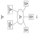
- FIG. 1is a schematic diagram of a health check monitoring process system.
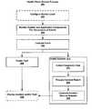
- FIG. 2is a process flow diagram of a health check monitoring process.
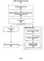
- FIG. 3is a schematic diagram of a health check monitoring process architecture during run time of incident creation.
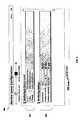
- FIG. 4is a view of a service level configuration user interface for the health check monitoring process and architecture of FIGS. 2 and 3 , respectively.
- FIG. 5is a view of a control center home page user interface for a health check monitoring process and architecture of FIGS. 2 and 3 , respectively.
- FIG. 6is a view of a system management user interface depicting an incident work list window for a health check monitoring process and architecture of FIGS. 2 and 3 , respectively.
- FIG. 7is a view of an incident instance user interface for a health check monitoring process and architecture of FIGS. 2 and 3 , respectively.
- FIG. 8is a view of an incident context data user interface for a health check monitoring process and architecture of FIGS. 2 and 3 , respectively.
- FIG. 9is a schematic diagram of a client system architecture suitable for the health check monitoring process system and techniques disclosed herein.
- FIG. 1is a schematic diagram of a system 100 that can utilize a health check monitoring process described herein.
- the system 100includes one or more client systems 102 , a back-end system 103 (e.g., an application provider system 104 and a service provider system 106 ), which are operatively coupled to a network 108 , such as the Internet, an intranet, a local area network, an Ethernet, a wireless network, and/or a telephone network.
- the application provideris the provider (manufactuer) of the enterprise software.
- the service providerprovides services for the enterprise software (e.g., user and system support, implementation service, etc.)
- the client systems 102can be any systems that run software.
- the softwarecan be a single application or an operating system, or a collection of software applications or software components that perform various tasks in a larger system or application, such as a business application suite, such as customer relationship management (CRM), business administration, financial, and manufacturing software.
- CRMcustomer relationship management
- the system 100can utilize a health check monitoring process embedded in one or more client systems 102 to constantly monitor the system and application components of the client systems 102 and create incidents and/or administration tasks if a critical situation is detected.
- a health check monitoring processembedded in one or more client systems 102 to constantly monitor the system and application components of the client systems 102 and create incidents and/or administration tasks if a critical situation is detected.
- the incidentsare provided to users, such as IT administrators, with instant access to context or diagnostic information to resolve or elevate the incident.
- Incidentscan be generated automatically after detection of a change in the system or the application components (e.g., a change in system or application component activity, a monitored performance value exceeding a pre-defined threshold, or a change in system or application component status, such as a queue overflow that stops a business process, etc.)
- the health check monitoring processcan be embedded in or more of the client systems 102 and is described more fully with reference to FIGS. 2-8 .
- One or more of the client systems 102also can include other embedded services, including but not limited to an integrated operations handbook, software maintenance management, incident processing and management (embedded support), and safeguarding.
- the integrated operations handbookcan include automated task and incident handling and a central administration console for operational management.
- Each task in the integrated operations handbookis associated with specific details of handling the task, such as when the task has to be performed (event based or time based), the responsible person (role), documentation on the task, and information on the service level agreement.
- a guided activity transactione.g., a wizard, may be provided to help a user perform an administration task, which guides the user through a defined activity.
- the incident processing and management servicecan provide end user support for incidents created by the health check monitoring process or the user and provide end user support and automated context collection for resolving incidents created by an end user.
- An end usercan manually create an incident through a support application, which can be invoked from any application screen to report a malfunction in the application or the user can use a support button, for example, in a self service view of a control center user interface.
- system 100is exemplary and other configurations, arrangements and network topologies for system 100 are possible, including more or fewer clients 102 and/or multiple back-end systems 103 .
- the application provider system 104 and/or the service provider system 106are/is integrated with the client systems 102 through the network 108 , which can be configured to facilitate continuous or periodic data exchange between the systems 104 , 106 and the client systems 102 using known networking protocols, such as TCP/IP and HTTP.
- an application provider system 104need not be used in system 100 .
- a service provider system 106need not be used in alternative variations of system 100 .
- system configuration information associated with the client systems 102is transmitted to the back-end system(s) 103 .
- the back-end system(s) 103request(s) system configuration information from the client systems 102 on a scheduled basis using, for example, a polling scheme.
- the client systems 102send information to the back-end system(s) 103 continuously or periodically, or in response to one or more events, for example notification of an incident or administration task.
- FIG. 2is a flow diagram of a health check monitoring process 200 .
- the process 200either continually or periodically checks the system and application components residing in a client system 102 and creates incidents and/or administration tasks if a critical situation is detected.
- an operator of a client systeme.g., an IT administrator
- the operatormay define the schedule that the process 200 is performed, e.g., constantly or periodically, such as every hour or daily.
- Step 202is performed during configuration time, i.e., once the operator configures the service level, he or she does not have to reconfigure the service level to initiate process 200 unless the operator desires to change the schedule or other service level information. Thus, during run-time of process 200 , step 202 is typically not performed as the operator has already set the service level during design time.
- the process 200begins in accordance with the pre-defined schedule, e.g., hourly or daily, set by the operator of a client system (e.g., an IT administrator) during service level configuration 202 . In other implementations, the process 200 begins when initiated by the operator.
- a client systeme.g., an IT administrator
- the process 200begins when initiated by the operator.
- the system and application components of the client system 102are monitored for the occurrence of any events.
- An eventfor example, is a change in system or application status or a system or an application performance value exceeding a threshold. Monitored events are stored and pushed to an evaluation engine, such as an event classification engine of a health check monitor, where, at 206 , the pushed events are evaluated.
- process 200when initiated may start at 206 , as 202 can occur separately from process 200 .
- itmay be desired to monitor the system and application components of the client system 102 constantly and not require the execution of the monitoring to be tied to the initiation schedule of process 200 .
- the evaluation of events, at 206may include two processes.
- each eventcan be routed based on rule logic (e.g., AND, OR, NOT AND, etc.), which, e.g., may be retrieved from a rules catalog of an integrated electronic operations hand book, which also includes other data storages, such as a task catalog and configuration data.
- rule logice.g., AND, OR, NOT AND, etc.
- the rules logicmay include scenarios, such as “if A AND B then C,” or “if A AND B, then NOT C.”
- the rules-based classification and routingcan include time dependent rules logic, such as “if A happens more than B times in C seconds, then D” or “if A happens AND NOT B happens within the next C seconds, then D.”
- the rules logiccan also include logic that classifies and routes an event based on severity and system impact, such as for an evaluation of a single event regarding its attributes in point in time.
- the rules logiccan include logic that classifies and routes events based on an evaluation of a single event according to the frequency of its occurrence.
- the rules logicfurther can include logic that classifies and routes different events occurring at the same time, which may be useful to identify the actual system status. For example, if a certain server does not respond and the corresponding network link indicates a network failure, then the actual problem is more likely a network issue rather than a service problem. This information can be used in order to trigger an appropriate system analysis.
- the rules logicalso can include logic that classifies and routes multiple events occurring over a period of time.
- a database response timeexceeds a certain threshold, which causes the generation of an event. But say, e.g., the event occurs only during the night while a time-consuming batch job is running. As a result, the rules-based classification and routing process may determine that the event need not be routed for further processing, e.g., by the second process of the evaluation 206 ). As another example, assume the database time exceeds a certain threshold several times, and the response time values increase over time during productive working hours. As a result, the rules-based classification and routing process may determine that the event needs to be routed for further processing, e.g., by the second process of the evaluation 206 . Typically, these routed events are critical system events from the application components.
- the rules catalog(data storage) can be maintained by the client system 102 , the application service provider system 104 , and/or the service provider system 106 .
- the first processis designed to handle the processing of a high throughput of events in a short time frame. As a consequence, the analysis at his level is not as detailed as may be required for the eventual resolution of a routed event.
- the second processis provided, which can provide more detailed analysis of each rule-based routed event.
- the first processcan occur locally in each client system 102 , while the second process can occur on a central client system 102 .
- each rule-based routed eventtriggers the execution of the second process of 206 .
- the second process of 206retrieves the routed event input (e.g., response time values, file system usage, CPU usage, etc.) and determines whether the routed event should be classified as an incident or an administration task.
- the routed event inpute.g., response time values, file system usage, CPU usage, etc.
- additional information about the routed eventmay be desired and can be retrieved from the system and application components associated with the event in order to determine whether the routed event should be classified as an incident or an administration task.
- the tasks which are necessary to analyze and resolve the eventare selected from, e.g., a task catalog (data storage) of a integrated electronic operations handbook, and processed to determine whether to classify the routed event as an incident or an administration task. If the tasks necessary to analyze the event are located, the event is classified as an administration task; otherwise the event is classified as an incident.
- a task catalogdata storage
- classifying the generated event as either an incident or an administration taskcan be based on predefined criteria, as provided by the task catalog of the integrated operations handbook.
- the task storageincludes predefined task events and can also include other information, such as task schedules, task responsibilities, and service level agreement data.
- the task storagedefines the responsible person for processing the task event.
- evaluating whether a routed event should be classified as an incident or taskcan be accomplished by searching the task storage of the operations handbook to determine if the routed event is listed in the operations handbook. If the generated event is not listed, then the generated event can be classified as an incident. If the generated event is listed, then the generated event can be classified as an administration task.
- an administration taskis created and associated context data is provided with the administration task.
- an administration taskcan be time-based triggered, e.g., periodic administration task or a combination of time-based triggered and event-based triggered (step 208 ).
- the created administration taskmay be optionally displayed, e.g., in user interfaces as described in FIGS. 5 and 6 for use during task management.
- an incidentis created, and, at 218 , may be optionally displayed in a service desk environment, e.g., in user interfaces described in FIGS. 5-8 .
- the context (or diagnostic) data associated with the incidentis automatically collected.
- the context or diagnostic datamay include, e.g., technical and application information, that is usually required to resolve the incident.
- the context datacan include, e.g., relevant system and application information from all architectural layers, such as a user interface layer, enterprise service layer, a business object layer and a system layer.
- the context datais automatically collected, at or near the time the event, which caused the creation of the incident, occurred, the state of the system or application components causing the incident is preserved (unlike conventional systems in which an operator may attempt to resolve the incident after the associated log files or other system or application component context information may have already been deleted).
- an incident reportis generated, which provides an explanation of the why the incident was triggered with the collected context data.
- an incident service requestis generated, typically by a service desk, such as a Customer Relationship Management (CRM) system residing on an application platform within the client system 102 .
- the service deskreceives the incident report, stores the report, and generates the service request.
- the incident service requestmay then be optionally displayed in a user interface as described in FIGS. 5-8 so that an operator or other end user can be visually notified of the incident service request and track the status of the incident service request.
- FIG. 3is a schematic diagram of a health check monitoring process architecture 300 illustrating run time incident creation and notification.
- the architecture 300includes one or more software layers, each including one or more software components for performing various task associated with the health check monitoring process 200 .
- the software layersinclude a user interface layer 302 , an application platform layer 304 , a process integration layer 306 , a data packaging layer 308 , a scheduler 330 , services delivery layer 310 , a services landscape layer 328 , and a system and application components layer 312 .
- the architecture 300will be explained in context with a run-time creation of an incident.
- the scheduler 330dictates when the health check monitoring process is activated, unless overridden by an operator or user-initiated execution of the health check monitoring process. If the scheduler 330 has been configured to run the health check monitoring process every minute, for example, then at the designated time, the scheduler 330 causes the health check monitor 332 in the services delivery layer 310 to retrieve the system configuration 329 from the services landscape layer 328 . Alternatively, the system configuration 329 may be pushed to the health check monitor 332 upon notification that the health check monitor has been initiated. In some implementations, the health check monitoring process may be constantly running 24 hours a day, 7 days a week.
- the system configuration information 329includes system operational parameters of the system and application components, such as generated system events and performance values. Based on the retrieved or pushed system configuration information 329 , the health check monitor 332 evaluates the operational parameters (e.g., generated events) as described in step 206 of FIG. 2 . In this implementation, the health check monitor 332 determines the generated event is an incident and initiates the creation of the incident. That is, the health check monitor 332 informs the context collection 324 in the data packaging layer 308 . Based on the incident, the context collection 324 automatically collects context (or diagnostic) data that is needed to resolve the incident The context data is provided to the software problem report 326 in the data packaging layer, which generates an incident report and stores the context data.
- the operational parameterse.g., generated events
- the message based integration (in) 320 in the process integration layer 306receives the incident report and context data, other incident reports if generated, and messages from the back-end system(s) 103 , such as incident handling or management activities (embedded support), such as data related to resolution of an incident.
- the message based integration (in)queues the incident reports and messages and provides it to the service request 318 in the service desk 308 (e.g., a CRM system), which resides in the application platform layer 304 .
- the service desk 308stores the incident report in the service request 318 and can attach the context data to the service request 318 , which may be provided to the user interface 314 in the user interface layer 302 .
- the processing of the software problem report 326 and the processing of the service request 318may reside in different client systems 102 , which is possible because of the message-based integration components 320 in the process integration layer 306 .
- the message based integration (out) 320 in the process integration layer 306queues outbound messages to the back-end system(s) 103 , e.g., where the service level agreement requires the application provider 104 and/or the service provider system 106 to monitor the system and application components of the client system 102 .
- the outbound messagesmay concern notification messages of the created incidents with the context data attached.
- the user interface layer 302includes various software components for generating a user interface 314 , including the screen shots shown in FIGS. 4-8 , and presenting the user interface 314 at the client system 102 , including the service request (i.e., the incident and context data).
- the user interface 314is presented as a web page which is served by a web server at the back-end system(s) 103 , which can then be viewed through a browser (e.g., Microsoft Internet Explorer®).
- an application or service running on the client system 102generates the user interface 314 using information generated within the client system 102 and/or the back-end system(s) 103 , which can be accessed through an application program interface (API) or other hook into the back-end system(s) 103 (e.g., a web portal).
- APIapplication program interface
- the architecture 300is exemplary, and other architectures can be used that have more or fewer components or layers.
- the various components of the architecture 300can be located at the client system 102 and/or back-end system(s) 103 .
- the architecture 300is implemented by a single program or application or by one or more components of an operating system on the client system 102 .
- FIGS. 4-8are screen shots of an implementation of a user interface (UI) for managing incident generation using the health check monitoring process and architecture shown in FIGS. 2 and 3 , respectively.
- FIGS. 4-8are described from the perspective of a fictitious IT administrator named “Jeff Goldblume.”
- the UIs shown in FIGS. 4-8are exemplary, as other UIs can be used as desired, including more or fewer UIs with various views, numbers and types of user interface elements, such as links, controls, search boxes, buttons, navigation bars, filters, and menus.
- FIG. 4is a screen shot of a service level configuration user interface 400 for the health check monitoring process and architecture of FIGS. 2 and 3 , respectively.
- Application service providerstypically define levels of system service and responsibility using service level agreements (SLA) with its customers.
- SLAservice level agreements
- the IT administrator of the customermay configure the health check monitoring process using information from the customer's SLA.
- the IT administrator “Jeff”may log onto the service level configuration UI 400 to set the monitoring and service level 402 and the monitoring settings 404 .
- the monitoring and service levels 402can include, for example, a “Gold” advanced monitoring services, a “Silver” medium monitoring services and a “Bronze” basic monitoring services. As seen in FIG. 4 , the “Gold” services has been selected.
- the monitoring settings 404can include, for example, service hours 406 , working hours local IT 408 and monitoring organization 410 .
- service hours 406can be 24 hours a day, 7 days a week. He set the working hours local IT 408 to be Monday through Friday, from 8 a.m. to 6 p.m.
- Jeffalso set the monitoring organization 410 to be a service provider called “Partner BBS.” Jeff can use his mouse cursor 412 to click on a “Next” button, which results in the display of a configure responsibilities UI (not shown), where Jeff may configure the responsible party for handling certain levels of incidents and tasks.
- FIG. 5is a screen shot of a control center user interface 500 for a health check monitoring process and architecture of FIGS. 2 and 3 , respectively.
- the control center user interface 500can be the initial starting point for an end user, such as an IT administrator, after logon.
- the user interfacepresents summarized information from all work centers assigned to the end user.
- the user interface 500includes a My Home view, a News view, a Work Inbox view, a Calendar view, a Reporting view, and a Self-Service view.
- the My Home viewis the first screen an end user sees after login.
- the Work Inbox viewcontains alerts and notifications in an e-mail inbox list.
- the work inboxincludes system events and administrations tasks that are urgent, vary import, escalated or overdue.
- the Reporting viewcontains all reports available in the different work centers.
- the News viewcontains, among other company news, a system news page, where IT administrators can post important information about the system status.
- the System News page in the News viewcan be available to every user.
- the Self-Service viewcontains, among other self-service applications, an application where every user can create a problem message, e.g., an incident or request a service, e.g., for a change of authorization in the system) from the IT department.
- the service request application in the Self-Service viewcan be available to every user.
- the IT administratorThe IT administrator, Jeff logs onto “home” 512 page after logon, and uses his mouse cursor 512 to click on a “My Home” view button, which enables Jeff to view a system overview of his environment, including Alerts & Notifications monitor 502 , Workload monitor 504 , System Overview monitor 506 , and Company News monitor 508 .
- Listed under the Alerts & Notifications monitor 504are categories Alerts and Notifications. In this example, there are no alerts and notifications.
- Listed under the Workload monitor 504are categories, including, e.g., unassigned incidents, new patches & updates, my team's incidents and new administration tasks. In this example, there are eleven unassigned incidents, which are indicated by the number 11 in parenthesis. There are five incidents noted for my team's incidents and two new administrative tasks.
- the Company News monitor 508can be used to provide a summary of recent company information, such as human resources notices or meeting announcements.
- the System Overview monitor 506provides a summary of the system and includes monitors, such as an incident overview monitor 508 , a task overview monitor, a system performance monitor, a news from SAP monitor and a customer surveys monitor.
- the incident overview monitor 508includes categories such as open user incidents, open system incidents, forwarded to SAP (e.g., an application provider), and action required. Each of these categories can be associated with a value, rating, and trend.
- the ratingis color coded, so that Jeff can quickly determine the status based on the color.
- An example color coding schemecould be green for normal and red for error or problem.
- the trendis represented by an arrow icon oriented in various positions, so that Jeff can quickly determine the trend based on historical data associated with that particular category.
- An example orientation schemecould be an arrow slanted upward for a trend increase, an arrow oriented in a horizontal state for a neutral trend, and an arrow slanted downward for a trend decrease.
- a system management UI 600is displayed as shown in FIG. 6 .
- the system management UI 600includes views including, e.g., overview, incidents, tasks, backup & recovery, user & access, expert tools, job scheduling, output management and reports.
- Jeffuses his cursor 612 to select the “incidents” button 610 that is associated with the incidents category to view a list of the incidents (e.g., active, pending and resolved incidents), which causes the display of a incident work list window 602 , which includes an incident work list 604 and incident information 608 concerning a selected incident 606 .
- the incident information 608includes, e.g., an incident number associated with the incident 606 .
- the incident numberis “321002101.”
- Jeffcan view more detailed information about a specific incident (whether generated by the health service described herein or a user-initiated incident).
- FIG. 7One such implementation is shown in FIG. 7 .
- FIG. 7is a screen shot of an incident instance user interface 700 for a health check monitoring process and architecture of FIGS. 2 and 3 , respectively.
- the user interface 700illustrates one implementation of depicting detailed information concerning a particular incident 702 , which was user created.
- the incident 702can have a incident number associated with it that can be generated by a service desk for ease of tracking the incidents.
- the incident 702has a tracking number “500006478.”
- the user interface 700includes various categories, which are located on the left side of the screen and include, e.g., main, assigned solutions, perform analysis, context data, time reporting and action log.
- Jeffcan select the “main” button with his cursor 612 .
- an incident details window 704is displayed.
- the incident details window 704includes an incident details section 706 , a context data section 708 , a requester information section 710 , and a support request message section 714 .
- the incident details section 706may include information relating to a status, a subject, a category, a sub-category, an initial response by date, a resolution by date, a priority, a responsible party for handling the incident, a support group and an escalated on date.
- the “sub-category” informationnotes that the incident 702 is user created.
- the requestor information section 710may include information relating to a company which made the service request, a name of the contact person at the company, a telephone number and an e-mail of the contact person.
- the support request message section 714provides a message history relating to the incident 702 .
- the context data section 708may include information such as the transaction type, the screen where incident occurred, the screen number and the program in which the incident occurred, the release number of the program and whether the program is Unicode or not. Jeff may obtain more detailed context data by selecting the “context data” button 716 of the incident instance UI 700 .
- FIG. 8is a screen shot of an incident context data user interface 800 for a health check monitoring process and architecture of FIGS. 2 and 3 , respectively.
- User interface 800may be displayed, for example, in response to Jeff selecting the “context data” button 716 of FIG. 7 .
- the context data 802is related to an incident that different than the incident 702 of FIG. 7 .
- the user interface 800includes all the context (diagnostic) data, e.g., technical and application information, that is usually required to resolve the incident.
- the context datacan include, e.g., relevant system and application information from all architectural layers, such as a user interface layer, enterprise service layer, a business object layer and a system layer.
- the user interface 800has two views—a content view 804 and a provider properties view 806 .
- the content view 804includes a snap-shot of the log files and system information 806 associated with the incident, which was previously collected and stored.
- the provider properties view 806may include, e.g., detailed information about system and application components providing context data.
- FIG. 9is a schematic diagram of a client system architecture 900 suitable for the heath check techniques disclosed herein.
- the architecture 900includes one or more processors 902 (e.g., CPU), a display device 904 , one or more network interfaces 906 (e.g., an Ethernet card), one or more input devices 908 (e.g., a mouse and/or a keyboard) and one or more computer-readable mediums 912 .
- processors 902e.g., CPU
- display device 904e.g., a display device 904
- network interfaces 906e.g., an Ethernet card
- input devices 908e.g., a mouse and/or a keyboard
- computer-readable mediums 912e.g., a mouse and/or a keyboard
- buses 914e.g., EISA and/or PCI
- computer-readable mediumrefers to any medium that participates in providing instructions to the processor 902 for execution, including without limitation, non-volatile media (e.g., optical, NOR or NAND flash, ROM or magnetic disks), volatile media (e.g., RAM) and transmission media.
- Transmission mediaincludes, without limitation, coaxial cables, copper wire and fiber optics. Transmission media can also take the form of acoustic, light or radio frequency waves.
- the computer-readable medium 912further includes an operating system 916 (e.g., Windows®, Unix or Linux), a network communications module 918 , a browser 920 , a software maintenance module 922 , system configuration information 924 , a work list 926 , a health check module 928 , and one or more applications 930 (e.g., a suite of business applications).
- the operating system 916can be multi-user, multiprocessing, multitasking, multithreading, real-time and the like.
- the operating system 916performs basic tasks, including but not limited to: recognizing input from input devices 908 ; sending output to the display device 904 ; keeping track of files and directories on storage devices 912 ; controlling peripheral devices (e.g., disk drives, printers, etc.); and managing traffic on the one or more buses 914 .
- the network communications module 918includes various components for establishing and maintaining network connections (e.g., software for implementing communication protocols, such as TCP/IP, HTTP and Ethernet).
- the browser 920is used to display the various user interfaces shown in FIGS. 4-8 .
- the software maintenance module 920provides performs software maintenance and updating processes.
- the system configuration information 924includes configuration data describing the status of the system and application components of client system 102 .
- the incident work list 926is described with respect to FIG. 6 .
- the health check module 928provides various software components for performing processes described with respect to FIGS. 1-8 . In some implementations, some or all of the processes performed by the health check module 928 can be integrated into the operating system 916 .
- Applications 930can include any software applications, such as business applications, word processors, email applications, Instant Messaging, media players, and telephony software.
- implementations of the subject matter described hereinmay be realized in digital electronic circuitry, integrated circuitry, specially designed ASICs (application specific integrated circuits), computer hardware, firmware, software, and/or combinations thereof.
- ASICsapplication specific integrated circuits
- These various implementationsmay include implementation in one or more computer programs that are executable and/or interpretable on a programmable system including at least one programmable processor, which may be special or general purpose, coupled to receive data and instructions from, and to transmit data and instructions to, a storage system, at least one input device, and at least one output device.
- the subject matter described hereinmay be implemented on a computer having a display device (e.g., a CRT (cathode ray tube) or LCD (liquid crystal display) monitor) for displaying information to the user and a keyboard and a pointing device (e.g., a mouse or a trackball) by which the user may provide input to the computer.
- a display devicee.g., a CRT (cathode ray tube) or LCD (liquid crystal display) monitor
- a keyboard and a pointing devicee.g., a mouse or a trackball
- Other kinds of devicesmay be used to provide for interaction with a user as well; for example, feedback provided to the user may be any form of sensory feedback (e.g., visual feedback, auditory feedback, or tactile feedback); and input from the user may be received in any form, including acoustic, speech, or tactile input.
- the subject matter described hereinmay be implemented in a computing system that includes a back-end component (e.g., as a data server), or that includes a middleware component (e.g., an application server), or that includes a front-end component (e.g., a client computer having a graphical user interface or a Web browser through which a user may interact with an implementation of the subject matter described herein), or any combination of such back-end, middleware, or front-end components.
- the components of the systemmay be interconnected by any form or medium of digital data communication (e.g., a communication network). Examples of communication networks include a local area network (“LAN”), a wide area network (“WAN”), and the Internet.
- LANlocal area network
- WANwide area network
- the Internetthe global information network
- the computing systemmay include clients and servers.
- a client and serverare generally remote from each other and typically interact through a communication network.
- the relationship of client and serverarises by virtue of computer programs running on the respective computers and having a client-server relationship to each other.
Landscapes
- Engineering & Computer Science (AREA)
- Theoretical Computer Science (AREA)
- General Engineering & Computer Science (AREA)
- Quality & Reliability (AREA)
- Physics & Mathematics (AREA)
- General Physics & Mathematics (AREA)
- Computer Hardware Design (AREA)
- Debugging And Monitoring (AREA)
Abstract
Description
Claims (20)
Priority Applications (1)
| Application Number | Priority Date | Filing Date | Title |
|---|---|---|---|
| US11/322,890US7979733B2 (en) | 2005-12-30 | 2005-12-30 | Health check monitoring process |
Applications Claiming Priority (1)
| Application Number | Priority Date | Filing Date | Title |
|---|---|---|---|
| US11/322,890US7979733B2 (en) | 2005-12-30 | 2005-12-30 | Health check monitoring process |
Publications (2)
| Publication Number | Publication Date |
|---|---|
| US20070174716A1 US20070174716A1 (en) | 2007-07-26 |
| US7979733B2true US7979733B2 (en) | 2011-07-12 |
Family
ID=38287036
Family Applications (1)
| Application Number | Title | Priority Date | Filing Date |
|---|---|---|---|
| US11/322,890Active2027-05-24US7979733B2 (en) | 2005-12-30 | 2005-12-30 | Health check monitoring process |
Country Status (1)
| Country | Link |
|---|---|
| US (1) | US7979733B2 (en) |
Cited By (20)
| Publication number | Priority date | Publication date | Assignee | Title |
|---|---|---|---|---|
| US8521153B1 (en) | 2012-06-18 | 2013-08-27 | International Business Machines Corporation | Using the maintenance channel in a mobile data network to provide subscriber data when a cache miss occurs |
| US8607074B2 (en) | 2011-12-19 | 2013-12-10 | International Business Machines Corporation | States for breakout appliance in a mobile data network |
| US8611209B2 (en) | 2011-12-19 | 2013-12-17 | International Business Machines Corporation | Autonomic error recovery for a data breakout appliance at the edge of a mobile data network |
| US8693309B2 (en) | 2011-11-16 | 2014-04-08 | International Business Machines Corporation | Fail to wire removable module for network communication link |
| US8724455B2 (en) | 2012-01-20 | 2014-05-13 | International Business Machines Corporation | Distributed control of a fail-to-wire switch for a network communication link |
| US8761827B2 (en) | 2011-12-21 | 2014-06-24 | International Business Machines Corporation | Layered control of service interface for a breakout component in a mobile data network |
| US8769615B2 (en) | 2011-12-19 | 2014-07-01 | International Business Machines Corporation | Key storage and retrieval in a breakout component at the edge of a mobile data network |
| US8776182B2 (en) | 2011-12-31 | 2014-07-08 | International Business Machines Corporation | Secure boot of a data breakout appliance with multiple subsystems at the edge of a mobile data network |
| US8793504B2 (en) | 2012-02-22 | 2014-07-29 | International Business Machines Corporation | Validating a system with multiple subsystems using trusted platform modules and virtual platform modules |
| US8837318B2 (en) | 2011-09-15 | 2014-09-16 | International Business Machines Corporation | Mobile network services in a mobile data network |
| US8873382B2 (en) | 2012-07-06 | 2014-10-28 | International Business Machines Corporation | Overload detection and handling in a data breakout appliance at the edge of a mobile data network |
| US8873495B2 (en) | 2011-12-19 | 2014-10-28 | International Business Machines Corporation | Push based services in a mobile data network with data breakout at the edge |
| US8971192B2 (en) | 2011-11-16 | 2015-03-03 | International Business Machines Corporation | Data breakout at the edge of a mobile data network |
| US20150128064A1 (en)* | 2005-03-14 | 2015-05-07 | Seven Networks, Inc. | Intelligent rendering of information in a limited display environment |
| US9030944B2 (en) | 2012-08-02 | 2015-05-12 | International Business Machines Corporation | Aggregated appliance in a mobile data network |
| US9042864B2 (en) | 2011-12-19 | 2015-05-26 | International Business Machines Corporation | Appliance in a mobile data network that spans multiple enclosures |
| US20160042358A1 (en)* | 2014-08-11 | 2016-02-11 | International Business Machines Corporation | Mapping user actions to historical paths to determine a predicted endpoint |
| US20160154692A1 (en)* | 2014-11-28 | 2016-06-02 | Software Ag | Systems and/or methods for handling erroneous events in complex event processing (cep) applications |
| US9775158B2 (en) | 2011-11-16 | 2017-09-26 | International Business Machines Corporation | Data caching at the edge of a mobile data network |
| US10055277B1 (en) | 2015-09-30 | 2018-08-21 | Amdocs Development Limited | System, method, and computer program for performing health checks on a system including a plurality of heterogeneous system components |
Families Citing this family (25)
| Publication number | Priority date | Publication date | Assignee | Title |
|---|---|---|---|---|
| KR20070108432A (en)* | 2006-01-23 | 2007-11-12 | 엘지전자 주식회사 | Device Management Scheduling Method |
| US8104037B2 (en) | 2006-01-23 | 2012-01-24 | Lg Electronics Inc. | Terminal and method for performing device management scheduled based on threshold |
| US7523357B2 (en)* | 2006-01-24 | 2009-04-21 | International Business Machines Corporation | Monitoring system and method |
| KR101349805B1 (en)* | 2006-01-25 | 2014-01-10 | 엘지전자 주식회사 | Method for scheduling device managemnt using trap mechanism and terminal thereof |
| US20070260932A1 (en)* | 2006-04-11 | 2007-11-08 | Ryan Prichard | Event log management system |
| US20080126162A1 (en)* | 2006-11-28 | 2008-05-29 | Angus Keith W | Integrated activity logging and incident reporting |
| US8935288B2 (en)* | 2007-03-28 | 2015-01-13 | Oracle International Corporation | User specific logs in multi-user applications |
| US7954014B2 (en)* | 2007-09-18 | 2011-05-31 | Sap Ag | Health check framework for enterprise systems |
| US8448015B2 (en)* | 2008-06-17 | 2013-05-21 | My Computer Works, Inc. | Remote computer diagnostic system and method |
| US8065315B2 (en)* | 2008-08-27 | 2011-11-22 | Sap Ag | Solution search for software support |
| US7917815B2 (en)* | 2008-08-27 | 2011-03-29 | Sap Ag | Multi-layer context parsing and incident model construction for software support |
| JP5156838B2 (en)* | 2008-10-27 | 2013-03-06 | 株式会社日立製作所 | Resource management method and embedded device |
| US8281322B2 (en) | 2008-11-18 | 2012-10-02 | At&T Intellectual Property I, L.P. | Adaptive application interface management |
| US8271834B2 (en)* | 2008-12-15 | 2012-09-18 | International Business Machines Corporation | Method and system for providing immunity to computers |
| TWI388979B (en)* | 2009-09-18 | 2013-03-11 | Asustek Comp Inc | Computer system and monitoring device |
| US8914502B2 (en)* | 2011-09-27 | 2014-12-16 | Oracle International Corporation | System and method for dynamic discovery of origin servers in a traffic director environment |
| US9247004B2 (en)* | 2011-10-25 | 2016-01-26 | Vital Connect, Inc. | System and method for reliable and scalable health monitoring |
| JP6048089B2 (en)* | 2011-12-26 | 2016-12-21 | 株式会社リコー | Information processing apparatus and program |
| US9223673B1 (en) | 2013-04-08 | 2015-12-29 | Amazon Technologies, Inc. | Custom host errors definition service |
| US9092332B2 (en)* | 2013-05-02 | 2015-07-28 | Microsoft Technology Licensing, Llc | Activity based sampling of diagnostics data |
| US20150161236A1 (en)* | 2013-12-05 | 2015-06-11 | Lenovo (Singapore) Pte. Ltd. | Recording context for conducting searches |
| IN2014MU00662A (en)* | 2014-02-25 | 2015-10-23 | Tata Consultancy Services Ltd | |
| CN110427407A (en)* | 2018-04-28 | 2019-11-08 | 上海亨通光电科技有限公司 | A kind of design method of precisely quick-acting management systems |
| CN111212102A (en)* | 2019-11-29 | 2020-05-29 | 泰康保险集团股份有限公司 | Task push management method, device and system, storage medium and electronic equipment |
| US12353314B2 (en)* | 2022-04-13 | 2025-07-08 | Jpmorgan Chase Bank, N.A. | Method and system for automated application management |
Citations (66)
| Publication number | Priority date | Publication date | Assignee | Title |
|---|---|---|---|---|
| US5436966A (en) | 1994-05-05 | 1995-07-25 | At&T Corp. | Interface for handling event messages generated by telecommunications switches with automatic call distribution capability |
| US6177932B1 (en) | 1998-08-21 | 2001-01-23 | Kana Communications, Inc. | Method and apparatus for network based customer service |
| US6199068B1 (en) | 1997-09-11 | 2001-03-06 | Abb Power T&D Company Inc. | Mapping interface for a distributed server to translate between dissimilar file formats |
| US6230287B1 (en) | 1997-09-04 | 2001-05-08 | Mitel Corporation | Web based help desk |
| US6272333B1 (en) | 1998-06-12 | 2001-08-07 | Motorola, Inc. | Method and apparatus in a wireless communication system for controlling a delivery of data |
| US6289378B1 (en) | 1998-10-20 | 2001-09-11 | Triactive Technologies, L.L.C. | Web browser remote computer management system |
| US6304893B1 (en) | 1996-07-01 | 2001-10-16 | Sun Microsystems, Inc. | Object-oriented system, method and article of manufacture for a client-server event driven message framework in an interprise computing framework system |
| US6389426B1 (en) | 1999-02-09 | 2002-05-14 | Worldcom, Inc. | Central trouble ticket database and system and method for managing same to facilitate ticketing, trending, and tracking processes |
| US20020073355A1 (en)* | 2000-08-01 | 2002-06-13 | Qwest Communications International, Inc. | Proactive repair process in the xDSL network (with a VDSL focus) |
| US6424991B1 (en) | 1996-07-01 | 2002-07-23 | Sun Microsystems, Inc. | Object-oriented system, method and article of manufacture for a client-server communication framework |
| US20020103987A1 (en) | 2001-01-26 | 2002-08-01 | Jaffrey Syed Kamal H. | Computer system and method that eliminates the need for an operating system |
| US6434598B1 (en) | 1996-07-01 | 2002-08-13 | Sun Microsystems, Inc. | Object-oriented system, method and article of manufacture for a client-server graphical user interface (#9) framework in an interprise computing framework system |
| US20020138571A1 (en) | 2000-07-10 | 2002-09-26 | Jean-Marc Trinon | System and method of enterprise systems and business impact management |
| US20020165952A1 (en)* | 2000-10-20 | 2002-11-07 | Sewell James M. | Systems and methods for remote management of diagnostic devices and data associated therewith |
| US20020177910A1 (en)* | 2000-04-19 | 2002-11-28 | Quarterman John S. | Performance measurement system for large computer network |
| US20030051184A1 (en)* | 2001-08-30 | 2003-03-13 | International Business Machines Corporation | Method and apparatus in a data processing system for managing situations from correlated events |
| US20030056140A1 (en)* | 2000-05-05 | 2003-03-20 | Taylor David K. | Help desk systems and methods for use with communications networks |
| US20030061541A1 (en)* | 1999-06-03 | 2003-03-27 | Kaler Christopher G. | Method and apparatus for analyzing performance of data processing system |
| US20030067704A1 (en)* | 2001-09-21 | 2003-04-10 | Woo Arthur Cheumin | Data storage media having integrated environmental sensor |
| US20030110248A1 (en) | 2001-02-08 | 2003-06-12 | Ritche Scott D. | Automated service support of software distribution in a distributed computer network |
| US6598167B2 (en) | 1997-09-26 | 2003-07-22 | Worldcom, Inc. | Secure customer interface for web based data management |
| US20030144894A1 (en) | 2001-11-12 | 2003-07-31 | Robertson James A. | System and method for creating and managing survivable, service hosting networks |
| US6611955B1 (en)* | 1999-06-03 | 2003-08-26 | Swisscom Ag | Monitoring and testing middleware based application software |
| US20030189600A1 (en) | 2002-03-29 | 2003-10-09 | Prasad Gune | Defining an approval process for requests for approval |
| US6654915B1 (en)* | 2000-09-11 | 2003-11-25 | Unisys Corporation | Automatic fault management system utilizing electronic service requests |
| US20040015953A1 (en) | 2001-03-19 | 2004-01-22 | Vincent Jonathan M. | Automatically updating software components across network as needed |
| US6691159B1 (en) | 2000-02-24 | 2004-02-10 | General Electric Company | Web-based method and system for providing assistance to computer users |
| US20040044987A1 (en) | 2002-08-29 | 2004-03-04 | Prasad Kompalli | Rapid application integration |
| US6714976B1 (en)* | 1997-03-20 | 2004-03-30 | Concord Communications, Inc. | Systems and methods for monitoring distributed applications using diagnostic information |
| US6718489B1 (en)* | 2000-12-07 | 2004-04-06 | Unisys Corporation | Electronic service request generator for automatic fault management system |
| US20040078695A1 (en)* | 2002-05-14 | 2004-04-22 | Bowers Wayne J. | Capturing system error messages |
| US20040088404A1 (en) | 2002-11-01 | 2004-05-06 | Vikas Aggarwal | Administering users in a fault and performance monitoring system using distributed data gathering and storage |
| US20040117689A1 (en)* | 2002-12-12 | 2004-06-17 | International Business Machines Corporation | Method and system for diagnostic approach for fault isolation at device level on peripheral component interconnect (PCI) bus |
| US20040123304A1 (en) | 2002-12-18 | 2004-06-24 | International Business Machines Corporation | Method, apparatus, and program for associating related heterogeneous events in an event handler |
| US20040187103A1 (en) | 2003-03-17 | 2004-09-23 | Wickham Robert T. | Software updating system and method |
| US6799147B1 (en) | 2001-05-31 | 2004-09-28 | Sprint Communications Company L.P. | Enterprise integrated testing and performance monitoring software |
| US20040205374A1 (en)* | 2002-11-04 | 2004-10-14 | Poletto Massimiliano Antonio | Connection based anomaly detection |
| US20040230559A1 (en) | 1999-08-09 | 2004-11-18 | Mark Newman | Information processing device and information processing method |
| US6829734B1 (en) | 2000-04-04 | 2004-12-07 | International Business Machines Corporation | Method for discovering problem resolutions in a free form computer helpdesk data set |
| US20050021847A1 (en) | 2003-06-25 | 2005-01-27 | Rothman Michael A. | OS agnostic resource sharing across multiple computing platforms |
| US20050022177A1 (en) | 2000-05-25 | 2005-01-27 | Mccaleb Jed | Intelligent patch checker |
| US20050033625A1 (en)* | 2003-08-06 | 2005-02-10 | International Business Machines Corporation | Method, apparatus and program storage device for scheduling the performance of maintenance tasks to maintain a system environment |
| US20050038827A1 (en) | 2003-08-11 | 2005-02-17 | Hooks David Eugene | Systems and methods for automated computer support |
| US6859783B2 (en) | 1995-12-29 | 2005-02-22 | Worldcom, Inc. | Integrated interface for web based customer care and trouble management |
| US20050091640A1 (en)* | 2003-10-24 | 2005-04-28 | Mccollum Raymond W. | Rules definition language |
| US20050097396A1 (en) | 2003-10-20 | 2005-05-05 | International Business Machines Corporation | System and method for root cause linking of trouble tickets |
| US6892317B1 (en)* | 1999-12-16 | 2005-05-10 | Xerox Corporation | Systems and methods for failure prediction, diagnosis and remediation using data acquisition and feedback for a distributed electronic system |
| US20050144526A1 (en)* | 2003-12-10 | 2005-06-30 | Banko Stephen J. | Adaptive log file scanning utility |
| US20050172243A1 (en) | 1998-11-30 | 2005-08-04 | Sun Microsystems, Inc. | Method and apparatus for detecting device support in a graphical user interface |
| US20050273667A1 (en)* | 2004-05-21 | 2005-12-08 | Sandeep Shrivastava | Diagnostic instrumentation |
| US6985944B2 (en) | 2002-11-01 | 2006-01-10 | Fidelia Technology, Inc. | Distributing queries and combining query responses in a fault and performance monitoring system using distributed data gathering and storage |
| US7003502B1 (en) | 2001-07-17 | 2006-02-21 | Unisys Corporation | Method for knowledge management |
| US20060095392A1 (en)* | 2002-10-31 | 2006-05-04 | Thomas Arend | Identifying solutions to computer problems by expert system using contexts and distinguishing versions |
| US20060116981A1 (en) | 2004-11-30 | 2006-06-01 | Stefan Krimmel | Method and system for automated data collection and analysis of a computer system |
| US20060191007A1 (en) | 2005-02-24 | 2006-08-24 | Sanjiva Thielamay | Security force automation |
| US7225367B2 (en) | 2001-08-22 | 2007-05-29 | Genworth Financial, Inc. | Method and system for tracking errors |
| US7225139B1 (en) | 2000-06-27 | 2007-05-29 | Bellsouth Intellectual Property Corp | Trouble tracking system and method |
| US20070150812A1 (en) | 2005-12-23 | 2007-06-28 | Eazypaper Inc. | User support system integrating FAQ and helpdesk features |
| US20070162485A1 (en) | 2005-12-30 | 2007-07-12 | Tilmann Haeberle | Generating contextual support requests |
| US20070174731A1 (en) | 2005-12-30 | 2007-07-26 | Tilmann Haeberle | Contextual enterprise software support tools |
| US20070203712A1 (en) | 2002-03-29 | 2007-08-30 | Mark Sunday | Screening electronic service requests |
| US7305465B2 (en) | 2000-11-15 | 2007-12-04 | Robert Wing | Collecting appliance problem information over network and providing remote technical support to deliver appliance fix information to an end user |
| US7340038B2 (en) | 2003-03-14 | 2008-03-04 | At&T Bls Intellectual Property, Inc. | Systems, methods and computer program products for automatically pushing a status change message as a result of repair services that are performed on a network |
| US20080056476A1 (en) | 2004-07-02 | 2008-03-06 | Greg Pounds | Method and Apparatus for Binding Multiple Profiles and Applications to a Single Device Through Network Control |
| US7366731B2 (en) | 2003-12-12 | 2008-04-29 | At&T Delaware Intellectual Property, Inc. | Trouble ticket assignment |
| US7516450B2 (en) | 2002-09-24 | 2009-04-07 | Ricoh Company, Ltd. | Remote management system, intermediary apparatus therefor, and method of updating software in the intermediary apparatus |
- 2005
- 2005-12-30USUS11/322,890patent/US7979733B2/enactiveActive
Patent Citations (69)
| Publication number | Priority date | Publication date | Assignee | Title |
|---|---|---|---|---|
| US5436966A (en) | 1994-05-05 | 1995-07-25 | At&T Corp. | Interface for handling event messages generated by telecommunications switches with automatic call distribution capability |
| US6859783B2 (en) | 1995-12-29 | 2005-02-22 | Worldcom, Inc. | Integrated interface for web based customer care and trouble management |
| US6434598B1 (en) | 1996-07-01 | 2002-08-13 | Sun Microsystems, Inc. | Object-oriented system, method and article of manufacture for a client-server graphical user interface (#9) framework in an interprise computing framework system |
| US6304893B1 (en) | 1996-07-01 | 2001-10-16 | Sun Microsystems, Inc. | Object-oriented system, method and article of manufacture for a client-server event driven message framework in an interprise computing framework system |
| US6424991B1 (en) | 1996-07-01 | 2002-07-23 | Sun Microsystems, Inc. | Object-oriented system, method and article of manufacture for a client-server communication framework |
| US6714976B1 (en)* | 1997-03-20 | 2004-03-30 | Concord Communications, Inc. | Systems and methods for monitoring distributed applications using diagnostic information |
| US6230287B1 (en) | 1997-09-04 | 2001-05-08 | Mitel Corporation | Web based help desk |
| US6199068B1 (en) | 1997-09-11 | 2001-03-06 | Abb Power T&D Company Inc. | Mapping interface for a distributed server to translate between dissimilar file formats |
| US6615258B1 (en) | 1997-09-26 | 2003-09-02 | Worldcom, Inc. | Integrated customer interface for web based data management |
| US6598167B2 (en) | 1997-09-26 | 2003-07-22 | Worldcom, Inc. | Secure customer interface for web based data management |
| US6272333B1 (en) | 1998-06-12 | 2001-08-07 | Motorola, Inc. | Method and apparatus in a wireless communication system for controlling a delivery of data |
| US6177932B1 (en) | 1998-08-21 | 2001-01-23 | Kana Communications, Inc. | Method and apparatus for network based customer service |
| US6289378B1 (en) | 1998-10-20 | 2001-09-11 | Triactive Technologies, L.L.C. | Web browser remote computer management system |
| US20050172243A1 (en) | 1998-11-30 | 2005-08-04 | Sun Microsystems, Inc. | Method and apparatus for detecting device support in a graphical user interface |
| US6930695B1 (en) | 1998-11-30 | 2005-08-16 | Sun Microsystems, Inc. | Method and apparatus for detecting device support in a graphical user interface |
| US6389426B1 (en) | 1999-02-09 | 2002-05-14 | Worldcom, Inc. | Central trouble ticket database and system and method for managing same to facilitate ticketing, trending, and tracking processes |
| US20030061541A1 (en)* | 1999-06-03 | 2003-03-27 | Kaler Christopher G. | Method and apparatus for analyzing performance of data processing system |
| US6611955B1 (en)* | 1999-06-03 | 2003-08-26 | Swisscom Ag | Monitoring and testing middleware based application software |
| US20040230559A1 (en) | 1999-08-09 | 2004-11-18 | Mark Newman | Information processing device and information processing method |
| US6892317B1 (en)* | 1999-12-16 | 2005-05-10 | Xerox Corporation | Systems and methods for failure prediction, diagnosis and remediation using data acquisition and feedback for a distributed electronic system |
| US6691159B1 (en) | 2000-02-24 | 2004-02-10 | General Electric Company | Web-based method and system for providing assistance to computer users |
| US6829734B1 (en) | 2000-04-04 | 2004-12-07 | International Business Machines Corporation | Method for discovering problem resolutions in a free form computer helpdesk data set |
| US20020177910A1 (en)* | 2000-04-19 | 2002-11-28 | Quarterman John S. | Performance measurement system for large computer network |
| US20030056140A1 (en)* | 2000-05-05 | 2003-03-20 | Taylor David K. | Help desk systems and methods for use with communications networks |
| US20050022177A1 (en) | 2000-05-25 | 2005-01-27 | Mccaleb Jed | Intelligent patch checker |
| US7225139B1 (en) | 2000-06-27 | 2007-05-29 | Bellsouth Intellectual Property Corp | Trouble tracking system and method |
| US20020138571A1 (en) | 2000-07-10 | 2002-09-26 | Jean-Marc Trinon | System and method of enterprise systems and business impact management |
| US20020073355A1 (en)* | 2000-08-01 | 2002-06-13 | Qwest Communications International, Inc. | Proactive repair process in the xDSL network (with a VDSL focus) |
| US20020087680A1 (en)* | 2000-08-01 | 2002-07-04 | Cerami Richard S. | Proactive service request management and measurement |
| US6654915B1 (en)* | 2000-09-11 | 2003-11-25 | Unisys Corporation | Automatic fault management system utilizing electronic service requests |
| US20020165952A1 (en)* | 2000-10-20 | 2002-11-07 | Sewell James M. | Systems and methods for remote management of diagnostic devices and data associated therewith |
| US7305465B2 (en) | 2000-11-15 | 2007-12-04 | Robert Wing | Collecting appliance problem information over network and providing remote technical support to deliver appliance fix information to an end user |
| US6718489B1 (en)* | 2000-12-07 | 2004-04-06 | Unisys Corporation | Electronic service request generator for automatic fault management system |
| US20020103987A1 (en) | 2001-01-26 | 2002-08-01 | Jaffrey Syed Kamal H. | Computer system and method that eliminates the need for an operating system |
| US20030110248A1 (en) | 2001-02-08 | 2003-06-12 | Ritche Scott D. | Automated service support of software distribution in a distributed computer network |
| US20040015953A1 (en) | 2001-03-19 | 2004-01-22 | Vincent Jonathan M. | Automatically updating software components across network as needed |
| US6799147B1 (en) | 2001-05-31 | 2004-09-28 | Sprint Communications Company L.P. | Enterprise integrated testing and performance monitoring software |
| US7003502B1 (en) | 2001-07-17 | 2006-02-21 | Unisys Corporation | Method for knowledge management |
| US7225367B2 (en) | 2001-08-22 | 2007-05-29 | Genworth Financial, Inc. | Method and system for tracking errors |
| US20030051184A1 (en)* | 2001-08-30 | 2003-03-13 | International Business Machines Corporation | Method and apparatus in a data processing system for managing situations from correlated events |
| US20030067704A1 (en)* | 2001-09-21 | 2003-04-10 | Woo Arthur Cheumin | Data storage media having integrated environmental sensor |
| US20030144894A1 (en) | 2001-11-12 | 2003-07-31 | Robertson James A. | System and method for creating and managing survivable, service hosting networks |
| US20030189600A1 (en) | 2002-03-29 | 2003-10-09 | Prasad Gune | Defining an approval process for requests for approval |
| US20070203712A1 (en) | 2002-03-29 | 2007-08-30 | Mark Sunday | Screening electronic service requests |
| US20040078695A1 (en)* | 2002-05-14 | 2004-04-22 | Bowers Wayne J. | Capturing system error messages |
| US20040044987A1 (en) | 2002-08-29 | 2004-03-04 | Prasad Kompalli | Rapid application integration |
| US7516450B2 (en) | 2002-09-24 | 2009-04-07 | Ricoh Company, Ltd. | Remote management system, intermediary apparatus therefor, and method of updating software in the intermediary apparatus |
| US20060095392A1 (en)* | 2002-10-31 | 2006-05-04 | Thomas Arend | Identifying solutions to computer problems by expert system using contexts and distinguishing versions |
| US20040088404A1 (en) | 2002-11-01 | 2004-05-06 | Vikas Aggarwal | Administering users in a fault and performance monitoring system using distributed data gathering and storage |
| US6985944B2 (en) | 2002-11-01 | 2006-01-10 | Fidelia Technology, Inc. | Distributing queries and combining query responses in a fault and performance monitoring system using distributed data gathering and storage |
| US20040205374A1 (en)* | 2002-11-04 | 2004-10-14 | Poletto Massimiliano Antonio | Connection based anomaly detection |
| US20040117689A1 (en)* | 2002-12-12 | 2004-06-17 | International Business Machines Corporation | Method and system for diagnostic approach for fault isolation at device level on peripheral component interconnect (PCI) bus |
| US20040123304A1 (en) | 2002-12-18 | 2004-06-24 | International Business Machines Corporation | Method, apparatus, and program for associating related heterogeneous events in an event handler |
| US7340038B2 (en) | 2003-03-14 | 2008-03-04 | At&T Bls Intellectual Property, Inc. | Systems, methods and computer program products for automatically pushing a status change message as a result of repair services that are performed on a network |
| US20040187103A1 (en) | 2003-03-17 | 2004-09-23 | Wickham Robert T. | Software updating system and method |
| US20050021847A1 (en) | 2003-06-25 | 2005-01-27 | Rothman Michael A. | OS agnostic resource sharing across multiple computing platforms |
| US20050033625A1 (en)* | 2003-08-06 | 2005-02-10 | International Business Machines Corporation | Method, apparatus and program storage device for scheduling the performance of maintenance tasks to maintain a system environment |
| US20050038827A1 (en) | 2003-08-11 | 2005-02-17 | Hooks David Eugene | Systems and methods for automated computer support |
| US20050097396A1 (en) | 2003-10-20 | 2005-05-05 | International Business Machines Corporation | System and method for root cause linking of trouble tickets |
| US20050091640A1 (en)* | 2003-10-24 | 2005-04-28 | Mccollum Raymond W. | Rules definition language |
| US20050144526A1 (en)* | 2003-12-10 | 2005-06-30 | Banko Stephen J. | Adaptive log file scanning utility |
| US7366731B2 (en) | 2003-12-12 | 2008-04-29 | At&T Delaware Intellectual Property, Inc. | Trouble ticket assignment |
| US20050273667A1 (en)* | 2004-05-21 | 2005-12-08 | Sandeep Shrivastava | Diagnostic instrumentation |
| US20080056476A1 (en) | 2004-07-02 | 2008-03-06 | Greg Pounds | Method and Apparatus for Binding Multiple Profiles and Applications to a Single Device Through Network Control |
| US20060116981A1 (en) | 2004-11-30 | 2006-06-01 | Stefan Krimmel | Method and system for automated data collection and analysis of a computer system |
| US20060191007A1 (en) | 2005-02-24 | 2006-08-24 | Sanjiva Thielamay | Security force automation |
| US20070150812A1 (en) | 2005-12-23 | 2007-06-28 | Eazypaper Inc. | User support system integrating FAQ and helpdesk features |
| US20070162485A1 (en) | 2005-12-30 | 2007-07-12 | Tilmann Haeberle | Generating contextual support requests |
| US20070174731A1 (en) | 2005-12-30 | 2007-07-26 | Tilmann Haeberle | Contextual enterprise software support tools |
Non-Patent Citations (4)
| Title |
|---|
| Notice of Allowance issued in U.S. Appl. No. 11/322,946 on Dec. 10, 2010; 7 pages. |
| Office Action issued in U.S. Appl. No. 11/322,946 on Mar. 29, 2010; 19 pages. |
| Office Action issued in U.S. Appl. No. 11/322,946 on Sep. 21, 2009; 19 pages. |
| SmarterTickets 1.x (SmarterTools.com), version 1.0.1561; released Apr. 10, 2004; 49 pages. |
Cited By (38)
| Publication number | Priority date | Publication date | Assignee | Title |
|---|---|---|---|---|
| US20150128064A1 (en)* | 2005-03-14 | 2015-05-07 | Seven Networks, Inc. | Intelligent rendering of information in a limited display environment |
| US9014023B2 (en) | 2011-09-15 | 2015-04-21 | International Business Machines Corporation | Mobile network services in a mobile data network |
| US8837318B2 (en) | 2011-09-15 | 2014-09-16 | International Business Machines Corporation | Mobile network services in a mobile data network |
| US10021696B2 (en) | 2011-11-16 | 2018-07-10 | International Business Machines Corporation | Data caching at the edge of a mobile data network |
| US8971192B2 (en) | 2011-11-16 | 2015-03-03 | International Business Machines Corporation | Data breakout at the edge of a mobile data network |
| US9042302B2 (en) | 2011-11-16 | 2015-05-26 | International Business Machines Corporation | Data breakout at the edge of a mobile data network |
| US8693309B2 (en) | 2011-11-16 | 2014-04-08 | International Business Machines Corporation | Fail to wire removable module for network communication link |
| US9775158B2 (en) | 2011-11-16 | 2017-09-26 | International Business Machines Corporation | Data caching at the edge of a mobile data network |
| US8769615B2 (en) | 2011-12-19 | 2014-07-01 | International Business Machines Corporation | Key storage and retrieval in a breakout component at the edge of a mobile data network |
| US9042864B2 (en) | 2011-12-19 | 2015-05-26 | International Business Machines Corporation | Appliance in a mobile data network that spans multiple enclosures |
| US8607074B2 (en) | 2011-12-19 | 2013-12-10 | International Business Machines Corporation | States for breakout appliance in a mobile data network |
| US9001718B2 (en) | 2011-12-19 | 2015-04-07 | International Business Machines Corporation | Key storage and retrieval in a breakout component at the edge of a mobile data network |
| US8611209B2 (en) | 2011-12-19 | 2013-12-17 | International Business Machines Corporation | Autonomic error recovery for a data breakout appliance at the edge of a mobile data network |
| US8611208B2 (en) | 2011-12-19 | 2013-12-17 | International Business Machines Corporation | Autonomic error recovery for a data breakout appliance at the edge of a mobile data network |
| US8639951B2 (en) | 2011-12-19 | 2014-01-28 | International Business Machines Corporation | States for breakout appliance in a mobile data network |
| US9083603B2 (en) | 2011-12-19 | 2015-07-14 | International Business Machines Corporation | Appliance in a mobile data network that spans multiple enclosures |
| US8873495B2 (en) | 2011-12-19 | 2014-10-28 | International Business Machines Corporation | Push based services in a mobile data network with data breakout at the edge |
| US8768403B2 (en) | 2011-12-21 | 2014-07-01 | International Business Machines Corporation | Layered control of service interface for a breakout component in a mobile data network |
| US8761827B2 (en) | 2011-12-21 | 2014-06-24 | International Business Machines Corporation | Layered control of service interface for a breakout component in a mobile data network |
| US8782387B2 (en) | 2011-12-31 | 2014-07-15 | International Business Machines Corporation | Secure boot of a data breakout appliance with multiple subsystems at the edge of a mobile data network |
| US8776182B2 (en) | 2011-12-31 | 2014-07-08 | International Business Machines Corporation | Secure boot of a data breakout appliance with multiple subsystems at the edge of a mobile data network |
| US8724455B2 (en) | 2012-01-20 | 2014-05-13 | International Business Machines Corporation | Distributed control of a fail-to-wire switch for a network communication link |
| US9215071B2 (en) | 2012-02-22 | 2015-12-15 | Lenovo Enterprise Solutions (Singapore) Pte. Ltd. | Validating a system with multiple subsystems using trusted platform modules and virtual platform modules |
| US8793504B2 (en) | 2012-02-22 | 2014-07-29 | International Business Machines Corporation | Validating a system with multiple subsystems using trusted platform modules and virtual platform modules |
| US8914021B2 (en) | 2012-06-18 | 2014-12-16 | International Business Machines Corporation | Using the maintenance channel in a mobile data network to provide subscriber data when a cache miss occurs |
| US8521153B1 (en) | 2012-06-18 | 2013-08-27 | International Business Machines Corporation | Using the maintenance channel in a mobile data network to provide subscriber data when a cache miss occurs |
| US8559941B1 (en) | 2012-06-18 | 2013-10-15 | International Business Machines Corporation | Using the maintenance channel in a mobile data network to provide subscriber data when a cache miss occurs |
| US8913491B2 (en) | 2012-07-06 | 2014-12-16 | International Business Machines Corporation | Overload detection and handling in a data breakout appliance at the edge of a mobile data network |
| US8873382B2 (en) | 2012-07-06 | 2014-10-28 | International Business Machines Corporation | Overload detection and handling in a data breakout appliance at the edge of a mobile data network |
| US9226170B2 (en) | 2012-08-02 | 2015-12-29 | International Business Machines Corporation | Aggregated appliance in a mobile data network |
| US9030944B2 (en) | 2012-08-02 | 2015-05-12 | International Business Machines Corporation | Aggregated appliance in a mobile data network |
| US20160042358A1 (en)* | 2014-08-11 | 2016-02-11 | International Business Machines Corporation | Mapping user actions to historical paths to determine a predicted endpoint |
| US9934507B2 (en)* | 2014-08-11 | 2018-04-03 | International Business Machines Corporation | Mapping user actions to historical paths to determine a predicted endpoint |
| US20160042288A1 (en)* | 2014-08-11 | 2016-02-11 | International Business Machines Corporation | Mapping user actions to historical paths to determine a predicted endpoint |
| US10832254B2 (en) | 2014-08-11 | 2020-11-10 | International Business Machines Corporation | Mapping user actions to historical paths to determine a predicted endpoint |
| US9547547B2 (en)* | 2014-11-28 | 2017-01-17 | Software Ag | Systems and/or methods for handling erroneous events in complex event processing (CEP) applications |
| US20160154692A1 (en)* | 2014-11-28 | 2016-06-02 | Software Ag | Systems and/or methods for handling erroneous events in complex event processing (cep) applications |
| US10055277B1 (en) | 2015-09-30 | 2018-08-21 | Amdocs Development Limited | System, method, and computer program for performing health checks on a system including a plurality of heterogeneous system components |
Also Published As
| Publication number | Publication date |
|---|---|
| US20070174716A1 (en) | 2007-07-26 |
Similar Documents
| Publication | Publication Date | Title |
|---|---|---|
| US7979733B2 (en) | Health check monitoring process | |
| US7930681B2 (en) | Service and application management in information technology systems | |
| US11178029B2 (en) | Systems and methods of specifying service level criteria | |
| US8112747B2 (en) | Integrated software support for a distributed business application with seamless backend communications | |
| US8782662B2 (en) | Adaptive computer sequencing of actions | |
| US8447859B2 (en) | Adaptive business resiliency computer system for information technology environments | |
| US8166157B2 (en) | Enterprise application performance monitors | |
| US8751283B2 (en) | Defining and using templates in configuring information technology environments | |
| US8341014B2 (en) | Recovery segments for computer business applications | |
| US8428983B2 (en) | Facilitating availability of information technology resources based on pattern system environments | |
| US9021377B2 (en) | Goal based user interface for managing business solutions in an on demand environment | |
| US20060004830A1 (en) | Agent-less systems, methods and computer program products for managing a plurality of remotely located data storage systems | |
| US20070157192A1 (en) | Software maintenance management | |
| US7954014B2 (en) | Health check framework for enterprise systems | |
| US20030055804A1 (en) | Method and system for generating management solutions | |
| US10026045B1 (en) | Computer system or process performance method and system | |
| US20090171704A1 (en) | Management based on computer dynamically adjusted discrete phases of event correlation | |
| US20090172687A1 (en) | Management of computer events in a computer environment | |
| US20090172669A1 (en) | Use of redundancy groups in runtime computer management of business applications | |
| US20160180279A1 (en) | Personalized work planning based on self-optimizing role-based crowd-sourced information | |
| US20090171703A1 (en) | Use of multi-level state assessment in computer business environments | |
| US8006234B2 (en) | Method and system for identifying runaway software agents | |
| US7124119B2 (en) | Communication between intelligent agents and humans in a distributed system environment | |
| US20080222286A1 (en) | Computer Usage Monitoring | |
| US20050235284A1 (en) | Systems and methods for tracking processing unit usage |
Legal Events
| Date | Code | Title | Description |
|---|---|---|---|
| AS | Assignment | Owner name:SAP AG, GERMANY Free format text:ASSIGNMENT OF ASSIGNORS INTEREST;ASSIGNORS:ERDTMANN, UWE;SCHNEIDER, THOMAS;DOWNHAM, LEE;AND OTHERS;REEL/FRAME:017713/0707;SIGNING DATES FROM 20051227 TO 20060109 Owner name:SAP AG, GERMANY Free format text:ASSIGNMENT OF ASSIGNORS INTEREST;ASSIGNORS:ERDTMANN, UWE;SCHNEIDER, THOMAS;DOWNHAM, LEE;AND OTHERS;SIGNING DATES FROM 20051227 TO 20060109;REEL/FRAME:017713/0707 | |
| FEPP | Fee payment procedure | Free format text:PAYOR NUMBER ASSIGNED (ORIGINAL EVENT CODE: ASPN); ENTITY STATUS OF PATENT OWNER: LARGE ENTITY | |
| STCF | Information on status: patent grant | Free format text:PATENTED CASE | |
| AS | Assignment | Owner name:SAP SE, GERMANY Free format text:CHANGE OF NAME;ASSIGNOR:SAP AG;REEL/FRAME:033625/0334 Effective date:20140707 | |
| FPAY | Fee payment | Year of fee payment:4 | |
| MAFP | Maintenance fee payment | Free format text:PAYMENT OF MAINTENANCE FEE, 8TH YEAR, LARGE ENTITY (ORIGINAL EVENT CODE: M1552); ENTITY STATUS OF PATENT OWNER: LARGE ENTITY Year of fee payment:8 | |
| MAFP | Maintenance fee payment | Free format text:PAYMENT OF MAINTENANCE FEE, 12TH YEAR, LARGE ENTITY (ORIGINAL EVENT CODE: M1553); ENTITY STATUS OF PATENT OWNER: LARGE ENTITY Year of fee payment:12 |