US7978951B2 - Bulkhead with angled openings and method - Google Patents
Bulkhead with angled openings and methodDownload PDFInfo
- Publication number
- US7978951B2 US7978951B2US12/381,162US38116209AUS7978951B2US 7978951 B2US7978951 B2US 7978951B2US 38116209 AUS38116209 AUS 38116209AUS 7978951 B2US7978951 B2US 7978951B2
- Authority
- US
- United States
- Prior art keywords
- adapter
- bending
- adapter plate
- tabs
- bulkhead
- Prior art date
- Legal status (The legal status is an assumption and is not a legal conclusion. Google has not performed a legal analysis and makes no representation as to the accuracy of the status listed.)
- Active, expires
Links
Images


Classifications
- G—PHYSICS
- G02—OPTICS
- G02B—OPTICAL ELEMENTS, SYSTEMS OR APPARATUS
- G02B6/00—Light guides; Structural details of arrangements comprising light guides and other optical elements, e.g. couplings
- G02B6/44—Mechanical structures for providing tensile strength and external protection for fibres, e.g. optical transmission cables
- G02B6/4439—Auxiliary devices
- G02B6/444—Systems or boxes with surplus lengths
- G02B6/4452—Distribution frames
- G02B6/44524—Distribution frames with frame parts or auxiliary devices mounted on the frame and collectively not covering a whole width of the frame or rack
- G—PHYSICS
- G02—OPTICS
- G02B—OPTICAL ELEMENTS, SYSTEMS OR APPARATUS
- G02B6/00—Light guides; Structural details of arrangements comprising light guides and other optical elements, e.g. couplings
- G02B6/24—Coupling light guides
- G02B6/36—Mechanical coupling means
- G02B6/38—Mechanical coupling means having fibre to fibre mating means
- G02B6/3807—Dismountable connectors, i.e. comprising plugs
- G02B6/381—Dismountable connectors, i.e. comprising plugs of the ferrule type, e.g. fibre ends embedded in ferrules, connecting a pair of fibres
- G02B6/3825—Dismountable connectors, i.e. comprising plugs of the ferrule type, e.g. fibre ends embedded in ferrules, connecting a pair of fibres with an intermediate part, e.g. adapter, receptacle, linking two plugs
- G—PHYSICS
- G02—OPTICS
- G02B—OPTICAL ELEMENTS, SYSTEMS OR APPARATUS
- G02B6/00—Light guides; Structural details of arrangements comprising light guides and other optical elements, e.g. couplings
- G02B6/24—Coupling light guides
- G02B6/36—Mechanical coupling means
- G02B6/38—Mechanical coupling means having fibre to fibre mating means
- G02B6/3807—Dismountable connectors, i.e. comprising plugs
- G02B6/3898—Tools, e.g. handheld; Tuning wrenches; Jigs used with connectors, e.g. for extracting, removing or inserting in a panel, for engaging or coupling connectors, for assembling or disassembling components within the connector, for applying clips to hold two connectors together or for crimping
- G—PHYSICS
- G02—OPTICS
- G02B—OPTICAL ELEMENTS, SYSTEMS OR APPARATUS
- G02B6/00—Light guides; Structural details of arrangements comprising light guides and other optical elements, e.g. couplings
- G02B6/44—Mechanical structures for providing tensile strength and external protection for fibres, e.g. optical transmission cables
- G02B6/4439—Auxiliary devices
- G02B6/444—Systems or boxes with surplus lengths
- G02B6/44528—Patch-cords; Connector arrangements in the system or in the box
- G—PHYSICS
- G02—OPTICS
- G02B—OPTICAL ELEMENTS, SYSTEMS OR APPARATUS
- G02B6/00—Light guides; Structural details of arrangements comprising light guides and other optical elements, e.g. couplings
- G02B6/44—Mechanical structures for providing tensile strength and external protection for fibres, e.g. optical transmission cables
- G02B6/4439—Auxiliary devices
- G02B6/444—Systems or boxes with surplus lengths
- G02B6/4453—Cassettes
Definitions
- This disclosurerelates generally to devices for management of telecommunication cables and associated methods. More particularly, this disclosure relates to adapter assemblies used in cable management panels for managing fiber optic cable terminations, and associated methods.
- Cable management arrangements for cable termination, splice, and storagecome in many forms.
- One cable management arrangement used in the telecommunications industry todayincludes sliding drawers installed on telecommunication equipment racks. The drawers provide organized, high-density, cable termination, splice, and storage in telecommunication infrastructures that often have limited space.
- the present disclosurerelates to a bulkhead adapter plate assembly that mounts to a face panel of a cable management panel, and a method of making the assembly.
- One aspect of the inventionrelates to an adapter plate having angled adapter mounting openings formed by performing a minimum number of bending operations. The method employing the minimum number of bend operations produces an adapter plate having improved flatness characteristics.
- FIG. 1is a front perspective view of a prior art adapter plate
- FIG. 2is a side elevation view of the prior art adapter plate of FIG. 1 ;
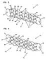
- FIG. 3is a front perspective view of a first embodiment of a bulkhead adapter plate according to the principles of the present disclosure
- FIG. 4is a rear perspective view of the bulkhead adapter plate of FIG. 3 ;
- FIG. 5is a front perspective view of one embodiment of a cable management panel including two bulkhead adapter plates in accordance with the principles disclosed;
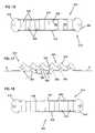
- FIG. 6is a top plan view of a sheet form of the bulkhead adapter plate of FIG. 3 , illustrated prior to a bending process;
- FIG. 7is a bottom view of the bulkhead adapter plate of FIG. 3 formed upon completion of the bending process of the sheet form of FIG. 6 ;
- FIG. 8is a side elevation view of the bulkhead adapter plate of FIG. 3 formed upon completion of the bending process of the sheet form of FIG. 6 ;
- FIG. 9is a top plan view of the bulkhead adapter plate of FIG. 3 formed upon completion of the bending process of the sheet form of FIG. 6 ;
- FIG. 10is another side elevation view of the bulkhead adapter plate of FIG. 3 formed upon completion of the bending process of the sheet form of FIG. 6 ;
- FIG. 11is a top plan view of another sheet form that forms a second embodiment of a bulkhead adapter plate, illustrated prior to a bending process;
- FIG. 12is front perspective view of the second embodiment of the bulkhead adapter plate formed from the sheet form of FIG. 11 in accordance with the principles disclosed, and further showing adapters mounted to the bulkhead adapter plate;
- FIG. 13is a front perspective view of third embodiment of a bulkhead adapter plate according to the principles of the present disclosure.
- FIG. 14is a rear perspective view of the bulkhead adapter plate of FIG. 13 ;
- FIG. 15is a top plan view of a sheet form of the bulkhead adapter plate of FIG. 13 , illustrated prior to a bending process;
- FIG. 16is a bottom view of the bulkhead adapter plate of FIG. 13 formed upon completion of the bending process of the sheet form of FIG. 15 ;
- FIG. 17is a side elevation view of the bulkhead adapter plate of FIG. 13 formed upon completion of the bending process of the sheet form of FIG. 15 ;
- FIG. 18is a top plan view of the bulkhead adapter plate of FIG. 13 formed upon completion of the bending process of the sheet form of FIG. 15 ;
- FIG. 19is a top plan view of another sheet form that forms a fourth embodiment of a bulkhead adapter plate similar to FIG. 13 , illustrated prior to a bending process;
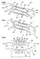
- FIG. 20is a rear perspective view of fifth embodiment of a bulkhead adapter plate according to the principles of the present disclosure.
- FIG. 21is a front perspective view of the bulkhead adapter plate of FIG. 20 ;
- FIG. 22is a top plan view of a sheet form of the bulkhead adapter plate of FIG. 20 , illustrated prior to a bending process;
- FIG. 23is a bottom view of the bulkhead adapter plate of FIG. 20 formed upon completion of the bending process of the sheet form of FIG. 22 ;
- FIG. 24is a side elevation view of the bulkhead adapter plate of FIG. 20 formed upon completion of the bending process of the sheet form of FIG. 22 ;
- FIG. 25is a front perspective view of sixth embodiment of a bulkhead adapter plate according to the principles of the present disclosure.
- FIG. 26is a rear perspective view of the bulkhead adapter plate of FIG. 25 ;
- FIG. 27is a top plan view of a sheet form of the bulkhead adapter plate of FIG. 25 , illustrated prior to a bending process;
- FIG. 28is a bottom view of the bulkhead adapter plate of FIG. 25 formed upon completion of the bending process of the sheet form of FIG. 27 ;
- FIG. 29is a side elevation view of the bulkhead adapter plate of FIG. 25 formed upon completion of the bending process of the sheet form of FIG. 27 ;
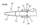
- FIG. 30is a schematic representation of a tool that can be used to remove adapters from the mounting openings of one or more of the disclosed bulkhead adapter plate embodiments.
- FIGS. 1 and 2illustrate a prior art adapter plate 2 used to mount adapters (not shown) to telecommunications equipment.
- the adapter platedefines a plurality of holes 3 sized to receive the adapters.
- a flat sheet of metalis put through a series of bending operations. In particular, a first bending operation is performed to create a first bend 4 , a second bending operation is then performed to create a second bend 5 , a third bending operation is then performed to create a third bend 6 , and so on.
- thirteen bending operationsare performed.
- Each of the thirteen bending operationsis performed sequentially. As can be understood, as the bending operations progress, the previously bent portions can become deformed and fall out of acceptable manufacturing tolerances. In particular, one problem often arising in the manufacture of such plates concerns the flatness of the front face 8 (defined by plane PP). The sequential bending operations cause the front face 8 to bow, twist, and otherwise fall outside an acceptable range of a specified dimensional flatness. Manufacturers commonly have to rework such plate components in an attempt to meet the required dimensional flatness.
- the bulkhead adapter platecan be used in cable management drawers, such as the drawer 12 shown in FIG. 5 .
- the drawer 12includes two bulkhead adapter assemblies 14 that include a bulkhead adapter plate, such as the bulkhead adapter plate 10 shown in FIG. 3 .
- the bulkhead adapter assemblies 14mount within openings of a front panel 16 of the cable management drawer 12 . Further details of an example cable management drawer or panel that can utilize the presently disclosed bulkhead adapter plates are described in U.S. Provisional Application No. 61/072,184, filed Mar. 28, 2008, U.S. Provisional Application No. 61/126,672, filed May 5, 2008, and U.S. Application No. 12,381,160, filed Mar. 6, 2009 which applications are incorporated herein by reference.
- the bulkhead adapter plate 10generally includes a first flange end 18 , a second flange end 20 , and an adapter frame 22 .
- the adapter frame 22extends between the first and second flange ends 18 and 20 .
- a mounting hole 24is formed in each of the first and second flange ends 18 , 20 .
- the mounting holes 24are sized to receive fasteners 26 ( FIG. 5 ) that mount the bulkhead adapter plate 10 to the cable management drawer 12 .
- the bulkhead adapter plate 10 of the present disclosuredefines a plurality of integral adapter mounting openings 30 .
- the adapter mounting openings 30are sized to receive adapters 32 (see e.g., FIG. 12 ), such as SC type adapter or LC type adapters; the openings can be sized to receive other types of adapters as well.
- the adapters and the adapter plate 10define the bulkhead adapter assembly 14 ( FIG. 5 ) that mounts in the front panel 16 of the cable management drawer 12 .
- the adapter frame 22 of the bulkhead adapter plate 10includes a first side portion 34 , a second side portion 36 , and a center portion 38 located between the first and second side portions.
- the center portion 38 of the adapter frame 22is integrally connected to the first and second flange ends 18 , 20 of the bulkhead adapter plate 10 .
- the bulkhead adapter plate 10originates as a flat sheet of metal 40 .
- the flat sheet of metal 40includes each of the first and second flange ends 18 , 20 , the first and second side portions 34 , 36 of the adapter frame 22 , and the center portion 38 of the adapter frame 22 .
- the flat sheet of metal 40further defines first and second apertures 42 , 43 .
- first apertures 42 and six of the second apertures 43are provided.
- Each of the first apertures 42has a first aperture portion 44 that extends into or is formed within the center portion 38 of the adapter frame 22 , and a second aperture portion 46 that extends into or is formed within one of the side portions 34 , 36 of the adapter frame.
- each of the second apertures 43has a first aperture portion 76 that extends into or is formed within the center portion 38 of the adapter frame 22 , and a second aperture portion 78 that extends into or is formed within one of the side portions 34 , 36 of the adapter frame.
- the center portion 38 of the flat sheet of metal 40also includes a first row 50 of center tabs 52 and a second row 54 of center tabs 52 .
- the center tabs 52are initially located within the first aperture portions 76 of the second apertures 43 .
- the center tabs 52further partly define the first aperture portions 44 of the first apertures 42 .
- Each of the center tabs 52 of the first and second rows 50 , 54is interconnected to a cross piece 58 of the center portion 38 .
- each cross piece 58extends between and is interconnected to each of the first and second side portions 34 , 36 of the adapter frame 22 .
- Through holes 48are provided in each of the side portions 34 , 36 and the center tabs 52 of the adapter frame 22 .
- the cross pieces 58 of the adapter frame 22define a plane P ( FIG. 8 ).
- the flatness of plane Pis often specified as a manufacturing constraint because the flatness can affect the proper fit between the adapters 32 and the adapter mounting openings 30 of the adapter plate 10 , and can also affect the proper fit between the adapter plate 10 and the opening in the front panel 16 of the cable management drawer 12 .
- the present flat sheet of metal 40 and forming processproduces a bulkhead adapter plate having a significantly improved flatness.
- the present flat sheet of metal 40 and the forming processfurther reduces the cost of manufacturing by reducing the number of bending operations; and likewise reduces costs by reducing rework associated with conventional manufacturing operations.
- the flat sheet of metal 40undergoes four bending procedures.
- one row of the first and second rows 50 , 54 of center tabs 52(e.g., row 50 ) is first bent generally perpendicular to plane P ( FIG. 8 ) at a bend line B 1 .
- the other of the first and second rows (e.g., 54 ) of tabs 52is then similarly bent generally perpendicular to the plane P at the bend line B 1 .
- one of the first and second side portions (e.g., 34 ) of the flat sheet of metal 40is bent generally perpendicular to plane P at a bend line (e.g., B 2 ); and last, the other of the first and second side portions (e.g., 36 ) is bent generally perpendicular to plane P at a bend line (e.g., B 3 ).
- Each of the bending operationsincludes bending the portions 34 , 36 and the tabs 52 at bend lines B 1 -B 3 that extend along a major dimension (i.e., the length L, FIG. 6 ) of the adapter frame 22 .
- the bending operations of the prior art methodincluding bending the sheet of metal at bend lines (e.g., 4 , 5 of FIG. 1 ) that extend along a transverse minor dimension (i.e., the width) of the adapter plate 2 . Only four bending operations are required to produce the bulkhead adapter plate of FIGS. 3 and 4 , as opposed to the thirteen bending operations required to produce the prior art plate 2 of FIG. 1 .
- first and second side portions 34 , 36are generally parallel to one another.
- the first and second rows of tabs 52 of the flat sheet of metal 40now define a single row of tabs 52 that are generally parallel to the first and second side portions 34 , 36 .
- the apertures 42 , 43 of the flat sheet of metal 40form the adapter mounting openings 30 of the bulkhead adapter plate 10 .
- the first portions 44 and 76 ( FIG. 6 ) of the first and second apertures 42 , 43form opening faces 62 (see FIGS. 7 and 8 ) in plane P to the adapter mounting openings 30 .
- the second portions 46 and 78 ( FIG. 6 ) of the first and second apertures 42 , 43form angled side openings 64 (see FIGS. 8 and 10 ) of the adapter mounting openings 30 .
- the angled side openings 64are formed in each of the first and second side portions 34 , 36 of the bulkhead adapter plate 10 .
- the angled side openings 64are defined by first and second perpendicular edges 80 , 82 .
- Each of edges 80 , 82extends at non-perpendicular angle A 1 , A 2 ( FIG. 8 ) relative to plane P.
- the angled side openings 64 of the mounting openings 30receive the adapters 32 in an angled orientation (see e.g., FIG. 12 ) relative to the center portion 38 (i.e., plane P) of the adapter frame 22 .
- an array of twelve angled adapter mounting openings 30 including two rows of six aligned openingsis formed.
- other numbers of openingscan be formed in accordance with the principles disclosed.
- the angled mounting openings 30 of the bulkhead adapter plate 10are provided in part by the location of the apertures 42 , 43 in the flat sheet of metal 40 .
- the apertures 42 , 43are located such that the bend lines B 2 and B 3 intersect the apertures 42 , 43 .
- the intersection of the apertures 42 , 43define the first aperture portions 44 , 76 that are formed in the center portion 38 and the second aperture portion 46 , 78 that are formed in the side portions 34 , 36 .
- each of the first and second side portions 34 , 36has notched cutouts 66 formed in an edge 68 opposite the respective bend line B 2 , B 3 .
- the notched cutoutspermit a technician to install or insert the adapters into the mounting openings 30 from either a front side 74 ( FIG. 3 ) of the bulkhead adapter plate 10 or a rear side 75 ( FIG. 4 ) of the bulkhead adapter plate.
- the adapters 32are oriented at an angle relative to the plane P ( FIG. 8 ) defined by the center portion 38 of the bulkhead adapter plate 10 .
- the adapters 32are then inserted within the mounting openings 30 .
- a first locating shoulder 70 of the adapter 32contacts the first edge 80 of the mounting opening 30 .
- a second locating shoulder 72 of the adaptercontacts an edge 84 of the center tab 52 . The contact between the locating shoulders 70 , 72 and the edges limits the axial insertion of the adapters 32 .
- mounting tabs 60located on opposite sides of the adapters 32 engage the through holes 48 ( FIG. 3 ) of the bulkhead adapter plate 10 .
- one mounting tab 60 of a single adapter 32engages one of the through hole 48 in one of the side portions 34 , 36
- the other mounting tab 60engages the through hole 48 in one of the center tabs 52 .
- the first locating shoulder 70 of the adapter 32contacts an edge 86 of the cutout 66 (see also FIG. 8 ) of the respective side portion (e.g., 36 ).
- the second locating shoulder 72 of the adaptercontacts a bottom edge 88 (see also FIG. 6 ) of the center tab 52 .
- the mounting tabs 60located on the opposite sides of the adapters 32 engage the through holes 48 ( FIG. 4 ) of the bulkhead adapter plate 10 .
- FIG. 11another sheet of metal 240 used in the manufacture of a second embodiment of a bulkhead adapter plate 210 ( FIG. 12 ) is illustrated.
- the resulting bulkhead adapter plate 210includes first and second flange ends 218 , 220 and an adapter frame 222 located between the ends.
- the adapter frame 222includes a first side portion 234 , a second side portion 236 , and a center portion 238 located between the side portions.
- the center portion 238 of the flat sheet of metal 240includes a first row 250 of center tabs 252 and a second row 254 of center tabs 252 .
- Each of the center tabs 252is interconnected to a cross piece 258 of the center portion 238 .
- the cross pieces 258 to which the center tabs 252 are integrally attachedare connected to only one of the side portions 234 , 236 , rather than to both side portions.
- This embodimentpermits the bulkhead adapter plate 210 to have a shortened overall length in comparison to the first embodiment; for use in applications requiring the particular shortened length.
- the bulkhead adapter plate 310generally includes a first flange end 318 , a second flange end 320 , and an adapter frame 322 .
- the adapter frame 322extends between the first and second flange ends 318 and 320 .
- a mounting hole 324is formed in each of the first and second flange ends 318 , 320 .
- the mounting holes 324are sized to receive fasteners 26 ( FIG. 5 ) that mount the bulkhead adapter plate 310 to a cable management drawer (e.g., 12 in FIG. 5 ).
- the bulkhead adapter plate 310defines a plurality of integral adapter mounting openings 330 .
- the adapter mounting openings 330are sized to receive adapters such as SC type adapter or LC type adapters.
- the openingsreceive adapters each having two connection locations; the openings can be sized to receive other types of adapters as well.
- the adapters and the adapter plate 310define a bulkhead adapter assembly (see for example, 14 in FIG. 5 ) that mounts in the front panel (e.g., 16 ) of a cable management drawer.
- the adapter frame 322 of the bulkhead adapter plate 310includes a first side portion 334 , a second side portion 336 , and a center portion 338 located between the first and second side portions.
- the center portion 338 of the adapter frame 322is integrally connected to the first and second flange ends 318 , 320 of the bulkhead adapter plate 310 .
- the bulkhead adapter plate 310originates as a flat sheet of metal 340 .
- the flat sheet of metal 340includes each of the first and second flange ends 318 , 320 , the first and second side portion 334 , 336 of the adapter frame 322 , and the center portion 338 of the adapter frame 322 .
- the flat sheet of metal 340further defines apertures 342 .
- six apertures 342are provided.
- Each of the apertures 342has a first aperture portion 344 that is formed within the center portion 338 of the adapter frame 322 , a second aperture portion 346 that extends into or is formed within the side portion 334 of the adapter frame, and a third aperture portion 347 that extends into or is formed within the side portion 336 of the adapter frame.
- Cross pieces 358 of the center portion 338generally define first aperture portions 344 of the apertures 342 .
- the cross pieces 358extend between and are interconnected to each of the first and second side portions 334 , 336 of the adapter frame 322 .
- the cross pieces 358 of the adapter frame 322define a plane P ( FIG. 17 , see also FIG. 13 ).
- Through holes 348are provided in each of the side portions 334 , 336 of the adapter frame 322 .
- the flat sheet of metal 340undergoes two bending procedures.
- one of the first and second side portions (e.g., 334 ) of the flat sheet of metal 340is bent generally perpendicular to plane P at a bend line (e.g., B 1 ).
- the other of the first and second side portions (e.g., 336 )is then bent generally perpendicular to plane P at a bend line (e.g., B 2 ).
- Each of the bending operationsincludes bending the portions 334 , 336 at bend lines B 1 -B 2 that extend along a major dimension (i.e., the length L, FIG.
- the first and second side portions 334 , 336are generally parallel to one another.
- the apertures 342 of the flat sheet of metal 340form the adapter mounting openings 330 of the bulkhead adapter plate 310 .
- the first portions 344 ( FIG. 16 , see also FIG. 15 ) of the apertures 342form opening faces 362 (see FIGS. 16 and 17 ) in plane P to the adapter mounting openings 330 .
- the second and third portions 346 and 347 of the apertures 342form angled side openings 364 (see FIGS. 14 and 17 ) of the adapter mounting openings 330 .
- the angled side openings 364are formed in each of the first and second side portions 334 , 336 of the bulkhead adapter plate 310 .
- the angled side openings 364are defined by first and second perpendicular edges 380 , 382 . Each of edges 380 , 382 extends at non-perpendicular angle A 1 , A 2 ( FIG. 17 ) relative to plane P.
- the angled side openings 364 of the mounting openings 330receive the adapters in an angled orientation relative to the center portion 338 (i.e., plane P) of the adapter frame 322 .
- an array of six angled adapter mounting openings 330is formed. As can be understood, other numbers of openings can be formed in accordance with the principles disclosed.
- the angled mounting openings 330 of the bulkhead adapter plate 310are provided in part by the location of the apertures 342 in the flat sheet of metal 340 .
- the apertures 342are located such that the bend lines B 1 and B 2 intersect the apertures 342 .
- the intersection of the apertures 342define the first aperture portions 344 that are formed in the center portion 338 and the second and third aperture portion 346 , 347 that are formed in the side portions 334 , 336 .
- each of the first and second side portion 334 , 336has notched cutouts 366 formed in an edge 368 opposite the respective bend line B 1 , B 2 .
- the notched cutoutspermit a technician to install or insert adapters into the mounting openings 330 from either a front side 374 ( FIG. 13 ) of the bulkhead adapter plate 310 or a rear side 375 ( FIG. 14 ) of the bulkhead adapter plate.
- adaptersare inserted within the mounting openings 330 .
- a first locating shoulder of the adaptercontacts the first edge 380 of the opening side 346 in the first side portion 334 .
- a second locating shoulder of the adaptercontacts the first edge 380 of the opening side 346 in the second side portion 336 .
- the contact between the locating shoulders and the edges 380limits the axial insertion of the adapters.
- mounting tabs located on opposite sides of the adaptersengage the through holes 348 ( FIG. 13 ) of the bulkhead adapter plate 310 .
- one mounting tab of a single adapterengages one of the through hole 348 in the first side portion 334
- the other mounting tabengages the corresponding through hole 348 in the second side portion 336 .
- the first locating shoulder of the adaptercontacts each edge 386 of two corresponding cutouts 366 (see also FIG. 15 ) of the side portions 334 , 336 .
- the mounting tabs of the adaptersengage the through holes 348 ( FIG. 14 ) of the bulkhead adapter plate 310 .
- FIG. 19another sheet of metal 440 used in the manufacture of a fourth embodiment of a bulkhead adapter plate (similar to bulkhead adapter plate 310 in FIG. 13 ) is illustrated.
- the sheet of metal 440 , and resulting bulkhead adapter plateinclude first and second flange ends 418 , 420 and an adapter frame 422 located between the ends.
- the adapter frame 422includes a first side portion 434 , a second side portion 436 , and a center portion 438 located between the side portions.
- the center portion 438 of the flat sheet of metal 440includes cross pieces 458 that generally define the first portion first aperture portions 444 of apertures 442 .
- the cross pieces 458are narrower provide a shortened overall length in comparison to the previous embodiment; for use in applications requiring the particular shortened length.
- the bulkhead adapter plate 510includes a first flange end 518 , a second flange end 520 , and an adapter frame 522 .
- the adapter frame 522extends between the first and second flange ends 518 and 520 .
- a mounting hole 524is formed in each of the first and second flange ends 518 , 520 .
- the mounting holes 524are sized to receive fasteners 26 ( FIG. 5 ) that mount the bulkhead adapter plate 510 to a cable management drawer (e.g., 12 in FIG. 5 ).
- the bulkhead adapter plate 510defines first and second integral adapter mounting openings 530 , 531 .
- the adapter mounting openings 530 , 531each sized to receive an aligned number of adapters, such as SC type adapter or LC type adapters.
- the adapters and the adapter plate 510define the bulkhead adapter assembly (see for example, 14 in FIG. 5 ) that mounts in the front panel (e.g., 16 ) of the cable management drawer.
- the adapter frame 522 of the bulkhead adapter plate 510includes a first side portion 534 , a second side portion 536 , and a center portion 538 located between the first and second side portions.
- Each of the first and second side portions 534 , 536 , and the center portion 538 of the adapter frame 522is integrally connected to the first and second flange ends 518 , 520 of the bulkhead adapter plate 510 .
- the bulkhead adapter plate 510originates as a flat sheet of metal 540 .
- the flat sheet of metal 540includes each of the first and second flange ends 518 , 520 , the first and second side portion 534 , 536 of the adapter frame 522 , and the center portion 538 of the adapter frame 522 .
- Each of the first and second side portions 534 , 536 and the center portion 538 of the adapter frame 522has front cutouts 565 and rear cutouts 566 .
- Through holes 548are provided in each of the side portions 534 , 536 and the center portion 538 of the adapter frame 522 .
- the adapter frame 522has a front 574 that generally defines a plane P ( FIG. 24 ).
- the flat sheet of metal 540( FIG. 22 ) undergoes three bending procedures.
- the center portion 538is first bent generally perpendicular to plane P ( FIG. 24 ) at a bend line B 1 .
- One of the first and second side portion(e.g., 536 ) is then bent generally perpendicular to the plane P at a bend line (e.g., B 2 ).
- the other of the first and second side portions(e.g., 534 ) is bent generally perpendicular to plane P at a bend line (e.g., B 3 ).
- Each of the bending operationsincludes bending the portions 534 , 536 , 538 at bend lines B 1 -B 3 that extend along a major dimension (i.e., the length L, FIG. 22 ) of the adapter frame 522 .
- Only three bending operationsare required to produce the bulkhead adapter plate of FIGS. 20 and 21 , as opposed to the thirteen bending operations required to produce the prior art plate 2 of FIG. 1 .
- the first and second side portions 534 , 536 , and the center portion 538 of the adapter frame 522are generally parallel to one another.
- the front cutouts 565 of the flat sheet of metal 540form angled side openings 564 of the adapter mounting openings 530 , 531 .
- the angled side openings 564are defined by first and second perpendicular edges 580 , 582 . Each of edges 580 , 582 extends at non-perpendicular angle A 1 , A 2 ( FIG. 24 ) relative to plane P.
- the angled side openings 564 of the mounting openings 530receive the adapters in an angled orientation relative to the plane P of the adapter frame 522 .
- the rear cutouts 566 of the flat sheet of metal 540form angled side openings 567 ( FIG. 24 ).
- the angled side openings 567are defined by first and second perpendicular edges 581 , 583 . Each of edges 581 , 583 extends at non-perpendicular angle relative to plane P.
- an array of twelve angled adapterscan be mounted within the two mounting openings 530 , 531 , the array including two rows of six aligned and angled adapters.
- other numbers of adapters or array configurationscan be formed in accordance with the principles disclosed.
- adaptersTo assemble a bulkhead adapter assembly, adapters inserted within the mounting openings 530 , 531 . Referring to FIG. 21 , when inserted from the front side 574 of the bulkhead adapter plate 510 , a first locating shoulder of the adapter contacts the first edge 580 of the one of the side portions (e.g., 534 ). Likewise, a second locating shoulder of the adapter contacts the first edge 580 of the center portion 538 . The contact between the locating shoulders and the edges limits the axial insertion of the adapters.
- mounting tabs located on opposite sides of the adaptersengage the through holes 548 ( FIG. 21 ) of the bulkhead adapter plate 510 .
- one mounting tab of a single adapterengages one of the through hole 548 in one of the side portions (e.g., 534 ), and the other mounting tab engages the through hole 548 in the center portion 538 .
- the first locating shoulder of the adaptercontacts the edge 581 of the rear cutout 566 (see also FIG. 22 ) of one of the side portions (e.g., 536 ).
- the second locating shoulder of the adaptercontacts the edge 581 of the rear cutout 566 of the center portion 538 .
- the mounting tabs located on the opposite sides of the adaptersengage the through holes 548 ( FIG. 20 ) of the bulkhead adapter plate 510 .
- the bulkhead adapter plate 610includes a first flange end 618 , a second flange end 620 , and an adapter frame 622 .
- the adapter frame 622extends between the first and second flange ends 618 and 620 .
- a mounting hole 624is formed in each of the first and second flange ends 618 , 620 .
- the mounting holes 624are sized to receive fasteners 26 ( FIG. 5 ) that mount the bulkhead adapter plate 610 to a cable management drawer (e.g., 12 in FIG. 5 ).
- the bulkhead adapter plate 610defines first and second integral adapter mounting openings 630 , 631 .
- the adapter mounting openings 630 , 631each sized to receive an aligned number of adapters, such as SC type adapter or LC type adapters.
- the adapters and the adapter plate 610define the bulkhead adapter assembly (see for example, 14 in FIG. 5 ) that mounts in the front panel (e.g., 16 ) of the cable management drawer.
- the adapter frame 622 of the bulkhead adapter plate 610includes a first side portion 634 , a second side portion 636 , a first center portion 638 , and a second center portion 639 .
- Each of the side portions 634 , 636 , and the center portions 638 , 639 of the adapter frame 622is integrally connected to the first and second flange ends 618 , 620 of the bulkhead adapter plate 610 .
- the bulkhead adapter plate 610originates as a flat sheet of metal 640 . Similar to the previous embodiment, each of the side portions 634 , 636 and the center portions 638 , 639 of the adapter frame 622 has front cutouts 665 and rear cutouts 661 . Through holes 648 are provided in each of the side portions 634 , 636 and the center portions 638 , 639 of the adapter frame 622 .
- the adapter frame 622has a front 674 that generally defines a plane P ( FIG. 29 ).
- the flat sheet of metal 640( FIG. 27 ) undergoes four bending procedures.
- one of the first and second center portions(e.g., 638 ) is first bent generally perpendicular to plane P ( FIG. 29 ) at a bend line B 1 .
- the other of the first and second center portions(e.g., 639 ) is then bent generally perpendicular to plane P at a bend line (e.g., B 2 ).
- first and second side portione.g., 636
- first and second side portionse.g., 634
- bend linee.g., B 4
- Each of the bending operationsincludes bending the portions 634 , 636 , 638 , and 639 at bend lines B 1 -B 4 that extend along a major dimension (i.e., the length L, FIG. 27 ) of the adapter frame 622 . Only four bending operations are required to produce the bulkhead adapter plate of FIGS. 25 and 26 . Referring to FIG. 28 , upon completion of the four bending operations, the first and second side portions 634 , 636 and the first and second center portions 638 , 639 of the adapter frame 622 are generally parallel to one another.
- the front cutouts 665 of the flat sheet of metal 640form angled side openings 664 of the adapter mounting openings 630 , 631 .
- the angled side openings 664are defined by first and second perpendicular edges 680 , 682 . Each of edges 680 , 682 extends at non-perpendicular angle A 1 , A 2 ( FIG. 29 ) relative to plane P.
- the angled side openings 664 of the mounting openings 630receive the adapters in an angled orientation relative to the plane P of the adapter frame 622 .
- the rear cutouts 661 of the flat sheet of metal 640form angled side openings 667 ( FIG. 29 ).
- the angled side openings 667are defined by first and second perpendicular edges 681 , 683 . Each of edges 681 , 683 extends at non-perpendicular angle relative to plane P.
- an array of twelve angled adapterscan be mounted within the two mounting openings 630 , 631 , the array including two rows of six aligned and angled adapters.
- other numbers of adapters or array configurationscan be formed in accordance with the principles disclosed.
- adaptersTo assemble a bulkhead adapter assembly, adapters inserted within the mounting openings 630 , 631 . Referring to FIG. 25 , when inserted from the front side 674 of the bulkhead adapter plate 610 , a first locating shoulder of the adapter contacts the first edge 680 of the one of the side portions (e.g., 634 ). Likewise, a second locating shoulder of the adapter contacts the first edge 680 of a corresponding one of the center portions (e.g., 638 ). The contact between the locating shoulders and the edges limits the axial insertion of the adapters.
- mounting tabs located on opposite sides of the adaptersengage the through holes 648 ( FIG. 25 ) of the bulkhead adapter plate 610 .
- one mounting tab of a single adapterengages one of the through hole 648 in one of the side portions (e.g., 634 ), and the other mounting tab engages the through hole 648 in the corresponding one of the center portions (e.g., 638 ).
- the first locating shoulder of the adaptercontacts the edge 681 of the rear cutout 661 (see also FIG. 27 ) of one of the side portions (e.g., 636 ).
- the second locating shoulder of the adaptercontacts the edge 681 of the rear cutout 661 of the corresponding one of the center portions (e.g., 639 ).
- the mounting tabs located on the opposite sides of the adaptersengage the through holes 648 ( FIG. 26 ) of the bulkhead adapter plate 610 .
- the tool 700can be used to remove an adapter from the mounting openings of the various bulkhead adapter panels presently disclosed.
- the tool 700generally includes a body 710 having thin arms 720 .
- the thin arms 720are inserted between adapter 32 and the portions of the adapter frame (e.g., side portion 234 and center tab 252 in FIG. 12 ) that are retaining the adapter.
- the armscontact the flexible mounting tabs 60 .
- the contactcauses the flexible mounting tabs 60 to flex toward one another and disengage from the through holes 248 .
- the adapter 32can then be removed from the mounting opening.
Landscapes
- Physics & Mathematics (AREA)
- General Physics & Mathematics (AREA)
- Optics & Photonics (AREA)
- Installation Of Indoor Wiring (AREA)
- Bridges Or Land Bridges (AREA)
- Diaphragms For Electromechanical Transducers (AREA)
- Adornments (AREA)
- Threshing Machine Elements (AREA)
Abstract
Description
Claims (8)
Priority Applications (11)
| Application Number | Priority Date | Filing Date | Title |
|---|---|---|---|
| US12/381,162US7978951B2 (en) | 2008-03-28 | 2009-03-06 | Bulkhead with angled openings and method |
| PCT/US2009/037243WO2009120523A1 (en) | 2008-03-28 | 2009-03-16 | Adapter plate with angled openings and method of manufacture |
| AT09724891TATE528675T1 (en) | 2008-03-28 | 2009-03-16 | ADAPTER PLATE WITH ANGLED OPENINGS AND PRODUCTION METHOD THEREOF |
| AU2009228859AAU2009228859A1 (en) | 2008-03-28 | 2009-03-16 | Adapter plate with angled openings and method of manufacture |
| EP09724891AEP2257842B1 (en) | 2008-03-28 | 2009-03-16 | Adapter plate with angled openings and method of manufacture |
| MX2010010470AMX2010010470A (en) | 2008-03-28 | 2009-03-16 | Adapter plate with angled openings and method of manufacture. |
| BRPI0909714ABRPI0909714A2 (en) | 2008-03-28 | 2009-03-16 | adapter plate with angled openings and production process |
| CN2009801114435ACN101981481A (en) | 2008-03-28 | 2009-03-16 | Adapter plate with angled opening and method of making same |
| CA2716107ACA2716107A1 (en) | 2008-03-28 | 2009-03-16 | Adapter plate with angled openings and method of manufacture |
| ZA2010/07631AZA201007631B (en) | 2008-03-28 | 2010-10-26 | Adapter plate with angled openings and method of manufacture |
| US13/158,153US8494330B2 (en) | 2008-03-28 | 2011-06-10 | Bulkhead with angled openings and method |
Applications Claiming Priority (2)
| Application Number | Priority Date | Filing Date | Title |
|---|---|---|---|
| US7218608P | 2008-03-28 | 2008-03-28 | |
| US12/381,162US7978951B2 (en) | 2008-03-28 | 2009-03-06 | Bulkhead with angled openings and method |
Related Child Applications (1)
| Application Number | Title | Priority Date | Filing Date |
|---|---|---|---|
| US13/158,153DivisionUS8494330B2 (en) | 2008-03-28 | 2011-06-10 | Bulkhead with angled openings and method |
Publications (2)
| Publication Number | Publication Date |
|---|---|
| US20090274431A1 US20090274431A1 (en) | 2009-11-05 |
| US7978951B2true US7978951B2 (en) | 2011-07-12 |
Family
ID=40740016
Family Applications (2)
| Application Number | Title | Priority Date | Filing Date |
|---|---|---|---|
| US12/381,162Active2029-11-19US7978951B2 (en) | 2008-03-28 | 2009-03-06 | Bulkhead with angled openings and method |
| US13/158,153Expired - Fee RelatedUS8494330B2 (en) | 2008-03-28 | 2011-06-10 | Bulkhead with angled openings and method |
Family Applications After (1)
| Application Number | Title | Priority Date | Filing Date |
|---|---|---|---|
| US13/158,153Expired - Fee RelatedUS8494330B2 (en) | 2008-03-28 | 2011-06-10 | Bulkhead with angled openings and method |
Country Status (10)
| Country | Link |
|---|---|
| US (2) | US7978951B2 (en) |
| EP (1) | EP2257842B1 (en) |
| CN (1) | CN101981481A (en) |
| AT (1) | ATE528675T1 (en) |
| AU (1) | AU2009228859A1 (en) |
| BR (1) | BRPI0909714A2 (en) |
| CA (1) | CA2716107A1 (en) |
| MX (1) | MX2010010470A (en) |
| WO (1) | WO2009120523A1 (en) |
| ZA (1) | ZA201007631B (en) |
Cited By (3)
| Publication number | Priority date | Publication date | Assignee | Title |
|---|---|---|---|---|
| US20110142409A1 (en)* | 2009-12-15 | 2011-06-16 | Askey Computer Corp. | Optical fiber adapter fixing element |
| US20140370226A1 (en)* | 2013-06-17 | 2014-12-18 | Cisco Technology, Inc. | Panel assembly |
| US9435975B2 (en) | 2013-03-15 | 2016-09-06 | Commscope Technologies Llc | Modular high density telecommunications frame and chassis system |
Families Citing this family (46)
| Publication number | Priority date | Publication date | Assignee | Title |
|---|---|---|---|---|
| US7876993B2 (en)* | 2008-05-05 | 2011-01-25 | Adc Telecommunications, Inc. | Drawer arrangement with rack and pinion |
| DE102010000551A1 (en)* | 2010-02-25 | 2011-08-25 | Unimet GmbH, 87669 | Punching and bending process |
| US8600208B2 (en) | 2010-08-24 | 2013-12-03 | Adc Telecommunications, Inc. | Fiber optic telecommunications module |
| DE102012010391B4 (en)* | 2011-06-17 | 2025-08-21 | Phoenix Contact Gmbh & Co. Kg | Electrical connection module |
| US9417418B2 (en) | 2011-09-12 | 2016-08-16 | Commscope Technologies Llc | Flexible lensed optical interconnect device for signal distribution |
| US9002166B2 (en) | 2011-10-07 | 2015-04-07 | Adc Telecommunications, Inc. | Slidable fiber optic connection module with cable slack management |
| RU2611105C2 (en) | 2011-10-07 | 2017-02-21 | Адс Телекоммьюникейшнз, Инк. | Fibre-optic cartridge, system and method |
| US9170391B2 (en) | 2011-10-07 | 2015-10-27 | Adc Telecommunications, Inc. | Slidable fiber optic connection module with cable slack management |
| CN103975264B (en) | 2011-10-07 | 2015-09-16 | Adc电信公司 | Slidable fiber optic connection module with cable slack management |
| US9075203B2 (en) | 2012-01-17 | 2015-07-07 | Adc Telecommunications, Inc. | Fiber optic adapter block |
| US9195021B2 (en) | 2012-09-21 | 2015-11-24 | Adc Telecommunications, Inc. | Slidable fiber optic connection module with cable slack management |
| US10082636B2 (en) | 2012-09-21 | 2018-09-25 | Commscope Technologies Llc | Slidable fiber optic connection module with cable slack management |
| US9146374B2 (en) | 2012-09-28 | 2015-09-29 | Adc Telecommunications, Inc. | Rapid deployment packaging for optical fiber |
| NZ706687A (en) | 2012-09-28 | 2017-09-29 | Adc Telecommunications Inc | Fiber optic cassette |
| US9223094B2 (en) | 2012-10-05 | 2015-12-29 | Tyco Electronics Nederland Bv | Flexible optical circuit, cassettes, and methods |
| FR3001046B1 (en)* | 2013-01-11 | 2016-03-25 | Nexans | DEVICE FOR DISASSEMBLING A CONNECTION IN AN OPTICAL CONNECTION MODULE |
| CN105074525A (en) | 2013-01-29 | 2015-11-18 | 泰科电子瑞侃有限公司 | Fiber Distribution System |
| US9128262B2 (en) | 2013-02-05 | 2015-09-08 | Adc Telecommunications, Inc. | Slidable telecommunications tray with cable slack management |
| US9052489B2 (en) | 2013-02-08 | 2015-06-09 | All Systems Broadband, Inc. | Fiber shelf break-out plate |
| US20140247541A1 (en)* | 2013-02-26 | 2014-09-04 | Realm Communications Group, Inc. | Telecom cabinet dual tray slider |
| WO2014133943A1 (en) | 2013-02-27 | 2014-09-04 | Adc Telecommunications, Inc. | Slidable fiber optic connection module with cable slack management |
| AP2015008820A0 (en) | 2013-04-24 | 2015-10-31 | Adc Czech Republic Sro | Optical fiber distribution system |
| EP2989496B1 (en) | 2013-04-24 | 2019-06-12 | CommScope Connectivity Belgium BVBA | Universal mounting mechanism for mounting a telecommunications chassis to a telecommunications fixture |
| US20150093089A1 (en)* | 2013-10-02 | 2015-04-02 | Opterna Technology Limited | Swing Out Optical Fiber Tray |
| WO2016094331A1 (en) | 2014-12-10 | 2016-06-16 | Commscope Technologies Llc | Fiber optic cable slack management module |
| AU2016239875C1 (en) | 2015-04-03 | 2021-06-24 | CommScope Connectivity Belgium BVBA | Telecommunications distribution elements |
| ES2851948T3 (en) | 2016-04-19 | 2021-09-09 | Commscope Inc North Carolina | Telecom rack with slide out trays |
| WO2017184501A1 (en) | 2016-04-19 | 2017-10-26 | Commscope, Inc. Of North Carolina | Door assembly for a telecommunications chassis with a combination hinge structure |
| JP6878125B2 (en)* | 2017-04-27 | 2021-05-26 | 三和電気工業株式会社 | Patch panel |
| WO2018226959A1 (en) | 2017-06-07 | 2018-12-13 | Commscope Technologies Llc | Fiber optic adapter and cassette |
| US11409068B2 (en) | 2017-10-02 | 2022-08-09 | Commscope Technologies Llc | Fiber optic circuit and preparation method |
| US11385429B2 (en) | 2017-10-18 | 2022-07-12 | Commscope Technologies Llc | Fiber optic connection cassette |
| US11852882B2 (en) | 2018-02-28 | 2023-12-26 | Commscope Technologies Llc | Packaging assembly for telecommunications equipment |
| WO2019204317A1 (en) | 2018-04-16 | 2019-10-24 | Commscope Technologies Llc | Adapter structure |
| US11635578B2 (en) | 2018-04-17 | 2023-04-25 | CommScope Connectivity Belgium BVBA | Telecommunications distribution elements |
| WO2020043914A1 (en) | 2018-08-31 | 2020-03-05 | CommScope Connectivity Belgium BVBA | Frame assemblies for optical fiber distribution elements |
| PL3844973T3 (en) | 2018-08-31 | 2025-03-03 | CommScope Connectivity Belgium BVBA | Frame assemblies for optical fiber distribution elements |
| EP3844546A1 (en) | 2018-08-31 | 2021-07-07 | CommScope Connectivity Belgium BVBA | Frame assemblies for optical fiber distribution elements |
| EP3845044B1 (en) | 2018-08-31 | 2023-02-15 | CommScope Connectivity Belgium BVBA | Frame assemblies for optical fiber distribution elements |
| EP3844547A1 (en) | 2018-08-31 | 2021-07-07 | CommScope Connectivity Belgium BVBA | Frame assemblies for optical fiber distribution elements |
| WO2020084012A1 (en) | 2018-10-23 | 2020-04-30 | CommScope Connectivity Belgium BVBA | Frame assemblies for optical fiber distribution elements |
| EP3914947A1 (en) | 2019-01-25 | 2021-12-01 | CommScope Connectivity Belgium BVBA | Frame assemblies for optical fiber distribution elements |
| US11467359B2 (en) | 2019-11-07 | 2022-10-11 | Opternaam, Inc. | Carriage for patching, splitting, and/or guiding fiber optic cables |
| WO2021148544A1 (en) | 2020-01-22 | 2021-07-29 | CommScope Connectivity Belgium BVBA | Cable termination units for optical fiber distribution elements |
| US12099246B2 (en) | 2020-01-24 | 2024-09-24 | CommScope Connectivity Belgium BVBA | Telecommunications distribution elements |
| US12339511B2 (en) | 2020-03-31 | 2025-06-24 | Commscope Technologies Llc | Fiber optic cable management systems and methods |
Citations (21)
| Publication number | Priority date | Publication date | Assignee | Title |
|---|---|---|---|---|
| US5011257A (en) | 1988-06-29 | 1991-04-30 | British Telecommunications Public Limited Company | Optical fiber patch panel |
| US5214735A (en) | 1992-04-06 | 1993-05-25 | Adc Telecommunications, Inc. | Fiber optic connector retainer |
| US5289558A (en) | 1991-10-05 | 1994-02-22 | Krone Aktiengesellshaft | Switching assembly for glass fiber cables of the telecommunication and data technology |
| US5363465A (en) | 1993-02-19 | 1994-11-08 | Adc Telecommunications, Inc. | Fiber optic connector module |
| WO2000028363A1 (en) | 1998-11-07 | 2000-05-18 | Tyco Electronics Raychem Nv | A panel for supporting a plurality of fibre optic connectors |
| US6208796B1 (en) | 1998-07-21 | 2001-03-27 | Adc Telecommunications, Inc. | Fiber optic module |
| USRE37489E1 (en) | 1989-07-31 | 2002-01-01 | Adc Telecommunications, Inc. | Optical fiber distribution frame |
| EP1186921A2 (en) | 2000-09-06 | 2002-03-13 | Hirose Electric Co., Ltd. | Optical cable adapter or connector |
| US6435727B1 (en) | 1999-02-05 | 2002-08-20 | Fiber Connections, Inc. | Connector for fiber optic cable |
| US20020150372A1 (en) | 2001-02-12 | 2002-10-17 | Fiber Optic Network Solutions Corp. | Optical fiber enclosure system |
| EP1298470A2 (en) | 2001-09-17 | 2003-04-02 | Hirose Electric Co., Ltd. | Optical connector system |
| US20030095772A1 (en) | 2001-11-16 | 2003-05-22 | Solheid James J. | Fiber termination block with angled slide |
| US6678457B2 (en)* | 2001-12-01 | 2004-01-13 | Unicom Technologies, Co., Ltd | Optical splitter module |
| US6760531B1 (en) | 1999-03-01 | 2004-07-06 | Adc Telecommunications, Inc. | Optical fiber distribution frame with outside plant enclosure |
| EP1473578A2 (en) | 2003-05-02 | 2004-11-03 | Panduit Corporation | Fiber optic connector removal tool |
| US20050135769A1 (en) | 2003-08-28 | 2005-06-23 | Makooi Babak B. | Optical connector |
| US6920274B2 (en) | 2003-12-23 | 2005-07-19 | Adc Telecommunications, Inc. | High density optical fiber distribution frame with modules |
| US20050207719A1 (en) | 2004-03-17 | 2005-09-22 | Yazaki Corporation | Optical connector insertion/extraction tool |
| US7241182B2 (en) | 2001-11-16 | 2007-07-10 | Adc Telecommunications, Inc. | Angled RJ to RJ patch panel |
| US7376321B2 (en) | 2004-08-09 | 2008-05-20 | Adc Telecommunications, Inc. | Modules including multiple rows of adapters for high density optical fiber distribution frame |
| US7496269B1 (en)* | 2007-04-12 | 2009-02-24 | Adc Gmbh | Fiber optic enclosure |
Family Cites Families (1)
| Publication number | Priority date | Publication date | Assignee | Title |
|---|---|---|---|---|
| US7764859B2 (en) | 2008-03-28 | 2010-07-27 | Adc Telecommunications, Inc. | Universal cable management panel |
- 2009
- 2009-03-06USUS12/381,162patent/US7978951B2/enactiveActive
- 2009-03-16CACA2716107Apatent/CA2716107A1/ennot_activeAbandoned
- 2009-03-16MXMX2010010470Apatent/MX2010010470A/enunknown
- 2009-03-16AUAU2009228859Apatent/AU2009228859A1/ennot_activeAbandoned
- 2009-03-16CNCN2009801114435Apatent/CN101981481A/enactivePending
- 2009-03-16BRBRPI0909714Apatent/BRPI0909714A2/ennot_activeIP Right Cessation
- 2009-03-16ATAT09724891Tpatent/ATE528675T1/ennot_activeIP Right Cessation
- 2009-03-16EPEP09724891Apatent/EP2257842B1/ennot_activeNot-in-force
- 2009-03-16WOPCT/US2009/037243patent/WO2009120523A1/enactiveApplication Filing
- 2010
- 2010-10-26ZAZA2010/07631Apatent/ZA201007631B/enunknown
- 2011
- 2011-06-10USUS13/158,153patent/US8494330B2/ennot_activeExpired - Fee Related
Patent Citations (22)
| Publication number | Priority date | Publication date | Assignee | Title |
|---|---|---|---|---|
| US5011257A (en) | 1988-06-29 | 1991-04-30 | British Telecommunications Public Limited Company | Optical fiber patch panel |
| USRE37489E1 (en) | 1989-07-31 | 2002-01-01 | Adc Telecommunications, Inc. | Optical fiber distribution frame |
| US5289558A (en) | 1991-10-05 | 1994-02-22 | Krone Aktiengesellshaft | Switching assembly for glass fiber cables of the telecommunication and data technology |
| US5214735A (en) | 1992-04-06 | 1993-05-25 | Adc Telecommunications, Inc. | Fiber optic connector retainer |
| US5363465A (en) | 1993-02-19 | 1994-11-08 | Adc Telecommunications, Inc. | Fiber optic connector module |
| US6208796B1 (en) | 1998-07-21 | 2001-03-27 | Adc Telecommunications, Inc. | Fiber optic module |
| WO2000028363A1 (en) | 1998-11-07 | 2000-05-18 | Tyco Electronics Raychem Nv | A panel for supporting a plurality of fibre optic connectors |
| US6435727B1 (en) | 1999-02-05 | 2002-08-20 | Fiber Connections, Inc. | Connector for fiber optic cable |
| US6760531B1 (en) | 1999-03-01 | 2004-07-06 | Adc Telecommunications, Inc. | Optical fiber distribution frame with outside plant enclosure |
| US6741783B2 (en)* | 2000-09-06 | 2004-05-25 | Hirose Electric Co., Ltd. | Optical cable adapter or connector |
| EP1186921A2 (en) | 2000-09-06 | 2002-03-13 | Hirose Electric Co., Ltd. | Optical cable adapter or connector |
| US20020150372A1 (en) | 2001-02-12 | 2002-10-17 | Fiber Optic Network Solutions Corp. | Optical fiber enclosure system |
| EP1298470A2 (en) | 2001-09-17 | 2003-04-02 | Hirose Electric Co., Ltd. | Optical connector system |
| US20030095772A1 (en) | 2001-11-16 | 2003-05-22 | Solheid James J. | Fiber termination block with angled slide |
| US7241182B2 (en) | 2001-11-16 | 2007-07-10 | Adc Telecommunications, Inc. | Angled RJ to RJ patch panel |
| US6678457B2 (en)* | 2001-12-01 | 2004-01-13 | Unicom Technologies, Co., Ltd | Optical splitter module |
| EP1473578A2 (en) | 2003-05-02 | 2004-11-03 | Panduit Corporation | Fiber optic connector removal tool |
| US20050135769A1 (en) | 2003-08-28 | 2005-06-23 | Makooi Babak B. | Optical connector |
| US6920274B2 (en) | 2003-12-23 | 2005-07-19 | Adc Telecommunications, Inc. | High density optical fiber distribution frame with modules |
| US20050207719A1 (en) | 2004-03-17 | 2005-09-22 | Yazaki Corporation | Optical connector insertion/extraction tool |
| US7376321B2 (en) | 2004-08-09 | 2008-05-20 | Adc Telecommunications, Inc. | Modules including multiple rows of adapters for high density optical fiber distribution frame |
| US7496269B1 (en)* | 2007-04-12 | 2009-02-24 | Adc Gmbh | Fiber optic enclosure |
Non-Patent Citations (7)
| Title |
|---|
| Adapter Plate drawing; dated Dec. 21, 2007; 1 page. |
| Component drawings of Mini Fiber Module, including Chassis Top, Support, and Bottom Cover; dated Nov. 28, 2007; 3 pages. |
| Invitation to Pay Additional Fees with Partial International Search mailed Jul. 7, 2009. |
| Mini Fiber Module Assembly (assembly drawing of the components dated Nov. 28, 2007); Admitted prior art; 1 page. |
| U.S. Appl. No. 12/381,160, filed Mar. 6, 2009; Krampotich et al. |
| U.S. Appl. No. 61/072,184, filed Mar. 28, 2008; Krampotich; 29 pages. |
| U.S. Appl. No. 61/126,672, filed May 5, 2008; Krampotich; 33 pages. |
Cited By (6)
| Publication number | Priority date | Publication date | Assignee | Title |
|---|---|---|---|---|
| US20110142409A1 (en)* | 2009-12-15 | 2011-06-16 | Askey Computer Corp. | Optical fiber adapter fixing element |
| US9435975B2 (en) | 2013-03-15 | 2016-09-06 | Commscope Technologies Llc | Modular high density telecommunications frame and chassis system |
| US9952398B2 (en) | 2013-03-15 | 2018-04-24 | Commscope Technologies Llc | Modular high density telecommunications frame and chassis system |
| US10473875B2 (en) | 2013-03-15 | 2019-11-12 | Commscope Technologies Llc | Modular high density telecommunications frame and chassis system |
| US20140370226A1 (en)* | 2013-06-17 | 2014-12-18 | Cisco Technology, Inc. | Panel assembly |
| US9247319B2 (en)* | 2013-06-17 | 2016-01-26 | Cisco Technology, Inc. | Panel assembly |
Also Published As
| Publication number | Publication date |
|---|---|
| BRPI0909714A2 (en) | 2019-09-24 |
| AU2009228859A2 (en) | 2011-08-04 |
| US20110255836A1 (en) | 2011-10-20 |
| EP2257842A1 (en) | 2010-12-08 |
| EP2257842B1 (en) | 2011-10-12 |
| CA2716107A1 (en) | 2009-10-01 |
| WO2009120523A1 (en) | 2009-10-01 |
| US8494330B2 (en) | 2013-07-23 |
| ATE528675T1 (en) | 2011-10-15 |
| US20090274431A1 (en) | 2009-11-05 |
| MX2010010470A (en) | 2010-10-20 |
| ZA201007631B (en) | 2011-08-31 |
| CN101981481A (en) | 2011-02-23 |
| AU2009228859A1 (en) | 2009-10-01 |
Similar Documents
| Publication | Publication Date | Title |
|---|---|---|
| US7978951B2 (en) | Bulkhead with angled openings and method | |
| US9291778B2 (en) | Multi-port adapter block | |
| US7359610B2 (en) | Cable manager including nestable radius limiter | |
| US6504986B1 (en) | Optical fiber assembly | |
| JP5113850B2 (en) | Termination cassette release latch | |
| US5363465A (en) | Fiber optic connector module | |
| US8428418B2 (en) | Fiber optic adapter plate and cassette | |
| US7493002B2 (en) | Fiber optic adapter cassette and panel | |
| US6974348B2 (en) | High-density multi-port-module patch panel system | |
| US8221169B2 (en) | Fanning module, fanning strip, and cable management panel | |
| US20140185992A1 (en) | Fiber optic module housing and fiber optic module | |
| US11395436B2 (en) | Modular telecommunications patch panel system | |
| US20250254448A1 (en) | Shielded keystone patch panel with snap-in face plate | |
| US8213759B1 (en) | System for retaining optical devices |
Legal Events
| Date | Code | Title | Description |
|---|---|---|---|
| AS | Assignment | Owner name:ADC TELECOMMUNICATIONS, INC., MINNESOTA Free format text:ASSIGNMENT OF ASSIGNORS INTEREST;ASSIGNORS:KRAMPOTICH, DENNIS;SZCZODROSKI, ANTHONY;REEL/FRAME:022753/0447;SIGNING DATES FROM 20090325 TO 20090521 Owner name:ADC TELECOMMUNICATIONS, INC., MINNESOTA Free format text:ASSIGNMENT OF ASSIGNORS INTEREST;ASSIGNORS:KRAMPOTICH, DENNIS;SZCZODROSKI, ANTHONY;SIGNING DATES FROM 20090325 TO 20090521;REEL/FRAME:022753/0447 | |
| STCF | Information on status: patent grant | Free format text:PATENTED CASE | |
| FPAY | Fee payment | Year of fee payment:4 | |
| AS | Assignment | Owner name:TYCO ELECTRONICS SERVICES GMBH, SWITZERLAND Free format text:ASSIGNMENT OF ASSIGNORS INTEREST;ASSIGNOR:ADC TELECOMMUNICATIONS, INC.;REEL/FRAME:036060/0174 Effective date:20110930 | |
| AS | Assignment | Owner name:COMMSCOPE EMEA LIMITED, IRELAND Free format text:ASSIGNMENT OF ASSIGNORS INTEREST;ASSIGNOR:TYCO ELECTRONICS SERVICES GMBH;REEL/FRAME:036956/0001 Effective date:20150828 | |
| AS | Assignment | Owner name:COMMSCOPE TECHNOLOGIES LLC, NORTH CAROLINA Free format text:ASSIGNMENT OF ASSIGNORS INTEREST;ASSIGNOR:COMMSCOPE EMEA LIMITED;REEL/FRAME:037012/0001 Effective date:20150828 | |
| AS | Assignment | Owner name:JPMORGAN CHASE BANK, N.A., AS COLLATERAL AGENT, ILLINOIS Free format text:PATENT SECURITY AGREEMENT (TERM);ASSIGNOR:COMMSCOPE TECHNOLOGIES LLC;REEL/FRAME:037513/0709 Effective date:20151220 Owner name:JPMORGAN CHASE BANK, N.A., AS COLLATERAL AGENT, ILLINOIS Free format text:PATENT SECURITY AGREEMENT (ABL);ASSIGNOR:COMMSCOPE TECHNOLOGIES LLC;REEL/FRAME:037514/0196 Effective date:20151220 Owner name:JPMORGAN CHASE BANK, N.A., AS COLLATERAL AGENT, IL Free format text:PATENT SECURITY AGREEMENT (ABL);ASSIGNOR:COMMSCOPE TECHNOLOGIES LLC;REEL/FRAME:037514/0196 Effective date:20151220 Owner name:JPMORGAN CHASE BANK, N.A., AS COLLATERAL AGENT, IL Free format text:PATENT SECURITY AGREEMENT (TERM);ASSIGNOR:COMMSCOPE TECHNOLOGIES LLC;REEL/FRAME:037513/0709 Effective date:20151220 | |
| MAFP | Maintenance fee payment | Free format text:PAYMENT OF MAINTENANCE FEE, 8TH YEAR, LARGE ENTITY (ORIGINAL EVENT CODE: M1552); ENTITY STATUS OF PATENT OWNER: LARGE ENTITY Year of fee payment:8 | |
| AS | Assignment | Owner name:ANDREW LLC, NORTH CAROLINA Free format text:RELEASE BY SECURED PARTY;ASSIGNOR:JPMORGAN CHASE BANK, N.A.;REEL/FRAME:048840/0001 Effective date:20190404 Owner name:REDWOOD SYSTEMS, INC., NORTH CAROLINA Free format text:RELEASE BY SECURED PARTY;ASSIGNOR:JPMORGAN CHASE BANK, N.A.;REEL/FRAME:048840/0001 Effective date:20190404 Owner name:ALLEN TELECOM LLC, ILLINOIS Free format text:RELEASE BY SECURED PARTY;ASSIGNOR:JPMORGAN CHASE BANK, N.A.;REEL/FRAME:048840/0001 Effective date:20190404 Owner name:COMMSCOPE, INC. OF NORTH CAROLINA, NORTH CAROLINA Free format text:RELEASE BY SECURED PARTY;ASSIGNOR:JPMORGAN CHASE BANK, N.A.;REEL/FRAME:048840/0001 Effective date:20190404 Owner name:COMMSCOPE TECHNOLOGIES LLC, NORTH CAROLINA Free format text:RELEASE BY SECURED PARTY;ASSIGNOR:JPMORGAN CHASE BANK, N.A.;REEL/FRAME:048840/0001 Effective date:20190404 Owner name:COMMSCOPE, INC. OF NORTH CAROLINA, NORTH CAROLINA Free format text:RELEASE BY SECURED PARTY;ASSIGNOR:JPMORGAN CHASE BANK, N.A.;REEL/FRAME:049260/0001 Effective date:20190404 Owner name:COMMSCOPE TECHNOLOGIES LLC, NORTH CAROLINA Free format text:RELEASE BY SECURED PARTY;ASSIGNOR:JPMORGAN CHASE BANK, N.A.;REEL/FRAME:049260/0001 Effective date:20190404 Owner name:ANDREW LLC, NORTH CAROLINA Free format text:RELEASE BY SECURED PARTY;ASSIGNOR:JPMORGAN CHASE BANK, N.A.;REEL/FRAME:049260/0001 Effective date:20190404 Owner name:REDWOOD SYSTEMS, INC., NORTH CAROLINA Free format text:RELEASE BY SECURED PARTY;ASSIGNOR:JPMORGAN CHASE BANK, N.A.;REEL/FRAME:049260/0001 Effective date:20190404 Owner name:ALLEN TELECOM LLC, ILLINOIS Free format text:RELEASE BY SECURED PARTY;ASSIGNOR:JPMORGAN CHASE BANK, N.A.;REEL/FRAME:049260/0001 Effective date:20190404 | |
| AS | Assignment | Owner name:JPMORGAN CHASE BANK, N.A., NEW YORK Free format text:TERM LOAN SECURITY AGREEMENT;ASSIGNORS:COMMSCOPE, INC. OF NORTH CAROLINA;COMMSCOPE TECHNOLOGIES LLC;ARRIS ENTERPRISES LLC;AND OTHERS;REEL/FRAME:049905/0504 Effective date:20190404 Owner name:WILMINGTON TRUST, NATIONAL ASSOCIATION, AS COLLATE Free format text:PATENT SECURITY AGREEMENT;ASSIGNOR:COMMSCOPE TECHNOLOGIES LLC;REEL/FRAME:049892/0051 Effective date:20190404 Owner name:JPMORGAN CHASE BANK, N.A., NEW YORK Free format text:ABL SECURITY AGREEMENT;ASSIGNORS:COMMSCOPE, INC. OF NORTH CAROLINA;COMMSCOPE TECHNOLOGIES LLC;ARRIS ENTERPRISES LLC;AND OTHERS;REEL/FRAME:049892/0396 Effective date:20190404 Owner name:WILMINGTON TRUST, NATIONAL ASSOCIATION, AS COLLATERAL AGENT, CONNECTICUT Free format text:PATENT SECURITY AGREEMENT;ASSIGNOR:COMMSCOPE TECHNOLOGIES LLC;REEL/FRAME:049892/0051 Effective date:20190404 | |
| AS | Assignment | Owner name:WILMINGTON TRUST, DELAWARE Free format text:SECURITY INTEREST;ASSIGNORS:ARRIS SOLUTIONS, INC.;ARRIS ENTERPRISES LLC;COMMSCOPE TECHNOLOGIES LLC;AND OTHERS;REEL/FRAME:060752/0001 Effective date:20211115 | |
| AS | Assignment | Owner name:COMMSCOPE, INC. OF NORTH CAROLINA, NORTH CAROLINA Free format text:PARTIAL RELEASE OF ABL SECURITY INTEREST;ASSIGNOR:JPMORGAN CHASE BANK, N.A.;REEL/FRAME:060649/0305 Effective date:20220712 Owner name:ARRIS ENTERPRISES LLC, NORTH CAROLINA Free format text:PARTIAL RELEASE OF ABL SECURITY INTEREST;ASSIGNOR:JPMORGAN CHASE BANK, N.A.;REEL/FRAME:060649/0305 Effective date:20220712 Owner name:COMMSCOPE TECHNOLOGIES LLC, NORTH CAROLINA Free format text:PARTIAL RELEASE OF ABL SECURITY INTEREST;ASSIGNOR:JPMORGAN CHASE BANK, N.A.;REEL/FRAME:060649/0305 Effective date:20220712 Owner name:COMMSCOPE, INC. OF NORTH CAROLINA, NORTH CAROLINA Free format text:PARTIAL RELEASE OF TERM LOAN SECURITY INTEREST;ASSIGNOR:JPMORGAN CHASE BANK, N.A.;REEL/FRAME:060649/0286 Effective date:20220712 Owner name:ARRIS ENTERPRISES LLC, NORTH CAROLINA Free format text:PARTIAL RELEASE OF TERM LOAN SECURITY INTEREST;ASSIGNOR:JPMORGAN CHASE BANK, N.A.;REEL/FRAME:060649/0286 Effective date:20220712 Owner name:COMMSCOPE TECHNOLOGIES LLC, NORTH CAROLINA Free format text:PARTIAL RELEASE OF TERM LOAN SECURITY INTEREST;ASSIGNOR:JPMORGAN CHASE BANK, N.A.;REEL/FRAME:060649/0286 Effective date:20220712 Owner name:BISON PATENT LICENSING, LLC, GEORGIA Free format text:ASSIGNMENT OF ASSIGNORS INTEREST;ASSIGNOR:COMMSCOPE TECHNOLOGIES LLC;REEL/FRAME:060641/0312 Effective date:20220628 | |
| AS | Assignment | Owner name:COMMSCOPE, INC. OF NORTH CAROLINA, NORTH CAROLINA Free format text:PARTIAL TERMINATION AND RELEASE OF SECURITY INTEREST IN PATENTS;ASSIGNOR:WILMINGTON TRUST, NATIONAL ASSOCIATION, AS COLLATERAL AGENT;REEL/FRAME:060671/0324 Effective date:20220711 Owner name:ARRIS ENTERPRISES LLC, PENNSYLVANIA Free format text:PARTIAL TERMINATION AND RELEASE OF SECURITY INTEREST IN PATENTS;ASSIGNOR:WILMINGTON TRUST, NATIONAL ASSOCIATION, AS COLLATERAL AGENT;REEL/FRAME:060671/0324 Effective date:20220711 Owner name:COMMSCOPE TECHNOLOGIES LLC, NORTH CAROLINA Free format text:PARTIAL TERMINATION AND RELEASE OF SECURITY INTEREST IN PATENTS;ASSIGNOR:WILMINGTON TRUST, NATIONAL ASSOCIATION, AS COLLATERAL AGENT;REEL/FRAME:060671/0324 Effective date:20220711 | |
| MAFP | Maintenance fee payment | Free format text:PAYMENT OF MAINTENANCE FEE, 12TH YEAR, LARGE ENTITY (ORIGINAL EVENT CODE: M1553); ENTITY STATUS OF PATENT OWNER: LARGE ENTITY Year of fee payment:12 | |
| AS | Assignment | Owner name:ARRIS ENTERPRISES LLC, GEORGIA Free format text:RELEASE BY SECURED PARTY;ASSIGNOR:WILMINGTON TRUST, NATIONAL ASSOCIATION;REEL/FRAME:063270/0220 Effective date:20221116 Owner name:COMMSCOPE, INC. OF NORTH CAROLINA, NORTH CAROLINA Free format text:RELEASE BY SECURED PARTY;ASSIGNOR:WILMINGTON TRUST, NATIONAL ASSOCIATION;REEL/FRAME:063270/0220 Effective date:20221116 Owner name:COMMSCOPE TECHNOLOGIES LLC, NORTH CAROLINA Free format text:RELEASE BY SECURED PARTY;ASSIGNOR:WILMINGTON TRUST, NATIONAL ASSOCIATION;REEL/FRAME:063270/0220 Effective date:20221116 | |
| AS | Assignment | Owner name:ARRIS ENTERPRISES LLC, GEORGIA Free format text:PARTIAL TERMINATION AND RELEASE OF SECURITY INTEREST IN PATENTS RECORDED AT R/F 060752/0001;ASSIGNOR:WILMINGTON TRUST;REEL/FRAME:063322/0209 Effective date:20221116 Owner name:COMMSCOPE, INC. OF NORTH CAROLINA, NORTH CAROLINA Free format text:PARTIAL TERMINATION AND RELEASE OF SECURITY INTEREST IN PATENTS RECORDED AT R/F 060752/0001;ASSIGNOR:WILMINGTON TRUST;REEL/FRAME:063322/0209 Effective date:20221116 Owner name:COMMSCOPE TECHNOLOGIES LLC, NORTH CAROLINA Free format text:PARTIAL TERMINATION AND RELEASE OF SECURITY INTEREST IN PATENTS RECORDED AT R/F 060752/0001;ASSIGNOR:WILMINGTON TRUST;REEL/FRAME:063322/0209 Effective date:20221116 | |
| AS | Assignment | Owner name:RUCKUS WIRELESS, LLC (F/K/A RUCKUS WIRELESS, INC.), NORTH CAROLINA Free format text:RELEASE OF SECURITY INTEREST AT REEL/FRAME 049905/0504;ASSIGNOR:JPMORGAN CHASE BANK, N.A., AS COLLATERAL AGENT;REEL/FRAME:071477/0255 Effective date:20241217 Owner name:COMMSCOPE TECHNOLOGIES LLC, NORTH CAROLINA Free format text:RELEASE OF SECURITY INTEREST AT REEL/FRAME 049905/0504;ASSIGNOR:JPMORGAN CHASE BANK, N.A., AS COLLATERAL AGENT;REEL/FRAME:071477/0255 Effective date:20241217 Owner name:COMMSCOPE, INC. OF NORTH CAROLINA, NORTH CAROLINA Free format text:RELEASE OF SECURITY INTEREST AT REEL/FRAME 049905/0504;ASSIGNOR:JPMORGAN CHASE BANK, N.A., AS COLLATERAL AGENT;REEL/FRAME:071477/0255 Effective date:20241217 Owner name:ARRIS SOLUTIONS, INC., NORTH CAROLINA Free format text:RELEASE OF SECURITY INTEREST AT REEL/FRAME 049905/0504;ASSIGNOR:JPMORGAN CHASE BANK, N.A., AS COLLATERAL AGENT;REEL/FRAME:071477/0255 Effective date:20241217 Owner name:ARRIS TECHNOLOGY, INC., NORTH CAROLINA Free format text:RELEASE OF SECURITY INTEREST AT REEL/FRAME 049905/0504;ASSIGNOR:JPMORGAN CHASE BANK, N.A., AS COLLATERAL AGENT;REEL/FRAME:071477/0255 Effective date:20241217 Owner name:ARRIS ENTERPRISES LLC (F/K/A ARRIS ENTERPRISES, INC.), NORTH CAROLINA Free format text:RELEASE OF SECURITY INTEREST AT REEL/FRAME 049905/0504;ASSIGNOR:JPMORGAN CHASE BANK, N.A., AS COLLATERAL AGENT;REEL/FRAME:071477/0255 Effective date:20241217 |