US7978883B2 - Device for positioning a user by displaying the user's mirror image, a corresponding positioning method and image-capture apparatus - Google Patents
Device for positioning a user by displaying the user's mirror image, a corresponding positioning method and image-capture apparatusDownload PDFInfo
- Publication number
- US7978883B2 US7978883B2US11/579,420US57942005AUS7978883B2US 7978883 B2US7978883 B2US 7978883B2US 57942005 AUS57942005 AUS 57942005AUS 7978883 B2US7978883 B2US 7978883B2
- Authority
- US
- United States
- Prior art keywords
- user
- images
- positioning
- screen
- image
- Prior art date
- Legal status (The legal status is an assumption and is not a legal conclusion. Google has not performed a legal analysis and makes no representation as to the accuracy of the status listed.)
- Active, expires
Links
Images


Classifications
- G—PHYSICS
- G03—PHOTOGRAPHY; CINEMATOGRAPHY; ANALOGOUS TECHNIQUES USING WAVES OTHER THAN OPTICAL WAVES; ELECTROGRAPHY; HOLOGRAPHY
- G03B—APPARATUS OR ARRANGEMENTS FOR TAKING PHOTOGRAPHS OR FOR PROJECTING OR VIEWING THEM; APPARATUS OR ARRANGEMENTS EMPLOYING ANALOGOUS TECHNIQUES USING WAVES OTHER THAN OPTICAL WAVES; ACCESSORIES THEREFOR
- G03B13/00—Viewfinders; Focusing aids for cameras; Means for focusing for cameras; Autofocus systems for cameras
- G03B13/02—Viewfinders
- G03B13/10—Viewfinders adjusting viewfinders field
- G—PHYSICS
- G06—COMPUTING OR CALCULATING; COUNTING
- G06V—IMAGE OR VIDEO RECOGNITION OR UNDERSTANDING
- G06V40/00—Recognition of biometric, human-related or animal-related patterns in image or video data
- G06V40/10—Human or animal bodies, e.g. vehicle occupants or pedestrians; Body parts, e.g. hands
- G06V40/18—Eye characteristics, e.g. of the iris
- G—PHYSICS
- G06—COMPUTING OR CALCULATING; COUNTING
- G06V—IMAGE OR VIDEO RECOGNITION OR UNDERSTANDING
- G06V40/00—Recognition of biometric, human-related or animal-related patterns in image or video data
- G06V40/60—Static or dynamic means for assisting the user to position a body part for biometric acquisition
- G06V40/67—Static or dynamic means for assisting the user to position a body part for biometric acquisition by interactive indications to the user
Definitions
- the present inventionrelates to a method and a device for positioning a user by simultaneously displaying the user's mirror image together with positioning reference marks.
- such a positioning devicecan be used for positioning the face of a user in front of an image-capture apparatus usable for identification purposes by face recognition or by recognizing the user's eyes.
- Automatic devices for identifying individuals by means of the iris of the eyecomprise one or two cameras for capturing images of the individual's irises.
- the cameras usedpresent limited depth and width of field which makes it necessary for the individual to be accurately positioned relative to the cameras in order to have images that provide sufficient quality to enable irises to be recognized and the individual to be identified.
- a positioning devicethat detects the position of the user and sends visual signals to the user enabling the user to correct position if it is not appropriate. Nevertheless, those signals can be wrongly interpreted, making it impossible to achieve correct positioning without the intervention of an operator.
- An object of the inventionis to provide means enabling the user to be positioned quickly and accurately.
- the inventionprovides a device for positioning the face of a user relative to an image-capture apparatus, the positioning device comprising a picture-taking device arranged to supply horizontally-reversed images, a display screen for displaying the reversed images and connected to the picture-taking device, and means for superposing on the images displayed on the screen at least one positioning reference mark for the user, the positioning reference mark and the displayed images lying substantially in the same plane.
- the screenacts as a mirror in which the user can see his or her reflection and can correct position by getting into alignment with the positioning reference marks. Since the image of the user and the images of the reference marks all lie in the same plane, there is no problem with parallax, and the user experiences no difficulty with accommodation in order to see the user's own image and the reference mark simultaneously and in focus.
- the device of the inventionis also intuitive in character which enables the user to take up the correct position quickly.
- the superposition meansare arranged to superpose two positioning reference marks on two items of the user's body
- the deviceincludes a member for measuring a distance between the user and the picture-taking device, means for determining on the image of the user at said distance a distance between the two elements of the user's body, and adaptation means for adapting the spacing of the positioning reference marks relative to the images as a function of the determined distance that exists between the elements of the user's body.
- the adaptation meansserve to correct for the morphological variations that exist between individuals in order to achieve positioning that is relatively accurate.
- the adaptation meanscomprise a control member for controlling magnification of the images displayed on the screen.
- the positioning deviceincludes means for detecting any misalignment in the images between the positioning reference mark and the user, and means for amplifying the misalignment on the screen.
- the errors that are detectedmay be user offsets sideways, vertically, or in depth. Amplifying positioning errors makes it easier for the user to correct position.
- the inventionalso provides an apparatus for capturing at least one image of a user's eye, the apparatus including at least one image acquisition camera, the capture apparatus comprising a positioning device presenting any of the above characteristics, the screen of the positioning device being mounted in the capture device in such a manner that when the user looks at the screen, said eye of the user lies substantially on the axis of the acquisition camera.
- the user's vision during positioningis then properly directed for image capture such that the operation of capturing the image can follow on immediately from the positioning operation without any need for the user to look in some other direction.
- the inventionalso provides a method of positioning a user relative to an image capture apparatus, the method comprising the steps of filming images of the user substantially continuously, of horizontally reversing the filmed images, and of presenting the reversed images to the user together with at least one positioning reference mark superposed thereon, the positioning reference mark and the images being presented substantially in the same plane.
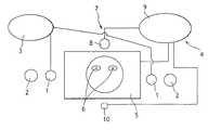
- FIG. 1is a diagrammatic face view of an image-capture apparatus in a first embodiment of the invention
- FIG. 2is a diagrammatic side view of an image-capture apparatus in a second embodiment of the invention.
- FIG. 3is a view analogous to FIG. 2 showing a variant of the second embodiment.
- the inventionis described herein in application to a device for taking images of the eye of a user in order to identify the user.
- the image-capture apparatuscomprises, in a manner that is itself conventional, two cameras 1 for acquiring infrared images of the eyes of the user, and two sources 2 of infrared illumination.
- the cameras 1are disposed on a horizontal line at positions that are spaced apart from each other so that each of them takes images of one of the eyes of a user when the user is in a reference position relative to the cameras. This reference position is a position that enables images of sufficient quality to be obtained of both of the eyes of the user.
- the cameras 1are connected to a computer processor unit 3 , known in itself, that processes the images and identifies the user by recognizing the user's irises.
- the image-capture apparatusincludes a positioning device given overall reference 4 .
- the positioning device 4comprises a screen 5 placed between the two cameras 1 .
- Two positioning reference marks 6are marked on the surface of the screen 5 in positions that are horizontally spaced apart by a distance that corresponds to a standard interocular distance for a user in the reference position and as a function of the nominal magnification of the image.
- the positioning device 4also comprises a picture-taker device generally referenced 7 and comprising a camera 8 that operates in the visible, connected to a control unit 9 that horizontally reverses the images delivered by the camera 8 .
- the camera 8includes a motor-driven zoom lens.
- the control unit 9is arranged to control the motor-driven zoom lens and is connected to the screen 5 .
- the capture apparatusincludes a telemeter 10 connected to the control unit 9 and operating in the infrared.
- the camera 8When a image comes up in front of the image-capture apparatus, the camera 8 continuously takes images of the face of the user. These images are reversed horizontally by the control unit 9 which transmits the reverse images to the screen 5 .
- the screen 5thus appears as a mirror having positioning reference marks 6 marked thereon with which the user is required to align the images of the eyes.
- the images displayed on the screen 5 and the positioning reference marks 6are situated in the same plane such that the images and the reference marks are seen clearly and without parallax.
- using a single camera 8eliminates problems of a dominant eye or master eye which arise with binocular vision.
- the telemeter 10continuously measures the distance between itself and the user. At a predetermined instant, the measured distance and an image of the user at said distance are used by the control unit 9 to determine the interocular distance of the user. If the interocular distance of the user is different from the standard interocular distance, then the zoom lens is controlled to adapt the magnification of the image to the ratio between the user's interocular distance and the standard interocular distance.
- the usercorrects position in order to bring the user's eyes as seen on the screen 5 into alignment with the positioning reference marks 6 .
- the cameras 1capture images of the user's eyes. It should be observed that when the user looks at the screen 5 , the user's eyes are substantially in line with the cameras 1 . Conventional recognition is then performed on the user's irises in order to identify the user.
- the camera 8 of the picture-taking device 7 and the screen 5 of the positioning device 4are no longer disposed in the immediate vicinity of the cameras 1 as in the first embodiment.
- the positioning devicefurther comprises two parallel slate beam-splitters 20 , 21 .
- the beam-splitter 20slopes in front of the cameras 1 and the telemeter 10 which are adjacent.
- the beam-splitter 20is a spectrum separator arranged in conventional manner to transmit infrared radiation and to reflect visible radiation.
- the beam-splitter 20is at 45° relative to the optical axes of the cameras 1 .
- the beam-splitter 21is a flux separator which transmits a fraction of the visible light flux coming from the beam-splitter 20 towards the screen 5 and which reflects a corresponding proportion of the visible light flux towards the camera 8 .
- An accommodation-canceling member 22is placed between the beam-splitters 20 and 21 .
- the accommodation-canceling member 22is constituted in this case by a lens arranged in conventional manner to perform focusing at infinity.
- the beam-splitters 20 and 21 , the accommodation-canceling member 22 , and the screen 5are in alignment substantially on the same axis.
- the positioning device in the second embodimentoperates identically to that of the first embodiment.
- the image visible to the user Uis reflected successively on the beam-splitters 20 and 21 so as to be captured by the camera 8 .
- the screen 5can be seen through the beam-splitter 21 and the accommodation-canceling member 22 , and it is reflected in the beam-splitter 20 towards the user U. Because of the accommodation-canceling member 22 , the user U has no need to accommodate vision in order to see the screen 5 sharply.
- the cameras 1 and the telemeter 10act directly through the beam-splitter 20 .
- the device constituting the second embodimentpresents the advantage that the width of the screen 5 no longer depends on the spacing between the cameras 1 , as is the case for the first embodiment.
- the beam-splitter 21is omitted and the camera 8 is placed in the vicinity of the cameras 1 behind the beam-splitter 20 . Since the beam-splitter 20 transmits radiation that is infrared, the camera 8 used must be sensitive to this radiation.
- the screen 5is disposed directly behind the accommodation-canceling member 22 .
- control unit 9also incorporates a member for detecting misalignment between the positioning reference marks and the eyes of the user and means for amplifying such misalignment that are arranged to enlarge the image and the positioning reference marks in order to amplify the positioning error as the user comes closer to the reference position, thus making positioning easier.
- the amplification meansare also arranged to amplify lateral and/or vertical misalignment by displacing the images displayed on the screen in corresponding manner relative to the positioning reference marks. Wrong positioning in the depth direction, as detected by the telemeter, can also be amplified, e.g. by enlarging the images when the user is too close or by reducing the images when the user is too far away.
- the detection and amplification means in this exampleare computer programs for image processing.
- the positioning device of the inventionis usable for applications other than capturing images of the eyes for identification purposes, and for example it can be used for capturing images of faces for biometric recognition thereof, or more simply in an automatic photograph-taking booth.
- the processor unit 8could be replaced by optical means for horizontally reversing images, such as a lens or a mirror.
- positioning reference marksare shown in the form of crosses in FIG. 1 , other shapes could naturally be used, such as circles.
- the positioning reference markscan also be superposed on the images by an image processing method, such as image overlays or the like, instead of being marked on the screen.
- the spacing between the reference markscan thus be adapted as a function of the interocular distance of the user.
- Adapting the spacing of the positioning reference marks relative to the displayed imagesis optional, and could be omitted, for example when variation in the interocular distance has no harmful influence on positioning.
- the means for detecting misalignment and the amplification meansare usable in all of the embodiments and variants thereof. These means could alternatively be omitted.
- the beam-splittersare described as being in the form of plates, the beam-splitters could be formed using any other means, and in particular using prisms.
- the positions of the screen 5 and the camera 8can be interchanged.
- the positioning deviceneed not have such a member.
- the accommodation-canceling member 22may be disposed somewhere other than between the two semi-reflecting plates 20 , 21 , and in particular between the screen 5 and the semi-reflecting plate 21 .
- the accommodation-canceling member 22is optional and could be omitted, in particular when the light path between the user and the screen is longer than 35 centimeters (cm), a distance beyond which it is assumed that most individuals do not have problems of accommodation.
- the telemeteris also optional.
Landscapes
- Engineering & Computer Science (AREA)
- Physics & Mathematics (AREA)
- General Physics & Mathematics (AREA)
- Human Computer Interaction (AREA)
- Multimedia (AREA)
- Theoretical Computer Science (AREA)
- Health & Medical Sciences (AREA)
- General Health & Medical Sciences (AREA)
- Ophthalmology & Optometry (AREA)
- Image Input (AREA)
- Studio Devices (AREA)
- Cameras Adapted For Combination With Other Photographic Or Optical Apparatuses (AREA)
- Eye Examination Apparatus (AREA)
Abstract
Description
Claims (9)
Applications Claiming Priority (3)
| Application Number | Priority Date | Filing Date | Title |
|---|---|---|---|
| FR0405649AFR2870948B1 (en) | 2004-05-25 | 2004-05-25 | DEVICE FOR POSITIONING A USER BY DISPLAYING ITS MIRROR IMAGE, IMAGE CAPTURE DEVICE AND CORRESPONDING POSITIONING METHOD |
| FR0405649 | 2004-05-25 | ||
| PCT/FR2005/001265WO2006000670A1 (en) | 2004-05-25 | 2005-05-20 | Device for positioning a user by displaying the image thereof in a mirror, and corresponding image capturing device and positioning method |
Publications (2)
| Publication Number | Publication Date |
|---|---|
| US20070159548A1 US20070159548A1 (en) | 2007-07-12 |
| US7978883B2true US7978883B2 (en) | 2011-07-12 |
Family
ID=34945603
Family Applications (1)
| Application Number | Title | Priority Date | Filing Date |
|---|---|---|---|
| US11/579,420Active2028-10-27US7978883B2 (en) | 2004-05-25 | 2005-05-20 | Device for positioning a user by displaying the user's mirror image, a corresponding positioning method and image-capture apparatus |
Country Status (6)
| Country | Link |
|---|---|
| US (1) | US7978883B2 (en) |
| EP (1) | EP1749237B1 (en) |
| JP (1) | JP4829221B2 (en) |
| ES (1) | ES2392555T3 (en) |
| FR (1) | FR2870948B1 (en) |
| WO (1) | WO2006000670A1 (en) |
Cited By (33)
| Publication number | Priority date | Publication date | Assignee | Title |
|---|---|---|---|---|
| US20080122578A1 (en)* | 2006-06-27 | 2008-05-29 | Hoyos Hector T | Ensuring the provenance of passengers at a transportation facility |
| US20090097716A1 (en)* | 2007-10-10 | 2009-04-16 | Lenovo (Beijing) Limited | Camera device and information prompt method |
| US20100232655A1 (en)* | 2007-09-01 | 2010-09-16 | Global Rainmakers, Inc. | System and method for Iris Data Acquisition for Biometric Identification |
| WO2014208052A1 (en)* | 2013-06-26 | 2014-12-31 | Sony Corporation | Image processing apparatus, image processing method, and program |
| US8953849B2 (en) | 2007-04-19 | 2015-02-10 | Eyelock, Inc. | Method and system for biometric recognition |
| US8958606B2 (en) | 2007-09-01 | 2015-02-17 | Eyelock, Inc. | Mirror system and method for acquiring biometric data |
| US9002073B2 (en) | 2007-09-01 | 2015-04-07 | Eyelock, Inc. | Mobile identity platform |
| US9036871B2 (en) | 2007-09-01 | 2015-05-19 | Eyelock, Inc. | Mobility identity platform |
| US9117119B2 (en) | 2007-09-01 | 2015-08-25 | Eyelock, Inc. | Mobile identity platform |
| US9122925B2 (en) | 2011-08-22 | 2015-09-01 | Eyelock, Inc. | Systems and methods for capturing artifact free images |
| US9280706B2 (en) | 2011-02-17 | 2016-03-08 | Eyelock Llc | Efficient method and system for the acquisition of scene imagery and iris imagery using a single sensor |
| US9355299B2 (en) | 2006-10-02 | 2016-05-31 | Eyelock Llc | Fraud resistant biometric financial transaction system and method |
| US9489416B2 (en) | 2006-03-03 | 2016-11-08 | Eyelock Llc | Scalable searching of biometric databases using dynamic selection of data subsets |
| US9495526B2 (en) | 2013-03-15 | 2016-11-15 | Eyelock Llc | Efficient prevention of fraud |
| US9509690B2 (en) | 2015-03-12 | 2016-11-29 | Eyelock Llc | Methods and systems for managing network activity using biometrics |
| US9613281B2 (en) | 2005-11-11 | 2017-04-04 | Eyelock Llc | Methods for performing biometric recognition of a human eye and corroboration of same |
| US9626562B2 (en) | 2006-09-22 | 2017-04-18 | Eyelock, Llc | Compact biometric acquisition system and method |
| US9646217B2 (en) | 2007-04-19 | 2017-05-09 | Eyelock Llc | Method and system for biometric recognition |
| US9716814B2 (en) | 2009-03-30 | 2017-07-25 | Eyelock Llc | Biometric camera mount system |
| US9792497B2 (en) | 2014-09-12 | 2017-10-17 | Eyelock Llc | Methods and apparatus for directing the gaze of a user in an iris recognition system |
| US9965672B2 (en) | 2008-06-26 | 2018-05-08 | Eyelock Llc | Method of reducing visibility of pulsed illumination while acquiring high quality imagery |
| US10032075B2 (en) | 2013-12-23 | 2018-07-24 | Eyelock Llc | Methods and apparatus for power-efficient iris recognition |
| US10043229B2 (en) | 2011-01-26 | 2018-08-07 | Eyelock Llc | Method for confirming the identity of an individual while shielding that individual's personal data |
| US10055733B2 (en) | 2011-04-19 | 2018-08-21 | Eyelock Llc | Biometric chain of provenance |
| DE102017103884A1 (en) | 2017-02-24 | 2018-08-30 | Osram Opto Semiconductors Gmbh | Lighting device, electronic device with a lighting device and use of a lighting device |
| US10074011B2 (en) | 2015-01-20 | 2018-09-11 | Eyelock Llc | Lens system for high quality visible image acquisition and infra-red iris image acquisition |
| US10311300B2 (en) | 2016-05-18 | 2019-06-04 | Eyelock Llc | Iris recognition systems and methods of using a statistical model of an iris for authentication |
| US10311299B2 (en) | 2015-12-21 | 2019-06-04 | Eyelock Llc | Reflected optic camera module for iris recognition in a computing device |
| US10332113B2 (en) | 2014-11-19 | 2019-06-25 | Eyelock Llc | Model-based prediction of an optimal convenience metric for authorizing transactions |
| US10372982B2 (en) | 2014-01-06 | 2019-08-06 | Eyelock Llc | Methods and apparatus for repetitive iris recognition |
| US10534969B2 (en) | 2017-02-24 | 2020-01-14 | Eyelock Llc | Systems and methods for providing illumination for iris biometric acquisition |
| US11068711B2 (en) | 2017-08-31 | 2021-07-20 | Eyelock Llc | Systems and methods of biometric acquisition using positive optical distortion |
| US12175634B2 (en) | 2018-12-19 | 2024-12-24 | Koninklijke Philips N.V. | Mirror assembly |
Families Citing this family (6)
| Publication number | Priority date | Publication date | Assignee | Title |
|---|---|---|---|---|
| US9053323B2 (en)* | 2007-04-13 | 2015-06-09 | Hewlett-Packard Development Company, L.P. | Trusted component update system and method |
| CN101877764B (en)* | 2009-04-29 | 2012-05-30 | 鸿富锦精密工业(深圳)有限公司 | Camera system and method for carrying out assisted composition by utilizing same |
| PT2820476T (en)* | 2012-02-27 | 2017-08-09 | Implicitcare Llc | 360â° imaging system |
| JP2013178702A (en)* | 2012-02-29 | 2013-09-09 | Azbil Corp | Face authentication sensor |
| CN105611153B (en)* | 2015-12-21 | 2019-09-24 | 联想(北京)有限公司 | Image processing method and electronic equipment |
| US10121236B2 (en)* | 2016-10-26 | 2018-11-06 | Himax Technologies Limited | Automatic alignment apparatus and associated method |
Citations (9)
| Publication number | Priority date | Publication date | Assignee | Title |
|---|---|---|---|---|
| US5506632A (en)* | 1993-12-30 | 1996-04-09 | Canon Kabushiki Kaisha | Ophthalmologic apparatus having an electrical magnifier |
| US5664235A (en) | 1992-06-15 | 1997-09-02 | Fuji Photo Film Co., Ltd. | Portrait photography camera and method |
| US5751836A (en)* | 1994-09-02 | 1998-05-12 | David Sarnoff Research Center Inc. | Automated, non-invasive iris recognition system and method |
| DE20101349U1 (en) | 2001-01-25 | 2001-05-03 | WINCOR NIXDORF GmbH & Co. KG, 33106 Paderborn | Self-service terminal with iris or face recognition |
| US6289113B1 (en) | 1998-11-25 | 2001-09-11 | Iridian Technologies, Inc. | Handheld iris imaging apparatus and method |
| US20020130961A1 (en)* | 2001-03-15 | 2002-09-19 | Lg Electronics Inc. | Display device of focal angle and focal distance in iris recognition system |
| US20030012413A1 (en) | 2001-07-16 | 2003-01-16 | Matsushita Electric Industrial Co., Ltd. | Iris identification apparatus and iris image pickup apparatus |
| US20030103030A1 (en) | 2001-12-04 | 2003-06-05 | Desun System Inc. | Two-in-one image display/image capture apparatus and the method thereof and identification system using the same |
| US20040037452A1 (en) | 2000-10-07 | 2004-02-26 | Qritek Co., Ltd., | Iris identification system and method and computer readable storage medium stored therein computer executable instructions to implement iris identification method |
Family Cites Families (3)
| Publication number | Priority date | Publication date | Assignee | Title |
|---|---|---|---|---|
| JP4438214B2 (en)* | 2000-11-02 | 2010-03-24 | 沖電気工業株式会社 | Imaging device |
| JP2002175538A (en)* | 2000-12-08 | 2002-06-21 | Mitsubishi Electric Corp | Portrait generating apparatus, portrait generating method, recording medium recording portrait generating program, communication terminal, and communication method by communication terminal |
| JP2003021859A (en)* | 2001-07-09 | 2003-01-24 | Konica Corp | Guide for photography, figure photographing device and figure printing device |
- 2004
- 2004-05-25FRFR0405649Apatent/FR2870948B1/ennot_activeExpired - Fee Related
- 2005
- 2005-05-20USUS11/579,420patent/US7978883B2/enactiveActive
- 2005-05-20ESES05773072Tpatent/ES2392555T3/ennot_activeExpired - Lifetime
- 2005-05-20EPEP05773072Apatent/EP1749237B1/ennot_activeExpired - Lifetime
- 2005-05-20JPJP2007514000Apatent/JP4829221B2/ennot_activeExpired - Lifetime
- 2005-05-20WOPCT/FR2005/001265patent/WO2006000670A1/ennot_activeApplication Discontinuation
Patent Citations (9)
| Publication number | Priority date | Publication date | Assignee | Title |
|---|---|---|---|---|
| US5664235A (en) | 1992-06-15 | 1997-09-02 | Fuji Photo Film Co., Ltd. | Portrait photography camera and method |
| US5506632A (en)* | 1993-12-30 | 1996-04-09 | Canon Kabushiki Kaisha | Ophthalmologic apparatus having an electrical magnifier |
| US5751836A (en)* | 1994-09-02 | 1998-05-12 | David Sarnoff Research Center Inc. | Automated, non-invasive iris recognition system and method |
| US6289113B1 (en) | 1998-11-25 | 2001-09-11 | Iridian Technologies, Inc. | Handheld iris imaging apparatus and method |
| US20040037452A1 (en) | 2000-10-07 | 2004-02-26 | Qritek Co., Ltd., | Iris identification system and method and computer readable storage medium stored therein computer executable instructions to implement iris identification method |
| DE20101349U1 (en) | 2001-01-25 | 2001-05-03 | WINCOR NIXDORF GmbH & Co. KG, 33106 Paderborn | Self-service terminal with iris or face recognition |
| US20020130961A1 (en)* | 2001-03-15 | 2002-09-19 | Lg Electronics Inc. | Display device of focal angle and focal distance in iris recognition system |
| US20030012413A1 (en) | 2001-07-16 | 2003-01-16 | Matsushita Electric Industrial Co., Ltd. | Iris identification apparatus and iris image pickup apparatus |
| US20030103030A1 (en) | 2001-12-04 | 2003-06-05 | Desun System Inc. | Two-in-one image display/image capture apparatus and the method thereof and identification system using the same |
Cited By (58)
| Publication number | Priority date | Publication date | Assignee | Title |
|---|---|---|---|---|
| US10102427B2 (en) | 2005-11-11 | 2018-10-16 | Eyelock Llc | Methods for performing biometric recognition of a human eye and corroboration of same |
| US9613281B2 (en) | 2005-11-11 | 2017-04-04 | Eyelock Llc | Methods for performing biometric recognition of a human eye and corroboration of same |
| US9792499B2 (en) | 2005-11-11 | 2017-10-17 | Eyelock Llc | Methods for performing biometric recognition of a human eye and corroboration of same |
| US9489416B2 (en) | 2006-03-03 | 2016-11-08 | Eyelock Llc | Scalable searching of biometric databases using dynamic selection of data subsets |
| US20080122578A1 (en)* | 2006-06-27 | 2008-05-29 | Hoyos Hector T | Ensuring the provenance of passengers at a transportation facility |
| US9142070B2 (en) | 2006-06-27 | 2015-09-22 | Eyelock, Inc. | Ensuring the provenance of passengers at a transportation facility |
| US8604901B2 (en) | 2006-06-27 | 2013-12-10 | Eyelock, Inc. | Ensuring the provenance of passengers at a transportation facility |
| US9984290B2 (en) | 2006-09-22 | 2018-05-29 | Eyelock Llc | Compact biometric acquisition system and method |
| US9626562B2 (en) | 2006-09-22 | 2017-04-18 | Eyelock, Llc | Compact biometric acquisition system and method |
| US9355299B2 (en) | 2006-10-02 | 2016-05-31 | Eyelock Llc | Fraud resistant biometric financial transaction system and method |
| US8953849B2 (en) | 2007-04-19 | 2015-02-10 | Eyelock, Inc. | Method and system for biometric recognition |
| US9646217B2 (en) | 2007-04-19 | 2017-05-09 | Eyelock Llc | Method and system for biometric recognition |
| US9959478B2 (en) | 2007-04-19 | 2018-05-01 | Eyelock Llc | Method and system for biometric recognition |
| US10395097B2 (en) | 2007-04-19 | 2019-08-27 | Eyelock Llc | Method and system for biometric recognition |
| US9792498B2 (en) | 2007-09-01 | 2017-10-17 | Eyelock Llc | Mobile identity platform |
| US8553948B2 (en) | 2007-09-01 | 2013-10-08 | Eyelock, Inc. | System and method for iris data acquisition for biometric identification |
| US9192297B2 (en) | 2007-09-01 | 2015-11-24 | Eyelock Llc | System and method for iris data acquisition for biometric identification |
| US10296791B2 (en) | 2007-09-01 | 2019-05-21 | Eyelock Llc | Mobile identity platform |
| US9117119B2 (en) | 2007-09-01 | 2015-08-25 | Eyelock, Inc. | Mobile identity platform |
| US9095287B2 (en) | 2007-09-01 | 2015-08-04 | Eyelock, Inc. | System and method for iris data acquisition for biometric identification |
| US20100232655A1 (en)* | 2007-09-01 | 2010-09-16 | Global Rainmakers, Inc. | System and method for Iris Data Acquisition for Biometric Identification |
| US9946928B2 (en) | 2007-09-01 | 2018-04-17 | Eyelock Llc | System and method for iris data acquisition for biometric identification |
| US8958606B2 (en) | 2007-09-01 | 2015-02-17 | Eyelock, Inc. | Mirror system and method for acquiring biometric data |
| US9055198B2 (en) | 2007-09-01 | 2015-06-09 | Eyelock, Inc. | Mirror system and method for acquiring biometric data |
| US9626563B2 (en) | 2007-09-01 | 2017-04-18 | Eyelock Llc | Mobile identity platform |
| US9036871B2 (en) | 2007-09-01 | 2015-05-19 | Eyelock, Inc. | Mobility identity platform |
| US9633260B2 (en) | 2007-09-01 | 2017-04-25 | Eyelock Llc | System and method for iris data acquisition for biometric identification |
| US9002073B2 (en) | 2007-09-01 | 2015-04-07 | Eyelock, Inc. | Mobile identity platform |
| US20090097716A1 (en)* | 2007-10-10 | 2009-04-16 | Lenovo (Beijing) Limited | Camera device and information prompt method |
| US8842885B2 (en) | 2007-10-10 | 2014-09-23 | Lenovo (Beijing) Limited | Camera device and information prompt method for distance measurement |
| US9965672B2 (en) | 2008-06-26 | 2018-05-08 | Eyelock Llc | Method of reducing visibility of pulsed illumination while acquiring high quality imagery |
| US9716814B2 (en) | 2009-03-30 | 2017-07-25 | Eyelock Llc | Biometric camera mount system |
| US10043229B2 (en) | 2011-01-26 | 2018-08-07 | Eyelock Llc | Method for confirming the identity of an individual while shielding that individual's personal data |
| US9280706B2 (en) | 2011-02-17 | 2016-03-08 | Eyelock Llc | Efficient method and system for the acquisition of scene imagery and iris imagery using a single sensor |
| US10116888B2 (en) | 2011-02-17 | 2018-10-30 | Eyelock Llc | Efficient method and system for the acquisition of scene imagery and iris imagery using a single sensor |
| US10055733B2 (en) | 2011-04-19 | 2018-08-21 | Eyelock Llc | Biometric chain of provenance |
| US9122925B2 (en) | 2011-08-22 | 2015-09-01 | Eyelock, Inc. | Systems and methods for capturing artifact free images |
| US9495526B2 (en) | 2013-03-15 | 2016-11-15 | Eyelock Llc | Efficient prevention of fraud |
| US10332118B2 (en) | 2013-03-15 | 2019-06-25 | Eyelock Llc | Efficient prevention of fraud |
| US9569778B2 (en) | 2013-03-15 | 2017-02-14 | Eyelock, Llc | Efficient prevention of fraud |
| WO2014208052A1 (en)* | 2013-06-26 | 2014-12-31 | Sony Corporation | Image processing apparatus, image processing method, and program |
| US10956733B2 (en) | 2013-06-26 | 2021-03-23 | Sony Corporation | Image processing apparatus and image processing method |
| US10956736B2 (en) | 2013-12-23 | 2021-03-23 | Eyelock Llc | Methods and apparatus for power-efficient iris recognition |
| US10032075B2 (en) | 2013-12-23 | 2018-07-24 | Eyelock Llc | Methods and apparatus for power-efficient iris recognition |
| US10372982B2 (en) | 2014-01-06 | 2019-08-06 | Eyelock Llc | Methods and apparatus for repetitive iris recognition |
| US9792497B2 (en) | 2014-09-12 | 2017-10-17 | Eyelock Llc | Methods and apparatus for directing the gaze of a user in an iris recognition system |
| US10332113B2 (en) | 2014-11-19 | 2019-06-25 | Eyelock Llc | Model-based prediction of an optimal convenience metric for authorizing transactions |
| US10074011B2 (en) | 2015-01-20 | 2018-09-11 | Eyelock Llc | Lens system for high quality visible image acquisition and infra-red iris image acquisition |
| US10997411B2 (en) | 2015-01-20 | 2021-05-04 | Eyelock Llc | Lens system for high quality visible image acquisition and infra-red iris image acquisition |
| US9509690B2 (en) | 2015-03-12 | 2016-11-29 | Eyelock Llc | Methods and systems for managing network activity using biometrics |
| US10009178B2 (en) | 2015-03-12 | 2018-06-26 | Eyelock Llc | Methods and systems for managing network activity using biometrics |
| US10311299B2 (en) | 2015-12-21 | 2019-06-04 | Eyelock Llc | Reflected optic camera module for iris recognition in a computing device |
| US10311300B2 (en) | 2016-05-18 | 2019-06-04 | Eyelock Llc | Iris recognition systems and methods of using a statistical model of an iris for authentication |
| DE102017103884A1 (en) | 2017-02-24 | 2018-08-30 | Osram Opto Semiconductors Gmbh | Lighting device, electronic device with a lighting device and use of a lighting device |
| US10534969B2 (en) | 2017-02-24 | 2020-01-14 | Eyelock Llc | Systems and methods for providing illumination for iris biometric acquisition |
| US11288502B2 (en) | 2017-02-24 | 2022-03-29 | Osram Oled Gmbh | Illumination system, electronic device comprising an illumination system and use of an illumination system |
| US11068711B2 (en) | 2017-08-31 | 2021-07-20 | Eyelock Llc | Systems and methods of biometric acquisition using positive optical distortion |
| US12175634B2 (en) | 2018-12-19 | 2024-12-24 | Koninklijke Philips N.V. | Mirror assembly |
Also Published As
| Publication number | Publication date |
|---|---|
| ES2392555T3 (en) | 2012-12-11 |
| EP1749237B1 (en) | 2012-10-03 |
| JP2008500571A (en) | 2008-01-10 |
| WO2006000670A1 (en) | 2006-01-05 |
| US20070159548A1 (en) | 2007-07-12 |
| FR2870948B1 (en) | 2006-09-01 |
| EP1749237A1 (en) | 2007-02-07 |
| FR2870948A1 (en) | 2005-12-02 |
| JP4829221B2 (en) | 2011-12-07 |
Similar Documents
| Publication | Publication Date | Title |
|---|---|---|
| US7978883B2 (en) | Device for positioning a user by displaying the user's mirror image, a corresponding positioning method and image-capture apparatus | |
| US10869024B2 (en) | Augmented reality displays with active alignment and corresponding methods | |
| US7271839B2 (en) | Display device of focal angle and focal distance in iris recognition system | |
| US8433103B2 (en) | Long distance multimodal biometric system and method | |
| EP3735775A1 (en) | Augmented reality displays with active alignment and corresponding methods | |
| US20030169334A1 (en) | Iris capture device having expanded capture volume | |
| CN100433043C (en) | Automatic tracking invasive iris image collection device | |
| JP2002352235A (en) | Apparatus and method for adjusting focus position in iris recognition system | |
| US20010041073A1 (en) | Active aid for a handheld camera | |
| JP3799019B2 (en) | Stereo shooting device and shooting method of stereo shooting device | |
| CA2848879A1 (en) | Device for determining the location of mechanical elements | |
| AU2007217328A1 (en) | Biodetector functioning without contact | |
| KR100447403B1 (en) | Focusing angle and distance display in iris recognition system | |
| JP7281904B2 (en) | image capture device | |
| JPH05328197A (en) | Image pickup device | |
| KR100434370B1 (en) | Focusing distance measurement in iris recognition system | |
| KR100443674B1 (en) | Distance measuring method and apparatus of iris recognition system | |
| JP4226010B2 (en) | Stereo shooting device and shooting method of stereo shooting device | |
| KR20020073655A (en) | Focusing angle display of iris recognition system | |
| KR100410972B1 (en) | Focusing distance display of iris recognition system | |
| JPH10179520A (en) | Gaze detection method and apparatus, and storage medium | |
| US12395713B2 (en) | Authentication system and authentication method | |
| JPH0564061A (en) | Video camera | |
| CN114220204B (en) | Identity card reader for hotel | |
| JPH0588074A (en) | Video camera |
Legal Events
| Date | Code | Title | Description |
|---|---|---|---|
| AS | Assignment | Owner name:SAGEM DEFENSE SECURITE, FRANCE Free format text:ASSIGNMENT OF ASSIGNORS INTEREST;ASSIGNORS:ROUTH, ALAIN;MONTEILLIET, GILLES;COTTARD, MARTIN;AND OTHERS;REEL/FRAME:018549/0612 Effective date:20061012 | |
| AS | Assignment | Owner name:SAGEM SECURITE, FRANCE Free format text:ASSIGNMENT OF ASSIGNORS INTEREST;ASSIGNOR:SAGEM DEFENSE SECURITE;REEL/FRAME:021137/0094 Effective date:20080229 Owner name:SAGEM SECURITE,FRANCE Free format text:ASSIGNMENT OF ASSIGNORS INTEREST;ASSIGNOR:SAGEM DEFENSE SECURITE;REEL/FRAME:021137/0094 Effective date:20080229 | |
| AS | Assignment | Owner name:MORPHO, FRANCE Free format text:CHANGE OF NAME;ASSIGNOR:SAGEM SECURITE;REEL/FRAME:025430/0863 Effective date:20100528 | |
| STCF | Information on status: patent grant | Free format text:PATENTED CASE | |
| FPAY | Fee payment | Year of fee payment:4 | |
| MAFP | Maintenance fee payment | Free format text:PAYMENT OF MAINTENANCE FEE, 8TH YEAR, LARGE ENTITY (ORIGINAL EVENT CODE: M1552); ENTITY STATUS OF PATENT OWNER: LARGE ENTITY Year of fee payment:8 | |
| MAFP | Maintenance fee payment | Free format text:PAYMENT OF MAINTENANCE FEE, 12TH YEAR, LARGE ENTITY (ORIGINAL EVENT CODE: M1553); ENTITY STATUS OF PATENT OWNER: LARGE ENTITY Year of fee payment:12 | |
| AS | Assignment | Owner name:IDEMIA IDENTITY & SECURITY FRANCE, FRANCE Free format text:CHANGE OF NAME;ASSIGNOR:MORPHO;REEL/FRAME:062895/0357 Effective date:20171002 | |
| AS | Assignment | Owner name:IDEMIA PUBLIC SECURITY FRANCE, FRANCE Free format text:ASSIGNMENT OF ASSIGNORS INTEREST;ASSIGNOR:IDEMIA IDENTITY & SECURITY FRANCE;REEL/FRAME:071930/0625 Effective date:20241231 |