US7978069B2 - Reliable security system by triangulation - Google Patents
Reliable security system by triangulationDownload PDFInfo
- Publication number
- US7978069B2 US7978069B2US12/198,942US19894208AUS7978069B2US 7978069 B2US7978069 B2US 7978069B2US 19894208 AUS19894208 AUS 19894208AUS 7978069 B2US7978069 B2US 7978069B2
- Authority
- US
- United States
- Prior art keywords
- region
- location
- target
- motion
- security system
- Prior art date
- Legal status (The legal status is an assumption and is not a legal conclusion. Google has not performed a legal analysis and makes no representation as to the accuracy of the status listed.)
- Active, expires
Links
Images


Classifications
- G—PHYSICS
- G08—SIGNALLING
- G08B—SIGNALLING OR CALLING SYSTEMS; ORDER TELEGRAPHS; ALARM SYSTEMS
- G08B13/00—Burglar, theft or intruder alarms
- G08B13/18—Actuation by interference with heat, light, or radiation of shorter wavelength; Actuation by intruding sources of heat, light, or radiation of shorter wavelength
- G08B13/189—Actuation by interference with heat, light, or radiation of shorter wavelength; Actuation by intruding sources of heat, light, or radiation of shorter wavelength using passive radiation detection systems
- G08B13/19—Actuation by interference with heat, light, or radiation of shorter wavelength; Actuation by intruding sources of heat, light, or radiation of shorter wavelength using passive radiation detection systems using infrared-radiation detection systems
- G—PHYSICS
- G08—SIGNALLING
- G08B—SIGNALLING OR CALLING SYSTEMS; ORDER TELEGRAPHS; ALARM SYSTEMS
- G08B29/00—Checking or monitoring of signalling or alarm systems; Prevention or correction of operating errors, e.g. preventing unauthorised operation
- G08B29/18—Prevention or correction of operating errors
- G08B29/185—Signal analysis techniques for reducing or preventing false alarms or for enhancing the reliability of the system
- G08B29/188—Data fusion; cooperative systems, e.g. voting among different detectors
Definitions
- the present inventionrelates to security systems, and in particular to microwave frequency motion detectors used for monitoring a protected space.
- Security systemsuse a number of different types of sensors to determine if an intruder has entered a protected space. They include Doppler microwave sensors, passive infrared (PIR) sensors, acoustic sensors, magnetic contact sensors, and dual technology sensors that combine microwave and PIR sensors together.
- the Doppler microwave sensorstransmit a microwave frequency signal and detect a change in the return signal due to the presences of an intruder. Since these sensors monitor the protected space at a high rate they detect all motion. A problem occurs when the motion is not from a person, which causes a false alarm.
- the PIR sensorsdetect motion from a person because they sense the “heat” (IR) emanating from the person, but in a high ambient temperature environment the PIR sensor will not sense a change in “temperature” and therefore will not detect the motion of an intruder.
- the acoustic sensorsdetermine when glass has been broken, but the intruder may enter the protected space without breaking glass or the acoustic sensor may not catch a single quick act of breaking glass.
- the magnetic contact sensorsare used to determine if a door or window has been opened by an intruder, but these sensors do not give the user flexibility to leave a window open while enabling the security system and also do not detect the intruder if he does not enter the protected space through a door or window.
- sensors with dual technologyi.e.
- PIR and Doppler microwave sensorsreduce false alarms and enhance detection of the intruder, but when there is no verification from one of the sensors, an intruder may not be detected. It is desirable to have a security system that reliably detects an intruder under all conditions without false alarms or missed catch.
- Typical security systemsemploy motion sensors that are enabled when the premises is vacant (daytime mode) and disabled when the occupants are present (nighttime mode).
- the security systemrelies on magnetic contact and/or glass break sensors to determine when there has been an intrusion. In this mode the occupants must disable the security system when opening a door to, for instance, let a pet outside.
- an intruderdoes not enter through a door or window with a magnetic contact and/or glass break sensor, he will not be detected. Warning a user of an impending intrusion and deterring the intruder from entering the premises is also desirable to increase the protection of the premises when the occupants are present.
- the location of the intruder and/or the occupants of the premisesit is desirable to provide the location of the intruder and/or the occupants of the premises.
- the location of the occupantswould be useful for firefighters when rescuing occupants, or for everyday use in locating an absent person.
- the present inventionis a security system and a method for reliably detecting an intruder without false alarms.
- the security systemincludes at least three motion detectors and processor circuitry adapted to collect a plurality of location samples and analyze them to determine if a target has transitioned from a first region to a second region, and when the target has transitioned from a first region to a second region, then initiating a predetermined action.
- Each location sampleis determined by: detecting motion from a target with each of the three motion detectors, determining the distance to the target for each of the three motion detectors, and triangulating the three determined distances.
- An intruder walking up to a home and entering the home, or a worker walking through an open area of a warehouse and entering a restricted areaare typical examples of a transition from a first region to a second region.
- the three motion detectorsare located within the second region (i.e. inside the home), they are able to detect the motion of a target in the first region (i.e. outside the home).
- the three motion detectors usedcan be any kind of ranging sensor such as Frequency Modulated Continuous Wave (FMCW) sensors (where a known stable frequency continuous wave radio energy is modulated by a triangular modulation signal so that it varies gradually and then mixes with the signal reflected from a target object with the transmitted signal to produce a beat signal), an Ultra Wide Band (UWB) sensor (where the sensor emits a narrow pulse signal, pauses for a given time, and samples the antenna voltage for a possible echo) or a multi frequency ranging sensors as described in U.S. patent application Ser. No. 12/174,807 filed Jul. 17, 2008 entitled MICROWAVE RANGING SENSOR, which is owned by the assignee of the present application and incorporated herein by reference herein.
- the detectorsreliably detect a target without false alarms and accurately determine the distance to the target.
- the long wavelengths of the transmitted microwave frequency signalsallow detection of motion through wall space, and therefore motion is detected both inside and outside the protected region.
- the security systemdetermines if a target has transitioned from a first region to a second (protected) region by comparing the plurality of location samples to perimeter location data stored in memory.
- the perimeter location data of the second regionis programmed during installation of the security system by an installer.
- the installerputs the security system in learn mode, inputs the relative coordinates for the locations of each sensor, and walks around the perimeter of the room or space.
- the installermay also program the locations of entryways.
- the security systemalso includes an alarm circuit that generates an alarm signal when the target transitions from the first region to the second region.
- the processor circuitrymay determine a predetermined time or distance before the target has transitioned from a first region to a second region and generate a warning signal.
- the warning signalmay control one or more devices, such as inside or outside lights.
- different modes of operationmay be selected, for example daytime mode (high security) and nighttime mode (low security).
- the modes of operationare user selected by entering a code into a keypad or other input device as known to one skilled in the art.
- the modes of operationmay also be selected automatically based on, for example, the time of day.
- the security systemincludes in its analysis of the location samples a comparison to different patterns stored in memory. Each pattern is associated with a different mode of operation and causes the security system to take different actions dependent on the activity of the target relative to the perimeter of second region.
- the security systemmay also include a display, which shows the location of one or more targets, which may be both the intruder and/or the occupants of the premises. This feature is useful to firefighters for determining the location of occupants in a home.
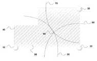
- FIG. 1is a diagram of the sensor's configuration in a protected region.
- FIG. 2is a block diagram of the present invention.
- FIG. 1shows a protected region 80 with perimeter 40 .
- the motion sensors 10 , 20 , and 30are placed in the region 80 as shown.
- the motion sensors 10 - 30transmit a low frequency microwave signal that can be transmitted through walls.
- the microwave sensors 10 - 30detect reflected signals from moving objects, as well known to one skilled in the art.
- RF/microwave ranging sensor of U.S. patent application Ser. No. 12/174,807 filed Jul. 17, 2008 entitled MICROWAVE RANGING SENSOR, which is owned by the assignee of the present application and incorporated by reference herein,can be used in the preferred embodiment for calculating the distance to the target and for discriminating movement of a human.
- the calculated distance from sensor 10is shown by arc 50 ; the calculated distance from sensor 20 is shown by arc 60 ; and the calculated distance from sensor 30 is shown by arc 70 .
- FIG. 2shows a block diagram of the operation of the security system of the present invention.
- the security systemdetermines the distance 110 - 130 for each sensor 10 - 30 .
- the three distancesare triangulated 150 to determine a two dimensional accurate location 90 (in FIG. 1 ).
- the step of triangulation 150is known to one skilled in the art. Since the field of view of the sensors 10 - 30 extends past the perimeter 40 , the location 90 may or may not be within the protected region 80 .
- the security system of the present inventionneeds a minimum of three motion sensors 10 - 30 and processing circuitry to monitor the activity of a target.
- the processing circuitry(not shown) performs the function of determining the distance 110 - 130 , triangulation 150 , analysis to determine action taken 100 , selecting a stored pattern 160 and storing the perimeter data 180 .
- the processor circuitryalso controls the generation of a warning signal 190 , the generation of an alarm signal 200 , and the display of the targets 210 .
- the security systemmore reliably detects the target because the system has the ability to detect the target location and track it so that the weakness of current security systems is overcome. Other types of sensors are unnecessary, and therefore the security system is not compromised by the inherent weakness of those detectors.
- the processing circuitrycollects accurate target locations 90 over a period of time to determine the target's activity.
- the analysis of the activity 100allows the security system to eliminate false alarms and determine the action to be taken.
- the target activitycan be displayed 210 on an LCD display.
- the displayshows targets inside and outside the protected region 80 and may also be useful for firefighters when determining the location of an occupant of a region.
- the analysis 100generates an alarm 200 .
- the analysis 100can also predict an intrusion and generate a warning signal 190 that alerts the occupants of the region 80 and discourages a target from intruding by using, for example, well-known X10 technology to control outside/inside lights and outside/inside sounds.
- the analysis 100 of a target's activityuses perimeter data 180 entered by an installer during installation and the selected mode of operation 140 entered by the user.
- the perimeter data 180includes stored property perimeter and map data.
- the perimeter map data 180is programmed by entering the installation mode 170 , inputting the relative coordinates for the locations of each sensor, and then walking along the perimeter 40 of the protected region 80 .
- the analysis 100uses the perimeter data 180 to determine when the target is inside or outside the protect space 80 .
- the selected mode of operation 140which may be daytime mode (high security) or nighttime mode (low security), corresponds to a stored pattern 160 that the analysis 100 uses to determine what action should be taken.
- the stored pattern 160 for the daytime mode of operationwould cause the security system to generate an alarm 200 for any motion inside the protected region 80 or after a predetermined delay time when there is a transition from outside the protected region 80 to inside the protected region 80 through the entry way only.
- the delay timeallows a security code to be entered into a keypad when an authorized user returns.
- the stored pattern for nighttime mode 160will not generate an alarm 200 when there is motion within the protected region 80 and will generate an alarm 200 immediately when there has been a transition from outside the protected region 80 to inside the protected region 80 .
- the stored pattern 160 corresponding to nighttime modedoes not generate an alarm 200 when there is a transition from inside the protected region 80 to outside the protected region 80 .
- a warning signal 190is generated when a target outside the protected region 80 is within a predetermined distance of the protected region 80 .
- the stored pattern 160 corresponding to nighttime modeallows the user to open doors and windows without generating an alarm 200 . Therefore, a homeowner can open windows while sleeping and his or her property is still protected.
- the stored patterns 160may comprise many more modes of operation and may be accomplished by a number of methods. These methods may include state tables, separate software routines, look up tables, dip switches, or remote control.
- the mode of operation 140may be automatically selected based on the time of day rather than selected by a user.
- the stored perimeter map data 180may include more information, such as the location of doors and windows. This additional information may be compared against additional stored patterns 160 to determine which action should be taken 100 .
Landscapes
- Physics & Mathematics (AREA)
- General Physics & Mathematics (AREA)
- Engineering & Computer Science (AREA)
- Computer Security & Cryptography (AREA)
- Burglar Alarm Systems (AREA)
- Radar Systems Or Details Thereof (AREA)
Abstract
Description
Claims (18)
Priority Applications (1)
| Application Number | Priority Date | Filing Date | Title |
|---|---|---|---|
| US12/198,942US7978069B2 (en) | 2008-08-27 | 2008-08-27 | Reliable security system by triangulation |
Applications Claiming Priority (1)
| Application Number | Priority Date | Filing Date | Title |
|---|---|---|---|
| US12/198,942US7978069B2 (en) | 2008-08-27 | 2008-08-27 | Reliable security system by triangulation |
Publications (2)
| Publication Number | Publication Date |
|---|---|
| US20100052902A1 US20100052902A1 (en) | 2010-03-04 |
| US7978069B2true US7978069B2 (en) | 2011-07-12 |
Family
ID=41724506
Family Applications (1)
| Application Number | Title | Priority Date | Filing Date |
|---|---|---|---|
| US12/198,942Active2029-10-03US7978069B2 (en) | 2008-08-27 | 2008-08-27 | Reliable security system by triangulation |
Country Status (1)
| Country | Link |
|---|---|
| US (1) | US7978069B2 (en) |
Cited By (4)
| Publication number | Priority date | Publication date | Assignee | Title |
|---|---|---|---|---|
| US8665084B2 (en) | 2011-07-29 | 2014-03-04 | Adt Us Holdings, Inc. | Security system and method |
| US9501924B2 (en) | 2014-12-30 | 2016-11-22 | Google Inc. | Home security system with automatic context-sensitive transition to different modes |
| US9747769B2 (en) | 2014-12-30 | 2017-08-29 | Google Inc. | Entry point opening sensor |
| US9940798B2 (en) | 2014-12-30 | 2018-04-10 | Google Llc | Alarm arming with open entry point |
Families Citing this family (7)
| Publication number | Priority date | Publication date | Assignee | Title |
|---|---|---|---|---|
| CN102262808B (en)* | 2011-07-15 | 2012-11-14 | 宁波讯强电子科技有限公司 | Acousto-magnetic anti-theft label, and volume label made of same and preparation method thereof |
| KR101820497B1 (en)* | 2011-07-27 | 2018-01-22 | 삼성디스플레이 주식회사 | Display device and method of driving the same |
| US9811989B2 (en)* | 2014-09-30 | 2017-11-07 | The Boeing Company | Event detection system |
| CN107221133B (en)* | 2016-03-22 | 2018-12-11 | 杭州海康威视数字技术股份有限公司 | A kind of area monitoring alarm system and alarm method |
| US9940826B1 (en)* | 2017-02-22 | 2018-04-10 | Honeywell International Inc. | Sensor data processing system for various applications |
| US10325463B2 (en)* | 2017-11-09 | 2019-06-18 | Ademco Inc. | Systems and methods for changing an operation of a security system in response to comparing a first unique identifier and a second unique identifier |
| US10512801B2 (en)* | 2018-04-20 | 2019-12-24 | Honeywell International Inc. | Distance-learning safety retraction lanyard |
Citations (6)
| Publication number | Priority date | Publication date | Assignee | Title |
|---|---|---|---|---|
| US5786760A (en) | 1995-03-08 | 1998-07-28 | Suzuki; Tomohiko | Alarm system with variable warning signal |
| US6307475B1 (en) | 1999-02-26 | 2001-10-23 | Eric D. Kelley | Location method and system for detecting movement within a building |
| US6380882B1 (en)* | 1999-07-03 | 2002-04-30 | Siemens Building Technologies Ag | Motion detector based on the doppler principle |
| US20040032326A1 (en)* | 2002-08-13 | 2004-02-19 | Hiroaki Nakamura | Intruder detection device and intruder detection method |
| US7084761B2 (en) | 2001-12-19 | 2006-08-01 | Hitachi, Ltd. | Security system |
| US20070120667A1 (en)* | 2000-03-10 | 2007-05-31 | Radio Systems Corporation | Piezoelectric Cable-Based Monitoring System |
- 2008
- 2008-08-27USUS12/198,942patent/US7978069B2/enactiveActive
Patent Citations (7)
| Publication number | Priority date | Publication date | Assignee | Title |
|---|---|---|---|---|
| US5786760A (en) | 1995-03-08 | 1998-07-28 | Suzuki; Tomohiko | Alarm system with variable warning signal |
| US6307475B1 (en) | 1999-02-26 | 2001-10-23 | Eric D. Kelley | Location method and system for detecting movement within a building |
| US6380882B1 (en)* | 1999-07-03 | 2002-04-30 | Siemens Building Technologies Ag | Motion detector based on the doppler principle |
| US20070120667A1 (en)* | 2000-03-10 | 2007-05-31 | Radio Systems Corporation | Piezoelectric Cable-Based Monitoring System |
| US7084761B2 (en) | 2001-12-19 | 2006-08-01 | Hitachi, Ltd. | Security system |
| US20040032326A1 (en)* | 2002-08-13 | 2004-02-19 | Hiroaki Nakamura | Intruder detection device and intruder detection method |
| US6909370B2 (en)* | 2002-08-13 | 2005-06-21 | Optex Co., Ltd. | Intruder detection device and intruder detection method |
Cited By (12)
| Publication number | Priority date | Publication date | Assignee | Title |
|---|---|---|---|---|
| US8665084B2 (en) | 2011-07-29 | 2014-03-04 | Adt Us Holdings, Inc. | Security system and method |
| US9117349B2 (en) | 2011-07-29 | 2015-08-25 | Adt Us Holdings, Inc. | Security system having segregated operating software |
| US9286772B2 (en) | 2011-07-29 | 2016-03-15 | Adt Us Holdings, Inc. | Security system and method |
| US9589441B2 (en) | 2011-07-29 | 2017-03-07 | Adt Us Holdings, Inc. | Security system and method |
| US9501924B2 (en) | 2014-12-30 | 2016-11-22 | Google Inc. | Home security system with automatic context-sensitive transition to different modes |
| US9558639B2 (en) | 2014-12-30 | 2017-01-31 | Google Inc. | Systems and methods of intrusion detection |
| US9672705B2 (en) | 2014-12-30 | 2017-06-06 | Google Inc. | Systems and methods of intrusion detection |
| US9747769B2 (en) | 2014-12-30 | 2017-08-29 | Google Inc. | Entry point opening sensor |
| US9940798B2 (en) | 2014-12-30 | 2018-04-10 | Google Llc | Alarm arming with open entry point |
| US10127785B2 (en) | 2014-12-30 | 2018-11-13 | Google Llc | Entry point opening sensor |
| US10290191B2 (en)* | 2014-12-30 | 2019-05-14 | Google Llc | Alarm arming with open entry point |
| US10339773B2 (en) | 2014-12-30 | 2019-07-02 | Google Llc | Home security system with automatic context-sensitive transition to different modes |
Also Published As
| Publication number | Publication date |
|---|---|
| US20100052902A1 (en) | 2010-03-04 |
Similar Documents
| Publication | Publication Date | Title |
|---|---|---|
| US7978069B2 (en) | Reliable security system by triangulation | |
| US8120524B2 (en) | Motion detection systems using CW radar in combination with additional sensors | |
| US9311793B2 (en) | Motion and area monitoring system and method | |
| EP1793356B1 (en) | Microwave smart motion sensor for security applications | |
| US10366585B2 (en) | Method for operating a surface treatment device | |
| US10403110B2 (en) | Access control system for use in restricted areas and industrial environments | |
| EP2980609A1 (en) | Electrostatic field sensor and security system in interior and exterior spaces | |
| US8004451B2 (en) | Adaptive microwave security sensor | |
| US20080042824A1 (en) | System and method for intruder detection | |
| US20030222809A1 (en) | Millimeter wave radar monitoring system | |
| KR101507238B1 (en) | Radar apparatus | |
| WO1999027335A1 (en) | Object presence detection using dual wavelength bands | |
| US9613510B2 (en) | Apparatus and method for rapid human detection with pet immunity | |
| EP4150598B1 (en) | Detecting an object in an environment | |
| KR102334015B1 (en) | Public toilet security system | |
| US10438464B1 (en) | Systems and methods for determining and verifying a presence of an object or an intruder in a secured area | |
| US7671739B2 (en) | System and method for implementing ranging microwave for detector range reduction | |
| KR20160139637A (en) | Security System using UWB RADAR | |
| JP2011215772A (en) | Object detection sensor | |
| KR101729485B1 (en) | Window monitoring device using radar sensors | |
| JP2004233157A (en) | Method of judging radar environment and object, and radar environment judging system | |
| JP2001229471A (en) | Trespass detecting device | |
| KR101828244B1 (en) | System and method for monitoring structure | |
| EP1107204A2 (en) | Infra-red monitoring system | |
| RU2697622C1 (en) | Method for combination of detection equipment for protection of perimeters and territories of objects |
Legal Events
| Date | Code | Title | Description |
|---|---|---|---|
| AS | Assignment | Owner name:HONEYWELL INTERNATIONAL INC.,NEW YORK Free format text:ASSIGNMENT OF ASSIGNORS INTEREST;ASSIGNOR:WU, XIAODONG;REEL/FRAME:021446/0452 Effective date:20080826 Owner name:HONEYWELL INTERNATIONAL INC., NEW YORK Free format text:ASSIGNMENT OF ASSIGNORS INTEREST;ASSIGNOR:WU, XIAODONG;REEL/FRAME:021446/0452 Effective date:20080826 | |
| STCF | Information on status: patent grant | Free format text:PATENTED CASE | |
| FPAY | Fee payment | Year of fee payment:4 | |
| AS | Assignment | Owner name:JPMORGAN CHASE BANK, N.A., AS ADMINISTRATIVE AGENT, NEW YORK Free format text:SECURITY INTEREST;ASSIGNOR:ADEMCO INC.;REEL/FRAME:047337/0577 Effective date:20181025 Owner name:JPMORGAN CHASE BANK, N.A., AS ADMINISTRATIVE AGENT Free format text:SECURITY INTEREST;ASSIGNOR:ADEMCO INC.;REEL/FRAME:047337/0577 Effective date:20181025 | |
| AS | Assignment | Owner name:ADEMCO INC., MINNESOTA Free format text:ASSIGNMENT OF ASSIGNORS INTEREST;ASSIGNOR:HONEYWELL INTERNATIONAL INC.;REEL/FRAME:047909/0425 Effective date:20181029 | |
| MAFP | Maintenance fee payment | Free format text:PAYMENT OF MAINTENANCE FEE, 8TH YEAR, LARGE ENTITY (ORIGINAL EVENT CODE: M1552); ENTITY STATUS OF PATENT OWNER: LARGE ENTITY Year of fee payment:8 | |
| AS | Assignment | Owner name:ADEMCO INC., MINNESOTA Free format text:CORRECTIVE ASSIGNMENT TO CORRECT THE PREVIOUS RECORDING BY NULLIFICATION. THE INCORRECTLY RECORDED PATENT NUMBERS 8545483, 8612538 AND 6402691 PREVIOUSLY RECORDED AT REEL: 047909 FRAME: 0425. ASSIGNOR(S) HEREBY CONFIRMS THE ASSIGNMENT;ASSIGNOR:HONEYWELL INTERNATIONAL INC.;REEL/FRAME:050431/0053 Effective date:20190215 | |
| MAFP | Maintenance fee payment | Free format text:PAYMENT OF MAINTENANCE FEE, 12TH YEAR, LARGE ENTITY (ORIGINAL EVENT CODE: M1553); ENTITY STATUS OF PATENT OWNER: LARGE ENTITY Year of fee payment:12 | |
| AS | Assignment | Owner name:RESIDEO LLC, DELAWARE Free format text:CHANGE OF NAME;ASSIGNOR:ADEMCO INC.;REEL/FRAME:071546/0001 Effective date:20241227 |