US7977648B2 - Scanning aperture ion beam modulator - Google Patents
Scanning aperture ion beam modulatorDownload PDFInfo
- Publication number
- US7977648B2 US7977648B2US12/305,554US30555408AUS7977648B2US 7977648 B2US7977648 B2US 7977648B2US 30555408 AUS30555408 AUS 30555408AUS 7977648 B2US7977648 B2US 7977648B2
- Authority
- US
- United States
- Prior art keywords
- shutter
- control
- longitudinal
- blades
- ion beam
- Prior art date
- Legal status (The legal status is an assumption and is not a legal conclusion. Google has not performed a legal analysis and makes no representation as to the accuracy of the status listed.)
- Active, expires
Links
Images


Classifications
- A—HUMAN NECESSITIES
- A61—MEDICAL OR VETERINARY SCIENCE; HYGIENE
- A61N—ELECTROTHERAPY; MAGNETOTHERAPY; RADIATION THERAPY; ULTRASOUND THERAPY
- A61N5/00—Radiation therapy
- A61N5/10—X-ray therapy; Gamma-ray therapy; Particle-irradiation therapy
- A—HUMAN NECESSITIES
- A61—MEDICAL OR VETERINARY SCIENCE; HYGIENE
- A61N—ELECTROTHERAPY; MAGNETOTHERAPY; RADIATION THERAPY; ULTRASOUND THERAPY
- A61N5/00—Radiation therapy
- A61N5/10—X-ray therapy; Gamma-ray therapy; Particle-irradiation therapy
- A61N2005/1085—X-ray therapy; Gamma-ray therapy; Particle-irradiation therapy characterised by the type of particles applied to the patient
- A61N2005/1087—Ions; Protons
- A—HUMAN NECESSITIES
- A61—MEDICAL OR VETERINARY SCIENCE; HYGIENE
- A61N—ELECTROTHERAPY; MAGNETOTHERAPY; RADIATION THERAPY; ULTRASOUND THERAPY
- A61N5/00—Radiation therapy
- A61N5/10—X-ray therapy; Gamma-ray therapy; Particle-irradiation therapy
- A61N2005/1092—Details
- A61N2005/1095—Elements inserted into the radiation path within the system, e.g. filters or wedges
- A—HUMAN NECESSITIES
- A61—MEDICAL OR VETERINARY SCIENCE; HYGIENE
- A61N—ELECTROTHERAPY; MAGNETOTHERAPY; RADIATION THERAPY; ULTRASOUND THERAPY
- A61N5/00—Radiation therapy
- A61N5/10—X-ray therapy; Gamma-ray therapy; Particle-irradiation therapy
- A61N5/103—Treatment planning systems
- G—PHYSICS
- G21—NUCLEAR PHYSICS; NUCLEAR ENGINEERING
- G21K—TECHNIQUES FOR HANDLING PARTICLES OR IONISING RADIATION NOT OTHERWISE PROVIDED FOR; IRRADIATION DEVICES; GAMMA RAY OR X-RAY MICROSCOPES
- G21K1/00—Arrangements for handling particles or ionising radiation, e.g. focusing or moderating
- G21K1/02—Arrangements for handling particles or ionising radiation, e.g. focusing or moderating using diaphragms, collimators
- G21K1/04—Arrangements for handling particles or ionising radiation, e.g. focusing or moderating using diaphragms, collimators using variable diaphragms, shutters, choppers
- G21K1/046—Arrangements for handling particles or ionising radiation, e.g. focusing or moderating using diaphragms, collimators using variable diaphragms, shutters, choppers varying the contour of the field, e.g. multileaf collimators
Definitions
- the present inventionrelates to radiation therapy systems using ions, such as protons, for the treatment of cancer and the like and, in particular, to a system providing improved modulation of an ion beam.
- External beam radiation therapymay treat a tumor within the patient by directing high-energy radiation in one or more beams toward the tumor.
- Recent advanced external beam radiation systemsfor example, as manufactured by Tomotherapy, Inc., treat a tumor with multiple x-ray fan beams directed at the patient over an angular range of 360°.
- Each of the beamsis comprised of individually modulated beamlets whose intensities can be controlled so that the combined effect of the beamlets, over the range of angles, allows an arbitrarily complex treatment area to be irradiated.
- X-raysdeposit energy in tissue along the entire path between the x-ray source and the exit point in the patient. While judicious selection of the angles and intensities of the x-ray beamlets can minimize radiation applied to healthy tissue outside of the tumor, inevitability of irradiating healthy tissue along the path to the tumor has suggested the use of ions such as protons as a substitute for x-ray radiation. Unlike x-rays, protons may be controlled to stop within the tissue, reducing or eliminating exit dose through healthy tissue on the far side of the tumor. Further, the dose deposited by a proton beam is not uniform along the entrance path of the beam, but rises substantially to a “Bragg peak” near a point where the proton beam stops within the tissue. The placement of Bragg peaks inside the tumor allows for improved sparing of normal tissue for proton treatments relative to x-ray treatments.
- radiation therapy with protons or other ionsallows separate control of intensity (i.e., the number of protons per second within an area) and energy (i.e., the speed of the protons).
- intensityi.e., the number of protons per second within an area
- energyi.e., the speed of the protons.
- Control of the intensity and time of exposuredetermines the total dose delivered by the protons to tissue, while control of the energy of the protons, by virtue of the Bragg peak described above, controls the depth of the exposure within the tissue.
- the proton beamremains narrowly collimated in a “pencil beam” and is steered in angle and adjusted in range to deposit the dose as a small spot within the patient.
- the spotis moved through the tumor in successive exposures until an arbitrary tumor volume has been irradiated.
- This approachis potentially very accurate, but because the tumor is treated in successive exposures, is slower than the first approach. Further the small spot sizes create the risk of uneven dose placement or “cold spots” should there be patient movement between exposures.
- the present inventionprovides the benefit of a scanning pencil beam while greatly increasing treatment speed. This is done by using a beam modulator that takes an area beam (as opposed to a pencil beam) and effectively creates multiple independent pencil beams that may simultaneously treat the patient.
- the modulatormay independently control both intensity and energy of each pencil beam, reducing or eliminating the need for a custom compensator.
- the present inventionemploys an area beam of ions directed along an axis and having a longitudinal and latitudinal extent in cross-section.
- the area beamis controllably occluded with a set of longitudinally opposed latitudinally adjacent shutter pairs, each shutter of each pair controllable and extendable to different longitudinal distances.
- the shuttersmay thus simultaneously control multiple discrete beams, which are actually portions of the area ion beam, at different adjacent latitudinal positions with controllably independent longitudinal positions.
- the shuttersmay control either or both the intensity and energy of the ion beams.
- Each shutter pairmay comprise opposed shutters that can fully block the ion beam from passing through the shutter.
- the shutter pairscan be moved to control a dwell time of an aperture formed between the shutters to control the intensity of the ion beam at a variety of longitudinal locations.
- the shutter pairsmay be controlled to move a center of an aperture created between the shutter pairs and to change a longitudinal separation between the shutter pairs.
- Each shuttermay be constructed of multiple blades, each sized to only partially block the ion beam from passing through the blade.
- the multiple bladesmay be independently adjusted to control an amount of overlap among the blades and a longitudinal location of the overlap to in turn control the energy of the ion beam at a variety of longitudinal locations.
- the multiple blades of each shutter pair when fully overlapping along an axis of the ion beammay fully block passage of the ion beam, and the multiple blades of each shutter pair may be further controlled to control a dwell time of an aperture formed between the multiple blades to control the intensity of the ion beam at a variety of longitudinal locations.
- the area beammay have a non-uniform intensity distribution and the dwell time may be controlled according to the non-uniform intensity distribution and the desired treatment intensity to correct for the non-uniform intensity distribution.
- the blades of each shutter pairhave equal thicknesses.
- the equal thickness shuttersallow a complex, energy profile to be developed.
- the term “equal thickness”is intended to include shutters of different materials and different thickness so as to operate as if they were of equal thicknesses of a single material.
- the blades of each shutter pairmay have different according to a binary sequence.
- the area beammay be rotated about a patient to provide treatment of the patient at a plurality of angles.
- FIG. 1is a simplified representation of a proton therapy machine suitable for use with the present invention and having a rotating gantry and a modulator directing multiple independent pencil beams of protons toward a patient support at a range of angles;
- FIG. 2is an exploded isometric representation of a first embodiment of the modulator using multiple, ion-opaque modulation elements for controlling the intensity of the individual pencil beams;
- FIG. 3is a side elevational view of one modulation element showing movement of a shutter pair for intensity modulation
- FIG. 4is a figure similar to that of FIG. 3 showing the movement of the shutter pair for beam width control
- FIG. 5is a figure similar to that of FIG. 2 showing a second embodiment of the modulator having multiple, energy attenuating modulation elements for controlling the energy of the individual pencil beams and optionally including the modulator of FIG. 2 ;
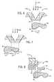
- FIG. 6is a figure similar to that of FIG. 3 showing one shutter of the modulation element of FIG. 5 composed of blades having equal thickness and used to create a piecewise compensator for a tumor;
- FIG. 7is a figure similar to that of FIG. 6 showing a shifting of the blades of the modulator element with respect to FIG. 6 for creation of the piecewise compensator;
- FIG. 8is a figure similar to that of FIG. 6 showing blades with varying thickness used for energy control of a pencil beam.
- FIG. 9is a side elevational view of an intensity variation along a longitudinal axis through the area beam and showing use of the blades of FIG. 6 for both intensity and energy control according to the variable intensity of the area beam.
- a proton therapy machine 10may include a gantry 12 having a modulator 14 , both of which may orbit 16 about a patient (not shown) who is supported on a patient support table 18 .
- the modulator 14receives a source of protons from a proton source conduit 22 that may conduct protons from a synchrotron, cyclotron or the like and, by means of bending magnets 23 , direct them toward the patient support table 18 at all positions within the orbit 16 .
- the protons from the proton source conduit 22will generally be narrowly collimated to a pencil beam (not shown) when received by the modulator 14 .
- the modulator 14spreads the pencil beam into an area beam radiating along an axis 20 , and individually modulates independently positionable beamlets 24 (e.g., pencil beams) in energy and intensity.
- the beamlets 24are controlled by a control computer 25 communicating with the modulator 14 , the control computer 25 executing a stored program 26 to provide control signals to the modulator 14 according to stored treatment sinograms 27 indicating desired intensities and energies of the individual beamlets 24 as a function of the angle of the gantry 12 in orbit 16 .
- the modulator 14receives a pencil beam 30 along axis 21 and directs it to an energy modulator 32 , in this case, being a pair of opposed wedges 34 a and 34 b . These two wedges 34 a and 34 b overlap to present a rectangular cross-section within the beam 30 .
- the amount of overlap, and thus the thickness of the cross-section,is controlled by moving the wedges 34 a and 34 b to increasing or decreasing overlap by means of electrically controlled actuators 36 , the latter receiving signals from computer 25 .
- the thickness of wedge material within the beam 30controls the energy of the proton in the exiting energy modulated pencil beam 30 ′.
- An alternative energy modulator(not shown) is a dielectric wall accelerator which can adjust the acceleration of the ions electrically thus eliminating the neutron production incident to systems that reduce energy of an existing ion beam.
- the energy modulated pencil beam 30 ′may next be received by a scattering foil 38 which spreads the pencil beam 30 ′ into an area beam 40 .
- the area beam 40radiates along axis 21 spreading in a longitudinal extent 44 and a latitudinal extent 46 .
- the latitudinal extent 46will be parallel to an axis of the orbit 16 , however the opposite orientation with the longitudinal extent 44 parallel with the axis of the orbit 16 may also be used.
- the area beam 40may be masked to a rectangular cross-sectional area 43 by collimator 42 to be received by an area modulator 59 including a set of shutter pairs 51 forming independent modulation elements.
- the shutter pairs 51are latitudinally adjacent to each other so that when the shutters are closed (as will be described) they fully fill the cross-sectional area 43 .
- Each shutter pair 51includes a left and right shutter 50 a and 50 b , respectively, the shutters 50 a and 50 b extending longitudinally and independently movable in the longitudinal direction toward and away to define a controllable aperture 52 therebetween.
- the aperture 52 thus formedmay be controlled in longitudinal width and longitudinal center-point location.
- each shutter 50 a and 50 bwill be opaque to the proton beam, blocking all radiation except that passing through the aperture 52 as beamlet 24 . Accordingly, the shutter pairs 51 together convert the area beam 40 into a plurality of independently controllable beamlets 24 corresponding to each aperture 52 . In operation the apertures 52 , and hence the beamlets 24 , will be scanned longitudinally as indicated by direction arrow 58 .
- each shutter 50 a and 50 bis controlled by a respective actuator 56 electrically communicating with the computer 25 .
- the average intensity 60 of radiation directed toward the patient from the beamlet 24may be controlled as inversely related to the velocity 62 .
- the total proton flux, and thus doseincreases correspondingly.
- multiple beamlets 24 generated by the modulator 14may have their scanning speed independently controlled to independently control the dose delivered by each of the beamlets 24 . This control may be done in parallel so treatment by each beamlet 24 may occur simultaneously.
- the ability to move the shutters 50 a and 50 b independentlyalso allows the longitudinal size of the aperture 52 to be changed. This allows widening the aperture when longitudinally adjacent portions of the tumor require identical treatment resulting in a greater efficiency of treatment. For example if an intensity 60 ′ has a plateau portion 63 with essentially constant longitudinal intensity, the beamlet 24 may be widened to equal the width of this plateau portion 63 , decreasing treatment time over that which would be required by separate sequential treatments using narrower beamlets 24 .
- the energy modulator 32may be eliminated and the pencil beam 30 may be received directly by a scattering foil 38 (or the like) to generate the area beam 40 .
- the area beam 40may then be received (after collimation to a rectangular area by collimator 42 , not shown) by an energy modulator 70 .
- the energy modulator 70also includes shutter pairs 51 providing corresponding modulation elements.
- Each shutter pair 51may again include opposed, longitudinally extending shutters 50 a and 50 b that may be moved toward and away from each other by actuators 56 .
- each shutter 50 a and 50 bis comprised of a number of independently movable blades 74 that overlap along the direction of axis 21 .
- the actuators 56may independently move each of the blades 74 of shutters 50 a and 50 b.
- each shutter pair 51may create an aperture independently controlling one latitudinal beamlet 24 (not shown in FIG. 5 ).
- the blades 74 of each shutter 50 a and 50 bmay be of equal width along the axis 21 , and each blade 74 sized to attenuate the energy in, but not wholly block, the protons of the area beam 40 .
- the blades 74may be staggered with respect to their overlap along axis 21 to create a thickness through which the area beam 40 must pass that vary longitudinally in the manner of an energy controlling compensator.
- the exact amount of curvaturemay be controlled by controlling the exact amounts of overlap of the blades 74 , while only a convex dose limit 76 may be created with these blades and 74 .
- a tumor 80 with an arbitrarily complex shapemay be treated by dividing the tumor 80 into several regions 78 and 82 each of which is independently convex.
- the blades 74may then be shifted to provide separate treatment of each region 78 and 82 in a piecewise fashion.
- the treatment of first region 78is shown in FIG. 6 and the treatment of second region 82 is shown in FIG. 7 .
- the particular shape of the convex dose limit 76is controlled by computer 25 controlling the actuators 56 .
- the shutter elements 51may employ blades 74 ′ having different widths or effective widths (e.g., different attenuation) such that their individual attentions stand, for example, in a base-2 power sequence.
- each blade 74 starting at the least attenuating blade 74may attenuate twice as strongly as the previous blade 74 with which it may overlap. In this way, the minimum number of blades 74 can be used to create the maximum number of energy steps in the beamlet 24 .
- a pair of opposed shutters 50 a and 50 b each having multiple blades 74may be used, or, as shown, a single shutter 50 a of energy attenuating blades 74 may be used together with two shutters 50 a and 50 b of ion blocking blades 74 ′′ used for intensity modulation.
- the use of the binary weighted blades 74does not allow an intuitive generation of a compensator per the approach of FIGS. 6 and 7 but allows complete control of the energy of the beamlet 24 that may be scanned as described generally in the embodiment of FIG. 2 to create an arbitrary convex dose limit 76 in a tumor 80 .
- the scanningis conducted by simultaneous movement of a single set of blades 74 within a beamlet 24 defined by ion-opaque blades 74 of shutters 50 a and 50 b of an area modulator 59 optionally positioned as shown in FIG. 5 .
- the ability of the present invention to control the intensity of the area beam 40 at different longitudinal and latitudinal positionsallows the invention to correct for an irregular intensity profile 90 of the area beam 40 by action of the shutter pairs 51 .
- the shutter system of FIGS. 6 and 7may be used to control both intensity and energy by selecting energy attenuating blades 74 that fully block the area beam 40 when all blades 74 overlap.
- the intensity profile 90is measured and divided into longitudinal bands 92 where the intensity may be approximated as uniform.
- the width of the bands 92is determined by the amount of intensity variation that can be tolerated.
- each band 92its latitudinal extent is used to define a treatment region 94 , the different treatment regions 94 separately treated in sequence.
- the blades 74 of each of shutters 50 a and 50 bare closed against each other to fully block the area beam 40 .
- the interface between the blades 74may be aligned with the center of the first treatment region 94 .
- the blades 74are retracted about the center line to create a desired compensator shape assuming a uniform intensity of the area beam within the region 94 equal to its average intensity within the band 92 .
- the blades 74are closed against each other again to fully block the area beam 40 . Their interface may then be aligned with a second band 92 and this process repeated.
- the amount of time between time 96 and 102controls the intensity of radiation within the treatment region 94 , whereas the staggering of the blades 74 during time 100 controls the energy distribution and thus the depth profile of the protons.
- the improved treatment speed of the present invention and elimination of the need for multiple custom compensatorsallows multiple angles of treatment to be obtained by rotating the gantry 12 to different positions within the orbit 16 and applying the radiation as modulated by the present invention at each position.
- the orbit 16is a relative orbit with respect to the patient and, of course, may in fact be implemented by rotation of the patient in certain circumstances.
- the gantryshould be understood to be any system for making relative rotations between the patient and the beam.
Landscapes
- Health & Medical Sciences (AREA)
- Engineering & Computer Science (AREA)
- Biomedical Technology (AREA)
- Pathology (AREA)
- Nuclear Medicine, Radiotherapy & Molecular Imaging (AREA)
- Radiology & Medical Imaging (AREA)
- Life Sciences & Earth Sciences (AREA)
- Animal Behavior & Ethology (AREA)
- General Health & Medical Sciences (AREA)
- Public Health (AREA)
- Veterinary Medicine (AREA)
- Radiation-Therapy Devices (AREA)
Abstract
Description
Claims (25)
Priority Applications (1)
| Application Number | Priority Date | Filing Date | Title |
|---|---|---|---|
| US12/305,554US7977648B2 (en) | 2007-02-27 | 2008-02-27 | Scanning aperture ion beam modulator |
Applications Claiming Priority (3)
| Application Number | Priority Date | Filing Date | Title |
|---|---|---|---|
| US89185907P | 2007-02-27 | 2007-02-27 | |
| US12/305,554US7977648B2 (en) | 2007-02-27 | 2008-02-27 | Scanning aperture ion beam modulator |
| PCT/US2008/055090WO2008106492A1 (en) | 2007-02-27 | 2008-02-27 | Scanning aperture ion beam modulator |
Publications (2)
| Publication Number | Publication Date |
|---|---|
| US20090289192A1 US20090289192A1 (en) | 2009-11-26 |
| US7977648B2true US7977648B2 (en) | 2011-07-12 |
Family
ID=40451388
Family Applications (1)
| Application Number | Title | Priority Date | Filing Date |
|---|---|---|---|
| US12/305,554Active2029-03-12US7977648B2 (en) | 2007-02-27 | 2008-02-27 | Scanning aperture ion beam modulator |
Country Status (2)
| Country | Link |
|---|---|
| US (1) | US7977648B2 (en) |
| WO (1) | WO2008106492A1 (en) |
Cited By (30)
| Publication number | Priority date | Publication date | Assignee | Title |
|---|---|---|---|---|
| US20130274536A1 (en)* | 2010-04-02 | 2013-10-17 | Mitsubishi Electric Corporation | Particle beam irradiation apparatus and particle beam therapy system |
| US8791656B1 (en) | 2013-05-31 | 2014-07-29 | Mevion Medical Systems, Inc. | Active return system |
| US8907311B2 (en) | 2005-11-18 | 2014-12-09 | Mevion Medical Systems, Inc. | Charged particle radiation therapy |
| US8927950B2 (en) | 2012-09-28 | 2015-01-06 | Mevion Medical Systems, Inc. | Focusing a particle beam |
| US8933650B2 (en) | 2007-11-30 | 2015-01-13 | Mevion Medical Systems, Inc. | Matching a resonant frequency of a resonant cavity to a frequency of an input voltage |
| US8941083B2 (en) | 2007-10-11 | 2015-01-27 | Mevion Medical Systems, Inc. | Applying a particle beam to a patient |
| US8952634B2 (en) | 2004-07-21 | 2015-02-10 | Mevion Medical Systems, Inc. | Programmable radio frequency waveform generator for a synchrocyclotron |
| US8970137B2 (en) | 2007-11-30 | 2015-03-03 | Mevion Medical Systems, Inc. | Interrupted particle source |
| US9155186B2 (en) | 2012-09-28 | 2015-10-06 | Mevion Medical Systems, Inc. | Focusing a particle beam using magnetic field flutter |
| US9185789B2 (en) | 2012-09-28 | 2015-11-10 | Mevion Medical Systems, Inc. | Magnetic shims to alter magnetic fields |
| US9274067B2 (en) | 2011-03-07 | 2016-03-01 | Loma Linda University Medical Center | Systems, devices and methods related to calibration of a proton computed tomography scanner |
| US9301384B2 (en) | 2012-09-28 | 2016-03-29 | Mevion Medical Systems, Inc. | Adjusting energy of a particle beam |
| US9545528B2 (en) | 2012-09-28 | 2017-01-17 | Mevion Medical Systems, Inc. | Controlling particle therapy |
| US9622335B2 (en) | 2012-09-28 | 2017-04-11 | Mevion Medical Systems, Inc. | Magnetic field regenerator |
| US9661736B2 (en) | 2014-02-20 | 2017-05-23 | Mevion Medical Systems, Inc. | Scanning system for a particle therapy system |
| US9681531B2 (en) | 2012-09-28 | 2017-06-13 | Mevion Medical Systems, Inc. | Control system for a particle accelerator |
| US9723705B2 (en) | 2012-09-28 | 2017-08-01 | Mevion Medical Systems, Inc. | Controlling intensity of a particle beam |
| US9730308B2 (en) | 2013-06-12 | 2017-08-08 | Mevion Medical Systems, Inc. | Particle accelerator that produces charged particles having variable energies |
| US9950194B2 (en) | 2014-09-09 | 2018-04-24 | Mevion Medical Systems, Inc. | Patient positioning system |
| US9962560B2 (en) | 2013-12-20 | 2018-05-08 | Mevion Medical Systems, Inc. | Collimator and energy degrader |
| US10254739B2 (en) | 2012-09-28 | 2019-04-09 | Mevion Medical Systems, Inc. | Coil positioning system |
| US10258810B2 (en) | 2013-09-27 | 2019-04-16 | Mevion Medical Systems, Inc. | Particle beam scanning |
| US10646728B2 (en) | 2015-11-10 | 2020-05-12 | Mevion Medical Systems, Inc. | Adaptive aperture |
| US10653892B2 (en) | 2017-06-30 | 2020-05-19 | Mevion Medical Systems, Inc. | Configurable collimator controlled using linear motors |
| US10675487B2 (en) | 2013-12-20 | 2020-06-09 | Mevion Medical Systems, Inc. | Energy degrader enabling high-speed energy switching |
| US10925147B2 (en) | 2016-07-08 | 2021-02-16 | Mevion Medical Systems, Inc. | Treatment planning |
| US11103730B2 (en) | 2017-02-23 | 2021-08-31 | Mevion Medical Systems, Inc. | Automated treatment in particle therapy |
| US11141608B2 (en) | 2017-04-07 | 2021-10-12 | Massachusetts Institute Of Technology | Compact proton beam energy modulator |
| US11291861B2 (en) | 2019-03-08 | 2022-04-05 | Mevion Medical Systems, Inc. | Delivery of radiation by column and generating a treatment plan therefor |
| US12245355B2 (en) | 2021-02-19 | 2025-03-04 | Mevion Medical Systems, Inc. | Gantry for a particle therapy system |
Families Citing this family (7)
| Publication number | Priority date | Publication date | Assignee | Title |
|---|---|---|---|---|
| WO2008106496A1 (en)* | 2007-02-27 | 2008-09-04 | Wisconsin Alumni Research Foundation | Ion radiation therapy system with variable beam resolution |
| GB2463448B (en)* | 2008-07-09 | 2012-08-22 | Univ Manchester | Beam sensing |
| US8330132B2 (en)* | 2008-08-27 | 2012-12-11 | Varian Medical Systems, Inc. | Energy modulator for modulating an energy of a particle beam |
| DE102010048232B4 (en)* | 2010-10-12 | 2014-11-20 | Gsi Helmholtzzentrum Für Schwerionenforschung Gmbh | Irradiation planning with inhomogeneous particle beam |
| EP2532385B1 (en) | 2011-06-09 | 2015-04-22 | Ion Beam Applications S.A. | Shielding device for irradiation unit |
| US9855445B2 (en)* | 2016-04-01 | 2018-01-02 | Varian Medical Systems, Inc. | Radiation therapy systems and methods for delivering doses to a target volume |
| CN110382050B (en)* | 2017-01-05 | 2022-04-12 | 梅维昂医疗系统股份有限公司 | a particle therapy system |
Citations (52)
| Publication number | Priority date | Publication date | Assignee | Title |
|---|---|---|---|---|
| US4276477A (en) | 1979-09-17 | 1981-06-30 | Varian Associates, Inc. | Focusing apparatus for uniform application of charged particle beam |
| US5317616A (en) | 1992-03-19 | 1994-05-31 | Wisconsin Alumni Research Foundation | Method and apparatus for radiation therapy |
| US5394452A (en) | 1992-03-19 | 1995-02-28 | Wisconsin Alumni Research Foundation | Verification system for radiation therapy |
| US5625663A (en) | 1992-03-19 | 1997-04-29 | Wisconsin Alumni Research Foundation | Dynamic beam flattening apparatus for radiation therapy |
| US5661773A (en) | 1992-03-19 | 1997-08-26 | Wisconsin Alumni Research Foundation | Interface for radiation therapy machine |
| US5668371A (en) | 1995-06-06 | 1997-09-16 | Wisconsin Alumni Research Foundation | Method and apparatus for proton therapy |
| US5673300A (en) | 1996-06-11 | 1997-09-30 | Wisconsin Alumni Research Foundation | Method of registering a radiation treatment plan to a patient |
| US5724400A (en) | 1992-03-19 | 1998-03-03 | Wisconsin Alumni Research Foundation | Radiation therapy system with constrained rotational freedom |
| US5802136A (en) | 1994-05-17 | 1998-09-01 | Nomos Corporation | Method and apparatus for conformal radiation therapy |
| EP0986070A1 (en) | 1998-09-11 | 2000-03-15 | Gesellschaft für Schwerionenforschung mbH | Ion beam therapy system and a method for operating the system |
| JP2000214298A (en) | 1999-01-20 | 2000-08-04 | Mitsubishi Electric Corp | Charged particle beam irradiation apparatus, energy compensator used in the apparatus, and charged particle beam irradiation method |
| DE19907098A1 (en) | 1999-02-19 | 2000-08-24 | Schwerionenforsch Gmbh | Ion beam scanning system for radiation therapy e.g. for tumor treatment, uses energy absorption device displaced transverse to ion beam path via linear motor for altering penetration depth |
| EP1045399A1 (en) | 1999-04-12 | 2000-10-18 | GSI Gesellschaft für Schwerionenforschung mbH | Device and method for controlling a raster scanner in ion theraphy |
| WO2002007817A2 (en) | 2000-06-30 | 2002-01-31 | Gesellschaft für Schwerionenforschung mbH | Device for irradiating a tumor tissue |
| US6345114B1 (en) | 1995-06-14 | 2002-02-05 | Wisconsin Alumni Research Foundation | Method and apparatus for calibration of radiation therapy equipment and verification of radiation treatment |
| US6385286B1 (en) | 1998-08-06 | 2002-05-07 | Wisconsin Alumni Research Foundation | Delivery modification system for radiation therapy |
| WO2002041948A1 (en) | 2000-11-21 | 2002-05-30 | Gesellschaft für Schwerionenforschung mbH | Device and method for adapting the size of an ion beam spot in the domain of tumor irradiation |
| US6438202B1 (en) | 1998-08-06 | 2002-08-20 | Wisconsin Alumni Research Foundation | Method using post-patient radiation monitor to verify entrance radiation and dose in a radiation therapy machine |
| US20020136439A1 (en) | 2001-03-09 | 2002-09-26 | Ruchala Kenneth J. | System and method for fusion-aligned reprojection of incomplete data |
| US6560311B1 (en) | 1998-08-06 | 2003-05-06 | Wisconsin Alumni Research Foundation | Method for preparing a radiation therapy plan |
| US20030160189A1 (en) | 2002-02-28 | 2003-08-28 | Koji Matsuda | Charged particle beam irradiation apparatus |
| US6618467B1 (en) | 1999-04-02 | 2003-09-09 | Wisconsin Alumni Research Foundation | Megavoltage computed tomography during radiotherapy |
| US6636622B2 (en) | 1997-10-15 | 2003-10-21 | Wisconsin Alumni Research Foundation | Method and apparatus for calibration of radiation therapy equipment and verification of radiation treatment |
| US20030198319A1 (en) | 2002-04-22 | 2003-10-23 | Toth Thomas L. | Method and apparatus of modulating the filtering of radiation during radiographic imaging |
| US6661870B2 (en) | 2001-03-09 | 2003-12-09 | Tomotherapy Incorporated | Fluence adjustment for improving delivery to voxels without reoptimization |
| US6731970B2 (en) | 2000-07-07 | 2004-05-04 | Brainlab Ag | Method for breath compensation in radiation therapy |
| WO2005004168A1 (en) | 2003-07-01 | 2005-01-13 | National Institute Of Radiological Sciences | Range compensator and heavy charged particle beam irradiation system |
| US20050123092A1 (en) | 2001-12-14 | 2005-06-09 | Mistretta Charles A. | Virtual spherical anode computed tomography |
| US20050197564A1 (en) | 2004-02-20 | 2005-09-08 | University Of Florida Research Foundation, Inc. | System for delivering conformal radiation therapy while simultaneously imaging soft tissue |
| US20060226372A1 (en) | 2005-03-31 | 2006-10-12 | Masaki Yanagisawa | Charged particle beam extraction system and method |
| US20060285639A1 (en) | 2005-05-10 | 2006-12-21 | Tomotherapy Incorporated | System and method of treating a patient with radiation therapy |
| US20070029510A1 (en) | 2005-08-05 | 2007-02-08 | Siemens Aktiengesellschaft | Gantry system for a particle therapy facility |
| US20070036267A1 (en) | 2005-07-22 | 2007-02-15 | Becker Stewart J | Low skin dose patient positioning device for radiation treatment of prone breast |
| US20070041498A1 (en) | 2005-07-22 | 2007-02-22 | Olivera Gustavo H | System and method of remotely directing radiation therapy treatment |
| US20070041499A1 (en) | 2005-07-22 | 2007-02-22 | Weiguo Lu | Method and system for evaluating quality assurance criteria in delivery of a treatment plan |
| US20070041494A1 (en) | 2005-07-22 | 2007-02-22 | Ruchala Kenneth J | Method and system for evaluating delivered dose |
| US20070043286A1 (en) | 2005-07-22 | 2007-02-22 | Weiguo Lu | Method and system for adapting a radiation therapy treatment plan based on a biological model |
| US20070041500A1 (en) | 2005-07-23 | 2007-02-22 | Olivera Gustavo H | Radiation therapy imaging and delivery utilizing coordinated motion of gantry and couch |
| US20070041497A1 (en) | 2005-07-22 | 2007-02-22 | Eric Schnarr | Method and system for processing data relating to a radiation therapy treatment plan |
| US20070041495A1 (en) | 2005-07-22 | 2007-02-22 | Olivera Gustavo H | Method of and system for predicting dose delivery |
| WO2007021226A1 (en) | 2005-08-16 | 2007-02-22 | C-Rad Innovation Ab | Radiation modulator |
| US7186986B2 (en) | 2001-06-18 | 2007-03-06 | Wisconsin Alumni Research Foundation | Radiation detector with converters |
| US20070076846A1 (en) | 2005-07-22 | 2007-04-05 | Ruchala Kenneth J | System and method of delivering radiation therapy to a moving region of interest |
| US7207715B2 (en) | 2005-07-29 | 2007-04-24 | Upmc | Method to implement full six-degree target shift corrections in radiotherapy |
| US20070195930A1 (en) | 2005-07-22 | 2007-08-23 | Kapatoes Jeffrey M | System and method of generating contour structures using a dose volume histogram |
| US20070195929A1 (en) | 2005-07-22 | 2007-08-23 | Ruchala Kenneth J | System and method of evaluating dose delivered by a radiation therapy system |
| US20070195922A1 (en) | 2005-07-22 | 2007-08-23 | Mackie Thomas R | System and method of monitoring the operation of a medical device |
| US20070242801A1 (en) | 2005-04-01 | 2007-10-18 | Wisconsin Alumni Research Foundation | Small Field Intensity Modulated Radiation Therapy Machine |
| US7302038B2 (en) | 2004-09-24 | 2007-11-27 | Wisconsin Alumni Research Foundation | Correction of patient rotation errors in radiotherapy using couch translation |
| US20080260098A1 (en)* | 2007-02-27 | 2008-10-23 | Al-Sadah Jihad H | Areal modulator for intensity modulated radiation therapy |
| US20090200481A1 (en)* | 2007-02-27 | 2009-08-13 | Mackie Thomas R | Ion radiation therapy system having magnetic fan beam former |
| US7714309B2 (en)* | 2007-02-27 | 2010-05-11 | Wisconsin Alumni Research Foundation | Phantom for ion range detection |
- 2008
- 2008-02-27WOPCT/US2008/055090patent/WO2008106492A1/enactiveApplication Filing
- 2008-02-27USUS12/305,554patent/US7977648B2/enactiveActive
Patent Citations (59)
| Publication number | Priority date | Publication date | Assignee | Title |
|---|---|---|---|---|
| US4276477A (en) | 1979-09-17 | 1981-06-30 | Varian Associates, Inc. | Focusing apparatus for uniform application of charged particle beam |
| US5625663A (en) | 1992-03-19 | 1997-04-29 | Wisconsin Alumni Research Foundation | Dynamic beam flattening apparatus for radiation therapy |
| US5394452A (en) | 1992-03-19 | 1995-02-28 | Wisconsin Alumni Research Foundation | Verification system for radiation therapy |
| US5442675A (en) | 1992-03-19 | 1995-08-15 | Wisconsin Alumni Research Foundation | Dynamic collimator for radiation therapy |
| US5528650A (en) | 1992-03-19 | 1996-06-18 | Swerdloff; Stuart | Method and apparatus for radiation therapy |
| US5548627A (en) | 1992-03-19 | 1996-08-20 | Wisconsin Alumni Research Foundation | Radiation therapy system with constrained rotational freedom |
| US5661773A (en) | 1992-03-19 | 1997-08-26 | Wisconsin Alumni Research Foundation | Interface for radiation therapy machine |
| US5724400A (en) | 1992-03-19 | 1998-03-03 | Wisconsin Alumni Research Foundation | Radiation therapy system with constrained rotational freedom |
| US5317616A (en) | 1992-03-19 | 1994-05-31 | Wisconsin Alumni Research Foundation | Method and apparatus for radiation therapy |
| US5802136A (en) | 1994-05-17 | 1998-09-01 | Nomos Corporation | Method and apparatus for conformal radiation therapy |
| US5668371A (en) | 1995-06-06 | 1997-09-16 | Wisconsin Alumni Research Foundation | Method and apparatus for proton therapy |
| US6345114B1 (en) | 1995-06-14 | 2002-02-05 | Wisconsin Alumni Research Foundation | Method and apparatus for calibration of radiation therapy equipment and verification of radiation treatment |
| US5673300A (en) | 1996-06-11 | 1997-09-30 | Wisconsin Alumni Research Foundation | Method of registering a radiation treatment plan to a patient |
| US6636622B2 (en) | 1997-10-15 | 2003-10-21 | Wisconsin Alumni Research Foundation | Method and apparatus for calibration of radiation therapy equipment and verification of radiation treatment |
| US6385286B1 (en) | 1998-08-06 | 2002-05-07 | Wisconsin Alumni Research Foundation | Delivery modification system for radiation therapy |
| US6438202B1 (en) | 1998-08-06 | 2002-08-20 | Wisconsin Alumni Research Foundation | Method using post-patient radiation monitor to verify entrance radiation and dose in a radiation therapy machine |
| US6560311B1 (en) | 1998-08-06 | 2003-05-06 | Wisconsin Alumni Research Foundation | Method for preparing a radiation therapy plan |
| EP0986070A1 (en) | 1998-09-11 | 2000-03-15 | Gesellschaft für Schwerionenforschung mbH | Ion beam therapy system and a method for operating the system |
| JP2000214298A (en) | 1999-01-20 | 2000-08-04 | Mitsubishi Electric Corp | Charged particle beam irradiation apparatus, energy compensator used in the apparatus, and charged particle beam irradiation method |
| DE19907098A1 (en) | 1999-02-19 | 2000-08-24 | Schwerionenforsch Gmbh | Ion beam scanning system for radiation therapy e.g. for tumor treatment, uses energy absorption device displaced transverse to ion beam path via linear motor for altering penetration depth |
| US6618467B1 (en) | 1999-04-02 | 2003-09-09 | Wisconsin Alumni Research Foundation | Megavoltage computed tomography during radiotherapy |
| EP1045399A1 (en) | 1999-04-12 | 2000-10-18 | GSI Gesellschaft für Schwerionenforschung mbH | Device and method for controlling a raster scanner in ion theraphy |
| WO2002007817A2 (en) | 2000-06-30 | 2002-01-31 | Gesellschaft für Schwerionenforschung mbH | Device for irradiating a tumor tissue |
| US6731970B2 (en) | 2000-07-07 | 2004-05-04 | Brainlab Ag | Method for breath compensation in radiation therapy |
| WO2002041948A1 (en) | 2000-11-21 | 2002-05-30 | Gesellschaft für Schwerionenforschung mbH | Device and method for adapting the size of an ion beam spot in the domain of tumor irradiation |
| US6661870B2 (en) | 2001-03-09 | 2003-12-09 | Tomotherapy Incorporated | Fluence adjustment for improving delivery to voxels without reoptimization |
| US20020136439A1 (en) | 2001-03-09 | 2002-09-26 | Ruchala Kenneth J. | System and method for fusion-aligned reprojection of incomplete data |
| US6915005B1 (en) | 2001-03-09 | 2005-07-05 | Tomo Therapy Incorporated | Method for reconstruction of limited data images using fusion-aligned reprojection and normal-error-aligned reprojection |
| US7046831B2 (en) | 2001-03-09 | 2006-05-16 | Tomotherapy Incorporated | System and method for fusion-aligned reprojection of incomplete data |
| US7186986B2 (en) | 2001-06-18 | 2007-03-06 | Wisconsin Alumni Research Foundation | Radiation detector with converters |
| US20050123092A1 (en) | 2001-12-14 | 2005-06-09 | Mistretta Charles A. | Virtual spherical anode computed tomography |
| US20030160189A1 (en) | 2002-02-28 | 2003-08-28 | Koji Matsuda | Charged particle beam irradiation apparatus |
| US20030198319A1 (en) | 2002-04-22 | 2003-10-23 | Toth Thomas L. | Method and apparatus of modulating the filtering of radiation during radiographic imaging |
| WO2005004168A1 (en) | 2003-07-01 | 2005-01-13 | National Institute Of Radiological Sciences | Range compensator and heavy charged particle beam irradiation system |
| US20050197564A1 (en) | 2004-02-20 | 2005-09-08 | University Of Florida Research Foundation, Inc. | System for delivering conformal radiation therapy while simultaneously imaging soft tissue |
| US7302038B2 (en) | 2004-09-24 | 2007-11-27 | Wisconsin Alumni Research Foundation | Correction of patient rotation errors in radiotherapy using couch translation |
| US20060226372A1 (en) | 2005-03-31 | 2006-10-12 | Masaki Yanagisawa | Charged particle beam extraction system and method |
| US20070242801A1 (en) | 2005-04-01 | 2007-10-18 | Wisconsin Alumni Research Foundation | Small Field Intensity Modulated Radiation Therapy Machine |
| US20060285639A1 (en) | 2005-05-10 | 2006-12-21 | Tomotherapy Incorporated | System and method of treating a patient with radiation therapy |
| US20070104316A1 (en) | 2005-07-22 | 2007-05-10 | Ruchala Kenneth J | System and method of recommending a location for radiation therapy treatment |
| US20070076846A1 (en) | 2005-07-22 | 2007-04-05 | Ruchala Kenneth J | System and method of delivering radiation therapy to a moving region of interest |
| US20070043286A1 (en) | 2005-07-22 | 2007-02-22 | Weiguo Lu | Method and system for adapting a radiation therapy treatment plan based on a biological model |
| US20070036267A1 (en) | 2005-07-22 | 2007-02-15 | Becker Stewart J | Low skin dose patient positioning device for radiation treatment of prone breast |
| US20070041497A1 (en) | 2005-07-22 | 2007-02-22 | Eric Schnarr | Method and system for processing data relating to a radiation therapy treatment plan |
| US20070041495A1 (en) | 2005-07-22 | 2007-02-22 | Olivera Gustavo H | Method of and system for predicting dose delivery |
| US20070195922A1 (en) | 2005-07-22 | 2007-08-23 | Mackie Thomas R | System and method of monitoring the operation of a medical device |
| US20070041496A1 (en) | 2005-07-22 | 2007-02-22 | Olivera Gustavo H | System and method of remotely analyzing operation of a radiation therapy system |
| US20070041499A1 (en) | 2005-07-22 | 2007-02-22 | Weiguo Lu | Method and system for evaluating quality assurance criteria in delivery of a treatment plan |
| US20070041494A1 (en) | 2005-07-22 | 2007-02-22 | Ruchala Kenneth J | Method and system for evaluating delivered dose |
| US20070195929A1 (en) | 2005-07-22 | 2007-08-23 | Ruchala Kenneth J | System and method of evaluating dose delivered by a radiation therapy system |
| US20070041498A1 (en) | 2005-07-22 | 2007-02-22 | Olivera Gustavo H | System and method of remotely directing radiation therapy treatment |
| US20070195930A1 (en) | 2005-07-22 | 2007-08-23 | Kapatoes Jeffrey M | System and method of generating contour structures using a dose volume histogram |
| US20070041500A1 (en) | 2005-07-23 | 2007-02-22 | Olivera Gustavo H | Radiation therapy imaging and delivery utilizing coordinated motion of gantry and couch |
| US7207715B2 (en) | 2005-07-29 | 2007-04-24 | Upmc | Method to implement full six-degree target shift corrections in radiotherapy |
| US20070029510A1 (en) | 2005-08-05 | 2007-02-08 | Siemens Aktiengesellschaft | Gantry system for a particle therapy facility |
| WO2007021226A1 (en) | 2005-08-16 | 2007-02-22 | C-Rad Innovation Ab | Radiation modulator |
| US20080260098A1 (en)* | 2007-02-27 | 2008-10-23 | Al-Sadah Jihad H | Areal modulator for intensity modulated radiation therapy |
| US20090200481A1 (en)* | 2007-02-27 | 2009-08-13 | Mackie Thomas R | Ion radiation therapy system having magnetic fan beam former |
| US7714309B2 (en)* | 2007-02-27 | 2010-05-11 | Wisconsin Alumni Research Foundation | Phantom for ion range detection |
Non-Patent Citations (26)
| Title |
|---|
| Anferov V., Combined X-Y scanning magnet for conformal proton radiation therapy, Med. Phys. , Mar. 2005, 32:815-818, American Association of Physical Medicine, New York, New York. |
| Baumert, BG, et al., Dose conformation of intensity-modulated stereotactic photon beams, proton beams, and intensity-modulated proton beams for intracranial lesions, Int. J. Radiat. Oncol. Biol. Phys., 2005, 60:1314-1324, Elsevier, Amsterdam, Netherlands. |
| Deasy, JO, A proton dose calculation algorithm for conformal therapy simulations based on Moliere theory of lateral deflections, Med. Phys., Apr. 1998, 25:476-483, American Association of Physical Medicine, New York, New York. |
| Deasy, JO, et al., Distal edge tracking: a proposed delivery method for conformal proton therapy using intensity modulation, 1997, pp. 406-409, Proceedings of the XIIth International Congress on Computers in Radiotherapy May 27-30, 1997, Salt Lake City, IEEE Publishing, Los Alamitos, California, USA. |
| Goitlein, M., Beam scanning for heavy charged particle radiotherapy, Nov./Dec. 1983, Med. Phys. 10 (6) pp. 831-840, American Association of Physical Medicine, New York, New York. |
| International Search Report, PCT Application No. PCT/US2008/055069, dated Jul. 17, 2008, ISA/EPO, 2280 HV Rijswijk, NL. |
| International Search Report, PCT Application No. PCT/US2008/055070, dated Jul. 17, 2008, ISA/EPO, 2280 HV Rijswijk, NL. |
| International Search Report, PCT Application No. PCT/US2008/055083, dated Jul. 17, 2008, ISA/EPO, 2280 HV Rijswijk, NL. |
| International Search Report, PCT Application No. PCT/US2008/055090 dated Jul. 17, 2008, ISA/EPO, 2280 HV Rijswijk, NL. |
| International Search Report, PCT Application No. PCT/US2008/055096 dated Jul. 17, 2008, ISA/EPO, 2280 HV Rijswijk, NL. |
| International Search Report, PCT Application No. PCT/US2008/055104, dated Jul. 17, 2008, ISA/EPO, 2280 HV Rijswijk, NL. |
| International Search Report, PCT Application No. PCT/US2008/055147, dated Jul. 25, 2008, ISA/EPO, 2280 HV Rijswijk, NL. |
| International Search Report, PCT Application No. PCT/US2008/055161, dated Jul. 17, 2008, ISA/EPO, 2280 HV Rijswijk, NL. |
| Kanai, T, et al., Spot scanning system for proton radiotherapy, Jul./Aug. 1980, Med. Phys 7:365-369, American Association of Physical Medicine, New York, New York. |
| Lomax, AJ, Compensated and intensity-modulated proton therapy, in Palta J, and Mackie TR (eds), Intensity Modulated Radiation Therapy: The State of the Art, Nov. 2004, pp. 787-828, Medical Physics Publishing Madison, WI. |
| Lomax, AJ, et al. Intensity modulated proton therapy: A clinical example, Mar. 2001, Med. Phys. 28:317-324, , American Association of Physical Medicine, New York, New York. |
| Lomax, AJ, et al., The clinical potential of intensity modulated proton therapy, 2004b, Z. Med. Phys. 14:147-152, Elsevier, Amsterdam, Netherlands. |
| Lomax, AJ, et al., Treatment planning and verification of proton therapy using spot scanning: initial experiences. 2004a, Med. Phys. 31:3150-3157, American Association of Physical Medicine, New York, New York. |
| Lomax, AJ, Intensity modulation methods for proton radiotherapy, Phys. Med. Biol., 1999 44:185-205, IOP Publishing Ltd., Bristol, UK. |
| Moyers MF, (Proton therapy, Van Dyk (ed), The Modern Technology of Radiation Oncology, 1999, pp. 823-869, Medical Physics Publishing, Madison, WI. |
| Nill, S, et al., Inverse planning of intensity modulated proton therapy, 2004, Z Med. Phys. 14:35-40, Elsevier, Amsterdam, Netherlands. |
| Oelfke U, et al., Intensity modulated radiotherapy with charged particle beams: Studies of inverse treatment planning for rotation therapy. Jun. 2000, Med. Phys, 27:1246-1257, American Association of Physical Medicine, New York, New York. |
| Paganetti H, Proton Therapy: A Workshop Handout. 2005, Private Communication, Massachusetts General Hospital, Boston, MA. |
| Sampayan S, et al. Development of a compact radiography accelerator using dielectric wall accelerator technology, Jun. 6, 2005, Proceed. Int. Pulsed Power Conf. Monterey, CA, Lawrence Livermore Laboratory, Livermore, CA. |
| Wilson RW., Radiological use of fast protons. Nov. 1946, Radiology 47:487-491, Radiological Society of North America, Easton, Pennsylvania. |
| Yu C., Intensity modulated arc therapy with dynamic multileaf collimation: an alternative to tomotherapy, 1995, Phys. Med. Biol. 40:1435-1449, IOP Publishing Ltd., Bristol, UK. |
Cited By (53)
| Publication number | Priority date | Publication date | Assignee | Title |
|---|---|---|---|---|
| USRE48047E1 (en) | 2004-07-21 | 2020-06-09 | Mevion Medical Systems, Inc. | Programmable radio frequency waveform generator for a synchrocyclotron |
| US8952634B2 (en) | 2004-07-21 | 2015-02-10 | Mevion Medical Systems, Inc. | Programmable radio frequency waveform generator for a synchrocyclotron |
| US9925395B2 (en) | 2005-11-18 | 2018-03-27 | Mevion Medical Systems, Inc. | Inner gantry |
| US8907311B2 (en) | 2005-11-18 | 2014-12-09 | Mevion Medical Systems, Inc. | Charged particle radiation therapy |
| US8916843B2 (en) | 2005-11-18 | 2014-12-23 | Mevion Medical Systems, Inc. | Inner gantry |
| US10722735B2 (en) | 2005-11-18 | 2020-07-28 | Mevion Medical Systems, Inc. | Inner gantry |
| US9452301B2 (en) | 2005-11-18 | 2016-09-27 | Mevion Medical Systems, Inc. | Inner gantry |
| US10279199B2 (en) | 2005-11-18 | 2019-05-07 | Mevion Medical Systems, Inc. | Inner gantry |
| US8941083B2 (en) | 2007-10-11 | 2015-01-27 | Mevion Medical Systems, Inc. | Applying a particle beam to a patient |
| US8970137B2 (en) | 2007-11-30 | 2015-03-03 | Mevion Medical Systems, Inc. | Interrupted particle source |
| US8933650B2 (en) | 2007-11-30 | 2015-01-13 | Mevion Medical Systems, Inc. | Matching a resonant frequency of a resonant cavity to a frequency of an input voltage |
| USRE48317E1 (en) | 2007-11-30 | 2020-11-17 | Mevion Medical Systems, Inc. | Interrupted particle source |
| US9084890B2 (en)* | 2010-04-02 | 2015-07-21 | Mitsubishi Electric Corporation | Particle beam irradiation apparatus and particle beam therapy system |
| US20150133715A1 (en)* | 2010-04-02 | 2015-05-14 | Mitsubishi Electric Corporation | Particle beam irradiation apparatus and particle beam therapy system |
| US20130274536A1 (en)* | 2010-04-02 | 2013-10-17 | Mitsubishi Electric Corporation | Particle beam irradiation apparatus and particle beam therapy system |
| US9770604B2 (en)* | 2010-04-02 | 2017-09-26 | Mitsubishi Electric Corporation | Particle beam irradiation apparatus and particle beam therapy system |
| US9274067B2 (en) | 2011-03-07 | 2016-03-01 | Loma Linda University Medical Center | Systems, devices and methods related to calibration of a proton computed tomography scanner |
| US9880301B2 (en) | 2011-03-07 | 2018-01-30 | Loma Linda University Medical Center | Systems, devices and methods related to calibration of a proton computed tomography scanner |
| US9185789B2 (en) | 2012-09-28 | 2015-11-10 | Mevion Medical Systems, Inc. | Magnetic shims to alter magnetic fields |
| US10254739B2 (en) | 2012-09-28 | 2019-04-09 | Mevion Medical Systems, Inc. | Coil positioning system |
| US9706636B2 (en) | 2012-09-28 | 2017-07-11 | Mevion Medical Systems, Inc. | Adjusting energy of a particle beam |
| US9723705B2 (en) | 2012-09-28 | 2017-08-01 | Mevion Medical Systems, Inc. | Controlling intensity of a particle beam |
| US8927950B2 (en) | 2012-09-28 | 2015-01-06 | Mevion Medical Systems, Inc. | Focusing a particle beam |
| US9155186B2 (en) | 2012-09-28 | 2015-10-06 | Mevion Medical Systems, Inc. | Focusing a particle beam using magnetic field flutter |
| US9622335B2 (en) | 2012-09-28 | 2017-04-11 | Mevion Medical Systems, Inc. | Magnetic field regenerator |
| US9545528B2 (en) | 2012-09-28 | 2017-01-17 | Mevion Medical Systems, Inc. | Controlling particle therapy |
| US9681531B2 (en) | 2012-09-28 | 2017-06-13 | Mevion Medical Systems, Inc. | Control system for a particle accelerator |
| US10368429B2 (en) | 2012-09-28 | 2019-07-30 | Mevion Medical Systems, Inc. | Magnetic field regenerator |
| US10155124B2 (en) | 2012-09-28 | 2018-12-18 | Mevion Medical Systems, Inc. | Controlling particle therapy |
| US9301384B2 (en) | 2012-09-28 | 2016-03-29 | Mevion Medical Systems, Inc. | Adjusting energy of a particle beam |
| US8791656B1 (en) | 2013-05-31 | 2014-07-29 | Mevion Medical Systems, Inc. | Active return system |
| US9730308B2 (en) | 2013-06-12 | 2017-08-08 | Mevion Medical Systems, Inc. | Particle accelerator that produces charged particles having variable energies |
| US10258810B2 (en) | 2013-09-27 | 2019-04-16 | Mevion Medical Systems, Inc. | Particle beam scanning |
| US10456591B2 (en) | 2013-09-27 | 2019-10-29 | Mevion Medical Systems, Inc. | Particle beam scanning |
| US9962560B2 (en) | 2013-12-20 | 2018-05-08 | Mevion Medical Systems, Inc. | Collimator and energy degrader |
| US10675487B2 (en) | 2013-12-20 | 2020-06-09 | Mevion Medical Systems, Inc. | Energy degrader enabling high-speed energy switching |
| US10434331B2 (en) | 2014-02-20 | 2019-10-08 | Mevion Medical Systems, Inc. | Scanning system |
| US11717700B2 (en) | 2014-02-20 | 2023-08-08 | Mevion Medical Systems, Inc. | Scanning system |
| US9661736B2 (en) | 2014-02-20 | 2017-05-23 | Mevion Medical Systems, Inc. | Scanning system for a particle therapy system |
| US9950194B2 (en) | 2014-09-09 | 2018-04-24 | Mevion Medical Systems, Inc. | Patient positioning system |
| US10646728B2 (en) | 2015-11-10 | 2020-05-12 | Mevion Medical Systems, Inc. | Adaptive aperture |
| US10786689B2 (en) | 2015-11-10 | 2020-09-29 | Mevion Medical Systems, Inc. | Adaptive aperture |
| US11213697B2 (en) | 2015-11-10 | 2022-01-04 | Mevion Medical Systems, Inc. | Adaptive aperture |
| US11786754B2 (en) | 2015-11-10 | 2023-10-17 | Mevion Medical Systems, Inc. | Adaptive aperture |
| US10925147B2 (en) | 2016-07-08 | 2021-02-16 | Mevion Medical Systems, Inc. | Treatment planning |
| US12150235B2 (en) | 2016-07-08 | 2024-11-19 | Mevion Medical Systems, Inc. | Treatment planning |
| US11103730B2 (en) | 2017-02-23 | 2021-08-31 | Mevion Medical Systems, Inc. | Automated treatment in particle therapy |
| US11141608B2 (en) | 2017-04-07 | 2021-10-12 | Massachusetts Institute Of Technology | Compact proton beam energy modulator |
| US10653892B2 (en) | 2017-06-30 | 2020-05-19 | Mevion Medical Systems, Inc. | Configurable collimator controlled using linear motors |
| US11291861B2 (en) | 2019-03-08 | 2022-04-05 | Mevion Medical Systems, Inc. | Delivery of radiation by column and generating a treatment plan therefor |
| US12161885B2 (en) | 2019-03-08 | 2024-12-10 | Mevion Medical Systems, Inc. | Delivery of radiation by column and generating a treatment plan therefor |
| US12168147B2 (en) | 2019-03-08 | 2024-12-17 | Mevion Medical Systems, Inc. | Collimator and energy degrader for a particle therapy system |
| US12245355B2 (en) | 2021-02-19 | 2025-03-04 | Mevion Medical Systems, Inc. | Gantry for a particle therapy system |
Also Published As
| Publication number | Publication date |
|---|---|
| US20090289192A1 (en) | 2009-11-26 |
| WO2008106492A1 (en) | 2008-09-04 |
Similar Documents
| Publication | Publication Date | Title |
|---|---|---|
| US7977648B2 (en) | Scanning aperture ion beam modulator | |
| CN113577580B (en) | Radiation therapy system and method | |
| US7763873B2 (en) | Ion radiation therapy system with variable beam resolution | |
| US7977657B2 (en) | Ion radiation therapy system with distal gradient tracking | |
| US8269196B2 (en) | Heavy ion radiation therapy system with stair-step modulation | |
| US8093568B2 (en) | Ion radiation therapy system with rocking gantry motion | |
| JP4696965B2 (en) | Charged particle beam irradiation system and charged particle beam extraction method | |
| JP4072359B2 (en) | Charged particle beam irradiation equipment | |
| US7295649B2 (en) | Radiation therapy system and method of using the same | |
| US5216255A (en) | Beam profile generator for photon radiation | |
| US9006677B2 (en) | Fan beam modulator for ion beams providing continuous intensity modulation | |
| US20200353288A1 (en) | Technologies for energy-modulated radiation therapy | |
| US8076657B2 (en) | Ion radiation therapy system having magnetic fan beam former | |
| CN114452550B (en) | Beam flow distribution system for ion Flash treatment | |
| US9144691B2 (en) | Optimizing intensity maps for plural orientations using segmented radiation fields | |
| JP6755208B2 (en) | Charged particle beam therapy device | |
| US8270569B2 (en) | Cascaded modulation system | |
| CN118526726A (en) | Dynamic ridge filter and range shifter and radiation system comprising the same | |
| KR20110039171A (en) | Programmable Mask for Hadron Treatment |
Legal Events
| Date | Code | Title | Description |
|---|---|---|---|
| AS | Assignment | Owner name:NATIONAL INSTITUTES OF HEALTH (NIH), U.S. DEPT. OF Free format text:EXECUTIVE ORDER 9424, CONFIRMATORY LICENSE;ASSIGNOR:UNIVERSITY OF WISCONSIN MADISON;REEL/FRAME:022506/0117 Effective date:20090403 | |
| AS | Assignment | Owner name:WISCONSIN ALUMNI RESEARCH FOUNDATION, WISCONSIN Free format text:ASSIGNMENT OF ASSIGNORS INTEREST;ASSIGNORS:MACKIE, THOMAS;WESTERLY, DAVID;FLYNN, RYAN;SIGNING DATES FROM 20080312 TO 20080606;REEL/FRAME:026375/0288 | |
| STCF | Information on status: patent grant | Free format text:PATENTED CASE | |
| AS | Assignment | Owner name:WISCONSIN ALUMNI RESEARCH FOUNDATION, WISCONSIN Free format text:ASSIGNMENT OF ASSIGNORS INTEREST;ASSIGNORS:MACKIE, THOMAS R.;KISSICK, MICHAEL W.;FLYNN, RYAN T.;SIGNING DATES FROM 20080312 TO 20080619;REEL/FRAME:026943/0771 | |
| CC | Certificate of correction | ||
| FPAY | Fee payment | Year of fee payment:4 | |
| AS | Assignment | Owner name:WISCONSIN ALUMNI RESEARCH FOUNDATION, WISCONSIN Free format text:ASSIGNMENT OF ASSIGNORS INTEREST;ASSIGNOR:MACKIE, THOMAS;REEL/FRAME:035317/0860 Effective date:20150303 | |
| MAFP | Maintenance fee payment | Free format text:PAYMENT OF MAINTENANCE FEE, 8TH YR, SMALL ENTITY (ORIGINAL EVENT CODE: M2552); ENTITY STATUS OF PATENT OWNER: SMALL ENTITY Year of fee payment:8 | |
| MAFP | Maintenance fee payment | Free format text:PAYMENT OF MAINTENANCE FEE, 12TH YR, SMALL ENTITY (ORIGINAL EVENT CODE: M2553); ENTITY STATUS OF PATENT OWNER: SMALL ENTITY Year of fee payment:12 |