US7976506B2 - Syringe with selectable indicia of contents - Google Patents
Syringe with selectable indicia of contentsDownload PDFInfo
- Publication number
- US7976506B2 US7976506B2US11/541,280US54128006AUS7976506B2US 7976506 B2US7976506 B2US 7976506B2US 54128006 AUS54128006 AUS 54128006AUS 7976506 B2US7976506 B2US 7976506B2
- Authority
- US
- United States
- Prior art keywords
- barrel
- syringe
- collar
- plunger
- contents
- Prior art date
- Legal status (The legal status is an assumption and is not a legal conclusion. Google has not performed a legal analysis and makes no representation as to the accuracy of the status listed.)
- Expired - Fee Related, expires
Links
Images


Classifications
- A—HUMAN NECESSITIES
- A61—MEDICAL OR VETERINARY SCIENCE; HYGIENE
- A61M—DEVICES FOR INTRODUCING MEDIA INTO, OR ONTO, THE BODY; DEVICES FOR TRANSDUCING BODY MEDIA OR FOR TAKING MEDIA FROM THE BODY; DEVICES FOR PRODUCING OR ENDING SLEEP OR STUPOR
- A61M5/00—Devices for bringing media into the body in a subcutaneous, intra-vascular or intramuscular way; Accessories therefor, e.g. filling or cleaning devices, arm-rests
- A61M5/178—Syringes
- A61M5/28—Syringe ampoules or carpules, i.e. ampoules or carpules provided with a needle
- A—HUMAN NECESSITIES
- A61—MEDICAL OR VETERINARY SCIENCE; HYGIENE
- A61M—DEVICES FOR INTRODUCING MEDIA INTO, OR ONTO, THE BODY; DEVICES FOR TRANSDUCING BODY MEDIA OR FOR TAKING MEDIA FROM THE BODY; DEVICES FOR PRODUCING OR ENDING SLEEP OR STUPOR
- A61M5/00—Devices for bringing media into the body in a subcutaneous, intra-vascular or intramuscular way; Accessories therefor, e.g. filling or cleaning devices, arm-rests
- A61M5/178—Syringes
- A61M5/31—Details
- A61M2005/3125—Details specific display means, e.g. to indicate dose setting
- A—HUMAN NECESSITIES
- A61—MEDICAL OR VETERINARY SCIENCE; HYGIENE
- A61M—DEVICES FOR INTRODUCING MEDIA INTO, OR ONTO, THE BODY; DEVICES FOR TRANSDUCING BODY MEDIA OR FOR TAKING MEDIA FROM THE BODY; DEVICES FOR PRODUCING OR ENDING SLEEP OR STUPOR
- A61M2205/00—General characteristics of the apparatus
- A61M2205/60—General characteristics of the apparatus with identification means
- A61M2205/6063—Optical identification systems
- A—HUMAN NECESSITIES
- A61—MEDICAL OR VETERINARY SCIENCE; HYGIENE
- A61M—DEVICES FOR INTRODUCING MEDIA INTO, OR ONTO, THE BODY; DEVICES FOR TRANSDUCING BODY MEDIA OR FOR TAKING MEDIA FROM THE BODY; DEVICES FOR PRODUCING OR ENDING SLEEP OR STUPOR
- A61M5/00—Devices for bringing media into the body in a subcutaneous, intra-vascular or intramuscular way; Accessories therefor, e.g. filling or cleaning devices, arm-rests
- A61M5/178—Syringes
- A61M5/31—Details
- A61M5/3129—Syringe barrels
- A—HUMAN NECESSITIES
- A61—MEDICAL OR VETERINARY SCIENCE; HYGIENE
- A61M—DEVICES FOR INTRODUCING MEDIA INTO, OR ONTO, THE BODY; DEVICES FOR TRANSDUCING BODY MEDIA OR FOR TAKING MEDIA FROM THE BODY; DEVICES FOR PRODUCING OR ENDING SLEEP OR STUPOR
- A61M5/00—Devices for bringing media into the body in a subcutaneous, intra-vascular or intramuscular way; Accessories therefor, e.g. filling or cleaning devices, arm-rests
- A61M5/178—Syringes
- A61M5/31—Details
- A61M5/315—Pistons; Piston-rods; Guiding, blocking or restricting the movement of the rod or piston; Appliances on the rod for facilitating dosing ; Dosing mechanisms
- A61M5/31511—Piston or piston-rod constructions, e.g. connection of piston with piston-rod
Definitions
- This inventionrelates to syringes and more particularly to syringes provided with selectable indicia of contents.
- Syringesare used in various medical procedures for introducing fluids into vessels, cavities or medical devices, e.g. catheters or other access devices. Virtually any liquid can be introduced via a syringe, including a large selection of liquids introduced into a patient for therapeutic purposes, e.g. liquid medications.
- U.S. Patent Application Publication No. 2004/0186437discloses a syringe structure for identifying the contents of the syringe by printing on the barrel or plunger of the syringe.
- U.S. Pat. No. 6,315,760discloses a coating applied to the outer surface of the syringe barrel, where the coating may be inscribed with contents identification using a pen or marker.
- a syringeincludes a barrel defining a liquid chamber, an aperture and two or more contents indicators; a plunger movable within said barrel whereby movement of the plunger in a first direction causes the liquid chamber to fill with a fluid and movement by the plunger in a second direction causes fluid to be expelled from the liquid chamber through the aperture; and a selecting mechanism disposed on the barrel that is actuated to select only one of the contents indicators.
- the syringehas a selecting mechanism comprising a collar that is attached axially around the barrel.
- the collarin this preferred embodiment may further comprise a window portion through which a portion of the barrel may be viewed, and wherein the portion of the barrel viewed has associated therewith a selected one of the contents indicators.
- One or more unselected contents indicators associated with the barrel of the syringemay be obscured by the collar.
- a proximal flangeis disposed adjacent a proximal end of the barrel, the proximal flange having an aperture extending therethrough.
- the selecting mechanismincludes a collar attached axially around the barrel and a proximally extending tab; and wherein the proximally extending tab extends into the aperture of the proximal flange and engages the proximal flange. The engagement of the proximally extending tab and the proximal flange acts to retain the collar in rotational engagement with the barrel.
- the syringemay also be provided with a pair of finger flanges extending radially from a proximal flange disposed adjacent a proximal end of the barrel.
- the syringemay also include a supplemental identification portion associated with the selecting mechanism.
- This supplemental identification portionmay be marked on with pen or may receive stickers or other information conveying indicia.
- the syringecomprises a plunger; a barrel including a bore and a distal end having an aperture therethrough, the barrel having associated therewith two or more contents indicators, the barrel having further associated therewith a selecting mechanism that may be actuated such that the selecting mechanism identifies one of the contents indicators; and the barrel further comprising a locking tab capable of engaging a locking portion on the selecting mechanism, whereby the selecting mechanism may be locked in place after the appropriate contents indicator is identified.
- the syringecomprises a barrel including a bore and a distal end having an aperture therethrough, a plunger comprising two or more contents indicators printed on the proximal end of the plunger stem, the proximal end of the plunger having further associated therewith a selecting mechanism that may be actuated such that the selecting mechanism identifies one of the contents indicators.
- FIG. 1is a partially transparent perspective view showing the plunger and internal features of a syringe barrel according to an exemplary embodiment of the present invention
- FIG. 2is a partially transparent perspective view of the syringe of FIG. 1 showing the plunger inserted fully into the barrel;
- FIG. 3is a bottom perspective view of the syringe of FIG. 1 ;
- FIG. 4is an exploded partially transparent perspective view of a syringe according to an exemplary embodiment of the present invention.
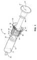
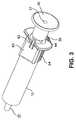
- FIG. 5is a perspective view showing of a syringe according to another exemplary embodiment of the present invention.
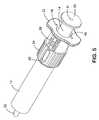
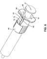
- FIG. 6is a perspective view showing the bottom of the syringe of FIG. 5 ;
- FIG. 7is a perspective view of the syringe of FIG. 5 with the collar locked in place;
- FIG. 8is an exploded partially transparent perspective view of the syringe of FIG. 5 ;
- FIG. 8Ais a cross sectional view of contents indicator sleeve 60 taken along line A-A;
- FIG. 8Bis a cross sectional view of contents indicator sleeve 60 taken along line B-B;
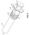
- FIG. 9is a perspective view showing a syringe according to another exemplary embodiment of the present invention.
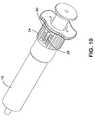
- FIG. 10is a perspective view of the syringe of FIG. 9 with the contents indicator collar locked in place;
- FIG. 11is a perspective view of a syringe according to another exemplary embodiment of the present invention with the contents indicator structure removed from the syringe barrel;
- FIG. 12is a perspective view of the syringe of FIG. 11 with the contents indicator collar disposed over the syringe barrel;
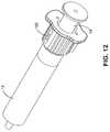
- FIG. 13is a perspective view of a syringe according to another exemplary embodiment of the present invention.
- FIG. 1is a partially transparent perspective view of a syringe 10 according to an exemplary embodiment of the invention.
- the three basic components of syringe 10are barrel 12 , plunger 14 and contents indicator collar 24 .
- portions of plunger 14 and internal features of barrel 12are visible in FIG. 1 , this does not necessarily mean that they would be visible in a physical embodiment of the syringe, i.e. structures of syringe 10 may be of a transparent material or of an opaque material.
- Plunger 14fits in the central bore 13 of barrel 12 .
- a sealing element 16is attached to the distal end portion 18 of plunger 14 . Sealing element 16 comes into sliding/sealing contact with the cylindrical inner wall of barrel 12 .
- the distal end of barrel 12 , the cylindrical inner wall of barrel 12 , and the sealing element 16 of plunger 14define the portion of central bore 13 capable of containing a liquid to be delivered by the syringe 10 .
- the size of the liquid containing portion of central bore 13may be varied by the sliding displacement of plunger 14 relative to barrel 12 .
- the liquid containing portion of central bore 13can be varied in size from nearly the entire volume of central bore 13 to zero or nearly zero volume.
- Syringe 10may contain a great variety of liquids.
- the liquid port 32may be put into contact with a liquid source; withdrawal of the plunger by way of handle 30 will cause a vacuum in central bore 13 , thus causing liquid to fill the liquid containing portion of central bore 13 through liquid port 32 .
- Liquidis prevented from entering the non-liquid containing portion of central bore 13 , i.e. proximal of distal end portion 18 , by the sealing contact between sealing element 16 of plunger 14 and the inner wall of barrel 12 .
- handle 30When it is desired to deliver the liquid contained in the liquid containing portion of syringe 10 , handle 30 is compressed distally, causing plunger 14 to move distally and reduce the size of the liquid containing portion of central bore 13 thus creating a pressure that causes the liquid to exit liquid port 32 .
- Finger wings 22are provided at the end of barrel 12 to allow a practitioner to accomplish this compression of handle 30 with a thumb and two fingers disposed distally of wings 22 in the standard syringe manner.
- the identity of the liquid contained in syringe 10is often difficult or impossible to determine accurately using sensory perception.
- the present inventionprovides a simple and accurate method of identifying the syringe contents. This identifying structure is both simple to use and requires a specific intent to change, such that alteration of this identification in an accidental manner is less likely.
- Contents indicator collar 24seen in FIGS. 1-4 , includes a collar window 26 .
- Collar 24may be rotated circumferentially about barrel 12 but is prevented from axial displacement by interaction between retention tab 42 and barrel flange 20 .
- multiple contents indicator designations 28may be printed on the external surface of barrel 12 . Each of these contents indicator designations 28 is sized to be easily readable through collar window 26 .
- Circumferential rotation of collar 24results in displacement of collar window 26 and registration thereof with a different contents indicator designation 28 .
- a practitionermay fill the liquid containing portion of central bore 13 with a particular liquid, as described previously, and identify the contents of syringe 10 by rotating collar 28 such that collar window 26 is in registration with the appropriate contents indicator designation 28 .
- a practitionermay identify the contents of syringe 10 by rotating collar 28 such that collar window 26 is in registration with the appropriate contents indicator designation 28 and then fill the liquid containing portion of central bore 13 with the designated liquid.
- Selection tab 34extends proximally from the proximal end of collar 24 .
- Selection tab 34extends into selection slot 36 which is formed in barrel flange 20 which extends axially from the proximal end of barrel 12 .
- Selection slot 36has disposed therein one or more selection cams 44 .
- Selection cams 44prevent circumferential movement of selection tab 34 in selection slot 36 absent a significant rotational force exerted on collar 24 . In the absence of a significant rotational force, selection tab 34 will not displace relative to selection slot 36 .
- collar 24 and collar window 26cannot be easily accidentally displaced with respect to barrel 12 .
- selection tab 34When a significant rotational force is exerted on collar 24 , selection tab 34 may be caused to deflect and slide over a selection cam 44 . Once selection tab 34 has passed over a selection cam 44 it resiliently deflects back to its original shape, again preventing collar 24 from circumferential rotation without significant rotational force being exerted. Placement of the selection cams 44 and the terminal ends of slot 36 are chosen such that an unstressed selection tab 34 position corresponds to collar window 26 being in registration with a single contents indicator designation 28 .
- Retention tab 42performs a dual role.
- the first role of retention tab 42is to prevent axial displacement of contents indicator collar 24 , as discussed previously.
- the barrel flange 20 and plunger 14may also be configured such that retention tab 42 prevents plunger 14 from being displaced proximally.
- Retention tab 42engages plunger flange 46 when retention tab 42 is aligned with cut-out 48 in barrel flange 20 , as shown in FIG. 3 .
- the retention tab 42 , plunger flange 46 , barrel flange 20 , and cut-out 48 structuresmay be used as a reminder to the practitioner to use the indicia mechanism of the present invention.
- examples of an appropriate contents indicator designation 28 when retention tab 42 is aligned with cut-out 48include no designation, i.e. contents indicator designation 28 is left blank, or the words “Choose Syringe Contents” or the like are used. Only upon rotation of collar 24 and selection of a contents indicator designation will barrel flange 20 deflect retention tab 42 such that retention tab 42 no longer engages plunger flange 46 .
- collar 24must be rotated before plunger 14 may be displaced proximally to fill syringe 10 with liquid. This requirement will increase the likelihood of the person filling the syringe first utilizing the contents indicia feature of the syringe of the present invention.
- one contents indicator designation 28may read “Turn Over” or similar language.
- the contents identification area 40is an area on the contents indicator collar 24 capable of receiving written or other indicia of syringe 10 contents. Contents identification area 40 may be capable of receiving ink from a pen or marker, or may be capable of having a sticker attached thereto. Contents identification area 40 may be used as a ‘miscellaneous’ indicator of syringe contents, i.e. where the syringe contents in not one of the available contents indicator designations 28 .
- Contents identification area 40may also be utilized in combination with an available contents indicator designation 28 to record, for example, the concentration of the solution contained in the syringe or the identity of the person who filled the syringe or the time when the syringe was filled.
- the use of stickers, preprinted or color coded, in conjunction with the contents identification area 40is an alternative to written information especially where the use of a pen is difficult or inadvisable.
- FIGS. 5-8An alternative embodiment of the present invention is shown in FIGS. 5-8 .
- This alternative embodimentseeks more positive and permanent locking of the contents indicator collar 24 once a contents indicator designation 28 has been chosen.
- FIG. 5illustrates the position of the contents indicator collar 24 when supplied to the medical professional, i.e. the collar 24 is disposed distally of the contents indicator designations 28 .
- the practitionerchooses a contents indicator designation 28 utilizing the collar window 26 .
- collar 24may be slid axially along the barrel 12 of syringe 10 in the proximal direction. Once the collar 24 abuts the finger wings 22 and barrel flange 20 , as seen in FIGS. 7 , the collar 24 is locked in place and the appropriate contents indicator designation 28 appears in collar window 26 .
- collar 24may not be moved, either axially or rotationally, once it is locked in place. This prevents inadvertent alteration of the contents indicator designation 28 .
- collar 24must be locked in place prior to filling the syringe 10 .
- a plurality of tab engagement grooves 74are provided on the inside surface of collar 24 . Each tab engagement groove 74 is indexed to a contents indicator designation 28 . As will be further discussed below, locking tab 72 enters into the tab engagement groove 74 indexed to the contents indicator designation 28 chosen by the person filling the syringe 10 .
- Contents indicator sleeve 60is disclosed in FIG. 8 and in two cross sections in FIGS. 8A and 8B .
- Contents indicator sleeve 60fits over barrel 12 and is retained on barrel 12 through any standard engagement method such as adhesive, welding, interference fit or the like.
- Tabs 82 and holes 78are utilized to assure proper alignment of indicator sleeve 60 and to assist in retention thereof on barrel 12 .
- Contents indicator sleeve 60also has an arm 64 .
- Arm 64has several tabs along its length.
- plunger flange engagement tab 66which extends through barrel flange notch 80 and engages plunger flange 46 and prevents withdrawal of plunger 14 from barrel 12 . That is, plunger flange engagement tab 66 in its unstressed position, shown in FIG. 8 , prevents filling of syringe 10 by engaging with plunger flange 46 and preventing movement of plunger 14 .
- Retention tab 70Adjacent the distal end of contents indicator sleeve 60 on the arm 64 is retention tab 70 .
- Retention tab 70retains collar 24 on contents indicator sleeve 60 , i.e. retention tab 70 prevents collar 24 from movement distally of the distal end of contents indicator sleeve 60 .
- Retention tab 70retains collar 24 by engaging a portion of tab engagement grooves 74 disposed on the inside surface of collar 24 .
- locking tab 72Between plunger flange engagement tab 66 and retention tab 70 on the arm 64 is locking tab 72 . Locking tab 72 locks collar 24 in place when the appropriate contents indicator designation has been chosen and the collar 24 has been moved proximally from the position shown in FIG. 5 to the position shown in FIG. 7 , as discussed previously.
- Locking tab 72interacts with tab engagement groove 74 on the inner surface of collar 24 .
- the engagement between locking tab 72 and tab engagement groove 74prevents any relative movement between collar 24 and contents indicator sleeve 60 , whether axial or rotational.
- collar 24is permanently locked into position once locking tab 72 engages tab engagement groove 74 .
- locking tab 72 and tab engagement groove 74Another function of locking tab 72 and tab engagement groove 74 is to cause the disengagement of plunger flange engagement tab 66 from plunger flange 46 and, thus, allow operation of the syringe 10 .
- locking tab 72is located between the ends of arm 64 .
- plunger flange engagement tabprevents withdrawal of plunger 14 though blocking plunger flange 46 .
- locking tab 72enters one of several available tab engagement grooves 74 , as shown in FIG. 6 .
- Each tab engagement groove 74is dimensioned such that a radial force is exerted on locking tab 72 as collar 24 is slid radially.
- the force on locking tab 72 and engagement of cantilever element 68 with the barrel 12causes plunger flange engagement tab 66 to flex away from the plunger. This flexing of plunger flange engagement tab 66 causes it to cease blocking plunger flange 46 , thus allowing displacement of plunger 14 with respect to barrel 12 .
- Tab engagement groove 74is dimensioned such that, even after locking tab 72 has locked collar 24 in position, a force remains on locking tab 72 such that plunger flange engagement tab 66 remains flexed away from plunger 14 such that it does not block plunger flange 46 .
- FIGS. 9 and 10show another exemplary embodiment of the present invention, in which collar 24 may be supplied with contents indicator designations 28 on the surface thereof.
- a contrasting background 90may be printed on the barrel 12 or on the contents indicator sleeve 60 .
- collar 24must be at least partially transparent.
- FIGS. 11 and 12Another exemplary embodiment of the present invention is disclosed in FIGS. 11 and 12 .
- a selection of preprinted contents indicator collars 100is provided.
- Each preprinted collar 100has an opening 102 allowing the preprinted collar 100 to be snapped over barrel 12 .
- This embodimentmay be used with either specialized syringes 10 or with generic syringes. Different sizes of preprinted collars, each size capable of being preprinted with a large assortment of contents indicators, may be sold to accommodate most syringe sizes.
- a bore 33may be formed along the entire length of plunger 14 . This bore 33 extents from an entrance point 31 , through the entire length of the plunger 31 , and then through distal end portion 18 and sliding element 16 of plunger 14 . This bore 33 may be used to feed a guidewire through the syringe 10 ; syringe 10 provides access to the patient for a guidewire (not shown).
- FIG. 13discloses an alternative structure for syringe 10 .
- Collar 24may also circumferentially engage plunger 14 .
- contents indicator designations 28are associated with the cylindrical surface adjacent the proximal end of plunger 14 .
- Collar 24engages plunger 14 in such a way that window 26 may be rotated to overlie one of contents indicator designations 28 .
- Selection slot 36is located in handle 30 of plunger 14 .
- Selection tab 34extends from the proximal end of collar 24 and engages selection cams 44 in selection slot 36 .
- the contents indicatortakes the form of any actuatable structural element that may be actuated from one position to another in order to select one of a plurality of contents indicator designations. Examples have been provided above but are not limiting. Other non-limiting examples include: (i) an axially sliding contents indicator that can be actuated to select one of a plurality of contents indicator designations; (ii) an arrow like contents indicator that can be actuated to select one of a plurality of contents indicator designations; and (iii) a set of actuatable shutters that can be actuated to obscure the non-selected contents indicator designations, leaving only the selected one of the plurality of contents indicators viewable.
Landscapes
- Health & Medical Sciences (AREA)
- Vascular Medicine (AREA)
- Engineering & Computer Science (AREA)
- Anesthesiology (AREA)
- Biomedical Technology (AREA)
- Heart & Thoracic Surgery (AREA)
- Hematology (AREA)
- Life Sciences & Earth Sciences (AREA)
- Animal Behavior & Ethology (AREA)
- General Health & Medical Sciences (AREA)
- Public Health (AREA)
- Veterinary Medicine (AREA)
- Infusion, Injection, And Reservoir Apparatuses (AREA)
Abstract
Description
Claims (24)
Priority Applications (6)
| Application Number | Priority Date | Filing Date | Title |
|---|---|---|---|
| US11/541,280US7976506B2 (en) | 2006-09-29 | 2006-09-29 | Syringe with selectable indicia of contents |
| ES07843347TES2425816T3 (en) | 2006-09-29 | 2007-09-27 | Syringe with selectable content signs |
| EP07843347.1AEP2066370B1 (en) | 2006-09-29 | 2007-09-27 | Syringe with selectable indicia of contents |
| CA2664811ACA2664811C (en) | 2006-09-29 | 2007-09-27 | Syringe with selectable indicia of contents |
| PCT/US2007/079703WO2008042701A2 (en) | 2006-09-29 | 2007-09-27 | Syringe with selectable indicia of contents |
| CNA2007101596479ACN101219248A (en) | 2006-09-29 | 2007-09-29 | Syringe with selectable indicia of contents |
Applications Claiming Priority (1)
| Application Number | Priority Date | Filing Date | Title |
|---|---|---|---|
| US11/541,280US7976506B2 (en) | 2006-09-29 | 2006-09-29 | Syringe with selectable indicia of contents |
Publications (2)
| Publication Number | Publication Date |
|---|---|
| US20080171995A1 US20080171995A1 (en) | 2008-07-17 |
| US7976506B2true US7976506B2 (en) | 2011-07-12 |
Family
ID=39269097
Family Applications (1)
| Application Number | Title | Priority Date | Filing Date |
|---|---|---|---|
| US11/541,280Expired - Fee RelatedUS7976506B2 (en) | 2006-09-29 | 2006-09-29 | Syringe with selectable indicia of contents |
Country Status (6)
| Country | Link |
|---|---|
| US (1) | US7976506B2 (en) |
| EP (1) | EP2066370B1 (en) |
| CN (1) | CN101219248A (en) |
| CA (1) | CA2664811C (en) |
| ES (1) | ES2425816T3 (en) |
| WO (1) | WO2008042701A2 (en) |
Cited By (7)
| Publication number | Priority date | Publication date | Assignee | Title |
|---|---|---|---|---|
| US20130016105A1 (en)* | 2009-12-02 | 2013-01-17 | Sanofi-Aventis Deutschland Gmbh | Dose display mechanism for a drug delivery device |
| US20140360894A1 (en)* | 2013-06-05 | 2014-12-11 | Ethel Marlene Miles | Carpule to Store Lower Dosage Amount of Dental Anesthetic |
| USD876620S1 (en)* | 2019-02-21 | 2020-02-25 | Stephen S Ho | Syringe |
| USD877894S1 (en)* | 2019-02-21 | 2020-03-10 | Stephen S Ho | Detachable plunger syringe |
| US10624615B2 (en) | 2017-10-06 | 2020-04-21 | Stephen S Ho | Apparatus and method for collecting and isolating cells |
| WO2021144621A1 (en) | 2020-01-14 | 2021-07-22 | Subul Alkhebrah Industrial Company | Integrated syringe and guidewire system |
| US20230048030A1 (en)* | 2020-01-27 | 2023-02-16 | Commscope Technologies Llc | Coding apparatuses and methods for a jumper cable for a cellular communications system |
Families Citing this family (42)
| Publication number | Priority date | Publication date | Assignee | Title |
|---|---|---|---|---|
| US7648483B2 (en) | 2004-11-22 | 2010-01-19 | Intelliject, Inc. | Devices, systems and methods for medicament delivery |
| US10737028B2 (en) | 2004-11-22 | 2020-08-11 | Kaleo, Inc. | Devices, systems and methods for medicament delivery |
| US11590286B2 (en) | 2004-11-22 | 2023-02-28 | Kaleo, Inc. | Devices, systems and methods for medicament delivery |
| US7947017B2 (en) | 2004-11-22 | 2011-05-24 | Intelliject, Inc. | Devices, systems and methods for medicament delivery |
| WO2006057636A1 (en) | 2004-11-22 | 2006-06-01 | Intelliject, Llc | Devices, systems, and methods for medicament delivery |
| AU2006210865B2 (en) | 2005-02-01 | 2008-12-04 | Kaleo, Inc. | Devices, systems, and methods for medicament delivery |
| US9022980B2 (en) | 2005-02-01 | 2015-05-05 | Kaleo, Inc. | Medical injector simulation device |
| US20080315046A1 (en)* | 2007-06-20 | 2008-12-25 | Shellie Greto | Kiosk, system and method for the pairing flowers and vases |
| USD639939S1 (en)* | 2008-03-04 | 2011-06-14 | Carmel Pharma Ab | Medical device |
| GB0819161D0 (en)* | 2008-10-18 | 2008-11-26 | Frontier Plastics Ltd | Improvements in and relating to injection syringes |
| CA2757054A1 (en)* | 2009-03-30 | 2010-10-07 | Sanofi-Aventis Deutschland Gmbh | Drug delivery device with integrated extendable /retractable information display element |
| DK2451507T3 (en)* | 2009-07-07 | 2018-04-30 | Sanofi Aventis Deutschland | PHARMACEUTICAL DISPENSER DEVICE WITH MECHANICAL DISPLAY TO BE ADJUSTED BY MOUNTING OF A PHARMACEUTICAL PATTERN |
| USD638538S1 (en)* | 2009-07-10 | 2011-05-24 | Becton, Dickinson And Company | Syringe plunger rod |
| US20120253288A1 (en)* | 2009-08-27 | 2012-10-04 | Sanofi-Aventis Deutschland Gmbh | Reminder device for drug delivery devices |
| JP5878124B2 (en)* | 2009-09-23 | 2016-03-08 | サノフィ−アベンティス・ドイチュラント・ゲゼルシャフト・ミット・ベシュレンクテル・ハフツング | Assembly for drug delivery device and drug delivery device |
| CA3042909C (en)* | 2010-06-18 | 2021-04-13 | Becton, Dickinson And Company | Adjustable dose setting plunger for syringe |
| US8939943B2 (en) | 2011-01-26 | 2015-01-27 | Kaleo, Inc. | Medicament delivery device for administration of opioid antagonists including formulations for naloxone |
| US9173999B2 (en) | 2011-01-26 | 2015-11-03 | Kaleo, Inc. | Devices and methods for delivering medicaments from a multi-chamber container |
| US8627816B2 (en) | 2011-02-28 | 2014-01-14 | Intelliject, Inc. | Medicament delivery device for administration of opioid antagonists including formulations for naloxone |
| US20140288506A1 (en)* | 2011-10-24 | 2014-09-25 | Owen Mumford Limited | Multi-dose syringe with a configurable scale |
| US9522235B2 (en) | 2012-05-22 | 2016-12-20 | Kaleo, Inc. | Devices and methods for delivering medicaments from a multi-chamber container |
| WO2016110561A1 (en)* | 2015-01-08 | 2016-07-14 | Novo Nordisk A/S | Drug injection device with visual end-of-contents indicator system |
| US10695495B2 (en) | 2015-03-24 | 2020-06-30 | Kaleo, Inc. | Devices and methods for delivering a lyophilized medicament |
| CA2990950A1 (en) | 2015-06-30 | 2017-01-05 | Kaleo, Inc. | Auto-injectors for administration of a medicament within a prefilled syringe |
| WO2018119218A1 (en) | 2016-12-23 | 2018-06-28 | Kaleo, Inc. | Medicament delivery device and methods for delivering drugs to infants and children |
| JP6936005B2 (en)* | 2016-12-26 | 2021-09-15 | HOYA Technosurgical株式会社 | Syringe and treatment set |
| US10857343B2 (en)* | 2017-04-06 | 2020-12-08 | Becton, Dickinson And Company | Medical devices with visual and tactile indicators |
| US11344715B2 (en) | 2018-01-26 | 2022-05-31 | Becton, Dickinson And Company | Flush syringe with disinfecting feature |
| US11083847B2 (en) | 2018-01-26 | 2021-08-10 | Becton, Dickinson And Company | Flush syringe with flip cap |
| US11273298B2 (en) | 2018-04-10 | 2022-03-15 | Becton, Dickinson And Company | Universal single-use cap for male and female connectors |
| US11844914B2 (en)* | 2018-06-05 | 2023-12-19 | Edwards Lifesciences Corporation | Removable volume indicator for syringe |
| US11229745B2 (en)* | 2019-05-03 | 2022-01-25 | Carefusion 303, Inc. | Syringe with priming indicator |
| CA3145580A1 (en) | 2019-08-09 | 2021-02-18 | Kaleo, Inc. | Devices and methods for delivery of substances within a prefilled syringe |
| US11975168B2 (en) | 2019-11-18 | 2024-05-07 | Becton, Dickinson And Company | Disinfectant cap |
| US11857753B2 (en) | 2019-12-23 | 2024-01-02 | Becton, Dickinson And Company | Disinfecting syringe tip |
| US11890445B2 (en) | 2019-12-23 | 2024-02-06 | Becton, Dickinson And Company | Universal disinfection cap |
| US12029828B2 (en) | 2020-03-05 | 2024-07-09 | Becton, Dickinson And Company | Disinfection cap |
| US12005223B2 (en) | 2020-04-17 | 2024-06-11 | Becton, Dickinson And Company | Disinfection cap |
| US12383719B2 (en) | 2020-04-17 | 2025-08-12 | Becton, Dickinson And Company | Disinfecting cap with re-use prevention |
| US11890446B2 (en) | 2020-04-17 | 2024-02-06 | Becton, Dickinson And Company | Cap for male and female threaded fittings |
| US11969572B2 (en) | 2020-04-17 | 2024-04-30 | Becton, Dickinson And Company | Disinfection cap |
| US12268847B1 (en) | 2021-02-10 | 2025-04-08 | Kaleo, Inc. | Devices and methods for delivery of substances within a medicament container |
Citations (19)
| Publication number | Priority date | Publication date | Assignee | Title |
|---|---|---|---|---|
| US2283915A (en) | 1938-12-01 | 1942-05-26 | Samuel F Cole | Syringe |
| US3232117A (en) | 1962-09-14 | 1966-02-01 | Roger Gilmont Instr Inc | Micrometer buret |
| US3391694A (en) | 1965-09-07 | 1968-07-09 | Pharmaseal Lab | Hypodermic syringe with identification cardholder |
| US3815785A (en) | 1972-12-04 | 1974-06-11 | Gilmont R Instr Inc | Micrometric dispenser with calibration means |
| US3885562A (en)* | 1973-11-16 | 1975-05-27 | John C Lampkin | Syringe with writing surface |
| US4056096A (en) | 1976-03-19 | 1977-11-01 | Medi-Ray, Inc. | Shielded syringe |
| US4178071A (en) | 1977-10-26 | 1979-12-11 | Asbell Burma B | Magnifying cylinder for insulin syringe |
| US4743234A (en) | 1987-05-18 | 1988-05-10 | The Cloverline, Inc. | Syringe magnifier |
| US5489275A (en)* | 1994-11-14 | 1996-02-06 | Ep Technologies, Inc. | Identification ring for catheter |
| US5498243A (en) | 1995-01-31 | 1996-03-12 | Unique Management Enterprises, Inc. | Apparatus for shielding a syringe needle |
| US6042562A (en) | 1997-10-30 | 2000-03-28 | Medicorp Endovascular Technologies, Inc. | Handle for a catheter |
| US6120481A (en) | 1998-12-21 | 2000-09-19 | Becton, Dickinson And Company | Scale on a plastic syringe |
| US6315760B1 (en) | 2000-05-09 | 2001-11-13 | Inviro Medical Devices Ltd. | Syringe with a background for writing and reading index markings |
| US6338200B1 (en) | 1999-10-08 | 2002-01-15 | Baxa Corporation | Syringe dose identification system |
| US6420657B1 (en) | 2001-01-16 | 2002-07-16 | Dell Products L.P. | Cable identification system and method |
| US20030050609A1 (en) | 2000-03-24 | 2003-03-13 | Bernard Sams | One-way clutch mechanisms and injector devices |
| US6699223B2 (en) | 2001-04-26 | 2004-03-02 | Invrio Medical Devices Ltd. | Safety syringe with releasable anti-rotation retractable needle adapter |
| US20040186437A1 (en) | 2003-03-20 | 2004-09-23 | Frenette Claude E. | Content-coded medical syringe, syringe set and syringe content identification method |
| US6821266B2 (en)* | 2002-11-12 | 2004-11-23 | U.S. Technology, Inc. | Syringe |
Family Cites Families (1)
| Publication number | Priority date | Publication date | Assignee | Title |
|---|---|---|---|---|
| US5645534A (en)* | 1994-06-24 | 1997-07-08 | Becton Dickinson And Company | Time of last injection indicator for medication delivery pen |
- 2006
- 2006-09-29USUS11/541,280patent/US7976506B2/ennot_activeExpired - Fee Related
- 2007
- 2007-09-27WOPCT/US2007/079703patent/WO2008042701A2/enactiveApplication Filing
- 2007-09-27CACA2664811Apatent/CA2664811C/ennot_activeExpired - Fee Related
- 2007-09-27EPEP07843347.1Apatent/EP2066370B1/ennot_activeNot-in-force
- 2007-09-27ESES07843347Tpatent/ES2425816T3/enactiveActive
- 2007-09-29CNCNA2007101596479Apatent/CN101219248A/enactivePending
Patent Citations (19)
| Publication number | Priority date | Publication date | Assignee | Title |
|---|---|---|---|---|
| US2283915A (en) | 1938-12-01 | 1942-05-26 | Samuel F Cole | Syringe |
| US3232117A (en) | 1962-09-14 | 1966-02-01 | Roger Gilmont Instr Inc | Micrometer buret |
| US3391694A (en) | 1965-09-07 | 1968-07-09 | Pharmaseal Lab | Hypodermic syringe with identification cardholder |
| US3815785A (en) | 1972-12-04 | 1974-06-11 | Gilmont R Instr Inc | Micrometric dispenser with calibration means |
| US3885562A (en)* | 1973-11-16 | 1975-05-27 | John C Lampkin | Syringe with writing surface |
| US4056096A (en) | 1976-03-19 | 1977-11-01 | Medi-Ray, Inc. | Shielded syringe |
| US4178071A (en) | 1977-10-26 | 1979-12-11 | Asbell Burma B | Magnifying cylinder for insulin syringe |
| US4743234A (en) | 1987-05-18 | 1988-05-10 | The Cloverline, Inc. | Syringe magnifier |
| US5489275A (en)* | 1994-11-14 | 1996-02-06 | Ep Technologies, Inc. | Identification ring for catheter |
| US5498243A (en) | 1995-01-31 | 1996-03-12 | Unique Management Enterprises, Inc. | Apparatus for shielding a syringe needle |
| US6042562A (en) | 1997-10-30 | 2000-03-28 | Medicorp Endovascular Technologies, Inc. | Handle for a catheter |
| US6120481A (en) | 1998-12-21 | 2000-09-19 | Becton, Dickinson And Company | Scale on a plastic syringe |
| US6338200B1 (en) | 1999-10-08 | 2002-01-15 | Baxa Corporation | Syringe dose identification system |
| US20030050609A1 (en) | 2000-03-24 | 2003-03-13 | Bernard Sams | One-way clutch mechanisms and injector devices |
| US6315760B1 (en) | 2000-05-09 | 2001-11-13 | Inviro Medical Devices Ltd. | Syringe with a background for writing and reading index markings |
| US6420657B1 (en) | 2001-01-16 | 2002-07-16 | Dell Products L.P. | Cable identification system and method |
| US6699223B2 (en) | 2001-04-26 | 2004-03-02 | Invrio Medical Devices Ltd. | Safety syringe with releasable anti-rotation retractable needle adapter |
| US6821266B2 (en)* | 2002-11-12 | 2004-11-23 | U.S. Technology, Inc. | Syringe |
| US20040186437A1 (en) | 2003-03-20 | 2004-09-23 | Frenette Claude E. | Content-coded medical syringe, syringe set and syringe content identification method |
Non-Patent Citations (2)
| Title |
|---|
| PCT/US07/079703SR, Sep. 27, 2007, Arrow International, Inc. |
| PCT/US07/079703WO, Sep. 27, 2007, Arrow International, Inc. |
Cited By (9)
| Publication number | Priority date | Publication date | Assignee | Title |
|---|---|---|---|---|
| US20130016105A1 (en)* | 2009-12-02 | 2013-01-17 | Sanofi-Aventis Deutschland Gmbh | Dose display mechanism for a drug delivery device |
| US9463284B2 (en)* | 2009-12-02 | 2016-10-11 | Sanofi-Aventis Deutschland Gmbh | Dose display mechanism for drug delivery device with first and second windows and scales |
| US20140360894A1 (en)* | 2013-06-05 | 2014-12-11 | Ethel Marlene Miles | Carpule to Store Lower Dosage Amount of Dental Anesthetic |
| US10624615B2 (en) | 2017-10-06 | 2020-04-21 | Stephen S Ho | Apparatus and method for collecting and isolating cells |
| USD876620S1 (en)* | 2019-02-21 | 2020-02-25 | Stephen S Ho | Syringe |
| USD877894S1 (en)* | 2019-02-21 | 2020-03-10 | Stephen S Ho | Detachable plunger syringe |
| WO2021144621A1 (en) | 2020-01-14 | 2021-07-22 | Subul Alkhebrah Industrial Company | Integrated syringe and guidewire system |
| EP4090401A4 (en)* | 2020-01-14 | 2024-01-24 | Alsahab Medical Company | Integrated syringe and guidewire system |
| US20230048030A1 (en)* | 2020-01-27 | 2023-02-16 | Commscope Technologies Llc | Coding apparatuses and methods for a jumper cable for a cellular communications system |
Also Published As
| Publication number | Publication date |
|---|---|
| WO2008042701A2 (en) | 2008-04-10 |
| EP2066370A4 (en) | 2012-07-25 |
| WO2008042701A3 (en) | 2008-07-10 |
| EP2066370A2 (en) | 2009-06-10 |
| US20080171995A1 (en) | 2008-07-17 |
| CA2664811A1 (en) | 2008-04-10 |
| CN101219248A (en) | 2008-07-16 |
| CA2664811C (en) | 2014-10-21 |
| EP2066370B1 (en) | 2013-07-03 |
| ES2425816T3 (en) | 2013-10-17 |
Similar Documents
| Publication | Publication Date | Title |
|---|---|---|
| US7976506B2 (en) | Syringe with selectable indicia of contents | |
| CA2494314C (en) | Color-coded medical dosing container | |
| US5961495A (en) | Medication delivery pen having a priming mechanism | |
| US5271527A (en) | Reusable pharmaceutical dispenser with full stroke indicator | |
| US20110015576A1 (en) | Medicament identification system for multi-dose injection devices | |
| JP5222353B2 (en) | Method of administering a liquid reactive substance from a multi-chamber ampoule | |
| ES2740550T3 (en) | Self-injection device with indicator to indicate the proper connection of components | |
| US20060084925A1 (en) | Medical syringe with colored plunger and transparent barrel assembly | |
| US20080269688A1 (en) | Dose Indicating Assembly of a Pharmaceutical Injection Device | |
| US20070142786A1 (en) | System with color-coded medical syringes and basins | |
| US20050113764A1 (en) | Insulin syringe with magnified sheath | |
| PT1832305E (en) | Medicament cartridge having identification means | |
| US20070088285A1 (en) | Syringe marking template | |
| US11007123B2 (en) | Enteral safety system and methods | |
| JP6203517B2 (en) | Prefilled syringe | |
| CA2202757C (en) | Identification ring for catheter | |
| GB2599444A (en) | Syringe device | |
| WO2003063936A1 (en) | Set consisting of syringe for injections and magazine containing the needles | |
| WO2006031227A1 (en) | Drug delivery warning system |
Legal Events
| Date | Code | Title | Description |
|---|---|---|---|
| AS | Assignment | Owner name:ARROW INTERNATIONAL, INC., PENNSYLVANIA Free format text:ASSIGNMENT OF ASSIGNORS INTEREST;ASSIGNORS:VITULLO, JEFFREY M.;MOORE, MATTHEW J.;HARDING, RICHARD L.;REEL/FRAME:018649/0327 Effective date:20061130 | |
| STCF | Information on status: patent grant | Free format text:PATENTED CASE | |
| FPAY | Fee payment | Year of fee payment:4 | |
| SULP | Surcharge for late payment | ||
| AS | Assignment | Owner name:JPMORGAN CHASE BANK, N.A., AS ADMINISTRATIVE AGENT, ILLINOIS Free format text:SECURITY INTEREST;ASSIGNOR:ARROW INTERNATIONAL, INC.;REEL/FRAME:041759/0160 Effective date:20170217 Owner name:JPMORGAN CHASE BANK, N.A., AS ADMINISTRATIVE AGENT Free format text:SECURITY INTEREST;ASSIGNOR:ARROW INTERNATIONAL, INC.;REEL/FRAME:041759/0160 Effective date:20170217 | |
| MAFP | Maintenance fee payment | Free format text:PAYMENT OF MAINTENANCE FEE, 8TH YEAR, LARGE ENTITY (ORIGINAL EVENT CODE: M1552); ENTITY STATUS OF PATENT OWNER: LARGE ENTITY Year of fee payment:8 | |
| AS | Assignment | Owner name:JPMORGAN CHASE BANK, N.A., AS ADMINISTRATIVE AGENT Free format text:SECURITY INTEREST;ASSIGNOR:ARROW INTERNATIONAL, INC.;REEL/FRAME:050619/0681 Effective date:20190925 | |
| AS | Assignment | Owner name:ARROW INTERNATIONAL LLC, NORTH CAROLINA Free format text:CONVERSION AND CHANGE OF NAME;ASSIGNOR:ARROW INTERNATIONAL, INC.;REEL/FRAME:053754/0731 Effective date:20200330 | |
| AS | Assignment | Owner name:TELEFLEX LIFE SCIENCES LIMITED, MALTA Free format text:ASSIGNMENT OF ASSIGNORS INTEREST;ASSIGNOR:ARROW INTERNATIONAL LLC;REEL/FRAME:058917/0270 Effective date:20211210 | |
| FEPP | Fee payment procedure | Free format text:MAINTENANCE FEE REMINDER MAILED (ORIGINAL EVENT CODE: REM.); ENTITY STATUS OF PATENT OWNER: LARGE ENTITY | |
| LAPS | Lapse for failure to pay maintenance fees | Free format text:PATENT EXPIRED FOR FAILURE TO PAY MAINTENANCE FEES (ORIGINAL EVENT CODE: EXP.); ENTITY STATUS OF PATENT OWNER: LARGE ENTITY | |
| STCH | Information on status: patent discontinuation | Free format text:PATENT EXPIRED DUE TO NONPAYMENT OF MAINTENANCE FEES UNDER 37 CFR 1.362 | |
| FP | Lapsed due to failure to pay maintenance fee | Effective date:20230712 |