US7976462B2 - Endoscope designs and methods of manufacture - Google Patents
Endoscope designs and methods of manufactureDownload PDFInfo
- Publication number
- US7976462B2 US7976462B2US11/099,435US9943505AUS7976462B2US 7976462 B2US7976462 B2US 7976462B2US 9943505 AUS9943505 AUS 9943505AUS 7976462 B2US7976462 B2US 7976462B2
- Authority
- US
- United States
- Prior art keywords
- endoscope
- end portion
- distal end
- longitudinal member
- optical path
- Prior art date
- Legal status (The legal status is an assumption and is not a legal conclusion. Google has not performed a legal analysis and makes no representation as to the accuracy of the status listed.)
- Expired - Fee Related, expires
Links
Images


Classifications
- A—HUMAN NECESSITIES
- A61—MEDICAL OR VETERINARY SCIENCE; HYGIENE
- A61B—DIAGNOSIS; SURGERY; IDENTIFICATION
- A61B1/00—Instruments for performing medical examinations of the interior of cavities or tubes of the body by visual or photographical inspection, e.g. endoscopes; Illuminating arrangements therefor
- A61B1/00064—Constructional details of the endoscope body
- A61B1/00071—Insertion part of the endoscope body
- A61B1/0008—Insertion part of the endoscope body characterised by distal tip features
- A61B1/00096—Optical elements
- A—HUMAN NECESSITIES
- A61—MEDICAL OR VETERINARY SCIENCE; HYGIENE
- A61B—DIAGNOSIS; SURGERY; IDENTIFICATION
- A61B1/00—Instruments for performing medical examinations of the interior of cavities or tubes of the body by visual or photographical inspection, e.g. endoscopes; Illuminating arrangements therefor
- A61B1/04—Instruments for performing medical examinations of the interior of cavities or tubes of the body by visual or photographical inspection, e.g. endoscopes; Illuminating arrangements therefor combined with photographic or television appliances
- A61B1/042—Instruments for performing medical examinations of the interior of cavities or tubes of the body by visual or photographical inspection, e.g. endoscopes; Illuminating arrangements therefor combined with photographic or television appliances characterised by a proximal camera, e.g. a CCD camera
- A—HUMAN NECESSITIES
- A61—MEDICAL OR VETERINARY SCIENCE; HYGIENE
- A61B—DIAGNOSIS; SURGERY; IDENTIFICATION
- A61B1/00—Instruments for performing medical examinations of the interior of cavities or tubes of the body by visual or photographical inspection, e.g. endoscopes; Illuminating arrangements therefor
- A61B1/04—Instruments for performing medical examinations of the interior of cavities or tubes of the body by visual or photographical inspection, e.g. endoscopes; Illuminating arrangements therefor combined with photographic or television appliances
- A61B1/055—Instruments for performing medical examinations of the interior of cavities or tubes of the body by visual or photographical inspection, e.g. endoscopes; Illuminating arrangements therefor combined with photographic or television appliances having rod-lens arrangements
- A—HUMAN NECESSITIES
- A61—MEDICAL OR VETERINARY SCIENCE; HYGIENE
- A61B—DIAGNOSIS; SURGERY; IDENTIFICATION
- A61B1/00—Instruments for performing medical examinations of the interior of cavities or tubes of the body by visual or photographical inspection, e.g. endoscopes; Illuminating arrangements therefor
- A61B1/06—Instruments for performing medical examinations of the interior of cavities or tubes of the body by visual or photographical inspection, e.g. endoscopes; Illuminating arrangements therefor with illuminating arrangements
- A61B1/0661—Endoscope light sources
- A61B1/0676—Endoscope light sources at distal tip of an endoscope
- A—HUMAN NECESSITIES
- A61—MEDICAL OR VETERINARY SCIENCE; HYGIENE
- A61B—DIAGNOSIS; SURGERY; IDENTIFICATION
- A61B1/00—Instruments for performing medical examinations of the interior of cavities or tubes of the body by visual or photographical inspection, e.g. endoscopes; Illuminating arrangements therefor
- A61B1/06—Instruments for performing medical examinations of the interior of cavities or tubes of the body by visual or photographical inspection, e.g. endoscopes; Illuminating arrangements therefor with illuminating arrangements
- A61B1/0661—Endoscope light sources
- A61B1/0684—Endoscope light sources using light emitting diodes [LED]
- A—HUMAN NECESSITIES
- A61—MEDICAL OR VETERINARY SCIENCE; HYGIENE
- A61B—DIAGNOSIS; SURGERY; IDENTIFICATION
- A61B1/00—Instruments for performing medical examinations of the interior of cavities or tubes of the body by visual or photographical inspection, e.g. endoscopes; Illuminating arrangements therefor
- A61B1/06—Instruments for performing medical examinations of the interior of cavities or tubes of the body by visual or photographical inspection, e.g. endoscopes; Illuminating arrangements therefor with illuminating arrangements
- A61B1/07—Instruments for performing medical examinations of the interior of cavities or tubes of the body by visual or photographical inspection, e.g. endoscopes; Illuminating arrangements therefor with illuminating arrangements using light-conductive means, e.g. optical fibres
- A—HUMAN NECESSITIES
- A61—MEDICAL OR VETERINARY SCIENCE; HYGIENE
- A61B—DIAGNOSIS; SURGERY; IDENTIFICATION
- A61B1/00—Instruments for performing medical examinations of the interior of cavities or tubes of the body by visual or photographical inspection, e.g. endoscopes; Illuminating arrangements therefor
- A61B1/313—Instruments for performing medical examinations of the interior of cavities or tubes of the body by visual or photographical inspection, e.g. endoscopes; Illuminating arrangements therefor for introducing through surgical openings, e.g. laparoscopes
- A61B1/3137—Instruments for performing medical examinations of the interior of cavities or tubes of the body by visual or photographical inspection, e.g. endoscopes; Illuminating arrangements therefor for introducing through surgical openings, e.g. laparoscopes for examination of the interior of blood vessels
- A—HUMAN NECESSITIES
- A61—MEDICAL OR VETERINARY SCIENCE; HYGIENE
- A61B—DIAGNOSIS; SURGERY; IDENTIFICATION
- A61B1/00—Instruments for performing medical examinations of the interior of cavities or tubes of the body by visual or photographical inspection, e.g. endoscopes; Illuminating arrangements therefor
- A61B1/00163—Optical arrangements
- A61B1/00174—Optical arrangements characterised by the viewing angles
- A61B1/00179—Optical arrangements characterised by the viewing angles for off-axis viewing
Definitions
- the present inventionrelates generally to optical systems, and in some embodiments, those suitable for endoscopes and other medical devices.
- Endoscopesgenerally include a catheter with imaging optics to be inserted into a patient. Illumination may be provided by a source that is located external to the patient. Light from the illumination source may travel via a conduit, such as a fiberoptic or fiberoptic bundle, through the catheter into the patient. The light may be emitted inside of the patient at the catheter's distal end near a treatment or viewing site. Features inside the body are likewise illuminated and can be viewed using the imaging optics, which form images of the patient's insides.
- an endoscopehas proximal and distal end portions for viewing inside a cavity of a body.
- the endoscopecomprises: one or more solid state emitters having an electrical input and an optical output, said one or more solid state emitters disposed at said distal end portion of said endoscope, said one or more solid state emitters radiating light when activated so as to illuminate at least a portion of said cavity in said body; an optical path extending from said distal end portion to said proximal end portion for propagating light from said distal end portion to said proximal end portion of said endoscope such that an image of an object at said distal end portion can be formed at said proximal end portion; and an electrically conducting path from said proximal end portion to said distal end portion of said endoscope, said electrically conducting path electrically connected to said electrical input of said one or more solid state emitters for providing electrical power to said one or more solid state emitters.
- an endoscopehas proximal and distal end portions for viewing features inside a body into which said distal end portion of said endoscope is inserted.
- the endoscopecomprises: a longitudinal member extending from said distal end portion to said proximal end portion, said longitudinal member having an inner cavity region; an optical path through said inner cavity region of said longitudinal member for propagating light from said distal end portion to said proximal end portion of said endoscope; and a first specularly reflective metalized non-glass surface disposed along said optical path at said distal end portion of said longitudinal member, said first specularly reflective metalized surface angled such that light can be collected at said distal end portion from an oblique direction with respect of said longitudinal member.
- a battery operated hand-held endoscope instrumenthas proximal and distal end portions for producing images of internal regions of a body.
- the endoscope instrumentcomprises: one or more solid state emitters having an electrical input and an optical output, said one or more solid state emitters disposed at said distal end portion of said endoscope instrument, said one or more solid state emitters for illuminating said internal regions of said body; an optical path extending from said distal end portion to said proximal end portion for propagating light from said distal end portion to said proximal end portion of said endoscope instrument to form an image at said proximal end portion; an electrically conducting path from said proximal end portion to said distal end portion of said endoscope, said electrically conducting path electrically connected to said electrical input of said one or more solid state emitters for providing electrical power from a battery at said proximal end portion to said one or more solid state emitters at said distal end portion; an optical sensor disposed at said proximal end portion of said endoscope
- a endoscopehas proximal and distal ends for viewing features inside a body.
- the endoscopecomprises: a plurality of rod lenses aligned along an optical path; a slotted elongate support structure comprising a plurality of slots in which said plurality of rod lenses respectively fit so as to be aligned along said optical path; and an outer tube with a hollow inner region, said elongated support structure together with said plurality of rod lens disposed in said hollow inner region of said out tube, wherein said slots are separated with respect to each other so as to establish suitable spacing between said lenses to relay an image of a feature in said body to said proximal end portion.
- a method of manufacturing an endoscope assembly for viewing portions of a bodycomprises: providing an elongated support structure having a plurality of sites for insertion of optical elements; inserting a plurality of lenses at said sites; inserting said elongated support structure into a hollow outer protective shield having an open inner region, wherein said plurality of sites are laterally positioned and longitudinally spaced from with respect to each other so as to provide an aligned optical system that relays an image from said distal end portion to said proximal end portion.
- a method of manufacturing a front end of an endoscope for viewing portions of a bodycomprises: forming a front endpiece, said front endpiece for receiving light from said body portions to enable viewing of said body portions; forming an inner cavity region in said front endpiece, said inner cavity region for passage of said light from said body portions; forming at least one substantially planar sidewall surface in said inner cavity region; and metalizing said at least one substantially planar sidewall surface so as to form a substantially reflective surface that reflects said light received from said body portions.
- a head for an endoscope for viewing objectscomprises: a main body having a front and a rear, said front to be disposed with respect to said object such that light from said object propagates toward said front of said main body; an inner open region in said main body, light from said object propagating into said inner open region, said inner open region defined by interior sidewalls of said main body; and apertures at said front and rear of said main body providing access to said inner open region, wherein at least one of said sidewalls is coated with a substantially reflective material and is substantially smooth so as to form a substantially reflective surface, said reflective surface reflecting light from said object such that an image of said object can be formed.
- a disposable endoscope for viewing features inside a bodycomprises: a longitudinal member having distal and proximal ends and an inner cavity region therein, said longitudinal member further comprising an end portion at said distal end with an aperture therein for entry of light into said inner cavity, at least said end portion comprising plastic; one or more solid state emitters disposed at said distal end of said longitudinal member for providing illumination; and an optical path through said inner cavity region of said longitudinal member for propagating light from said distal end to said proximal end of said longitudinal member, said optical path including at least one optical element, wherein said end portion of said longitudinal member includes reflective material formed on said plastic in said end portion of said longitudinal member to reflect light received through said aperture along said optical path to said proximal end portion of said longitudinal member.
- a disposable endoscope for viewing features inside a bodycomprises: a longitudinal member having distal and proximal ends and an inner cavity region therein, said longitudinal member further comprising an end portion at said distal end with an aperture therein for entry of light into said inner cavity, at least said end portion comprising ceramic material; one or more solid state emitters disposed at said distal end of said longitudinal member for providing illumination; and an optical path through said inner cavity region of said longitudinal member for propagating light from said distal end to said proximal end of said longitudinal member, said optical path including at least one optical element, wherein said end portion of said longitudinal member includes reflective material formed on said ceramic material in said end portion of said longitudinal member to reflect light received through said aperture along said optical path to said proximal end portion of said longitudinal member.
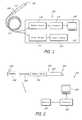
- FIG. 1illustrates one system for producing images of features inside of body parts
- FIG. 2illustrates another system for producing images of features inside of body parts
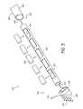
- FIG. 3is an exploded perspective view of a longitudinal member
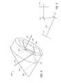
- FIG. 4is a rear perspective view of an exemplary front lens holder that may be used with the longitudinal member of FIG. 3 ;
- FIG. 5shows a schematic diagram of an optical path through a front surface tilted at an angle with respect to a rear surface
- FIG. 6shows another view of a front lens holder for used with a longitudinal member, such as the longitudinal member of FIG. 3 ;
- FIG. 7is a perspective view of an elongated support structure, which may be used as the cradle of FIG. 3 ;
- FIG. 8is a partial perspective view of an exemplary slotted elongate support structure, which may also be used as the cradle of FIG. 3 .
- Embodiments of the present inventioncomprise endoscopes for viewing inside a cavity of a body such as a vessel like a vein or artery or elsewhere.
- the endoscopeshave a light source that is configured, sized and positioned so as to be inserted into the body cavity to provide illumination therein.
- this light sourcecomprises at least one solid state emitter such as a light emitting diode (LED).
- LEDlight emitting diode
- this solid state emitteris small and bright.
- Light emitted from the light sourceis reflected off objects or walls in the interior of the body cavity. A portion of the reflected light is collected through an aperture in the endoscope. This light is directed along an optical path through the endoscope so as to form an image of the objects or walls.
- the optical pathincludes a series of lenses such as rod lenses disposed in a support structure or cradle.
- the lightis then directed to an optical sensor such as, for example, an optical detector array or an optical camera.
- an optical sensorsuch as, for example, an optical detector array or an optical camera.
- FIG. 1illustrates one system 100 according to an embodiment of the invention for producing images such as electronic, e.g., video or digital, images of features inside, for example, body parts.
- the system 100includes an endoscope structure 110 coupled to an imaging and control apparatus 114 through a cable 112 .
- the imaging and control apparatus 114includes an optical sensor 116 , a processor 118 , a display 120 , a power supply 122 , and a power control 124 .
- the endoscope structure 110comprises an elongated member that is inserted into a portion of a body such as a human body.
- This endoscope structure 110includes a distal end portion 126 and a proximal end portion 128 .
- One or more solid state emittersare preferably disposed at the distal end portion 126 .
- the solid state emitterseach include an electrical input and have an optical output.
- the solid state emittersmay comprise, for example, light emitting diodes (LEDs).
- LEDslight emitting diodes
- these solid state emittersare bright and small. In some embodiments, for example, these solid state emitters radiate over 10 lumens. These LED may be less than a millimeter and in some embodiments may be about 0.5 millimeters.
- a plurality of such small solid state emittersmay be disposed at the distal end of the endoscope structure 110 . In certain embodiments 2, 3, 4, 5, 6, 7, 8, or more emitters are employed. In some embodiments, these emitters emit white light although emitters need not be white light emitters. Colored emitters and emitters that radiate in narrow wavelength ranges may be employed as well. For example, images may be formed by optical sensors 116 that are sensitive to the particular wavelength region used for illumination. In certain embodiments, a specific wavelength illumination may be employed for fluorescence applications.
- the solid state emittersradiate light and illuminate a portion of a body cavity.
- the distal end 126 of the endoscope structure 110includes an aperture (not shown) for collecting light reflected or scattered from the illuminated portion of the body cavity.
- the light collected through the apertureis transferred along an optical path (not shown) from the distal end 126 of the endoscope structure 110 to the proximal end 128 .
- features in the illuminated portion of the cavityare imaged and the image is relayed along the optical path so as to form an image of a portion of the body cavity at the proximal end 128 .
- the cablepreferably comprises a system of relay lens or a coherent fiber bundle.
- the cablepreferably transfers the image to the optical sensor 116 in the imaging apparatus 114 .
- the optical sensor 116which may comprise a detector array such as a CCD or CMOS sensor array, has a light sensitive optical input that receives the light from the cable 112 .
- the optical sensor 116preferably further comprises an electrical signal output for outputting an electrical signal corresponding to the image of the illuminated portion of the body cavity.
- the electrical signal from the optical sensor 116is transmitted to a processor 118 and onto a on the display device 120 such as a video screen or computer monitor.
- a processor 118may transmitting the electrical signal from the optical sensor 116 directly to the display device 120 , for example, when the optical sensor 116 performs the processing.
- the cable 112comprises a fiber optic such as a coherent fiber optic bundle.
- the cable 112also preferably includes electrical power lines (not shown), such as thin electrical leads or wires, that provide electrical power to the solid state emitters disposed at the distal end 126 of the endoscope 110 .
- the electrical power linesare electrically coupled to the power supply 122 .
- This power supply 122may, for example, provide 12 or 24 volts and 20 milliamps to 1.5 Amp of current, however, voltages and currents outside these ranges are possible.
- the power supply 122may be controlled by the power controller 124 .
- the power controller 124may, for example, enable the current supplied to the solid state emitters at the distal end 126 of the endoscope structure 110 to be adjusted. Accordingly, the brightness or intensity of the light emitted from the solid state emitters can be adjusted.
- the power controlcomprises a rheostat.
- the cable 112is included in the endoscope system 100 shown in FIG. 1 , this cable is not required. In other embodiment, this cable 112 may be excluded.
- the optical sensor 116may be disposed at the proximal end portion 128 of the endoscope structure 110 . In such designs, electrical cable may be connected to the endoscope structure 110 to power the one or more solid state emitters at the distal end portion 126 .
- the endoscope structure 110is disposable. Various design features discussed more fully below may reduce the cost of the endoscope structures 110 such that the endoscope structure need not be reused over and over but may be discarded after use. In some embodiments, the endoscope structure 110 may plug into the cable 112 and thus may be detached and disposed of and replaced for the next procedure.
- FIG. 2illustrates a system 200 that offers increased ease of use.
- the system 200includes an endoscope structure 220 , a receiver 222 , a processor 224 , and a display device 226 .
- the endoscope shown in FIG. 2is a battery operated, hand-held instrument which is configured to produce images of internal regions of a body as described above.
- the endoscope structure 220 shownincludes a distal end 230 and a proximal end 232 and one or more solid state emitters (not shown) at the distal end that emit light to illuminate internal regions of the body.
- the distal end 230 of the endoscope structure 220further includes an aperture (not shown) for collecting light emitted from the solid state emitters and reflected off of the internal regions of the body.
- An optical path (not shown)extends from the distal end 230 of the endoscope structure 220 to a proximal end 232 .
- the optical sensor 234is disposed to receive collected light and more particularly, an image of a portion of the body, and to provide an electrical signal output.
- the light collected at the distal end 230forms an image on the optical sensor 234 which produces an electrical output corresponding to the image of the illuminated internal region of the body.
- the electrical signalis supplied to the transmitter 236 , which transmits the signal to the receiver 222 .
- the transmitter 236 and the receiver 222are preferably wireless.
- the transmitter 236comprises an RF transmitter and the receiver 222 comprises an RF receiver.
- the receiver 222provides the received signal to the processor 224 that feeds signals to the display device 226 .
- the processor 224may format the received signal so that the image of the illuminated internal region of the body can be displayed. This processor 224 may also provide additional image processing.
- the optical sensor 234provides the necessary formatting and processing and the received signal is transferred directly from the receiver 222 to the display device 226 . Other distributions of functions between electronics in the optical sensor 234 and processor 224 are possible.
- the battery 238is electrically coupled to the transmitter 236 , the optical sensor 234 and to the solid state emitters disposed at the distal end 230 of the endoscope structure 220 .
- the control device 240may be configured to allow a user of the endoscope to control the amount of current supplied by the battery 238 to the solid state emitters disposed at the distal end 230 of the endoscope structure 220 .
- the control device 240is also configured to allow the user to selectively apply or remove a power signal from the battery 238 to the transmitter 236 and solid state emitters.
- This controller device 240may comprise, for example, a rheostat or potentiometer, or digital switch, in certain embodiments.
- the control devicemay comprise a integrated circuit chip, such as a microprocessor, in certain embodiments.
- the optical sensor 234 , transmitter 236 , and battery 238 disposed at the proximal end 232 of the endoscope structure 220allows the endoscope structure to be a self-contained instrument that is easily maneuverable and readily mobile.
- the endoscope structure 220does not need to be attached with wires or cables to provide power or to carry an image or signal to processing and display instruments. The user therefore has increased freedom to manipulate the endoscope structure and is not tethered to a console or power supply that would otherwise restrict the range of movement during a procedure.
- the endoscope structure 220is disposable.
- the endoscope structure 220including the solid state emitters, is disposable and is detachable from the optical sensor 234 , transmitter 236 , battery 238 , and control device 240 , which are reusable.
- Various design featureshelp reduce the cost of the endoscope structure 110 and enable disposal and replacement to be a competitive alternative to reuse.
- FIG. 3illustrates an exploded perspective view of a longitudinal member 300 comprising an endoscope structure, according to various embodiments of the invention.
- the longitudinal member 300has a distal end 320 and a proximal end 322 .
- the longitudinal member 300has a hollow inner cavity region 324 which provides an optical path from the distal end 320 to the proximal end 322 .
- a plurality of solid state emitters 326are disposed at the distal end 320 of the longitudinal member 300 .
- the solid state emitters 326each comprise an LED.
- the solid state emittersare configured to emit light into the body.
- the longitudinal member 300includes a front lens holder 328 having a front surface 332 with seats to receive the solid state emitters 326 .
- the front lens holder 328also includes a channel therethrough that comprises a portion of the inner cavity region 324 of the longitudinal member 300 .
- Front and rear apertures in the front lens holder 328provide access to the channel and a path through the lens holder 328 . Illumination reflected from portions of the body proceeds through this channel along this optical path.
- the front lens holder 328is configured to hold a front lens 330 that collects reflected light from the solid state emitters 326 into the inner cavity region 324 of the front lens holder 328 .
- the front surface 332is angled so that light can be collected at the distal end 320 from an oblique direction with respect to the longitudinal member 300 .
- the longitudinal member 300may be used to observe an inner side wall of a vessel such as a vein or artery by inserting the longitudinal member 300 longitudinally into the vessel and rotating the longitudinal member 300 such that the tilted front surface 332 is directed towards a portion of the inner side wall of the vessel desired to be imaged.
- the longitudinal member 300further includes a cradle 340 that is attachable to the front lens holder 328 .
- the cradle 340is configured to be a support structure for at least one optical element in the optical path from the distal end 320 of the longitudinal member 300 to the proximal end 322 of the longitudinal member 300 .
- the cradle 340is configured to support and align multiple lens elements 342 (five shown).
- the lens elements 342may comprise, for example, rod lenses.
- the cradle 340is an elongated support structure comprising a hollow cylindrical tube with portions of the tube removed to form slots 344 (five shown).
- the slots 344are sized, configured, and positioned to receive the lens elements 342 and to align the lens elements 342 automatically along the optical path in the inner cavity region 324 . Moreover, the slots 344 are preferably spaced apart to provide the appropriate spacing of the lens 342 along a longitudinal direction and optical axis as defined by the lens prescription.
- the longitudinal member 300further comprises an outer tube 350 .
- the outer tube 350includes an inner region 352 and an outer region 354 . With the lens elements 342 disposed in the slots 344 of the cradle 340 , the cradle 340 can be slid into the inner region 352 of the outer tube 350 .
- the outer tube 350may shield and protect the cradle 340 and lens elements 342 .
- the outer region 354 of the outer tube 350comprises a heat conducting material such as aluminum, stainless steel, or the like.
- the outer tube 350may conduct heat generated by the solid state emitters 326 away from the distal end 320 of the longitudinal member 300 .
- other portions of the outer tube 350 , the cradle 340 , and/or lens holder 328may comprise thermally conducting material.
- Conductive materialmay be deposited on the outer tube 350 , the cradle 340 and/or the lens holder 328 in certain embodiments.
- these componentsmay comprise ceramic or plastic with portions having metallization formed thereon by, for example, electroplating or electrochemically deposition.
- the outer tube 350comprises stainless steel and a portion of this outer tube 350 is electroplated with aluminum for heat conduction and/or electrical connection. Other designs are possible.
- a diffuser or a plurality of diffusersmay be disposed in front of the solid state emitters 326 .
- the diffuser or plurality of diffusersare configured to disperse the light from the solid state emitters 326 .
- At least the distal end 320 of the longitudinal member 300is inserted into a body cavity.
- An electrical power signalis provided to the solid state emitters 326 by thin electrical wires (not shown) or electrical traces (not shown) that may be disposed along a surface of the cradle 340 and front lens holder 328 .
- the electrical power signalcauses the solid state emitters 326 to emit light having an intensity proportional to the electrical power signal.
- the longitudinal member 300comprise conducting material such as metal
- the conducting longitudinal member 300may operated as an electrical path for providing power or grounding to the emitters 326 .
- the lightis reflected off an object within the body cavity or the inner walls of the body cavity. A portion of the reflected light is collected into the inner cavity region 324 of the front lens holder 328 through an aperture (not shown) in the front surface 332 . As discussed above, the light may be collected by a front lens 330 .
- the lightis then directed through the plurality of lens elements 342 disposed in the cradle 340 . Thus, the light propagates from the distal end 320 of the longitudinal member 300 to the proximal end 322 of the longitudinal member 300 .
- the lens elements 342are preferably positioned and aligned by the cradle so as to relay an image of the illuminated object or inner wall.
- the solid state emitters 326generate heat as they emit light.
- the heatis preferably conducted away from the distal end 320 of the longitudinal member 300 by the heat conducting surface 354 of the outer tube 350 .
- other portions of the outer tube, the cradle 340 and/or lens holder 328may comprise thermally conductive material or layers so as to transfer heat produced by the emitters 326 .
- Increased thermal conductionpermit the emitters 326 to be driven with more power so as to emit more light.
- the LEDsare driven with a current of up to 40 or 60 milliamps or more.
- the longitudinal member 300has a small cross-section for example less than 3 or 4 millimeters across in some embodiments.
- the small size of the emittersfacilitates such small cross-sections.
- the small cross-sectionreduces trauma and damage to the body in which the endoscope is inserted.
- the longitudinal member 300is disposable.
- the lenses 342may comprise compression molded glass, which can be manufactured relatively inexpensively such that the longitudinal member 340 together with the emitters 326 and the lens may be disposed of after a single use and remain cost-effective in comparison with conventional endoscope designs.
- the longitudinal memberis sterilizable.
- FIG. 4is a rear perspective view of an exemplary front lens holder 400 for use with a longitudinal member of an endoscope, such as the longitudinal member 300 shown in FIG. 3 .
- the front lens holder 400comprises a front surface 402 , a rear surface 404 , and an inner cavity region 406 .
- the front surface 402 and the rear surface 404each comprise an aperture to the inner cavity region 406 .
- FIG. 4shows an optical path 410 entering the aperture on the front surface 402 , passing through the inner cavity region 406 and out the aperture of the rear surface 404 .
- the front surface 402is tilted with respect to the rear surface 404 of the front lens holder 400 .
- the tilted front surface 402allows the front lens holder 400 to collect light reflected from of objects located to the side of an endoscope.
- the front surface 402is tilted between about 30° and 70° with respect to the rear surface 404 . In certain embodiments, for example, this tilt may be about 45°.
- the tilt of the front surface 402can be selected to provide the user of the endoscope with the ability to view objects located to the side of the endoscope according to any number of angle ranges, including but not limited to a flat surface parallel to the rear surface 404 .
- solid state emitters (not shown) located on the front surface 402may be angled, for example, so as to emit light at an angle to illuminate objects to the side of the endoscope.
- the lens (not shown) in the lens holder 400may also be tilted to collect light reflected or scattered from the sidewalls of the body cavity.
- the front lens holder 400is configured to redirect the light entering the front lens holder 400 through the aperture in the front surface 402 to exit the front lens holder 400 through the aperture in the rear surface 404 so as to convey an image of an object along an optical path through the endoscope.
- the light entering the front lens holder 400is redirected using an optical element such as a prism (not shown) comprising one or more reflective surfaces.
- the light entering the front lens holder 400is redirected using a first reflective surface 420 and a second reflective surface 422 .
- the first and second reflective surfaces 420 , 422do not comprise glass.
- These reflective surfaces 420 , 422may comprise a reflective layer such as metallization formed on a surface of the lens holder 400 .
- FIG. 4illustrates the first reflective surface 420 and the second reflective surface 422 walls defining the inner cavity region 406 .
- the first reflective surface 420 and the second reflective surface 422are angled such that the optical path 410 of the light entering the cavity region 406 approximately perpendicular to the front surface 402 will be redirected so as to exit the cavity region 406 approximately perpendicular to the rear surface 404 .
- light entering the longitudinal member 300 shown in FIG. 3will be redirected and conveyed through the inner cavity region 324 from the distal end 320 to the proximal end 322 through the plurality of rod lenses 342 .
- FIG. 5shows a schematic diagram of an optical path 508 through a front surface 510 tilted at an angle with respect to a rear surface 512 .
- the optical path 508passes approximately perpendicular through the front surface 510 and intersects with a first reflective surface 514 positioned and angled so as to redirect the optical path 508 to a second reflective surface 516 .
- the second reflective surface 516is positioned and angled so as to redirect the optical path 508 approximately perpendicularly through the rear surface 512 .
- the front surface 510 and rear surface 512may not be perpendicular to this optical path 508 , however, preferably the first and second reflective surfaces 514 , 516 are oriented to direct the optical path through the length of the elongated member.
- the first and second reflective surfaces 420 , 422are substantially specularly reflective.
- the first and second reflective surfaces 420 , 422may, for example, be smooth, planar surfaces.
- the front lens holder 400may be formed from materials that can be molded or machined. In various embodiments, the front lens holder 400 is formed of a material selected from the group comprising plastic, ceramic, or metal such as nickel or the like. In certain preferred embodiments, the first and second reflective surfaces 420 , 422 are polished until they are substantially smooth. For example, the first and second reflective surfaces 420 , 422 may be polished down to average roughness of approximately eight Angstroms.
- the first and second surfacesmay be metallized with a substantially reflective material, such as nickel, chrome or the like. Other reflective layers may be employed as well.
- the substantially reflective materialis electroplated or electrochemically deposited onto the polished surfaces.
- the lens holdercomprises molded or machined plastic or ceramic that is electroplated to form reflective metal layers.
- Nickel electroformingfor example, may be employed to create the first and/or second reflective surfaces 420 , 422 . Such processes are well-developed and relatively inexpensive and can be readily implemented in manufacturing processes.
- Forming reflective surfaces on the inner walls of the lens holderoffers several advantages. Integrating the reflective surfaces into the lens holder reduces the number of elements that need to be optically aligned. For example, once the reflective surfaces have been formed on the interior walls of the lens holder, precise alignment may be achieved by simply inserting or “snapping” the lens holder 400 in place on the longitudinal member 300 . In contrast, microscopes are employed to align tiny prisms in conventional designs. These micro-prisms are also substantially more expensive. For example, injection molding the lens holder 400 , polishing inner surfaces on the lens holder, and performing Ni electroforming or chrome electroplating may be relatively less expensive in comparison to polishing tiny glass micro-prisms. The reduced cost yielded by such designs may permit the endoscope to be disposable.
- FIG. 6provides another view of a front lens holder 600 for use with a longitudinal member of an endoscope, such as the longitudinal member 300 shown in FIG. 3 .
- FIG. 6is a partial front perspective view of the front lens holder 600 .
- the front lens holder 600comprises a front surface 610 and a rear surface 612 .
- a hollow interior region 614extends from an aperture in the front surface 610 to an aperture in the rear surface 612 .
- the front lens holder 600includes a lens seat 616 configured to hold a lens (not shown) which covers the aperture in the front surface 610 .
- the specifications of the lense.g., power, numerical aperture, etc., are preferably selected to direct light into the front lens holder 600 .
- the aperture in the front surface 610may be covered with a window or material (not shown) that is transparent to selected wavelengths of light.
- a lensmay be disposed in the inner region 614 of the lens holder 600 or may be exterior to the lens holder in some embodiments.
- the hollow interior region 614may be hermetically sealed and may be filled with a gas or liquid. Alternatively, the hollow interior region 614 may be a vacuum.
- the front surface 610 of the front lens holder 600includes a plurality of seats 622 (eight shown) configured to hold solid state emitters (not shown), such as LEDs.
- the seats 622are positioned around the aperture in the front surface 610 .
- the seats 622are positioned such that light emitted from their respective locations will be reflected from an object back through the aperture in the front surface 610 .
- the seatsare arranged to provide substantially uniform illumination.
- the front surface 610also includes a path 624 for electrical power.
- the path 624is shaped to hold thin electrical wires connecting the solid state emitters to an electrical power source.
- the path 624comprises a conductive trace for providing power to the solid state emitters.
- the path 624may be connected to one or more through-holes 626 (two shown) to electrically couple power from a power source (not shown).
- the front lens holder 600may be formed, for example, by molding, machining, or other manufacturing processes.
- the lens holdermay comprise two or more separable pieces that are fit together. Such designs may facilitate manufacture such as polishing the inner surfaces to form reflective portions of the interior sidewalls.
- the front lens holder 600is disposable and/or sterilizable.
- FIG. 7is a perspective view of an elongated support structure 700 , which can be used as a cradle, such as the cradle 340 shown in FIG. 3 .
- the elongated support structure 700comprises a hollow tube 710 having a plurality of slots 712 (five shown) each configured to hold a lens such as a rod lens (not shown) or other optical element.
- the slots 712are separated by spacer portions 714 (four shown) that are each sized and positioned so as to provide proper alignment and longitudinal separation of the rod elements for suitable relay of an image therethrough.
- the spacing between the slots 712are defined by the spacer portions 714 so as to longitudinally space the rod lenses with respect to each other according to the optical design prescription.
- the elongated support structure 700may be formed, for example, by molding, machining, or other manufacturing processes.
- the elongated support structure 700may comprise, for example, plastic, ceramic, or metal.
- one or more electrical traces or pathsmay be formed on a surface of the elongated support structure 700 to provide electrical power to solid state light emitters (not shown).
- the elongated support structure 700is sterilizable and/or disposable.
- FIG. 8is a partial perspective view of another exemplary slotted elongate support structure 800 which can be used as a cradle, such as the cradle 340 shown in FIG. 3 .
- the slotted elongate support structurecomprises a hollow tube 810 having slots 812 configured to hold lens such as rod lens (not shown) or other optical elements.
- the slots 812are separated by spacing elements 814 (two shown) that are each sized and positioned so as to provide proper longitudinal separation of the rod elements for suitable propagation of an image.
- the slots 812are preferably positioned to provide proper lateral positioning of the lens or other optical elements as well.
- the slotted elongate support structure 800also includes a tapered “V” shaped portion 820 that is pointed at one end.
- the tapered “V” shaped portion 820is configured to facilitate the insertion of the slotted elongate support structure 800 into an outer tube, such as the outer tube 350 shown in FIG. 3 .
- the point of the “V” shaped member 820is preferably sufficiently small so as to be easily inserted into the outer tube.
- the “V” shaped member 820also simplifies the manufacturing process by properly aligning the slotted elongate support structure 800 with an outer tube upon insertion therein.
- the slotted elongate support structure 800may have other shapes as well.
- the slotted elongated support structuremay be “V” shaped having a “V” shaped lateral cross-section over a substantial portion of its length.
- endoscope structures having solid state emittersmay be employed together with a lens holder that does not include a prism.
- the lens holder designs described hereincan be employed with conventional illumination approaches such as use of a fiber optic bundle instead of LEDs.
- the slotted elongated support structuremay be employed with or without solid state emitters and with or without the lens holder having reflective interior sidewalls for directing an image through an array of lenses. A wide range of designs are possible.
- FIG. 3depicts rod lenses being disposed in the endoscope structure
- other types of lensessuch as lenses having reduced longitudinal thickness
- Rod lensesadvantageously increase optical throughput by increasing the Lagrange invariant.
- a plurality of small bright solid state light emitterssuch as LED's, may provide substantially illumination.
- the solid state emitters, together with their electrical power connectionsdo not occupy as much area across a lateral cross-section of the endoscope structure as a fiber optic bundle used for illumination in conventional endoscope designs. Accordingly, room is available for larger diameter lenses having higher numerical aperture and throughput when using tiny solid stated emitters. With increased throughput, lenses thinner than rod lens may be employed.
- the reduced Lagrange invariantis offset by the increase in diameter of the lenses.
- the throughputmay be larger in some cases where thin lenses are employed instead of rod lenses.
- rod lensesmay or may not be employed in combination, for example, with the lens holder having internal reflecting sidewalls and/or the slotted elongate support structure.
- the elongate support structuremay have slots with reduced length to accommodate lenses other than rod lenses.
- rod lensesare more expensive than thin lenses. Accordingly, the manufacturing cost of the endoscope can be reduced.
- the process of manufacturing the endoscope devicesmay be simplified or improved.
- the lensescan be automatically positioned in the cradle so as to have suitable spacing between lenses to relay an image in the body.
- Such a method of forming an endoscope apparatus having proximal and distal endsmay comprise, for example, providing an elongated support structure having a plurality of sites for insertion of optical elements and inserting a plurality of lenses at the sites.
- the elongated support structuremay be inserted into a hollow outer protective shield having an open inner region.
- the plurality of sitesare laterally positioned and longitudinally spaced with respect to each other so as to provide an aligned optical system that relays an image from the distal end portion to the proximal end portion.
- Such manufacturemay be implemented partially or totally robotically in certain cases. Such automated processes may reduce the cost of manufacture.
- a front endpiecemay be attached at the distal end portion of an endoscope assembly.
- the front endpiecepreferably has an open inner region for receiving light to form images of portions of a body.
- a plurality of solid state light emittersare preferably affixed to the front endpiece to illuminate the body portions.
- a lensis mounted to the front endpiece to receive light from the body portions.
- At least one reflective surfaceis formed on a sidewall of the inner open region of the front endpiece to reflect light received from the body portions through the plurality of lenses.
- Other manufacturing methodsmay include molding the front endpiece so as to include the sidewall surface on the inner open region for forming the reflective surface with a shape and orientation to produce the image.
- the reflective surfacemay be formed by metalizing the sidewall surface.
- the sidewall surfaceis polished prior to metallization.
- a method for manufacturing a front end of an endoscope for viewing portions of a bodycomprises forming a front endpiece for receiving light from the body portions so as to enable viewing of the body portions.
- An inner cavity regionis formed in the front endpiece to allow passage of the light from the body portions and at least one substantially planar sidewall surface is formed in the inner cavity region.
- the methodalso includes metalizing the at least one substantially planar sidewall surface so as to form a substantially reflective surface that reflects the light received from the body portions.
- the sidewall surfacemay be polished prior to metallization to create a substantially smooth surface.
- At least one seatis preferably formed in the front endpiece for placement of one or more solid state light emitters to illuminate the body portions.
- a lens seatmay be formed in the front endpiece for mounting a lens to receive light from the body portions.
- the front endpieceis formed by molding. In some embodiments, at least a portion of the front endpiece is formed by machining.
Landscapes
- Health & Medical Sciences (AREA)
- Life Sciences & Earth Sciences (AREA)
- Surgery (AREA)
- Physics & Mathematics (AREA)
- Engineering & Computer Science (AREA)
- Optics & Photonics (AREA)
- Biomedical Technology (AREA)
- Molecular Biology (AREA)
- Pathology (AREA)
- Nuclear Medicine, Radiotherapy & Molecular Imaging (AREA)
- Biophysics (AREA)
- Heart & Thoracic Surgery (AREA)
- Medical Informatics (AREA)
- Radiology & Medical Imaging (AREA)
- Animal Behavior & Ethology (AREA)
- General Health & Medical Sciences (AREA)
- Public Health (AREA)
- Veterinary Medicine (AREA)
- Microelectronics & Electronic Packaging (AREA)
- Endoscopes (AREA)
- Instruments For Viewing The Inside Of Hollow Bodies (AREA)
Abstract
Description
Claims (17)
Priority Applications (11)
| Application Number | Priority Date | Filing Date | Title |
|---|---|---|---|
| US11/099,435US7976462B2 (en) | 2004-04-06 | 2005-04-05 | Endoscope designs and methods of manufacture |
| JP2007507398AJP5069098B2 (en) | 2004-04-06 | 2005-04-06 | Endoscope design and manufacturing method |
| EP05732799.1AEP1742566B1 (en) | 2004-04-06 | 2005-04-06 | Disposable endoscope |
| PCT/US2005/011279WO2005099376A2 (en) | 2004-04-06 | 2005-04-06 | Endoscope designs and methods of manufacture |
| EP11006576AEP2407089A1 (en) | 2004-04-06 | 2005-04-06 | Endoscope designs and methods of manufacture |
| ES05732799TES2746952T3 (en) | 2004-04-06 | 2005-04-06 | Disposable endoscope |
| US13/176,681US8636652B2 (en) | 2004-04-06 | 2011-07-05 | Endoscope designs and methods of manufacture |
| JP2011151631AJP5555670B2 (en) | 2004-04-06 | 2011-07-08 | Endoscope and method for manufacturing an endoscope assembly |
| US13/786,220US10448806B2 (en) | 2004-04-06 | 2013-03-05 | Endoscope designs and methods of manufacture |
| US14/567,879US10357149B2 (en) | 2005-04-05 | 2014-12-11 | Medical imaging device using thermally conducting lens cradle |
| US16/658,752US20200260935A1 (en) | 2004-04-06 | 2019-10-21 | Endoscope designs and methods of manufacture |
Applications Claiming Priority (2)
| Application Number | Priority Date | Filing Date | Title |
|---|---|---|---|
| US55981304P | 2004-04-06 | 2004-04-06 | |
| US11/099,435US7976462B2 (en) | 2004-04-06 | 2005-04-05 | Endoscope designs and methods of manufacture |
Related Child Applications (1)
| Application Number | Title | Priority Date | Filing Date |
|---|---|---|---|
| US13/176,681ContinuationUS8636652B2 (en) | 2004-04-06 | 2011-07-05 | Endoscope designs and methods of manufacture |
Publications (2)
| Publication Number | Publication Date |
|---|---|
| US20060041193A1 US20060041193A1 (en) | 2006-02-23 |
| US7976462B2true US7976462B2 (en) | 2011-07-12 |
Family
ID=35150421
Family Applications (4)
| Application Number | Title | Priority Date | Filing Date |
|---|---|---|---|
| US11/099,435Expired - Fee RelatedUS7976462B2 (en) | 2004-04-06 | 2005-04-05 | Endoscope designs and methods of manufacture |
| US13/176,681Expired - LifetimeUS8636652B2 (en) | 2004-04-06 | 2011-07-05 | Endoscope designs and methods of manufacture |
| US13/786,220Expired - Fee RelatedUS10448806B2 (en) | 2004-04-06 | 2013-03-05 | Endoscope designs and methods of manufacture |
| US16/658,752AbandonedUS20200260935A1 (en) | 2004-04-06 | 2019-10-21 | Endoscope designs and methods of manufacture |
Family Applications After (3)
| Application Number | Title | Priority Date | Filing Date |
|---|---|---|---|
| US13/176,681Expired - LifetimeUS8636652B2 (en) | 2004-04-06 | 2011-07-05 | Endoscope designs and methods of manufacture |
| US13/786,220Expired - Fee RelatedUS10448806B2 (en) | 2004-04-06 | 2013-03-05 | Endoscope designs and methods of manufacture |
| US16/658,752AbandonedUS20200260935A1 (en) | 2004-04-06 | 2019-10-21 | Endoscope designs and methods of manufacture |
Country Status (5)
| Country | Link |
|---|---|
| US (4) | US7976462B2 (en) |
| EP (2) | EP1742566B1 (en) |
| JP (2) | JP5069098B2 (en) |
| ES (1) | ES2746952T3 (en) |
| WO (1) | WO2005099376A2 (en) |
Cited By (68)
| Publication number | Priority date | Publication date | Assignee | Title |
|---|---|---|---|---|
| US20090109431A1 (en)* | 2007-10-26 | 2009-04-30 | Delmonico James J | Visual inspection apparatus having light source bank |
| US20120053407A1 (en)* | 2009-06-18 | 2012-03-01 | Peer Medical Ltd. | Multi-camera endoscope |
| US20130012773A1 (en)* | 2011-07-07 | 2013-01-10 | Kin Ming Kwan | Endoscopic Camera Component Manufacturing Method |
| US20130188030A1 (en)* | 2010-09-10 | 2013-07-25 | Olympus Corporation | Image pickup unit and endoscope distal end portion including the image pickup unit |
| US8926502B2 (en) | 2011-03-07 | 2015-01-06 | Endochoice, Inc. | Multi camera endoscope having a side service channel |
| US9101287B2 (en) | 2011-03-07 | 2015-08-11 | Endochoice Innovation Center Ltd. | Multi camera endoscope assembly having multiple working channels |
| US9101266B2 (en) | 2011-02-07 | 2015-08-11 | Endochoice Innovation Center Ltd. | Multi-element cover for a multi-camera endoscope |
| US9314147B2 (en) | 2011-12-13 | 2016-04-19 | Endochoice Innovation Center Ltd. | Rotatable connector for an endoscope |
| US9320419B2 (en) | 2010-12-09 | 2016-04-26 | Endochoice Innovation Center Ltd. | Fluid channeling component of a multi-camera endoscope |
| US9402533B2 (en) | 2011-03-07 | 2016-08-02 | Endochoice Innovation Center Ltd. | Endoscope circuit board assembly |
| US9474440B2 (en) | 2009-06-18 | 2016-10-25 | Endochoice, Inc. | Endoscope tip position visual indicator and heat management system |
| US9492063B2 (en) | 2009-06-18 | 2016-11-15 | Endochoice Innovation Center Ltd. | Multi-viewing element endoscope |
| US9554692B2 (en) | 2009-06-18 | 2017-01-31 | EndoChoice Innovation Ctr. Ltd. | Multi-camera endoscope |
| US9560953B2 (en) | 2010-09-20 | 2017-02-07 | Endochoice, Inc. | Operational interface in a multi-viewing element endoscope |
| US9560954B2 (en) | 2012-07-24 | 2017-02-07 | Endochoice, Inc. | Connector for use with endoscope |
| US9642513B2 (en) | 2009-06-18 | 2017-05-09 | Endochoice Inc. | Compact multi-viewing element endoscope system |
| US9655502B2 (en) | 2011-12-13 | 2017-05-23 | EndoChoice Innovation Center, Ltd. | Removable tip endoscope |
| US9667935B2 (en) | 2013-05-07 | 2017-05-30 | Endochoice, Inc. | White balance enclosure for use with a multi-viewing elements endoscope |
| US9706903B2 (en) | 2009-06-18 | 2017-07-18 | Endochoice, Inc. | Multiple viewing elements endoscope system with modular imaging units |
| US9706908B2 (en) | 2010-10-28 | 2017-07-18 | Endochoice, Inc. | Image capture and video processing systems and methods for multiple viewing element endoscopes |
| US9713417B2 (en) | 2009-06-18 | 2017-07-25 | Endochoice, Inc. | Image capture assembly for use in a multi-viewing elements endoscope |
| US9814374B2 (en) | 2010-12-09 | 2017-11-14 | Endochoice Innovation Center Ltd. | Flexible electronic circuit board for a multi-camera endoscope |
| US9872609B2 (en)* | 2009-06-18 | 2018-01-23 | Endochoice Innovation Center Ltd. | Multi-camera endoscope |
| US9901244B2 (en) | 2009-06-18 | 2018-02-27 | Endochoice, Inc. | Circuit board assembly of a multiple viewing elements endoscope |
| US9943218B2 (en) | 2013-10-01 | 2018-04-17 | Endochoice, Inc. | Endoscope having a supply cable attached thereto |
| US9949623B2 (en) | 2013-05-17 | 2018-04-24 | Endochoice, Inc. | Endoscope control unit with braking system |
| US9968242B2 (en) | 2013-12-18 | 2018-05-15 | Endochoice, Inc. | Suction control unit for an endoscope having two working channels |
| US9986899B2 (en) | 2013-03-28 | 2018-06-05 | Endochoice, Inc. | Manifold for a multiple viewing elements endoscope |
| US9993142B2 (en) | 2013-03-28 | 2018-06-12 | Endochoice, Inc. | Fluid distribution device for a multiple viewing elements endoscope |
| US10064541B2 (en) | 2013-08-12 | 2018-09-04 | Endochoice, Inc. | Endoscope connector cover detection and warning system |
| US10078207B2 (en) | 2015-03-18 | 2018-09-18 | Endochoice, Inc. | Systems and methods for image magnification using relative movement between an image sensor and a lens assembly |
| US10080486B2 (en) | 2010-09-20 | 2018-09-25 | Endochoice Innovation Center Ltd. | Multi-camera endoscope having fluid channels |
| US10105039B2 (en) | 2013-06-28 | 2018-10-23 | Endochoice, Inc. | Multi-jet distributor for an endoscope |
| US10123684B2 (en) | 2014-12-18 | 2018-11-13 | Endochoice, Inc. | System and method for processing video images generated by a multiple viewing elements endoscope |
| US10130246B2 (en) | 2009-06-18 | 2018-11-20 | Endochoice, Inc. | Systems and methods for regulating temperature and illumination intensity at the distal tip of an endoscope |
| US10165929B2 (en) | 2009-06-18 | 2019-01-01 | Endochoice, Inc. | Compact multi-viewing element endoscope system |
| US10203493B2 (en) | 2010-10-28 | 2019-02-12 | Endochoice Innovation Center Ltd. | Optical systems for multi-sensor endoscopes |
| US10258222B2 (en) | 2014-07-21 | 2019-04-16 | Endochoice, Inc. | Multi-focal, multi-camera endoscope systems |
| US10271713B2 (en) | 2015-01-05 | 2019-04-30 | Endochoice, Inc. | Tubed manifold of a multiple viewing elements endoscope |
| US10292570B2 (en) | 2016-03-14 | 2019-05-21 | Endochoice, Inc. | System and method for guiding and tracking a region of interest using an endoscope |
| US10357149B2 (en) | 2005-04-05 | 2019-07-23 | Integrated Endoscopy, Inc. | Medical imaging device using thermally conducting lens cradle |
| US10376181B2 (en) | 2015-02-17 | 2019-08-13 | Endochoice, Inc. | System for detecting the location of an endoscopic device during a medical procedure |
| US10401611B2 (en) | 2015-04-27 | 2019-09-03 | Endochoice, Inc. | Endoscope with integrated measurement of distance to objects of interest |
| US10448806B2 (en) | 2004-04-06 | 2019-10-22 | Integrated Endoscopy, Inc. | Endoscope designs and methods of manufacture |
| US10488648B2 (en) | 2016-02-24 | 2019-11-26 | Endochoice, Inc. | Circuit board assembly for a multiple viewing element endoscope using CMOS sensors |
| US10499794B2 (en) | 2013-05-09 | 2019-12-10 | Endochoice, Inc. | Operational interface in a multi-viewing element endoscope |
| US10516865B2 (en) | 2015-05-17 | 2019-12-24 | Endochoice, Inc. | Endoscopic image enhancement using contrast limited adaptive histogram equalization (CLAHE) implemented in a processor |
| US10517464B2 (en) | 2011-02-07 | 2019-12-31 | Endochoice, Inc. | Multi-element cover for a multi-camera endoscope |
| US10524645B2 (en) | 2009-06-18 | 2020-01-07 | Endochoice, Inc. | Method and system for eliminating image motion blur in a multiple viewing elements endoscope |
| US10542877B2 (en) | 2014-08-29 | 2020-01-28 | Endochoice, Inc. | Systems and methods for varying stiffness of an endoscopic insertion tube |
| US10595714B2 (en) | 2013-03-28 | 2020-03-24 | Endochoice, Inc. | Multi-jet controller for an endoscope |
| US10663714B2 (en) | 2010-10-28 | 2020-05-26 | Endochoice, Inc. | Optical system for an endoscope |
| WO2020185596A1 (en) | 2019-03-11 | 2020-09-17 | Integrated Endoscopy, Inc. | Cordless disposable endoscope |
| US10898062B2 (en) | 2015-11-24 | 2021-01-26 | Endochoice, Inc. | Disposable air/water and suction valves for an endoscope |
| US10993605B2 (en) | 2016-06-21 | 2021-05-04 | Endochoice, Inc. | Endoscope system with multiple connection interfaces to interface with different video data signal sources |
| US11082598B2 (en) | 2014-01-22 | 2021-08-03 | Endochoice, Inc. | Image capture and video processing systems and methods for multiple viewing element endoscopes |
| WO2021183824A1 (en) | 2020-03-12 | 2021-09-16 | Integrated Endoscopy, Inc. | Endoscope designs and methods of manufacture |
| US20210389582A1 (en)* | 2019-03-21 | 2021-12-16 | Autel Intelligent Technology Corp., Ltd. | Endoscope motherboard, endoscope and detection method |
| US11234581B2 (en) | 2014-05-02 | 2022-02-01 | Endochoice, Inc. | Elevator for directing medical tool |
| US11278190B2 (en) | 2009-06-18 | 2022-03-22 | Endochoice, Inc. | Multi-viewing element endoscope |
| US11529197B2 (en) | 2015-10-28 | 2022-12-20 | Endochoice, Inc. | Device and method for tracking the position of an endoscope within a patient's body |
| US11547275B2 (en) | 2009-06-18 | 2023-01-10 | Endochoice, Inc. | Compact multi-viewing element endoscope system |
| US11864734B2 (en) | 2009-06-18 | 2024-01-09 | Endochoice, Inc. | Multi-camera endoscope |
| US11889986B2 (en) | 2010-12-09 | 2024-02-06 | Endochoice, Inc. | Flexible electronic circuit board for a multi-camera endoscope |
| US12137873B2 (en) | 2009-06-18 | 2024-11-12 | Endochoice, Inc. | Compact multi-viewing element endoscope system |
| US12204087B2 (en) | 2010-10-28 | 2025-01-21 | Endochoice, Inc. | Optical systems for multi-sensor endoscopes |
| US12207796B2 (en) | 2013-03-28 | 2025-01-28 | Endochoice Inc. | Multi-jet controller for an endoscope |
| US12220105B2 (en) | 2010-06-16 | 2025-02-11 | Endochoice, Inc. | Circuit board assembly of a multiple viewing elements endoscope |
Families Citing this family (38)
| Publication number | Priority date | Publication date | Assignee | Title |
|---|---|---|---|---|
| US9510740B2 (en) | 2002-03-12 | 2016-12-06 | Karl Storz Endovision, Inc. | Auto recognition of a shaver blade for medical use |
| US8723936B2 (en) | 2002-03-12 | 2014-05-13 | Karl Storz Imaging, Inc. | Wireless camera coupling with rotatable coupling |
| DE10346598A1 (en)* | 2003-10-07 | 2005-05-04 | Henke Sass Wolf Gmbh | Electronic endoscope |
| US20110275894A1 (en)* | 2004-02-10 | 2011-11-10 | Mackin Robert A | Catheter with camera and illuminator at distal end |
| US8480566B2 (en)* | 2004-09-24 | 2013-07-09 | Vivid Medical, Inc. | Solid state illumination for endoscopy |
| US8858425B2 (en)* | 2004-09-24 | 2014-10-14 | Vivid Medical, Inc. | Disposable endoscope and portable display |
| US9033870B2 (en)* | 2004-09-24 | 2015-05-19 | Vivid Medical, Inc. | Pluggable vision module and portable display for endoscopy |
| US8827899B2 (en)* | 2004-09-24 | 2014-09-09 | Vivid Medical, Inc. | Disposable endoscopic access device and portable display |
| US8878924B2 (en)* | 2004-09-24 | 2014-11-04 | Vivid Medical, Inc. | Disposable microscope and portable display |
| TWM309970U (en)* | 2006-09-13 | 2007-04-21 | Tien-Sheng Chen | Laryngoscope with wireless image transmission |
| WO2009050690A1 (en)* | 2007-10-14 | 2009-04-23 | Stryker Gi Ltd. | Optical head for an endoscope |
| JP2009240634A (en)* | 2008-03-31 | 2009-10-22 | Olympus Corp | Endoscope apparatus |
| US8361041B2 (en) | 2009-04-09 | 2013-01-29 | University Of Utah Research Foundation | Optically guided feeding tube, catheters and associated methods |
| US9254245B2 (en) | 2009-04-09 | 2016-02-09 | University Of Utah | Optically guided medical tube and control unit assembly and methods of use |
| US20110181709A1 (en)* | 2009-12-22 | 2011-07-28 | Integrated Endoscopy, Inc. | Systems and methods for endoscopic imaging with monochromatic detector |
| WO2011087801A1 (en)* | 2009-12-22 | 2011-07-21 | Integrated Endoscopy, Inc. | Endoscope with different color light sources |
| AP2013006667A0 (en) | 2010-07-12 | 2013-01-31 | Therasyn Sensors Inc | A device and methods for in vivo monitoring of an individual |
| EP2708021B1 (en) | 2011-05-12 | 2019-07-10 | DePuy Synthes Products, Inc. | Image sensor with tolerance optimizing interconnects |
| IL215106A0 (en)* | 2011-09-12 | 2012-02-29 | Daniel Sherwin | Laparoscopic device |
| US9462234B2 (en) | 2012-07-26 | 2016-10-04 | DePuy Synthes Products, Inc. | Camera system with minimal area monolithic CMOS image sensor |
| US20160278615A1 (en)* | 2013-02-05 | 2016-09-29 | Scopernicus, LLC | Wireless endoscopic surgical device |
| US11382492B2 (en) | 2013-02-05 | 2022-07-12 | Scopernicus, LLC | Wireless endoscopic surgical device |
| US20140221740A1 (en)* | 2013-02-05 | 2014-08-07 | Paul John Kawula | Wireless endoscopic surgical device |
| CA2907171A1 (en)* | 2013-03-15 | 2014-09-18 | Olive Medical Corporation | Image rotation using software for endoscopic applications |
| CA2906975A1 (en) | 2013-03-15 | 2014-09-18 | Olive Medical Corporation | Minimize image sensor i/o and conductor counts in endoscope applications |
| EP2967285B1 (en) | 2013-03-15 | 2023-08-16 | DePuy Synthes Products, Inc. | Image sensor synchronization without input clock and data transmission clock |
| ES2735335T3 (en)* | 2013-12-13 | 2019-12-18 | Integrated Endoscopy Inc | Medical imaging device that uses a thermally conductive lens cradle |
| CN104200730B (en)* | 2014-09-09 | 2017-05-10 | 华中科技大学 | Device, method and system for virtual laparoscopic surgery |
| US10413167B2 (en) | 2017-05-30 | 2019-09-17 | Synaptive Medical (Barbados) Inc. | Micro-optical surgical probes and micro-optical probe tips and methods of manufacture therefor |
| DE102018107523A1 (en) | 2018-03-29 | 2019-10-02 | Schott Ag | Light or image guide components for disposable endoscopes |
| CA3127963A1 (en)* | 2019-02-08 | 2020-08-13 | Rebound Therapeutics Corporation | Lighted cannula system |
| DE102019115302A1 (en)* | 2019-06-06 | 2020-12-10 | Olympus Winter & Ibe Gmbh | Reversal kit for endoscope and endoscope |
| JP2022538906A (en) | 2019-07-01 | 2022-09-06 | マイケル エス. バーリン, | Image guided method and apparatus for glaucoma surgery |
| DE102019133042A1 (en)* | 2019-12-04 | 2021-06-10 | Schott Ag | Endoscope, single-use endoscope system and light source for endoscope |
| US11564561B2 (en) | 2020-01-24 | 2023-01-31 | Integrated Endoscopy, Inc. | Wireless camera system for endoscope |
| WO2021202313A1 (en)* | 2020-03-31 | 2021-10-07 | Berlin Michael S | Endoscopic instrument for ophthalmic surgery |
| CN113189003B (en)* | 2021-04-20 | 2022-11-22 | 中国大唐集团科学技术研究院有限公司中南电力试验研究院 | Collimating measurer for light path and combustion head gap of atomic absorption spectrometer |
| CN116458826B (en)* | 2023-04-27 | 2024-09-27 | 新光维医疗科技(苏州)股份有限公司 | Insertion assembly and endoscope |
Citations (20)
| Publication number | Priority date | Publication date | Assignee | Title |
|---|---|---|---|---|
| US4850342A (en)* | 1982-05-01 | 1989-07-25 | Olympus Optical Co., Ltd. | Hard endoscope of oblique view type |
| US5865725A (en)* | 1995-09-13 | 1999-02-02 | Moritex Corporation | Image capture instrument with side view angle |
| US5980453A (en)* | 1996-02-22 | 1999-11-09 | Precision Optics Corporation | Endoscope with low distortion |
| US6248060B1 (en)* | 1996-08-12 | 2001-06-19 | Mgb Endoskopische Geraete Gmbh Berlin | Rigid endoscope with second illumination system laterally offset from first illumination system |
| US6364830B1 (en)* | 1999-11-30 | 2002-04-02 | Durell & Gitelis, Inc. | Variable view arthroscope |
| US20020103420A1 (en)* | 2001-01-26 | 2002-08-01 | George Coleman | Endoscope with alterable viewing angle |
| JP2002224015A (en) | 2001-02-02 | 2002-08-13 | Asahi Optical Co Ltd | Endoscope |
| US20020154215A1 (en) | 1999-02-25 | 2002-10-24 | Envision Advance Medical Systems Ltd. | Optical device |
| US20020183623A1 (en)* | 2001-05-31 | 2002-12-05 | Jing Tang | Multi-path optical catheter |
| US20030018238A1 (en) | 2001-07-18 | 2003-01-23 | Asahi Kogaku Kogyo Kabushiki Kaisha | Portable endoscope |
| JP2003021792A (en) | 2001-07-10 | 2003-01-24 | Pentax Corp | Portable endoscope system |
| JP2003024276A (en) | 2001-07-13 | 2003-01-28 | Pentax Corp | Endoscope |
| US20030042493A1 (en) | 2001-08-31 | 2003-03-06 | Yuri Kazakevich | Solid-state light source |
| WO2003022135A2 (en) | 2001-09-07 | 2003-03-20 | Smith & Nephew, Inc. | Endoscopic system with a solid-state light source |
| US20030120129A1 (en) | 2001-12-26 | 2003-06-26 | Pentax Corporation | Excitation light illuminating probe, video endoscope system, and video endoscope for fluorescence observation |
| US6635010B1 (en)* | 1997-08-22 | 2003-10-21 | Karl Storz Gmbh & Co. Kg | Endoscope objective |
| US6638216B1 (en)* | 2000-08-30 | 2003-10-28 | Durell & Gitelis, Inc. | Variable view arthroscope |
| US20040031517A1 (en) | 2002-08-13 | 2004-02-19 | Bareis Bernard F. | Concentrating solar energy receiver |
| US20050075538A1 (en)* | 2003-04-01 | 2005-04-07 | Banik Michael S. | Single use endoscopic imaging system |
| US20060293565A1 (en) | 2004-02-27 | 2006-12-28 | Olympus Corporation | Endoscope |
Family Cites Families (35)
| Publication number | Priority date | Publication date | Assignee | Title |
|---|---|---|---|---|
| US1632290A (en)* | 1927-06-14 | Instrument for the in | ||
| GB267918A (en)* | 1926-03-20 | 1928-04-26 | Wolf Gmbh Georg | Improvements in optical tubes for cystoscopes, gastroscopes and the like |
| FR972355A (en)* | 1941-02-13 | 1951-01-29 | Apparatus for examining body cavities | |
| US4148550A (en)* | 1977-05-09 | 1979-04-10 | American Hospital Supply Corporation | Rod lens assembly and method of making the same |
| JPS6064320A (en)* | 1983-09-20 | 1985-04-12 | Olympus Optical Co Ltd | Visual field conversion optical system for endoscope |
| US4784118A (en) | 1987-04-28 | 1988-11-15 | Endotherapeutics | Optical viewing device |
| DE3839364A1 (en)* | 1988-11-22 | 1990-05-23 | Wolf Gmbh Richard | BICONVEX ROD LENS |
| US5142410A (en)* | 1989-04-14 | 1992-08-25 | Olympus Optical Co., Ltd. | Image relaying optical system |
| US5416634A (en)* | 1992-09-11 | 1995-05-16 | United States Surgical Corporation | Optical viewing device |
| US5573493A (en)* | 1993-10-08 | 1996-11-12 | United States Surgical Corporation | Endoscope attachment for changing angle of view |
| JP3434564B2 (en)* | 1994-04-11 | 2003-08-11 | オリンパス光学工業株式会社 | Endoscope |
| US5647840A (en) | 1994-09-14 | 1997-07-15 | Circon Corporation | Endoscope having a distally heated distal lens |
| EP0904725B1 (en) | 1997-02-13 | 2005-09-14 | Matsushita Electric Industrial Co., Ltd. | Endoscope and method of manufacturing the same |
| EP0870463A3 (en)* | 1997-04-11 | 1999-07-14 | Wilson Greatbatch Ltd. | Device having low magnetic susceptibility |
| JP4037488B2 (en) | 1997-07-29 | 2008-01-23 | オリンパス株式会社 | Endoscope device |
| DE19732991C2 (en)* | 1997-07-31 | 1999-09-09 | Storz Karl Gmbh & Co | Endoscope and method for mounting components of an optical system |
| DE19742454C2 (en)* | 1997-09-26 | 2003-07-17 | Winter & Ibe Olympus | Endoscope optics with rod lenses spaced apart from distance tubes |
| DE19912656C2 (en)* | 1999-03-20 | 2003-08-21 | Winter & Ibe Olympus | Endoscope optics with lens locking device |
| US6424473B1 (en) | 1999-06-29 | 2002-07-23 | Olympus Optical Co., Ltd. | Lens barrel device and method of assembling same |
| JP4624543B2 (en) | 2000-11-13 | 2011-02-02 | オリンパス株式会社 | Microscope illumination system |
| CA2460192C (en) | 2001-09-11 | 2011-04-19 | Iquum, Inc. | Sample vessels |
| US7225166B2 (en)* | 2002-03-22 | 2007-05-29 | Neopost Technologies | Remote authentication of two dimensional barcoded indicia |
| AU2003290529A1 (en) | 2002-10-18 | 2004-05-04 | Acmi Corporation | Removable optical assembly for a medical instrument |
| US6899672B2 (en)* | 2002-11-08 | 2005-05-31 | Scimed Life Systems, Inc. | Endoscopic imaging system including removable deflection device |
| US7976462B2 (en) | 2004-04-06 | 2011-07-12 | Integrated Endoscopy, Inc. | Endoscope designs and methods of manufacture |
| WO2006001377A1 (en) | 2004-06-28 | 2006-01-05 | Olympus Corporation | Endoscope device |
| US10357149B2 (en) | 2005-04-05 | 2019-07-23 | Integrated Endoscopy, Inc. | Medical imaging device using thermally conducting lens cradle |
| US7857754B2 (en) | 2005-05-13 | 2010-12-28 | Ethicon Endo-Surgery, Inc. | Apparatus useful for positioning a device on an endoscope |
| DE102006041920B4 (en) | 2006-09-07 | 2012-12-27 | Olympus Winter & Ibe Gmbh | Rod lenses enclosing system tube |
| DE102007032200B4 (en) | 2007-07-11 | 2010-09-09 | Schölly Fiberoptic GmbH | endoscope |
| US7815338B2 (en) | 2008-03-02 | 2010-10-19 | Altair Engineering, Inc. | LED lighting unit including elongated heat sink and elongated lens |
| US8281377B1 (en) | 2008-04-15 | 2012-10-02 | Desktone, Inc. | Remote access manager for virtual computing services |
| DE102009049683B4 (en) | 2009-10-19 | 2016-06-09 | Richard Wolf Gmbh | Endoscopic instrument |
| US20120029289A1 (en) | 2010-07-29 | 2012-02-02 | Cannuflow, Inc. | Optical Cap for Use With Arthroscopic System |
| DE102011008105B4 (en) | 2011-01-10 | 2012-11-29 | Olympus Winter & Ibe Gmbh | System tube and method for holding cylindrical elements of an endoscope optic |
- 2005
- 2005-04-05USUS11/099,435patent/US7976462B2/ennot_activeExpired - Fee Related
- 2005-04-06ESES05732799Tpatent/ES2746952T3/ennot_activeExpired - Lifetime
- 2005-04-06JPJP2007507398Apatent/JP5069098B2/ennot_activeExpired - Fee Related
- 2005-04-06EPEP05732799.1Apatent/EP1742566B1/ennot_activeExpired - Lifetime
- 2005-04-06EPEP11006576Apatent/EP2407089A1/ennot_activeWithdrawn
- 2005-04-06WOPCT/US2005/011279patent/WO2005099376A2/enactiveApplication Filing
- 2011
- 2011-07-05USUS13/176,681patent/US8636652B2/ennot_activeExpired - Lifetime
- 2011-07-08JPJP2011151631Apatent/JP5555670B2/ennot_activeExpired - Fee Related
- 2013
- 2013-03-05USUS13/786,220patent/US10448806B2/ennot_activeExpired - Fee Related
- 2019
- 2019-10-21USUS16/658,752patent/US20200260935A1/ennot_activeAbandoned
Patent Citations (26)
| Publication number | Priority date | Publication date | Assignee | Title |
|---|---|---|---|---|
| US4850342A (en)* | 1982-05-01 | 1989-07-25 | Olympus Optical Co., Ltd. | Hard endoscope of oblique view type |
| US5865725A (en)* | 1995-09-13 | 1999-02-02 | Moritex Corporation | Image capture instrument with side view angle |
| US5980453A (en)* | 1996-02-22 | 1999-11-09 | Precision Optics Corporation | Endoscope with low distortion |
| US6248060B1 (en)* | 1996-08-12 | 2001-06-19 | Mgb Endoskopische Geraete Gmbh Berlin | Rigid endoscope with second illumination system laterally offset from first illumination system |
| US6635010B1 (en)* | 1997-08-22 | 2003-10-21 | Karl Storz Gmbh & Co. Kg | Endoscope objective |
| US20020154215A1 (en) | 1999-02-25 | 2002-10-24 | Envision Advance Medical Systems Ltd. | Optical device |
| US6364830B1 (en)* | 1999-11-30 | 2002-04-02 | Durell & Gitelis, Inc. | Variable view arthroscope |
| US6638216B1 (en)* | 2000-08-30 | 2003-10-28 | Durell & Gitelis, Inc. | Variable view arthroscope |
| US20020103420A1 (en)* | 2001-01-26 | 2002-08-01 | George Coleman | Endoscope with alterable viewing angle |
| JP2002224015A (en) | 2001-02-02 | 2002-08-13 | Asahi Optical Co Ltd | Endoscope |
| US20020183623A1 (en)* | 2001-05-31 | 2002-12-05 | Jing Tang | Multi-path optical catheter |
| JP2003021792A (en) | 2001-07-10 | 2003-01-24 | Pentax Corp | Portable endoscope system |
| JP2003024276A (en) | 2001-07-13 | 2003-01-28 | Pentax Corp | Endoscope |
| US20030018238A1 (en) | 2001-07-18 | 2003-01-23 | Asahi Kogaku Kogyo Kabushiki Kaisha | Portable endoscope |
| US20030042493A1 (en) | 2001-08-31 | 2003-03-06 | Yuri Kazakevich | Solid-state light source |
| US6921920B2 (en) | 2001-08-31 | 2005-07-26 | Smith & Nephew, Inc. | Solid-state light source |
| US7345312B2 (en) | 2001-08-31 | 2008-03-18 | Smith & Nephew, Inc. | Solid-state light source |
| US20080130311A1 (en) | 2001-08-31 | 2008-06-05 | Smith & Nephew, Inc., A Delaware Corporation | Solid-State Light Source |
| US7540645B2 (en) | 2001-08-31 | 2009-06-02 | Smith & Nephew, Inc. | Solid-state light source |
| WO2003022135A2 (en) | 2001-09-07 | 2003-03-20 | Smith & Nephew, Inc. | Endoscopic system with a solid-state light source |
| US6692431B2 (en) | 2001-09-07 | 2004-02-17 | Smith & Nephew, Inc. | Endoscopic system with a solid-state light source |
| US7063663B2 (en) | 2001-09-07 | 2006-06-20 | Smith & Nephew, Inc. | Endoscopic system with a solid-state light source |
| US20030120129A1 (en) | 2001-12-26 | 2003-06-26 | Pentax Corporation | Excitation light illuminating probe, video endoscope system, and video endoscope for fluorescence observation |
| US20040031517A1 (en) | 2002-08-13 | 2004-02-19 | Bareis Bernard F. | Concentrating solar energy receiver |
| US20050075538A1 (en)* | 2003-04-01 | 2005-04-07 | Banik Michael S. | Single use endoscopic imaging system |
| US20060293565A1 (en) | 2004-02-27 | 2006-12-28 | Olympus Corporation | Endoscope |
Non-Patent Citations (4)
| Title |
|---|
| International Search Report and Written Opinion for International Application No. PCT/US2005/11279, dated Jun. 27, 2007. |
| Japan Patent Office; Office Action; Patent Application No. 2007-507398 (dated Jan. 5. 2011). |
| Office Action, dated Jun. 16, 2010, issued by the European Patent Office for European Patent Application No. 05 732 799.1. |
| Supplementary European Search Report issued in European Application No. 05732799.1 on Aug. 10, 2009. |
Cited By (139)
| Publication number | Priority date | Publication date | Assignee | Title |
|---|---|---|---|---|
| US10448806B2 (en) | 2004-04-06 | 2019-10-22 | Integrated Endoscopy, Inc. | Endoscope designs and methods of manufacture |
| US10357149B2 (en) | 2005-04-05 | 2019-07-23 | Integrated Endoscopy, Inc. | Medical imaging device using thermally conducting lens cradle |
| US20090109431A1 (en)* | 2007-10-26 | 2009-04-30 | Delmonico James J | Visual inspection apparatus having light source bank |
| US8310604B2 (en)* | 2007-10-26 | 2012-11-13 | GE Sensing & Inspection Technologies, LP | Visual inspection apparatus having light source bank |
| US11547275B2 (en) | 2009-06-18 | 2023-01-10 | Endochoice, Inc. | Compact multi-viewing element endoscope system |
| US10638922B2 (en)* | 2009-06-18 | 2020-05-05 | Endochoice, Inc. | Multi-camera endoscope |
| US10912454B2 (en) | 2009-06-18 | 2021-02-09 | Endochoice, Inc. | Systems and methods for regulating temperature and illumination intensity at the distal tip of an endoscope |
| US9101268B2 (en)* | 2009-06-18 | 2015-08-11 | Endochoice Innovation Center Ltd. | Multi-camera endoscope |
| US10912445B2 (en) | 2009-06-18 | 2021-02-09 | Endochoice, Inc. | Compact multi-viewing element endoscope system |
| US10905320B2 (en) | 2009-06-18 | 2021-02-02 | Endochoice, Inc. | Multi-camera endoscope |
| US10165929B2 (en) | 2009-06-18 | 2019-01-01 | Endochoice, Inc. | Compact multi-viewing element endoscope system |
| US10130246B2 (en) | 2009-06-18 | 2018-11-20 | Endochoice, Inc. | Systems and methods for regulating temperature and illumination intensity at the distal tip of an endoscope |
| US11471028B2 (en) | 2009-06-18 | 2022-10-18 | Endochoice, Inc. | Circuit board assembly of a multiple viewing elements endoscope |
| US10799095B2 (en) | 2009-06-18 | 2020-10-13 | Endochoice, Inc. | Multi-viewing element endoscope |
| US10791910B2 (en) | 2009-06-18 | 2020-10-06 | Endochoice, Inc. | Multiple viewing elements endoscope system with modular imaging units |
| US9474440B2 (en) | 2009-06-18 | 2016-10-25 | Endochoice, Inc. | Endoscope tip position visual indicator and heat management system |
| US9492063B2 (en) | 2009-06-18 | 2016-11-15 | Endochoice Innovation Center Ltd. | Multi-viewing element endoscope |
| US9554692B2 (en) | 2009-06-18 | 2017-01-31 | EndoChoice Innovation Ctr. Ltd. | Multi-camera endoscope |
| US12137873B2 (en) | 2009-06-18 | 2024-11-12 | Endochoice, Inc. | Compact multi-viewing element endoscope system |
| US10791909B2 (en) | 2009-06-18 | 2020-10-06 | Endochoice, Inc. | Image capture assembly for use in a multi-viewing elements endoscope |
| US9642513B2 (en) | 2009-06-18 | 2017-05-09 | Endochoice Inc. | Compact multi-viewing element endoscope system |
| US11534056B2 (en) | 2009-06-18 | 2022-12-27 | Endochoice, Inc. | Multi-camera endoscope |
| US10765305B2 (en) | 2009-06-18 | 2020-09-08 | Endochoice, Inc. | Circuit board assembly of a multiple viewing elements endoscope |
| US9706903B2 (en) | 2009-06-18 | 2017-07-18 | Endochoice, Inc. | Multiple viewing elements endoscope system with modular imaging units |
| US9706905B2 (en) | 2009-06-18 | 2017-07-18 | Endochoice Innovation Center Ltd. | Multi-camera endoscope |
| US10092167B2 (en) | 2009-06-18 | 2018-10-09 | Endochoice, Inc. | Multiple viewing elements endoscope system with modular imaging units |
| US9713417B2 (en) | 2009-06-18 | 2017-07-25 | Endochoice, Inc. | Image capture assembly for use in a multi-viewing elements endoscope |
| US10561308B2 (en) | 2009-06-18 | 2020-02-18 | Endochoice, Inc. | Systems and methods for regulating temperature and illumination intensity at the distal tip of an endoscope |
| US11986155B2 (en) | 2009-06-18 | 2024-05-21 | Endochoice, Inc. | Multi-viewing element endoscope |
| US20170325672A1 (en)* | 2009-06-18 | 2017-11-16 | Endochoice Innovation Center Ltd. | Multi-Camera Endoscope |
| US11278190B2 (en) | 2009-06-18 | 2022-03-22 | Endochoice, Inc. | Multi-viewing element endoscope |
| US9872609B2 (en)* | 2009-06-18 | 2018-01-23 | Endochoice Innovation Center Ltd. | Multi-camera endoscope |
| US9901244B2 (en) | 2009-06-18 | 2018-02-27 | Endochoice, Inc. | Circuit board assembly of a multiple viewing elements endoscope |
| US9907462B2 (en) | 2009-06-18 | 2018-03-06 | Endochoice, Inc. | Endoscope tip position visual indicator and heat management system |
| US12336686B2 (en) | 2009-06-18 | 2025-06-24 | Endochoice, Inc. | Multi-viewing element endoscope |
| US20120053407A1 (en)* | 2009-06-18 | 2012-03-01 | Peer Medical Ltd. | Multi-camera endoscope |
| US10524645B2 (en) | 2009-06-18 | 2020-01-07 | Endochoice, Inc. | Method and system for eliminating image motion blur in a multiple viewing elements endoscope |
| US12303106B2 (en) | 2009-06-18 | 2025-05-20 | Endochoice, Inc. | Multi-camera endoscope |
| US11864734B2 (en) | 2009-06-18 | 2024-01-09 | Endochoice, Inc. | Multi-camera endoscope |
| US12220105B2 (en) | 2010-06-16 | 2025-02-11 | Endochoice, Inc. | Circuit board assembly of a multiple viewing elements endoscope |
| US20130188030A1 (en)* | 2010-09-10 | 2013-07-25 | Olympus Corporation | Image pickup unit and endoscope distal end portion including the image pickup unit |
| US9313382B2 (en)* | 2010-09-10 | 2016-04-12 | Olympus Corporation | Image pickup unit and endoscope distal end portion including the image pickup unit |
| US9986892B2 (en) | 2010-09-20 | 2018-06-05 | Endochoice, Inc. | Operational interface in a multi-viewing element endoscope |
| US9560953B2 (en) | 2010-09-20 | 2017-02-07 | Endochoice, Inc. | Operational interface in a multi-viewing element endoscope |
| US10080486B2 (en) | 2010-09-20 | 2018-09-25 | Endochoice Innovation Center Ltd. | Multi-camera endoscope having fluid channels |
| US9706908B2 (en) | 2010-10-28 | 2017-07-18 | Endochoice, Inc. | Image capture and video processing systems and methods for multiple viewing element endoscopes |
| US11966040B2 (en) | 2010-10-28 | 2024-04-23 | Endochoice, Inc. | Optical system for an endoscope |
| US11543646B2 (en) | 2010-10-28 | 2023-01-03 | Endochoice, Inc. | Optical systems for multi-sensor endoscopes |
| US10663714B2 (en) | 2010-10-28 | 2020-05-26 | Endochoice, Inc. | Optical system for an endoscope |
| US10412290B2 (en) | 2010-10-28 | 2019-09-10 | Endochoice, Inc. | Image capture and video processing systems and methods for multiple viewing element endoscopes |
| US12204087B2 (en) | 2010-10-28 | 2025-01-21 | Endochoice, Inc. | Optical systems for multi-sensor endoscopes |
| US10203493B2 (en) | 2010-10-28 | 2019-02-12 | Endochoice Innovation Center Ltd. | Optical systems for multi-sensor endoscopes |
| US11889986B2 (en) | 2010-12-09 | 2024-02-06 | Endochoice, Inc. | Flexible electronic circuit board for a multi-camera endoscope |
| US10182707B2 (en) | 2010-12-09 | 2019-01-22 | Endochoice Innovation Center Ltd. | Fluid channeling component of a multi-camera endoscope |
| US9814374B2 (en) | 2010-12-09 | 2017-11-14 | Endochoice Innovation Center Ltd. | Flexible electronic circuit board for a multi-camera endoscope |
| US11497388B2 (en) | 2010-12-09 | 2022-11-15 | Endochoice, Inc. | Flexible electronic circuit board for a multi-camera endoscope |
| US10898063B2 (en) | 2010-12-09 | 2021-01-26 | Endochoice, Inc. | Flexible electronic circuit board for a multi camera endoscope |
| US9320419B2 (en) | 2010-12-09 | 2016-04-26 | Endochoice Innovation Center Ltd. | Fluid channeling component of a multi-camera endoscope |
| US10779707B2 (en) | 2011-02-07 | 2020-09-22 | Endochoice, Inc. | Multi-element cover for a multi-camera endoscope |
| US9351629B2 (en) | 2011-02-07 | 2016-05-31 | Endochoice Innovation Center Ltd. | Multi-element cover for a multi-camera endoscope |
| US9101266B2 (en) | 2011-02-07 | 2015-08-11 | Endochoice Innovation Center Ltd. | Multi-element cover for a multi-camera endoscope |
| US10517464B2 (en) | 2011-02-07 | 2019-12-31 | Endochoice, Inc. | Multi-element cover for a multi-camera endoscope |
| US10070774B2 (en) | 2011-02-07 | 2018-09-11 | Endochoice Innovation Center Ltd. | Multi-element cover for a multi-camera endoscope |
| US9101287B2 (en) | 2011-03-07 | 2015-08-11 | Endochoice Innovation Center Ltd. | Multi camera endoscope assembly having multiple working channels |
| US9713415B2 (en) | 2011-03-07 | 2017-07-25 | Endochoice Innovation Center Ltd. | Multi camera endoscope having a side service channel |
| US9402533B2 (en) | 2011-03-07 | 2016-08-02 | Endochoice Innovation Center Ltd. | Endoscope circuit board assembly |
| US10292578B2 (en) | 2011-03-07 | 2019-05-21 | Endochoice Innovation Center Ltd. | Multi camera endoscope assembly having multiple working channels |
| US8926502B2 (en) | 2011-03-07 | 2015-01-06 | Endochoice, Inc. | Multi camera endoscope having a side service channel |
| US11026566B2 (en) | 2011-03-07 | 2021-06-08 | Endochoice, Inc. | Multi camera endoscope assembly having multiple working channels |
| US9854959B2 (en) | 2011-03-07 | 2018-01-02 | Endochoice Innovation Center Ltd. | Multi camera endoscope assembly having multiple working channels |
| US9949617B2 (en) | 2011-07-07 | 2018-04-24 | Karl Storz Imaging, Inc. | Endoscopic camera component manufacturing method |
| US8916090B2 (en)* | 2011-07-07 | 2014-12-23 | Karl Storz Imaging, Inc. | Endoscopic camera component manufacturing method |
| US20130012773A1 (en)* | 2011-07-07 | 2013-01-10 | Kin Ming Kwan | Endoscopic Camera Component Manufacturing Method |
| US11291357B2 (en) | 2011-12-13 | 2022-04-05 | Endochoice, Inc. | Removable tip endoscope |
| US9314147B2 (en) | 2011-12-13 | 2016-04-19 | Endochoice Innovation Center Ltd. | Rotatable connector for an endoscope |
| US12290241B2 (en) | 2011-12-13 | 2025-05-06 | Endochoice, Inc. | Removable tip endoscope |
| US9655502B2 (en) | 2011-12-13 | 2017-05-23 | EndoChoice Innovation Center, Ltd. | Removable tip endoscope |
| US10470649B2 (en) | 2011-12-13 | 2019-11-12 | Endochoice, Inc. | Removable tip endoscope |
| US9560954B2 (en) | 2012-07-24 | 2017-02-07 | Endochoice, Inc. | Connector for use with endoscope |
| US11925323B2 (en) | 2013-03-28 | 2024-03-12 | Endochoice, Inc. | Fluid distribution device for a multiple viewing elements endoscope |
| US9993142B2 (en) | 2013-03-28 | 2018-06-12 | Endochoice, Inc. | Fluid distribution device for a multiple viewing elements endoscope |
| US10595714B2 (en) | 2013-03-28 | 2020-03-24 | Endochoice, Inc. | Multi-jet controller for an endoscope |
| US9986899B2 (en) | 2013-03-28 | 2018-06-05 | Endochoice, Inc. | Manifold for a multiple viewing elements endoscope |
| US12207796B2 (en) | 2013-03-28 | 2025-01-28 | Endochoice Inc. | Multi-jet controller for an endoscope |
| US11375885B2 (en) | 2013-03-28 | 2022-07-05 | Endochoice Inc. | Multi-jet controller for an endoscope |
| US12232699B2 (en) | 2013-03-28 | 2025-02-25 | Endochoice, Inc. | Manifold for a multiple viewing elements endoscope |
| US10905315B2 (en) | 2013-03-28 | 2021-02-02 | Endochoice, Inc. | Manifold for a multiple viewing elements endoscope |
| US10925471B2 (en) | 2013-03-28 | 2021-02-23 | Endochoice, Inc. | Fluid distribution device for a multiple viewing elements endoscope |
| US11793393B2 (en) | 2013-03-28 | 2023-10-24 | Endochoice, Inc. | Manifold for a multiple viewing elements endoscope |
| US9667935B2 (en) | 2013-05-07 | 2017-05-30 | Endochoice, Inc. | White balance enclosure for use with a multi-viewing elements endoscope |
| US10205925B2 (en) | 2013-05-07 | 2019-02-12 | Endochoice, Inc. | White balance enclosure for use with a multi-viewing elements endoscope |
| US10499794B2 (en) | 2013-05-09 | 2019-12-10 | Endochoice, Inc. | Operational interface in a multi-viewing element endoscope |
| US9949623B2 (en) | 2013-05-17 | 2018-04-24 | Endochoice, Inc. | Endoscope control unit with braking system |
| US10433715B2 (en) | 2013-05-17 | 2019-10-08 | Endochoice, Inc. | Endoscope control unit with braking system |
| US11957311B2 (en) | 2013-05-17 | 2024-04-16 | Endochoice, Inc. | Endoscope control unit with braking system |
| US10105039B2 (en) | 2013-06-28 | 2018-10-23 | Endochoice, Inc. | Multi-jet distributor for an endoscope |
| US10064541B2 (en) | 2013-08-12 | 2018-09-04 | Endochoice, Inc. | Endoscope connector cover detection and warning system |
| US9943218B2 (en) | 2013-10-01 | 2018-04-17 | Endochoice, Inc. | Endoscope having a supply cable attached thereto |
| US9968242B2 (en) | 2013-12-18 | 2018-05-15 | Endochoice, Inc. | Suction control unit for an endoscope having two working channels |
| US11082598B2 (en) | 2014-01-22 | 2021-08-03 | Endochoice, Inc. | Image capture and video processing systems and methods for multiple viewing element endoscopes |
| US12053155B2 (en) | 2014-05-02 | 2024-08-06 | Endochoice, Inc. | Elevator for directing medical tool |
| US11234581B2 (en) | 2014-05-02 | 2022-02-01 | Endochoice, Inc. | Elevator for directing medical tool |
| US11229348B2 (en) | 2014-07-21 | 2022-01-25 | Endochoice, Inc. | Multi-focal, multi-camera endoscope systems |
| US11883004B2 (en) | 2014-07-21 | 2024-01-30 | Endochoice, Inc. | Multi-focal, multi-camera endoscope systems |
| US10258222B2 (en) | 2014-07-21 | 2019-04-16 | Endochoice, Inc. | Multi-focal, multi-camera endoscope systems |
| US12402783B2 (en) | 2014-08-29 | 2025-09-02 | Endochoice, Inc. | Systems and methods for varying stiffness of an endoscopic insertion tube |
| US11771310B2 (en) | 2014-08-29 | 2023-10-03 | Endochoice, Inc. | Systems and methods for varying stiffness of an endoscopic insertion tube |
| US10542877B2 (en) | 2014-08-29 | 2020-01-28 | Endochoice, Inc. | Systems and methods for varying stiffness of an endoscopic insertion tube |
| US10123684B2 (en) | 2014-12-18 | 2018-11-13 | Endochoice, Inc. | System and method for processing video images generated by a multiple viewing elements endoscope |
| US10271713B2 (en) | 2015-01-05 | 2019-04-30 | Endochoice, Inc. | Tubed manifold of a multiple viewing elements endoscope |
| US11147469B2 (en) | 2015-02-17 | 2021-10-19 | Endochoice, Inc. | System for detecting the location of an endoscopic device during a medical procedure |
| US10376181B2 (en) | 2015-02-17 | 2019-08-13 | Endochoice, Inc. | System for detecting the location of an endoscopic device during a medical procedure |
| US10078207B2 (en) | 2015-03-18 | 2018-09-18 | Endochoice, Inc. | Systems and methods for image magnification using relative movement between an image sensor and a lens assembly |
| US10634900B2 (en) | 2015-03-18 | 2020-04-28 | Endochoice, Inc. | Systems and methods for image magnification using relative movement between an image sensor and a lens assembly |
| US11194151B2 (en) | 2015-03-18 | 2021-12-07 | Endochoice, Inc. | Systems and methods for image magnification using relative movement between an image sensor and a lens assembly |
| US10401611B2 (en) | 2015-04-27 | 2019-09-03 | Endochoice, Inc. | Endoscope with integrated measurement of distance to objects of interest |
| US10516865B2 (en) | 2015-05-17 | 2019-12-24 | Endochoice, Inc. | Endoscopic image enhancement using contrast limited adaptive histogram equalization (CLAHE) implemented in a processor |
| US11330238B2 (en) | 2015-05-17 | 2022-05-10 | Endochoice, Inc. | Endoscopic image enhancement using contrast limited adaptive histogram equalization (CLAHE) implemented in a processor |
| US11750782B2 (en) | 2015-05-17 | 2023-09-05 | Endochoice, Inc. | Endoscopic image enhancement using contrast limited adaptive histogram equalization (CLAHE) implemented in a processor |
| US12231829B2 (en) | 2015-05-17 | 2025-02-18 | Endochoice, Inc. | Endoscopic image enhancement using contrast limited adaptive histogram equalization (CLAHE) implemented in a processor |
| US10791308B2 (en) | 2015-05-17 | 2020-09-29 | Endochoice, Inc. | Endoscopic image enhancement using contrast limited adaptive histogram equalization (CLAHE) implemented in a processor |
| US11529197B2 (en) | 2015-10-28 | 2022-12-20 | Endochoice, Inc. | Device and method for tracking the position of an endoscope within a patient's body |
| US12349985B2 (en) | 2015-10-28 | 2025-07-08 | Endochoice, Inc. | Device and method for tracking the position of an endoscope within a patient's body |
| US10898062B2 (en) | 2015-11-24 | 2021-01-26 | Endochoice, Inc. | Disposable air/water and suction valves for an endoscope |
| US12279753B2 (en) | 2015-11-24 | 2025-04-22 | Endochoice, Inc. | Disposable air/water and suction valves for an endoscope |
| US12342988B2 (en) | 2015-11-24 | 2025-07-01 | Endochoice, Inc. | Disposable air/water and suction valves for an endoscope |
| US11311181B2 (en) | 2015-11-24 | 2022-04-26 | Endochoice, Inc. | Disposable air/water and suction valves for an endoscope |
| US10488648B2 (en) | 2016-02-24 | 2019-11-26 | Endochoice, Inc. | Circuit board assembly for a multiple viewing element endoscope using CMOS sensors |
| US10908407B2 (en) | 2016-02-24 | 2021-02-02 | Endochoice, Inc. | Circuit board assembly for a multiple viewing elements endoscope using CMOS sensors |
| US11782259B2 (en) | 2016-02-24 | 2023-10-10 | Endochoice, Inc. | Circuit board assembly for a multiple viewing elements endoscope using CMOS sensors |
| US10292570B2 (en) | 2016-03-14 | 2019-05-21 | Endochoice, Inc. | System and method for guiding and tracking a region of interest using an endoscope |
| US11672407B2 (en) | 2016-06-21 | 2023-06-13 | Endochoice, Inc. | Endoscope system with multiple connection interfaces to interface with different video data signal sources |
| US12310555B2 (en) | 2016-06-21 | 2025-05-27 | Endochoice, Inc. | Endoscope system with multiple connection interfaces to interface with different video data signal sources |
| US10993605B2 (en) | 2016-06-21 | 2021-05-04 | Endochoice, Inc. | Endoscope system with multiple connection interfaces to interface with different video data signal sources |
| WO2020185596A1 (en) | 2019-03-11 | 2020-09-17 | Integrated Endoscopy, Inc. | Cordless disposable endoscope |
| US20210389582A1 (en)* | 2019-03-21 | 2021-12-16 | Autel Intelligent Technology Corp., Ltd. | Endoscope motherboard, endoscope and detection method |
| US12259544B2 (en) | 2020-03-12 | 2025-03-25 | Integrated Endoscopy, Inc. | Endoscope designs and methods of manufacture |
| US11561387B2 (en) | 2020-03-12 | 2023-01-24 | Integrated Endoscopy, Inc. | Endoscope designs and methods of manufacture |
| WO2021183824A1 (en) | 2020-03-12 | 2021-09-16 | Integrated Endoscopy, Inc. | Endoscope designs and methods of manufacture |
Also Published As
| Publication number | Publication date |
|---|---|
| JP2011251131A (en) | 2011-12-15 |
| US20110263941A1 (en) | 2011-10-27 |
| US8636652B2 (en) | 2014-01-28 |
| EP2407089A1 (en) | 2012-01-18 |
| US20060041193A1 (en) | 2006-02-23 |
| EP1742566A4 (en) | 2009-09-09 |
| JP5555670B2 (en) | 2014-07-23 |
| WO2005099376A3 (en) | 2009-04-09 |
| ES2746952T3 (en) | 2020-03-09 |
| JP5069098B2 (en) | 2012-11-07 |
| US20130345507A1 (en) | 2013-12-26 |
| JP2008501371A (en) | 2008-01-24 |
| US20200260935A1 (en) | 2020-08-20 |
| WO2005099376A2 (en) | 2005-10-27 |
| US10448806B2 (en) | 2019-10-22 |
| EP1742566A2 (en) | 2007-01-17 |
| EP1742566B1 (en) | 2019-07-03 |
Similar Documents
| Publication | Publication Date | Title |
|---|---|---|
| US20200260935A1 (en) | Endoscope designs and methods of manufacture | |
| US5290168A (en) | Electronic video dental camera | |
| US20110184239A1 (en) | Methods and systems for disabling an endoscope after use | |
| CA1339807C (en) | Electronic video dental camera | |
| US7419467B2 (en) | Medical inspection device | |
| US20210275006A1 (en) | Micro endoscope camera module and micro endoscope having same | |
| EP0868878A1 (en) | Compact imaging instrument | |
| EP0672379A1 (en) | Dental imaging system | |
| EP0941691A1 (en) | Compact video imaging assembly | |
| CN110856652A (en) | Cutting edge parts for vision equipment | |
| US6561973B1 (en) | Micro-endoscopic system | |
| US20060161048A1 (en) | Flexible video scope extension and methods | |
| US10646106B2 (en) | Endoscopic device intended, in particular, for a medical usage | |
| JP6573626B2 (en) | Medical image forming apparatus using heat conductive lens cradle | |
| WO2018230368A1 (en) | Image capture unit and endoscope | |
| US20150164312A1 (en) | Medical imaging device using thermally conducting lens cradle | |
| US11395582B2 (en) | Endoscope with optimized illumination pathway | |
| US20240335095A1 (en) | Modular endoscope | |
| JPWO2014097717A1 (en) | Endoscope and endoscope manufacturing method | |
| EP1056411B1 (en) | Dental camera | |
| US11213192B2 (en) | Endoscope device and method with illumination fiber bundles having multiple numerical apertures | |
| EP1250882A1 (en) | Improvements relating to Endoscopes | |
| JPS63274912A (en) | Electronic endoscope |
Legal Events
| Date | Code | Title | Description |
|---|---|---|---|
| AS | Assignment | Owner name:INTEGRATED ENDOSCOPY, INC., CALIFORNIA Free format text:ASSIGNMENT OF ASSIGNORS INTEREST;ASSIGNORS:WRIGHT, GEORGE;ALMARZOUCK, KAIS;REEL/FRAME:017171/0739 Effective date:20050930 | |
| AS | Assignment | Owner name:INTEGRATED ENDOSCOPY, INC., CALIFORNIA Free format text:ASSIGNMENT OF ASSIGNORS INTEREST;ASSIGNOR:HOYLE, LONNIE;REEL/FRAME:024648/0115 Effective date:20100409 | |
| STCF | Information on status: patent grant | Free format text:PATENTED CASE | |
| REMI | Maintenance fee reminder mailed | ||
| FPAY | Fee payment | Year of fee payment:4 | |
| SULP | Surcharge for late payment | ||
| FEPP | Fee payment procedure | Free format text:MAINTENANCE FEE REMINDER MAILED (ORIGINAL EVENT CODE: REM.); ENTITY STATUS OF PATENT OWNER: SMALL ENTITY | |
| FEPP | Fee payment procedure | Free format text:7.5 YR SURCHARGE - LATE PMT W/IN 6 MO, SMALL ENTITY (ORIGINAL EVENT CODE: M2555); ENTITY STATUS OF PATENT OWNER: SMALL ENTITY | |
| MAFP | Maintenance fee payment | Free format text:PAYMENT OF MAINTENANCE FEE, 8TH YR, SMALL ENTITY (ORIGINAL EVENT CODE: M2552); ENTITY STATUS OF PATENT OWNER: SMALL ENTITY Year of fee payment:8 | |
| FEPP | Fee payment procedure | Free format text:MAINTENANCE FEE REMINDER MAILED (ORIGINAL EVENT CODE: REM.); ENTITY STATUS OF PATENT OWNER: SMALL ENTITY | |
| AS | Assignment | Owner name:RESEARCH CORPORATION TECHNOLOGIES, INC., ARIZONA Free format text:ASSIGNMENT OF ASSIGNORS INTEREST;ASSIGNOR:INTEGRATED ENDOSCOPY, INC.;REEL/FRAME:064100/0367 Effective date:20221028 | |
| LAPS | Lapse for failure to pay maintenance fees | Free format text:PATENT EXPIRED FOR FAILURE TO PAY MAINTENANCE FEES (ORIGINAL EVENT CODE: EXP.); ENTITY STATUS OF PATENT OWNER: SMALL ENTITY | |
| STCH | Information on status: patent discontinuation | Free format text:PATENT EXPIRED DUE TO NONPAYMENT OF MAINTENANCE FEES UNDER 37 CFR 1.362 | |
| FP | Lapsed due to failure to pay maintenance fee | Effective date:20230712 |