US7974438B2 - Spatial data encoding and decoding - Google Patents
Spatial data encoding and decodingDownload PDFInfo
- Publication number
- US7974438B2 US7974438B2US12/001,545US154507AUS7974438B2US 7974438 B2US7974438 B2US 7974438B2US 154507 AUS154507 AUS 154507AUS 7974438 B2US7974438 B2US 7974438B2
- Authority
- US
- United States
- Prior art keywords
- value
- tile
- pixel
- pixel variable
- message
- Prior art date
- Legal status (The legal status is an assumption and is not a legal conclusion. Google has not performed a legal analysis and makes no representation as to the accuracy of the status listed.)
- Active, expires
Links
Images


Classifications
- H—ELECTRICITY
- H04—ELECTRIC COMMUNICATION TECHNIQUE
- H04N—PICTORIAL COMMUNICATION, e.g. TELEVISION
- H04N19/00—Methods or arrangements for coding, decoding, compressing or decompressing digital video signals
- H04N19/44—Decoders specially adapted therefor, e.g. video decoders which are asymmetric with respect to the encoder
- H—ELECTRICITY
- H04—ELECTRIC COMMUNICATION TECHNIQUE
- H04N—PICTORIAL COMMUNICATION, e.g. TELEVISION
- H04N19/00—Methods or arrangements for coding, decoding, compressing or decompressing digital video signals
- H04N19/50—Methods or arrangements for coding, decoding, compressing or decompressing digital video signals using predictive coding
- H04N19/593—Methods or arrangements for coding, decoding, compressing or decompressing digital video signals using predictive coding involving spatial prediction techniques
Definitions
- This applicationrelates to a method and system for data processing, and more specifically to methods and systems for spatial data encoding and decoding.
- FIG. 1is a block diagram of an example encoding system according to an example embodiment
- FIG. 2is a block diagram of an example decoding system according to an example embodiment
- FIG. 3is a block diagram of an example encoding subsystem that may be deployed in the encoding system of FIG. 1 according to an example embodiment
- FIG. 4is a block diagram of an example decoder subsystem that may be deployed in the decoding system of FIG. 2 according to an example embodiment
- FIG. 5is a flowchart illustrating a method for content signal encoding in accordance with an example embodiment
- FIG. 6is a flowchart illustrating a method for frame encoding in accordance with an example embodiment
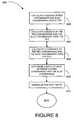
- FIGS. 7 and 8are flowcharts illustrating a method for processing a statistical property calculation in accordance with an example embodiment
- FIG. 9is a flowchart illustrating a method for pixel variable value shifting in accordance with an example embodiment
- FIG. 10is a flowchart illustrating a method for message decoding in accordance with an example embodiment
- FIG. 11is a flowchart illustrating a method for message bit decoding in accordance with an example embodiment
- FIG. 12is a flowchart illustrating a method for encoded region identification in accordance with an example embodiment
- FIG. 13is a flowchart illustrating a method for modulation pattern application during decoding in accordance with an example embodiment
- FIG. 14is a block diagram of an example encoder that may be deployed in the encoding system of FIG. 1 according to an example embodiment
- FIG. 15is a block diagram of an example optical decoder that may be deployed in the decoding system of FIG. 2 according to an example embodiment
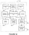
- FIG. 16is a block diagram of an example inline decoder that may be deployed in the decoding system of FIG. 2 according to an example embodiment.
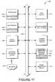
- FIG. 17illustrates a diagrammatic representation of a machine in the example form of a computer system within which a set of instructions for causing the machine to perform any one or more of the methodologies discussed herein may be executed.
- Example methods and systems for spatial data encoding and decodingare described.
- numerous specific detailsare set forth in order to provide a thorough understanding of example embodiments. It will be evident, however, to one skilled in the art that the present invention may be practiced without these specific details.
- a tilemay be designated within a source frame.
- the tilemay include a plurality of available pixels.
- the tilemay be divided into at least one bit area.
- a particular bit area of the at least one bit areamay be capable of being encoded with a message bit.
- a modulation pattern including a plurality of modulation pattern valuesmay be accessed.
- a particular message bit value of a messagemay be accessed.
- a statistical property calculationmay be performed on a pixel variable value of the plurality of available pixels within the tile.
- a pixel variable value of a plurality of pixels in the particular bit area of a target framemay be shifted to encode a particular message bit of the one or more message bits.
- a particular pixel variable value of a particular pixel of the plurality of pixelsmay be shifted by a shift value.
- the shift valuemay be in accordance with the statistical property calculation, the particular message bit value, and a particular modulation pattern value of the plurality of modulation pattern values for the particular pixel within the particular bit area.
- a comparison tilemay be identified within a source frame.
- the comparison tilemay include a plurality of available pixels. At least one bit area may be identified within the comparison tile. A particular bit area of the at least one bit area may be encoded with a message bit. The message bit may be associated with a message.
- a statistical property calculation for a plurality of pixel variable valuesmay be performed within the comparison tile.
- a modulation patternmay be applied to at least one bit area of a target frame. At least one message bit in a target frame may be identified in accordance with the performing of the statistical property calculation and the applying of the modulation pattern.
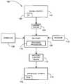
- FIG. 1illustrates an example encoding system 100 according to an example embodiment.
- the encoding system 100is an example platform in which one or more embodiments of an encoding method of the present invention may be used. However, other platforms may also be used.
- a content signal 104may be provided from a signal source 102 to an encoder 106 in the encoding system 100 .
- the content signal 104is one or more images and optionally associated audio.
- Examples of the content signal 104include standard definition (SD) and/or high definition (HD) content signals in NTSC (National Television Standards Committee), PAL (Phase Alternation Line), SECAM (Systeme Electronique Couleur Avec Memoire), a MPEG (Moving Picture Experts Group) signal, one or more JPEGs (Joint Photographic Experts Group) sequence of bitmaps, or other signal formats that transport of a sequence of images.
- the form of the content signal 104may be modified to enable implementations involving the content signals 104 of various formats and resolutions.
- the signal source 102is a unit that is capable of providing and/or reproducing one or more images electrically in the form of the content signal 104 .
- Examples of the signal source 102include a professional grade video tape player with a video tape, a camcorder, a stills camera, a video file server, a computer with an output port, a digital versatile disc (DVD) player with a DVD disc, and the like.
- An operator 108may interact with the encoder 106 to control its operation to encode a message 110 within the content signal 104 , thereby producing an encoded content signal 112 that may be provided to a broadcast source 114 .
- the operator 108may be a person that interacts with the encoder 106 (e.g., through the use of a computer or other electronic control device).
- the operator 108may consist entirely of hardware, firmware and/or software, or other electronic control device that directs operation of the encoder 106 in an automated manner.
- the encoded content signal 112may be provided to the broadcast source 114 for distribution and/or transmission to an end-user (e.g., a viewer) who may view the content associated with encoded content signal 112 .
- the broadcast source 114may deliver the encoded content signal 112 to one or more viewers in formats including analog and/or digital video by storage medium such as DVD, tapes, and other fixed medium and/or by transmission sources such as television broadcast stations, cable, satellite, wireless and Internet sources that broadcast or otherwise transmit content.
- the encoded content signal 112may be further encoded (e.g., MPEG encoding) at the broadcast source 114 prior to delivering the encoded content signal 112 to the one or more viewers. Additional encoding may occur at the encoder 106 , the broadcast source 114 , or anywhere else in the production chain.
- a message 110may be encoded within the encoded content signal 112 .
- Information included in the message 110may include, by way of example, a web site address, identification data (e.g., who owns a movie, who bought a movie, who produced a movie, where a movie was purchased, etc.), a promotional opportunity (e.g., an electronic coupon), authentication data (e.g., that a user is authorized to receive the content signal), non-pictorial data, and the like.
- the message 110may be used to track content (e.g., the showing of commercials).
- the message 110may provide an indication of a presence of rights associated with the encoded content signal 112 , provide a promotional opportunity, provide electronic game play enhancement, be a uniform resource locator (URL), be an electronic coupon, provide an index to a database, or the like.
- Multiple messages 110may optionally be encoded within the encoded content signal 112 .
- the message 110may be shared over multiple frames of the encoded content signal 112 .
- the message 110may be encoded in such a way that the arrangements of the message bits in the frame corresponds to a pattern that is capable of being matched or interpreted as one or more bar codes.
- the bar codemay be one-dimensional such as a UPC bar code.
- the bar codemay be multi-dimensional (e.g., two-dimensional bar codes such as an Aztec code, Data Matrix, Dataglyph, MaxiCode, PDF417, QR Code, Ultra Code or UCC RSS-2D bar code). Other machine readable representations of data in a visual form may also be used.
- Encoding of the message 110may be performed by an encoding subsystem 116 of the encoder 106 .
- An example embodiment of the encoding subsystem 116is described in greater detail below.
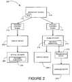
- FIG. 2illustrates an example decoding system 200 according to an example embodiment.
- the decoding system 200is an example platform in which one or more embodiments of a decoding method of the present invention may be used. However, other platforms may also be used.
- the decoding system 200may send the encoded content signal 112 from the broadcast source 114 (see FIG. 1 ) to a display device 206 . 1 and/or an inline decoder 210 .
- the inline decoder 210may receive (e.g., electrically) the encoded content signal 112 from the broadcast source 114 , and thereafter may transmit a transmission signal 212 to a signaled device 214 and optionally provide the encoded content signal 112 to a display device 206 . 2 .
- the inline decoder 210may decode the message 110 encoded within the encoded content signal 112 and transmit data regarding the message 110 to the signaled device 214 by use of the transmission signal 212 and provide the encoded content signal 112 to a display device 206 . 2 .
- the transmission signal 212may include a wireless radio frequency, infrared and direct wire connection, and other transmission mediums by which signals may be sent and received.
- the signaled device 214may be a device capable of receiving and processing the message 110 transmitted by the transmission signal 212 .
- the signaled device 214may be a DVD recorder, PC based or consumer electronic-based personal video recorder, and/or other devices capable of recording content to be viewed or any device capable of storing, redistributing and/or subsequently outputting or otherwise making the encoded content signal 112 available.
- the signaled device 214may be a hand-held device such as a portable gaming device, a toy, a mobile telephone, and/or a personal digital assistant (PDA).
- PDApersonal digital assistant
- the signaled device 214may be integrated with the inline decoder 210 .
- An optical decoder 208may receive and process the message 110 from a display device 206 . 1 .
- An implementation of the optical decoder 208is described in greater detail below.
- the display device 206 . 1may receive the encoded content signal 112 directly from the broadcast source 114 while the display device 206 . 2 may receive the encoded content signal 112 indirectly through the inline decoder 210 .
- the display devices 206 . 1 ., 206 . 2may be devices capable of presenting the content signal 104 and/or the encoded content signal 112 to a viewer such as an analog or digital television, but may additionally or alternatively include a device capable of recording the content signal 104 and/or the encoded content signal 112 such as a digital video recorder. Examples of the display devices 206 . 1 ., 206 . 2 may include, but are not limited to, projection televisions, plasma televisions, liquid crystal displays (LCD), personal computer (PC) screens, digital light processing (DLP), stadium displays, and devices that may incorporate displays such as toys and personal electronics.
- LCDliquid crystal displays
- PCpersonal computer
- DLPdigital light processing
- a decoder subsystem 216may be deployed in the optical decoder 208 and/or the inline decoder 210 to decode the message 110 in the encoded content signal 112 .
- An example embodiment of the decoder subsystem 216is described in greater detail below.
- FIG. 3illustrates an example encoding subsystem 116 that may be deployed in the encoder 106 of the encoding system 100 (see FIG. 1 ) or otherwise deployed in another system.
- the encoding subsystem 116may include a region access module 302 , a tile designation module 304 , a tile dividing module 306 , a modulation pattern access module 308 , a message access module 310 , a statistical property calculation module 312 , a message color factor determination module 314 , and/or a shifting module 316 . Other modules may also be used.
- the region access module 302accesses a region of a frame (e.g., a source frame).
- the tile designation module 304designates a tile within a frame.
- the tile dividing module 306divides the tile into one or more bit areas.
- the modulation pattern access module 308accesses a modulation pattern including a number of modulation pattern values.
- the message access module 310accesses a message bit value of the message 110 and/or or the message 110 .
- the statistical property calculation module 312performs a statistical property calculation on a number of pixel variable values of the number of available pixels within a tile.
- the message color factor determination module 314determines a message color factor for the message 110 .
- the shifting module 316shifts one or more pixel variable values of a number of pixels in the particular bit area of a target frame to encode one or more message bits.
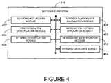
- FIG. 4illustrates an example decoder subsystem 216 that may be deployed in the optical decoder 208 and/or the inline decoder 210 of the decoding system 200 (see FIG. 2 ) or otherwise deployed in another system.
- the decoder subsystem 216may include a decoding key access module 402 , a comparison tile identification module 404 , a bit area identification module 406 , a statistical property calculation module 408 , a modulation pattern application module 410 , a message bit decoding module 412 , and/or a message translation module 414 . Other modules may also be used.
- the decoding key access module 402accesses a decoding key.
- the decoding keymay include identification of a comparison tile in a source frame.
- the comparison tilemay include a number of available pixels.
- the comparison tile identification module 404identifies a comparison tile within the source frame. The comparison tile may be identified in accordance with the decoding key accessed with the decoding key access module 402 .
- the bit area identification module 406identifies one or more bit areas within the comparison tile.
- the statistical property calculation module 408performs a statistical property calculation for a number of pixel variable values within the comparison tile.
- the modulation pattern application module 410applies a modulation pattern to one or more bit areas of a target frame.
- the message bit decoding module 412decodes one or more message bits in a target frame in accordance with the performing of the statistical property calculation by the statistical property calculation module 408 and the applying of the modulation pattern by the modulation pattern application module 410 .
- the message translation module 414translates on one or more message bits identified by the message bit identification module 412 over one or more frames into the message 110 .
- FIG. 5illustrates a method 500 for content signal encoding according to an example embodiment.
- the method 500may be performed by the encoder 106 (see FIG. 1 ) or otherwise performed.
- a region of a frame of the content signal 104may be accessed at block 502 .
- the regionis one or more contiguous or non-continuous portions of a frame containing a number of pixels where encoding may take place.
- Each of the number of pixelsmay be associated with a number of pixel variable values.
- the pixel variable valuesmay be YCrCb (luminance, red chrominance, blue chrominance), RGB (red, green, and blue), or YUV.
- Other pixel variable values specifying a pixel attributee.g., linear or nonlinear combinations of YCbCr, RGB, or YUB) may also be used.
- the regionmay be an entire frame or a portion of the frame.
- a regionmay be selected consistently over all frames of the content signal 104 , the same region may be selected for a number of frames and then a new region may be selected within the content signal 104 , or the region may be varied for the frames of the content signal 104 . Changing the region selection for the frames of the content signal 104 may reduce any obtrusiveness of the encoding.
- the regionmay be selected within a frame according to an area layout of the frame for the content signal 104 .
- available selections of the regionmay include a left quadrant, a right quadrant, left top, right top, bottom left, or bottom right.
- the region selectionmay vary on occasion or at different frequencies, where more frequent variations may be used to reduce obtrusiveness of the message.
- the regionmay be changed more or less frequently than every I-frame of the content signal 104 .
- the same regionmay be selected for a given I-frame and all frames up to but not including the next I-frame of the content signal.
- the selection of the same region between I-frames in MPEG encodingmay minimize disruption of MPEG data compression while maximizing an encoded data transmission rate.
- the tilemay be a frame selection that includes an entire region or a portion of a region (e.g., a subregion) of the frame. Different tiles may optionally be selected in a same frame for different pixel variable values (e.g., luminance, red chrominance and blue chrominance).
- the tileis a partial portion or an entire portion of one or more regions of a frame over which a statistical property calculation may be performed.
- the statistical property calculationmay include statistical calculations of means, variances, covariances and/or standard deviations for one or more of pixel variable values of a tile.
- the tiles selected over a number of frames of the content signal 104may be equal in size or may be differently sized.
- the tilesmay be a first size for a first pixel channel (e.g., red and blue chrominance) within the content signal 104 and a second differing size for a second pixel channel (e.g., luminance) within the same content signal 104 .
- a first pixel channele.g., red and blue chrominance
- a second pixel channele.g., luminance
- Each tilemay be divided into one or more bit areas at block 506 .
- a bit areais part of or an entire tile within which one message bit of the message 110 may be encoded. Additional bits may be used to allow for improved data retrieval on decoding.
- the arrangement of the bit areas in the framemay be in a square array or a hexagonal array. However, other types of regular and irregular patterns (e.g., derived from one or two dimensional bar codes) may also be used.
- the bit areasmay include dots as a resulting of the encoding.
- the bit areamay optionally be the size of an MPEG block (e.g., 8 ⁇ 8 or 16 ⁇ 16) but is not so limited.
- an MPEG blocke.g. 8 ⁇ 8 or 16 ⁇ 16
- the tilemay include 100 bit areas each of which is 8 ⁇ 8 pixels in size.
- a 16 ⁇ 16 chrominance macro block for the bit areamay be selected and a 32 ⁇ 32 luminance macro block of the bit area may be selected.
- any other size or shape bit areasmay also be used. For example, bit areas need not be square.
- the bit areas selected over the frames of the content signal 104may be equal in size or may be differently sized.
- the bit areasmay be a first size for a first channel (e.g., red and blue chrominance) within the content signal and a second differing size for a second channel (e.g., luminance) within the same content signal.
- the message 110may be accessed at block 508 .
- Each instance of the message 110 to be encoded in the content signal 104may contain between approximately five hundred to approximately one thousand message bits per frame, although a greater number or lesser number of message bits may also be used.
- the message bitsmay be part of a bit stream and may be used to represent the message 110 .
- the message 110may be encoded with extra bits to facilitate or enable error correction during decoding.
- the extra bitsmay be, but are not limited to, parity bits used by the Reed-Solomon technique or Data Matrix for error checking, or extra bits used to enable Manchester encoding.
- the use of the extra bits for error checkingmay enable a less obtrusive transmission of the message 110 within the content signal 104 by allowing the changes to pixel variable values involved in encoding to be made at low amplitude.
- a statistical property calculation for at least one pixel variable valuemay be performed for the one or more tiles in the region at block 510 as one input for calculation of one or more shift values.
- the at least one pixel variable valuemay be color values (e.g., the Cb, the Cr, the blue chrominance, the red chrominance) and/or a luminance value.
- a statistical property calculationmay be performed and used to obtain a linear combination of two color values. An example embodiment of performing the statistical property calculation is described in greater detail below.
- the statistical property calculationmay be used to calculate the amount of dispersion in pixel variable values in a frame in which the message 110 is to be encoded.
- a determinationmay be made as to whether the calculated value of the statistical property calculation is a linear combination of two values. If a determination is made that the calculated value is a linear combination of two values, the linear combination of the calculated value may be normalized at block 514 to specify the relative strength of encoding in the two sets of pixel variable values. For example, the linear combination of the color values may be normalized.
- the method 500may proceed to block 516 .
- the pixel values of a plurality of pixelsmay be shifted in accordance with the shift value.
- the shift valuemay be calculated from at least one pixel variable value within a tile.
- the shifting of the colormay create a shape in a bit area specified by the modulating pattern (e.g., a dot). An example embodiment of shifting the pixel values in the bit areas is described in greater detail below.
- the method 500may encode the same data for several frames before a shift occurs.
- the method 500may also be used with a number of shift values. For example a shift value may be calculated separately for the luminance value and the at least one color value, and the shift for the luminance value and the at least one color value may occur in the same or different bit areas.
- FIG. 6illustrates a method 600 for frame encoding according to an example embodiment.
- the method 600may be performed by the encoder 106 (see FIG. 1 ) or otherwise performed.
- a tileis designated within a source frame (e.g., of the content signal 104 ) at block 602 .
- the tilemay include a number of available pixels.
- the tileis divided into one or more bit areas.
- a bit areamay be capable of being encoded with a message bit.
- a modulation pattern including a number of modulation pattern valuesis accessed at block 606 .
- the modulation patternmay be defined for each pixel value corresponding to each pixel of a bit area and may have values that are positive or negative. It may, but need not, be chosen to have values that are generally smaller near the edges of the bit area. For example, in encoding an amount that is proportional to the modulation pattern may be applied over the bit area so that the edges of the bit area have the least amount of shift while the center of the bit area has the greatest amount of shift.
- the modulation patternmay be a two-dimensional Gaussian function (power 2) or pseudo-Gaussian function (power other than 2) but is not so limited.
- a message bitmay be encoded by incrementing or decrementing pixel values by an amount that varies across the bit area (e.g., by an amount proportional to the modulation pattern).
- the modulation patternmay be selected to minimize intrusiveness and/or for robustness against compression.
- the discrete cosine transform (DCT) spacemay be used to aid in designing a modulation pattern for robustness against compression or other desired features.
- DCTdiscrete cosine transform
- a real space patternmay be imported into DCT space, high frequency components that are not resistant to compression and/or low frequency components that are more visible may be removed leaving the medium range components.
- the resulting pattern in DCT spacemay be converted back into real space and the real space result may be used as the modulation pattern for encoding.
- a scaling distance of the modulation pattern(e.g., the standard deviation when the modulation pattern is the Gaussian function) may be selected so that a value from the modulation pattern falls off to almost zero near the edges of the bit area.
- the scaling distancemay be selected as one quarter to one sixth of the size of the bit area, but other scaling distances may also be used.
- a message bit value of the message 110is accessed at block 608 .
- the corresponding position of the message 110may indicate that a black pixel (e.g., a value of zero) or white pixel (e.g., a value of one) from the message is to be encoded in the bit area.
- the message bit valuemay be a value of one if the corresponding position of the message 110 indicates that a black pixel is to be encoded, and the message bit may be a value of negative one if the corresponding position of the message 110 indicates that a white pixel is to be encoded.
- the correspondence with the black pixel and a positive one and the white pixel and a negative onemay be reversed so that the white pixel corresponds with the positive one and the black pixel with the negative one and other values beyond one may be used.
- a “0” data bitmay be encoded by decrementing a chosen variable and encoded a “1” by incrementing it, or vice versa.
- a statistical property calculationis performed on one or more pixel variable values of the number of available pixels within the tile.
- a message color factormay be determined for the message 110 at block 612 .
- a shift valuemay be normalized at block 614 .
- the shift valuemay be in accordance with the statistical property calculation, the particular message bit value, a particular modulation pattern value of the number of modulation pattern values for the particular pixel within the particular bit area, and/or a message color factor.
- one or more pixel variable values of a number of pixels in the one or more bit areas of a target framemay be shifted to encode a message bit in each of the one or more bit areas.
- a pixel variable valuemay be shifted by a shift value (or a normalized shift value).
- the target framemay be the source frame or a different frame in which the one or more bits are shifted.
- the target framemay be a preceding frame or subsequent frame in the content signal 104 .
- the target framemay have substantially similar properties to source frame.
- the similar propertiesmay include, by way of example, similar pixel variable values and/or comparable tiles.
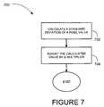
- FIG. 7illustrates a method 700 for processing a statistical property calculation according to an example embodiment.
- the method 700may be performed at block 510 , block 610 , or otherwise performed.
- a standard deviation of a pixel variable valuemay be calculated for a tile at block 702 .
- the standard deviation of luminance, red chrominance, or blue chrominancemay be calculated for a tile.
- the calculated valuemay be adjusted by a multiplier at block 704 .
- FIG. 8illustrates a method 800 for processing a statistical property calculation according to an example embodiment is illustrated.
- the method 700may be performed at block 510 , block 610 , or otherwise performed.
- a red chrominance average and a blue chrominance averagemay be calculated for a tile at block 802 .
- the red chrominance averagemay be calculated by taking an average of red chrominance over a tile
- the blue chrominance averagemay be calculated by taking an average of blue chrominance over the tile.
- designation of the region into tiles that are smaller than the entire frame for the statistical property calculation as opposed to performing the calculation over the entire framemay enable shifting by a smaller amount of some combination of red chrominance and blue chrominance or luminance in the case of encoding in luminance) while still being able to recover the message.
- the selection of a smaller tilemay provide for less variation in chrominance or luminance over each individual tile as compared to the variation over the entire frame.
- a red chrominance variance(e.g., a variance or dispersion of the red chrominance) and a blue chrominance variance (e.g., a variance or dispersion of the blue chrominance) may be calculated for the frame selection at block 804 .
- the red chrominance variancemay be calculated by determining a variance or dispersion of the red chrominance
- a blue chrominance variancemay be calculated by determining a variance or dispersion of the blue chrominance.
- the standard deviationmay also be derived from the variance.
- a covariancemay be calculated for the red chrominance and the blue chrominance at block 806 .
- a color ratio specifying the proportions of red and blue chrominance values in a linear combination of those valuesmay be determined at block 808 .
- using the color ratio as part of the shift valuemay minimize the standard deviation of the linear combination of the red and blue chrominances over the potential linear combinations (e.g., all potential linear combinations) for that tile of the frame.
- the selection of the color ratiomay minimize the amount of relative adjustment made to the red chrominance and blue chrominance (e.g., to limit obtrusiveness).
- the color ratiomay be normalized (e.g., so that the amplitude is one) at block 810 .
- any two pixel variable values of the pixelsmay be used.
- FIG. 9illustrates a method 900 for pixel variable value shifting according to an example embodiment.
- the method 900may be performed at block 516 or block 616 (see FIGS. 5 and 6 ).
- a modulation patternmay be accessed at block 902 .
- a message color factormay optionally be determined for a message 110 at block 904 .
- the message color factormay take into consideration a relative number of white bits and black bits in the message 110 .
- the message color factormay be applied by dividing by a number proportional to the number of white bits to be encoded in the tile for a white bit and dividing by a number proportional to the number of black bits to be encoded in the tile for a black bit.
- the use of the message color factormay enable the mean value of the red chrominance and the blue chrominance and/or the luminance to remain the same after encoding.
- a bit area of a regionmay be accessed at block 906 .
- a message bit valuemay be accessed at block 908 .
- a pixel of the bit areamay be accessed at block 910 .
- At least one pixel variable valuemay be shifted at block 912 according to one or more shift factors.
- the shifting of the at least one pixel variable value of a number of pixelsmay encode the content signal 104 at a spatial frequency where eye is less sensitive (e.g., more insensitive) to variations in chrominance and/or luminance.
- shifting the red chrominance and the blue chrominance during the operations of block 912may create a dot (e.g., one or more pixels having a greatest amount of chrominance adjustment) that may be detected during decoding but may be substantially invisible to human eyes.
- a dote.g., one or more pixels having a greatest amount of chrominance adjustment
- a determinationmay be made as to whether another pixel of the bit area may be accessed. If a determination is made to access another pixel, the method 900 may return to block 910 . If a determination is made at decision block 914 not to access another pixel, the method 900 may proceed to decision block 916 .
- FIG. 10illustrates a method 1000 for message decoding according to an example embodiment.
- the method 1000may be performed by the optical decoder 208 , the inline decoder 210 (see FIG. 2 ), or otherwise performed.
- An encoded region of a frame(e.g., of the encoded content signal 112 ) may be identified at block at block 1002 .
- the encoded regionmay, by way of example, be identified using Fast Fourier transforms, by using identifiable regions on a display, by using a visible or substantially invisible test pattern, or by identifying the edges of a TV screen using the property that the luminance of a TV screen may be higher than the luminance of a surrounding area. Other methods for identifying an encoded region of a frame or several methods in combination may also be used.
- bit areas of the encoded regionmay be identified at block 1004 .
- the bit areasmay be identified by having knowledge of the size of a bit area and using the bit area size to identify the bit areas in the region.
- a modulation patternmay be applied to the one or more bit areas of the encoded region at block 1006 .
- the modulation patternmay be a modulation pattern used during encoding or a pattern similar to the modulation pattern used during encoding. An example embodiment of applying the modulation pattern is described in greater detail below.
- Message bitsmay be determined for the bit areas at block 1008 .
- An example embodiment of determining the message bitsis described in greater detail below.
- One or more messages 110may be obtained by decoding the message bits from the encoded content signal 112 at block 1010 .
- FIG. 11illustrates a method 1100 for message bit decoding according to an example embodiment.
- the method 1100may be performed by the optical decoder 208 , the inline decoder 210 (see FIG. 2 ), or otherwise performed.
- a decoding keymay be accessed at block 1102 .
- the decoding keymay include identification of the comparison tile in the source frame.
- a comparison tileis identified within a source frame at block 1104 .
- the comparison tilemay include a number of available pixels.
- the comparison tilemay be identified in accordance with the decoding key or otherwise identified.
- At least one bit areais identified within the comparison tile at block 1106 .
- a bit areamay be capable of being encoded with a message bit.
- the message bitmay be associated with the message 110 .
- a statistical property calculationis performed for a number of pixel variable values within the comparison tile.
- a modulation patternis applied to at least one bit area of a target frame at block 1110 .
- one or more message bitsare identified in a target frame in accordance with the performing of the statistical property calculation and the applying of the modulation pattern.
- the target framemay be the source frame or a different frame in which the one or more bits are shifted.
- the target framemay be a preceding frame or subsequent frame in the content signal 104 .
- the target framemay have substantially similar properties to source frame.
- the similar propertiesmay include, by way of example, similar pixel variable values and/or comparable tiles.
- FIG. 12illustrates a method 1200 for encoded region identification according to an example embodiment is illustrated.
- the method 1200may be performed at block 1002 (see FIG. 10 ) or otherwise performed.
- a decoding keymay be accessed for the encoded content signal 112 at block 1202 .
- the decoding keymay be software and/or hardware available to or embodied in a detector that identifies the encoded region in the frames of the encoded content signal 112 .
- the decoding keymay include, by way of an example, the modulation pattern, the positions of the region and tiles within the frames, how many bits are being encoded, the size and shape of the bit areas, the spatial orientation of the encoding, specification of which of the one or more pixel variable values have been used in the encoding, whether optimal or fixed combinations of pixel variable values are used, and the like.
- the decoding keymay also include other components to be used to decode the message 110 in the encoded content signal 112 .
- a frame of the encoded content signal 112may be accessed at block 1204 .
- An encoded region of the framemay be accessed by use of the decoding key at block 1206 .
- FIG. 13illustrates a method 1300 for modulation pattern application during decoding according to an example embodiment.
- the method 1300may be performed at block 1006 , at block 1106 , or otherwise performed.
- a modulation patternmay be accessed at block 1302 .
- the modulation patternmay be accessed from the decoding key or otherwise determined.
- other information used to decode the encoded content signal 112may also be obtained from the decoding key.
- the modulation patternmay be the modulation pattern used to modulate the content signal 104 , or may be a pattern that is similar and/or correlated to the modulation pattern used to modulate the content signal 104 .
- the average pattern value of the pattern valuemay be calculated over the tile at block 1303 .
- a tile of the framemay be access at block 1304 .
- the tilemay be accessed from the decoding key, may be determinable, or may otherwise be available.
- a shift ratiomay be determined for the tile at block 1306 .
- the shift ratiomay be calculated by performing a statistical property calculation as described in greater detail above.
- the shift ratiomay be adjusted to account for the changes to the pixel variable values introduced by the encoding process.
- the adjusted shift ratiomay more accurately reflect the values used during the encoding process.
- a bit areamay be accessed at block 1308 .
- the average pixel variable value of the at least one pixel valuemay be calculated over the tile at block 1310 .
- a pixel of the bit areamay be accessed at block 1312 .
- a matched filtermay be applied to the at least one pixel variable value of the pixel and block 1314 .
- the modulation patternmay be applied as a matched filter.
- the modulating pattern, minus its average over the bit area,may optionally be used as the matched filter during the operations at block 1314 .
- the average pixel variable value of the linear combination of the at least one pixel variable value selectedmay optionally be subtracted from the at least one pixel variable value of the pixel from the linear combination during the operations at block 1314 .
- applying the matched filtermay include for each pixel subtracting the average pixel variable value (over the bit area) from the pixel variable value for the pixel and multiplying the result by the result of subtracting the average pattern value (over the bit area) from the pattern value for the pixel to obtain a numeric value.
- the encoded datamay be received by convolving a chosen variable with a matching filter that has a similar functional form across the bit area as the encoded amount during encoding and/or by another filter that compares a mean value of the chosen variable in portions of the data bit area where it is incremented or decremented by a comparatively large amount to encode data to values of that variable in portions of the data bit area where it is incremented or decremented less or not at all.
- a determinationmay be made as to whether another pixel of the bit area may be accessed. If a determination is made to access another pixel, the method 1300 may return to block 1312 . If a determination is made at decision block 1316 not to access another pixel, the method 1300 may proceed to block 1318 .
- An averagemay be calculated from the numerical values obtained by applying the matched filter at block 1318 .
- the filtered averagemay be used to determine whether the at least one pixel variable value in the bit area were on average raised or lowered.
- the functionmay be (L-Lav)(p-pav) where L is at least pixel variable value, Lav is the average of the at least pixel variable value over the bit area, p is the pattern value for that pixel and pav is its average over the bit area.
- Lat least pixel variable value
- Lavis the average of the at least pixel variable value over the bit area
- pis the pattern value for that pixel
- pavis its average over the bit area.
- FIG. 14illustrates an example encoder 106 (see FIG. 1 ) that may be deployed in the encoding system 100 or another system.
- the encoder 106may be a computer with specialized input/output hardware, an application specific circuit, programmable hardware, an integrated circuit, an application software unit, a central process unit (CPU) and/or other hardware and/or software combinations.
- the encoder 106may include an encoder processing unit 1402 that may direct operation of the encoder 106 .
- the encoder processing unit 1402may alter attributes of the content signal 104 to produce the encoded content signal 112 containing the message 110 .
- a digital video input 1404may be in operative association with the encoder processing unit 1402 and may be capable of receiving the content signal 104 from the signal source 102 .
- the encoder 106may additionally or alternatively receive an analog content signal 104 through an analog video input 1406 and an analog-to-digital converter 1408 .
- the analog-to-digital converter 1408may digitize the analog content signal 104 such that a digitized content signal 104 may be provided to the encoder processing unit 1402 .
- An operator interface 1410may be operatively associated with encoder processing unit 1402 and may provide the encoder processing unit 1402 with instructions including where, when and/or at what magnitude the encoder 106 should selectively raise and/or lower a pixel value (e.g., the luminance and/or chrominance level of one or more pixels or groupings thereof at the direction of the operator 108 ).
- the instructionsmay be obtained by the operator interface 1410 through a port and/or an integrated operator interface.
- other device interconnects of the encoder 106may be used including a serial port, universal serial bus (USB), “Firewire” protocol (IEEE 1394), and/or various wireless protocols.
- responsibilities of the operator 108 and/or the operator interface 1410may be partially or wholly integrated with the encoder software 1414 such that the encoder 106 may operate in an automated manner.
- the encoder processing unit 1402may store the luminance values and/or chrominance values as desired of the content signal 104 in storage 1412 .
- the storage 1412may have the capacity to hold and retain signals (e.g., fields and/or frames of the content signal 104 and corresponding audio signals) in a digital form for access (e.g., by the encoder processing unit 1402 ).
- the storage 1412may be primary storage and/or secondary storage, and may include memory.
- the encoder 106may send the resulting encoded content signal 112 in a digital format through a digital video output 1416 or in an analog format by converting the resulting digital signal with a digital-to-analog converter 1418 and outputting the encoded content signal 112 by an analog video output 1420 .
- the encoder 106need not include both the digital video input 1404 and the digital video output 1416 in combination with the analog video input 1406 and the analog video output 1420 . Rather, a lesser number of the inputs 1404 , 1406 and/or the outputs 1416 , 1420 may be included. In addition, other forms of inputting and/or outputting the content signal 104 (and the encoded content signal 112 ) may be interchangeably used.
- components used by the encoder 106may differ when the functionality of the encoder 106 is included in a pre-existing device as opposed to a stand alone custom device.
- the encoder 106may include varying degrees of hardware and/or software, as various components may interchangeably be used.
- FIG. 15illustrates an example optical decoder 208 (see FIG. 2 ) that may be deployed in the decoding system 200 or another system.
- the optical decoder 208may include an imaging sensor device 1506 operatively associated with an analog-to-digital converter 1508 and a decoder processing unit 1502 to optically detect the encoded content signal 112 (e.g., as may be presented on the display device 206 . 1 ., 206 . 2 of FIG. 2 ).
- the imaging sensor device 1506may be a CMOS (Complimentary Metal Oxide Semiconductor) imaging sensor, while in another example embodiment the imaging sensor device may be a CCD (Charge-Coupled Device) imaging sensor.
- the imaging sensor device 1506may be in focus to detect motion on the display device 206 . 1 , 206 . 2 relative to background.
- the decoder processing unit 1502may be an application specific circuit, programmable hardware, integrated circuit, application software unit, and/or hardware and/or software combination.
- the decoder processing unit 1502may store the values (e.g., luminance, chrominance, or luminance and chrominance) of the encoded content signal 112 in storage 1512 and may detect pixels that have increased and/or decreased pixel values.
- the decoder processing unit 1502may process the encoded content signal 112 to detect the message 110 .
- a filter 1504may be placed over a lens of the imaging sensor device 1506 to enhance the readability of the message 110 contained within the encoded content signal 112 .
- an optical filtere.g., a red filter or a green filter
- a digital filter and other types of filtersmay also be used.
- a signal output 1514may be electrically coupled to the decoder processing unit 1502 and provide a data output for the message 110 and/or data associated with the message 110 after further processing by the optical decoder 208 .
- the data outputmay be one-bit data and/or multi-bit data.
- An optional visual indicator 1516may be further electrically coupled to the decoder processing unit 1502 and may provide a visual and/or audio feedback to a user of the optical decoder 208 , which may by way of example include notice of availability of promotional opportunities based on the receipt of the message.
- the decoder processing unit 1502may store the pixel variable values of the encoded content signal 112 in the storage 1512 and detect the alteration to the pixel variable values of the encoded content signal 112 .
- the functionality of the storage 1512may include the functionality of the storage 1412 (see FIG. 14 ).
- FIG. 16illustrates an example inline decoder 210 (see FIG. 2 ) that may be deployed in the decoding system 200 or another system.
- the inline decoder 210may include an analog video input 1606 to receive the encoded content signal 112 from the broadcast source 114 when the encoded content signal 112 is an analog format, and a digital video input 1604 for receiving the encoded content signal 112 when the encoded content signal 112 is in a digital format.
- the digital video input 1604may directly pass the encoded content signal 112 to a decoder processing unit 1602
- the analog video input 1606may digitize the encoded content signal 112 by use of an analog-to-digital converter 1608 before passing the encoded content signal 112 to the decoder processing unit 1602 .
- other configurations of inputs and/or outputs of encoded content signal 112may also be used.
- the decoder processing unit 1602may process the encoded content signal 112 to detect the message 110 .
- the decoder processing unit 1602may be an application specific circuit, programmable hardware, integrated circuit, application software unit, and/or hardware and/or software combination.
- the decoder processing unit 1602may store the pixel values (e.g., luminance, chrominance, or luminance and chrominance) of the encoded content signal 112 in storage 1610 and may detect pixels that have increased or decreased pixel values.
- the decoder processing unit 1602may process the encoded content signal 112 to detect the message 110 .
- the message 110may be transferred from the inline decoder 210 to the signaled device 214 (see FIG. 2 ) by a signal output 1614 .
- the inline decoder 210may optionally output the encoded content signal 112 in a digital format through a digital video output 1616 and/or in an analog format by first converting the encoded content signal 112 from the digital format to the analog format by use of an digital-to-analog converter 1618 , and then outputting the encoded content signal 112 through an analog video output 1620 .
- the inline decoder 210need not output the encoded content signal 112 unless otherwise desired.
- FIG. 17shows a diagrammatic representation of machine in the example form of a computer system 1700 within which a set of instructions may be executed causing the machine to perform any one or more of the methods, processes, operations, or methodologies discussed herein.
- the signal source 102 , the encoder 106 , the broadcast source 114 , the display device 206 . 1 , 206 . 2 , the optical decoder 208 , the inline decoder 210 , and/or the signaled device 214may include the functionality of the computer system 1700 .
- the machineoperates as a standalone device or may be connected (e.g., networked) to other machines.
- the machinemay operate in the capacity of a server or a client machine in server-client network environment, or as a peer machine in a peer-to-peer (or distributed) network environment.
- the machinemay be a server computer, a client computer, a personal computer (PC), a tablet PC, a set-top box (STB), a Personal Digital Assistant (PDA), a cellular telephone, a web appliance, a network router, switch or bridge, or any machine capable of executing a set of instructions (sequential or otherwise) that specify actions to be taken by that machine.
- PCpersonal computer
- PDAPersonal Digital Assistant
- the example computer system 1700includes a processor 1702 (e.g., a central processing unit (CPU) a graphics processing unit (GPU) or both), a main memory 1704 and a static memory 1706 , which communicate with each other via a bus 1708 .
- the computer system 1700may further include a video display unit 1710 (e.g., a liquid crystal display (LCD) or a cathode ray tube (CRT)).
- the computer system 1700also includes an alphanumeric input device 1712 (e.g., a keyboard), a cursor control device 1714 (e.g., a mouse), a drive unit 1716 , a signal generation device 1718 (e.g., a speaker) and a network interface device 1720 .
- the drive unit 1716includes a machine-readable medium 1722 on which is stored one or more sets of instructions (e.g., software 1724 ) embodying any one or more of the methodologies or functions described herein.
- the software 1724may also reside, completely or at least partially, within the main memory 1704 and/or within the processor 1702 during execution thereof by the computer system 1700 , the main memory 1704 and the processor 1702 also constituting machine-readable media.
- the software 1724may further be transmitted or received over a network 1726 via the network interface device 1720 .
- machine-readable medium 1722is shown in an example embodiment to be a single medium, the term “machine-readable medium” should be taken to include a single medium or multiple media (e.g., a centralized or distributed database, and/or associated caches and servers) that store the one or more sets of instructions.
- the term “machine-readable medium”shall also be taken to include any medium that is capable of storing, encoding or carrying a set of instructions for execution by the machine and that cause the machine to perform any one or more of the methodologies shown in the various embodiments of the present invention.
- the term “machine-readable medium”shall accordingly be taken to include, but not be limited to, solid-state memories, optical and magnetic media, and carrier wave signals.
- a module or a mechanismmay be a unit of distinct functionality that can provide information to, and receive information from, other modules. Accordingly, the described modules may be regarded as being communicatively coupled. Modules may also initiate communication with input or output devices, and can operate on a resource (e.g., a collection of information).
- the modulesbe implemented as hardware circuitry, optical components, single or multi-processor circuits, memory circuits, software program modules and objects, firmware, and combinations thereof, as appropriate for particular implementations of various embodiments.
Landscapes
- Engineering & Computer Science (AREA)
- Multimedia (AREA)
- Signal Processing (AREA)
- Compression Or Coding Systems Of Tv Signals (AREA)
Abstract
Description
Claims (21)
Priority Applications (2)
| Application Number | Priority Date | Filing Date | Title |
|---|---|---|---|
| US12/001,545US7974438B2 (en) | 2006-12-11 | 2007-12-11 | Spatial data encoding and decoding |
| US13/094,742US8295622B2 (en) | 2006-12-11 | 2011-04-26 | Spatial data encoding and decoding |
Applications Claiming Priority (4)
| Application Number | Priority Date | Filing Date | Title |
|---|---|---|---|
| US87437306P | 2006-12-11 | 2006-12-11 | |
| US88361907P | 2007-01-05 | 2007-01-05 | |
| US90967107P | 2007-04-02 | 2007-04-02 | |
| US12/001,545US7974438B2 (en) | 2006-12-11 | 2007-12-11 | Spatial data encoding and decoding |
Related Child Applications (1)
| Application Number | Title | Priority Date | Filing Date |
|---|---|---|---|
| US13/094,742DivisionUS8295622B2 (en) | 2006-12-11 | 2011-04-26 | Spatial data encoding and decoding |
Publications (2)
| Publication Number | Publication Date |
|---|---|
| US20080193023A1 US20080193023A1 (en) | 2008-08-14 |
| US7974438B2true US7974438B2 (en) | 2011-07-05 |
Family
ID=39512054
Family Applications (2)
| Application Number | Title | Priority Date | Filing Date |
|---|---|---|---|
| US12/001,545Active2030-02-17US7974438B2 (en) | 2006-12-11 | 2007-12-11 | Spatial data encoding and decoding |
| US13/094,742ActiveUS8295622B2 (en) | 2006-12-11 | 2011-04-26 | Spatial data encoding and decoding |
Family Applications After (1)
| Application Number | Title | Priority Date | Filing Date |
|---|---|---|---|
| US13/094,742ActiveUS8295622B2 (en) | 2006-12-11 | 2011-04-26 | Spatial data encoding and decoding |
Country Status (2)
| Country | Link |
|---|---|
| US (2) | US7974438B2 (en) |
| WO (1) | WO2008073455A1 (en) |
Cited By (2)
| Publication number | Priority date | Publication date | Assignee | Title |
|---|---|---|---|---|
| US20080193046A1 (en)* | 2007-01-05 | 2008-08-14 | Koplar Interactive Systems International, L.L.C | Method and system for image registration |
| US11544748B2 (en) | 2017-10-26 | 2023-01-03 | Advocado, Inc | Online advertising and promotional coordination system |
Families Citing this family (13)
| Publication number | Priority date | Publication date | Assignee | Title |
|---|---|---|---|---|
| US7757095B2 (en)* | 2004-02-03 | 2010-07-13 | Tdk Corporation | Personal identification method, personal identification system, and optical information recording medium |
| US7974435B2 (en)* | 2005-09-16 | 2011-07-05 | Koplar Interactive Systems International Llc | Pattern-based encoding and detection |
| GB201122022D0 (en) | 2011-12-20 | 2012-02-01 | Imagination Tech Ltd | Method and apparatus for compressing and decompressing data |
| US8936194B1 (en) | 2013-03-15 | 2015-01-20 | Wunderlich-Malec Engineering, Inc. | Methods and systems for using two-dimensional matrix codes associated with panel component and equipment information and quality control |
| US20150035846A1 (en)* | 2013-08-02 | 2015-02-05 | Alex Ioannidis | Scannable time-varied geometric representation of data |
| US9313360B2 (en)* | 2014-07-30 | 2016-04-12 | Hewlett-Packard Development Company, L.P. | Encoding data in an image |
| US10462477B2 (en) | 2015-02-25 | 2019-10-29 | Cinova Media | Partial evaluator system and method |
| WO2017066346A1 (en)* | 2015-10-12 | 2017-04-20 | Cinova Media | Method and apparatus for optimizing video streaming for virtual reality |
| US10460700B1 (en) | 2015-10-12 | 2019-10-29 | Cinova Media | Method and apparatus for improving quality of experience and bandwidth in virtual reality streaming systems |
| US12212751B1 (en) | 2017-05-09 | 2025-01-28 | Cinova Media | Video quality improvements system and method for virtual reality |
| US10944971B1 (en) | 2017-05-22 | 2021-03-09 | Cinova Media | Method and apparatus for frame accurate field of view switching for virtual reality |
| CN109495756B (en)* | 2018-05-24 | 2022-11-01 | 曜科智能科技(上海)有限公司 | Self-adaptive motion search method based on rotation scaling |
| US11503310B2 (en)* | 2018-10-31 | 2022-11-15 | Ati Technologies Ulc | Method and apparatus for an HDR hardware processor inline to hardware encoder and decoder |
Citations (66)
| Publication number | Priority date | Publication date | Assignee | Title |
|---|---|---|---|---|
| US4807031A (en) | 1987-10-20 | 1989-02-21 | Interactive Systems, Incorporated | Interactive video method and apparatus |
| US5305104A (en) | 1992-07-27 | 1994-04-19 | The Trustees Of Columbia University In The City Of New York | Digitally assisted motion compensated deinterlacing for enhanced definition television |
| US5521984A (en) | 1993-06-10 | 1996-05-28 | Verification Technologies, Inc. | System for registration, identification and verification of items utilizing unique intrinsic features |
| US5594493A (en) | 1994-01-19 | 1997-01-14 | Nemirofsky; Frank R. | Television signal activated interactive smart card system |
| US5644363A (en) | 1995-03-24 | 1997-07-01 | The Advanced Learning Corp. | Apparatus for superimposing visual subliminal instructional materials on a video signal |
| US5880769A (en) | 1994-01-19 | 1999-03-09 | Smarttv Co. | Interactive smart card system for integrating the provision of remote and local services |
| EP0957448A2 (en) | 1998-05-15 | 1999-11-17 | PSC Scanning, Inc. | Optical code reader mouse |
| WO1999064980A1 (en) | 1998-06-12 | 1999-12-16 | Symbol Technologies, Inc. | Imaging engine and method for code readers |
| US6094228A (en) | 1997-10-28 | 2000-07-25 | Ciardullo; Daniel Andrew | Method for transmitting data on viewable portion of a video signal |
| US6215526B1 (en) | 1998-11-06 | 2001-04-10 | Tivo, Inc. | Analog video tagging and encoding system |
| US20010009867A1 (en) | 2000-01-20 | 2001-07-26 | Square Co., Ltd. | Game system for providing video game situation-solving information online |
| US20010017932A1 (en) | 1998-08-22 | 2001-08-30 | Chang Kenneth H.P. | Encoding and recording a message within an image |
| US6285774B1 (en) | 1998-06-08 | 2001-09-04 | Digital Video Express, L.P. | System and methodology for tracing to a source of unauthorized copying of prerecorded proprietary material, such as movies |
| US20020016750A1 (en) | 2000-06-20 | 2002-02-07 | Olivier Attia | System and method for scan-based input, storage and retrieval of information over an interactive communication network |
| US6370275B1 (en) | 1997-10-09 | 2002-04-09 | Thomson Multimedia | Process and device for scanning a plasma panel |
| US6404440B1 (en) | 1997-04-25 | 2002-06-11 | Thomson Multimedia | Process and device for rotating-code addressing for plasma displays |
| US20020080271A1 (en) | 2000-11-08 | 2002-06-27 | Jan Eveleens | Method and device communicating a command |
| US20020112250A1 (en) | 2000-04-07 | 2002-08-15 | Koplar Edward J. | Universal methods and device for hand-held promotional opportunities |
| US6449379B1 (en) | 1993-11-18 | 2002-09-10 | Digimarc Corporation | Video steganography methods avoiding introduction of fixed pattern noise |
| US6473804B1 (en) | 1999-01-15 | 2002-10-29 | Grischa Corporation | System for indexical triggers in enhanced video productions by redirecting request to newly generated URI based on extracted parameter of first URI |
| US20020183102A1 (en) | 2001-04-21 | 2002-12-05 | Withers James G. | RBDS method and device for processing promotional opportunities |
| US6604682B2 (en) | 2000-04-06 | 2003-08-12 | Seiko Epson Corporation | Method of and apparatus for reading a two-dimensional bar code symbol and data storage medium |
| US20030189731A1 (en) | 2002-04-06 | 2003-10-09 | Chang Kenneth H.P. | Print user interface system and its applications |
| US6661905B1 (en) | 1998-03-23 | 2003-12-09 | Koplar Interactive Systems International Llc | Method for transmitting data on a viewable portion of a video signal |
| US20030229900A1 (en) | 2002-05-10 | 2003-12-11 | Richard Reisman | Method and apparatus for browsing using multiple coordinated device sets |
| US20040130552A1 (en) | 1998-08-20 | 2004-07-08 | Duluk Jerome F. | Deferred shading graphics pipeline processor having advanced features |
| US6766956B1 (en) | 2000-06-08 | 2004-07-27 | United Video Properties, Inc. | System and method for using portable device with bar-code scanner |
| US20040262399A1 (en) | 1994-03-04 | 2004-12-30 | Longacre Andrew Jr | Optical reader comprising illumination assembly and solid state image sensor |
| US20050004844A1 (en) | 2003-04-23 | 2005-01-06 | Olivier Attia | Integrating barcode scanner enabled services in existing e-commerce applications using a floating pop-up web window |
| US20050015310A1 (en) | 2003-07-16 | 2005-01-20 | Didier Frantz | System and method for aggregating and managing client orders using barcode scanning technology |
| US20050011957A1 (en) | 2003-07-16 | 2005-01-20 | Olivier Attia | System and method for decoding and analyzing barcodes using a mobile device |
| US20050015311A1 (en) | 2003-07-16 | 2005-01-20 | Didier Frantz | System and method for aggregate online ordering using barcode scanners |
| US20050029356A1 (en) | 2003-08-05 | 2005-02-10 | Didier Frantz | Scanner reader Active-X plug-in |
| US20050033599A1 (en) | 2003-08-05 | 2005-02-10 | Didier Frantz | Printing on-the-fly barcoded documents |
| US20050029354A1 (en) | 2003-08-05 | 2005-02-10 | Didier Frantz | System associating sets of data into one barcode |
| US20050035206A1 (en) | 2003-08-11 | 2005-02-17 | Olivier Attia | Group average filter algorithm for digital image processing |
| US20050082370A1 (en) | 2003-10-17 | 2005-04-21 | Didier Frantz | System and method for decoding barcodes using digital imaging techniques |
| US20050094031A1 (en) | 2003-10-31 | 2005-05-05 | Tecot Edward M. | Interface strategies for creating and invoking marks |
| US20050125301A1 (en) | 2003-12-04 | 2005-06-09 | Ashish Muni | System and method for on the spot purchasing by scanning barcodes from screens with a mobile device |
| US20050121521A1 (en) | 2003-12-04 | 2005-06-09 | Rashmi Ghai | Section based algorithm for image enhancement |
| US20050246196A1 (en) | 2004-04-28 | 2005-11-03 | Didier Frantz | Real-time behavior monitoring system |
| US20050264694A1 (en) | 2002-08-20 | 2005-12-01 | Optinetix (Israel ) Ltd. | Method and apparatus for transferring data within viewable portion of video signal |
| US20060011728A1 (en) | 2004-07-14 | 2006-01-19 | Didier Frantz | Mobile device gateway providing access to instant information |
| US20060023963A1 (en) | 1994-09-21 | 2006-02-02 | Martin Boliek | Compression and decompression system with reversible wavelets and lossy reconstruction |
| US7025272B2 (en) | 2002-12-18 | 2006-04-11 | Symbol Technologies, Inc. | System and method for auto focusing an optical code reader |
| US20060080556A1 (en) | 1993-11-18 | 2006-04-13 | Rhoads Geoffrey B | Hiding and detecting messages in media signals |
| US20060188128A1 (en) | 1993-11-18 | 2006-08-24 | Rhoads Geoffrey B | Method and System for Managing and Controlling Electronic Media |
| US20060200260A1 (en) | 1991-12-23 | 2006-09-07 | Steven Hoffberg | System and method for intermachine markup language communications |
| US20060236266A1 (en) | 2005-03-18 | 2006-10-19 | Nokia Corporation | User interface |
| US20060282855A1 (en) | 2005-05-05 | 2006-12-14 | Digital Display Innovations, Llc | Multiple remote display system |
| US20060287105A1 (en) | 2005-05-17 | 2006-12-21 | Daniel Willis | Method and system for enhancing video games and video game systems |
| US7159117B2 (en)* | 2000-03-23 | 2007-01-02 | Nec Corporation | Electronic watermark data insertion apparatus and electronic watermark data detection apparatus |
| US7167209B2 (en) | 2003-02-07 | 2007-01-23 | Warner Bros. Entertainment, Inc. | Methods for encoding data in an analog video signal such that it survives resolution conversion |
| US20070022437A1 (en) | 2005-07-19 | 2007-01-25 | David Gerken | Methods and apparatus for providing content and services coordinated with television content |
| US20070071322A1 (en) | 2005-09-16 | 2007-03-29 | Maltagliati Alan G | Pattern-based encoding and detection |
| US20070230921A1 (en) | 2001-04-05 | 2007-10-04 | Barton James M | Multimedia time warping system |
| US7296747B2 (en) | 2004-04-20 | 2007-11-20 | Michael Rohs | Visual code system for camera-equipped mobile devices and applications thereof |
| US20080030614A1 (en) | 1997-04-07 | 2008-02-07 | Schwab Barry H | Integrated multi-format audio/video production system |
| US7502759B2 (en) | 1999-08-30 | 2009-03-10 | Digimarc Corporation | Digital watermarking methods and related toy and game applications |
| US7567671B2 (en) | 2005-06-10 | 2009-07-28 | Aniruddha Gupte | Encryption method and apparatus for use in digital distribution system |
| US7570781B2 (en) | 1999-05-19 | 2009-08-04 | Digimarc Corporation | Embedded data in gaming objects for authentication and association of behavior information |
| US7646881B2 (en)* | 2003-09-29 | 2010-01-12 | Alcatel-Lucent Usa Inc. | Watermarking scheme for digital video |
| US7646882B2 (en)* | 2002-12-27 | 2010-01-12 | Kabushiki Kaisha Toshiba | Digital watermark embedding apparatus, method and program, and digital watermark detection apparatus, method and program |
| US7738711B2 (en)* | 1998-07-15 | 2010-06-15 | Sony Corporation | Coding apparatus and method, decoding apparatus and method, data processing system, storage medium, and signal |
| US7738673B2 (en)* | 2000-04-19 | 2010-06-15 | Digimarc Corporation | Low visible digital watermarks |
| US7808554B2 (en) | 2005-03-18 | 2010-10-05 | Displaymate Technologies Corporation | Automatic and interactive configuration and control of a video system |
Family Cites Families (5)
| Publication number | Priority date | Publication date | Assignee | Title |
|---|---|---|---|---|
| JP3607521B2 (en)* | 1999-03-24 | 2005-01-05 | 株式会社東芝 | Digital watermark embedding device, digital watermark detection device, digital information distribution device, and storage medium |
| US7187780B2 (en)* | 2001-12-13 | 2007-03-06 | Digimarc Corporation | Image processing methods using reversible watermarking |
| US7515730B2 (en)* | 2001-12-13 | 2009-04-07 | Digimarc Corporation | Progressive image quality control using watermarking |
| US7886151B2 (en)* | 2002-01-22 | 2011-02-08 | Purdue Research Foundation | Temporal synchronization of video and audio signals |
| GB0210362D0 (en)* | 2002-05-07 | 2002-06-12 | Depuy Int Ltd | Assembly for use in orthopaedic surgery |
- 2007
- 2007-12-11USUS12/001,545patent/US7974438B2/enactiveActive
- 2007-12-11WOPCT/US2007/025400patent/WO2008073455A1/enactiveApplication Filing
- 2011
- 2011-04-26USUS13/094,742patent/US8295622B2/enactiveActive
Patent Citations (80)
| Publication number | Priority date | Publication date | Assignee | Title |
|---|---|---|---|---|
| US4807031A (en) | 1987-10-20 | 1989-02-21 | Interactive Systems, Incorporated | Interactive video method and apparatus |
| US20060200260A1 (en) | 1991-12-23 | 2006-09-07 | Steven Hoffberg | System and method for intermachine markup language communications |
| US5305104A (en) | 1992-07-27 | 1994-04-19 | The Trustees Of Columbia University In The City Of New York | Digitally assisted motion compensated deinterlacing for enhanced definition television |
| US5521984A (en) | 1993-06-10 | 1996-05-28 | Verification Technologies, Inc. | System for registration, identification and verification of items utilizing unique intrinsic features |
| US20060188128A1 (en) | 1993-11-18 | 2006-08-24 | Rhoads Geoffrey B | Method and System for Managing and Controlling Electronic Media |
| US20060080556A1 (en) | 1993-11-18 | 2006-04-13 | Rhoads Geoffrey B | Hiding and detecting messages in media signals |
| US6449379B1 (en) | 1993-11-18 | 2002-09-10 | Digimarc Corporation | Video steganography methods avoiding introduction of fixed pattern noise |
| US5907350A (en) | 1994-01-19 | 1999-05-25 | Smart T.V. Llc | Television signal activated interactive smart card system |
| US5594493A (en) | 1994-01-19 | 1997-01-14 | Nemirofsky; Frank R. | Television signal activated interactive smart card system |
| US5953047A (en) | 1994-01-19 | 1999-09-14 | Smart Tv Llc | Television signal activated interactive smart card system |
| US5767896A (en) | 1994-01-19 | 1998-06-16 | Smart Tv Llc | Television signal activated interactive smart card system |
| US5880769A (en) | 1994-01-19 | 1999-03-09 | Smarttv Co. | Interactive smart card system for integrating the provision of remote and local services |
| US20040262399A1 (en) | 1994-03-04 | 2004-12-30 | Longacre Andrew Jr | Optical reader comprising illumination assembly and solid state image sensor |
| US20040262395A1 (en) | 1994-03-04 | 2004-12-30 | Longacre Andrew Jr | Portable autodiscriminating optical reader |
| US20060175413A1 (en) | 1994-03-04 | 2006-08-10 | Longacre Andrew Jr | Reading apparatus having reprogramming features |
| US20060023963A1 (en) | 1994-09-21 | 2006-02-02 | Martin Boliek | Compression and decompression system with reversible wavelets and lossy reconstruction |
| US5644363A (en) | 1995-03-24 | 1997-07-01 | The Advanced Learning Corp. | Apparatus for superimposing visual subliminal instructional materials on a video signal |
| US20080030614A1 (en) | 1997-04-07 | 2008-02-07 | Schwab Barry H | Integrated multi-format audio/video production system |
| US6404440B1 (en) | 1997-04-25 | 2002-06-11 | Thomson Multimedia | Process and device for rotating-code addressing for plasma displays |
| US6370275B1 (en) | 1997-10-09 | 2002-04-09 | Thomson Multimedia | Process and device for scanning a plasma panel |
| US6229572B1 (en) | 1997-10-28 | 2001-05-08 | Koplar Interactive International, Llc | Method for transmitting data on viewable portion of a video signal |
| US6094228A (en) | 1997-10-28 | 2000-07-25 | Ciardullo; Daniel Andrew | Method for transmitting data on viewable portion of a video signal |
| US6661905B1 (en) | 1998-03-23 | 2003-12-09 | Koplar Interactive Systems International Llc | Method for transmitting data on a viewable portion of a video signal |
| EP0957448A2 (en) | 1998-05-15 | 1999-11-17 | PSC Scanning, Inc. | Optical code reader mouse |
| US6285774B1 (en) | 1998-06-08 | 2001-09-04 | Digital Video Express, L.P. | System and methodology for tracing to a source of unauthorized copying of prerecorded proprietary material, such as movies |
| WO1999064980A1 (en) | 1998-06-12 | 1999-12-16 | Symbol Technologies, Inc. | Imaging engine and method for code readers |
| US7738711B2 (en)* | 1998-07-15 | 2010-06-15 | Sony Corporation | Coding apparatus and method, decoding apparatus and method, data processing system, storage medium, and signal |
| US20040130552A1 (en) | 1998-08-20 | 2004-07-08 | Duluk Jerome F. | Deferred shading graphics pipeline processor having advanced features |
| US20010017932A1 (en) | 1998-08-22 | 2001-08-30 | Chang Kenneth H.P. | Encoding and recording a message within an image |
| US6215526B1 (en) | 1998-11-06 | 2001-04-10 | Tivo, Inc. | Analog video tagging and encoding system |
| US6473804B1 (en) | 1999-01-15 | 2002-10-29 | Grischa Corporation | System for indexical triggers in enhanced video productions by redirecting request to newly generated URI based on extracted parameter of first URI |
| US7570781B2 (en) | 1999-05-19 | 2009-08-04 | Digimarc Corporation | Embedded data in gaming objects for authentication and association of behavior information |
| US7502759B2 (en) | 1999-08-30 | 2009-03-10 | Digimarc Corporation | Digital watermarking methods and related toy and game applications |
| US20010009867A1 (en) | 2000-01-20 | 2001-07-26 | Square Co., Ltd. | Game system for providing video game situation-solving information online |
| US7159117B2 (en)* | 2000-03-23 | 2007-01-02 | Nec Corporation | Electronic watermark data insertion apparatus and electronic watermark data detection apparatus |
| US6604682B2 (en) | 2000-04-06 | 2003-08-12 | Seiko Epson Corporation | Method of and apparatus for reading a two-dimensional bar code symbol and data storage medium |
| US20020112250A1 (en) | 2000-04-07 | 2002-08-15 | Koplar Edward J. | Universal methods and device for hand-held promotional opportunities |
| US7738673B2 (en)* | 2000-04-19 | 2010-06-15 | Digimarc Corporation | Low visible digital watermarks |
| US6766956B1 (en) | 2000-06-08 | 2004-07-27 | United Video Properties, Inc. | System and method for using portable device with bar-code scanner |
| US20020016750A1 (en) | 2000-06-20 | 2002-02-07 | Olivier Attia | System and method for scan-based input, storage and retrieval of information over an interactive communication network |
| US20020080271A1 (en) | 2000-11-08 | 2002-06-27 | Jan Eveleens | Method and device communicating a command |
| US20070230921A1 (en) | 2001-04-05 | 2007-10-04 | Barton James M | Multimedia time warping system |
| US20020183102A1 (en) | 2001-04-21 | 2002-12-05 | Withers James G. | RBDS method and device for processing promotional opportunities |
| US20030189731A1 (en) | 2002-04-06 | 2003-10-09 | Chang Kenneth H.P. | Print user interface system and its applications |
| US20030229900A1 (en) | 2002-05-10 | 2003-12-11 | Richard Reisman | Method and apparatus for browsing using multiple coordinated device sets |
| US20050264694A1 (en) | 2002-08-20 | 2005-12-01 | Optinetix (Israel ) Ltd. | Method and apparatus for transferring data within viewable portion of video signal |
| US7025272B2 (en) | 2002-12-18 | 2006-04-11 | Symbol Technologies, Inc. | System and method for auto focusing an optical code reader |
| US7646882B2 (en)* | 2002-12-27 | 2010-01-12 | Kabushiki Kaisha Toshiba | Digital watermark embedding apparatus, method and program, and digital watermark detection apparatus, method and program |
| US7167209B2 (en) | 2003-02-07 | 2007-01-23 | Warner Bros. Entertainment, Inc. | Methods for encoding data in an analog video signal such that it survives resolution conversion |
| US20050004844A1 (en) | 2003-04-23 | 2005-01-06 | Olivier Attia | Integrating barcode scanner enabled services in existing e-commerce applications using a floating pop-up web window |
| US7156311B2 (en) | 2003-07-16 | 2007-01-02 | Scanbuy, Inc. | System and method for decoding and analyzing barcodes using a mobile device |
| US20070063050A1 (en) | 2003-07-16 | 2007-03-22 | Scanbuy, Inc. | System and method for decoding and analyzing barcodes using a mobile device |
| US20050015310A1 (en) | 2003-07-16 | 2005-01-20 | Didier Frantz | System and method for aggregating and managing client orders using barcode scanning technology |
| US20050011957A1 (en) | 2003-07-16 | 2005-01-20 | Olivier Attia | System and method for decoding and analyzing barcodes using a mobile device |
| US20050015311A1 (en) | 2003-07-16 | 2005-01-20 | Didier Frantz | System and method for aggregate online ordering using barcode scanners |
| US7287696B2 (en) | 2003-07-16 | 2007-10-30 | Scanbuy, Inc. | System and method for decoding and analyzing barcodes using a mobile device |
| US20050029356A1 (en) | 2003-08-05 | 2005-02-10 | Didier Frantz | Scanner reader Active-X plug-in |
| US20050033599A1 (en) | 2003-08-05 | 2005-02-10 | Didier Frantz | Printing on-the-fly barcoded documents |
| US20050029354A1 (en) | 2003-08-05 | 2005-02-10 | Didier Frantz | System associating sets of data into one barcode |
| US7242816B2 (en) | 2003-08-11 | 2007-07-10 | Scanbuy, Inc. | Group average filter algorithm for digital image processing |
| US20060193530A1 (en) | 2003-08-11 | 2006-08-31 | Scanbuy, Inc. | Group average filter algorithm for digital image processing |
| US7245780B2 (en) | 2003-08-11 | 2007-07-17 | Scanbuy, Inc. | Group average filter algorithm for digital image processing |
| US20050035206A1 (en) | 2003-08-11 | 2005-02-17 | Olivier Attia | Group average filter algorithm for digital image processing |
| US7646881B2 (en)* | 2003-09-29 | 2010-01-12 | Alcatel-Lucent Usa Inc. | Watermarking scheme for digital video |
| US20050082370A1 (en) | 2003-10-17 | 2005-04-21 | Didier Frantz | System and method for decoding barcodes using digital imaging techniques |
| US20050094031A1 (en) | 2003-10-31 | 2005-05-05 | Tecot Edward M. | Interface strategies for creating and invoking marks |
| US7168621B2 (en) | 2003-12-04 | 2007-01-30 | Scanbury, Inc. | Section based algorithm for image enhancement |
| US20050125301A1 (en) | 2003-12-04 | 2005-06-09 | Ashish Muni | System and method for on the spot purchasing by scanning barcodes from screens with a mobile device |
| US20050121521A1 (en) | 2003-12-04 | 2005-06-09 | Rashmi Ghai | Section based algorithm for image enhancement |
| US7296747B2 (en) | 2004-04-20 | 2007-11-20 | Michael Rohs | Visual code system for camera-equipped mobile devices and applications thereof |
| US20050246196A1 (en) | 2004-04-28 | 2005-11-03 | Didier Frantz | Real-time behavior monitoring system |
| US20060011728A1 (en) | 2004-07-14 | 2006-01-19 | Didier Frantz | Mobile device gateway providing access to instant information |
| US7309015B2 (en) | 2004-07-14 | 2007-12-18 | Scanbuy, Inc. | Mobile device gateway providing access to instant information |
| US20060236266A1 (en) | 2005-03-18 | 2006-10-19 | Nokia Corporation | User interface |
| US7808554B2 (en) | 2005-03-18 | 2010-10-05 | Displaymate Technologies Corporation | Automatic and interactive configuration and control of a video system |
| US20060282855A1 (en) | 2005-05-05 | 2006-12-14 | Digital Display Innovations, Llc | Multiple remote display system |
| US20060287105A1 (en) | 2005-05-17 | 2006-12-21 | Daniel Willis | Method and system for enhancing video games and video game systems |
| US7567671B2 (en) | 2005-06-10 | 2009-07-28 | Aniruddha Gupte | Encryption method and apparatus for use in digital distribution system |
| US20070022437A1 (en) | 2005-07-19 | 2007-01-25 | David Gerken | Methods and apparatus for providing content and services coordinated with television content |
| US20070071322A1 (en) | 2005-09-16 | 2007-03-29 | Maltagliati Alan G | Pattern-based encoding and detection |
Non-Patent Citations (14)
| Title |
|---|
| "U.S. Appl. No. 10/817,109 Preliminary Amendment", 8 pgs. |
| "U.S. Appl. No. 10/817,109 Response to Non-Final Office Action filed Nov. 30, 2007", 11 pgs. |
| "U.S. Appl. No. 10/817,109 Restriction Requirement mailed Sep. 24, 2007", RERR,5 pgs. |
| "U.S. Appl. No. 10/817,109, Non-Final Office Action mailed Nov. 8, 2007", 12 pgs. |
| "U.S. Appl. No. 10/817,109, Non-Final Office Action mailed Nov. 8, 2007", OARN,12 pgs. |
| "U.S. Appl. No. 10/817,109, Preliminary Amendment filed Apr. 29, 2005", 13 pgs. |
| "U.S. Appl. No. 10/817,109, Preliminary Amendment filed Apr. 4, 2007", 8 pgs. |
| Application U.S. Appl. no. 10/817,109 (Atty Ref 2061-009), Final Office Action mailed Feb. 20, 2008, 14 pqs. |
| Application U.S. Appl. no. 10/817,109 (Atty Ref 2061-009), Final Office Action mailed Sep. 5, 2008, 14 pqs. |
| Application U.S. Appl. no. 10/817,109 (Atty Ref 2061-009), Response to Final Office Action filed Jul. 18, 2008, 12 pqs. |
| Australian Patent Application No. 2004226927, Examiner's First Report dated Feb. 13, 2009 (2 pages). |
| Calic, "Highly Efficient Low Level feature extraction for Video representation and Retrieval", Ph. D. thesis by Janco Calic, submitted to Department of Electronic engineering, Queen Mary, university of London; 2004. |
| International Preliminary Report on Patentability mailed Jun. 16, 2009, for PCT Application No. PCT/US2007/25400, 5 pgs. |
| International Search Report and Written Opinion mailed Apr. 24, 2008, for PCT Application No. PCT/US2007/25400, 5pgs. |
Cited By (5)
| Publication number | Priority date | Publication date | Assignee | Title |
|---|---|---|---|---|
| US20080193046A1 (en)* | 2007-01-05 | 2008-08-14 | Koplar Interactive Systems International, L.L.C | Method and system for image registration |
| US8284984B2 (en)* | 2007-01-05 | 2012-10-09 | Koplar Interactive Systems International Llc | Method and system for image registration |
| US20130028526A1 (en)* | 2007-01-05 | 2013-01-31 | Koplar Interactive Systems International, Llc | Method and system for image registration |
| US8571257B2 (en)* | 2007-01-05 | 2013-10-29 | Koplar Interactive Systems International L.L.C. | Method and system for image registration |
| US11544748B2 (en) | 2017-10-26 | 2023-01-03 | Advocado, Inc | Online advertising and promotional coordination system |
Also Published As
| Publication number | Publication date |
|---|---|
| WO2008073455A1 (en) | 2008-06-19 |
| US8295622B2 (en) | 2012-10-23 |
| US20110200262A1 (en) | 2011-08-18 |
| US20080193023A1 (en) | 2008-08-14 |
Similar Documents
| Publication | Publication Date | Title |
|---|---|---|
| US7974438B2 (en) | Spatial data encoding and decoding | |
| Zhang et al. | Chromacode: A fully imperceptible screen-camera communication system | |
| JP5729464B2 (en) | POSITION INFORMATION ADDING DEVICE, POSITION INFORMATION ADDING METHOD, POSITION INFORMATION ADDING COMPUTER PROGRAM, AND POSITION DETECTION DEVICE | |
| US9208534B2 (en) | System and method for embedding data | |
| US20120163653A1 (en) | Digital watermark embedding apparatus, digital watermark embedding method, and digital watermark detection apparatus | |
| US8798133B2 (en) | Dual channel encoding and detection | |
| Yang et al. | ARTcode: preserve art and code in any image | |
| US7974435B2 (en) | Pattern-based encoding and detection | |
| JP2023537319A (en) | System and method for adaptive video watermark application | |
| US10250900B2 (en) | Systems and methods for embedding metadata into video contents | |
| US9111340B2 (en) | Frequency-modulated watermarking | |
| US8571257B2 (en) | Method and system for image registration | |
| US20080198923A1 (en) | Content signal modulation and decoding | |
| JP7342856B2 (en) | Information processing device, information processing method, program | |
| JP2013110701A (en) | Image processing apparatus, image processing method, and program | |
| Dinesh et al. | Channel-wise barcodes for color display applications | |
| US11995743B2 (en) | Skin tone protection using a dual-core geometric skin tone model built in device-independent space | |
| Kakli et al. | Quality assessment of images projected using multiple projectors. | |
| US20150035846A1 (en) | Scannable time-varied geometric representation of data | |
| JP2013110529A (en) | Image processing device, image processing method, and program | |
| JP2013150066A (en) | Image processing device, image processing method and program | |
| JP2013120983A (en) | Image processing apparatus, image processing method, and program |
Legal Events
| Date | Code | Title | Description |
|---|---|---|---|
| AS | Assignment | Owner name:KOPLAR INTERACTIVE SYSTEMS INTERNATIONAL, L.L.C., Free format text:ASSIGNMENT OF ASSIGNORS INTEREST;ASSIGNORS:CANEL-KATZ, LILLY;WITHERS, JAMES G.;KATZ, JONATHAN I.;AND OTHERS;REEL/FRAME:020816/0292;SIGNING DATES FROM 20080410 TO 20080411 Owner name:KOPLAR INTERACTIVE SYSTEMS INTERNATIONAL, L.L.C., Free format text:ASSIGNMENT OF ASSIGNORS INTEREST;ASSIGNORS:CANEL-KATZ, LILLY;WITHERS, JAMES G.;KATZ, JONATHAN I.;AND OTHERS;SIGNING DATES FROM 20080410 TO 20080411;REEL/FRAME:020816/0292 | |
| STCF | Information on status: patent grant | Free format text:PATENTED CASE | |
| FPAY | Fee payment | Year of fee payment:4 | |
| MAFP | Maintenance fee payment | Free format text:PAYMENT OF MAINTENANCE FEE, 8TH YR, SMALL ENTITY (ORIGINAL EVENT CODE: M2552); ENTITY STATUS OF PATENT OWNER: SMALL ENTITY Year of fee payment:8 | |
| AS | Assignment | Owner name:CRESCENT COVE CAPITAL II, LP, CALIFORNIA Free format text:SECURITY INTEREST;ASSIGNOR:ADVOCADO, INC.;REEL/FRAME:058236/0206 Effective date:20211117 | |
| AS | Assignment | Owner name:ADVOCADO, INC., MISSOURI Free format text:ASSIGNMENT OF ASSIGNORS INTEREST;ASSIGNOR:KOPLAR INTERACTIVE SYSTEMS INTERNATIONAL, LLC;REEL/FRAME:061395/0575 Effective date:20211105 | |
| FEPP | Fee payment procedure | Free format text:MAINTENANCE FEE REMINDER MAILED (ORIGINAL EVENT CODE: REM.); ENTITY STATUS OF PATENT OWNER: SMALL ENTITY | |
| FEPP | Fee payment procedure | Free format text:11.5 YR SURCHARGE- LATE PMT W/IN 6 MO, SMALL ENTITY (ORIGINAL EVENT CODE: M2556); ENTITY STATUS OF PATENT OWNER: SMALL ENTITY | |
| MAFP | Maintenance fee payment | Free format text:PAYMENT OF MAINTENANCE FEE, 12TH YR, SMALL ENTITY (ORIGINAL EVENT CODE: M2553); ENTITY STATUS OF PATENT OWNER: SMALL ENTITY Year of fee payment:12 | |
| AS | Assignment | Owner name:VEIL GLOBAL TECHNOLOGIES, INC., MISSOURI Free format text:CHANGE OF NAME;ASSIGNOR:ADVOCADO, INC.;REEL/FRAME:069173/0276 Effective date:20240624 |