US7974435B2 - Pattern-based encoding and detection - Google Patents
Pattern-based encoding and detectionDownload PDFInfo
- Publication number
- US7974435B2 US7974435B2US11/532,835US53283506AUS7974435B2US 7974435 B2US7974435 B2US 7974435B2US 53283506 AUS53283506 AUS 53283506AUS 7974435 B2US7974435 B2US 7974435B2
- Authority
- US
- United States
- Prior art keywords
- bar code
- video signal
- encoder
- encoded
- message
- Prior art date
- Legal status (The legal status is an assumption and is not a legal conclusion. Google has not performed a legal analysis and makes no representation as to the accuracy of the status listed.)
- Active, expires
Links
Images


Classifications
- H—ELECTRICITY
- H04—ELECTRIC COMMUNICATION TECHNIQUE
- H04N—PICTORIAL COMMUNICATION, e.g. TELEVISION
- H04N21/00—Selective content distribution, e.g. interactive television or video on demand [VOD]
- H04N21/80—Generation or processing of content or additional data by content creator independently of the distribution process; Content per se
- H04N21/83—Generation or processing of protective or descriptive data associated with content; Content structuring
- H04N21/835—Generation of protective data, e.g. certificates
- H04N21/8358—Generation of protective data, e.g. certificates involving watermark
- H—ELECTRICITY
- H04—ELECTRIC COMMUNICATION TECHNIQUE
- H04N—PICTORIAL COMMUNICATION, e.g. TELEVISION
- H04N21/00—Selective content distribution, e.g. interactive television or video on demand [VOD]
- H04N21/20—Servers specifically adapted for the distribution of content, e.g. VOD servers; Operations thereof
- H04N21/23—Processing of content or additional data; Elementary server operations; Server middleware
- H04N21/238—Interfacing the downstream path of the transmission network, e.g. adapting the transmission rate of a video stream to network bandwidth; Processing of multiplex streams
- H04N21/2389—Multiplex stream processing, e.g. multiplex stream encrypting
- H04N21/23892—Multiplex stream processing, e.g. multiplex stream encrypting involving embedding information at multiplex stream level, e.g. embedding a watermark at packet level
Definitions
- the present applicationrelates generally to the technical field of signal-processing and, in one specific example, to a method and system for pattern-based encoding and detection.
- FIG. 1is a block diagram illustrating an example embodiment of an encoding system
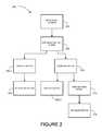
- FIG. 2is a block diagram illustrating an example embodiment of a detection system
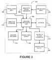
- FIG. 3is a block diagram of an example encoder
- FIG. 4is a block diagram of an example optical detector
- FIG. 5is a block diagram of an example inline detector
- FIG. 6is a flowchart illustrating a method, in accordance with an example embodiment, for encoding a content signal
- FIG. 7is a flowchart illustrating a method, in accordance with an example embodiment, for single pattern detection and identification
- FIG. 8is a flowchart illustrating a method, in accordance with an example embodiment, for multiple pattern detection and identification
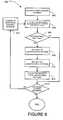
- FIG. 9is a flowchart illustrating a method, in accordance with an example embodiment, for message detection with multiple patterns
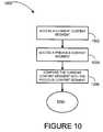
- FIG. 10is a flowchart illustrating a method, in accordance with an example embodiment, for determining pattern format by comparison
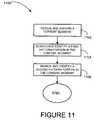
- FIG. 11is a flowchart illustrating a method, in accordance with an example embodiment, for determining pattern format by image recognition
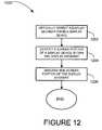
- FIG. 12is a flowchart illustrating a method, in accordance with an example embodiment, for accessing a content segment
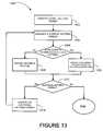
- FIG. 13is a flowchart illustrating a method, in accordance with an example embodiment, for extracting an encoded pattern
- FIG. 14is a block diagram diagrammatic representation of machine in the example form of a computer system within which a set of instructions, for causing the machine to perform any one or more of the methodologies discussed herein, may be executed.
- Example methods and systems for pattern-based encoding and detectionare described.
- numerous specific detailsare set forth in order to provide a thorough understanding of example embodiments. It will be evident, however, to one skilled in the art that the present invention may be practiced without these specific details
- the encoding system 100may transmit a content signal 104 from a signal source 102 to an encoder 106 .
- the content signal 104may include a sequence of images and optionally associated audio.
- Examples of the content signal 104include standard definition (SD) and/or high definition (HD) content signals in NTSC (National Television Standards Committee), PAL (Phase Alternation Line), SECAM (Systeme Electronique Couleur Avec Memoire), a MPEG (Moving Picture Experts Group) signal, a sequence of JPEGs (Joint Photographic Experts Group) sequence of bitmaps, or other signal formats that transport a sequence of images. It may be appreciated that the form of the content signal 104 may be modified to enable implementations involving the content signals 104 of various formats and resolutions.
- the signal source 102may be a unit that is capable of transmitting and/or reproducing a sequence of images electrically in the form of the content signal 104 .
- Examples of the signal source 102include a professional grade video tape player with a video tape, a camcorder, a video file server, a computer with an output port and a digital versatile disc (DVD) player with a DVD disc, and the like.
- An example embodiment of the encoder 106is described in greater detail below.
- the operator 108may interact with the encoder 106 to control its operation to encode the content signal 104 with a message (e.g., an encoded message) defined in the form of one or more identification patterns 110 , thereby producing an encoded content signal 112 that may be provided to a broadcast source 114 .
- the operator 108may include a person that interacts with the encoder 106 through the use of a computer or other electronic control device.
- the operator 108may consist entirely of computer hardware and/or software, or other electronic control device that directs operation of the encoder 106 in an automated manner.
- the identification pattern 110may be in the form of a bar code.
- the bar codemay be one-dimensional such as a UPC bar code.
- the bar codemay be multi-dimensional (e.g., two-dimensional bar codes such as an Aztec code, Data Matrix, Dataglyph, MaxiCode, PDF417, QR Code, Ultra Code or UCC RSS-2D bar code).
- Other machine readable representations of data in a visual formmay also be used.
- the identification pattern 110may include one or more bar codes. Other symbols and shapes that can be matched and interpreted may also be used as the identification pattern 110 .
- the encoded content signal 112may be provided to the broadcast source 114 for distribution and/or transmission to an end-user (e.g., a viewer) who may view the content associated with encoded content signal 112 .
- the broadcast source 114may deliver content to one or more viewers in formats including analog and/or digital video by storage medium such as DVD, tapes, and other fixed medium and/or by transmission sources such as television broadcast stations, cable, satellite, wireless and Internet sources that broadcast or otherwise transmit content.
- the detection system 200may transmit an encoded content signal 204 to a display device 206 . 1 or an inline detector 210 .
- the encoded content signal 204may be the encoded content signal 112 (see FIG. 1 ).
- the inline detector 210may receive the encoded content signal 204 electrically from the broadcast source 202 , and thereafter may transmit a transmission signal 212 to a signaled device 214 and optionally provide the encoded content signal 204 to a display device 206 . 2 .
- An example embodiment of the inline detector 210is described in greater detail below.
- the inline detector 210may detect the identification pattern 110 (see FIG. 1 ) encoded within the encoded content signal 204 and transmit a message to the signaled device 214 by use of the transmission signal 212 and optionally provide the encoded content signal 204 to a display device 206 . 2 .
- the transmission signal 212may include a wireless radio frequency, infrared and direct wire connection, and other transmission mediums by which signals may be sent and received.
- the signaled device 214may be a device capable of receiving and processing the message transmitted by the transmission signal 212 .
- the messagemay be a trigger for an event on the signaled device 214 .
- the eventsmay include a promotional opportunity, electronic game play enhancement, sound and/or lights on the signaled device 214 may operate, and the like.
- the messagemay provide an indication of a presence of rights associated with the encoded content signal 204 , provide a promotional opportunity, provide electronic game play enhancement, be a uniform resource locator (URL), be an electronic coupon, provide an index to a database, or the like.
- multiple messagesmay be encoded in the encoded content signal 204 .
- the message once receivedmay be utilized.
- the messagemay be used to trigger the event on the signaled device 214 , verify the presence of rights associated with encoded content signal 204 , enable use of a promotional opportunity, enhance an electronic game, and the like.
- the signaled device 214may be a DVD recorder, PC based or consumer electronic based personal video recorder, and/or other devices capable of recording content to be viewed or any device that performs an analog to digital conversion for the purpose of storing, redistributing and/or subsequently outputting or otherwise making the encoded content signal 204 available.
- the signaled device 214may be a hand-held device such as a portable gaming device, a mobile telephone, and/or a personal digital assistant (PDA).
- PDApersonal digital assistant
- the signaled device 214may be made integral with the inline detector device 210 .
- An optical detector 208may receive and process the identification pattern 110 from a display device 206 . 1 to obtain the message. An implementation of the optical detector 208 is described in greater detail below.
- the display devices 206 . 1 , 206 . 2may receive the encoded content signal 204 directly from the broadcast source 204 and/or indirectly through the inline detector 210 .
- the display devices 206 . 1 , 206 . 2may be devices capable of presenting the content signal 104 (see FIG. 1 ) and/or the encoded content signal 112 , 204 to a viewer such as of an analog or digital television, but may additionally or alternatively include a device capable of recording the content signal 104 and/or the encoded content signal 112 , 204 such as a digital video recorder.
- Examples of the display devices 206 . 1 , 206 . 2may include projection televisions, plasma televisions, liquid crystal displays (LCD), personal computer (PC) screens, digital light processing (DLP), stadium displays, devices that may incorporate displays such as toys and personal electronics, and the like.
- an encoder 300according to an example embodiment is illustrated.
- the components and/or functionally of the encoder 106may include the components and/or functionally of the encoder 300 .
- the encoder 300may be a computer with specialized input/output hardware, an application specific circuit, programmable hardware, an integrated circuit, an application software unit, and/or other hardware and/or software combinations.
- the encoder processing unit 302may include a central processing unit (CPU).
- the encoder 300may include an encoder processing unit 302 that may direct operation of the encoder 300 .
- the encoder processing unit 302may alter attributes of the content signal 104 to produce the encoded content signal 112 , 204 containing the identification pattern 110 (see FIGS. 1 and 2 ).
- a digital video input 304may be in operative association with the encoder processing unit 302 and may be capable of receiving the content signal 104 from the signal source 102 (see FIG. 1 ).
- the encoder 300may additionally or alternatively receive an analog content signal 104 through an analog video input 306 and an analog-to-digital converter 308 .
- the analog-to-digital converter 308may digitize the analog content signal 104 such that a digitized content signal 104 may be provided to the encoder processing unit 302 .
- An operator interface 310may be operatively associated with encoder processing unit 302 and may provide the encoder processing unit 302 with instructions including where, when and/or at what magnitude the encoder 300 should selectively raise and/or lower a value (e.g., the luminance and/or chrominance level of content lines of the content signal 104 or portions thereof at the direction of the operator 108 of FIG. 1 ).
- the instructionsmay be obtained by the operator interface 310 through a port and/or an integrated operator interface.
- other device interconnects of the encoder 300may be used including a serial port, universal serial bus (USB), “Firewire” protocol (IEEE 1394), and/or various wireless protocols.
- responsibilities of the operator 108 and/or the operator interface 310may be partially or wholly integrated with the encoder software 314 such that the encoder 300 may operate in an automated manner.
- the encoder processing unit 302may store the luminance information (and/or chrominance information as desired) of the content signal 104 in a storage 312 .
- the storage 312may have the capacity to hold and retain signals (e.g., fields of the content signal 104 and corresponding audio signals) in a digital form for access (e.g., by the encoder processing unit 302 ).
- the storage 312may be primary storage and/or secondary storage, and may include memory.
- the encoder 300may send the resulting encoded content signal 112 , 204 in a digital format through a digital video output 316 , or in an analog format by converting the resulting digital signal with a digital-to-analog converter 318 and outputting the encoded content signal 112 , 204 by an analog video output 320 .
- the encoder 300need not include both the digital video input 304 and the digital video output 316 in combination with the analog video input 306 and the analog video output 320 . Rather, a lesser number of the inputs 304 , 306 and/or the outputs 316 , 320 may be included. In addition, other forms of inputting and/or outputting the content signal 104 (and the encoded content signal 112 , 204 ) may be interchangeably used.
- components used by the encoder 300may differ when the functionality of the encoder 300 is included in a pre-existing device as opposed to a stand alone custom device.
- the encoder 300may include varying degrees of hardware and/or software, as various components may interchangeably be used.
- an optical detector 400according to an example embodiment is illustrated.
- the components and/or functionally of the optical detector 208may include the components and/or functionally of the optical detector 400 .
- the optical detector 400may include an imaging sensor device 406 operatively associated with an analog-to-digital converter 408 and a detector processing unit 402 to optically detect the encoded content signal 112 , 204 (e.g., as may be presented on the display device 206 . 1 , 206 . 2 of FIG. 2 ).
- the imaging sensor device 406may be a CMOS (Complimentary Metal Oxide Semiconductor) imaging sensor, while in another example embodiment the imaging sensor device may be a CCD (Charge-Coupled Device) imaging sensor.
- the imaging sensor device 406may be in focus to detect motion on the display device 206 . 1 , 206 . 2 relative to background.
- the detector processing unit 402may be an application specific circuit, programmable hardware, integrated circuit, application software unit, and/or hardware and/or software combination.
- the detector processing unit 402may store the values (e.g., luminance, chrominance, or luminance and chrominance) of the encoded content signal 112 , 204 in a storage 412 and may detect content lines and/or portions thereof that have increased or decreased value levels.
- the detector processing unit 402may process the encoded content signal 112 , 204 to detect the identification pattern 110 (see FIG. 1 ).
- An optional optical filter 404may be placed over a lens of the imaging sensor device 406 to enhance the readability of the identification pattern 110 contained within the encoded content signal 112 , 204 .
- the optical filter 404may be a red filter, but other filters may also be used
- a signal output 414may be electrically coupled to the detector processing unit 402 and provide a data output for the message transmitted by the identification pattern 110 and/or data associated with the message after further processing by the optical detector 400 .
- the data outputmay be one-bit data and/or multi-bit data.
- An optional visual indicator 416may be further electrically coupled to the detector processing unit 402 and may provide a visual and/or audio feedback to a user of the optical detector 400 , which may by way of example include notice of availability of promotional opportunities based on the receipt of the message.
- the detector processing unit 402may store the values of the encoded content signal 112 , 204 in the storage 412 and detect content lines and/or portions thereof that have increased or decreased values levels.
- the functionality of the storage 412may include the functionality of the storage 312 (see FIG. 3 ). An embodiment of a detection scheme is described in greater detail below.
- an inline detector 500according to an example embodiment is illustrated.
- the components and/or functionally of the inline detector 210may include the components and/or functionally of the optical detector 500 .
- the inline detector 500may include an analog video input 506 to receive the encoded content signal 112 , 204 from the broadcast source 202 when the encoded content signal 112 , 204 is an analog format, and a digital video input 504 for receiving the encoded content signal 112 , 204 when the encoded content signal 112 , 204 is in a digital format (see FIGS. 1 and 2 ).
- the digital video input 504may directly pass the encoded content signal 112 , 204 to a detector processing unit 502
- the analog video input 506may digitize the encoded content signal 112 , 204 by use of an analog-to-digital converter 508 before passing the encoded content signal 112 , 204 to the detector processing unit 502 .
- other configurations of inputs and/or outputs of encoded content signal 112 , 204may also be used.
- the detector processing unit 502may process the encoded content signal 112 , 204 to detect the identification pattern 110 (see FIG. 1 ).
- the detector processing unit 502may be an application specific circuit, programmable hardware, integrated circuit, application software unit, and/or hardware and/or software combination are also contemplated.
- the detector processing unit 502may store the values (e.g., luminance, chrominance, or luminance and chrominance) of the encoded content signal 112 , 204 in a storage 510 and detect content lines and/or portions thereof that have increased or decreased value levels, which may represent an encoded signal.
- a storage 510may store the values (e.g., luminance, chrominance, or luminance and chrominance) of the encoded content signal 112 , 204 in a storage 510 and detect content lines and/or portions thereof that have increased or decreased value levels, which may represent an encoded signal.
- the message transmitted by the identification pattern 110may be transferred from the inline detector 500 to the signaled device 214 (see FIG. 2 ) by a signal output 514 .
- the inline detector 500may optionally output the encoded content signal 112 , 204 in a digital format through a digital video output 516 and/or in an analog format by first converting the encoded content signal 112 , 204 from the digital format to the analog format by use of an digital-to-analog converter 518 , and then outputting the encoded content signal 112 , 204 through an analog video output 520 .
- the inline detector 500need not output the encoded content signal 112 , 204 unless otherwise desired.
- a method 600 for encoding a content signal 104(see FIG. 1 ) according to an example embodiment is illustrated.
- the method 600may be performed on the encoder 106 , 300 (see FIGS. 1 and 3 ).
- the content signal 104may be accessed from the signal source 102 (see FIG. 1 ) at block 602 .
- the instructionsmay be received from the operator 108 at block 602 .
- the encoder 106 , 300may obtain the content signal 104 at block 602 and receive the operator instructions at block 604 .
- the operator instructionsmay instruct the encoder 106 , 300 to encode one or more identification patterns 110 over a series of two or more consecutive content segments of the content signal 104 .
- the operator instructionsmay direct the encoder 106 , 300 to encode one or more identification patterns 110 within one or more content segments, then not encode one or more content segments, then again encode one or more content segments.
- Other schemes of designating content segments for encoding by operator instructionsmay also be used.
- the operations of block 602 and block 604may occur concurrently or near-concurrently, while in another embodiment the operations of block 602 may be completed prior to starting the operations at block 604 .
- a first content segment of the content signal 104may be accessed at block 606 .
- the content segmentmay be a frame and/or a field of the content signal.
- the first content segmentmay be identified as a current content segment (e.g., when the content signal 104 is stored on encoder 106 , 300 prior to encoding) and/or obtained as the current content segment (e.g., when the content signal 104 is being read a content segment at a time from the signal source 102 ).
- the operations at block 610may be performed by superimposing the identification pattern 110 into the current content segment and/or by inserting the identification pattern 110 into the current content segment.
- the identification pattern 110 encoded at block 610may be encoded in a substantially invisible way (e.g., the identification pattern 110 is not normally visually detectable by a typical viewer).
- an amount of adjustment to the values (e.g., luminance, chrominance or luminance and chrominance) by using a modulation method for the encoding method 600may be small enough so as to make the identification pattern 110 substantially invisible within the encoded content signal 112 , 204 .
- the one or more content segments selected for encodingmay enable the identification pattern 110 to be substantially invisible within the encoded content signal 112 , 204 .
- the identification pattern 110may be encoded over an entire portion of the one or more particular content segments selected for encoding, while in another embodiment the identification pattern 110 may be encoded over a lesser portion of the one or more particular content segments selected for encoding.
- the lesser portion of the one or more content segments selected for encodingmay change its size, location, or size and location within the identification pattern 110 selected for encoding.
- the method 600may proceed to block 612 .
- the current content segmentmay be outputted at block 612 .
- the encodermay provide the current content segment to the broadcast source 114 (see FIG. 1 ) at block 612 .
- a determinationmay be made as to whether there is another content segment in the content signal 104 . If there is another content segment, another content segment may be accessed as the current content segment at block 616 and the method 600 may return to decision block 608 . If there is not another content segment at decision block 608 , the method 600 may terminate.
- the encoded content signal 112 , 204may be outputted from the encoder 106 , 300 to the broadcast source 114 in addition to or instead of outputting each content segment at block 612 .
- a method 700 for single encoded pattern detection and identificationis illustrated.
- the method 700may be performed on the optical detector 208 , 400 and/or the inline detector 210 , 500 (see FIGS. 2 , 4 and 5 ).
- a first content segment of the encoded content signal 112may be obtained at block 702 . Thereafter, a pattern format determination may be performed on a current content segment at block 704 .
- the pattern format determinationmay identify whether the current content segment includes a pattern format (e.g., indicia that the current content segment includes the identification pattern 110 of FIG. 1 ).
- the pattern formatmay be identified when segment differences of the content segment appear to be in a format of a pattern, when a first pattern portion and a second pattern portion are located in the content segment, and the like. Example embodiments of performing pattern format determinations are described in greater detail below.
- the identification pattern 110may be decoded at block 710 to obtain a message.
- the decoding at block 710may include translating the identification pattern 110 into the message, matching the identification pattern 110 to a known pattern (e.g., a prestored on a detection device 208 , 210 , 400 , 500 ) to obtain the message, and the like.
- the method 700may then utilize the message at block 712 .
- the method 700may determine whether there is an additional content segment at decision block 714 . If there is an additional content segment, the method 700 may obtain an additional content segment at block 716 and return to block 714 . If there are no additional content segments at decision block 714 or after completing the operations at block 712 , the method 700 may terminate.
- a method 800 for multiple encoded patterns detection and identificationis illustrated.
- the method 800may be performed on the optical detector 208 , 400 and/or the inline detector 210 , 500 (see FIGS. 2 , 4 and 5 ).
- a first content segment of encoded content signal 112may be obtained at block 802 . Thereafter, a pattern format determination may be performed on a current content segment at block 804 . For example, pattern format determination may determine whether the current content segment includes the identification pattern 110 .
- the identification pattern 110may be decoded at block 810 to obtain a message.
- the decoding at block 810may include translating the identification pattern 110 into the message, matching the identification pattern 110 to a known pattern (e.g., a prestored on a detection device 208 , 210 , 400 , 500 ) to obtain the message, and the like.
- the method 800may then utilize the message at block 812 .
- the method 800may determine whether there is an additional content segment at decision block 814 . If there is an additional content segment, the method 800 may obtain an additional content segment at block 816 and return to block 814 . If there are no additional content segments at decision block 814 , the method 800 may terminate.
- the method 800may be performed on the optical detector 208 , 400 and/or the inline detector 210 , 500 (see FIGS. 2 , 4 and 5 ).
- a starter messagemay be obtained at block 902 .
- the starter messagemay be obtained by performing the method 700 (see FIG. 7 ).
- the starter messagemay indicate a number of patterns to be received to indicate an entire message.
- An additional content segment from the encoded content signal 112 , 204may be accessed at block 904 . Thereafter, a pattern format determination may be performed on a current content segment at block 906 . For example, pattern format determination may determine whether the current content segment includes the identification pattern 110 .
- the identification pattern 110may be decoded at block 912 to obtain a portion of a message.
- the decoding at block 912may include translating the identification pattern 110 into a portion of the message, matching the identification pattern 110 to a known pattern (e.g., a prestored on a detection device 208 , 210 , 400 , 500 ) to obtain a portion of the message, and the like.
- the method 900may determine whether the message is complete (e.g., all portions of the message have been received). If the message is complete, the message may be utilized at block 922 . If the entire message has not been received at decision block 916 or if the pattern format is not identified at decision block 908 , the method 900 may proceed to decision block 918 .
- the method 900may determine at decision block 918 whether an additional content segment is available. If another content segment is available, the method 900 may return to block 904 . If another content segment is not available at decision block 918 , an error routine may be performed at block 920 . After completion of the operations at block 920 or block 922 , the method 900 may terminate.
- a method 1000 for determining pattern format by comparisonis illustrated.
- the method 1000may be performed at block 704 , block 804 , and/or block 906 (see FIGS. 7-9 ).
- a current content segment of the encoded content signal 112 , 204may be accessed at block 1002 .
- a previous content segment of the encoded content signal 112 , 204may be accessed at block 1004 .
- the method 1000may compare the current content segment with the previous content segment at block 1006 to determine whether the current content segment is in the pattern format. For example, the comparison may be by subtracting the previous content segment from the current content segment, where a resulting signal may be the encoded pattern. Upon completion of the operations at block 1006 , the method 1000 may terminate.
- a method 1100 for determining pattern format by image recognitionis illustrated.
- the method 1100may be performed at block 704 , block 804 , and/or block 906 (see FIGS. 7-9 ).
- a content segmentmay be reviewed and discerned at block 1102 .
- reviewing and discerning the content segmentmay include the imaging sensor device 460 (see FIG. 4 ) searching for minor variations among pixels of the content segment to determine if a pattern is present in the content segment.
- the method 1100may search for and identify a first pattern portion in the content segment at block 1104 .
- the first pattern portionmay include a horizontal bar (e.g., a bottom bar) and a vertical bar (e.g., a far left bar) of a square.
- the method 1100may search for and identify a second pattern portion in the content segment at block 1106 .
- the second pattern portionmay include the pattern contained in part by the horizontal bar and the vertical bar of the square.
- the pattern formatmay be identified if the first pattern portion and the second pattern portion are identified in the content segment.
- a method 1200 for accessing a content segmentis illustrated.
- the method 1100may be performed at block 702 , block 716 , block 802 , block 816 , and/or block 904 (see FIGS. 7-9 ).
- a display segmentmay be optically detected from the display device 206 . 1 at block 1202 .
- the display segmentmay be optically detected by taking a picture directed towards a screen of the display device 206 . 1 with the imaging sensor 406 of the optical detector 400 .
- a screen portion of the display device 206 . 1may be identified within the display segment at block 1204 . Thereafter, a non-screen portion of the display segment may be discarded such that a remaining portion of the detected segment is the content segment. Upon completion of the operations at block 1206 , the method 1200 may terminate.
- a method 1300 for extracting the identification pattern 110(see FIG. 1 ) according to an example embodiment is illustrated.
- the method 1300may be performed at block 708 , block 808 and/or block 910 (see FIGS. 7-9 ).
- a first pattern formatmay be identified in a content segment at block 1302 .
- a current pattern formatmay be enhanced at block 1304 .
- the enhancement performed at block 1302may include adopting a threshold by which pixels above the threshold are made black and pixels below the threshold are made white.
- Other enhancements that may enhance contrast of the current pattern formate.g., such that the detector 208 , 210 of FIG. 2 may be able to more easily decode the one or more identification patterns 110 ) may also be used.
- the method 1300may determine whether the current pattern format is a valid pattern.
- the current pattern formatmay be valid when it matches one or more prestored patterns and/or when the current pattern format is a valid bar code.
- the method 1300may identify the current pattern format as an encoded pattern for further processing. If the current pattern format is determined not to be valid (e.g., invalid) at decision block 1308 , the method 1300 may initiate an error routine.
- the error routinemay include dumping data and/or storing the data for analysis purposes.
- the method 1300may determine whether there is another pattern format present in the content segment. If there is another pattern format present in the content segment, another pattern format may be identified at block 1314 and the method 1300 may return to block 1304 . If there is not another pattern formats at decision block 1312 , the method 1300 may terminate.
- FIG. 14shows a diagrammatic representation of machine in the exemplary form of a computer system 1400 within which a set of instructions, for causing the machine to perform any one or more of the methodologies discussed herein, may be executed.
- the machineoperates as a standalone device or may be connected (e.g., networked) to other machines.
- the machinemay operate in the capacity of a server or a client machine in server-client network environment, or as a peer machine in a peer-to-peer (or distributed) network environment.
- the machinemay be a personal computer (PC), a tablet PC, a set-top box (STB), a television, a Personal Digital Assistant (PDA), a cellular telephone, a portable music player (e.g., a portable hard drive audio device such as an MP3 player), a car audio device, a web appliance, a network router, switch or bridge, or any machine capable of executing a set of instructions (sequential or otherwise) that specify actions to be taken by that machine.
- PCpersonal computer
- PDAPersonal Digital Assistant
- portable music playere.g., a portable hard drive audio device such as an MP3 player
- car audio devicee.g., a web appliance, a network router, switch or bridge, or any machine capable of executing a set of instructions (sequential or otherwise) that specify actions to be taken by that machine.
- the term “machine”shall also be taken to include any collection of machines that individually or jointly execute a set (or multiple sets) of instructions to perform any one or more of the methodologies discussed
- the exemplary computer system 1400includes a processor 1402 (e.g., a central processing unit (CPU) a graphics processing unit (GPU) or both), a main memory 1404 and a static memory 1406 , which communicate with each other via a bus 1408 .
- the processor 1402may represent a central processing unit of any type of architecture, such as a CISC (Complex Instruction Set Computing), RISC (Reduced Instruction Set Computing), VLIW (Very Long Instruction Word), or a hybrid architecture, although any appropriate processor may be used.
- the processor 1402may execute instructions and includes that portion of the computer system 1400 that controls the operation of the entire computer system 1400 .
- the computer system 1400may further include a video display unit 1410 (e.g., a liquid crystal display (LCD) or a cathode ray tube (CRT)).
- the computer system 1400also includes an alphanumeric input device 1412 (e.g., a keyboard), a cursor control device 1414 (e.g., a mouse), a disk drive unit 1416 , a signal generation device 1418 (e.g., a speaker) and a network interface device 1420 .
- a video display unit 1410e.g., a liquid crystal display (LCD) or a cathode ray tube (CRT)
- the computer system 1400also includes an alphanumeric input device 1412 (e.g., a keyboard), a cursor control device 1414 (e.g., a mouse), a disk drive unit 1416 , a signal generation device 1418 (e.g., a speaker) and a network interface device 1420 .
- the cursor control device 1414may be a keyboard, mouse or other pointing device, trackball, touchpad, touch screen, keypad, microphone, voice recognition device, or any other appropriate mechanism for the user to input data to the computer 1400 and manipulate the user interface previously discussed. Although only one input device 1414 is shown, in another embodiment any number and type of input devices may be present.
- the disk drive unit 1416includes a machine-readable medium 1422 on which is stored one or more sets of instructions (e.g., software 1424 ) embodying any one or more of the methodologies or functions described herein.
- the software 1424may also reside, completely or at least partially, within the main memory 1404 and/or within the processor 1402 during execution thereof by the computer system 1400 , the main memory 1404 and the processor 1402 also constituting machine-readable media.
- the software 1424may further be transmitted or received over a network 1426 via network interface device 1430 .
- the network 1426may be any suitable network and may support any appropriate protocol suitable for communication to the computer system 1400 .
- the network 1426may support wireless communications.
- the network 1426may support hard-wired communications, such as a telephone line or cable.
- the network 1426may support the Ethernet IEEE (Institute of Electrical and Electronics Engineers) 802.3x specification.
- the network 1426may be the Internet and may support IP (Internet Protocol).
- the network 1426may be a local area network (LAN) or a wide area network (WAN).
- the network 1426may be a hotspot service provider network.
- the network 1426may be an intranet. In another embodiment, the network 1426 may be a GPRS (General Packet Radio Service) network. In another embodiment, the network 1426 may be any appropriate cellular data network or cell-based radio network technology. In another embodiment, the network 1426 may be an IEEE 802.11 wireless network. In still another embodiment, the network 1426 may be any suitable network or combination of networks. Although one network 1426 is shown, in other embodiments any number of networks (of the same or different types) may be present.
- GPRSGeneral Packet Radio Service
- machine-readable medium 1422is shown in an exemplary embodiment to be a single medium, the term “machine-readable medium” should be taken to include a single medium or multiple media (e.g., a centralized or distributed database, and/or associated caches and servers) that store the one or more sets of instructions.
- the term “machine-readable medium”shall also be taken to include any medium that is capable of storing, encoding or carrying a set of instructions for execution by the machine and that cause the machine to perform any one or more of the methodologies of the present invention.
- the term “machine-readable medium”shall accordingly be taken to include, but not be limited to, solid-state memories, optical and magnetic media, and carrier wave signals.
- the computer system 1400may be implemented using any suitable hardware and/or software, such as a personal computer or other electronic computing device. Encoders, detectors, portable computers, laptop or notebook computers, PDAs (Personal Digital Assistants), pocket computers, appliances, telephones, and mainframe computers are examples of other possible configurations of the computer system 1400 .
- Encoders, detectors, portable computers, laptop or notebook computers, PDAs (Personal Digital Assistants), pocket computers, appliances, telephones, and mainframe computersare examples of other possible configurations of the computer system 1400 .
- other peripheral devicessuch as audio adapters or chip programming devices, such as EPROM (Erasable Programmable Read-Only Memory) programming devices may be used in addition to, or in place of, the hardware already depicted.
- EPROMErasable Programmable Read-Only Memory
Landscapes
- Engineering & Computer Science (AREA)
- Multimedia (AREA)
- Signal Processing (AREA)
- Computer Security & Cryptography (AREA)
- Compression Or Coding Systems Of Tv Signals (AREA)
Abstract
Description
Claims (19)
Priority Applications (1)
| Application Number | Priority Date | Filing Date | Title |
|---|---|---|---|
| US11/532,835US7974435B2 (en) | 2005-09-16 | 2006-09-18 | Pattern-based encoding and detection |
Applications Claiming Priority (2)
| Application Number | Priority Date | Filing Date | Title |
|---|---|---|---|
| US71791405P | 2005-09-16 | 2005-09-16 | |
| US11/532,835US7974435B2 (en) | 2005-09-16 | 2006-09-18 | Pattern-based encoding and detection |
Publications (2)
| Publication Number | Publication Date |
|---|---|
| US20070071322A1 US20070071322A1 (en) | 2007-03-29 |
| US7974435B2true US7974435B2 (en) | 2011-07-05 |
Family
ID=37894027
Family Applications (1)
| Application Number | Title | Priority Date | Filing Date |
|---|---|---|---|
| US11/532,835Active2029-08-27US7974435B2 (en) | 2005-09-16 | 2006-09-18 | Pattern-based encoding and detection |
Country Status (1)
| Country | Link |
|---|---|
| US (1) | US7974435B2 (en) |
Cited By (4)
| Publication number | Priority date | Publication date | Assignee | Title |
|---|---|---|---|---|
| US20090028453A1 (en)* | 2007-07-27 | 2009-01-29 | Hewlett-Packard Development Company, L.P. | Content Encoder and Decoder and Methods of Encoding and Decoding Content |
| US20090312105A1 (en)* | 2007-10-31 | 2009-12-17 | Koplar Edward J | Method and system for encoded information processing |
| US8936194B1 (en) | 2013-03-15 | 2015-01-20 | Wunderlich-Malec Engineering, Inc. | Methods and systems for using two-dimensional matrix codes associated with panel component and equipment information and quality control |
| US20160104310A1 (en)* | 2013-06-28 | 2016-04-14 | Schneider Electric Usa Inc. | Systems and methods of blending machine-readable and human-readable elements on a display |
Families Citing this family (5)
| Publication number | Priority date | Publication date | Assignee | Title |
|---|---|---|---|---|
| US7626635B2 (en)* | 2003-04-04 | 2009-12-01 | Koplar Interactive Systems International, L.L.C. | Method and system of detecting signal presence from a video signal presented on a digital display device |
| US7974438B2 (en)* | 2006-12-11 | 2011-07-05 | Koplar Interactive Systems International, Llc | Spatial data encoding and decoding |
| US8320676B2 (en)* | 2008-01-31 | 2012-11-27 | International Business Machines Corporation | Method for configuring camera-equipped electronic devices using an encoded mark |
| US9479812B2 (en)* | 2009-06-05 | 2016-10-25 | Time Warner Cable Enterprises Llc | User selection of software components in a television set-top box |
| US11553026B2 (en)* | 2019-05-27 | 2023-01-10 | International Business Machines Corporation | Regulating content associated with a streaming platform |
Citations (59)
| Publication number | Priority date | Publication date | Assignee | Title |
|---|---|---|---|---|
| US4807031A (en) | 1987-10-20 | 1989-02-21 | Interactive Systems, Incorporated | Interactive video method and apparatus |
| US5305104A (en) | 1992-07-27 | 1994-04-19 | The Trustees Of Columbia University In The City Of New York | Digitally assisted motion compensated deinterlacing for enhanced definition television |
| US5521984A (en)* | 1993-06-10 | 1996-05-28 | Verification Technologies, Inc. | System for registration, identification and verification of items utilizing unique intrinsic features |
| US5594493A (en) | 1994-01-19 | 1997-01-14 | Nemirofsky; Frank R. | Television signal activated interactive smart card system |
| US5644363A (en) | 1995-03-24 | 1997-07-01 | The Advanced Learning Corp. | Apparatus for superimposing visual subliminal instructional materials on a video signal |
| US5880769A (en) | 1994-01-19 | 1999-03-09 | Smarttv Co. | Interactive smart card system for integrating the provision of remote and local services |
| EP0957448A2 (en) | 1998-05-15 | 1999-11-17 | PSC Scanning, Inc. | Optical code reader mouse |
| WO1999064980A1 (en) | 1998-06-12 | 1999-12-16 | Symbol Technologies, Inc. | Imaging engine and method for code readers |
| US6094228A (en) | 1997-10-28 | 2000-07-25 | Ciardullo; Daniel Andrew | Method for transmitting data on viewable portion of a video signal |
| US6215526B1 (en) | 1998-11-06 | 2001-04-10 | Tivo, Inc. | Analog video tagging and encoding system |
| US20010009867A1 (en)* | 2000-01-20 | 2001-07-26 | Square Co., Ltd. | Game system for providing video game situation-solving information online |
| US20010017932A1 (en)* | 1998-08-22 | 2001-08-30 | Chang Kenneth H.P. | Encoding and recording a message within an image |
| US6285774B1 (en)* | 1998-06-08 | 2001-09-04 | Digital Video Express, L.P. | System and methodology for tracing to a source of unauthorized copying of prerecorded proprietary material, such as movies |
| US20020016750A1 (en) | 2000-06-20 | 2002-02-07 | Olivier Attia | System and method for scan-based input, storage and retrieval of information over an interactive communication network |
| US6370275B1 (en) | 1997-10-09 | 2002-04-09 | Thomson Multimedia | Process and device for scanning a plasma panel |
| US6404440B1 (en) | 1997-04-25 | 2002-06-11 | Thomson Multimedia | Process and device for rotating-code addressing for plasma displays |
| US20020080271A1 (en)* | 2000-11-08 | 2002-06-27 | Jan Eveleens | Method and device communicating a command |
| US20020112250A1 (en) | 2000-04-07 | 2002-08-15 | Koplar Edward J. | Universal methods and device for hand-held promotional opportunities |
| US6449379B1 (en) | 1993-11-18 | 2002-09-10 | Digimarc Corporation | Video steganography methods avoiding introduction of fixed pattern noise |
| US6473804B1 (en)* | 1999-01-15 | 2002-10-29 | Grischa Corporation | System for indexical triggers in enhanced video productions by redirecting request to newly generated URI based on extracted parameter of first URI |
| US20020183102A1 (en) | 2001-04-21 | 2002-12-05 | Withers James G. | RBDS method and device for processing promotional opportunities |
| US6604682B2 (en) | 2000-04-06 | 2003-08-12 | Seiko Epson Corporation | Method of and apparatus for reading a two-dimensional bar code symbol and data storage medium |
| US20030189731A1 (en)* | 2002-04-06 | 2003-10-09 | Chang Kenneth H.P. | Print user interface system and its applications |
| US6661905B1 (en) | 1998-03-23 | 2003-12-09 | Koplar Interactive Systems International Llc | Method for transmitting data on a viewable portion of a video signal |
| US20030229900A1 (en)* | 2002-05-10 | 2003-12-11 | Richard Reisman | Method and apparatus for browsing using multiple coordinated device sets |
| US6766956B1 (en) | 2000-06-08 | 2004-07-27 | United Video Properties, Inc. | System and method for using portable device with bar-code scanner |
| US20040262395A1 (en) | 1994-03-04 | 2004-12-30 | Longacre Andrew Jr | Portable autodiscriminating optical reader |
| US20050004844A1 (en) | 2003-04-23 | 2005-01-06 | Olivier Attia | Integrating barcode scanner enabled services in existing e-commerce applications using a floating pop-up web window |
| US20050015311A1 (en) | 2003-07-16 | 2005-01-20 | Didier Frantz | System and method for aggregate online ordering using barcode scanners |
| US20050015310A1 (en) | 2003-07-16 | 2005-01-20 | Didier Frantz | System and method for aggregating and managing client orders using barcode scanning technology |
| US20050011957A1 (en) | 2003-07-16 | 2005-01-20 | Olivier Attia | System and method for decoding and analyzing barcodes using a mobile device |
| US20050033599A1 (en) | 2003-08-05 | 2005-02-10 | Didier Frantz | Printing on-the-fly barcoded documents |
| US20050029354A1 (en) | 2003-08-05 | 2005-02-10 | Didier Frantz | System associating sets of data into one barcode |
| US20050029356A1 (en) | 2003-08-05 | 2005-02-10 | Didier Frantz | Scanner reader Active-X plug-in |
| US20050035206A1 (en) | 2003-08-11 | 2005-02-17 | Olivier Attia | Group average filter algorithm for digital image processing |
| US20050082370A1 (en) | 2003-10-17 | 2005-04-21 | Didier Frantz | System and method for decoding barcodes using digital imaging techniques |
| US20050094031A1 (en) | 2003-10-31 | 2005-05-05 | Tecot Edward M. | Interface strategies for creating and invoking marks |
| US20050121521A1 (en) | 2003-12-04 | 2005-06-09 | Rashmi Ghai | Section based algorithm for image enhancement |
| US20050125301A1 (en) | 2003-12-04 | 2005-06-09 | Ashish Muni | System and method for on the spot purchasing by scanning barcodes from screens with a mobile device |
| US20050246196A1 (en) | 2004-04-28 | 2005-11-03 | Didier Frantz | Real-time behavior monitoring system |
| US20050264694A1 (en) | 2002-08-20 | 2005-12-01 | Optinetix (Israel ) Ltd. | Method and apparatus for transferring data within viewable portion of video signal |
| US20060011728A1 (en) | 2004-07-14 | 2006-01-19 | Didier Frantz | Mobile device gateway providing access to instant information |
| US7025272B2 (en) | 2002-12-18 | 2006-04-11 | Symbol Technologies, Inc. | System and method for auto focusing an optical code reader |
| US20060080556A1 (en) | 1993-11-18 | 2006-04-13 | Rhoads Geoffrey B | Hiding and detecting messages in media signals |
| US20060188128A1 (en) | 1993-11-18 | 2006-08-24 | Rhoads Geoffrey B | Method and System for Managing and Controlling Electronic Media |
| US20060200260A1 (en) | 1991-12-23 | 2006-09-07 | Steven Hoffberg | System and method for intermachine markup language communications |
| US20060236266A1 (en)* | 2005-03-18 | 2006-10-19 | Nokia Corporation | User interface |
| US20060282855A1 (en)* | 2005-05-05 | 2006-12-14 | Digital Display Innovations, Llc | Multiple remote display system |
| US20060287105A1 (en)* | 2005-05-17 | 2006-12-21 | Daniel Willis | Method and system for enhancing video games and video game systems |
| US7167209B2 (en) | 2003-02-07 | 2007-01-23 | Warner Bros. Entertainment, Inc. | Methods for encoding data in an analog video signal such that it survives resolution conversion |
| US20070022437A1 (en)* | 2005-07-19 | 2007-01-25 | David Gerken | Methods and apparatus for providing content and services coordinated with television content |
| US20070230921A1 (en) | 2001-04-05 | 2007-10-04 | Barton James M | Multimedia time warping system |
| US7296747B2 (en) | 2004-04-20 | 2007-11-20 | Michael Rohs | Visual code system for camera-equipped mobile devices and applications thereof |
| US20080030614A1 (en) | 1997-04-07 | 2008-02-07 | Schwab Barry H | Integrated multi-format audio/video production system |
| US20080193023A1 (en) | 2006-12-11 | 2008-08-14 | Koplar Interactive Systems International, L.L.C. | Spatial data encoding and decoding |
| US7502759B2 (en)* | 1999-08-30 | 2009-03-10 | Digimarc Corporation | Digital watermarking methods and related toy and game applications |
| US7567671B2 (en)* | 2005-06-10 | 2009-07-28 | Aniruddha Gupte | Encryption method and apparatus for use in digital distribution system |
| US7570781B2 (en)* | 1999-05-19 | 2009-08-04 | Digimarc Corporation | Embedded data in gaming objects for authentication and association of behavior information |
| US7808554B2 (en)* | 2005-03-18 | 2010-10-05 | Displaymate Technologies Corporation | Automatic and interactive configuration and control of a video system |
Family Cites Families (3)
| Publication number | Priority date | Publication date | Assignee | Title |
|---|---|---|---|---|
| US5616908A (en)* | 1991-09-17 | 1997-04-01 | Metrologic Instruments, Inc. | Automatic countertop laser scanner with flickering laser scanner beam for improved visibility thereof during bar code symbol reading |
| US6627840B2 (en)* | 2001-03-09 | 2003-09-30 | Revelation Technologies, Llc | Method and means for processing butt welds |
| KR100477359B1 (en)* | 2003-04-30 | 2005-03-22 | 주식회사 대우일렉트로닉스 | Holographic rom system |
- 2006
- 2006-09-18USUS11/532,835patent/US7974435B2/enactiveActive
Patent Citations (73)
| Publication number | Priority date | Publication date | Assignee | Title |
|---|---|---|---|---|
| US4807031A (en) | 1987-10-20 | 1989-02-21 | Interactive Systems, Incorporated | Interactive video method and apparatus |
| US20060200260A1 (en) | 1991-12-23 | 2006-09-07 | Steven Hoffberg | System and method for intermachine markup language communications |
| US5305104A (en) | 1992-07-27 | 1994-04-19 | The Trustees Of Columbia University In The City Of New York | Digitally assisted motion compensated deinterlacing for enhanced definition television |
| US5521984A (en)* | 1993-06-10 | 1996-05-28 | Verification Technologies, Inc. | System for registration, identification and verification of items utilizing unique intrinsic features |
| US20060080556A1 (en) | 1993-11-18 | 2006-04-13 | Rhoads Geoffrey B | Hiding and detecting messages in media signals |
| US20060188128A1 (en) | 1993-11-18 | 2006-08-24 | Rhoads Geoffrey B | Method and System for Managing and Controlling Electronic Media |
| US6449379B1 (en) | 1993-11-18 | 2002-09-10 | Digimarc Corporation | Video steganography methods avoiding introduction of fixed pattern noise |
| US5594493A (en) | 1994-01-19 | 1997-01-14 | Nemirofsky; Frank R. | Television signal activated interactive smart card system |
| US5767896A (en) | 1994-01-19 | 1998-06-16 | Smart Tv Llc | Television signal activated interactive smart card system |
| US5880769A (en) | 1994-01-19 | 1999-03-09 | Smarttv Co. | Interactive smart card system for integrating the provision of remote and local services |
| US5907350A (en) | 1994-01-19 | 1999-05-25 | Smart T.V. Llc | Television signal activated interactive smart card system |
| US5953047A (en) | 1994-01-19 | 1999-09-14 | Smart Tv Llc | Television signal activated interactive smart card system |
| US20060175413A1 (en) | 1994-03-04 | 2006-08-10 | Longacre Andrew Jr | Reading apparatus having reprogramming features |
| US20040262395A1 (en) | 1994-03-04 | 2004-12-30 | Longacre Andrew Jr | Portable autodiscriminating optical reader |
| US20040262399A1 (en) | 1994-03-04 | 2004-12-30 | Longacre Andrew Jr | Optical reader comprising illumination assembly and solid state image sensor |
| US5644363A (en) | 1995-03-24 | 1997-07-01 | The Advanced Learning Corp. | Apparatus for superimposing visual subliminal instructional materials on a video signal |
| US20080030614A1 (en) | 1997-04-07 | 2008-02-07 | Schwab Barry H | Integrated multi-format audio/video production system |
| US6404440B1 (en) | 1997-04-25 | 2002-06-11 | Thomson Multimedia | Process and device for rotating-code addressing for plasma displays |
| US6370275B1 (en) | 1997-10-09 | 2002-04-09 | Thomson Multimedia | Process and device for scanning a plasma panel |
| US6229572B1 (en) | 1997-10-28 | 2001-05-08 | Koplar Interactive International, Llc | Method for transmitting data on viewable portion of a video signal |
| US6094228A (en) | 1997-10-28 | 2000-07-25 | Ciardullo; Daniel Andrew | Method for transmitting data on viewable portion of a video signal |
| US6661905B1 (en) | 1998-03-23 | 2003-12-09 | Koplar Interactive Systems International Llc | Method for transmitting data on a viewable portion of a video signal |
| EP0957448A2 (en) | 1998-05-15 | 1999-11-17 | PSC Scanning, Inc. | Optical code reader mouse |
| US6285774B1 (en)* | 1998-06-08 | 2001-09-04 | Digital Video Express, L.P. | System and methodology for tracing to a source of unauthorized copying of prerecorded proprietary material, such as movies |
| WO1999064980A1 (en) | 1998-06-12 | 1999-12-16 | Symbol Technologies, Inc. | Imaging engine and method for code readers |
| US20010017932A1 (en)* | 1998-08-22 | 2001-08-30 | Chang Kenneth H.P. | Encoding and recording a message within an image |
| US6215526B1 (en) | 1998-11-06 | 2001-04-10 | Tivo, Inc. | Analog video tagging and encoding system |
| US6473804B1 (en)* | 1999-01-15 | 2002-10-29 | Grischa Corporation | System for indexical triggers in enhanced video productions by redirecting request to newly generated URI based on extracted parameter of first URI |
| US7570781B2 (en)* | 1999-05-19 | 2009-08-04 | Digimarc Corporation | Embedded data in gaming objects for authentication and association of behavior information |
| US7502759B2 (en)* | 1999-08-30 | 2009-03-10 | Digimarc Corporation | Digital watermarking methods and related toy and game applications |
| US20010009867A1 (en)* | 2000-01-20 | 2001-07-26 | Square Co., Ltd. | Game system for providing video game situation-solving information online |
| US6604682B2 (en) | 2000-04-06 | 2003-08-12 | Seiko Epson Corporation | Method of and apparatus for reading a two-dimensional bar code symbol and data storage medium |
| US20020112250A1 (en) | 2000-04-07 | 2002-08-15 | Koplar Edward J. | Universal methods and device for hand-held promotional opportunities |
| US6766956B1 (en) | 2000-06-08 | 2004-07-27 | United Video Properties, Inc. | System and method for using portable device with bar-code scanner |
| US20020016750A1 (en) | 2000-06-20 | 2002-02-07 | Olivier Attia | System and method for scan-based input, storage and retrieval of information over an interactive communication network |
| US20020080271A1 (en)* | 2000-11-08 | 2002-06-27 | Jan Eveleens | Method and device communicating a command |
| US20070230921A1 (en) | 2001-04-05 | 2007-10-04 | Barton James M | Multimedia time warping system |
| US20020183102A1 (en) | 2001-04-21 | 2002-12-05 | Withers James G. | RBDS method and device for processing promotional opportunities |
| US20030189731A1 (en)* | 2002-04-06 | 2003-10-09 | Chang Kenneth H.P. | Print user interface system and its applications |
| US20030229900A1 (en)* | 2002-05-10 | 2003-12-11 | Richard Reisman | Method and apparatus for browsing using multiple coordinated device sets |
| US20050264694A1 (en) | 2002-08-20 | 2005-12-01 | Optinetix (Israel ) Ltd. | Method and apparatus for transferring data within viewable portion of video signal |
| US7025272B2 (en) | 2002-12-18 | 2006-04-11 | Symbol Technologies, Inc. | System and method for auto focusing an optical code reader |
| US7167209B2 (en) | 2003-02-07 | 2007-01-23 | Warner Bros. Entertainment, Inc. | Methods for encoding data in an analog video signal such that it survives resolution conversion |
| US20050004844A1 (en) | 2003-04-23 | 2005-01-06 | Olivier Attia | Integrating barcode scanner enabled services in existing e-commerce applications using a floating pop-up web window |
| US20050015310A1 (en) | 2003-07-16 | 2005-01-20 | Didier Frantz | System and method for aggregating and managing client orders using barcode scanning technology |
| US7156311B2 (en) | 2003-07-16 | 2007-01-02 | Scanbuy, Inc. | System and method for decoding and analyzing barcodes using a mobile device |
| US20070063050A1 (en) | 2003-07-16 | 2007-03-22 | Scanbuy, Inc. | System and method for decoding and analyzing barcodes using a mobile device |
| US7287696B2 (en) | 2003-07-16 | 2007-10-30 | Scanbuy, Inc. | System and method for decoding and analyzing barcodes using a mobile device |
| US20050011957A1 (en) | 2003-07-16 | 2005-01-20 | Olivier Attia | System and method for decoding and analyzing barcodes using a mobile device |
| US20050015311A1 (en) | 2003-07-16 | 2005-01-20 | Didier Frantz | System and method for aggregate online ordering using barcode scanners |
| US20050033599A1 (en) | 2003-08-05 | 2005-02-10 | Didier Frantz | Printing on-the-fly barcoded documents |
| US20050029354A1 (en) | 2003-08-05 | 2005-02-10 | Didier Frantz | System associating sets of data into one barcode |
| US20050029356A1 (en) | 2003-08-05 | 2005-02-10 | Didier Frantz | Scanner reader Active-X plug-in |
| US20050035206A1 (en) | 2003-08-11 | 2005-02-17 | Olivier Attia | Group average filter algorithm for digital image processing |
| US20060193530A1 (en) | 2003-08-11 | 2006-08-31 | Scanbuy, Inc. | Group average filter algorithm for digital image processing |
| US7242816B2 (en) | 2003-08-11 | 2007-07-10 | Scanbuy, Inc. | Group average filter algorithm for digital image processing |
| US7245780B2 (en) | 2003-08-11 | 2007-07-17 | Scanbuy, Inc. | Group average filter algorithm for digital image processing |
| US20050082370A1 (en) | 2003-10-17 | 2005-04-21 | Didier Frantz | System and method for decoding barcodes using digital imaging techniques |
| US20050094031A1 (en) | 2003-10-31 | 2005-05-05 | Tecot Edward M. | Interface strategies for creating and invoking marks |
| US20050125301A1 (en) | 2003-12-04 | 2005-06-09 | Ashish Muni | System and method for on the spot purchasing by scanning barcodes from screens with a mobile device |
| US7168621B2 (en) | 2003-12-04 | 2007-01-30 | Scanbury, Inc. | Section based algorithm for image enhancement |
| US20050121521A1 (en) | 2003-12-04 | 2005-06-09 | Rashmi Ghai | Section based algorithm for image enhancement |
| US7296747B2 (en) | 2004-04-20 | 2007-11-20 | Michael Rohs | Visual code system for camera-equipped mobile devices and applications thereof |
| US20050246196A1 (en) | 2004-04-28 | 2005-11-03 | Didier Frantz | Real-time behavior monitoring system |
| US7309015B2 (en) | 2004-07-14 | 2007-12-18 | Scanbuy, Inc. | Mobile device gateway providing access to instant information |
| US20060011728A1 (en) | 2004-07-14 | 2006-01-19 | Didier Frantz | Mobile device gateway providing access to instant information |
| US20060236266A1 (en)* | 2005-03-18 | 2006-10-19 | Nokia Corporation | User interface |
| US7808554B2 (en)* | 2005-03-18 | 2010-10-05 | Displaymate Technologies Corporation | Automatic and interactive configuration and control of a video system |
| US20060282855A1 (en)* | 2005-05-05 | 2006-12-14 | Digital Display Innovations, Llc | Multiple remote display system |
| US20060287105A1 (en)* | 2005-05-17 | 2006-12-21 | Daniel Willis | Method and system for enhancing video games and video game systems |
| US7567671B2 (en)* | 2005-06-10 | 2009-07-28 | Aniruddha Gupte | Encryption method and apparatus for use in digital distribution system |
| US20070022437A1 (en)* | 2005-07-19 | 2007-01-25 | David Gerken | Methods and apparatus for providing content and services coordinated with television content |
| US20080193023A1 (en) | 2006-12-11 | 2008-08-14 | Koplar Interactive Systems International, L.L.C. | Spatial data encoding and decoding |
Non-Patent Citations (10)
Cited By (7)
| Publication number | Priority date | Publication date | Assignee | Title |
|---|---|---|---|---|
| US20090028453A1 (en)* | 2007-07-27 | 2009-01-29 | Hewlett-Packard Development Company, L.P. | Content Encoder and Decoder and Methods of Encoding and Decoding Content |
| US9270846B2 (en)* | 2007-07-27 | 2016-02-23 | Hewlett-Packard Development Company, L.P. | Content encoded luminosity modulation |
| US20090312105A1 (en)* | 2007-10-31 | 2009-12-17 | Koplar Edward J | Method and system for encoded information processing |
| US8961324B2 (en)* | 2007-10-31 | 2015-02-24 | Koplar Interactive Systems International, L.L.C. | Method and system for encoded information processing |
| US8936194B1 (en) | 2013-03-15 | 2015-01-20 | Wunderlich-Malec Engineering, Inc. | Methods and systems for using two-dimensional matrix codes associated with panel component and equipment information and quality control |
| US9047279B1 (en) | 2013-03-15 | 2015-06-02 | Wunderlich-Malec Engineering, Inc. | Methods and systems for using two-dimensional matrix codes associated with panel component and equipment information and quality control |
| US20160104310A1 (en)* | 2013-06-28 | 2016-04-14 | Schneider Electric Usa Inc. | Systems and methods of blending machine-readable and human-readable elements on a display |
Also Published As
| Publication number | Publication date |
|---|---|
| US20070071322A1 (en) | 2007-03-29 |
Similar Documents
| Publication | Publication Date | Title |
|---|---|---|
| US7974435B2 (en) | Pattern-based encoding and detection | |
| US8295622B2 (en) | Spatial data encoding and decoding | |
| RU2714103C1 (en) | Methods for encoding, decoding and displaying high-dynamic range images | |
| US20190259124A1 (en) | System and Method of Data Transfer In-Band in Video via Optically Encoded Images | |
| EP2109313B1 (en) | Television receiver and method | |
| US20140294100A1 (en) | Dual channel encoding and detection | |
| CN110365973B (en) | Video detection method and device, electronic equipment and computer readable storage medium | |
| CN110971931A (en) | Video watermark adding method and device, electronic equipment and storage medium | |
| KR20170010378A (en) | Text detection in video | |
| CN103430565A (en) | Synching one or more matrix codes to content related to multimedia presentation | |
| Yang et al. | ARTcode: preserve art and code in any image | |
| CN102156611A (en) | Method and apparatus for creating animation message | |
| WO2020097803A1 (en) | Overlay comment processing method and apparatus, electronic device, and computer-readable storage medium | |
| CN105340285A (en) | Methods, systems, and media for presenting media content using integrated content sources | |
| US20190068987A1 (en) | Systems and Methods for Embedding Metadata into Video Contents | |
| WO2022028177A1 (en) | Information pushing method, video processing method, and device | |
| EP3985989A1 (en) | Detection of modification of an item of content | |
| CN112437289B (en) | Switching time delay obtaining method | |
| CN105100544A (en) | Video information display method and system | |
| US12113993B2 (en) | Video processing method and device | |
| US20080198923A1 (en) | Content signal modulation and decoding | |
| Liu et al. | A camera-based mobile data channel: capacity and analysis | |
| KR20050030711A (en) | Wireless communication terminal and its method for playing multimedia contents using bar code recognition | |
| CN112799621A (en) | Comment display method and system | |
| US8284984B2 (en) | Method and system for image registration |
Legal Events
| Date | Code | Title | Description |
|---|---|---|---|
| AS | Assignment | Owner name:KOPLAR INTERACTIVE SYSTEMS INTERNATIONAL LLC D/B/A Free format text:ASSIGNMENT OF ASSIGNORS INTEREST;ASSIGNORS:MALTAGLIATI, ALAN G.;BARSOUM, YOUSRI H.;WITHERS, JAMES G.;REEL/FRAME:018269/0531 Effective date:20060918 | |
| STCF | Information on status: patent grant | Free format text:PATENTED CASE | |
| CC | Certificate of correction | ||
| FPAY | Fee payment | Year of fee payment:4 | |
| MAFP | Maintenance fee payment | Free format text:PAYMENT OF MAINTENANCE FEE, 8TH YR, SMALL ENTITY (ORIGINAL EVENT CODE: M2552); ENTITY STATUS OF PATENT OWNER: SMALL ENTITY Year of fee payment:8 | |
| AS | Assignment | Owner name:CRESCENT COVE CAPITAL II, LP, CALIFORNIA Free format text:SECURITY INTEREST;ASSIGNOR:ADVOCADO, INC.;REEL/FRAME:058236/0206 Effective date:20211117 | |
| AS | Assignment | Owner name:ADVOCADO, INC., MISSOURI Free format text:ASSIGNMENT OF ASSIGNORS INTEREST;ASSIGNOR:KOPLAR INTERACTIVE SYSTEMS INTERNATIONAL, LLC;REEL/FRAME:061395/0575 Effective date:20211105 | |
| FEPP | Fee payment procedure | Free format text:MAINTENANCE FEE REMINDER MAILED (ORIGINAL EVENT CODE: REM.); ENTITY STATUS OF PATENT OWNER: SMALL ENTITY | |
| FEPP | Fee payment procedure | Free format text:11.5 YR SURCHARGE- LATE PMT W/IN 6 MO, SMALL ENTITY (ORIGINAL EVENT CODE: M2556); ENTITY STATUS OF PATENT OWNER: SMALL ENTITY | |
| MAFP | Maintenance fee payment | Free format text:PAYMENT OF MAINTENANCE FEE, 12TH YR, SMALL ENTITY (ORIGINAL EVENT CODE: M2553); ENTITY STATUS OF PATENT OWNER: SMALL ENTITY Year of fee payment:12 | |
| AS | Assignment | Owner name:VEIL GLOBAL TECHNOLOGIES, INC., MISSOURI Free format text:CHANGE OF NAME;ASSIGNOR:ADVOCADO, INC.;REEL/FRAME:069173/0276 Effective date:20240624 |