US7972381B2 - Spinal implant surface configuration with a projection having a back cut - Google Patents
Spinal implant surface configuration with a projection having a back cutDownload PDFInfo
- Publication number
- US7972381B2 US7972381B2US10/683,071US68307103AUS7972381B2US 7972381 B2US7972381 B2US 7972381B2US 68307103 AUS68307103 AUS 68307103AUS 7972381 B2US7972381 B2US 7972381B2
- Authority
- US
- United States
- Prior art keywords
- implant
- spinal implant
- facet
- bone
- spinal
- Prior art date
- Legal status (The legal status is an assumption and is not a legal conclusion. Google has not performed a legal analysis and makes no representation as to the accuracy of the status listed.)
- Expired - Fee Related, expires
Links
Images


Classifications
- A—HUMAN NECESSITIES
- A61—MEDICAL OR VETERINARY SCIENCE; HYGIENE
- A61F—FILTERS IMPLANTABLE INTO BLOOD VESSELS; PROSTHESES; DEVICES PROVIDING PATENCY TO, OR PREVENTING COLLAPSING OF, TUBULAR STRUCTURES OF THE BODY, e.g. STENTS; ORTHOPAEDIC, NURSING OR CONTRACEPTIVE DEVICES; FOMENTATION; TREATMENT OR PROTECTION OF EYES OR EARS; BANDAGES, DRESSINGS OR ABSORBENT PADS; FIRST-AID KITS
- A61F2/00—Filters implantable into blood vessels; Prostheses, i.e. artificial substitutes or replacements for parts of the body; Appliances for connecting them with the body; Devices providing patency to, or preventing collapsing of, tubular structures of the body, e.g. stents
- A61F2/02—Prostheses implantable into the body
- A61F2/30—Joints
- A61F2/30767—Special external or bone-contacting surface, e.g. coating for improving bone ingrowth
- A61F2/30771—Special external or bone-contacting surface, e.g. coating for improving bone ingrowth applied in original prostheses, e.g. holes or grooves
- A—HUMAN NECESSITIES
- A61—MEDICAL OR VETERINARY SCIENCE; HYGIENE
- A61F—FILTERS IMPLANTABLE INTO BLOOD VESSELS; PROSTHESES; DEVICES PROVIDING PATENCY TO, OR PREVENTING COLLAPSING OF, TUBULAR STRUCTURES OF THE BODY, e.g. STENTS; ORTHOPAEDIC, NURSING OR CONTRACEPTIVE DEVICES; FOMENTATION; TREATMENT OR PROTECTION OF EYES OR EARS; BANDAGES, DRESSINGS OR ABSORBENT PADS; FIRST-AID KITS
- A61F2/00—Filters implantable into blood vessels; Prostheses, i.e. artificial substitutes or replacements for parts of the body; Appliances for connecting them with the body; Devices providing patency to, or preventing collapsing of, tubular structures of the body, e.g. stents
- A61F2/02—Prostheses implantable into the body
- A61F2/30—Joints
- A61F2/44—Joints for the spine, e.g. vertebrae, spinal discs
- A61F2/4455—Joints for the spine, e.g. vertebrae, spinal discs for the fusion of spinal bodies, e.g. intervertebral fusion of adjacent spinal bodies, e.g. fusion cages
- A—HUMAN NECESSITIES
- A61—MEDICAL OR VETERINARY SCIENCE; HYGIENE
- A61F—FILTERS IMPLANTABLE INTO BLOOD VESSELS; PROSTHESES; DEVICES PROVIDING PATENCY TO, OR PREVENTING COLLAPSING OF, TUBULAR STRUCTURES OF THE BODY, e.g. STENTS; ORTHOPAEDIC, NURSING OR CONTRACEPTIVE DEVICES; FOMENTATION; TREATMENT OR PROTECTION OF EYES OR EARS; BANDAGES, DRESSINGS OR ABSORBENT PADS; FIRST-AID KITS
- A61F2/00—Filters implantable into blood vessels; Prostheses, i.e. artificial substitutes or replacements for parts of the body; Appliances for connecting them with the body; Devices providing patency to, or preventing collapsing of, tubular structures of the body, e.g. stents
- A61F2/02—Prostheses implantable into the body
- A61F2/28—Bones
- A—HUMAN NECESSITIES
- A61—MEDICAL OR VETERINARY SCIENCE; HYGIENE
- A61F—FILTERS IMPLANTABLE INTO BLOOD VESSELS; PROSTHESES; DEVICES PROVIDING PATENCY TO, OR PREVENTING COLLAPSING OF, TUBULAR STRUCTURES OF THE BODY, e.g. STENTS; ORTHOPAEDIC, NURSING OR CONTRACEPTIVE DEVICES; FOMENTATION; TREATMENT OR PROTECTION OF EYES OR EARS; BANDAGES, DRESSINGS OR ABSORBENT PADS; FIRST-AID KITS
- A61F2/00—Filters implantable into blood vessels; Prostheses, i.e. artificial substitutes or replacements for parts of the body; Appliances for connecting them with the body; Devices providing patency to, or preventing collapsing of, tubular structures of the body, e.g. stents
- A61F2/02—Prostheses implantable into the body
- A61F2/30—Joints
- A61F2/44—Joints for the spine, e.g. vertebrae, spinal discs
- A61F2/442—Intervertebral or spinal discs, e.g. resilient
- A—HUMAN NECESSITIES
- A61—MEDICAL OR VETERINARY SCIENCE; HYGIENE
- A61F—FILTERS IMPLANTABLE INTO BLOOD VESSELS; PROSTHESES; DEVICES PROVIDING PATENCY TO, OR PREVENTING COLLAPSING OF, TUBULAR STRUCTURES OF THE BODY, e.g. STENTS; ORTHOPAEDIC, NURSING OR CONTRACEPTIVE DEVICES; FOMENTATION; TREATMENT OR PROTECTION OF EYES OR EARS; BANDAGES, DRESSINGS OR ABSORBENT PADS; FIRST-AID KITS
- A61F2/00—Filters implantable into blood vessels; Prostheses, i.e. artificial substitutes or replacements for parts of the body; Appliances for connecting them with the body; Devices providing patency to, or preventing collapsing of, tubular structures of the body, e.g. stents
- A61F2/02—Prostheses implantable into the body
- A61F2/28—Bones
- A61F2002/2817—Bone stimulation by chemical reactions or by osteogenic or biological products for enhancing ossification, e.g. by bone morphogenetic or morphogenic proteins [BMP] or by transforming growth factors [TGF]
- A—HUMAN NECESSITIES
- A61—MEDICAL OR VETERINARY SCIENCE; HYGIENE
- A61F—FILTERS IMPLANTABLE INTO BLOOD VESSELS; PROSTHESES; DEVICES PROVIDING PATENCY TO, OR PREVENTING COLLAPSING OF, TUBULAR STRUCTURES OF THE BODY, e.g. STENTS; ORTHOPAEDIC, NURSING OR CONTRACEPTIVE DEVICES; FOMENTATION; TREATMENT OR PROTECTION OF EYES OR EARS; BANDAGES, DRESSINGS OR ABSORBENT PADS; FIRST-AID KITS
- A61F2/00—Filters implantable into blood vessels; Prostheses, i.e. artificial substitutes or replacements for parts of the body; Appliances for connecting them with the body; Devices providing patency to, or preventing collapsing of, tubular structures of the body, e.g. stents
- A61F2/02—Prostheses implantable into the body
- A61F2/30—Joints
- A61F2002/30001—Additional features of subject-matter classified in A61F2/28, A61F2/30 and subgroups thereof
- A61F2002/30108—Shapes
- A61F2002/3011—Cross-sections or two-dimensional shapes
- A61F2002/30182—Other shapes
- A61F2002/30187—D-shaped or half-disc-shaped
- A—HUMAN NECESSITIES
- A61—MEDICAL OR VETERINARY SCIENCE; HYGIENE
- A61F—FILTERS IMPLANTABLE INTO BLOOD VESSELS; PROSTHESES; DEVICES PROVIDING PATENCY TO, OR PREVENTING COLLAPSING OF, TUBULAR STRUCTURES OF THE BODY, e.g. STENTS; ORTHOPAEDIC, NURSING OR CONTRACEPTIVE DEVICES; FOMENTATION; TREATMENT OR PROTECTION OF EYES OR EARS; BANDAGES, DRESSINGS OR ABSORBENT PADS; FIRST-AID KITS
- A61F2/00—Filters implantable into blood vessels; Prostheses, i.e. artificial substitutes or replacements for parts of the body; Appliances for connecting them with the body; Devices providing patency to, or preventing collapsing of, tubular structures of the body, e.g. stents
- A61F2/02—Prostheses implantable into the body
- A61F2/30—Joints
- A61F2002/30001—Additional features of subject-matter classified in A61F2/28, A61F2/30 and subgroups thereof
- A61F2002/30316—The prosthesis having different structural features at different locations within the same prosthesis; Connections between prosthetic parts; Special structural features of bone or joint prostheses not otherwise provided for
- A61F2002/30535—Special structural features of bone or joint prostheses not otherwise provided for
- A61F2002/30593—Special structural features of bone or joint prostheses not otherwise provided for hollow
- A—HUMAN NECESSITIES
- A61—MEDICAL OR VETERINARY SCIENCE; HYGIENE
- A61F—FILTERS IMPLANTABLE INTO BLOOD VESSELS; PROSTHESES; DEVICES PROVIDING PATENCY TO, OR PREVENTING COLLAPSING OF, TUBULAR STRUCTURES OF THE BODY, e.g. STENTS; ORTHOPAEDIC, NURSING OR CONTRACEPTIVE DEVICES; FOMENTATION; TREATMENT OR PROTECTION OF EYES OR EARS; BANDAGES, DRESSINGS OR ABSORBENT PADS; FIRST-AID KITS
- A61F2/00—Filters implantable into blood vessels; Prostheses, i.e. artificial substitutes or replacements for parts of the body; Appliances for connecting them with the body; Devices providing patency to, or preventing collapsing of, tubular structures of the body, e.g. stents
- A61F2/02—Prostheses implantable into the body
- A61F2/30—Joints
- A61F2/30767—Special external or bone-contacting surface, e.g. coating for improving bone ingrowth
- A61F2/30771—Special external or bone-contacting surface, e.g. coating for improving bone ingrowth applied in original prostheses, e.g. holes or grooves
- A61F2002/30772—Apertures or holes, e.g. of circular cross section
- A61F2002/30777—Oblong apertures
- A—HUMAN NECESSITIES
- A61—MEDICAL OR VETERINARY SCIENCE; HYGIENE
- A61F—FILTERS IMPLANTABLE INTO BLOOD VESSELS; PROSTHESES; DEVICES PROVIDING PATENCY TO, OR PREVENTING COLLAPSING OF, TUBULAR STRUCTURES OF THE BODY, e.g. STENTS; ORTHOPAEDIC, NURSING OR CONTRACEPTIVE DEVICES; FOMENTATION; TREATMENT OR PROTECTION OF EYES OR EARS; BANDAGES, DRESSINGS OR ABSORBENT PADS; FIRST-AID KITS
- A61F2/00—Filters implantable into blood vessels; Prostheses, i.e. artificial substitutes or replacements for parts of the body; Appliances for connecting them with the body; Devices providing patency to, or preventing collapsing of, tubular structures of the body, e.g. stents
- A61F2/02—Prostheses implantable into the body
- A61F2/30—Joints
- A61F2/30767—Special external or bone-contacting surface, e.g. coating for improving bone ingrowth
- A61F2/30771—Special external or bone-contacting surface, e.g. coating for improving bone ingrowth applied in original prostheses, e.g. holes or grooves
- A61F2002/30772—Apertures or holes, e.g. of circular cross section
- A61F2002/30784—Plurality of holes
- A61F2002/30787—Plurality of holes inclined obliquely with respect to each other
- A—HUMAN NECESSITIES
- A61—MEDICAL OR VETERINARY SCIENCE; HYGIENE
- A61F—FILTERS IMPLANTABLE INTO BLOOD VESSELS; PROSTHESES; DEVICES PROVIDING PATENCY TO, OR PREVENTING COLLAPSING OF, TUBULAR STRUCTURES OF THE BODY, e.g. STENTS; ORTHOPAEDIC, NURSING OR CONTRACEPTIVE DEVICES; FOMENTATION; TREATMENT OR PROTECTION OF EYES OR EARS; BANDAGES, DRESSINGS OR ABSORBENT PADS; FIRST-AID KITS
- A61F2/00—Filters implantable into blood vessels; Prostheses, i.e. artificial substitutes or replacements for parts of the body; Appliances for connecting them with the body; Devices providing patency to, or preventing collapsing of, tubular structures of the body, e.g. stents
- A61F2/02—Prostheses implantable into the body
- A61F2/30—Joints
- A61F2/30767—Special external or bone-contacting surface, e.g. coating for improving bone ingrowth
- A61F2/30771—Special external or bone-contacting surface, e.g. coating for improving bone ingrowth applied in original prostheses, e.g. holes or grooves
- A61F2002/30841—Sharp anchoring protrusions for impaction into the bone, e.g. sharp pins, spikes
- A61F2002/30843—Pyramidally-shaped
- A—HUMAN NECESSITIES
- A61—MEDICAL OR VETERINARY SCIENCE; HYGIENE
- A61F—FILTERS IMPLANTABLE INTO BLOOD VESSELS; PROSTHESES; DEVICES PROVIDING PATENCY TO, OR PREVENTING COLLAPSING OF, TUBULAR STRUCTURES OF THE BODY, e.g. STENTS; ORTHOPAEDIC, NURSING OR CONTRACEPTIVE DEVICES; FOMENTATION; TREATMENT OR PROTECTION OF EYES OR EARS; BANDAGES, DRESSINGS OR ABSORBENT PADS; FIRST-AID KITS
- A61F2/00—Filters implantable into blood vessels; Prostheses, i.e. artificial substitutes or replacements for parts of the body; Appliances for connecting them with the body; Devices providing patency to, or preventing collapsing of, tubular structures of the body, e.g. stents
- A61F2/02—Prostheses implantable into the body
- A61F2/30—Joints
- A61F2/30767—Special external or bone-contacting surface, e.g. coating for improving bone ingrowth
- A61F2/30771—Special external or bone-contacting surface, e.g. coating for improving bone ingrowth applied in original prostheses, e.g. holes or grooves
- A61F2002/30904—Special external or bone-contacting surface, e.g. coating for improving bone ingrowth applied in original prostheses, e.g. holes or grooves serrated profile, i.e. saw-toothed
- A—HUMAN NECESSITIES
- A61—MEDICAL OR VETERINARY SCIENCE; HYGIENE
- A61F—FILTERS IMPLANTABLE INTO BLOOD VESSELS; PROSTHESES; DEVICES PROVIDING PATENCY TO, OR PREVENTING COLLAPSING OF, TUBULAR STRUCTURES OF THE BODY, e.g. STENTS; ORTHOPAEDIC, NURSING OR CONTRACEPTIVE DEVICES; FOMENTATION; TREATMENT OR PROTECTION OF EYES OR EARS; BANDAGES, DRESSINGS OR ABSORBENT PADS; FIRST-AID KITS
- A61F2230/00—Geometry of prostheses classified in groups A61F2/00 - A61F2/26 or A61F2/82 or A61F9/00 or A61F11/00 or subgroups thereof
- A61F2230/0002—Two-dimensional shapes, e.g. cross-sections
- A61F2230/0028—Shapes in the form of latin or greek characters
- A61F2230/0034—D-shaped
- A—HUMAN NECESSITIES
- A61—MEDICAL OR VETERINARY SCIENCE; HYGIENE
- A61F—FILTERS IMPLANTABLE INTO BLOOD VESSELS; PROSTHESES; DEVICES PROVIDING PATENCY TO, OR PREVENTING COLLAPSING OF, TUBULAR STRUCTURES OF THE BODY, e.g. STENTS; ORTHOPAEDIC, NURSING OR CONTRACEPTIVE DEVICES; FOMENTATION; TREATMENT OR PROTECTION OF EYES OR EARS; BANDAGES, DRESSINGS OR ABSORBENT PADS; FIRST-AID KITS
- A61F2310/00—Prostheses classified in A61F2/28 or A61F2/30 - A61F2/44 being constructed from or coated with a particular material
- A61F2310/00005—The prosthesis being constructed from a particular material
- A61F2310/00011—Metals or alloys
- A61F2310/00017—Iron- or Fe-based alloys, e.g. stainless steel
- A—HUMAN NECESSITIES
- A61—MEDICAL OR VETERINARY SCIENCE; HYGIENE
- A61F—FILTERS IMPLANTABLE INTO BLOOD VESSELS; PROSTHESES; DEVICES PROVIDING PATENCY TO, OR PREVENTING COLLAPSING OF, TUBULAR STRUCTURES OF THE BODY, e.g. STENTS; ORTHOPAEDIC, NURSING OR CONTRACEPTIVE DEVICES; FOMENTATION; TREATMENT OR PROTECTION OF EYES OR EARS; BANDAGES, DRESSINGS OR ABSORBENT PADS; FIRST-AID KITS
- A61F2310/00—Prostheses classified in A61F2/28 or A61F2/30 - A61F2/44 being constructed from or coated with a particular material
- A61F2310/00005—The prosthesis being constructed from a particular material
- A61F2310/00011—Metals or alloys
- A61F2310/00023—Titanium or titanium-based alloys, e.g. Ti-Ni alloys
- A—HUMAN NECESSITIES
- A61—MEDICAL OR VETERINARY SCIENCE; HYGIENE
- A61F—FILTERS IMPLANTABLE INTO BLOOD VESSELS; PROSTHESES; DEVICES PROVIDING PATENCY TO, OR PREVENTING COLLAPSING OF, TUBULAR STRUCTURES OF THE BODY, e.g. STENTS; ORTHOPAEDIC, NURSING OR CONTRACEPTIVE DEVICES; FOMENTATION; TREATMENT OR PROTECTION OF EYES OR EARS; BANDAGES, DRESSINGS OR ABSORBENT PADS; FIRST-AID KITS
- A61F2310/00—Prostheses classified in A61F2/28 or A61F2/30 - A61F2/44 being constructed from or coated with a particular material
- A61F2310/00005—The prosthesis being constructed from a particular material
- A61F2310/00179—Ceramics or ceramic-like structures
- A61F2310/00293—Ceramics or ceramic-like structures containing a phosphorus-containing compound, e.g. apatite
- A—HUMAN NECESSITIES
- A61—MEDICAL OR VETERINARY SCIENCE; HYGIENE
- A61F—FILTERS IMPLANTABLE INTO BLOOD VESSELS; PROSTHESES; DEVICES PROVIDING PATENCY TO, OR PREVENTING COLLAPSING OF, TUBULAR STRUCTURES OF THE BODY, e.g. STENTS; ORTHOPAEDIC, NURSING OR CONTRACEPTIVE DEVICES; FOMENTATION; TREATMENT OR PROTECTION OF EYES OR EARS; BANDAGES, DRESSINGS OR ABSORBENT PADS; FIRST-AID KITS
- A61F2310/00—Prostheses classified in A61F2/28 or A61F2/30 - A61F2/44 being constructed from or coated with a particular material
- A61F2310/00005—The prosthesis being constructed from a particular material
- A61F2310/00359—Bone or bony tissue
Definitions
- the present inventionrelates to interbody spinal implants for placement between adjacent vertebral bodies of a human spine, and more specifically to a specialized surface for such interbody implants, for engaging the adjacent vertebral bodies.
- Vital to the functioning of all interbody spinal implantsis their ability to remain properly located within the spine after installation.
- Michelsondescribed the use of surface roughenings, such as knurling or ratcheting on the opposed upper and lower vertebral body engaging surfaces of interbody spinal fusion implants. Knurling has been particularly beneficial for increasing the grip of the implant surface to the adjacent vertebral bodies in a rather uniform manner without a directional bias.
- ratchetingas used herein is defined as a plurality of angular teeth or ridges or protrusions projecting from the surface of an implant to resist motion of the implant at least in one direction.
- forward facing ratchetingsas used herein is defined as a ratcheting having at least one forward facing facet having a length greater than a rearward facing facet and an angle from the implant surface from which the forward facing facet arises that is less steep than the angle of the rearward facet.
- forward facing ratchetingsfacilitate the insertion of the implant in one direction and after insertion, resisting movement of the implant in a direction opposite to the direction of insertion.
- An example of forward facing ratchetings of the prior artis shown in partial fragmentary view in FIGS. 24A and 24B , generally referred to by the reference numeral 50 .
- Knurled surfaces of the related artprovide some stability in all directions, but lack the ability to resist a particular direction of motion preferentially.
- the above-described ratcheted surfacebest resists motion in a particular direction.
- an improved interbody spinal implant surface configurationwherein the opposed upper and lower vertebral body engaging surfaces of the implant are configured to be resistant to implant movement in all directions, and preferentially or in particularly in one direction.
- the present inventionrelates to interbody spinal implants having a specialized surface configuration on the opposed exterior surfaces adapted for engaging the vertebral bodies adjacent a disc space into which the interbody implant is to be implanted.
- Such an implant surface configurationhas utility with a wide variety of shapes of interbody spinal implants where enhanced skeletal fixation is desired.
- Such an implant surface configurationcan provide for enhanced stability, increased surface area, and a surface for the delivery of fusion promoting substances other than bone.
- the implant surfacecan provide for resisting motion in all directions, and particularly in at least one direction, such as counter to the direction of insertion of the implant.
- the surface configurationincorporates a plurality of spatially integrated surface projections having at least one forward facing facet directed at least in part toward the leading end of the implant and at least one rearward portion directed at least in part toward the opposite trailing end of the implant.
- the rearward portionmay be a facet, a line, or an edge of the rearward aspect of the surface projection formed where two facets come together.
- Each of the forward and rearward facetshave a length and a slope. The length of the forward facet is longer than the length of the rearward facet. The slope of the rearward facet is steeper than the slope of the forward facet.
- the surface projectionsalso have opposed side facets directed generally toward the sides of the implant.
- the side facetsare located between the forward facet and rearward facet and may converge toward each other in a direction away from the base of the surface projections.
- the surfacecomprises multifaceted ratcheted projections that are organized in geometrically disposed fields or arrays which are at a minimum located on at least a portion of the opposed vertebral body engaging surfaces of the implant. From the teachings disclosed herein, it is appreciated that the surface projections can be geometrically arranged in a pattern wherein at least a portion of the projection is aligned along a longitudinal, horizontal, diagonal, or curved line.
- the upper and lower surfaces of the implantcan be at least in part arcuate or planar and can converge along a portion or all of the length of the implant.
- the rearward facets of the surface projectionscan be perpendicular or at angles greater or less than 90 degrees to at least one of the upper or lower surfaces of the implant from which the projections arise.
- the opposed side facets of the surface projectionscan have at least a first portion in a plane at an angle to the longitudinal axis of the implant.
- the opposed side facetscan intersect each other, and can converge to form a peak at the top of each of the surface projections.
- the peakscan be aligned along lines that are perpendicular, parallel, or diagonal to the longitudinal axis of the implant.
- the surface projectionscan be cleaved such as by longitudinal and/or horizontal cuts to increase the number of exposed sides of the projections and thus increase the available surface area to contact and engage the bone of the adjacent vertebral bodies and increase the number of recessed areas to contain fusion promoting substances.
- the peaks of each surface projectioncan be cleaved, truncated, or flattened at least in part.
- the surface projectionscan include a left forward side facet and a right forward side facet directed toward the leading end and sides, respectively, of the implant. Similarly, the surface projections can include a left rearward side facet and a right rearward side facet directed toward the trailing end and sides, respectively, of the implant.
- the side facets of adjacent surface projectionscan be spaced apart to define a groove therebetween.
- a plurality of adjacent surface projectionscan be spaced apart to form a plurality of grooves that can be parallel or at an angle to the longitudinal axis of the implant, wherein the angle can be less than 90 degrees.
- the groovescan have a horizontal cross section that is a V-shape, U-shape, or a box-like shape, for example.
- Sequential projectionscan be positioned on an implant wherein each surface projection has forward facing facets facing the same direction, such that consecutive projections are oriented forward facing facet to rearward facing facet.
- the lower most portion of the slope of the forward facing facet of a first surface projection in a sequencecan be coincident with the rearward facet of the next surface projection in the sequence.
- the forward facet of a first surface projection and the rearward facet of the next surface projection in a sequencecan be spaced apart and the space can be at least in part flat, curved, or any other surface contour suitable for the intended use.
- the surface projectionscan be oriented relative to one another to form fields or arrays that further can be geometrically disposed relative to one another, preferably in a pattern wherein at least a portion of the projection is aligned along a longitudinal, horizontal, diagonal, or curved line.
- the surface configuration of the present inventioncan be formed by casting, machining, or any other techniques known to one of ordinary skill in the art.
- the present surface configurationmay readily be machined by milling the implant surface from side to side, across the upper and lower vertebral body engaging surfaces, to form ratchetings generally disposed perpendicular to the long axis of the implant and generally formed facing to the insertion end of the implant.
- the ratchetingsmay be cross machined with an angled cutting face to form grooves passing through the ratchetings.
- a milling machine having a cutting tool, with a V-shaped profilecan be run through the plurality of ratchetings parallel to the longitudinal axis of the implant to form the above-described surface.
- the V-shaped cutting tool of the milling machinehas opposed cutting faces with an angle of approximately 90 degrees to each other, which faces are each at a 45-degree angle to the plane of the surfaces being machined.
- the angle of the cutting facescan be more or less than 90 degrees
- the angle of the cutting face to the surface to be cutcan be more or less than 45 degrees.
- the cutting elementcould be run at some other angle.
- this anglecould be at 45 degrees to the longitudinal axis of the implant and to the projections.
- Each surface projectioncould then be formed by a cutter crossing in two passes to form two grooves at a 90 degree angle to each other.
- the surface of the present invention for engaging each of the adjacent vertebral bodiesmay be incorporated into various types of spinal implants.
- spinal implantsmay be for the purpose of achieving interbody spinal fusion, or for stabilizing a device to space apart and allow motion between the adjacent vertebral bodies.
- spinal implantsmay comprise any artificial or naturally occurring material appropriate for the intended purpose. Such materials would include, but are not limited to, implant quality metals, including, but not limited to, titanium and its alloys, surgical grade plastics and plastic composites which may or may not be bioresorbable, ceramics, and cortical bone.
- Some examples of interbody spinal implants that may benefit from the present teachinginclude but are not limited to the following patents and applications by Michelson which are incorporated by reference herein: U.S. Pat. Nos. 5,015,247; 5,522,899; 5,593,409; 5,609,635; 5,860,973; and application Ser. No. 08/480,904.
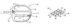
- FIG. 1is a top plan view of an interbody spinal implant having a surface configuration in accordance with the present invention.
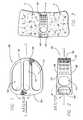
- FIG. 1Ais a perspective view of an implant having arcuate surfaces and an end cap in accordance with an embodiment of the present invention.
- FIG. 1Bis a top elevational view of an implant having a leading end, a trailing end, and sides forming a circle in accordance with an embodiment of the present invention.
- FIG. 1Cis a graphical representation of a motion preserving device in accordance with an embodiment of the present invention.
- FIG. 2is a side elevation view of the spinal implant of FIG. 1 .
- FIG. 3is a side elevation view of the interbody spinal implant of FIG. 1 installed in an implantation site formed across the disc space between two adjacent vertebral bodies of the spine shown in partial cross-section.
- FIG. 4is an enlarged fragmentary top plan view of an implant surface of one embodiment of the present invention from a view taken along area 4 of FIG. 1 .
- FIG. 5is a fragmentary side elevation view of the implant surface of FIG. 4 from a view taken along area 5 of FIG. 2 .
- FIG. 6is a fragmentary end elevation view of FIG. 4 .
- FIG. 7is a fragmentary perspective view of the implant surface of FIG. 4 .
- FIG. 8is an enlarged fragmentary top plan view of a second embodiment of the implant surface of the present invention from a view taken along area 8 of FIG. 1 .
- FIG. 9is a fragmentary side elevation view of the implant surface of FIG. 8 from a view taken along area 9 of FIG. 2 .
- FIG. 10is a fragmentary end view of the implant surface of FIG. 8 .
- FIG. 11is a fragmentary perspective view of the implant surface of FIG. 8 .
- FIG. 12Ais an enlarged fragmentary top plan view of a third embodiment of the implant surface of the present invention from a view taken along area 12 of FIG. 1 .
- FIG. 12Bis an enlarged fragmentary top plan view of another embodiment of the implant surface of the present invention from a view taken along area 12 of FIG. 1 .
- FIG. 13is a fragmentary side elevation view of the implant surface of FIG. 12A from a view taken along area 13 of FIG. 2 .
- FIG. 14is a fragmentary end view of FIG. 12A .
- FIG. 14Ais an enlarged fragmentary side view of a groove having a U-shape in accordance with an embodiment of the present invention from a view taken along area 14 A of FIG. 14 .
- FIG. 14Bis an enlarged fragmentary side view of a groove having a box-shape in accordance with an embodiment of the present invention from a view taken along area 14 B of FIG. 14 .
- FIG. 14Cis a fragmentary end view of a plurality of surface projections spaced apart from one another in accordance with an embodiment of the present invention.
- FIG. 15is a fragmentary perspective view of the implant surface of FIG. 12A .
- FIG. 16is an enlarged fragmentary top plan view of a fourth embodiment of the implant surface of the present invention from a view taken along area 16 of FIG. 1 .
- FIG. 17is a fragmentary side elevation view of the implant surface of FIG. 16 from a view taken along area 17 of FIG. 2 .
- FIG. 18is a fragmentary end view of FIG. 16 .
- FIG. 19Ais an enlarged fragmentary perspective view of the implant surface of FIG. 16 .
- FIG. 19Bis an enlarged fragmentary perspective view of a variation on the second and third surface projections of the fourth embodiment of the implant surface of the present invention with a cleave therethrough.
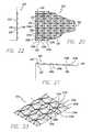
- FIG. 20is an enlarged fragmentary top plan view of a fifth embodiment of the implant surface of the present invention from a view taken along area 20 of FIG. 1 .
- FIG. 21is a fragmentary side elevation view of the implant surface of FIG. 20 from a view taken along line 21 of FIG. 2 .
- FIG. 22is a fragmentary end view of FIG. 20 .
- FIG. 23is an enlarged fragmentary perspective view of the implant surface of FIG. 20 .
- FIGS. 24A and 24Bare perspective and side elevation views, respectively, of a prior art implant surface having forward facing ratchetings.
- an interbody spinal implant 100has a leading end 102 , a trailing end 104 , an upper surface 106 , a lower surface 108 , and a side wall 110 between upper and lower surfaces 106 , 108 .
- Upper and lower surfaces 106 , 108may converge from trailing end 104 to leading end 102 along a longitudinal axis L of implant 100 as shown, or may diverge, be parallel, or any combination thereof.
- Upper and lower surfaces 106 , 108are configured to be placed against and in contact or engagement with the bone of vertebral bodies V of two adjacent vertebrae adjacent disc D of the human spine.
- Upper and lower surfaces 106 , 108 and side wall 110may include large and/or small openings 112 , 114 , and 116 , respectively, to permit bone growth into and through implant 100 .
- Upper and lower surfaces 106 , 108 of implant 100can be generally planar as shown in the figures, or can be opposed arcuate surfaces as shown and described in U.S. Pat. No. 5,593,409, incorporated herein by reference, or any other configuration suitable for the desired use.
- surface configuration 120includes surface projections 122 configured to facilitate insertion of implant 100 into an implantation site while resisting expulsion of implant 100 in a direction opposite to the direction of insertion.
- Each of surface projections 122has an angled forward facet 124 directed at least in part toward leading end 102 of implant 100 and a rearward facet 126 directed at least in part toward trailing end 104 of implant 100 .
- Forward facet 124has a length greater than the length of rearward facet 126 .
- Rearward facet 126has a slope that is steeper than the slope of forward facet 124 .
- the base of rearward facet 126forms an angle of approximately 90 degrees with respect to upper and/or lower surfaces 106 , 108 of implant 100 . It is appreciated that the angle of the base of rearward facet 126 with respect to upper and/or lower surfaces 106 , 108 of implant 100 may be perpendicular to, greater than perpendicular to, or less than perpendicular to the base of the surface where the facet arises.
- Forward facet 124forms an angle in the range of approximately 10 to 60 degrees, with 25-45 degrees being preferred, with respect to upper and/or lower surfaces 106 , 108 .
- Each one of surface projections 122also has a left side facet 132 and a right side facet 134 directed toward the sides of implant 100 .
- a plurality of surface projections 122are spaced apart laterally (side to side) by longitudinal grooves 130 formed along the longitudinal axis L of implant 100 .
- longitudinal grooves 130have a V-shaped horizontal cross-section.
- the lower most portions of left and right side facets 132 , 134 of consecutive side-by-side projections 122can be coincident with each other or may be spaced apart, any space therebetween can be at least in part flat, curved, sloped or otherwise configured.
- Each surface projection 122has left and right side facets 132 , 134 that converge to form a high point or peak 136 at the top of each surface projection 122 .
- Each peak 136can be aligned along lines that are perpendicular, parallel, and/or diagonally oriented to longitudinal axis L of implant 100 .
- the left and right side facets 132 , 134resist side-to-side motion of implant 100 after it is inserted into the implantation space.
- Peaks 136engage the bone of vertebral bodies V adjacent to implant 100 in the implantation site. It is appreciated that in a variation of the present invention, the peaks may be modified such as to be truncated or cut off to have a broader rather than sharper upper most surface. Moreover, the peaks can be cleaved in one or more directions so as to increase the surface area useful for engaging the bone of the vertebral bodies.
- the relieved areas of the cleaved projectionsare useful for containing and carrying fusion promoting substances other than bone such as bone morphogenetic proteins and genetic materials coding for the production of bone, or bone itself which could by way of example be in the form of a paste.
- longitudinal grooves 130can have horizontal cross-sections in a variety of configurations such as, without limitation, square-shaped or U-shaped configurations.
- Sequential projectionscan be positioned on an implant wherein each surface projection has forward facing facets facing the same direction such that consecutive projections are oriented forward facing facet to rearward facing facet.
- the lower most portion of the slope of the forward facing facet of a first surface projection in a sequencecan be coincident with the rearward facet of the next surface projection in the sequence.
- the forward facet of a first surface projection and the rearward facet of the next surface projection in a sequencecan be spaced apart and the space can be at least in part flat, curved, or any other surface configuration suitable for the intended use.
- the surface projectionscan be oriented relative to one another to form an array and are preferably geometrically disposed relative to one another in a pattern wherein at least a portion of the projection is aligned along a longitudinal, horizontal, diagonal, or curved line.
- the surface of the present inventioncan be useful with spinal implants of various configurations, including configurations wherein at least one of leading end, trailing end, and sides of the spinal implant is curved.
- the leading end, trailing end, and sides of the spinal implantcan form an oval, an oblong, or a circle.
- a second embodiment of the surface configuration of the present inventionis generally referred to by the numeral 220 .
- Surface configuration 220includes surface projections 222 to facilitate insertion of implant 100 into an implantation site while resisting expulsion of implant 100 in a direction opposite to the direction of insertion.
- Each of surface projections 222has an angled forward facet 224 directed at least in part toward leading end 202 of implant 100 and a rearward facet 226 directed at least in part toward trailing end 204 of implant 100 .
- Forward facet 224has a length greater than the length of rearward facet 226 .
- Rearward facet 226has a slope that is steeper than the slope of forward facet 224 . In this embodiment, the base of rearward facet 226 forms an angle of approximately 45 degrees with respect to upper and/or lower surfaces 206 , 208 of implant 100 .
- Each one of surface projections 222has a left side facet 232 and a right side facet 234 directed toward the sides of implant 100 , and forward facet 224 and rearward facet 226 .
- longitudinal grooves 230have a V-shaped horizontal cross-section.
- the lower most portions of left and right side facets 232 , 234 of consecutive side-by-side projections 222can be coincident with each other or may be spaced apart, any space therebetween can be at least in part flat, curved, sloped or otherwise configured.
- Each surface projectionhas left and right side facets 232 , 234 that converge to form a high point or peak 236 at the top of each surface projections 222 .
- Each peak 236can be aligned along lines that are perpendicular, parallel, and/or diagonally oriented to the longitudinal axis L of implant 100 .
- the left and right side facets 232 , 234resist side-to-side motion of implant 100 after it is inserted into the implantation space. Peaks 236 engage the bone of the vertebral bodies adjacent to implant 100 in the implantation site.
- Surface configuration 320includes surface projections 322 to facilitate insertion of implant 100 into an implantation site while resisting expulsion of implant 100 in a direction opposite to the direction of insertion.
- Each of surface projections 322has an angled forward facet 324 directed at least in part toward leading end 302 of implant 100 and a rearward facet 326 directed at least In part toward trailing end 304 of implant 100 .
- Forward facet 324has a length greater than the length of rearward facet 326 .
- Rearward facet 326has a slope that is steeper than the slope of forward facet 324 .
- the base of rearward facet 326is “back cut” to form an angle greater than 90 degrees with respect to upper and/or lower surfaces 306 , 308 of implant 100 .
- the rearward facet 326 and the forward facet 324have a negative direction of inclination, i.e., a negative slope, as shown in FIG. 13 .
- the configuration of rearward facet 326further enhances resistance of motion of the implant in a direction opposite to the direction of insertion.
- the angle of the base of rearward facet 326 with respect to upper and/or lower surfaces 306 , 308 of implant 100can be any other angle suitable for the intended purpose of the present invention.
- Each one of surface projections 322has a left side facet 332 and a right side facet 334 directed toward the sides of implant 100 , and a forward facet 324 and a rearward facet 326 .
- longitudinal grooves 330have a V-shaped horizontal cross section.
- the lower most portions of left and right side facets 332 , 334 of consecutive side-by-side projections 322can be coincident with each other or may be spaced apart, and any space therebetween can be at least in part flat, curved, sloped or otherwise configured.
- Each surface projection 322has left and right side facets 332 , 334 that converge to form a high point or peak 336 at the top of each surface projection 322 .
- Each peak 336can be aligned along lines that are perpendicular, parallel, and/or diagonally oriented to the longitudinal axis L of implant 100 .
- the left and right side facets 332 , 334resist side-to-side motion of implant 100 after it is inserted into the implantation space. Peaks 336 engage the bone of vertebral bodies V adjacent to implant 100 in the implantation site.
- a fourth embodiment of the surface configuration of the present inventionis generally referred to by the numeral 420 .
- Surface configuration 420includes surface projections 422 configured to facilitate insertion of implant 100 in the direction of insertion into an implantation site while resisting expulsion of implant 100 in a direction opposite to the direction of insertion.
- Each of surface projections 422has an angled forward facet 424 directed toward leading end 402 of implant 100 and a rearward portion 426 directed toward trailing end 404 of implant 100 .
- Forward facet 424has a length greater than the length of rearward portion 426 .
- Rearward portion 426has a slope that is steeper than the slope of forward facet 424 .
- the base of rearward portion 426forms an angle of approximately 90 degrees with respect to upper and/or lower surfaces 406 , 408 of implant 100 .
- Rearward portion 426can be a portion of surface projection 422 , such as a facet, an edge, or a line for example.
- Each one of surface projections 422has a left side forward facet 450 , a right side forward facet 452 , a left side rearward facet 454 , and a right side rearward facet 456 directed toward the front and sides, and directed toward the rear and sides of implant 100 , respectively, and forward facet 424 and rearward portion 426 .
- Surface configuration 420can further include a second plurality of surface projections 460 having at least a left forward side facet 462 and a right forward side facet 464 directed at least in part toward leading end 402 and sides of implant 100 , respectively, and at least one rearward facet 466 directed at least in part toward trailing end 400 .
- Left and right forward side facets 462 , 464have at least a first portion in a plane at an angle to the longitudinal axis of implant 100 .
- Second surface projections 460can be interspersed with surface projections 422 .
- Surface configuration 420can further comprise a third plurality of surface projections 470 having at least a left rearward side facet 472 and a right rearward side facet 474 directed at least in part toward trailing end 404 and sides of implant 100 , respectively, and at least one forward facet 476 directed at least in part toward leading end 402 .
- Left and right rearward side facets 472 , 474have at least a first portion in a plane at an angle to the longitudinal axis of implant 100 .
- Third surface projections 470can be interspersed with surface projections 422 and/or second surface projections 460 .
- Surface projections 422may have a length approximating the combined length of second surface projections 460 and third surface projections 470 .
- surface configuration 420has angled grooves 440 a - k that form a plurality of surface projections 422 .
- angled grooves 440 a - kare formed at an angle that is approximately 45 degrees to longitudinal axis L of spinal implant 100 and in this example, angled grooves 440 a - k are approximately 90 degrees to one another.
- the angled grooves 440 a - kcan be formed, if machined, by first passing a cutting element at a 45 degree angle to the longitudinal axis L of implant 100 and then passing the cutting element at a 90 degree angle to the path of the first pass of the cutting element, or otherwise formed by casting, molding, and other methods for forming a surface configuration.
- angled grooves 400 a - kcan be formed at various angles to the longitudinal axis L of implant 100 and to each other. For example, such angles can be less than 180 degrees.
- angled grooves 440 a - khave a V-shaped horizontal cross-section.
- Each surface projection 422has left and right side facets 432 and 434 that are convergent and form a high point or peak 436 at the top of each surface projections 422 .
- Each peak 436can be aligned along lines that are horizontally, longitudinally, and/or diagonally oriented along implant 100 .
- the left and right side forward and rearward facets 450 , 452 , 454 , 456function to prevent side-to-side motion of implant 100 after it is inserted into the implantation space. Peaks 436 may also function like teeth to engage the bone of vertebral bodies V adjacent to the implant in the implantation site.
- FIG. 19Bshows a variation of second and third surface projections 460 ′, 470 ′ that can be cleaved in one or more directions to increase the number of exposed sides of each projection and thus increase the surface area of the implant bone engaging surface available to contact the bone of the vertebral bodies.
- a preferred embodiment of this variation of the second and third surface projections 460 ′, 470 ′are cleaved by a longitudinal groove.
- a fifth embodiment of the surface configuration of the present inventionis generally referred to by the numeral 520 .
- Surface configuration 520includes surface projections 522 to facilitate insertion of implant 100 into an implantation site while resisting expulsion of implant 100 in a direction opposite to the direction of insertion.
- Surface projections 522can be cleaved in one or more directions to increase the number of exposed sides of each projection and thus increase the surface area of the implant bone engaging surface available to contact the bone of the vertebral bodies.
- the surface projectionscan be cleaved by a longitudinal cut 540 generally parallel to the longitudinal axis L of implant 100 to form a surface projection having nine exposed sides.
- the surface projectionsmay further be cleaved by a horizontal cut 542 generally perpendicular to the longitudinal axis L of implant 100 to form a surface projection having eighteen exposed sides.
- the cutscan penetrate the surface projection at a depth substantially equal to that of the height of the surface projections as measured from the upper or lower surfaces of the implant.
- the cutscan be oriented along at least one of the longitudinal axis of the implant, an axis perpendicular to the longitudinal axis of said implant, and an axis at an angle between the longitudinal axis and the axis perpendicular to the longitudinal axis of the implant. It is appreciated that cuts 540 and 542 may be formed as part of the molding process for forming the surface projections.
- each of surface projections 522has angled forward facet 524 a , 524 b directed at least in part toward leading end 502 of implant 100 and rearward facets 526 a , 526 b directed at least in part toward trailing end 504 of implant 100 .
- Forward facet 524has a length greater than the length of rearward facet 526 .
- Rearward facets 526 a , 526 bhave a slope that is steeper than the slope of forward facets 524 a , 524 b .
- the cleaved portion of surface projection 522can be spaced apart by a predetermined distance and the space can be at least in part flat, curved, or any other surface configuration suitable for the intended use.
- the base of rearward facets 526 a , 526 bforms an angle of approximately 45 degrees with respect to upper and/or lower surfaces 506 , 508 of implant 100 .
- Each one of surface projections 522has left side facets 532 a , 532 b and right side facets 534 a , 534 b directed toward the sides of implant 100 , and forward facets 524 a , 524 b and rearward facet 526 a , 526 b .
- longitudinal grooves 530have a V-shaped horizontal cross-section and each surface projection 522 has left and right side facets 532 a , 532 b , 534 a , 534 b that converge toward one another.
- the left and right side facets 532 a , 532 b , 534 a , 534 bresist side-to-side motion of implant 100 after it is inserted into the implantation space.
- the surface configuration of the present inventioncan be formed by molding, machining or otherwise.
- a preferred surface configuration of the present inventionmay readily be machined by milling from side to side, across the upper and lower vertebral body engaging surfaces, surface projections.
- a milling machine with a cutting tool having an angled cutting face such as a V-shaped profilecan then be run through the plurality of surface projections parallel to the longitudinal axis of the implant to form the above-described surface.
- the V-shaped cutting tool of the milling machinehas faces with an angle of approximately 90 degrees, which faces are at a 45-degree angle to the plane of the surfaces being so machined.
- the angle of the cutting facescan be more or less than 90 degrees
- the angle of the cutting face to the surface to be cutcan be more or less than 45 degrees
- the cutting elementmay be run at an angle.
- this anglemay be at 45 degrees to the longitudinal axis of the implant and each surface projection can be formed by two grooves crossing the projections at a 90 degree angle to each other.
- the spinal implants of the present inventionare made of artificial or naturally occurring materials suitable for implantation in the human spine.
- the implantscan comprise bone including, but not limited to, cortical bone, materials other than bone, such as metals including, but not limited to, titanium and its alloys or ASTM material, surgical grade plastics, plastic composites, ceramics, or other materials suitable for use as a spinal implant.
- the implants of the present inventioncan further comprise or be combined with bone growth promoting materials, including but not limited to, bone, bone morphogenetic proteins, hydroxyapatite, and genes coding for the production of bone.
- the implantscan be treated with a bone growth promoting substance, can be a source of osteogenesis, or can be bioabsorbable at least in part.
- the implants of the present inventioncan be formed of a porous material.
- the spinal implants of the present inventioncan be for the purpose of achieving fusion.
- the upper and lower surfaces of the fusion implantscan include at least one opening, each in communication with the other, to permit for the growth of bone from vertebral body to adjacent vertebral body through the implant.
- the implantcan have an internal chamber and may also have an access opening for accessing the internal chamber, in which case the implant can further have a cover such as a cap 101 ′ (shown in FIG. 1A ) to close the access opening at least in part. Openings in the upper and lower surfaces of the implant can communicate with the internal chamber to permit further growth of bone from vertebral body to adjacent vertebral body through the implant.
- the internal chambercan contain bone growth promoting materials, including but not limited to, bone, bone morphogenetic proteins, hydroxyapatite, and genes coding for the production of bone.
- the implants of the present inventioncan be formed of a material that intrinsically participates in the growth of bone from one of the adjacent vertebral bodies to the other of the adjacent vertebral bodies.
- the configuration of the surfaceis based on a plurality of surface projections disposed in arrays, each surface projection comprising at least one leading facet and at least one opposing trailing facet, in which the leading facet has a length greater than the trailing facet and the trailing facet has a steeper slope than the slope of the leading facet.
- the surface configurationis located on at least a portion of one of the opposed vertebral body engaging surfaces of the spinal implant.
- FIGS. 1 , 2 , and 3is an interbody spinal fusion implant
- the surface configuration of the present inventionis applicable to any interbody spinal fusion implants, including but not limited to, an artificial disc or motion preserving device having opposed surfaces incorporating the present inventive teachings for engaging each of the adjacent vertebral bodies.
Landscapes
- Health & Medical Sciences (AREA)
- Engineering & Computer Science (AREA)
- Biomedical Technology (AREA)
- Orthopedic Medicine & Surgery (AREA)
- Heart & Thoracic Surgery (AREA)
- Cardiology (AREA)
- Oral & Maxillofacial Surgery (AREA)
- Transplantation (AREA)
- Neurology (AREA)
- Vascular Medicine (AREA)
- Life Sciences & Earth Sciences (AREA)
- Animal Behavior & Ethology (AREA)
- General Health & Medical Sciences (AREA)
- Public Health (AREA)
- Veterinary Medicine (AREA)
- Prostheses (AREA)
Abstract
Description
Claims (110)
Priority Applications (1)
| Application Number | Priority Date | Filing Date | Title |
|---|---|---|---|
| US10/683,071US7972381B2 (en) | 1999-12-08 | 2003-10-10 | Spinal implant surface configuration with a projection having a back cut |
Applications Claiming Priority (2)
| Application Number | Priority Date | Filing Date | Title |
|---|---|---|---|
| US09/457,228US6827740B1 (en) | 1999-12-08 | 1999-12-08 | Spinal implant surface configuration |
| US10/683,071US7972381B2 (en) | 1999-12-08 | 2003-10-10 | Spinal implant surface configuration with a projection having a back cut |
Related Parent Applications (1)
| Application Number | Title | Priority Date | Filing Date |
|---|---|---|---|
| US09/457,228ContinuationUS6827740B1 (en) | 1999-12-08 | 1999-12-08 | Spinal implant surface configuration |
Publications (2)
| Publication Number | Publication Date |
|---|---|
| US20040117018A1 US20040117018A1 (en) | 2004-06-17 |
| US7972381B2true US7972381B2 (en) | 2011-07-05 |
Family
ID=23815919
Family Applications (4)
| Application Number | Title | Priority Date | Filing Date |
|---|---|---|---|
| US09/457,228Expired - LifetimeUS6827740B1 (en) | 1999-12-08 | 1999-12-08 | Spinal implant surface configuration |
| US09/921,844AbandonedUS20010047208A1 (en) | 1999-12-08 | 2001-08-03 | Spinal implant surface configuration |
| US09/921,851Expired - LifetimeUS7166129B2 (en) | 1999-12-08 | 2001-08-03 | Method for forming a spinal implant surface configuration |
| US10/683,071Expired - Fee RelatedUS7972381B2 (en) | 1999-12-08 | 2003-10-10 | Spinal implant surface configuration with a projection having a back cut |
Family Applications Before (3)
| Application Number | Title | Priority Date | Filing Date |
|---|---|---|---|
| US09/457,228Expired - LifetimeUS6827740B1 (en) | 1999-12-08 | 1999-12-08 | Spinal implant surface configuration |
| US09/921,844AbandonedUS20010047208A1 (en) | 1999-12-08 | 2001-08-03 | Spinal implant surface configuration |
| US09/921,851Expired - LifetimeUS7166129B2 (en) | 1999-12-08 | 2001-08-03 | Method for forming a spinal implant surface configuration |
Country Status (1)
| Country | Link |
|---|---|
| US (4) | US6827740B1 (en) |
Cited By (21)
| Publication number | Priority date | Publication date | Assignee | Title |
|---|---|---|---|---|
| US20100057206A1 (en)* | 2008-09-02 | 2010-03-04 | Duffield William E | Intervertebral fusion implant |
| US20100312345A1 (en)* | 2009-06-04 | 2010-12-09 | Duffield William E | Intervertebral fusion implant |
| US8313528B1 (en) | 2008-03-27 | 2012-11-20 | Spinelogik, Inc. | Intervertebral fusion device and method of use |
| US8333804B1 (en) | 2008-03-27 | 2012-12-18 | Spinelogik, Inc. | Intervertebral fusion device and method of use |
| US9149365B2 (en) | 2013-03-05 | 2015-10-06 | Globus Medical, Inc. | Low profile plate |
| US9237957B2 (en) | 2011-09-16 | 2016-01-19 | Globus Medical, Inc. | Low profile plate |
| US9326861B2 (en) | 2012-08-03 | 2016-05-03 | Globus Medical, Inc. | Stabilizing joints |
| US9427324B1 (en) | 2010-02-22 | 2016-08-30 | Spinelogik, Inc. | Intervertebral fusion device and method of use |
| US9486327B2 (en) | 2014-05-15 | 2016-11-08 | Globus Medical, Inc. | Standalone interbody implants |
| US9539109B2 (en) | 2011-09-16 | 2017-01-10 | Globus Medical, Inc. | Low profile plate |
| US9545320B2 (en) | 2014-05-15 | 2017-01-17 | Globus Medical, Inc. | Standalone interbody implants |
| US9681959B2 (en) | 2011-09-16 | 2017-06-20 | Globus Medical, Inc. | Low profile plate |
| US9848994B2 (en) | 2011-09-16 | 2017-12-26 | Globus Medical, Inc. | Low profile plate |
| US9895237B2 (en) | 2010-04-08 | 2018-02-20 | Globus Medical, Inc. | Intervertebral implant |
| US9968461B2 (en) | 2014-05-15 | 2018-05-15 | Globus Medical, Inc. | Standalone interbody implants |
| US10245155B2 (en) | 2011-09-16 | 2019-04-02 | Globus Medical, Inc. | Low profile plate |
| US10271960B2 (en) | 2017-04-05 | 2019-04-30 | Globus Medical, Inc. | Decoupled spacer and plate and method of installing the same |
| US10376385B2 (en) | 2017-04-05 | 2019-08-13 | Globus Medical, Inc. | Decoupled spacer and plate and method of installing the same |
| US10925749B2 (en) | 2013-03-15 | 2021-02-23 | Revivo Medical, Llc | Intervertebral cage and method of treating vertebrae with an intervertebral cage |
| US11160666B2 (en) | 2014-05-15 | 2021-11-02 | Globus Medical, Inc. | Laterally insertable intervertebral spinal implant |
| US11717417B2 (en) | 2011-09-16 | 2023-08-08 | Globus Medical Inc. | Low profile plate |
Families Citing this family (245)
| Publication number | Priority date | Publication date | Assignee | Title |
|---|---|---|---|---|
| EP0873145A2 (en) | 1996-11-15 | 1998-10-28 | Advanced Bio Surfaces, Inc. | Biomaterial system for in situ tissue repair |
| EP1198208B1 (en) | 1999-05-05 | 2013-07-10 | Warsaw Orthopedic, Inc. | Nested interbody spinal fusion implants |
| US6592624B1 (en) | 1999-11-24 | 2003-07-15 | Depuy Acromed, Inc. | Prosthetic implant element |
| US7115143B1 (en) | 1999-12-08 | 2006-10-03 | Sdgi Holdings, Inc. | Orthopedic implant surface configuration |
| US6827740B1 (en)* | 1999-12-08 | 2004-12-07 | Gary K. Michelson | Spinal implant surface configuration |
| US6350283B1 (en) | 2000-04-19 | 2002-02-26 | Gary K. Michelson | Bone hemi-lumbar interbody spinal implant having an asymmetrical leading end and method of installation thereof |
| US7462195B1 (en) | 2000-04-19 | 2008-12-09 | Warsaw Orthopedic, Inc. | Artificial lumbar interbody spinal implant having an asymmetrical leading end |
| AU2001274821A1 (en)* | 2000-06-13 | 2001-12-24 | Gary K. Michelson | Manufactured major long bone ring implant shaped to conform to a prepared intervertebral implantation space |
| US20020111680A1 (en)* | 2000-06-13 | 2002-08-15 | Michelson Gary K. | Ratcheted bone dowel |
| US7833250B2 (en) | 2004-11-10 | 2010-11-16 | Jackson Roger P | Polyaxial bone screw with helically wound capture connection |
| US8377100B2 (en) | 2000-12-08 | 2013-02-19 | Roger P. Jackson | Closure for open-headed medical implant |
| US6520993B2 (en) | 2000-12-29 | 2003-02-18 | Depuy Acromed, Inc. | Spinal implant |
| US6890355B2 (en) | 2001-04-02 | 2005-05-10 | Gary K. Michelson | Artificial contoured spinal fusion implants made of a material other than bone |
| US6989031B2 (en) | 2001-04-02 | 2006-01-24 | Sdgi Holdings, Inc. | Hemi-interbody spinal implant manufactured from a major long bone ring or a bone composite |
| US20050177238A1 (en)* | 2001-05-01 | 2005-08-11 | Khandkar Ashok C. | Radiolucent bone graft |
| EP2055267B1 (en)* | 2001-05-01 | 2013-04-17 | Amedica Corporation | Radiolucent bone graft |
| US7776085B2 (en) | 2001-05-01 | 2010-08-17 | Amedica Corporation | Knee prosthesis with ceramic tibial component |
| US7695521B2 (en) | 2001-05-01 | 2010-04-13 | Amedica Corporation | Hip prosthesis with monoblock ceramic acetabular cup |
| US6974480B2 (en) | 2001-05-03 | 2005-12-13 | Synthes (Usa) | Intervertebral implant for transforaminal posterior lumbar interbody fusion procedure |
| US6719794B2 (en)* | 2001-05-03 | 2004-04-13 | Synthes (U.S.A.) | Intervertebral implant for transforaminal posterior lumbar interbody fusion procedure |
| EP1408874B1 (en) | 2001-06-14 | 2012-08-08 | Amedica Corporation | Metal-ceramic composite articulation |
| US6558424B2 (en) | 2001-06-28 | 2003-05-06 | Depuy Acromed | Modular anatomic fusion device |
| US6726720B2 (en) | 2002-03-27 | 2004-04-27 | Depuy Spine, Inc. | Modular disc prosthesis |
| DE20205016U1 (en)* | 2002-03-30 | 2003-08-14 | Mathys Medizinaltechnik Ag, Bettlach | Surgical implant |
| US11224464B2 (en) | 2002-05-09 | 2022-01-18 | Roger P. Jackson | Threaded closure with inwardly-facing tool engaging concave radiused structures and axial through-aperture |
| US7001433B2 (en) | 2002-05-23 | 2006-02-21 | Pioneer Laboratories, Inc. | Artificial intervertebral disc device |
| US8388684B2 (en) | 2002-05-23 | 2013-03-05 | Pioneer Signal Technology, Inc. | Artificial disc device |
| AU2003226586A1 (en) | 2002-09-19 | 2004-04-08 | Malan De Villiers | Intervertebral prosthesis |
| AU2003297195A1 (en) | 2002-12-17 | 2004-07-22 | Amedica Corporation | Total disc implant |
| US7192447B2 (en) | 2002-12-19 | 2007-03-20 | Synthes (Usa) | Intervertebral implant |
| ZA200506029B (en) | 2003-01-31 | 2006-10-25 | Spinalmotion Inc | Spinal Midline Indicator |
| WO2004066884A1 (en) | 2003-01-31 | 2004-08-12 | Spinalmotion, Inc. | Intervertebral prosthesis placement instrument |
| WO2004084742A1 (en)* | 2003-03-24 | 2004-10-07 | Theken Surgical Llc | Spinal implant adjustment device |
| US7105024B2 (en) | 2003-05-06 | 2006-09-12 | Aesculap Ii, Inc. | Artificial intervertebral disc |
| US7291173B2 (en) | 2003-05-06 | 2007-11-06 | Aesculap Ii, Inc. | Artificial intervertebral disc |
| DE10324108B3 (en)* | 2003-05-21 | 2005-01-27 | Aesculap Ag & Co. Kg | Backbone implant is inserted with contracted contact disc which is expanded to optimum area following insertion |
| US7575599B2 (en) | 2004-07-30 | 2009-08-18 | Spinalmotion, Inc. | Intervertebral prosthetic disc with metallic core |
| US10052211B2 (en) | 2003-05-27 | 2018-08-21 | Simplify Medical Pty Ltd. | Prosthetic disc for intervertebral insertion |
| US7442211B2 (en) | 2003-05-27 | 2008-10-28 | Spinalmotion, Inc. | Intervertebral prosthetic disc |
| DE10330698B4 (en) | 2003-07-08 | 2005-05-25 | Aesculap Ag & Co. Kg | Intervertebral implant |
| DE20310433U1 (en) | 2003-07-08 | 2003-09-04 | Aesculap AG & Co. KG, 78532 Tuttlingen | Surgical device for inserting dual component implant into appropriate space at spine, comprising particularly shaped holding area |
| US7153325B2 (en)* | 2003-08-01 | 2006-12-26 | Ultra-Kinetics, Inc. | Prosthetic intervertebral disc and methods for using the same |
| DE10339170B4 (en) | 2003-08-22 | 2009-10-15 | Aesculap Ag | Intervertebral implant |
| US7041137B2 (en)* | 2003-10-07 | 2006-05-09 | Lanx, Llc | Spinal implant |
| US8974528B2 (en)* | 2003-10-08 | 2015-03-10 | The University Of North Carolina At Chapel Hill | Spine replacement system for the treatment of spine instability and degenerative disc disease |
| EP2113227B1 (en)* | 2004-02-04 | 2015-07-29 | LDR Medical | Intervertebral disc prosthesis |
| US7247169B1 (en)* | 2004-02-23 | 2007-07-24 | Aesculap Implant Systems, Inc. | Kit of spine gauge blocks and a tool assembly |
| US7544208B1 (en) | 2004-05-03 | 2009-06-09 | Theken Spine, Llc | Adjustable corpectomy apparatus |
| DE202004009542U1 (en) | 2004-06-16 | 2004-08-12 | Aesculap Ag & Co. Kg | Artificial intervertebral disk, comprising core with intensely curved upper and less curved lower surface |
| US7585326B2 (en) | 2004-08-06 | 2009-09-08 | Spinalmotion, Inc. | Methods and apparatus for intervertebral disc prosthesis insertion |
| US20070156241A1 (en) | 2004-08-09 | 2007-07-05 | Reiley Mark A | Systems and methods for the fixation or fusion of bone |
| US8388667B2 (en) | 2004-08-09 | 2013-03-05 | Si-Bone, Inc. | Systems and methods for the fixation or fusion of bone using compressive implants |
| US20180228621A1 (en) | 2004-08-09 | 2018-08-16 | Mark A. Reiley | Apparatus, systems, and methods for the fixation or fusion of bone |
| US9949843B2 (en) | 2004-08-09 | 2018-04-24 | Si-Bone Inc. | Apparatus, systems, and methods for the fixation or fusion of bone |
| US9662158B2 (en) | 2004-08-09 | 2017-05-30 | Si-Bone Inc. | Systems and methods for the fixation or fusion of bone at or near a sacroiliac joint |
| US20060036251A1 (en) | 2004-08-09 | 2006-02-16 | Reiley Mark A | Systems and methods for the fixation or fusion of bone |
| US8414648B2 (en) | 2004-08-09 | 2013-04-09 | Si-Bone Inc. | Apparatus, systems, and methods for achieving trans-iliac lumbar fusion |
| US8425570B2 (en) | 2004-08-09 | 2013-04-23 | Si-Bone Inc. | Apparatus, systems, and methods for achieving anterior lumbar interbody fusion |
| US7794500B2 (en)* | 2004-10-27 | 2010-09-14 | Felix Brent A | Surgical implant |
| USD524942S1 (en) | 2005-05-23 | 2006-07-11 | Felix Brent A | Surgical implant |
| US7875080B2 (en)* | 2004-11-10 | 2011-01-25 | Warsaw Orthopedic, Inc. | Intervertebral spacer |
| US20060111780A1 (en) | 2004-11-22 | 2006-05-25 | Orthopedic Development Corporation | Minimally invasive facet joint hemi-arthroplasty |
| US8021392B2 (en) | 2004-11-22 | 2011-09-20 | Minsurg International, Inc. | Methods and surgical kits for minimally-invasive facet joint fusion |
| US20060111779A1 (en) | 2004-11-22 | 2006-05-25 | Orthopedic Development Corporation, A Florida Corporation | Minimally invasive facet joint fusion |
| US7736380B2 (en) | 2004-12-21 | 2010-06-15 | Rhausler, Inc. | Cervical plate system |
| US8083797B2 (en) | 2005-02-04 | 2011-12-27 | Spinalmotion, Inc. | Intervertebral prosthetic disc with shock absorption |
| US20060235520A1 (en)* | 2005-04-19 | 2006-10-19 | Pannu Yashdip S | Spinal implant apparatus, method and system |
| US20060241758A1 (en)* | 2005-04-20 | 2006-10-26 | Sdgi Holdings, Inc. | Facet spacers |
| US11096796B2 (en) | 2005-05-06 | 2021-08-24 | Titan Spine, Llc | Interbody spinal implant having a roughened surface topography on one or more internal surfaces |
| US8992622B2 (en) | 2005-05-06 | 2015-03-31 | Titan Spine, Llc | Interbody spinal implant having a roughened surface topography |
| US8758442B2 (en) | 2005-05-06 | 2014-06-24 | Titan Spine, Llc | Composite implants having integration surfaces composed of a regular repeating pattern |
| US8585767B2 (en) | 2005-05-06 | 2013-11-19 | Titan Spine, Llc | Endplate-preserving spinal implant with an integration plate having durable connectors |
| US8403991B2 (en) | 2005-05-06 | 2013-03-26 | Titan Spine Llc | Implant with critical ratio of load bearing surface area to central opening area |
| US7662186B2 (en)* | 2005-05-06 | 2010-02-16 | Titan Spine, Llc | Anterior interbody spinal implant |
| US8758443B2 (en) | 2005-05-06 | 2014-06-24 | Titan Spine, Llc | Implants with integration surfaces having regular repeating surface patterns |
| US8562684B2 (en) | 2005-05-06 | 2013-10-22 | Titan Spine, Llc | Endplate-preserving spinal implant with an integration plate having a roughened surface topography |
| US20120312779A1 (en) | 2005-05-06 | 2012-12-13 | Titian Spine, LLC | Methods for manufacturing implants having integration surfaces |
| US8480749B2 (en) | 2005-05-06 | 2013-07-09 | Titan Spine, Llc | Friction fit and vertebral endplate-preserving spinal implant |
| US8617248B2 (en) | 2005-05-06 | 2013-12-31 | Titan Spine, Llc | Spinal implant having variable ratios of the integration surface area to the axial passage area |
| US8562685B2 (en) | 2005-05-06 | 2013-10-22 | Titan Spine, Llc | Spinal implant and integration plate for optimizing vertebral endplate contact load-bearing edges |
| US8814939B2 (en) | 2005-05-06 | 2014-08-26 | Titan Spine, Llc | Implants having three distinct surfaces |
| US8585766B2 (en) | 2005-05-06 | 2013-11-19 | Titan Spine, Llc | Endplate-preserving spinal implant with an integration plate having durable connectors |
| US8545568B2 (en) | 2005-05-06 | 2013-10-01 | Titan Spine, Llc | Method of using instruments and interbody spinal implants to enhance distraction |
| US8585765B2 (en) | 2005-05-06 | 2013-11-19 | Titan Spine, Llc | Endplate-preserving spinal implant having a raised expulsion-resistant edge |
| US8591590B2 (en) | 2005-05-06 | 2013-11-26 | Titan Spine, Llc | Spinal implant having a transverse aperture |
| US9125756B2 (en) | 2005-05-06 | 2015-09-08 | Titan Spine, Llc | Processes for producing regular repeating patterns on surfaces of interbody devices |
| US8262737B2 (en) | 2005-05-06 | 2012-09-11 | Titan Spine, Llc | Composite interbody spinal implant having openings of predetermined size and shape |
| US8551176B2 (en) | 2005-05-06 | 2013-10-08 | Titan Spine, Llc | Spinal implant having a passage for enhancing contact between bone graft material and cortical endplate bone |
| US8435302B2 (en) | 2005-05-06 | 2013-05-07 | Titan Spine, Llc | Instruments and interbody spinal implants enhancing disc space distraction |
| US9168147B2 (en) | 2005-05-06 | 2015-10-27 | Titan Spine, Llc | Self-deploying locking screw retention device |
| JP4987861B2 (en)* | 2005-06-09 | 2012-07-25 | ザユニバーシティー オブ マイアミ | Papillary muscle attachment for left ventricular reduction |
| EP1736120A1 (en)* | 2005-06-22 | 2006-12-27 | Cervitech, Inc. | Intervertebral prosthesis with self-cutting fixation protrusions |
| US7731753B2 (en) | 2005-09-01 | 2010-06-08 | Spinal Kinetics, Inc. | Prosthetic intervertebral discs |
| US20070083200A1 (en)* | 2005-09-23 | 2007-04-12 | Gittings Darin C | Spinal stabilization systems and methods |
| US8236058B2 (en) | 2005-09-27 | 2012-08-07 | Fabian Henry F | Spine surgery method and implant |
| US9271843B2 (en) | 2005-09-27 | 2016-03-01 | Henry F. Fabian | Spine surgery method and implant |
| US20070191861A1 (en)* | 2006-01-30 | 2007-08-16 | Sdgi Holdings, Inc. | Instruments and methods for implanting nucleus replacement material in an intervertebral disc nucleus space |
| US8252058B2 (en) | 2006-02-16 | 2012-08-28 | Amedica Corporation | Spinal implant with elliptical articulatory interface |
| US20070198093A1 (en)* | 2006-02-17 | 2007-08-23 | Amedica Corporation | Spinal implant with offset keels |
| US7641674B2 (en)* | 2006-03-01 | 2010-01-05 | Warsaw Orthopedic, Inc. | Devices for securing elongated spinal connecting elements in bone anchors |
| US7976549B2 (en) | 2006-03-23 | 2011-07-12 | Theken Spine, Llc | Instruments for delivering spinal implants |
| US20070225810A1 (en)* | 2006-03-23 | 2007-09-27 | Dennis Colleran | Flexible cage spinal implant |
| US7615077B2 (en)* | 2006-03-31 | 2009-11-10 | Warsaw Orthopedic, Inc. | Intervertebral implants with radial teeth and methods of use |
| WO2007121320A2 (en) | 2006-04-12 | 2007-10-25 | Spinalmotion, Inc. | Posterior spinal device and method |
| US20070270952A1 (en)* | 2006-04-19 | 2007-11-22 | Spinal Kinetics, Inc. | Prosthetic intervertebral discs implantable by minimally invasive surgical techniques |
| US8043377B2 (en)* | 2006-09-02 | 2011-10-25 | Osprey Biomedical, Inc. | Implantable intervertebral fusion device |
| US8506636B2 (en) | 2006-09-08 | 2013-08-13 | Theken Spine, Llc | Offset radius lordosis |
| WO2008034135A2 (en) | 2006-09-15 | 2008-03-20 | Pioneer Surgical Technology, Inc. | Joint arthroplasty devices having articulating members |
| US8715350B2 (en) | 2006-09-15 | 2014-05-06 | Pioneer Surgical Technology, Inc. | Systems and methods for securing an implant in intervertebral space |
| US20080077150A1 (en)* | 2006-09-22 | 2008-03-27 | Linh Nguyen | Steerable rasp/trial member inserter and method of use |
| US9278007B2 (en) | 2006-09-26 | 2016-03-08 | Spinal Kinetics, Inc. | Prosthetic intervertebral discs having cast end plates and methods for making and using them |
| US8403987B2 (en) | 2006-09-27 | 2013-03-26 | Spinal Kinetics Inc. | Prosthetic intervertebral discs having compressible core elements bounded by fiber-containing membranes |
| ES2335931T3 (en)* | 2006-09-27 | 2010-04-06 | K2M, Inc. | SPACER BETWEEN VERTEBRAL BODIES. |
| US9381098B2 (en)* | 2006-09-28 | 2016-07-05 | Spinal Kinetics, Inc. | Tool systems for implanting prosthetic intervertebral discs |
| US20080161929A1 (en) | 2006-12-29 | 2008-07-03 | Mccormack Bruce | Cervical distraction device |
| US7824427B2 (en) | 2007-01-16 | 2010-11-02 | Perez-Cruet Miquelangelo J | Minimally invasive interbody device |
| US20080262621A1 (en)* | 2007-04-17 | 2008-10-23 | K2M, Inc. | I-beam spacer |
| US8142508B1 (en) | 2007-07-02 | 2012-03-27 | Theken Spine, Llc | Spinal cage having deployable member which is removable |
| US8292958B1 (en) | 2007-07-02 | 2012-10-23 | Theken Spine, Llc | Spinal cage having deployable member |
| US8864829B1 (en) | 2007-07-02 | 2014-10-21 | Theken Spine, Llc | Spinal cage having deployable member |
| US10342674B2 (en) | 2007-07-02 | 2019-07-09 | Theken Spine, Llc | Spinal cage having deployable member |
| US12186201B2 (en) | 2007-07-02 | 2025-01-07 | Theken Spine, Llc | Spinal cage having deployable member |
| US8545562B1 (en) | 2007-07-02 | 2013-10-01 | Theken Spine, Llc | Deployable member for use with an intervertebral cage |
| US20090043391A1 (en) | 2007-08-09 | 2009-02-12 | Spinalmotion, Inc. | Customized Intervertebral Prosthetic Disc with Shock Absorption |
| US8808380B2 (en) | 2007-08-27 | 2014-08-19 | William Casey Fox | Method and apparatus for an osteotomy fixation or arthrodesis cage |
| US20090105834A1 (en) | 2007-10-22 | 2009-04-23 | Spinalmotion, Inc. | Dynamic Spacer Device and Method for Spanning a Space Formed upon Removal of an Intervertebral Disc |
| US8267997B2 (en) | 2007-11-12 | 2012-09-18 | Theken Spine, Llc | Vertebral interbody compression implant |
| WO2009070721A1 (en)* | 2007-11-28 | 2009-06-04 | Pioneer Surgical Technology, Inc | Device for securing an implant to tissue |
| WO2009089367A2 (en) | 2008-01-09 | 2009-07-16 | Providence Medical Technology, Inc. | Methods and apparatus for accessing and treating the facet joint |
| US8764833B2 (en) | 2008-03-11 | 2014-07-01 | Spinalmotion, Inc. | Artificial intervertebral disc with lower height |
| US9034038B2 (en) | 2008-04-11 | 2015-05-19 | Spinalmotion, Inc. | Motion limiting insert for an artificial intervertebral disc |
| US20090270873A1 (en) | 2008-04-24 | 2009-10-29 | Fabian Henry F | Spine surgery method and inserter |
| EP2285312A4 (en) | 2008-05-01 | 2014-03-12 | Columna Pty Ltd | Systems methods and apparatuses for formation and insertion of tissue prostheses |
| EP2278941A1 (en) | 2008-05-05 | 2011-02-02 | Spinalmotion Inc. | Polyaryletherketone artificial intervertebral disc |
| US9381049B2 (en) | 2008-06-06 | 2016-07-05 | Providence Medical Technology, Inc. | Composite spinal facet implant with textured surfaces |
| US11224521B2 (en) | 2008-06-06 | 2022-01-18 | Providence Medical Technology, Inc. | Cervical distraction/implant delivery device |
| EP2361046B1 (en) | 2008-06-06 | 2019-04-24 | Providence Medical Technology, Inc. | Cervical distraction/implant delivery device |
| US8361152B2 (en) | 2008-06-06 | 2013-01-29 | Providence Medical Technology, Inc. | Facet joint implants and delivery tools |
| US9333086B2 (en) | 2008-06-06 | 2016-05-10 | Providence Medical Technology, Inc. | Spinal facet cage implant |
| CA2725811A1 (en) | 2008-06-06 | 2009-12-10 | Providence Medical Technology, Inc. | Facet joint implants and delivery tools |
| US8267966B2 (en) | 2008-06-06 | 2012-09-18 | Providence Medical Technology, Inc. | Facet joint implants and delivery tools |
| US9220603B2 (en) | 2008-07-02 | 2015-12-29 | Simplify Medical, Inc. | Limited motion prosthetic intervertebral disc |
| EP2299944A4 (en) | 2008-07-17 | 2013-07-31 | Spinalmotion Inc | SYSTEM FOR INSTALLING ARTIFICIAL INTERVERTEBRAL DISCS |
| EP2299941A1 (en) | 2008-07-18 | 2011-03-30 | Spinalmotion Inc. | Posterior prosthetic intervertebral disc |
| US8808294B2 (en) | 2008-09-09 | 2014-08-19 | William Casey Fox | Method and apparatus for a multiple transition temperature implant |
| TW201018449A (en) | 2008-11-14 | 2010-05-16 | Paonan Biotech Co Ltd | Interface stabilising device for facies articularis of centrum |
| US20100125335A1 (en)* | 2008-11-20 | 2010-05-20 | Daley Robert J | Methods and apparatus for replacing biological joints using bone cement in a suspended state |
| US20100125303A1 (en)* | 2008-11-20 | 2010-05-20 | Daley Robert J | Methods and apparatus for replacing biological joints using bone mineral substance in a suspended state |
| US8287597B1 (en) | 2009-04-16 | 2012-10-16 | Nuvasive, Inc. | Method and apparatus for performing spine surgery |
| US9480511B2 (en) | 2009-12-17 | 2016-11-01 | Engage Medical Holdings, Llc | Blade fixation for ankle fusion and arthroplasty |
| EP2547292B1 (en) | 2010-03-16 | 2019-04-24 | Pinnacle Spine Group, LLC | Ntervertebral implants and graft delivery systems |
| US8858636B2 (en) | 2010-04-09 | 2014-10-14 | DePuy Synthes Products, LLC | Intervertebral implant |
| US9301853B2 (en) | 2010-04-09 | 2016-04-05 | DePuy Synthes Products, Inc. | Holder for implantation and extraction of prosthesis |
| US8900309B2 (en) | 2010-08-31 | 2014-12-02 | Meditech Spine, Llc | Spinal implants |
| US20120116457A1 (en)* | 2010-11-06 | 2012-05-10 | Limited Liability Company; | Stabilizer for assisting stabilization of a spinal implant and method of using the stabilizer |
| EP2651341B1 (en) | 2010-12-16 | 2017-01-04 | Engage Medical Holdings, LLC | Arthroplasty systems and methods |
| US9358122B2 (en) | 2011-01-07 | 2016-06-07 | K2M, Inc. | Interbody spacer |
| WO2012112694A2 (en) | 2011-02-15 | 2012-08-23 | Conformis, Inc. | Medeling, analyzing and using anatomical data for patient-adapted implants. designs, tools and surgical procedures |
| EP2502604B1 (en)* | 2011-03-21 | 2013-09-25 | Jossi Holding AG | Joint socket implant |
| US8277505B1 (en) | 2011-06-10 | 2012-10-02 | Doty Keith L | Devices for providing up to six-degrees of motion having kinematically-linked components and methods of use |
| US9668783B2 (en)* | 2011-09-06 | 2017-06-06 | Atul Goel | Devices and method for treatment of spondylotic disease |
| US9132021B2 (en) | 2011-10-07 | 2015-09-15 | Pioneer Surgical Technology, Inc. | Intervertebral implant |
| US9615856B2 (en) | 2011-11-01 | 2017-04-11 | Imds Llc | Sacroiliac fusion cage |
| US9254130B2 (en) | 2011-11-01 | 2016-02-09 | Hyun Bae | Blade anchor systems for bone fusion |
| US8992619B2 (en) | 2011-11-01 | 2015-03-31 | Titan Spine, Llc | Microstructured implant surfaces |
| US9380932B1 (en) | 2011-11-02 | 2016-07-05 | Pinnacle Spine Group, Llc | Retractor devices for minimally invasive access to the spine |
| US8287598B1 (en) | 2011-12-05 | 2012-10-16 | TrueMotion Spine, Inc. | True spinal motion preserving, shock absorbing, intervertebral spinal disc prosthesis |
| US9198769B2 (en) | 2011-12-23 | 2015-12-01 | Pioneer Surgical Technology, Inc. | Bone anchor assembly, bone plate system, and method |
| US8911479B2 (en) | 2012-01-10 | 2014-12-16 | Roger P. Jackson | Multi-start closures for open implants |
| US10363140B2 (en) | 2012-03-09 | 2019-07-30 | Si-Bone Inc. | Systems, device, and methods for joint fusion |
| US9044321B2 (en) | 2012-03-09 | 2015-06-02 | Si-Bone Inc. | Integrated implant |
| CA2880825C (en) | 2012-03-20 | 2021-03-16 | Titan Spine, Llc | Friction-fit spinal endplate and endplate-preserving method |
| US10238382B2 (en) | 2012-03-26 | 2019-03-26 | Engage Medical Holdings, Llc | Blade anchor for foot and ankle |
| EP3818947B1 (en) | 2012-05-04 | 2023-08-30 | SI-Bone, Inc. | Fenestrated implant |
| US20130325071A1 (en) | 2012-05-30 | 2013-12-05 | Marcin Niemiec | Aligning Vertebral Bodies |
| EP2716261A1 (en) | 2012-10-02 | 2014-04-09 | Titan Spine, LLC | Implants with self-deploying anchors |
| US9498349B2 (en) | 2012-10-09 | 2016-11-22 | Titan Spine, Llc | Expandable spinal implant with expansion wedge and anchor |
| US9387087B2 (en)* | 2012-10-19 | 2016-07-12 | Tyber Medical Llc | Orthopedic systems for spine and tracking control |
| USD732667S1 (en) | 2012-10-23 | 2015-06-23 | Providence Medical Technology, Inc. | Cage spinal implant |
| US9095385B2 (en) | 2012-11-21 | 2015-08-04 | K2M, Inc. | Adjustable spinal implant insertion instrument |
| US8911478B2 (en) | 2012-11-21 | 2014-12-16 | Roger P. Jackson | Splay control closure for open bone anchor |
| KR101989560B1 (en)* | 2012-12-31 | 2019-06-14 | 엔라이트 인크. | Short pulse fiber laser for ltps crystallization |
| US10105239B2 (en) | 2013-02-14 | 2018-10-23 | Globus Medical, Inc. | Devices and methods for correcting vertebral misalignment |
| US9585765B2 (en) | 2013-02-14 | 2017-03-07 | Globus Medical, Inc | Devices and methods for correcting vertebral misalignment |
| US10117754B2 (en) | 2013-02-25 | 2018-11-06 | Globus Medical, Inc. | Expandable intervertebral implant |
| WO2014159739A1 (en) | 2013-03-14 | 2014-10-02 | Pinnacle Spine Group, Llc | Interbody implants and graft delivery systems |
| US9034045B2 (en) | 2013-03-15 | 2015-05-19 | Globus Medical, Inc | Expandable intervertebral implant |
| WO2014145902A1 (en) | 2013-03-15 | 2014-09-18 | Si-Bone Inc. | Implants for spinal fixation or fusion |
| US9149367B2 (en) | 2013-03-15 | 2015-10-06 | Globus Medical Inc | Expandable intervertebral implant |
| US9539103B2 (en) | 2013-03-15 | 2017-01-10 | Globus Medical, Inc. | Expandable intervertebral implant |
| US9233009B2 (en) | 2013-03-15 | 2016-01-12 | Globus Medical, Inc. | Expandable intervertebral implant |
| US9456906B2 (en) | 2013-03-15 | 2016-10-04 | Globus Medical, Inc. | Expandable intervertebral implant |
| US9572677B2 (en) | 2013-03-15 | 2017-02-21 | Globus Medical, Inc. | Expandable intervertebral implant |
| US9186258B2 (en) | 2013-03-15 | 2015-11-17 | Globus Medical, Inc. | Expandable intervertebral implant |
| US9474622B2 (en) | 2013-03-15 | 2016-10-25 | Globus Medical, Inc | Expandable intervertebral implant |
| US11147688B2 (en) | 2013-10-15 | 2021-10-19 | Si-Bone Inc. | Implant placement |
| US9839448B2 (en) | 2013-10-15 | 2017-12-12 | Si-Bone Inc. | Implant placement |
| KR102150845B1 (en) | 2013-12-02 | 2020-09-03 | 짐머, 인크. | Adjustable orthopedic connections |
| US9615935B2 (en) | 2014-01-30 | 2017-04-11 | Titan Spine, Llc | Thermally activated shape memory spring assemblies for implant expansion |
| US9675465B2 (en) | 2014-05-15 | 2017-06-13 | Globus Medical, Inc. | Standalone interbody implants |
| US10111753B2 (en) | 2014-05-23 | 2018-10-30 | Titan Spine, Inc. | Additive and subtractive manufacturing process for producing implants with homogeneous body substantially free of pores and inclusions |
| AU2015267055B2 (en) | 2014-05-27 | 2020-04-02 | Christopher U. Phan | Lateral mass fixation implant |
| JP2017520357A (en) | 2014-05-28 | 2017-07-27 | プロビデンス メディカル テクノロジー インコーポレイテッド | Outer mass fixing system |
| US10687956B2 (en) | 2014-06-17 | 2020-06-23 | Titan Spine, Inc. | Corpectomy implants with roughened bioactive lateral surfaces |
| JP6542362B2 (en) | 2014-09-18 | 2019-07-10 | エスアイ−ボーン・インコーポレイテッドSi−Bone, Inc. | Matrix implant |
| US10166033B2 (en) | 2014-09-18 | 2019-01-01 | Si-Bone Inc. | Implants for bone fixation or fusion |
| WO2016100789A1 (en)* | 2014-12-19 | 2016-06-23 | Boston Scientific Scimed, Inc. | Stent with anti-migration features |
| US10028841B2 (en) | 2015-01-27 | 2018-07-24 | K2M, Inc. | Interbody spacer |
| US20160213405A1 (en) | 2015-01-27 | 2016-07-28 | K2M, Inc. | Vertebral plate systems and methods of use |
| US10376206B2 (en) | 2015-04-01 | 2019-08-13 | Si-Bone Inc. | Neuromonitoring systems and methods for bone fixation or fusion procedures |
| US10034768B2 (en) | 2015-09-02 | 2018-07-31 | Globus Medical, Inc. | Implantable systems, devices and related methods |
| USD841165S1 (en) | 2015-10-13 | 2019-02-19 | Providence Medical Technology, Inc. | Cervical cage |
| CN108289689A (en) | 2015-10-13 | 2018-07-17 | 普罗维登斯医疗技术公司 | Joint of vertebral column implantation material conveying device and system |
| TWI726940B (en) | 2015-11-20 | 2021-05-11 | 美商泰坦脊柱股份有限公司 | Processes for additively manufacturing orthopedic implants |
| TW201806562A (en) | 2016-06-28 | 2018-03-01 | 普羅維登斯醫療科技公司 | Spinal implant and methods of using the same |
| USD887552S1 (en) | 2016-07-01 | 2020-06-16 | Providence Medical Technology, Inc. | Cervical cage |
| CA3032664A1 (en) | 2016-08-03 | 2018-02-08 | Titan Spine, Inc. | Implant surfaces that enhance osteoinduction |
| US10390955B2 (en) | 2016-09-22 | 2019-08-27 | Engage Medical Holdings, Llc | Bone implants |
| CA3049585C (en) | 2017-01-09 | 2021-09-21 | Zimmer, Inc. | Adjustable orthopedic connections |
| US10456272B2 (en) | 2017-03-03 | 2019-10-29 | Engage Uni Llc | Unicompartmental knee arthroplasty |
| US11540928B2 (en) | 2017-03-03 | 2023-01-03 | Engage Uni Llc | Unicompartmental knee arthroplasty |
| GB2561293A (en)* | 2017-03-14 | 2018-10-10 | Alphatec Spine Inc | Intervertebral Cage with porosity gradient |
| US10925658B2 (en) | 2017-04-21 | 2021-02-23 | Zimmer, Inc. | Guide wire alignment |
| US10849690B2 (en) | 2017-04-21 | 2020-12-01 | Zimmer, Inc. | Tool for fixed customised relative alignment of adjustable orthopedic devices |
| US11871968B2 (en) | 2017-05-19 | 2024-01-16 | Providence Medical Technology, Inc. | Spinal fixation access and delivery system |
| EP3415108B1 (en) | 2017-05-25 | 2024-09-04 | Stryker European Operations Holdings LLC | Fusion cage with integrated fixation and insertion features |
| US11006981B2 (en) | 2017-07-07 | 2021-05-18 | K2M, Inc. | Surgical implant and methods of additive manufacturing |
| WO2019051260A1 (en) | 2017-09-08 | 2019-03-14 | Pioneer Surgical Technology, Inc. | Intervertebral implants, instruments, and methods |
| US11116519B2 (en) | 2017-09-26 | 2021-09-14 | Si-Bone Inc. | Systems and methods for decorticating the sacroiliac joint |
| USD907771S1 (en) | 2017-10-09 | 2021-01-12 | Pioneer Surgical Technology, Inc. | Intervertebral implant |
| US11648128B2 (en) | 2018-01-04 | 2023-05-16 | Providence Medical Technology, Inc. | Facet screw and delivery device |
| ES3011907T3 (en) | 2018-03-28 | 2025-04-08 | Si Bone Inc | Threaded implants for use across bone segments |
| WO2020061464A1 (en) | 2018-09-21 | 2020-03-26 | Providence Medical Technology, Inc. | Vertebral joint access and decortication devices and methods of using |
| EP4613244A2 (en) | 2019-02-14 | 2025-09-10 | SI-Bone Inc. | Implants for spinal fixation and or fusion |
| US11369419B2 (en) | 2019-02-14 | 2022-06-28 | Si-Bone Inc. | Implants for spinal fixation and or fusion |
| USD933230S1 (en) | 2019-04-15 | 2021-10-12 | Providence Medical Technology, Inc. | Cervical cage |
| USD911525S1 (en) | 2019-06-21 | 2021-02-23 | Providence Medical Technology, Inc. | Spinal cage |
| US11534307B2 (en) | 2019-09-16 | 2022-12-27 | K2M, Inc. | 3D printed cervical standalone implant |
| JP7646654B2 (en) | 2019-11-21 | 2025-03-17 | エスアイ-ボーン・インコーポレイテッド | Rod coupling assembly for bone stabilization construct - Patent application |
| AU2020392121B2 (en) | 2019-11-27 | 2025-05-22 | Si-Bone, Inc. | Bone stabilizing implants and methods of placement across SI joints |
| EP4072452A4 (en) | 2019-12-09 | 2023-12-20 | SI-Bone, Inc. | Sacro-iliac joint stabilizing implants and methods of implantation |
| US11883303B2 (en) | 2019-12-30 | 2024-01-30 | Vertebration, Inc. | Spine surgery method and instrumentation |
| USD945621S1 (en) | 2020-02-27 | 2022-03-08 | Providence Medical Technology, Inc. | Spinal cage |
| EP4259015A4 (en) | 2020-12-09 | 2024-09-11 | SI-Bone, Inc. | SACROILIAC JOINT STABILIZATION IMPLANTS AND METHODS OF IMPLANTATION |
| WO2025038769A1 (en) | 2023-08-15 | 2025-02-20 | Si-Bone Inc. | Pelvic stabilization implants, methods of use and manufacture |
Citations (40)
| Publication number | Priority date | Publication date | Assignee | Title |
|---|---|---|---|---|
| US4349921A (en) | 1980-06-13 | 1982-09-21 | Kuntz J David | Intervertebral disc prosthesis |
| SU1107854A1 (en) | 1983-03-30 | 1984-08-15 | Харьковский Научно-Исследовательский Институт Ортопедии И Травматологии Им.Проф.М.И.Ситенко | Spine fixative |
| US4531244A (en) | 1983-07-14 | 1985-07-30 | Hamas Robert S | Mammary prosthesis with multiple flow spaces |
| US4673409A (en) | 1984-04-25 | 1987-06-16 | Minnesota Mining And Manufacturing Company | Implant with attachment surface |
| US4795472A (en) | 1987-01-28 | 1989-01-03 | Zimmer, Inc. | Prosthesis with enhanced surface finish |
| US4834757A (en) | 1987-01-22 | 1989-05-30 | Brantigan John W | Prosthetic implant |
| US4865603A (en) | 1988-02-04 | 1989-09-12 | Joint Medical Products Corporation | Metallic prosthetic devices having micro-textured outer surfaces |
| US4944763A (en) | 1988-08-24 | 1990-07-31 | Sulzer Brothers Limited | Fixing stem for a prosthesis |
| US4955907A (en) | 1987-12-22 | 1990-09-11 | Ledergerber Walter J | Implantable prosthetic device |
| US5019107A (en) | 1989-04-18 | 1991-05-28 | Bristol-Meyers Squibb Company | Prosthesis for partially replacing the joint head of a human bone |
| US5306308A (en) | 1989-10-23 | 1994-04-26 | Ulrich Gross | Intervertebral implant |
| EP0637440A1 (en) | 1993-08-06 | 1995-02-08 | Advanced Technical Fabrication | Interbody implant for the spine |
| US5425772A (en) | 1993-09-20 | 1995-06-20 | Brantigan; John W. | Prosthetic implant for intervertebral spinal fusion |
| US5522899A (en) | 1988-06-28 | 1996-06-04 | Sofamor Danek Properties, Inc. | Artificial spinal fusion implants |
| US5553476A (en) | 1993-08-18 | 1996-09-10 | Sulzer Medizinaltechnik Ag | Process for the production of outer attachment faces on joint implants |
| US5593409A (en) | 1988-06-13 | 1997-01-14 | Sofamor Danek Group, Inc. | Interbody spinal fusion implants |
| US5609635A (en) | 1988-06-28 | 1997-03-11 | Michelson; Gary K. | Lordotic interbody spinal fusion implants |
| US5683464A (en) | 1992-05-04 | 1997-11-04 | Sulzer Calcitek Inc. | Spinal disk implantation kit |
| US5713899A (en) | 1995-04-27 | 1998-02-03 | Societe Jbs Sa | Cervical cage designed for the performance of intersomatic arthrodesis |
| US5716412A (en) | 1996-09-30 | 1998-02-10 | Johnson & Johnson Professional, Inc. | Implantable article with ablated surface |
| WO1998058604A1 (en) | 1997-06-20 | 1998-12-30 | Philip Tsitsopoulos | Metallic intervertebral disc |
| US5860973A (en) | 1995-02-27 | 1999-01-19 | Michelson; Gary Karlin | Translateral spinal implant |
| US5865845A (en) | 1996-03-05 | 1999-02-02 | Thalgott; John S. | Prosthetic intervertebral disc |
| US5888227A (en) | 1995-10-20 | 1999-03-30 | Synthes (U.S.A.) | Inter-vertebral implant |
| US5899941A (en) | 1997-12-09 | 1999-05-04 | Chubu Bearing Kabushiki Kaisha | Artificial intervertebral disk |
| US5989289A (en) | 1995-10-16 | 1999-11-23 | Sdgi Holdings, Inc. | Bone grafts |
| US6019793A (en) | 1996-10-21 | 2000-02-01 | Synthes | Surgical prosthetic device |
| US6080158A (en) | 1999-08-23 | 2000-06-27 | Lin; Chih-I | Intervertebral fusion device |
| US6143033A (en) | 1998-01-30 | 2000-11-07 | Synthes (Usa) | Allogenic intervertebral implant |
| US6174334B1 (en) | 1998-12-16 | 2001-01-16 | Loubert Suddaby | Expandable intervertebral fusion implant and applicator |
| US6190414B1 (en) | 1996-10-31 | 2001-02-20 | Surgical Dynamics Inc. | Apparatus for fusion of adjacent bone structures |
| US6258125B1 (en) | 1998-08-03 | 2001-07-10 | Synthes (U.S.A.) | Intervertebral allograft spacer |
| US6325827B1 (en)* | 1999-02-01 | 2001-12-04 | Blacksheep Technologies, Inc. | Intervertebral implant |
| US20020068978A1 (en)* | 1997-12-23 | 2002-06-06 | Camino Thomas S. | Spacer assembly for use in spinal surgeries having end cap which includes serrated surface |
| US6425920B1 (en) | 1999-10-13 | 2002-07-30 | James S. Hamada | Spinal fusion implant |
| US6432106B1 (en)* | 1999-11-24 | 2002-08-13 | Depuy Acromed, Inc. | Anterior lumbar interbody fusion cage with locking plate |
| US6482233B1 (en) | 1998-01-29 | 2002-11-19 | Synthes(U.S.A.) | Prosthetic interbody spacer |
| US6511509B1 (en) | 1997-10-20 | 2003-01-28 | Lifenet | Textured bone allograft, method of making and using same |
| US6592624B1 (en)* | 1999-11-24 | 2003-07-15 | Depuy Acromed, Inc. | Prosthetic implant element |
| US6660038B2 (en) | 2000-03-22 | 2003-12-09 | Synthes (Usa) | Skeletal reconstruction cages |
Family Cites Families (12)
| Publication number | Priority date | Publication date | Assignee | Title |
|---|---|---|---|---|
| US572518A (en)* | 1896-12-08 | Car-brake | ||
| US434921A (en)* | 1890-08-26 | Clothes-drier | ||
| US68978A (en)* | 1867-09-17 | Lewis goodwin and samuel a | ||
| US673409A (en)* | 1900-04-04 | 1901-05-07 | Aaron S Nichols | Glue-press. |
| US4795742A (en)* | 1985-09-24 | 1989-01-03 | Yaguang Liu | Therapeutic composition from plant extracts |
| US6210412B1 (en)* | 1988-06-13 | 2001-04-03 | Gary Karlin Michelson | Method for inserting frusto-conical interbody spinal fusion implants |
| US5015247A (en)* | 1988-06-13 | 1991-05-14 | Michelson Gary K | Threaded spinal implant |
| US5377481A (en) | 1993-03-17 | 1995-01-03 | Sibley; Duane L. | Apparatus for baling bulk fibrous material |
| US5553746A (en)* | 1994-12-30 | 1996-09-10 | Wilshire Partners | Plain water pressure boost system for a carbonated beverage dispenser |
| GB9720846D0 (en)* | 1997-10-02 | 1997-12-03 | Mbt Holding Ag | Composition |
| US6827740B1 (en)* | 1999-12-08 | 2004-12-07 | Gary K. Michelson | Spinal implant surface configuration |
| US7115143B1 (en)* | 1999-12-08 | 2006-10-03 | Sdgi Holdings, Inc. | Orthopedic implant surface configuration |
- 1999
- 1999-12-08USUS09/457,228patent/US6827740B1/ennot_activeExpired - Lifetime
- 2001
- 2001-08-03USUS09/921,844patent/US20010047208A1/ennot_activeAbandoned
- 2001-08-03USUS09/921,851patent/US7166129B2/ennot_activeExpired - Lifetime
- 2003
- 2003-10-10USUS10/683,071patent/US7972381B2/ennot_activeExpired - Fee Related
Patent Citations (41)
| Publication number | Priority date | Publication date | Assignee | Title |
|---|---|---|---|---|
| US4349921A (en) | 1980-06-13 | 1982-09-21 | Kuntz J David | Intervertebral disc prosthesis |
| SU1107854A1 (en) | 1983-03-30 | 1984-08-15 | Харьковский Научно-Исследовательский Институт Ортопедии И Травматологии Им.Проф.М.И.Ситенко | Spine fixative |
| US4531244A (en) | 1983-07-14 | 1985-07-30 | Hamas Robert S | Mammary prosthesis with multiple flow spaces |
| US4673409A (en) | 1984-04-25 | 1987-06-16 | Minnesota Mining And Manufacturing Company | Implant with attachment surface |
| US4834757A (en) | 1987-01-22 | 1989-05-30 | Brantigan John W | Prosthetic implant |
| US4795472A (en) | 1987-01-28 | 1989-01-03 | Zimmer, Inc. | Prosthesis with enhanced surface finish |
| US4955907A (en) | 1987-12-22 | 1990-09-11 | Ledergerber Walter J | Implantable prosthetic device |
| US4865603A (en) | 1988-02-04 | 1989-09-12 | Joint Medical Products Corporation | Metallic prosthetic devices having micro-textured outer surfaces |
| US5593409A (en) | 1988-06-13 | 1997-01-14 | Sofamor Danek Group, Inc. | Interbody spinal fusion implants |
| US5609635A (en) | 1988-06-28 | 1997-03-11 | Michelson; Gary K. | Lordotic interbody spinal fusion implants |
| US5522899A (en) | 1988-06-28 | 1996-06-04 | Sofamor Danek Properties, Inc. | Artificial spinal fusion implants |
| US4944763A (en) | 1988-08-24 | 1990-07-31 | Sulzer Brothers Limited | Fixing stem for a prosthesis |
| US5019107A (en) | 1989-04-18 | 1991-05-28 | Bristol-Meyers Squibb Company | Prosthesis for partially replacing the joint head of a human bone |
| US5306308A (en) | 1989-10-23 | 1994-04-26 | Ulrich Gross | Intervertebral implant |
| US5683464A (en) | 1992-05-04 | 1997-11-04 | Sulzer Calcitek Inc. | Spinal disk implantation kit |
| EP0637440A1 (en) | 1993-08-06 | 1995-02-08 | Advanced Technical Fabrication | Interbody implant for the spine |
| US5755799A (en) | 1993-08-18 | 1998-05-26 | Sulzer Medizinaltechnik Ag | Joint implant with self-engaging attachment surface |
| US5553476A (en) | 1993-08-18 | 1996-09-10 | Sulzer Medizinaltechnik Ag | Process for the production of outer attachment faces on joint implants |
| US5425772A (en) | 1993-09-20 | 1995-06-20 | Brantigan; John W. | Prosthetic implant for intervertebral spinal fusion |
| US5860973A (en) | 1995-02-27 | 1999-01-19 | Michelson; Gary Karlin | Translateral spinal implant |
| US5713899A (en) | 1995-04-27 | 1998-02-03 | Societe Jbs Sa | Cervical cage designed for the performance of intersomatic arthrodesis |
| US5989289A (en) | 1995-10-16 | 1999-11-23 | Sdgi Holdings, Inc. | Bone grafts |
| US5888227A (en) | 1995-10-20 | 1999-03-30 | Synthes (U.S.A.) | Inter-vertebral implant |
| US5865845A (en) | 1996-03-05 | 1999-02-02 | Thalgott; John S. | Prosthetic intervertebral disc |
| US5716412A (en) | 1996-09-30 | 1998-02-10 | Johnson & Johnson Professional, Inc. | Implantable article with ablated surface |
| US6019793A (en) | 1996-10-21 | 2000-02-01 | Synthes | Surgical prosthetic device |
| US6190414B1 (en) | 1996-10-31 | 2001-02-20 | Surgical Dynamics Inc. | Apparatus for fusion of adjacent bone structures |
| WO1998058604A1 (en) | 1997-06-20 | 1998-12-30 | Philip Tsitsopoulos | Metallic intervertebral disc |
| US6511509B1 (en) | 1997-10-20 | 2003-01-28 | Lifenet | Textured bone allograft, method of making and using same |
| US5899941A (en) | 1997-12-09 | 1999-05-04 | Chubu Bearing Kabushiki Kaisha | Artificial intervertebral disk |
| US20020068978A1 (en)* | 1997-12-23 | 2002-06-06 | Camino Thomas S. | Spacer assembly for use in spinal surgeries having end cap which includes serrated surface |
| US6482233B1 (en) | 1998-01-29 | 2002-11-19 | Synthes(U.S.A.) | Prosthetic interbody spacer |
| US6143033A (en) | 1998-01-30 | 2000-11-07 | Synthes (Usa) | Allogenic intervertebral implant |
| US6258125B1 (en) | 1998-08-03 | 2001-07-10 | Synthes (U.S.A.) | Intervertebral allograft spacer |
| US6174334B1 (en) | 1998-12-16 | 2001-01-16 | Loubert Suddaby | Expandable intervertebral fusion implant and applicator |
| US6325827B1 (en)* | 1999-02-01 | 2001-12-04 | Blacksheep Technologies, Inc. | Intervertebral implant |
| US6080158A (en) | 1999-08-23 | 2000-06-27 | Lin; Chih-I | Intervertebral fusion device |
| US6425920B1 (en) | 1999-10-13 | 2002-07-30 | James S. Hamada | Spinal fusion implant |
| US6432106B1 (en)* | 1999-11-24 | 2002-08-13 | Depuy Acromed, Inc. | Anterior lumbar interbody fusion cage with locking plate |
| US6592624B1 (en)* | 1999-11-24 | 2003-07-15 | Depuy Acromed, Inc. | Prosthetic implant element |
| US6660038B2 (en) | 2000-03-22 | 2003-12-09 | Synthes (Usa) | Skeletal reconstruction cages |
Cited By (51)
| Publication number | Priority date | Publication date | Assignee | Title |
|---|---|---|---|---|
| US9028549B1 (en) | 2008-03-27 | 2015-05-12 | Spinelogik, Inc. | Intervertebral fusion device and method of use |
| US9717600B1 (en) | 2008-03-27 | 2017-08-01 | Spinelogik, Inc. | Bioabsorbable anchoring member for insertion into a vertebral body |
| US8313528B1 (en) | 2008-03-27 | 2012-11-20 | Spinelogik, Inc. | Intervertebral fusion device and method of use |
| US9730805B1 (en) | 2008-03-27 | 2017-08-15 | Spinelogik, Inc. | Intervertebral fusion device and method or use |
| US8333804B1 (en) | 2008-03-27 | 2012-12-18 | Spinelogik, Inc. | Intervertebral fusion device and method of use |
| US8382839B1 (en) | 2008-03-27 | 2013-02-26 | Spinelogik, Inc. | Intervertebral fusion device and method of use |
| US8460385B1 (en) | 2008-03-27 | 2013-06-11 | Spinelogik, Inc. | Fusion member for insertion between vertebral bodies |
| US8523945B1 (en) | 2008-03-27 | 2013-09-03 | Spinelogik, Inc. | Method and apparatus for affixing a fusion member to vertebral bodies |
| US8551175B1 (en) | 2008-03-27 | 2013-10-08 | Spinelogik, Inc. | Method and apparatus for retaining a fusion member while delivering the fusion member between two vertebral bodies |
| US9358127B2 (en) | 2008-09-02 | 2016-06-07 | Globus Medical, Inc. | Intervertebral fusion implant |
| US8641768B2 (en) | 2008-09-02 | 2014-02-04 | Globus Medical, Inc. | Intervertebral fusion implant |
| US20100057206A1 (en)* | 2008-09-02 | 2010-03-04 | Duffield William E | Intervertebral fusion implant |
| US9364343B2 (en) | 2008-09-02 | 2016-06-14 | Globus Medical, Inc. | Intervertebral fusion implant |
| US8328872B2 (en) | 2008-09-02 | 2012-12-11 | Globus Medical, Inc. | Intervertebral fusion implant |
| US9675467B2 (en) | 2008-09-02 | 2017-06-13 | Globus Medical, Inc. | Intervertebral fusion implant |
| US8709083B2 (en) | 2009-06-04 | 2014-04-29 | William E. Duffield | Intervertebral fusion implant |
| US9615936B2 (en) | 2009-06-04 | 2017-04-11 | Globus Medical, Inc. | Intervertebral fusion implant |
| US20100312345A1 (en)* | 2009-06-04 | 2010-12-09 | Duffield William E | Intervertebral fusion implant |
| US9427324B1 (en) | 2010-02-22 | 2016-08-30 | Spinelogik, Inc. | Intervertebral fusion device and method of use |
| US11179246B2 (en) | 2010-04-08 | 2021-11-23 | Globus Medical, Inc. | Intervertebral implant |
| US10456269B2 (en) | 2010-04-08 | 2019-10-29 | Globus Medical, Inc. | Intervertebral implant |
| US9895237B2 (en) | 2010-04-08 | 2018-02-20 | Globus Medical, Inc. | Intervertebral implant |
| US9237957B2 (en) | 2011-09-16 | 2016-01-19 | Globus Medical, Inc. | Low profile plate |
| US11717417B2 (en) | 2011-09-16 | 2023-08-08 | Globus Medical Inc. | Low profile plate |
| US9539109B2 (en) | 2011-09-16 | 2017-01-10 | Globus Medical, Inc. | Low profile plate |
| US9681959B2 (en) | 2011-09-16 | 2017-06-20 | Globus Medical, Inc. | Low profile plate |
| US9526630B2 (en) | 2011-09-16 | 2016-12-27 | Globus Medical, Inc. | Low profile plate |
| US12303398B2 (en) | 2011-09-16 | 2025-05-20 | Globus Medical Inc. | Low profile plate |
| US9848994B2 (en) | 2011-09-16 | 2017-12-26 | Globus Medical, Inc. | Low profile plate |
| US10245155B2 (en) | 2011-09-16 | 2019-04-02 | Globus Medical, Inc. | Low profile plate |
| US10143568B2 (en) | 2011-09-16 | 2018-12-04 | Globus Medical, Inc. | Low profile plate |
| US12239547B2 (en) | 2012-08-03 | 2025-03-04 | Globus Medical, Inc. | Intervertebral implant |
| US10973653B2 (en) | 2012-08-03 | 2021-04-13 | Globus Medical, Inc. | Intervertebral implant |
| US9326861B2 (en) | 2012-08-03 | 2016-05-03 | Globus Medical, Inc. | Stabilizing joints |
| US9364340B2 (en) | 2013-03-05 | 2016-06-14 | Globus Medical, Inc. | Low profile plate |
| US9149365B2 (en) | 2013-03-05 | 2015-10-06 | Globus Medical, Inc. | Low profile plate |
| US10925749B2 (en) | 2013-03-15 | 2021-02-23 | Revivo Medical, Llc | Intervertebral cage and method of treating vertebrae with an intervertebral cage |
| US10925750B2 (en) | 2014-05-15 | 2021-02-23 | Globus Medical Inc. | Standalone interbody implants |
| US10179053B2 (en) | 2014-05-15 | 2019-01-15 | Globus Medical, Inc. | Standalone interbody implants |
| US9486327B2 (en) | 2014-05-15 | 2016-11-08 | Globus Medical, Inc. | Standalone interbody implants |
| US11160666B2 (en) | 2014-05-15 | 2021-11-02 | Globus Medical, Inc. | Laterally insertable intervertebral spinal implant |
| US9545320B2 (en) | 2014-05-15 | 2017-01-17 | Globus Medical, Inc. | Standalone interbody implants |
| US12245951B2 (en) | 2014-05-15 | 2025-03-11 | Globus Medical, Inc. | Laterally insertable intervertebral spinal implant |
| US9968461B2 (en) | 2014-05-15 | 2018-05-15 | Globus Medical, Inc. | Standalone interbody implants |
| US11833060B2 (en) | 2014-05-15 | 2023-12-05 | Globus Medical, Inc. | Laterally insertable intervertebral spinal implant |
| US10271960B2 (en) | 2017-04-05 | 2019-04-30 | Globus Medical, Inc. | Decoupled spacer and plate and method of installing the same |
| US11678998B2 (en) | 2017-04-05 | 2023-06-20 | Globus Medical Inc. | Decoupled spacer and plate and method of installing the same |
| US11452608B2 (en) | 2017-04-05 | 2022-09-27 | Globus Medical, Inc. | Decoupled spacer and plate and method of installing the same |
| US11369489B2 (en) | 2017-04-05 | 2022-06-28 | Globus Medical, Inc. | Decoupled spacer and plate and method of installing the same |
| US11285015B2 (en) | 2017-04-05 | 2022-03-29 | Globus Medical, Inc. | Decoupled spacer and plate and method of installing the same |
| US10376385B2 (en) | 2017-04-05 | 2019-08-13 | Globus Medical, Inc. | Decoupled spacer and plate and method of installing the same |
Also Published As
| Publication number | Publication date |
|---|---|
| US20040117018A1 (en) | 2004-06-17 |
| US20020013624A1 (en) | 2002-01-31 |
| US20010047208A1 (en) | 2001-11-29 |
| US6827740B1 (en) | 2004-12-07 |
| US7166129B2 (en) | 2007-01-23 |
Similar Documents
| Publication | Publication Date | Title |
|---|---|---|
| US7972381B2 (en) | Spinal implant surface configuration with a projection having a back cut | |
| US7244275B2 (en) | Orthopedic implant surface configuration with a projection having a back cut | |
| CA2229822C (en) | Inter-vertebral implant | |
| US7537616B1 (en) | Impacted orthopedic bone support implant | |
| US10583014B2 (en) | Intervertebral implant with keel | |
| US7875080B2 (en) | Intervertebral spacer | |
| US20040127993A1 (en) | Spreader implant for placement between vertebrae | |
| AU780719B2 (en) | Intervertebral implant | |
| US7942933B2 (en) | Frusto-conical spinal implant | |
| KR100589752B1 (en) | Amniotic fusion device with some circular section cross-section segments | |
| US8137403B2 (en) | Hemi-interbody spinal fusion implants manufactured from a major long bone ring | |
| US8080063B2 (en) | Glenoid component with an anatomically optimized keel | |
| US8870957B2 (en) | Implant for mammalian bony segment stabilization | |
| US20030078661A1 (en) | Modular spinal fusion device | |
| JP2002541970A5 (en) | ||
| CA2459032A1 (en) | Bilateral laminoplasty implants | |
| US20230301795A1 (en) | Interbody spacer for spinal fusion | |
| CA2568776C (en) | Osteosynthesis plate |
Legal Events
| Date | Code | Title | Description |
|---|---|---|---|
| AS | Assignment | Owner name:SDGI HOLDINGS, INC.,DELAWARE Free format text:ASSIGNMENT OF ASSIGNORS INTEREST;ASSIGNORS:MICHELSON, GARY KARLIN;KARLIN TECHNOLOGY, INC.;REEL/FRAME:016195/0282 Effective date:20050517 Owner name:SDGI HOLDINGS, INC., DELAWARE Free format text:ASSIGNMENT OF ASSIGNORS INTEREST;ASSIGNORS:MICHELSON, GARY KARLIN;KARLIN TECHNOLOGY, INC.;REEL/FRAME:016195/0282 Effective date:20050517 | |
| AS | Assignment | Owner name:WARSAW ORTHOPEDIC, INC., INDIANA Free format text:MERGER;ASSIGNOR:SDGI HOLDINGS, INC.;REEL/FRAME:018552/0126 Effective date:20060428 | |
| STCF | Information on status: patent grant | Free format text:PATENTED CASE | |
| CC | Certificate of correction | ||
| FPAY | Fee payment | Year of fee payment:4 | |
| MAFP | Maintenance fee payment | Free format text:PAYMENT OF MAINTENANCE FEE, 8TH YEAR, LARGE ENTITY (ORIGINAL EVENT CODE: M1552); ENTITY STATUS OF PATENT OWNER: LARGE ENTITY Year of fee payment:8 | |
| FEPP | Fee payment procedure | Free format text:MAINTENANCE FEE REMINDER MAILED (ORIGINAL EVENT CODE: REM.); ENTITY STATUS OF PATENT OWNER: LARGE ENTITY | |
| LAPS | Lapse for failure to pay maintenance fees | Free format text:PATENT EXPIRED FOR FAILURE TO PAY MAINTENANCE FEES (ORIGINAL EVENT CODE: EXP.); ENTITY STATUS OF PATENT OWNER: LARGE ENTITY | |
| STCH | Information on status: patent discontinuation | Free format text:PATENT EXPIRED DUE TO NONPAYMENT OF MAINTENANCE FEES UNDER 37 CFR 1.362 | |
| FP | Lapsed due to failure to pay maintenance fee | Effective date:20230705 |