US7972363B2 - Bi-directional fixating/locking transvertebral body screw/intervertebral cage stand-alone constructs and posterior cervical and lumbar interarticulating joint stapling guns and devices for spinal fusion - Google Patents
Bi-directional fixating/locking transvertebral body screw/intervertebral cage stand-alone constructs and posterior cervical and lumbar interarticulating joint stapling guns and devices for spinal fusionDownload PDFInfo
- Publication number
- US7972363B2 US7972363B2US12/054,335US5433508AUS7972363B2US 7972363 B2US7972363 B2US 7972363B2US 5433508 AUS5433508 AUS 5433508AUS 7972363 B2US7972363 B2US 7972363B2
- Authority
- US
- United States
- Prior art keywords
- screw
- intervertebral cage
- screw member
- guide
- internal
- Prior art date
- Legal status (The legal status is an assumption and is not a legal conclusion. Google has not performed a legal analysis and makes no representation as to the accuracy of the status listed.)
- Active, expires
Links
Images


Classifications
- A—HUMAN NECESSITIES
- A61—MEDICAL OR VETERINARY SCIENCE; HYGIENE
- A61F—FILTERS IMPLANTABLE INTO BLOOD VESSELS; PROSTHESES; DEVICES PROVIDING PATENCY TO, OR PREVENTING COLLAPSING OF, TUBULAR STRUCTURES OF THE BODY, e.g. STENTS; ORTHOPAEDIC, NURSING OR CONTRACEPTIVE DEVICES; FOMENTATION; TREATMENT OR PROTECTION OF EYES OR EARS; BANDAGES, DRESSINGS OR ABSORBENT PADS; FIRST-AID KITS
- A61F2/00—Filters implantable into blood vessels; Prostheses, i.e. artificial substitutes or replacements for parts of the body; Appliances for connecting them with the body; Devices providing patency to, or preventing collapsing of, tubular structures of the body, e.g. stents
- A61F2/02—Prostheses implantable into the body
- A61F2/30—Joints
- A61F2/44—Joints for the spine, e.g. vertebrae, spinal discs
- A61F2/442—Intervertebral or spinal discs, e.g. resilient
- A—HUMAN NECESSITIES
- A61—MEDICAL OR VETERINARY SCIENCE; HYGIENE
- A61B—DIAGNOSIS; SURGERY; IDENTIFICATION
- A61B17/00—Surgical instruments, devices or methods
- A61B17/064—Surgical staples, i.e. penetrating the tissue
- A61B17/0642—Surgical staples, i.e. penetrating the tissue for bones, e.g. for osteosynthesis or connecting tendon to bone
- A—HUMAN NECESSITIES
- A61—MEDICAL OR VETERINARY SCIENCE; HYGIENE
- A61B—DIAGNOSIS; SURGERY; IDENTIFICATION
- A61B17/00—Surgical instruments, devices or methods
- A61B17/068—Surgical staplers, e.g. containing multiple staples or clamps
- A—HUMAN NECESSITIES
- A61—MEDICAL OR VETERINARY SCIENCE; HYGIENE
- A61B—DIAGNOSIS; SURGERY; IDENTIFICATION
- A61B17/00—Surgical instruments, devices or methods
- A61B17/56—Surgical instruments or methods for treatment of bones or joints; Devices specially adapted therefor
- A61B17/58—Surgical instruments or methods for treatment of bones or joints; Devices specially adapted therefor for osteosynthesis, e.g. bone plates, screws or setting implements
- A61B17/68—Internal fixation devices, including fasteners and spinal fixators, even if a part thereof projects from the skin
- A61B17/70—Spinal positioners or stabilisers, e.g. stabilisers comprising fluid filler in an implant
- A61B17/7062—Devices acting on, attached to, or simulating the effect of, vertebral processes, vertebral facets or ribs ; Tools for such devices
- A61B17/7064—Devices acting on, attached to, or simulating the effect of, vertebral facets; Tools therefor
- A—HUMAN NECESSITIES
- A61—MEDICAL OR VETERINARY SCIENCE; HYGIENE
- A61B—DIAGNOSIS; SURGERY; IDENTIFICATION
- A61B17/00—Surgical instruments, devices or methods
- A61B17/56—Surgical instruments or methods for treatment of bones or joints; Devices specially adapted therefor
- A61B17/58—Surgical instruments or methods for treatment of bones or joints; Devices specially adapted therefor for osteosynthesis, e.g. bone plates, screws or setting implements
- A61B17/68—Internal fixation devices, including fasteners and spinal fixators, even if a part thereof projects from the skin
- A61B17/70—Spinal positioners or stabilisers, e.g. stabilisers comprising fluid filler in an implant
- A61B17/7074—Tools specially adapted for spinal fixation operations other than for bone removal or filler handling
- A—HUMAN NECESSITIES
- A61—MEDICAL OR VETERINARY SCIENCE; HYGIENE
- A61B—DIAGNOSIS; SURGERY; IDENTIFICATION
- A61B17/00—Surgical instruments, devices or methods
- A61B17/56—Surgical instruments or methods for treatment of bones or joints; Devices specially adapted therefor
- A61B17/58—Surgical instruments or methods for treatment of bones or joints; Devices specially adapted therefor for osteosynthesis, e.g. bone plates, screws or setting implements
- A61B17/68—Internal fixation devices, including fasteners and spinal fixators, even if a part thereof projects from the skin
- A61B17/80—Cortical plates, i.e. bone plates; Instruments for holding or positioning cortical plates, or for compressing bones attached to cortical plates
- A61B17/809—Cortical plates, i.e. bone plates; Instruments for holding or positioning cortical plates, or for compressing bones attached to cortical plates with bone-penetrating elements, e.g. blades or prongs
- A—HUMAN NECESSITIES
- A61—MEDICAL OR VETERINARY SCIENCE; HYGIENE
- A61F—FILTERS IMPLANTABLE INTO BLOOD VESSELS; PROSTHESES; DEVICES PROVIDING PATENCY TO, OR PREVENTING COLLAPSING OF, TUBULAR STRUCTURES OF THE BODY, e.g. STENTS; ORTHOPAEDIC, NURSING OR CONTRACEPTIVE DEVICES; FOMENTATION; TREATMENT OR PROTECTION OF EYES OR EARS; BANDAGES, DRESSINGS OR ABSORBENT PADS; FIRST-AID KITS
- A61F2/00—Filters implantable into blood vessels; Prostheses, i.e. artificial substitutes or replacements for parts of the body; Appliances for connecting them with the body; Devices providing patency to, or preventing collapsing of, tubular structures of the body, e.g. stents
- A61F2/02—Prostheses implantable into the body
- A61F2/30—Joints
- A61F2/44—Joints for the spine, e.g. vertebrae, spinal discs
- A61F2/4455—Joints for the spine, e.g. vertebrae, spinal discs for the fusion of spinal bodies, e.g. intervertebral fusion of adjacent spinal bodies, e.g. fusion cages
- A61F2/447—Joints for the spine, e.g. vertebrae, spinal discs for the fusion of spinal bodies, e.g. intervertebral fusion of adjacent spinal bodies, e.g. fusion cages substantially parallelepipedal, e.g. having a rectangular or trapezoidal cross-section
- A—HUMAN NECESSITIES
- A61—MEDICAL OR VETERINARY SCIENCE; HYGIENE
- A61F—FILTERS IMPLANTABLE INTO BLOOD VESSELS; PROSTHESES; DEVICES PROVIDING PATENCY TO, OR PREVENTING COLLAPSING OF, TUBULAR STRUCTURES OF THE BODY, e.g. STENTS; ORTHOPAEDIC, NURSING OR CONTRACEPTIVE DEVICES; FOMENTATION; TREATMENT OR PROTECTION OF EYES OR EARS; BANDAGES, DRESSINGS OR ABSORBENT PADS; FIRST-AID KITS
- A61F2/00—Filters implantable into blood vessels; Prostheses, i.e. artificial substitutes or replacements for parts of the body; Appliances for connecting them with the body; Devices providing patency to, or preventing collapsing of, tubular structures of the body, e.g. stents
- A61F2/02—Prostheses implantable into the body
- A61F2/30—Joints
- A61F2/46—Special tools for implanting artificial joints
- A61F2/4637—Special tools for implanting artificial joints for connecting or disconnecting two parts of a prosthesis
- A—HUMAN NECESSITIES
- A61—MEDICAL OR VETERINARY SCIENCE; HYGIENE
- A61B—DIAGNOSIS; SURGERY; IDENTIFICATION
- A61B17/00—Surgical instruments, devices or methods
- A61B17/56—Surgical instruments or methods for treatment of bones or joints; Devices specially adapted therefor
- A61B17/58—Surgical instruments or methods for treatment of bones or joints; Devices specially adapted therefor for osteosynthesis, e.g. bone plates, screws or setting implements
- A61B17/68—Internal fixation devices, including fasteners and spinal fixators, even if a part thereof projects from the skin
- A61B17/80—Cortical plates, i.e. bone plates; Instruments for holding or positioning cortical plates, or for compressing bones attached to cortical plates
- A61B17/8033—Cortical plates, i.e. bone plates; Instruments for holding or positioning cortical plates, or for compressing bones attached to cortical plates having indirect contact with screw heads, or having contact with screw heads maintained with the aid of additional components, e.g. nuts, wedges or head covers
- A61B17/8042—Cortical plates, i.e. bone plates; Instruments for holding or positioning cortical plates, or for compressing bones attached to cortical plates having indirect contact with screw heads, or having contact with screw heads maintained with the aid of additional components, e.g. nuts, wedges or head covers the additional component being a cover over the screw head
- A—HUMAN NECESSITIES
- A61—MEDICAL OR VETERINARY SCIENCE; HYGIENE
- A61B—DIAGNOSIS; SURGERY; IDENTIFICATION
- A61B17/00—Surgical instruments, devices or methods
- A61B17/56—Surgical instruments or methods for treatment of bones or joints; Devices specially adapted therefor
- A61B17/58—Surgical instruments or methods for treatment of bones or joints; Devices specially adapted therefor for osteosynthesis, e.g. bone plates, screws or setting implements
- A61B17/68—Internal fixation devices, including fasteners and spinal fixators, even if a part thereof projects from the skin
- A61B17/84—Fasteners therefor or fasteners being internal fixation devices
- A61B17/86—Pins or screws or threaded wires; nuts therefor
- A—HUMAN NECESSITIES
- A61—MEDICAL OR VETERINARY SCIENCE; HYGIENE
- A61B—DIAGNOSIS; SURGERY; IDENTIFICATION
- A61B17/00—Surgical instruments, devices or methods
- A61B17/064—Surgical staples, i.e. penetrating the tissue
- A61B2017/0641—Surgical staples, i.e. penetrating the tissue having at least three legs as part of one single body
- A—HUMAN NECESSITIES
- A61—MEDICAL OR VETERINARY SCIENCE; HYGIENE
- A61B—DIAGNOSIS; SURGERY; IDENTIFICATION
- A61B17/00—Surgical instruments, devices or methods
- A61B17/064—Surgical staples, i.e. penetrating the tissue
- A61B2017/0647—Surgical staples, i.e. penetrating the tissue having one single leg, e.g. tacks
- A61B2017/0648—Surgical staples, i.e. penetrating the tissue having one single leg, e.g. tacks threaded, e.g. tacks with a screw thread
- A—HUMAN NECESSITIES
- A61—MEDICAL OR VETERINARY SCIENCE; HYGIENE
- A61B—DIAGNOSIS; SURGERY; IDENTIFICATION
- A61B17/00—Surgical instruments, devices or methods
- A61B17/56—Surgical instruments or methods for treatment of bones or joints; Devices specially adapted therefor
- A61B17/58—Surgical instruments or methods for treatment of bones or joints; Devices specially adapted therefor for osteosynthesis, e.g. bone plates, screws or setting implements
- A61B17/88—Osteosynthesis instruments; Methods or means for implanting or extracting internal or external fixation devices
- A61B17/92—Impactors or extractors, e.g. for removing intramedullary devices
- A61B2017/922—Devices for impaction, impact element
- A—HUMAN NECESSITIES
- A61—MEDICAL OR VETERINARY SCIENCE; HYGIENE
- A61F—FILTERS IMPLANTABLE INTO BLOOD VESSELS; PROSTHESES; DEVICES PROVIDING PATENCY TO, OR PREVENTING COLLAPSING OF, TUBULAR STRUCTURES OF THE BODY, e.g. STENTS; ORTHOPAEDIC, NURSING OR CONTRACEPTIVE DEVICES; FOMENTATION; TREATMENT OR PROTECTION OF EYES OR EARS; BANDAGES, DRESSINGS OR ABSORBENT PADS; FIRST-AID KITS
- A61F2/00—Filters implantable into blood vessels; Prostheses, i.e. artificial substitutes or replacements for parts of the body; Appliances for connecting them with the body; Devices providing patency to, or preventing collapsing of, tubular structures of the body, e.g. stents
- A61F2/02—Prostheses implantable into the body
- A61F2/28—Bones
- A61F2002/2835—Bone graft implants for filling a bony defect or an endoprosthesis cavity, e.g. by synthetic material or biological material
- A—HUMAN NECESSITIES
- A61—MEDICAL OR VETERINARY SCIENCE; HYGIENE
- A61F—FILTERS IMPLANTABLE INTO BLOOD VESSELS; PROSTHESES; DEVICES PROVIDING PATENCY TO, OR PREVENTING COLLAPSING OF, TUBULAR STRUCTURES OF THE BODY, e.g. STENTS; ORTHOPAEDIC, NURSING OR CONTRACEPTIVE DEVICES; FOMENTATION; TREATMENT OR PROTECTION OF EYES OR EARS; BANDAGES, DRESSINGS OR ABSORBENT PADS; FIRST-AID KITS
- A61F2/00—Filters implantable into blood vessels; Prostheses, i.e. artificial substitutes or replacements for parts of the body; Appliances for connecting them with the body; Devices providing patency to, or preventing collapsing of, tubular structures of the body, e.g. stents
- A61F2/02—Prostheses implantable into the body
- A61F2/30—Joints
- A61F2002/30001—Additional features of subject-matter classified in A61F2/28, A61F2/30 and subgroups thereof
- A61F2002/30316—The prosthesis having different structural features at different locations within the same prosthesis; Connections between prosthetic parts; Special structural features of bone or joint prostheses not otherwise provided for
- A61F2002/30329—Connections or couplings between prosthetic parts, e.g. between modular parts; Connecting elements
- A61F2002/30331—Connections or couplings between prosthetic parts, e.g. between modular parts; Connecting elements made by longitudinally pushing a protrusion into a complementarily-shaped recess, e.g. held by friction fit
- A—HUMAN NECESSITIES
- A61—MEDICAL OR VETERINARY SCIENCE; HYGIENE
- A61F—FILTERS IMPLANTABLE INTO BLOOD VESSELS; PROSTHESES; DEVICES PROVIDING PATENCY TO, OR PREVENTING COLLAPSING OF, TUBULAR STRUCTURES OF THE BODY, e.g. STENTS; ORTHOPAEDIC, NURSING OR CONTRACEPTIVE DEVICES; FOMENTATION; TREATMENT OR PROTECTION OF EYES OR EARS; BANDAGES, DRESSINGS OR ABSORBENT PADS; FIRST-AID KITS
- A61F2/00—Filters implantable into blood vessels; Prostheses, i.e. artificial substitutes or replacements for parts of the body; Appliances for connecting them with the body; Devices providing patency to, or preventing collapsing of, tubular structures of the body, e.g. stents
- A61F2/02—Prostheses implantable into the body
- A61F2/30—Joints
- A61F2002/30001—Additional features of subject-matter classified in A61F2/28, A61F2/30 and subgroups thereof
- A61F2002/30316—The prosthesis having different structural features at different locations within the same prosthesis; Connections between prosthetic parts; Special structural features of bone or joint prostheses not otherwise provided for
- A61F2002/30329—Connections or couplings between prosthetic parts, e.g. between modular parts; Connecting elements
- A61F2002/30383—Connections or couplings between prosthetic parts, e.g. between modular parts; Connecting elements made by laterally inserting a protrusion, e.g. a rib into a complementarily-shaped groove
- A—HUMAN NECESSITIES
- A61—MEDICAL OR VETERINARY SCIENCE; HYGIENE
- A61F—FILTERS IMPLANTABLE INTO BLOOD VESSELS; PROSTHESES; DEVICES PROVIDING PATENCY TO, OR PREVENTING COLLAPSING OF, TUBULAR STRUCTURES OF THE BODY, e.g. STENTS; ORTHOPAEDIC, NURSING OR CONTRACEPTIVE DEVICES; FOMENTATION; TREATMENT OR PROTECTION OF EYES OR EARS; BANDAGES, DRESSINGS OR ABSORBENT PADS; FIRST-AID KITS
- A61F2/00—Filters implantable into blood vessels; Prostheses, i.e. artificial substitutes or replacements for parts of the body; Appliances for connecting them with the body; Devices providing patency to, or preventing collapsing of, tubular structures of the body, e.g. stents
- A61F2/02—Prostheses implantable into the body
- A61F2/30—Joints
- A61F2002/30001—Additional features of subject-matter classified in A61F2/28, A61F2/30 and subgroups thereof
- A61F2002/30316—The prosthesis having different structural features at different locations within the same prosthesis; Connections between prosthetic parts; Special structural features of bone or joint prostheses not otherwise provided for
- A61F2002/30329—Connections or couplings between prosthetic parts, e.g. between modular parts; Connecting elements
- A61F2002/30476—Connections or couplings between prosthetic parts, e.g. between modular parts; Connecting elements locked by an additional locking mechanism
- A61F2002/305—Snap connection
- A—HUMAN NECESSITIES
- A61—MEDICAL OR VETERINARY SCIENCE; HYGIENE
- A61F—FILTERS IMPLANTABLE INTO BLOOD VESSELS; PROSTHESES; DEVICES PROVIDING PATENCY TO, OR PREVENTING COLLAPSING OF, TUBULAR STRUCTURES OF THE BODY, e.g. STENTS; ORTHOPAEDIC, NURSING OR CONTRACEPTIVE DEVICES; FOMENTATION; TREATMENT OR PROTECTION OF EYES OR EARS; BANDAGES, DRESSINGS OR ABSORBENT PADS; FIRST-AID KITS
- A61F2/00—Filters implantable into blood vessels; Prostheses, i.e. artificial substitutes or replacements for parts of the body; Appliances for connecting them with the body; Devices providing patency to, or preventing collapsing of, tubular structures of the body, e.g. stents
- A61F2/02—Prostheses implantable into the body
- A61F2/30—Joints
- A61F2002/30001—Additional features of subject-matter classified in A61F2/28, A61F2/30 and subgroups thereof
- A61F2002/30316—The prosthesis having different structural features at different locations within the same prosthesis; Connections between prosthetic parts; Special structural features of bone or joint prostheses not otherwise provided for
- A61F2002/30329—Connections or couplings between prosthetic parts, e.g. between modular parts; Connecting elements
- A61F2002/30476—Connections or couplings between prosthetic parts, e.g. between modular parts; Connecting elements locked by an additional locking mechanism
- A61F2002/30517—Connections or couplings between prosthetic parts, e.g. between modular parts; Connecting elements locked by an additional locking mechanism using a locking plate
- A—HUMAN NECESSITIES
- A61—MEDICAL OR VETERINARY SCIENCE; HYGIENE
- A61F—FILTERS IMPLANTABLE INTO BLOOD VESSELS; PROSTHESES; DEVICES PROVIDING PATENCY TO, OR PREVENTING COLLAPSING OF, TUBULAR STRUCTURES OF THE BODY, e.g. STENTS; ORTHOPAEDIC, NURSING OR CONTRACEPTIVE DEVICES; FOMENTATION; TREATMENT OR PROTECTION OF EYES OR EARS; BANDAGES, DRESSINGS OR ABSORBENT PADS; FIRST-AID KITS
- A61F2/00—Filters implantable into blood vessels; Prostheses, i.e. artificial substitutes or replacements for parts of the body; Appliances for connecting them with the body; Devices providing patency to, or preventing collapsing of, tubular structures of the body, e.g. stents
- A61F2/02—Prostheses implantable into the body
- A61F2/30—Joints
- A61F2002/30001—Additional features of subject-matter classified in A61F2/28, A61F2/30 and subgroups thereof
- A61F2002/30316—The prosthesis having different structural features at different locations within the same prosthesis; Connections between prosthetic parts; Special structural features of bone or joint prostheses not otherwise provided for
- A61F2002/30535—Special structural features of bone or joint prostheses not otherwise provided for
- A61F2002/30604—Special structural features of bone or joint prostheses not otherwise provided for modular
- A—HUMAN NECESSITIES
- A61—MEDICAL OR VETERINARY SCIENCE; HYGIENE
- A61F—FILTERS IMPLANTABLE INTO BLOOD VESSELS; PROSTHESES; DEVICES PROVIDING PATENCY TO, OR PREVENTING COLLAPSING OF, TUBULAR STRUCTURES OF THE BODY, e.g. STENTS; ORTHOPAEDIC, NURSING OR CONTRACEPTIVE DEVICES; FOMENTATION; TREATMENT OR PROTECTION OF EYES OR EARS; BANDAGES, DRESSINGS OR ABSORBENT PADS; FIRST-AID KITS
- A61F2/00—Filters implantable into blood vessels; Prostheses, i.e. artificial substitutes or replacements for parts of the body; Appliances for connecting them with the body; Devices providing patency to, or preventing collapsing of, tubular structures of the body, e.g. stents
- A61F2/02—Prostheses implantable into the body
- A61F2/30—Joints
- A61F2/30767—Special external or bone-contacting surface, e.g. coating for improving bone ingrowth
- A61F2/30771—Special external or bone-contacting surface, e.g. coating for improving bone ingrowth applied in original prostheses, e.g. holes or grooves
- A61F2002/30772—Apertures or holes, e.g. of circular cross section
- A61F2002/30784—Plurality of holes
- A61F2002/30787—Plurality of holes inclined obliquely with respect to each other
- A—HUMAN NECESSITIES
- A61—MEDICAL OR VETERINARY SCIENCE; HYGIENE
- A61F—FILTERS IMPLANTABLE INTO BLOOD VESSELS; PROSTHESES; DEVICES PROVIDING PATENCY TO, OR PREVENTING COLLAPSING OF, TUBULAR STRUCTURES OF THE BODY, e.g. STENTS; ORTHOPAEDIC, NURSING OR CONTRACEPTIVE DEVICES; FOMENTATION; TREATMENT OR PROTECTION OF EYES OR EARS; BANDAGES, DRESSINGS OR ABSORBENT PADS; FIRST-AID KITS
- A61F2/00—Filters implantable into blood vessels; Prostheses, i.e. artificial substitutes or replacements for parts of the body; Appliances for connecting them with the body; Devices providing patency to, or preventing collapsing of, tubular structures of the body, e.g. stents
- A61F2/02—Prostheses implantable into the body
- A61F2/30—Joints
- A61F2/30767—Special external or bone-contacting surface, e.g. coating for improving bone ingrowth
- A61F2/30771—Special external or bone-contacting surface, e.g. coating for improving bone ingrowth applied in original prostheses, e.g. holes or grooves
- A61F2002/30878—Special external or bone-contacting surface, e.g. coating for improving bone ingrowth applied in original prostheses, e.g. holes or grooves with non-sharp protrusions, for instance contacting the bone for anchoring, e.g. keels, pegs, pins, posts, shanks, stems, struts
- A61F2002/30879—Ribs
- A—HUMAN NECESSITIES
- A61—MEDICAL OR VETERINARY SCIENCE; HYGIENE
- A61F—FILTERS IMPLANTABLE INTO BLOOD VESSELS; PROSTHESES; DEVICES PROVIDING PATENCY TO, OR PREVENTING COLLAPSING OF, TUBULAR STRUCTURES OF THE BODY, e.g. STENTS; ORTHOPAEDIC, NURSING OR CONTRACEPTIVE DEVICES; FOMENTATION; TREATMENT OR PROTECTION OF EYES OR EARS; BANDAGES, DRESSINGS OR ABSORBENT PADS; FIRST-AID KITS
- A61F2/00—Filters implantable into blood vessels; Prostheses, i.e. artificial substitutes or replacements for parts of the body; Appliances for connecting them with the body; Devices providing patency to, or preventing collapsing of, tubular structures of the body, e.g. stents
- A61F2/02—Prostheses implantable into the body
- A61F2/30—Joints
- A61F2/44—Joints for the spine, e.g. vertebrae, spinal discs
- A61F2002/448—Joints for the spine, e.g. vertebrae, spinal discs comprising multiple adjacent spinal implants within the same intervertebral space or within the same vertebra, e.g. comprising two adjacent spinal implants
- A—HUMAN NECESSITIES
- A61—MEDICAL OR VETERINARY SCIENCE; HYGIENE
- A61F—FILTERS IMPLANTABLE INTO BLOOD VESSELS; PROSTHESES; DEVICES PROVIDING PATENCY TO, OR PREVENTING COLLAPSING OF, TUBULAR STRUCTURES OF THE BODY, e.g. STENTS; ORTHOPAEDIC, NURSING OR CONTRACEPTIVE DEVICES; FOMENTATION; TREATMENT OR PROTECTION OF EYES OR EARS; BANDAGES, DRESSINGS OR ABSORBENT PADS; FIRST-AID KITS
- A61F2/00—Filters implantable into blood vessels; Prostheses, i.e. artificial substitutes or replacements for parts of the body; Appliances for connecting them with the body; Devices providing patency to, or preventing collapsing of, tubular structures of the body, e.g. stents
- A61F2/02—Prostheses implantable into the body
- A61F2/30—Joints
- A61F2/46—Special tools for implanting artificial joints
- A61F2/4603—Special tools for implanting artificial joints for insertion or extraction of endoprosthetic joints or of accessories thereof
- A61F2002/4622—Special tools for implanting artificial joints for insertion or extraction of endoprosthetic joints or of accessories thereof having the shape of a forceps or a clamp
- A—HUMAN NECESSITIES
- A61—MEDICAL OR VETERINARY SCIENCE; HYGIENE
- A61F—FILTERS IMPLANTABLE INTO BLOOD VESSELS; PROSTHESES; DEVICES PROVIDING PATENCY TO, OR PREVENTING COLLAPSING OF, TUBULAR STRUCTURES OF THE BODY, e.g. STENTS; ORTHOPAEDIC, NURSING OR CONTRACEPTIVE DEVICES; FOMENTATION; TREATMENT OR PROTECTION OF EYES OR EARS; BANDAGES, DRESSINGS OR ABSORBENT PADS; FIRST-AID KITS
- A61F2/00—Filters implantable into blood vessels; Prostheses, i.e. artificial substitutes or replacements for parts of the body; Appliances for connecting them with the body; Devices providing patency to, or preventing collapsing of, tubular structures of the body, e.g. stents
- A61F2/02—Prostheses implantable into the body
- A61F2/30—Joints
- A61F2/46—Special tools for implanting artificial joints
- A61F2/4637—Special tools for implanting artificial joints for connecting or disconnecting two parts of a prosthesis
- A61F2002/4641—Special tools for implanting artificial joints for connecting or disconnecting two parts of a prosthesis for disconnecting
- A—HUMAN NECESSITIES
- A61—MEDICAL OR VETERINARY SCIENCE; HYGIENE
- A61F—FILTERS IMPLANTABLE INTO BLOOD VESSELS; PROSTHESES; DEVICES PROVIDING PATENCY TO, OR PREVENTING COLLAPSING OF, TUBULAR STRUCTURES OF THE BODY, e.g. STENTS; ORTHOPAEDIC, NURSING OR CONTRACEPTIVE DEVICES; FOMENTATION; TREATMENT OR PROTECTION OF EYES OR EARS; BANDAGES, DRESSINGS OR ABSORBENT PADS; FIRST-AID KITS
- A61F2220/00—Fixations or connections for prostheses classified in groups A61F2/00 - A61F2/26 or A61F2/82 or A61F9/00 or A61F11/00 or subgroups thereof
- A61F2220/0025—Connections or couplings between prosthetic parts, e.g. between modular parts; Connecting elements
- A61F2220/0033—Connections or couplings between prosthetic parts, e.g. between modular parts; Connecting elements made by longitudinally pushing a protrusion into a complementary-shaped recess, e.g. held by friction fit
- A—HUMAN NECESSITIES
- A61—MEDICAL OR VETERINARY SCIENCE; HYGIENE
- A61F—FILTERS IMPLANTABLE INTO BLOOD VESSELS; PROSTHESES; DEVICES PROVIDING PATENCY TO, OR PREVENTING COLLAPSING OF, TUBULAR STRUCTURES OF THE BODY, e.g. STENTS; ORTHOPAEDIC, NURSING OR CONTRACEPTIVE DEVICES; FOMENTATION; TREATMENT OR PROTECTION OF EYES OR EARS; BANDAGES, DRESSINGS OR ABSORBENT PADS; FIRST-AID KITS
- A61F2220/00—Fixations or connections for prostheses classified in groups A61F2/00 - A61F2/26 or A61F2/82 or A61F9/00 or A61F11/00 or subgroups thereof
- A61F2220/0025—Connections or couplings between prosthetic parts, e.g. between modular parts; Connecting elements
- A61F2220/0041—Connections or couplings between prosthetic parts, e.g. between modular parts; Connecting elements using additional screws, bolts, dowels or rivets, e.g. connecting screws
Definitions
- the present inventionrelates to a unique universal bi-directional screw (BDS) system, and in particular its application to the spine, also referred to as bi-directional fixating transvertebral (BDFT) screw/cage constructs which can be used as stand-alone intervertebral devices which combine the dual functions of an intervertebral spacer that can be filled with bone fusion material(s), as well as a bi-directional transvertebral bone fixating/fusion screw apparatus.
- BDSbi-directional bi-directional screw
- BDFTbi-directional fixating transvertebral
- intervertebral cage/BDFT screw constructscan be used as stand-alone devices obviating the need for pedicle screw fixation in many but not all cases.
- intervertebral cage/BDFT screw constructscan be used as stand-alone devices obviating the need for anterior or lateral (thoracic) spinal plating, and/or supplemental posterior pedicle screw fixation.
- the present inventionalso relates to percutaneous stand-alone or supplemental posterior cervical, thoracic and lumbosacral calibrated intrerarticulating joint staple guns and staples which may obviate and/or lessen the need for posterior supplemental pedicle screw fixation.
- anterior cervical spinal fusionsand many anterio-lateral thoracic, and anterior or anterio-lateral lumbosacral fusions are supplemented with anterior or anterior-lateral spinal plating, and very often, in particular in the thoracic and lumbosacral spine, are supplemented with posterior pedicle screw instrumentation.
- Complications of pedicle screw placement in cervical, thoracic and lumbosacral spineinclude duration of procedure, significant tissue dissection and muscle retraction, misplaced screws with neural and/or vascular injury, excessive blood loss, need for transfusions, prolonged recovery, incomplete return to work, and excessive rigidity leading to adjacent segmental disease requiring further fusions and re-operations.
- Complications of anterior plating in the cervical spineinclude potential plate, and/or screw esophageal compression, and misplaced screws leading to neurovascular injury.
- Complications of anterior plating in the anterior lumbar spineinclude potential devastating injury to the major vessels due to chronic vascular erosion of the major vessels, or acute vascular injuries due to partial or complete plate and/or screw back out.
- plate removalcan be arduous, with potential complications of prolonged esophageal retraction, vascular injury and screw breakage.
- Recent advances including diminishing the plate width and/or profile, and absorbable platesimperfectly address some but not all of these issues.
- Complications of all conventional spinal anterior intervertebral device constructsare their potential for extrusion in the absence of plating. Hence, they are supplemented with anterior plating to prevent extrusion.
- Complications of posterior lumbosacral intervertebral device construct in the presence or absence of supplemental pedicle screw fixationis device extrusion, and potential nerve root injuries related to retraction.
- a bi-directional fixating/fusion transvertebral body screw apparatuswhich embodiments are described for posterior and anterior lumbar (and anterio-lateral thoracic) intervertebral placement, and anterior cervical intervertebral placement.
- the present inventionrecognizes the aforementioned problems with prior art apparatus and solves these problems by, among other things, improving upon the designs illustrated in the aforementioned related applications.
- the present applicationprovides an advanced and novel bi-directional fixating transvertebral (BDFT) screw/cage apparatus having, for example, a screw locking mechanism that prevents screw pull-out or back-out.
- BDFTbi-directional fixating transvertebral
- a bi-directional fixating transvertebral (BDFT) screw/cage apparatusprovide as strong or stronger segmental fusion as pedicle screws without the complications arising from pedicle screw placement, which include misplacement with potential nerve and/or vascular injury, violation of healthy facets, possible pedicle destruction, blood loss, and overly rigid fusions.
- BDFTbi-directional fixating transvertebral
- the present inventionrecognizes that the very advantage of transpedicular screws which facilitate a strong solid fusion by rigidly engaging all three spinal columns is the same mechanical mechanism whereby complete inflexibility of all columns is incurred thereby leading to increasing rostral and caudal segmental stress which leads to an increased rate of re-operation.
- Transvertebral fusionalso leads to far less muscle retraction, blood loss and significant reduction in O.R. time.
- the lumbosacral intervertebral cage/BDFT screw constructscan be introduced via posterior lateral, transforaminal or anterior interbody fusion approaches/surgical techniques. Although one can opt to supplement these constructs with transpedicular screws there would be no absolute need for supplemental pedicle screw fixation with these operative techniques.
- BDFTbi-directional fixating transvertebral
- BDFTbi-directional fixating transvertebral
- the aforementioned related applicationsdescribed a novel calibrated lumbar/thoracic stapling device which staples the inferior articulating facet of the superior spinal segment to the superior articulating facet of the inferior vertebral segment unilaterally or bilaterally, which may minimize motion until interbody fusion occurs.
- the present inventiondescribes evolved and improved embodiments of the previously described lumbar facet staple which enhance and strengthen its calibrated fusion.
- an embodimentcan include different strength internalized tensional springs that a surgeon may choose from for increasing strengths of fusion (decreasing levels of rigidity).
- Another embodimentincludes a flexure spring (ratchet pawl), a much stronger calibrated ratchet which can withstand many more Newtons of applied force than that which is described in the aforementioned related applications.
- the present inventionpresents an evolved and improved lumbar staple gun which is far more user friendly and includes a spring return to bring the handles back to their original position after stapling, and a pull knob that opens the staple gun fingers to release a staple at will. The staple is also released automatically once it is closed.
- the embodimentalso includes an additional feature of a return spring on the handle so that the user does not have to reset the stapler manually each time it is used.
- the exemplary staple gunthus makes posterior lumbar facet stapling far more amenable for percutaneous surgical stapling, and can generate via an internal spring a much stronger staple closing pressure, and a much easier staple release mechanism.
- cervical facet staplesachieve the same function of cervical pedicle screws without the risks.
- the present inventionpresents embodiments of a highly evolved cervical staple gun for the two and four pronged cervical staples.
- the exemplary staple gunincludes a built-in trigger, trigger spring, spring hook, and return spring polyethylene cushion that improves the strength, ease and speed of staple bone penetration.
- Application of the cervical staple gunalso makes posterior cervical facet stapling more amenable to a non-invasive, percutaneous surgical procedure.
- the two and four pronged staples described in the aforementioned related applicationsare redesigned by the present invention with a specific internalized groove to precisely fit into the cervical staple gun spring supports.
- Intervertebral cage/BDFT screw constructsmay be utilized as a one-step salvage mechanism for failed/extruded anteriorly placed lumbar artificial discs obviating the need for supplemental posterior pedicle screws an/or anterior lumbar plating thereby significantly reducing and/or eliminating co-morbidities associated with these other salvage procedures.
- anterior cervical intervertebral cage/BDFT screw construct placementcan be used to salvage failed anterior cervical arthroplasties, and re-do fusions without having to supplement with cervical anterior plates, thereby reducing the morbidity of this procedure.
- the present inventionreduces or eliminates the need to remove the prior plate in order to place a new superior plate, because the function of the plate is replaced by the dual functioning intervertebral cervical construct, thereby reducing the operating room time and surgical morbidity of this procedure.
- an exemplary embodimentis directed to an intervertebral cage spacer and bi-directional fixating/fusion transvertebral body screw/cage apparatus, a posterior lumbar facet staple and a staple gun for a posterior lumbar facet staple, and a staple gun for a posterior cervical facet joint staple are provided.
- the apparatusincludes an intervertebral cage for maintaining disc height.
- the intervertebral cageincludes a first internal screw guide and a second internal screw guide.
- the apparatusfurther includes a first screw member having a tapered end and a threaded body disposed within the intervertebral cage, a second screw member having a tapered end and a threaded body disposed within the intervertebral cage, and a first screw locking mechanism that prevents the first screw member and the second screw from pulling-out of the first internal screw guide and the second internal screw guide.
- Another exemplary embodimentis directed to an integral intervertebral cage spacer and bi-directional fixating/fusion transvertebral body screw apparatus, including an intervertebral cage having a plurality of internal angled screw guides.
- the apparatusfurther includes a plurality of screw members having a tapered end and a threaded body disposed within the plurality of internal angled screw guides of the intervertebral cage, and a screw locking mechanism that prevents the plurality of screw members from pulling out of the plurality of internal angled screw guides.
- Yet another exemplary embodimentis directed to a posterior lumbar facet joint staple, including a top claw, a bottom claw, a staple pin pivotally connecting the top claw and the bottom claw, and a ratchet mechanism that limits an opening force of the top claw with respect to the bottom claw.
- a posterior cervical facet joint stapleincluding a staple body having a first surface extending along a longitudinal axis.
- the first surfaceincludes a plurality of prongs and a groove extending along an axis that is perpendicular to the longitudinal axis and disposed at a center point along the longitudinal axis.
- Another exemplary embodimentis directed to a staple gun for a posterior lumbar facet joint staple, including a handle having a first grip and a second grip, a cylinder body having a first end for receiving the posterior lumbar facet joint staple and a second end adjacent to the handle, a connector that connects the cylinder body to the handle, and a spring return mechanism that biases the first grip and the second grip back to an original position.
- Yet another exemplary embodimentis directed to a staple gun for a posterior cervical facet joint staple, including a handle, a staple guide having a first end for receiving the posterior cervical facet joint staple and a second end mounted to the handle, a plurality of supports disposed on each side of the first end of the staple guide, and for engaging the posterior cervical facet joint staple, a staple plunger disposed in the staple guide.
- the staple plungerhas a first end for contacting the posterior cervical facet joint staple and a second end that is adjacent to the handle. The plunger is translatable between a locked position and an unlocked position.
- the staple gunfurther includes a torsional spring that applies force to the second end of the plunger along a direction of translation of the plunger from the locked position to the unlocked position, and a trigger assembly mounted to the handle for releasing the torsional spring and plunger from the locked position.
- Another exemplary embodimentis directed to a method of inserting a bi-directional fixating transvertebral (BDFT) screw/cage apparatus between a first vertebral body and a second vertebral body.
- the methodincludes measuring a dimension of a disc space between the first vertebral body and the second vertebral body, determining that the disc space is a posterior lumbar disc space, an anterior lumbar disc space, or an anterior cervical disc space, selecting an intervertebral cage based on the measured dimension of the disc space and based on the determination of the disc space being the posterior lumbar disc space, the anterior lumbar disc space, or the anterior cervical disc space, inserting the selected intervertebral cage into a midline of the disc space until the selected intervertebral cage is flush or countersunk relative to the first vertebral body and the second vertebral body, inserting a first screw member into a first internal screw guide of the selected intervertebral cage, inserting a second screw member into a second internal screw guide of the selected
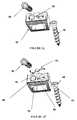
- FIGS. 1A-Gillustrate an embodiment of an anterior cervical intervertebral cage/BDFT screw construct in top ( FIG. 1A ), bottom isometric ( FIG. 1B ), side ( FIG. 1C ), isometric front ( FIG. 1D ), isometric bottom; partially exploded ( FIG. 1E ), isometric bottom; fully exploded ( FIG. 1F ), and isometric fully exploded with visualized internalized angled screw guides ( FIG. 1G ) views.
- FIGS. 2A-Gillustrate an embodiment of an anterior lumbar intervertebral cage/BDFT screw construct in top ( FIG. 2A ), bottom ( FIG. 2B ), front ( FIG. 2C ), side ( FIG. 2D ), isometric side ( FIG. 2E ), partially exploded top ( FIG. 2F ), and fully exploded top ( FIG. 2G ) views.
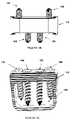
- FIGS. 3A-Fillustrate an embodiment of a posterior lumbar intervertebral cage/BDFT construct in top ( FIG. 3A ), front ( FIG. 3B ), side ( FIG. 3C ), isometric ( FIG. 3D ), partially exploded ( FIG. 3E ), and fully exploded ( FIG. 3F ) views.
- FIGS. 4A-Billustrate an embodiment of a posterior lumbar facet staple, flexure spring embodiment in side isometric ( FIG. 4A ) and exploded ( FIG. 4B ) views.
- FIGS. 5A-Cillustrate an embodiment of a posterior lumbar facet staple, torsional spring embodiment in side isometric ( FIG. 5A ), bottom isometric ( FIG. 5B ), and exploded ( FIG. 5C ) views.
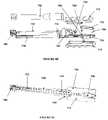
- FIGS. 6A-Cillustrate an embodiment of a Lumbar facet joint staple gun in side ( FIG. 6A ), exploded ( FIG. 6B ) and cross-sectional ( FIG. 6C ) views.
- FIGS. 7A-Billustrate an embodiment of a posterior cervical facet joint staple, two pronged ( FIG. 7A ) and four pronged ( FIG. 7B ) embodiments.
- FIGS. 8A-Eillustrate an embodiment of a posterior cervical facet staple gun in top-side ( FIG. 8A ), oblique ( FIG. 8B ), top ( FIG. 8C ), exploded ( FIG. 8D ), and cut-away ( FIG. 8E ) views.
- FIGS. 1A-8Eexemplary embodiments of the invention will now be described.
- the above described problems of the conventional artcan be solved in the cervical, thoracic and lumbosacral spines by insertion into the denuded intervertebral disc space multiple embodiments of a bi-directional fixating transvertebral (BDFT) screw/cage apparatus.
- BDFTbi-directional fixating transvertebral
- FIGS. 1A-Gillustrate three-dimensional views of an embodiment of an anterior cervical intervertebral cage/BDFT construct.
- the cage 10is elliptically contoured ( FIG. 1C ; side view) to fit into the bi-concave cervical disc space.
- the embodimentincludes two screws 30 , 40 .
- a first screw 30is oriented rostrally (superiorly) and a second screw 40 is oriented caudally (inferiorly).
- the cage 10can include a cavity 60 for bone product placement.
- the cage 10includes two built in internalized screw/drill guides 80 , 82 (e.g., preferably having a 25 degree angulation), one for each screw 30 , 40 , which orient the screws 30 , 40 bi-directionally in opposite directions.
- the internalized screw/drill guides 80 , 82can have different degrees of angulation and/or different positions within the cage 10 .
- the built in tunnels of the screw guides 80 , 82provide an important advantage of ensuring that only one prescribed angled trajectory is possible for transvertebral screw placement.
- Embodiments of the intervertebral cagescan be designed with internalized screw/drill guides with different angles and/or different positions within the cage.
- the angle and size of the screwsmake them amenable to single or multi-level placement.
- the superior and inferior surfaces or edges of the lumbar cagecan include ridges 50 to facilitate integration and fusion with superior and inferior vertebral bodies.
- the longitudinal ends or sides of the cage 10each include a groove or slot 15 formed therein that is adjacent to an edge of an upper surface of the intervertebral cage 10 .
- the slot 15can engage a screw guide of a tool, such as an insertions tool.
- the embodimentalso includes a screw locking mechanism 20 which can be, for example, press-fit to the top of the cage 10 .
- the top of the cage 10can include a perforation 90 and/or an indentation 70 for each locking mechanism 20 .
- Each locking mechanism 20also can be designed to rest and be press-fit into the superior surface of the in-built self drilling screw guides 80 , 82 .
- the screw locking mechanism 20can be manufactured from a variety of materials, such as titanium. When the screws 30 , 40 are turned into the screw locking mechanism 20 , the screws lock by mechanically indenting the screw locking mechanism 20 , thereby preventing back-out or pull-out.
- the locking mechanism 20can be reused for a limited number of cycles.
- the locking mechanism 20is an evolutionary advance and improvement compared to the apparatus illustrated in the aforementioned related applications.
- the novel embodiments of the present inventionare quite unique and different from all other conventional locking mechanisms used for other types of anterior cervical plates. No other conventional anterior cervical intervertebral cage/BDFT screw constructs are known.
- FIGS. 2A-Gillustrate three-dimensional views of an embodiment of an anterior lumbar intervertebral cage/BDFT construct.
- the cage 110is larger than the cervical cage 10 and is also elliptically contoured to fit into the bi-concave lumbar disc space ( FIG. 2D ; side view).
- the cage 110includes four (4) horizontally aligned internalized screw guides 190 , 192 for four (4) screws 130 , 140 , 150 , 160 .
- the two lateral (left and right) screwsare oriented inferiorly, and the two middle screws are oriented superiorly.
- the orientations of the four screw guides 190 , 192 (and screws; 130 , 140 , 150 , 160 )are selected because of their symmetry and inherent stability.
- the cage 110can include a large cavity 180 for bone product placement.
- the cage 110includes four built-in internalized screw/drill guides 190 , 192 (e.g., having a preferred 25 degree angulation), one for each screw.
- Other embodiments of the intervertebral cage 110can be designed with internalized screw/drill guides 190 , 192 with different angles and/or different positions within the cage 110 .
- the angle and size of the screwsmake them amenable to single or multi-level placement.
- the superior and inferior surfaces or edges of the cage 110can include ridges 170 to facilitate integration and fusion with superior and inferior vertebral bodies. In an embodiment, there are no compartmental divisions in the cavity 180 for bone product placement to maximize the quantity of bone for fusion.
- the cage 110includes two screw locking mechanisms 120 that can be, for example, press-fit to the top of the cage 110 .
- one locking mechanismcan be provided for each screw, or one locking mechanism can be provided for two or more screws.
- the top of the cage 110can include a perforation 194 and/or an indentation 196 for each locking mechanism 120 .
- Each locking mechanism 120also can be designed to rest and be press-fit into the in-built self drilling screw guides 190 , 192 .
- the locking mechanism 120can be manufactured from a variety of materials, such as titanium. When the screws are turned into the screw locking mechanism 120 , they lock by mechanically indenting the screw locking mechanism 120 .
- the locking mechanism 120can be reused for a limited number of cycles.
- This locking mechanism 120is an evolutionary advance and improvement compared to the apparatus illustrated in the aforementioned related applications.
- the novel locking mechanism 120also is quite unique and different from all other conventional locking mechanisms used for other types of anterior lumbar cages.
- U.S. Pat. No. 4,904,261John Dove, Philip H. Hardcastle, John K. Davis and Brian King.
- the '261 patentdiscloses a horseshoe implant having a plurality of cylindrical holes with smooth inner surfaces and comprise only one stop for the heads of the bone screws to be inserted into them. The placement of five cylindrical holes is oriented within the cage in a non-symmetric manner.
- the embodiments of the present inventiondiffer in many substantial ways from the conventional devices.
- the present inventionprovides a symmetric orientation of the screw holes, as well as a screw locking mechanism.
- the present inventionalso describes an angulation/trajectory (e.g., a preferred angulation/trajectory) for preventing pull-out or back-out of the screws that would make placement of all screws in a manner which would lead to maximum stability of the construct within the vertebral space, and obviate the need for external drill guides, and surgeon trajectory angulation guess work.
- the anterior lumbar construct of the present inventiondiffers in many substantial ways from the conventional devices.
- the present inventionincludes a single cage construct with four (4) internalized drill guides arranged horizontally in a row.
- the middle two screwsare oriented superiorly, and the lateral left and right screws are oriented inferiorly.
- This symmetric alignment of screws and orientations within the superior and inferior vertebral bodiesmake the fixation to the superior and inferior vertebral bodies much more symmetric and thus more stable.
- the cageincludes a screw guide having a predetermined trajectory (e.g., a preferred trajectory of 25 degrees) that makes placement of all screws equally facile, more amenable to multi-level placement, and diminishes the need for external drill guides.
- a predetermined trajectorye.g., a preferred trajectory of 25 degrees
- the exemplary screw locking mechanismwhich is press-fit to the cage, is unique and differs substantially from the conventional approach of matching screw/cage threads or spiral springs.
- FIGS. 3A-Fillustrate three-dimensional views of an embodiment of a posterior lumbar intervertebral cage/BDFT construct.
- the screws 230 , 240perforate and orient in opposing superior and inferior directions.
- the cage 210can include a cavity 250 for bone product placement.
- the top and bottom portions of the cage 210are elliptically contoured to naturally fit into the bi-concave intervertebral disc space ( FIG. 3C ; side view).
- the cage 210includes built-in internalized screw/drill guides 270 , 280 having a predetermined angled trajectory (e.g., having a preferred 25 degree angulation).
- the intervertebral cages 210can be designed with internalized screw/drill guides 270 , 280 with different angles and/or different positions within the cage 210 .
- the angle and size of the screws 230 , 240make them amenable to single or multi-level placement.
- the superior and inferior surfaces or edgescan include ridges 260 to facilitate integration and fusion with superior and inferior vertebral bodies.
- One of these constructsis placed posteriorly into the intervertebral space on the left side, and the other on the right side.
- the cage 210includes a screw locking mechanism 220 that can be, for example, press-fit to the top of the cage 210 .
- the top of the cage 210can have a perforation 290 and/or an indentation 292 to engage the locking mechanism 220 .
- the locking mechanism 220also can be designed to rest and be press-fit into the in-built self drilling screw guides 270 , 280 .
- the locking mechanism 220can be manufactured from a variety of materials, such as titanium. When the screws 230 , 240 are turned into the screw locking mechanism 220 , they lock by mechanically indenting the screw locking mechanism 220 . They can be reused for a limited number of cycles.
- the exemplary embodiment of the locking mechanism 220is an evolutionary advance and improvement compared to the apparatus illustrated in the aforementioned related applications.
- the novel locking mechanism 220also is quite unique and different from other conventional locking mechanisms used for other known cervical and lumbar anterior or posterior plate screws. No other conventional posterior lumbar intervertebral cage BDFT/screw constructs are known.
- FIGS. 4A-Billustrate an embodiment of a posterior lumbar facet staple having a flexure spring.
- FIGS. 5A-Cillustrate an embodiment of a lumbar facet staple having a torsional spring.
- the embodiments illustrated in the related applicationsincluded a ratchet.
- the staplecould be incrementally closed with increased ratcheting over increasing number of spurs.
- the present inventionprovides two evolved embodiments, which are superior to conventional designs in that the closing mechanisms can withstand much greater force (Newtons) than a small external ratchet. Other improvements will be described below.
- FIGS. 4A-Billustrate an embodiment of a posterior lumbar facet staple 500 having a flexure spring 530 .
- the features of the staple 500include top claws 510 and bottom claws 520 with ridges 570 to help incorporate and fuse with bone.
- a staple pin (pivot) 560connects the top claws 510 and bottom claws 520 .
- the staple 500includes four fastener pins (prongs) 580 , 582 , 584 , 586 , two per top claw 510 or bottom claw 520 .
- Ratchet teeth 540are molded onto the lower claw 520 , and a spring loaded ratchet pawl 530 pivots on the claw, and locks the staple 500 in position.
- the ratchet 540works in standard fashion.
- the ratchet pawle.g., the flexure spring
- the ratchet spring 530acts as a spring due to its curvature. So depending on the material used for the ratchet spring, the ratchet spring 530 can deform more or less, thereby providing different degrees of resistance.
- the ratchet mechanism 540limits the opening force of the staple 500 by a force proportional to the stiffness of the flexure spring 530 (e.g., ratchet pawl).
- the forcecan be tailored by making the pawl from different materials or varying the dimension of the flexure spring on the pawl. This embodiment can achieve significant rigidity (stiffness).
- FIGS. 5A-Cillustrate an embodiment of a posterior lumbar facet staple 600 having a torsional spring 630 .
- FIGS. 5A-Cillustrate features of the staple 600 , which include top claws 610 and bottom claws 620 with ridges 670 to help incorporate and fuse with bone.
- a staple pin (pivot) 660joins the upper claw 610 and lower claw 620 of the staple 600 .
- the staple 600includes four fastener pins (prongs) 682 , 684 , 686 , 688 , two per top claw 610 or bottom claw 620 of the staple 600 .
- the features of the staple 600include a torsional spring 630 , a brake 680 , and a pivot spring pin 640 .
- the ratchetworks in standard fashion.
- the springdoes not interfere with the motion.
- a ratchet mechanism(brake) 680 that engages with the spring 630 .
- the force required to open the staple 600will depend on the stiffness of the spring 630 .
- Having staple models with different types of springsallows the tailoring of different staples to the needs of a given patient.
- the embodiments of the present inventionhave less compliance than the conventional devices.
- FIGS. 6A-6Cillustrate an embodiment of a lumbar facet joint staple gun 700 .
- the exemplary staple gun 700is an evolutionary advanced version compared to the conventional designs.
- An improved feature of the staple gun 700includes a spring return 274 to bring the handles (e.g., upper and lower grips 712 , 714 ) back to their original position after stapling, and a pull knob that opens the staple fingers (e.g., claws) to release the staple 760 at will.
- the staple 760 in this embodimentis released automatically when it is closed.
- a return spring 774is added to the handles (e.g., upper and lower grips 712 , 714 ) so that the user does not have to reset the stapler manually each time it is used.
- the figuresillustrate the staple gun 700 , which includes two upper and lower grips 712 , 714 , upper and lower bars 722 , 724 , a cylinder 750 , an opening connector 740 , an opening rod 772 , an opening lever or pull knob 730 , a puller 726 , a connector 740 , a return spring 774 , and pins 790 , 792 , 794 .
- FIGS. 7A and 7Billustrate embodiments of two pronged and four pronged posterior cervical facet joint staples 800 respectively.
- cervical facet joint stapleshave been thoroughly described in the aforementioned related applications, the relevant portions of which are hereby incorporated by reference in their entirety. The evolutionary advance and improvements of the present invention will now be described.
- an exemplary posterior cervical facet joint staple 800includes a staple body extending along a longitudinal axis.
- the bodyincludes a plurality of prongs (e.g., first prong 810 and second prong 820 ) extending from a lower surface of the staple body.
- the lower surface of the staple bodyalso includes a groove 830 for engaging or fitting into the spring supports of a staple gun (e.g., a cervical staple gun, as described in more detail below).
- the groove 830extends along an axis that is perpendicular to the longitudinal axis of the staple body.
- the groove 830is disposed at a center point along the longitudinal axis.
- FIG. 7Aillustrates a two-prong embodiment
- FIG. 7Billustrates a four-prong embodiment.
- the exemplary embodiment of a staple gun 900incorporates the staple 960 into the facet joints with much greater force than conventional methods of staple incorporation by use of a staple impactor.
- the speed and strength of staple placementmakes the present invention more amenable to percutaneous non-invasive surgical application.
- FIGS. 8A-Eillustrate an embodiment of a posterior cervical facet staple gun 900 .
- the internal mechanismincludes a handle 910 having a socket head cap screw 948 , a staple guide 940 , and a staple plunger 920 .
- a staple 960is held in place at the tip of the staple guide 940 by two spring supports 942 , 944 located on each side of the tip of the guide 940 .
- the staple plunger 920sits behind the staple 960 and it is spring loaded by a torsional spring 932 .
- the torsional spring 932is compressed and held in place by a spring hook 922 connected to the staple trigger 930 via a linkage mechanism 928 .
- the linkage mechanism 928rotates the spring hook 922 releasing the torsional spring 932 .
- the torsional spring 932then pushes on the staple plunger 920 which subsequently presses on the back of the staple 960 with increasing force.
- the staple 960is momentarily compressed between the plunger 920 and spring supports 942 , 944 and develops enough momentum to shoot out of the guide 940 with enough force to penetrate the bone.
- the userTo reload the stapler 900 , the user simply pulls on the thumb hook at the end of the plunger 920 until the spring hook 922 catches the torsional spring 932 . Once the plunger 920 is locked, the user can place another staple 960 at the tip of the staple guide 940 .
- a soft polymer (e.g., foam) pad 924acts as a return spring for the trigger 930 .
- One end of the torsional spring 932is clamped to the handle 910 by a bracket (e.g., spring clamp) 936 .
- the handle 910is made of two symmetrical pieces 912 , 914 joined by screws 916 .
- Anterior cervical spine placement of the intervertebral cage/BDFT screw construct( FIG. 1 ) can be implanted via previously described techniques for anterior cervical discectomy and fusion. Some but not all of these techniques include, open, microscopic, closed endoscopic or tubular. Fluoroscopic or any other form of visualized guidance can be used for this procedure.
- the patientis placed in a supine position.
- An incisionis made overlying the intended disc space or spaces, and the anterior spine is exposed.
- a discectomyis performed and the endplates exposed.
- the disc heightis measured and an anterior cervical intervertebral cage of the appropriate disc height, width and depth is selected.
- the central cavityis packed with bone fusion material, autologous bone graft, allograft, alone or in combination with any commercially available bone fusion promoting product.
- the cageis then inserted into the midline of the anterior disc space routinely until it is flush or countersunk relative to the vertebral body above and below.
- the BDFT screwsare then inserted into the internalized rostrally (superiorly) and caudally (inferiorly) angled screw guides.
- a drill with or without a drill guidecan be used to prepare for screw placement. This is not absolutely necessary.
- the cagehas internalized screw guides, self-drilling/self-tapping screws of the appropriately selected lengths can be directly screwed into the vertebral bodies once placed into the internalized drill-guided angled tunnels.
- the cage's screw guideswhich have internalized tunnels, direct the screws into the superior and inferior vertebral bodies in the predetermined angle of the internalized tunnels. There is no other angled trajectory other than that which is built into the internalized screw guide/tunnel of the cage that the screw can be oriented in. Hence, there is no absolute need for fluoroscopic guidance.
- the BDFT screwscan then be locked into their final positions by the last several turns which embed them into the screw locking mechanism thereby preventing screw blackout. If the surgeon changes his mind intra-operatively or if in a future date the construct needs to be removed, the screws can be backed out.
- the locking mechanismhas several cycles of use, and thus screws once backed out, can be re-screwed and re-locked. Multiple level placements can be performed including two, three or more levels if necessary.
- FIG. 2Anterior or anteriolateral placement of thoracic or lumbar spine intervertebral cage/BDFT screw constructs ( FIG. 2 ) can be implanted via previously described surgical techniques for anterior lumbar discectomy, and transthoracic, anterior-lateral thoracic discectomy. Some but not all of these techniques include, open, microscopic, closed endoscopic or tubular. Fluoroscopic or any other form of visualized guidance can be used for this procedure.
- a discectomyis performed and the endplates exposed.
- the disc heightis measured and an anterior lumbar (or thoracic) intervertebral cage of the appropriate disc height, width and depth is selected.
- the central cavityis packed with bone fusion material, autologous bone graft, allograft, alone or in combination with any commercially available bone fusion promoting product.
- the cageis then inserted into the midline of the anterior disc space routinely until it is flush or countersunk relative to the vertebral body above and below.
- the four BDFT screwsare then inserted into the two middle internalized rostrally (superiorly) and two lateral, caudally (inferiorly) angled screw guides.
- a drill with or without a drill guidecan be used to prepare for screw placement. This is not absolutely necessary. Because the cage has internalized screw guides, self-drilling/self-tapping screws of the appropriately selected lengths can be directly screwed into the vertebral bodies once placed into the internalized drill-guided angled tunnels.
- the cage's internalized guideswhich have internalized tunnels, direct the screws into the superior and inferior vertebral bodies in the predetermined angle of the internalized tunnels. There is no other angled trajectory other than that which is built into the internalized screw guide/tunnel of the cage that the screw can be oriented in. Hence there is no absolute need for fluoroscopic guidance.
- the BDFT screwscan then be locked into their final positions by the last several turns which embed them into the screw locking mechanism thereby preventing screw blackout. If the surgeon changes his mind intra-operatively or if in a future date the construct needs to be removed, the screws can be backed out.
- the locking mechanismhas several cycles of use, and thus screws once backed out, can be re-screwed and re-locked. Multiple level placements can be performed including two, three or more levels if necessary.
- Implantation of the posterior lumbar intervertebral cage/BDFT screw constructscan be performed via previously described posterior lumbar interbody fusion (PLIF) or posterior transforaminal lumbar interbody fusion (TLIF) procedures.
- the procedurescan be performed open, microscopic, closed tubular or endoscopic techniques. Fluoroscopic guidance can be used with any of these procedures.
- the patientis placed in the prone position.
- a midline incisionis made for a PLIF procedure, and one or two parallel paramedian incisions or a midline incision is made for the TLIF procedure.
- a unilateral or bilateral facet sparing hemi-laminotomyis created to introduce the posterior lumbar construct into the disc space after a discectomy is performed and the space adequately prepared.
- the far lateral disc spaceis entered and a circumferential discectomy is performed.
- the disc spaceis prepared and the endplates exposed.
- the disc heightis measured and a posterior lumbar intervertebral cage/BDFT screw construct ( FIG. 3 ) of the appropriate disc height, width and depth is selected.
- the central cavityis packed with bone fusion material, autologous bone graft, allograft, alone or in combination with any commercially available bone fusion promoting product.
- one constructis placed on either right or left sides, or one construct each is placed into left and right sides.
- the constructsare inserted such they are flush or countersunk relative to the superior and inferior vertebral bodies.
- the intervertebral space in between the constructscan also be packed with bone product for fusion.
- the BDFT screwsare then inserted into internalized rostrally (superiorly) and caudally (inferiorly) angled screw guides.
- a drill with or without a drill guidecan be used to prepare for screw placement. This is not absolutely necessary.
- self-drilling/self-tapping screws of the appropriately selected lengthscan be directly screwed into the vertebral bodies once placed into the internalized drill-guided angled tunnels.
- the cage's internalized guideswhich have internalized tunnels, direct the screws into the superior and inferior vertebral bodies in the predetermined angle of the internalized tunnels.
- the BDFT screwscan then be locked into their final positions by the last several turns which embed them into the screw locking mechanism thereby preventing screw backout. If the surgeon changes his mind intra-operatively or if in a future date the construct needs to be removed, the screws can be backed out.
- the locking mechanismhas several cycles of use, and thus screws once backed out, can be re-screwed and re-locked. Multiple level placements can be performed including two, three or more levels.
- FIGS. 4 and 5The surgical placement of the lumbar facet staples ( FIGS. 4 and 5 ) via a posterior facet lumbar staple gun ( FIG. 6 ) is described in the aforementioned related applications.
- the surgical procedure for these staple embodiments with this staple gun embodimentis identical to that which has been previously described.
- the evolutionary advantages of these embodimentsare explained above.
- the patientis flipped prone and his head and neck secured.
- a single midline or two paramedian incisionsare made for unilateral or bilateral or multilevel placement of cervical staples.
- the facet jointis exposed. Alternatively and preferably this can be performed percutaneously under fluoroscopic guidance with IV sedation.
- the cervical staple, two or four prongedis loaded either into the two or four pronged staple gun, is placed on the two articulating cervical facets, and then stapled into the joint using the staple gun.
- cervical facet staplescan be inserted ranging from a single unilateral two pronged staple providing a high degree of flexibility to a total of four bilaterally placed four pronged cervical staples leading to the highest degree of rigidity per cervical posterior joint. Additional bone may or may not be placed in the vicinity to facilitate permanent and solid fusion.
- This evolved cervical staple guncompared to our prior staple impactor makes this procedure more amenable to percutaneous, and more precise staple placement, as well as more contoured staple-bone integration.
- the present inventionsmay provide effective and safe techniques that overcome the problems associated with current transpedicular based cervical, thoracic and lumbar fusion technology, as well as anterior cervical, thoracic and lumbar plating technology, and for many degenerative stable and unstable spinal diseases. These inventions could replace much pedicle screw, and anterior plating based instrumentation in many but not all degenerative spine conditions.
- posterior cervical and lumbar facet staplesThe speed and simplicity of placement of posterior cervical and lumbar facet staples, placement of anterior and posterior lumbar intervertebral cage/BDFT screw constructs, and placement of anterior cervical cage/BDFT screw constructs far exceeds that of current pedicle screw and anterior spinal plating technology. Furthermore, these devices have markedly significantly decreased risk of misguided screw placement and hence decreased risk of neurovascular injury, and blood loss.
- intervertebral cage/BDFT screw constructs and facet staplescould be applied modularly in different combinations to achieve different degrees of rigidity (flexibility).
- the posterior cervical and lumbar staple technologyis amenable to short same-day procedures performed under local IV anesthesia with a rapid recovery time.
- the lumbar and cervical intervertebral cage/BDFT screw constructsall would have decreased recovery time, and more rapid return to work time compared to pedicle screw, and plating technology. These devices with great probability lead to similar if not equal fusion rates, with substantially less morbidity, and hence, overall, make them a major advance in the evolution of spinal instrumented technology leading to advances in the compassionate care of the spinal patient.
Landscapes
- Health & Medical Sciences (AREA)
- Orthopedic Medicine & Surgery (AREA)
- Life Sciences & Earth Sciences (AREA)
- Engineering & Computer Science (AREA)
- Biomedical Technology (AREA)
- Surgery (AREA)
- Neurology (AREA)
- Heart & Thoracic Surgery (AREA)
- Animal Behavior & Ethology (AREA)
- General Health & Medical Sciences (AREA)
- Public Health (AREA)
- Veterinary Medicine (AREA)
- Medical Informatics (AREA)
- Molecular Biology (AREA)
- Nuclear Medicine, Radiotherapy & Molecular Imaging (AREA)
- Transplantation (AREA)
- Vascular Medicine (AREA)
- Oral & Maxillofacial Surgery (AREA)
- Cardiology (AREA)
- Rheumatology (AREA)
- Physical Education & Sports Medicine (AREA)
- Prostheses (AREA)
- Surgical Instruments (AREA)
Abstract
Description
Claims (42)
Priority Applications (31)
| Application Number | Priority Date | Filing Date | Title |
|---|---|---|---|
| US12/054,335US7972363B2 (en) | 2005-04-12 | 2008-03-24 | Bi-directional fixating/locking transvertebral body screw/intervertebral cage stand-alone constructs and posterior cervical and lumbar interarticulating joint stapling guns and devices for spinal fusion |
| US12/471,340US8734516B2 (en) | 2005-04-12 | 2009-05-22 | Bi-directional fixating/locking transvertebral body screw/intervertebral cage stand-alone constructs having a central screw locking lever, and pliers and devices for spinal fusion |
| US12/471,345US8257370B2 (en) | 2005-04-12 | 2009-05-22 | Posterior cervical and lumbar interarticulating joint staples, stapling guns, and devices for spinal fusion |
| US12/957,776US9888918B2 (en) | 2005-04-12 | 2010-12-01 | Horizontal-transvertebral curvilinear nail-screws with inter-locking rigid or jointed flexible rods for spinal fusion |
| US13/101,129US8784450B2 (en) | 2005-04-12 | 2011-05-04 | Interarticulating spinous and transverse process staples for spinal fusion |
| US13/101,135US9675385B2 (en) | 2005-04-12 | 2011-05-04 | Spinous process staple with interdigitating-interlocking hemi-spacers for adjacent spinous process separation and distraction |
| US13/103,994US9603713B2 (en) | 2005-04-12 | 2011-05-09 | Bi-directional fixating/locking transvertebral body screw/intervertebral cage stand-alone constructs and posterior cervical and lumbar interarticulating joint stapling guns and devices for spinal fusion |
| US13/401,829US9744052B2 (en) | 2005-04-12 | 2012-02-21 | Bi-directional fixating/locking transvertebral body screw/intervertebral cage stand-alone constructs |
| US13/418,323US9814601B2 (en) | 2005-04-12 | 2012-03-12 | Bi-directional fixating/locking transvertebral body screw/intervertebral cage stand-alone constructs |
| US13/418,335US9532821B2 (en) | 2005-04-12 | 2012-03-12 | Bi-directional fixating/locking transvertebral body screw/intervertebral cage stand-alone constructs with vertical hemi-bracket screw locking mechanism |
| US14/257,650US9622875B2 (en) | 2005-04-12 | 2014-04-21 | Bi-directional fixating/locking transvertebral body screw/intervertebral cage stand-alone constructs having a central screw locking lever, and pliers and devices for spinal fusion |
| US14/337,210US10098672B2 (en) | 2005-04-12 | 2014-07-21 | Cervical spinous process staple |
| US15/397,198US10098678B2 (en) | 2005-04-12 | 2017-01-03 | Bi-directional fixating/locking transvertebral body screw/intervertebral cage stand-alone constructs with vertical hemi-bracket screw locking mechanism |
| US15/490,107US10064738B2 (en) | 2005-04-12 | 2017-04-18 | Bi-directional fixating/locking transvertebral body screw/intervertebral cage stand-alone constructs having a central screw locking lever, and pliers and devices for spinal fusion |
| US15/678,401US10238505B2 (en) | 2005-04-12 | 2017-08-16 | Bi-directional fixating/locking transvertebral body screw/intervertebral cage stand-alone constructs |
| US15/693,594US10149703B2 (en) | 2005-04-12 | 2017-09-01 | Cervical spinous process staple |
| US15/791,484US10376383B2 (en) | 2005-04-12 | 2017-10-24 | Bi-directional fixating/locking transvertebral body screw/intervertebral cage stand-alone constructs |
| US15/862,016US10028740B2 (en) | 2005-04-12 | 2018-01-04 | Spinal fusion implant with curvilinear nail-screws |
| US16/042,163US10258329B2 (en) | 2005-04-12 | 2018-07-23 | Spinal fusion implant with curvilinear nail-screws |
| US16/100,410US10603183B2 (en) | 2005-04-12 | 2018-08-10 | Bi-directional fixating/locking transvertebral body screw/intervertebral cage stand-alone constructs having a central screw locking lever, and pliers and devices for spinal fusion |
| US16/160,937US10722274B2 (en) | 2005-04-12 | 2018-10-15 | Cervical spinous process staple |
| US16/160,824US10842542B2 (en) | 2005-04-12 | 2018-10-15 | Spinal bone fusion system |
| US16/362,294US10925753B2 (en) | 2005-04-12 | 2019-03-22 | Bi-directional fixating/locking transvertebral body screw/intervertebral cage stand-alone constructs |
| US16/384,232US20190328384A1 (en) | 2005-04-12 | 2019-04-15 | Spinal fusion implant with curvilinear nail-screws |
| US16/532,033US11141288B2 (en) | 2005-04-12 | 2019-08-05 | Bi-directional fixating/locking transvertebral body screw/intervertebral cage stand-alone constructs |
| US16/829,246US11229525B2 (en) | 2005-04-12 | 2020-03-25 | Bi-directional fixating/locking transvertebral body screw/intervertebral cage stand-alone constructs having a central screw locking lever, and pliers and devices for spinal fusion |
| US16/952,241US11759243B2 (en) | 2005-04-12 | 2020-11-19 | Spinal bone fusion system |
| US17/180,021US11918207B2 (en) | 2005-04-12 | 2021-02-19 | Spinal fusion implant |
| US17/181,706US20210307925A1 (en) | 2005-04-12 | 2021-02-22 | Bi-directional fixating/locking transvertebral body screw/intervertebral cage stand-alone constructs |
| US17/492,996US12144743B2 (en) | 2005-04-12 | 2021-10-04 | Intervertebral implant |
| US17/577,722US12232973B2 (en) | 2005-04-12 | 2022-01-18 | Intervertebral internal screw guide and fixation apparatus including screw lock |
Applications Claiming Priority (5)
| Application Number | Priority Date | Filing Date | Title |
|---|---|---|---|
| US67023105P | 2005-04-12 | 2005-04-12 | |
| US11/208,644US7704279B2 (en) | 2005-04-12 | 2005-08-23 | Bi-directional fixating transvertebral body screws, zero-profile horizontal intervertebral miniplates, expansile intervertebral body fusion devices, and posterior motion-calibrating interarticulating joint stapling device for spinal fusion |
| US11/536,815US7846188B2 (en) | 2005-04-12 | 2006-09-29 | Bi-directional fixating transvertebral body screws, zero-profile horizontal intervertebral miniplates, total intervertebral body fusion devices, and posterior motion-calibrating interarticulating joint stapling device for spinal fusion |
| US11/842,855US7942903B2 (en) | 2005-04-12 | 2007-08-21 | Bi-directional fixating transvertebral body screws and posterior cervical and lumbar interarticulating joint calibrated stapling devices for spinal fusion |
| US12/054,335US7972363B2 (en) | 2005-04-12 | 2008-03-24 | Bi-directional fixating/locking transvertebral body screw/intervertebral cage stand-alone constructs and posterior cervical and lumbar interarticulating joint stapling guns and devices for spinal fusion |
Related Parent Applications (4)
| Application Number | Title | Priority Date | Filing Date |
|---|---|---|---|
| US11/842,855Continuation-In-PartUS7942903B2 (en) | 2005-04-12 | 2007-08-21 | Bi-directional fixating transvertebral body screws and posterior cervical and lumbar interarticulating joint calibrated stapling devices for spinal fusion |
| US11/842,855ContinuationUS7942903B2 (en) | 2005-04-12 | 2007-08-21 | Bi-directional fixating transvertebral body screws and posterior cervical and lumbar interarticulating joint calibrated stapling devices for spinal fusion |
| US11/842,855DivisionUS7942903B2 (en) | 2005-04-12 | 2007-08-21 | Bi-directional fixating transvertebral body screws and posterior cervical and lumbar interarticulating joint calibrated stapling devices for spinal fusion |
| US14/337,210Continuation-In-PartUS10098672B2 (en) | 2005-04-12 | 2014-07-21 | Cervical spinous process staple |
Related Child Applications (7)
| Application Number | Title | Priority Date | Filing Date |
|---|---|---|---|
| US12/471,340Continuation-In-PartUS8734516B2 (en) | 2005-04-12 | 2009-05-22 | Bi-directional fixating/locking transvertebral body screw/intervertebral cage stand-alone constructs having a central screw locking lever, and pliers and devices for spinal fusion |
| US12/471,345Continuation-In-PartUS8257370B2 (en) | 2005-04-12 | 2009-05-22 | Posterior cervical and lumbar interarticulating joint staples, stapling guns, and devices for spinal fusion |
| US12/471,345ContinuationUS8257370B2 (en) | 2005-04-12 | 2009-05-22 | Posterior cervical and lumbar interarticulating joint staples, stapling guns, and devices for spinal fusion |
| US13/084,543DivisionUS8353913B2 (en) | 2005-04-12 | 2011-04-11 | Bi-directional fixating transvertebral body screws and posterior cervical and lumbar interarticulating joint calibrated stapling devices for spinal fusion |
| US13/101,135Continuation-In-PartUS9675385B2 (en) | 2005-04-12 | 2011-05-04 | Spinous process staple with interdigitating-interlocking hemi-spacers for adjacent spinous process separation and distraction |
| US13/103,944DivisionUS8694226B2 (en) | 2010-06-01 | 2011-05-09 | Control apparatus for internal combustion engine, control method for internal combustion engine and non-transitory computer-readable recording medium |
| US13/103,994DivisionUS9603713B2 (en) | 2005-04-12 | 2011-05-09 | Bi-directional fixating/locking transvertebral body screw/intervertebral cage stand-alone constructs and posterior cervical and lumbar interarticulating joint stapling guns and devices for spinal fusion |
Publications (2)
| Publication Number | Publication Date |
|---|---|
| US20080177307A1 US20080177307A1 (en) | 2008-07-24 |
| US7972363B2true US7972363B2 (en) | 2011-07-05 |
Family
ID=39642026
Family Applications (8)
| Application Number | Title | Priority Date | Filing Date |
|---|---|---|---|
| US12/054,335Active2027-03-24US7972363B2 (en) | 2005-04-12 | 2008-03-24 | Bi-directional fixating/locking transvertebral body screw/intervertebral cage stand-alone constructs and posterior cervical and lumbar interarticulating joint stapling guns and devices for spinal fusion |
| US12/471,340Active2027-01-25US8734516B2 (en) | 2005-04-12 | 2009-05-22 | Bi-directional fixating/locking transvertebral body screw/intervertebral cage stand-alone constructs having a central screw locking lever, and pliers and devices for spinal fusion |
| US13/103,994Active2027-11-04US9603713B2 (en) | 2005-04-12 | 2011-05-09 | Bi-directional fixating/locking transvertebral body screw/intervertebral cage stand-alone constructs and posterior cervical and lumbar interarticulating joint stapling guns and devices for spinal fusion |
| US14/257,650Expired - LifetimeUS9622875B2 (en) | 2005-04-12 | 2014-04-21 | Bi-directional fixating/locking transvertebral body screw/intervertebral cage stand-alone constructs having a central screw locking lever, and pliers and devices for spinal fusion |
| US15/490,107Expired - LifetimeUS10064738B2 (en) | 2005-04-12 | 2017-04-18 | Bi-directional fixating/locking transvertebral body screw/intervertebral cage stand-alone constructs having a central screw locking lever, and pliers and devices for spinal fusion |
| US16/100,410Expired - LifetimeUS10603183B2 (en) | 2005-04-12 | 2018-08-10 | Bi-directional fixating/locking transvertebral body screw/intervertebral cage stand-alone constructs having a central screw locking lever, and pliers and devices for spinal fusion |
| US16/829,246Expired - LifetimeUS11229525B2 (en) | 2005-04-12 | 2020-03-25 | Bi-directional fixating/locking transvertebral body screw/intervertebral cage stand-alone constructs having a central screw locking lever, and pliers and devices for spinal fusion |
| US17/577,722Active2027-03-19US12232973B2 (en) | 2005-04-12 | 2022-01-18 | Intervertebral internal screw guide and fixation apparatus including screw lock |
Family Applications After (7)
| Application Number | Title | Priority Date | Filing Date |
|---|---|---|---|
| US12/471,340Active2027-01-25US8734516B2 (en) | 2005-04-12 | 2009-05-22 | Bi-directional fixating/locking transvertebral body screw/intervertebral cage stand-alone constructs having a central screw locking lever, and pliers and devices for spinal fusion |
| US13/103,994Active2027-11-04US9603713B2 (en) | 2005-04-12 | 2011-05-09 | Bi-directional fixating/locking transvertebral body screw/intervertebral cage stand-alone constructs and posterior cervical and lumbar interarticulating joint stapling guns and devices for spinal fusion |
| US14/257,650Expired - LifetimeUS9622875B2 (en) | 2005-04-12 | 2014-04-21 | Bi-directional fixating/locking transvertebral body screw/intervertebral cage stand-alone constructs having a central screw locking lever, and pliers and devices for spinal fusion |
| US15/490,107Expired - LifetimeUS10064738B2 (en) | 2005-04-12 | 2017-04-18 | Bi-directional fixating/locking transvertebral body screw/intervertebral cage stand-alone constructs having a central screw locking lever, and pliers and devices for spinal fusion |
| US16/100,410Expired - LifetimeUS10603183B2 (en) | 2005-04-12 | 2018-08-10 | Bi-directional fixating/locking transvertebral body screw/intervertebral cage stand-alone constructs having a central screw locking lever, and pliers and devices for spinal fusion |
| US16/829,246Expired - LifetimeUS11229525B2 (en) | 2005-04-12 | 2020-03-25 | Bi-directional fixating/locking transvertebral body screw/intervertebral cage stand-alone constructs having a central screw locking lever, and pliers and devices for spinal fusion |
| US17/577,722Active2027-03-19US12232973B2 (en) | 2005-04-12 | 2022-01-18 | Intervertebral internal screw guide and fixation apparatus including screw lock |
Country Status (1)
| Country | Link |
|---|---|
| US (8) | US7972363B2 (en) |
Cited By (121)
| Publication number | Priority date | Publication date | Assignee | Title |
|---|---|---|---|---|
| US20100057206A1 (en)* | 2008-09-02 | 2010-03-04 | Duffield William E | Intervertebral fusion implant |
| US20100217393A1 (en)* | 2009-02-20 | 2010-08-26 | Theofilos Charles S | Interbody fusion system with intervertebral implant retention assembly |
| US20110125271A1 (en)* | 1999-08-18 | 2011-05-26 | Intrinsic Therapeutics, Inc. | Method of performing an anchor implantation procedure within a disc |
| US20110196492A1 (en)* | 2007-09-07 | 2011-08-11 | Intrinsic Therapeutics, Inc. | Bone anchoring systems |
| US20110238184A1 (en)* | 1995-03-27 | 2011-09-29 | Thomas Zdeblick | Methods and instruments for interbody fusion |
| US20110295371A1 (en)* | 2005-04-12 | 2011-12-01 | Moskowitz Ahmnon D | Bi-directional fixating transvertebral body screws and posterior cervical and lumbar interarticulating joint calibrated stapling devices for spinal fusion |
| US20120010714A1 (en)* | 2005-04-12 | 2012-01-12 | Ahmnon D Moskowitz | Bi-directional fixating/locking transvertebral body screw/intervertebral cage stand-alone constructs and posterior cervical and lumbar interarticulating joint stapling guns and devices for spinal fusion |
| US20120029637A1 (en)* | 2010-08-02 | 2012-02-02 | Ragab Ashraf A | Rotatable Cam Lift for an Expandable Bone Cage |
| US8114082B2 (en) | 2005-12-28 | 2012-02-14 | Intrinsic Therapeutics, Inc. | Anchoring system for disc repair |
| US8231678B2 (en) | 1999-08-18 | 2012-07-31 | Intrinsic Therapeutics, Inc. | Method of treating a herniated disc |
| US8257439B2 (en) | 2004-12-22 | 2012-09-04 | Ldr Medical | Intervertebral disc prosthesis |
| US8257437B2 (en)* | 1999-08-18 | 2012-09-04 | Intrinsic Therapeutics, Inc. | Methods of intervertebral disc augmentation |
| US8267999B2 (en) | 2002-11-05 | 2012-09-18 | Ldr Medical | Intervertebral disc prosthesis |
| US20120245693A1 (en)* | 2011-03-25 | 2012-09-27 | Josef Gorek | Spinal fixation device |
| US20120277870A1 (en)* | 2011-04-29 | 2012-11-01 | Wolters Madeline C | Spinal Interbody Implant With Bone Screw Retention |
| US8323341B2 (en) | 2007-09-07 | 2012-12-04 | Intrinsic Therapeutics, Inc. | Impaction grafting for vertebral fusion |
| US20120330419A1 (en)* | 2005-04-12 | 2012-12-27 | Moskowitz Nathan C | Bi-directional fixating/locking transvertebral body screw/intervertebral cage stand-alone constructs |
| US8343219B2 (en) | 2007-06-08 | 2013-01-01 | Ldr Medical | Intersomatic cage, intervertebral prosthesis, anchoring device and implantation instruments |
| US20130018470A1 (en)* | 2005-04-12 | 2013-01-17 | Moskowitz Nathan C | Bi-directional fixating/locking transvertebral body screw/intervertebral cage stand-alone constructs with vertical hemi-bracket screw locking mechanism |
| US20130023992A1 (en)* | 2005-04-12 | 2013-01-24 | Moskowitz Nathan C | Bi-directional fixating/locking transvertebral body screw/intervertebral cage stand-alone constructs |
| US8465546B2 (en) | 2007-02-16 | 2013-06-18 | Ldr Medical | Intervertebral disc prosthesis insertion assemblies |
| US8721723B2 (en) | 2009-01-12 | 2014-05-13 | Globus Medical, Inc. | Expandable vertebral prosthesis |
| US8753396B1 (en) | 2010-09-13 | 2014-06-17 | Theken Spine, Llc | Intervertebral implant having back-out prevention feature |
| US8771284B2 (en) | 2005-11-30 | 2014-07-08 | Ldr Medical | Intervertebral disc prosthesis and instrumentation for insertion of the prosthesis between the vertebrae |
| US8776456B1 (en)* | 2013-10-21 | 2014-07-15 | Sunmodo Corporation | Solar panel tile roof mounting device |
| US8858635B2 (en) | 2004-02-04 | 2014-10-14 | Ldr Medical | Intervertebral disc prosthesis |
| US8974532B2 (en) | 2004-04-28 | 2015-03-10 | Ldr Medical | Intervertebral disc prosthesis |
| US8979928B2 (en) | 2010-01-13 | 2015-03-17 | Jcbd, Llc | Sacroiliac joint fixation fusion system |
| US8979932B2 (en) | 2005-09-23 | 2015-03-17 | Ldr Medical | Intervertebral disc prosthesis |
| US9039774B2 (en) | 2012-02-24 | 2015-05-26 | Ldr Medical | Anchoring device and system for an intervertebral implant, intervertebral implant and implantation instrument |
| US9044337B2 (en) | 2009-12-31 | 2015-06-02 | Ldr Medical | Anchoring device and system for an intervertebral implant, intervertebral implant and implantation instrument |
| US9078765B2 (en) | 2001-07-13 | 2015-07-14 | Ldr Medical | Vertebral cage device with modular fixation |
| US9155631B2 (en) | 2010-04-08 | 2015-10-13 | Globus Medical Inc. | Intervertbral implant |
| US9333090B2 (en) | 2010-01-13 | 2016-05-10 | Jcbd, Llc | Systems for and methods of fusing a sacroiliac joint |
| US9333095B2 (en) | 2001-05-04 | 2016-05-10 | Ldr Medical | Intervertebral disc prosthesis, surgical methods, and fitting tools |
| US9381045B2 (en) | 2010-01-13 | 2016-07-05 | Jcbd, Llc | Sacroiliac joint implant and sacroiliac joint instrument for fusing a sacroiliac joint |
| US9463091B2 (en) | 2009-09-17 | 2016-10-11 | Ldr Medical | Intervertebral implant having extendable bone fixation members |
| US9474621B2 (en) | 2010-04-12 | 2016-10-25 | Globus Medical, Inc. | Expandable vertebral implant |
| US9554909B2 (en) | 2012-07-20 | 2017-01-31 | Jcbd, Llc | Orthopedic anchoring system and methods |
| US9572680B2 (en) | 2013-01-25 | 2017-02-21 | K2M, Inc. | Spinal implants, spinal implant kits, and surgical methods |
| US9675389B2 (en) | 2009-12-07 | 2017-06-13 | Samy Abdou | Devices and methods for minimally invasive spinal stabilization and instrumentation |
| US9700356B2 (en) | 2013-07-30 | 2017-07-11 | Jcbd, Llc | Systems for and methods of fusing a sacroiliac joint |
| US9707100B2 (en) | 2015-06-25 | 2017-07-18 | Institute for Musculoskeletal Science and Education, Ltd. | Interbody fusion device and system for implantation |
| US9707091B2 (en) | 2010-04-12 | 2017-07-18 | Globus Medical, Inc. | Expandable vertebral implant |
| US9713535B2 (en) | 2006-02-15 | 2017-07-25 | Ldr Medical | Transforaminal intersomatic cage for an intervertebral fusion graft and an instrument for implanting the cage |
| US9717539B2 (en) | 2013-07-30 | 2017-08-01 | Jcbd, Llc | Implants, systems, and methods for fusing a sacroiliac joint |
| US9757154B2 (en) | 2010-01-13 | 2017-09-12 | Jcbd, Llc | Systems and methods for fusing a sacroiliac joint and anchoring an orthopedic appliance |
| US9788961B2 (en) | 2010-01-13 | 2017-10-17 | Jcbd, Llc | Sacroiliac joint implant system |
| US9788971B1 (en) | 2013-05-22 | 2017-10-17 | Nuvasive, Inc. | Expandable fusion implant and related methods |
| US9801734B1 (en) | 2013-08-09 | 2017-10-31 | Nuvasive, Inc. | Lordotic expandable interbody implant |
| US9801546B2 (en) | 2014-05-27 | 2017-10-31 | Jcbd, Llc | Systems for and methods of diagnosing and treating a sacroiliac joint disorder |
| US9826986B2 (en) | 2013-07-30 | 2017-11-28 | Jcbd, Llc | Systems for and methods of preparing a sacroiliac joint for fusion |
| US9848993B2 (en) | 2005-04-12 | 2017-12-26 | Nathan C. Moskowitz | Zero-profile expandable intervertebral spacer devices for distraction and spinal fusion and a universal tool for their placement and expansion |
| US9877759B2 (en) | 2014-02-06 | 2018-01-30 | Life Spine, Inc. | Foot implant for bone fixation |
| US9877842B2 (en) | 2014-01-30 | 2018-01-30 | Ldr Medical | Anchoring device for a spinal implant, spinal implant and implantation instrumentation |
| US9889014B2 (en) | 2014-02-06 | 2018-02-13 | Life Spine, Inc. | Implant for bone fixation |
| US9913735B2 (en) | 2010-04-12 | 2018-03-13 | Globus Medical, Inc. | Angling inserter tool for expandable vertebral implant |
| US9937050B2 (en) | 2013-05-16 | 2018-04-10 | Ldr Medical | Vertebral implant, vertebral fastening device of the implant and implant instrumentation |
| US9943417B2 (en) | 2012-06-29 | 2018-04-17 | DePuy Synthes Products, Inc. | Lateral insertion spinal implant |
| US10039648B2 (en) | 2015-05-06 | 2018-08-07 | Choice Spine, Lp | Intervertebral implant device |
| US10076367B2 (en) | 2005-04-12 | 2018-09-18 | Moskowitz Family Llc | Bi-directional fixating transvertebral body screws, zero-profile horizontal intervertebral miniplates, total intervertebral body fusion devices, and posterior motion-calibrating interarticulating joint stapling device for spinal fusion |
| US10130489B2 (en) | 2010-04-12 | 2018-11-20 | Globus Medical, Inc. | Expandable vertebral implant |
| US10195053B2 (en) | 2009-09-18 | 2019-02-05 | Spinal Surgical Strategies, Llc | Bone graft delivery system and method for using same |
| US10245087B2 (en) | 2013-03-15 | 2019-04-02 | Jcbd, Llc | Systems and methods for fusing a sacroiliac joint and anchoring an orthopedic appliance |
| US10245159B1 (en) | 2009-09-18 | 2019-04-02 | Spinal Surgical Strategies, Llc | Bone graft delivery system and method for using same |
| US10299842B2 (en) | 2013-12-20 | 2019-05-28 | Crossroads Extremity Systems, Llc | Bone plates with dynamic elements |
| US10327910B2 (en) | 2013-03-14 | 2019-06-25 | X-Spine Systems, Inc. | Spinal implant and assembly |
| US10349982B2 (en) | 2011-11-01 | 2019-07-16 | Nuvasive Specialized Orthopedics, Inc. | Adjustable magnetic devices and methods of using same |
| US10426630B2 (en) | 2014-02-12 | 2019-10-01 | K2M, Inc. | Spinal implant |
| US10478310B2 (en) | 2014-05-06 | 2019-11-19 | Ldr Medical, S.A.S. | Vertebral implant, device for vertebral attachment of the implant and instrumentation for implantation thereof |
| US10478232B2 (en) | 2009-04-29 | 2019-11-19 | Nuvasive Specialized Orthopedics, Inc. | Interspinous process device and method |
| US10492841B2 (en) | 2014-07-10 | 2019-12-03 | Crossroads Extremity Systems, Llc | Bone implant and means of insertion |
| US10548740B1 (en) | 2016-10-25 | 2020-02-04 | Samy Abdou | Devices and methods for vertebral bone realignment |
| US10575961B1 (en) | 2011-09-23 | 2020-03-03 | Samy Abdou | Spinal fixation devices and methods of use |
| US10603185B2 (en) | 2004-02-04 | 2020-03-31 | Ldr Medical | Intervertebral disc prosthesis |
| US10603055B2 (en) | 2017-09-15 | 2020-03-31 | Jcbd, Llc | Systems for and methods of preparing and fusing a sacroiliac joint |
| US10617453B2 (en) | 2015-10-16 | 2020-04-14 | Nuvasive Specialized Orthopedics, Inc. | Adjustable devices for treating arthritis of the knee |
| US10646262B2 (en) | 2011-02-14 | 2020-05-12 | Nuvasive Specialized Orthopedics, Inc. | System and method for altering rotational alignment of bone sections |
| US10660675B2 (en) | 2010-06-30 | 2020-05-26 | Nuvasive Specialized Orthopedics, Inc. | External adjustment device for distraction device |
| US10695105B2 (en) | 2012-08-28 | 2020-06-30 | Samy Abdou | Spinal fixation devices and methods of use |
| US10729470B2 (en) | 2008-11-10 | 2020-08-04 | Nuvasive Specialized Orthopedics, Inc. | External adjustment device for distraction device |
| US10743794B2 (en) | 2011-10-04 | 2020-08-18 | Nuvasive Specialized Orthopedics, Inc. | Devices and methods for non-invasive implant length sensing |
| US10751094B2 (en) | 2013-10-10 | 2020-08-25 | Nuvasive Specialized Orthopedics, Inc. | Adjustable spinal implant |
| US10835290B2 (en) | 2015-12-10 | 2020-11-17 | Nuvasive Specialized Orthopedics, Inc. | External adjustment device for distraction device |
| US10857003B1 (en) | 2015-10-14 | 2020-12-08 | Samy Abdou | Devices and methods for vertebral stabilization |
| US10918425B2 (en) | 2016-01-28 | 2021-02-16 | Nuvasive Specialized Orthopedics, Inc. | System and methods for bone transport |
| US10918498B2 (en) | 2004-11-24 | 2021-02-16 | Samy Abdou | Devices and methods for inter-vertebral orthopedic device placement |
| US10945725B2 (en) | 2017-02-06 | 2021-03-16 | Crossroads Extremity Systems, Llc | Implant inserter |
| US10973648B1 (en) | 2016-10-25 | 2021-04-13 | Samy Abdou | Devices and methods for vertebral bone realignment |
| US10973656B2 (en) | 2009-09-18 | 2021-04-13 | Spinal Surgical Strategies, Inc. | Bone graft delivery system and method for using same |
| US11006982B2 (en) | 2012-02-22 | 2021-05-18 | Samy Abdou | Spinous process fixation devices and methods of use |
| US11173040B2 (en) | 2012-10-22 | 2021-11-16 | Cogent Spine, LLC | Devices and methods for spinal stabilization and instrumentation |
| US11179248B2 (en) | 2018-10-02 | 2021-11-23 | Samy Abdou | Devices and methods for spinal implantation |
| US11179149B2 (en) | 2017-02-07 | 2021-11-23 | Crossroads Extremity Systems, Llc | Counter-torque implant |
| US11191579B2 (en) | 2012-10-29 | 2021-12-07 | Nuvasive Specialized Orthopedics, Inc. | Adjustable devices for treating arthritis of the knee |
| US11202626B2 (en) | 2014-07-10 | 2021-12-21 | Crossroads Extremity Systems, Llc | Bone implant with means for multi directional force and means of insertion |
| US11202707B2 (en) | 2008-03-25 | 2021-12-21 | Nuvasive Specialized Orthopedics, Inc. | Adjustable implant system |
| US11234849B2 (en) | 2006-10-20 | 2022-02-01 | Nuvasive Specialized Orthopedics, Inc. | Adjustable implant and method of use |
| US11246694B2 (en) | 2014-04-28 | 2022-02-15 | Nuvasive Specialized Orthopedics, Inc. | System for informational magnetic feedback in adjustable implants |
| US11317951B2 (en) | 2013-12-20 | 2022-05-03 | Crossroads Extremity Systems, Llc | Bone plates with dynamic elements |
| US11357549B2 (en) | 2004-07-02 | 2022-06-14 | Nuvasive Specialized Orthopedics, Inc. | Expandable rod system to treat scoliosis and method of using the same |
| USD961081S1 (en) | 2020-11-18 | 2022-08-16 | Crossroads Extremity Systems, Llc | Orthopedic implant |
| US11426287B2 (en) | 2010-04-12 | 2022-08-30 | Globus Medical Inc. | Expandable vertebral implant |
| US11439449B2 (en) | 2014-12-26 | 2022-09-13 | Nuvasive Specialized Orthopedics, Inc. | Systems and methods for distraction |
| US20220361931A1 (en)* | 2011-05-10 | 2022-11-17 | DePuy Synthes Products, Inc. | Bone Fracture Fixation Clamp |
| US11554020B2 (en) | 2020-09-08 | 2023-01-17 | Life Spine, Inc. | Expandable implant with pivoting control assembly |
| US11602440B2 (en) | 2020-06-25 | 2023-03-14 | Life Spine, Inc. | Expandable implant assembly |
| US11602439B2 (en) | 2020-04-16 | 2023-03-14 | Life Spine, Inc. | Expandable implant assembly |
| US11612416B2 (en) | 2015-02-19 | 2023-03-28 | Nuvasive Specialized Orthopedics, Inc. | Systems and methods for vertebral adjustment |
| US11857432B2 (en) | 2020-04-13 | 2024-01-02 | Life Spine, Inc. | Expandable implant assembly |
| US11872143B2 (en) | 2016-10-25 | 2024-01-16 | Camber Spine Technologies, LLC | Spinal fusion implant |
| US11877935B2 (en) | 2016-10-18 | 2024-01-23 | Camber Spine Technologies, LLC | Implant with deployable blades |
| US11896494B2 (en) | 2017-07-10 | 2024-02-13 | Life Spine, Inc. | Expandable implant assembly |
| US11903849B2 (en) | 2005-04-12 | 2024-02-20 | Moskowitz Family Llc | Intervertebral implant and tool assembly |
| US11986398B2 (en) | 2013-03-13 | 2024-05-21 | Life Spine, Inc. | Expandable implant assembly |
| US12042395B2 (en) | 2019-06-11 | 2024-07-23 | Life Spine, Inc. | Expandable implant assembly |
| US12059183B2 (en) | 2020-07-31 | 2024-08-13 | Crossroads Extremity Systems, Llc | Bone plates with dynamic elements and screws |
| US12064354B2 (en) | 2020-09-24 | 2024-08-20 | Alphatec Spine, Inc. | Composite porous interbodies and methods of manufacture |
| US12138179B2 (en) | 2019-06-10 | 2024-11-12 | Life Spine, Inc. | Expandable implant assembly with compression features |
| US12193948B2 (en) | 2013-03-13 | 2025-01-14 | Life Spine, Inc. | Expandable implant assembly |
| US12336917B2 (en) | 2020-05-15 | 2025-06-24 | Life Spine, Inc. | Steerable implant assembly |
Families Citing this family (112)
| Publication number | Priority date | Publication date | Assignee | Title |
|---|---|---|---|---|
| AR038680A1 (en) | 2002-02-19 | 2005-01-26 | Synthes Ag | INTERVERTEBRAL IMPLANT |
| CA2515247C (en) | 2003-02-06 | 2010-10-05 | Synthes (U.S.A.) | Intervertebral implant |
| US7819903B2 (en) | 2003-03-31 | 2010-10-26 | Depuy Spine, Inc. | Spinal fixation plate |
| US20170020683A1 (en) | 2003-04-21 | 2017-01-26 | Rsb Spine Llc | Bone plate stabilization system and method for its use |
| US7985255B2 (en)* | 2003-04-21 | 2011-07-26 | Rsb Spine Llc | Implant subsidence control |
| US7704279B2 (en) | 2005-04-12 | 2010-04-27 | Moskowitz Mosheh T | Bi-directional fixating transvertebral body screws, zero-profile horizontal intervertebral miniplates, expansile intervertebral body fusion devices, and posterior motion-calibrating interarticulating joint stapling device for spinal fusion |
| US7887595B1 (en) | 2005-12-05 | 2011-02-15 | Nuvasive, Inc. | Methods and apparatus for spinal fusion |
| EP1988855A2 (en) | 2006-02-27 | 2008-11-12 | Synthes GmbH | Intervertebral implant with fixation geometry |
| US7854765B2 (en) | 2006-04-20 | 2010-12-21 | Moskowitz Mosheh T | Electronically controlled artificial intervertebral disc with motor assisted actuation systems |
| US8114162B1 (en) | 2006-08-09 | 2012-02-14 | Nuvasive, Inc. | Spinal fusion implant and related methods |
| USD708747S1 (en) | 2006-09-25 | 2014-07-08 | Nuvasive, Inc. | Spinal fusion implant |
| US9039768B2 (en) | 2006-12-22 | 2015-05-26 | Medos International Sarl | Composite vertebral spacers and instrument |
| US20090177239A1 (en)* | 2007-08-06 | 2009-07-09 | Michael Castro | Cervical plate instrument kit |
| JP2011502708A (en) | 2007-11-16 | 2011-01-27 | ジンテス ゲゼルシャフト ミット ベシュレンクテル ハフツング | Low profile intervertebral implant |
| US8088163B1 (en) | 2008-02-06 | 2012-01-03 | Kleiner Jeffrey B | Tools and methods for spinal fusion |
| US20090248092A1 (en) | 2008-03-26 | 2009-10-01 | Jonathan Bellas | Posterior Intervertebral Disc Inserter and Expansion Techniques |
| US20210378834A1 (en) | 2008-05-22 | 2021-12-09 | Spinal Surgical Strategies, Inc., A Nevada Corporation D/B/A Kleiner Device Labs | Spinal fusion cage system with inserter |
| CN102256570B (en) | 2008-11-07 | 2015-09-02 | 斯恩蒂斯有限公司 | Spacer and connecting plate assembly between vertebral bodies |
| US20100137916A1 (en)* | 2008-12-03 | 2010-06-03 | Warsaw Orthopedic, Inc., An Indiana Corporation | Spinal plates for stabilizing segments |
| US8366748B2 (en) | 2008-12-05 | 2013-02-05 | Kleiner Jeffrey | Apparatus and method of spinal implant and fusion |
| US9247943B1 (en) | 2009-02-06 | 2016-02-02 | Kleiner Intellectual Property, Llc | Devices and methods for preparing an intervertebral workspace |
| US8870957B2 (en)* | 2009-03-04 | 2014-10-28 | Amendia, Inc. | Implant for mammalian bony segment stabilization |
| US9526620B2 (en) | 2009-03-30 | 2016-12-27 | DePuy Synthes Products, Inc. | Zero profile spinal fusion cage |
| FR2944692B1 (en)* | 2009-04-27 | 2011-04-15 | Medicrea International | MATERIAL OF VERTEBRAL OSTEOSYNTHESIS |
| US9095444B2 (en) | 2009-07-24 | 2015-08-04 | Warsaw Orthopedic, Inc. | Implant with an interference fit fastener |
| US9629729B2 (en) | 2009-09-18 | 2017-04-25 | Spinal Surgical Strategies, Llc | Biological delivery system with adaptable fusion cage interface |
| US20170238984A1 (en) | 2009-09-18 | 2017-08-24 | Spinal Surgical Strategies, Llc | Bone graft delivery device with positioning handle |
| US8740983B1 (en) | 2009-11-11 | 2014-06-03 | Nuvasive, Inc. | Spinal fusion implants and related methods |
| US8840668B1 (en) | 2009-11-11 | 2014-09-23 | Nuvasive, Inc. | Spinal implants, instruments and related methods |
| US8979927B2 (en)* | 2009-11-18 | 2015-03-17 | Innovasis, Inc. | Spinal implant with staples |
| US9393129B2 (en) | 2009-12-10 | 2016-07-19 | DePuy Synthes Products, Inc. | Bellows-like expandable interbody fusion cage |
| US8945226B2 (en)* | 2009-12-31 | 2015-02-03 | Rhausler | Vertebral spacer |
| US9408718B2 (en) | 2009-12-31 | 2016-08-09 | Rhausler, Inc. | Inter-vertebral implant with angled plate |
| US9421109B2 (en)* | 2010-01-13 | 2016-08-23 | Jcbd, Llc | Systems and methods of fusing a sacroiliac joint |
| EP2547273A4 (en)* | 2010-03-19 | 2014-10-29 | Josef Gorek | ANTERIOR SUPPORT FOR SPINAL FASTENING |
| US8956414B2 (en) | 2010-04-21 | 2015-02-17 | Spinecraft, LLC | Intervertebral body implant, instrument and method |
| RU2585694C2 (en)* | 2010-09-21 | 2016-06-10 | Спайнуэлдинг Аг | Device for restoration of human or animal joint |
| US20120078373A1 (en) | 2010-09-23 | 2012-03-29 | Thomas Gamache | Stand alone intervertebral fusion device |
| US11529241B2 (en) | 2010-09-23 | 2022-12-20 | DePuy Synthes Products, Inc. | Fusion cage with in-line single piece fixation |
| US20120078372A1 (en) | 2010-09-23 | 2012-03-29 | Thomas Gamache | Novel implant inserter having a laterally-extending dovetail engagement feature |
| US9241809B2 (en) | 2010-12-21 | 2016-01-26 | DePuy Synthes Products, Inc. | Intervertebral implants, systems, and methods of use |
| WO2012088238A2 (en) | 2010-12-21 | 2012-06-28 | Synthes Usa, Llc | Intervertebral implants, systems, and methods of use |
| US8940030B1 (en) | 2011-01-28 | 2015-01-27 | Nuvasive, Inc. | Spinal fixation system and related methods |
| US20120209385A1 (en) | 2011-02-15 | 2012-08-16 | Joshua Michael Aferzon | Anterior intervertebral fusion with fixation system, device and method |
| WO2012148499A2 (en)* | 2011-04-27 | 2012-11-01 | Spinesmith Partners Lp | Interbody fusion device with snap on anterior plate and associated methods |
| US9724132B2 (en) | 2011-08-31 | 2017-08-08 | DePuy Synthes Products, Inc. | Devices and methods for cervical lateral fixation |
| US9539109B2 (en) | 2011-09-16 | 2017-01-10 | Globus Medical, Inc. | Low profile plate |
| US9248028B2 (en) | 2011-09-16 | 2016-02-02 | DePuy Synthes Products, Inc. | Removable, bone-securing cover plate for intervertebral fusion cage |
| US9149365B2 (en)* | 2013-03-05 | 2015-10-06 | Globus Medical, Inc. | Low profile plate |
| US9237957B2 (en)* | 2011-09-16 | 2016-01-19 | Globus Medical, Inc. | Low profile plate |
| US9271836B2 (en) | 2012-03-06 | 2016-03-01 | DePuy Synthes Products, Inc. | Nubbed plate |
| US9693876B1 (en)* | 2012-03-30 | 2017-07-04 | Ali H. MESIWALA | Spinal fusion implant and related methods |
| US9615934B2 (en)* | 2012-04-06 | 2017-04-11 | Sanjay K. KHURANA | Protective cover for interbody fusion devices |
| US8814912B2 (en) | 2012-07-27 | 2014-08-26 | Zimmer Spine, Inc. | Bone stabilization member with bone screw retention mechanism |
| US10182921B2 (en) | 2012-11-09 | 2019-01-22 | DePuy Synthes Products, Inc. | Interbody device with opening to allow packing graft and other biologics |
| US9364235B2 (en)* | 2013-03-14 | 2016-06-14 | C.R. Bard, Inc. | Power assist device for a surgical instrument |
| US11311312B2 (en) | 2013-03-15 | 2022-04-26 | Medtronic, Inc. | Subcutaneous delivery tool |
| US20150094774A1 (en)* | 2013-10-02 | 2015-04-02 | Karl W. Swann | Bone fixation assembly, including s-shaped resilient lock for screw locking clips |
| US10863976B2 (en) | 2013-10-07 | 2020-12-15 | Warsaw Orthopedic, Inc. | Spinal implant system and method for lumbar and lumbosacral fusion |
| WO2015054066A1 (en)* | 2013-10-07 | 2015-04-16 | Warsaw Orthopedic, Inc. | Spinal implant system and method for lumbar and lumbosacral fusion |
| US9918848B2 (en)* | 2013-10-07 | 2018-03-20 | Warsaw Orthopedic, Inc. | Spinal implant system and method |
| USD745159S1 (en) | 2013-10-10 | 2015-12-08 | Nuvasive, Inc. | Intervertebral implant |
| US9364341B2 (en)* | 2014-01-09 | 2016-06-14 | Warsaw Orthopedic, Inc. | Spinal implant system and method |
| ES2804126T3 (en) | 2014-02-24 | 2021-02-03 | Univ Curtin Tech | Bra |
| US20160151166A1 (en)* | 2014-07-01 | 2016-06-02 | Alliance Partners, Llc | Low profile standalone cervical interbody with screw locking clips and method of using same |
| US20160058564A1 (en)* | 2014-09-03 | 2016-03-03 | Globus Medical Inc. | Intervertebral Implants and Related Methods of Use |
| US9867718B2 (en)* | 2014-10-22 | 2018-01-16 | DePuy Synthes Products, Inc. | Intervertebral implants, systems, and methods of use |
| USD858769S1 (en) | 2014-11-20 | 2019-09-03 | Nuvasive, Inc. | Intervertebral implant |
| US9381093B1 (en)* | 2015-02-09 | 2016-07-05 | Alliance Partners, Llc | Locking device for fixation mechanism of medical implant |
| US9820867B2 (en)* | 2015-05-13 | 2017-11-21 | Gil Tepper | Three column spinal fixation implants and associated surgical methods |
| CN108289689A (en)* | 2015-10-13 | 2018-07-17 | 普罗维登斯医疗技术公司 | Joint of vertebral column implantation material conveying device and system |
| USD797290S1 (en) | 2015-10-19 | 2017-09-12 | Spinal Surgical Strategies, Llc | Bone graft delivery tool |
| US9895235B2 (en)* | 2015-12-18 | 2018-02-20 | Warsaw Orthopedic, Inc. | Spinal implant system and method |
| WO2017156596A1 (en) | 2016-03-18 | 2017-09-21 | Curtin University Of Technology | An expandable fastener for orthopaedic applications |
| AU2017313725B2 (en)* | 2016-08-15 | 2022-09-22 | Triqueue Holdings, Llc | Bone fusion device, system and methods |
| WO2018151859A1 (en)* | 2017-02-16 | 2018-08-23 | Paragon 28, Inc. | Implants, devices, systems, kits and methods of implanting |
| US10940016B2 (en) | 2017-07-05 | 2021-03-09 | Medos International Sarl | Expandable intervertebral fusion cage |
| CN111655203A (en) | 2018-02-22 | 2020-09-11 | 华沙整形外科股份有限公司 | Expandable spinal implant system and method of use |
| US11806250B2 (en) | 2018-02-22 | 2023-11-07 | Warsaw Orthopedic, Inc. | Expandable spinal implant system and method of using same |
| EP3755273B1 (en) | 2018-02-22 | 2025-04-30 | Warsaw Orthopedic, Inc. | Expandable spinal implant system |
| US10932922B2 (en)* | 2018-04-20 | 2021-03-02 | JWD Products, LLC | Spinal implant insertion tool |
| US11324609B2 (en)* | 2018-04-20 | 2022-05-10 | JWD Products, LLC | Spinal implant insertion tool |
| USD955579S1 (en) | 2019-04-26 | 2022-06-21 | Warsaw Orthopedic, Inc. | Surgical implant |
| USD948048S1 (en) | 2019-04-26 | 2022-04-05 | Warsaw Orthopedic, Inc. | Surgical implant |
| US11101581B2 (en)* | 2019-10-08 | 2021-08-24 | Burndy Llc | Cover for high voltage electrical connector |
| US11173042B2 (en) | 2019-11-26 | 2021-11-16 | GetSet Surgical SA | Spinal surgery devices, systems, and methods |
| US11273057B2 (en) | 2019-11-26 | 2022-03-15 | GetSet Surgical SA | Spinal surgery instruments, systems, and methods |
| US11278426B2 (en) | 2019-11-26 | 2022-03-22 | GetSet Surgical SA | Spinal surgery assemblies, systems, and methods |
| USD925740S1 (en) | 2019-11-26 | 2021-07-20 | GetSet Surgical SA | Spinal fusion cage |
| CA3157212A1 (en)* | 2019-12-13 | 2021-06-17 | Tricares SAS | Connecting device for medical devices |
| CN111067672A (en)* | 2019-12-31 | 2020-04-28 | 江苏澳格姆生物科技有限公司 | Degradable cervical vertebra fusion cage and implantation method thereof |
| AU2021212177B2 (en) | 2020-01-28 | 2025-02-27 | Burndy, LLC | Cover and locking member for electrical devices |
| CN114073601B (en)* | 2020-08-12 | 2024-04-19 | 中国人民解放军空军军医大学 | Mechanical regulating device for rat intervertebral disc |
| US11291554B1 (en) | 2021-05-03 | 2022-04-05 | Medtronic, Inc. | Unibody dual expanding interbody implant |
| US11638653B2 (en) | 2020-11-05 | 2023-05-02 | Warsaw Orthopedic, Inc. | Surgery instruments with a movable handle |
| US11376134B1 (en) | 2020-11-05 | 2022-07-05 | Warsaw Orthopedic, Inc. | Dual expanding spinal implant, system, and method of use |
| US11517443B2 (en) | 2020-11-05 | 2022-12-06 | Warsaw Orthopedic, Inc. | Dual wedge expandable implant, system and method of use |
| US11395743B1 (en) | 2021-05-04 | 2022-07-26 | Warsaw Orthopedic, Inc. | Externally driven expandable interbody and related methods |
| US12171439B2 (en) | 2020-11-05 | 2024-12-24 | Warsaw Orthopedic, Inc. | Protected drill |
| US11285014B1 (en) | 2020-11-05 | 2022-03-29 | Warsaw Orthopedic, Inc. | Expandable inter-body device, system, and method |
| US11963881B2 (en) | 2020-11-05 | 2024-04-23 | Warsaw Orthopedic, Inc. | Expandable inter-body device, system, and method |
| US12121453B2 (en) | 2020-11-05 | 2024-10-22 | Warsaw Orthopedic, Inc. | Dual wedge expandable implant with eyelets, system, and method of use |
| US11833059B2 (en) | 2020-11-05 | 2023-12-05 | Warsaw Orthopedic, Inc. | Expandable inter-body device, expandable plate system, and associated methods |
| US11517363B2 (en) | 2020-11-05 | 2022-12-06 | Warsaw Orthopedic, Inc. | Screw driver and complimentary screws |
| US12239544B2 (en) | 2020-11-05 | 2025-03-04 | Warsaw Orthopedic, Inc. | Rhomboid shaped implants |
| US12318308B2 (en) | 2020-11-05 | 2025-06-03 | Warsaw Orthopedic, Inc. | Dual expandable inter-body device |
| US12295865B2 (en) | 2021-06-24 | 2025-05-13 | Warsaw Orthopedic, Inc. | Expandable interbody implant and corresponding inserter |
| US12268614B2 (en) | 2021-06-24 | 2025-04-08 | Warsaw Orthopedic, Inc. | Interbody implant with adjusting shims |
| US11612499B2 (en) | 2021-06-24 | 2023-03-28 | Warsaw Orthopedic, Inc. | Expandable interbody implant |
| WO2022271280A1 (en) | 2021-06-24 | 2022-12-29 | Warsaw Orthopedic, Inc. | Expandable interbody implant and corresponding surgical tool |
| US11730608B2 (en) | 2021-07-13 | 2023-08-22 | Warsaw Orthopedic, Inc. | Monoblock expandable interbody implant |
| US11850163B2 (en) | 2022-02-01 | 2023-12-26 | Warsaw Orthopedic, Inc. | Interbody implant with adjusting shims |
Citations (45)
| Publication number | Priority date | Publication date | Assignee | Title |
|---|---|---|---|---|
| US4554914A (en) | 1983-10-04 | 1985-11-26 | Kapp John P | Prosthetic vertebral body |
| US4636217A (en) | 1985-04-23 | 1987-01-13 | Regents Of The University Of Minnesota | Anterior spinal implant |
| US4960420A (en) | 1988-08-23 | 1990-10-02 | Marlowe Goble E | Channel ligament clamp and system |
| US4997432A (en) | 1988-03-23 | 1991-03-05 | Waldemar Link Gmbh & Co. | Surgical instrument set |
| US5123926A (en) | 1991-02-22 | 1992-06-23 | Madhavan Pisharodi | Artificial spinal prosthesis |
| US5514180A (en) | 1994-01-14 | 1996-05-07 | Heggeness; Michael H. | Prosthetic intervertebral devices |
| US5660188A (en) | 1991-05-09 | 1997-08-26 | Groiso; Jorge A. | Procedure for applying an elastic clip |
| US5667472A (en) | 1994-03-18 | 1997-09-16 | Clarus Medical Systems, Inc. | Surgical instrument and method for use with a viewing system |
| US5782832A (en) | 1996-10-01 | 1998-07-21 | Surgical Dynamics, Inc. | Spinal fusion implant and method of insertion thereof |
| US5960522A (en) | 1997-05-21 | 1999-10-05 | Micron Electronics, Inc. | Ribbon cable alligator clamp |
| US6126689A (en) | 1998-06-15 | 2000-10-03 | Expanding Concepts, L.L.C. | Collapsible and expandable interbody fusion device |
| US6342074B1 (en)* | 1999-04-30 | 2002-01-29 | Nathan S. Simpson | Anterior lumbar interbody fusion implant and method for fusing adjacent vertebrae |
| US6368350B1 (en) | 1999-03-11 | 2002-04-09 | Sulzer Spine-Tech Inc. | Intervertebral disc prosthesis and method |
| US6375682B1 (en) | 2001-08-06 | 2002-04-23 | Lewis W. Fleischmann | Collapsible, rotatable and expandable spinal hydraulic prosthetic device |
| US6419704B1 (en) | 1999-10-08 | 2002-07-16 | Bret Ferree | Artificial intervertebral disc replacement methods and apparatus |
| US6432106B1 (en)* | 1999-11-24 | 2002-08-13 | Depuy Acromed, Inc. | Anterior lumbar interbody fusion cage with locking plate |
| US6458159B1 (en) | 2000-08-15 | 2002-10-01 | John S. Thalgott | Disc prosthesis |
| US6527804B1 (en) | 1998-12-11 | 2003-03-04 | Dimso (Distribution Medicale Du Sud-Quest) | Intervertebral disk prosthesis |
| US6533818B1 (en) | 2000-04-26 | 2003-03-18 | Pearl Technology Holdings, Llc | Artificial spinal disc |
| US6558423B1 (en)* | 1999-05-05 | 2003-05-06 | Gary K. Michelson | Interbody spinal fusion implants with multi-lock for locking opposed screws |
| US6572653B1 (en) | 2001-12-07 | 2003-06-03 | Rush E. Simonson | Vertebral implant adapted for posterior insertion |
| US6579318B2 (en) | 2000-06-12 | 2003-06-17 | Ortho Development Corporation | Intervertebral spacer |
| US6582468B1 (en) | 1998-12-11 | 2003-06-24 | Spryker Spine | Intervertebral disc prosthesis with compressible body |
| US6629998B1 (en)* | 2000-08-23 | 2003-10-07 | Chih-I Lin | Intervertebral retrieval device |
| US6641614B1 (en) | 1997-05-01 | 2003-11-04 | Spinal Concepts, Inc. | Multi-variable-height fusion device |
| US6719794B2 (en) | 2001-05-03 | 2004-04-13 | Synthes (U.S.A.) | Intervertebral implant for transforaminal posterior lumbar interbody fusion procedure |
| US6723126B1 (en) | 2002-11-01 | 2004-04-20 | Sdgi Holdings, Inc. | Laterally expandable cage |
| US6733532B1 (en) | 1998-12-11 | 2004-05-11 | Stryker Spine | Intervertebral disc prosthesis with improved mechanical behavior |
| US6764491B2 (en) | 1999-10-21 | 2004-07-20 | Sdgi Holdings, Inc. | Devices and techniques for a posterior lateral disc space approach |
| US6770094B2 (en) | 2001-07-05 | 2004-08-03 | Gerald Fehling | Intervertebral disc prosthesis |
| US20040177531A1 (en) | 2003-03-10 | 2004-09-16 | Adidas International Marketing B.V. | Intelligent footwear systems |
| US6824564B2 (en)* | 1997-04-25 | 2004-11-30 | Stryker France, Sas | Two-part intersomatic implant |
| US20040254644A1 (en) | 2002-10-21 | 2004-12-16 | Taylor Brett Allison | Intervertebral disk prosthesis |
| US20050027362A1 (en) | 1999-02-26 | 2005-02-03 | Williams Lytton A. | Method and apparatus for intervertebral implant anchorage |
| US20050049590A1 (en) | 2003-03-07 | 2005-03-03 | Neville Alleyne | Spinal implant with securement spikes |
| US6904308B2 (en) | 2001-05-20 | 2005-06-07 | Given Imaging Ltd. | Array system and method for locating an in vivo signal source |
| US20050216084A1 (en) | 2003-04-22 | 2005-09-29 | Fleischmann Lewis W | Collapsible, rotatable, and tiltable hydraulic spinal disc prosthesis system with selectable modular components |
| US6955671B2 (en) | 1999-02-18 | 2005-10-18 | Olympus Corporation | Remote surgery support system |
| US6972019B2 (en)* | 2001-01-23 | 2005-12-06 | Michelson Gary K | Interbody spinal implant with trailing end adapted to receive bone screws |
| US20050273170A1 (en) | 2004-06-08 | 2005-12-08 | Navarro Richard R | Prosthetic intervertebral spinal disc with integral microprocessor |
| US20050278026A1 (en) | 2003-08-05 | 2005-12-15 | Gordon Charles R | Expandable intervertebral implant with wedged expansion member |
| US7030904B2 (en) | 1997-10-06 | 2006-04-18 | Micro-Medical Devices, Inc. | Reduced area imaging device incorporated within wireless endoscopic devices |
| US7037258B2 (en) | 1999-09-24 | 2006-05-02 | Karl Storz Imaging, Inc. | Image orientation for endoscopic video displays |
| US7097615B2 (en) | 2001-10-05 | 2006-08-29 | Boston Scientific Scimed, Inc. | Robotic endoscope with wireless interface |
| US7326248B2 (en)* | 2001-03-09 | 2008-02-05 | Warsaw Orthopedic, Inc. | Expandable interbody spinal fusion implant with expansion constraining member and method for use thereof |
Family Cites Families (61)
| Publication number | Priority date | Publication date | Assignee | Title |
|---|---|---|---|---|
| US672316A (en)* | 1900-08-09 | 1901-04-16 | George A Dornin | Apparatus for punching metallic bodies. |
| US4599086A (en) | 1985-06-07 | 1986-07-08 | Doty James R | Spine stabilization device and method |
| GB8718627D0 (en) | 1987-08-06 | 1987-09-09 | Showell A W Sugicraft Ltd | Spinal implants |
| US5005749A (en) | 1988-07-01 | 1991-04-09 | United States Surgical Corp. | Anastomosis surgical stapling instrument |
| US5062850A (en) | 1990-01-16 | 1991-11-05 | University Of Florida | Axially-fixed vertebral body prosthesis and method of fixation |
| US5290312A (en) | 1991-09-03 | 1994-03-01 | Alphatec | Artificial vertebral body |
| US5413583A (en) | 1992-05-21 | 1995-05-09 | Ethicon, Inc. | Force limiting arrangement for needle holder for endoscopic surgery |
| US5405391A (en) | 1993-02-16 | 1995-04-11 | Hednerson; Fraser C. | Fusion stabilization chamber |
| US5454819A (en) | 1994-03-17 | 1995-10-03 | Nusurg Medical, Inc. | Spring biased laparoscopic surgical needle holder |
| FR2727003B1 (en) | 1994-11-18 | 1997-04-18 | Euros Sa | ANTERIOR STABILIZATION DEVICE OF THE LOMBO-SACRE SPINE |
| CA2242645A1 (en)* | 1995-12-08 | 1997-06-12 | Robert S. Bray, Jr. | Anterior stabilization device |
| US5865848A (en) | 1997-09-12 | 1999-02-02 | Artifex, Ltd. | Dynamic intervertebral spacer and method of use |
| CA2311803A1 (en) | 1997-10-24 | 1999-05-06 | Robert S. Bray, Jr. | Bone plate and bone screw guide mechanism |
| US5951574A (en) | 1998-10-23 | 1999-09-14 | Ethicon Endo-Surgery, Inc. | Multiple clip applier having a split feeding mechanism |
| DE19858889B4 (en) | 1998-12-19 | 2008-08-07 | Wolter, Dietmar, Prof. Dr.Med. | Fixation system for bones |
| US6224602B1 (en) | 1999-10-11 | 2001-05-01 | Interpore Cross International | Bone stabilization plate with a secured-locking mechanism for cervical fixation |
| US6767351B2 (en) | 2000-02-01 | 2004-07-27 | Hand Innovations, Inc. | Fixation system with multidirectional stabilization pegs |
| US6716247B2 (en) | 2000-02-04 | 2004-04-06 | Gary K. Michelson | Expandable push-in interbody spinal fusion implant |
| EP1645248B8 (en) | 2000-02-04 | 2010-06-16 | Warsaw Orthopedic, Inc. | Expandable interbody spinal fusion implant having pivotally attached blocker |
| US6454807B1 (en) | 2000-11-30 | 2002-09-24 | Roger P. Jackson | Articulated expandable spinal fusion cage system |
| US6773460B2 (en) | 2000-12-05 | 2004-08-10 | Roger P. Jackson | Anterior variable expandable fusion cage |
| US6890355B2 (en) | 2001-04-02 | 2005-05-10 | Gary K. Michelson | Artificial contoured spinal fusion implants made of a material other than bone |
| US7615059B2 (en) | 2001-05-30 | 2009-11-10 | Ams Research Corporation | Surgical suture passers and methods |
| EP1295567B1 (en) | 2001-09-21 | 2006-02-22 | Piergiacomi Sud - S.R.L. | An instrument for the implant of a surgical plate for osteosynthesis. |
| US7238203B2 (en) | 2001-12-12 | 2007-07-03 | Vita Special Purpose Corporation | Bioactive spinal implants and method of manufacture thereof |
| AR038680A1 (en) | 2002-02-19 | 2005-01-26 | Synthes Ag | INTERVERTEBRAL IMPLANT |
| JP4088495B2 (en) | 2002-08-20 | 2008-05-21 | 昭和医科工業株式会社 | Intervertebral cage |
| CA2515247C (en)* | 2003-02-06 | 2010-10-05 | Synthes (U.S.A.) | Intervertebral implant |
| US20040186569A1 (en) | 2003-03-20 | 2004-09-23 | Berry Bret M. | Height adjustable vertebral body and disc space replacement devices |
| US7776047B2 (en) | 2003-04-09 | 2010-08-17 | Depuy Spine, Inc. | Guide for spinal tools, implants, and devices |
| US7985255B2 (en) | 2003-04-21 | 2011-07-26 | Rsb Spine Llc | Implant subsidence control |
| EP1470803A1 (en) | 2003-04-23 | 2004-10-27 | Sepitec Foundation | Spondylodesis device |
| US8105367B2 (en)* | 2003-09-29 | 2012-01-31 | Smith & Nephew, Inc. | Bone plate and bone plate assemblies including polyaxial fasteners |
| US7211112B2 (en) | 2004-02-10 | 2007-05-01 | Atlas Spine | Spinal fusion device |
| US20050256576A1 (en) | 2004-05-13 | 2005-11-17 | Moskowitz Nathan C | Artificial expansile total lumbar and thoracic discs for posterior placement without supplemental instrumentation and its adaptation for anterior placement of artificial cervical, thoracic and lumbar discs |
| US7854766B2 (en) | 2004-05-13 | 2010-12-21 | Moskowitz Nathan C | Artificial total lumbar disc for unilateral safe and simple posterior placement in the lumbar spine, and removable bifunctional screw which drives vertical sliding expansile plate expansion, and interplate widening, and angled traction spikes |
| US8251891B2 (en) | 2004-05-14 | 2012-08-28 | Nathan Moskowitz | Totally wireless electronically embedded action-ended endoscope utilizing differential directional illumination with digitally controlled mirrors and/or prisms |
| ZA200610827B (en) | 2004-05-21 | 2008-07-30 | Neatstich Ltd | Suture device |
| CN100591936C (en) | 2005-02-22 | 2010-02-24 | 蒂姆肯美国有限责任公司 | Thrust bearing assembly |
| US7846188B2 (en) | 2005-04-12 | 2010-12-07 | Moskowitz Nathan C | Bi-directional fixating transvertebral body screws, zero-profile horizontal intervertebral miniplates, total intervertebral body fusion devices, and posterior motion-calibrating interarticulating joint stapling device for spinal fusion |
| US9744052B2 (en) | 2005-04-12 | 2017-08-29 | Nathan C. Moskowitz | Bi-directional fixating/locking transvertebral body screw/intervertebral cage stand-alone constructs |
| US9848993B2 (en) | 2005-04-12 | 2017-12-26 | Nathan C. Moskowitz | Zero-profile expandable intervertebral spacer devices for distraction and spinal fusion and a universal tool for their placement and expansion |
| US7972363B2 (en) | 2005-04-12 | 2011-07-05 | Moskowitz Ahmnon D | Bi-directional fixating/locking transvertebral body screw/intervertebral cage stand-alone constructs and posterior cervical and lumbar interarticulating joint stapling guns and devices for spinal fusion |
| US9814601B2 (en) | 2005-04-12 | 2017-11-14 | Nathan C. Moskowitz | Bi-directional fixating/locking transvertebral body screw/intervertebral cage stand-alone constructs |
| US9532821B2 (en) | 2005-04-12 | 2017-01-03 | Nathan C. Moskowitz | Bi-directional fixating/locking transvertebral body screw/intervertebral cage stand-alone constructs with vertical hemi-bracket screw locking mechanism |
| US8257370B2 (en) | 2005-04-12 | 2012-09-04 | Moskowitz Ahmnon D | Posterior cervical and lumbar interarticulating joint staples, stapling guns, and devices for spinal fusion |
| US7942903B2 (en) | 2005-04-12 | 2011-05-17 | Moskowitz Ahmnon D | Bi-directional fixating transvertebral body screws and posterior cervical and lumbar interarticulating joint calibrated stapling devices for spinal fusion |
| US9888918B2 (en) | 2005-04-12 | 2018-02-13 | Nathan C. Moskowitz | Horizontal-transvertebral curvilinear nail-screws with inter-locking rigid or jointed flexible rods for spinal fusion |
| US8784450B2 (en) | 2005-04-12 | 2014-07-22 | Mosheh T. MOSKOWITZ | Interarticulating spinous and transverse process staples for spinal fusion |
| US7704279B2 (en) | 2005-04-12 | 2010-04-27 | Moskowitz Mosheh T | Bi-directional fixating transvertebral body screws, zero-profile horizontal intervertebral miniplates, expansile intervertebral body fusion devices, and posterior motion-calibrating interarticulating joint stapling device for spinal fusion |
| US9675385B2 (en) | 2005-04-12 | 2017-06-13 | Nathan C. Moskowitz | Spinous process staple with interdigitating-interlocking hemi-spacers for adjacent spinous process separation and distraction |
| US7854765B2 (en) | 2006-04-20 | 2010-12-21 | Moskowitz Mosheh T | Electronically controlled artificial intervertebral disc with motor assisted actuation systems |
| WO2008065450A1 (en) | 2006-11-29 | 2008-06-05 | Surgicraft Limited | Orthopaedic implants and prostheses |
| US8268000B2 (en) | 2007-04-03 | 2012-09-18 | Warsaw Orthopedic, Inc. | Composite interbody spacer |
| US8425607B2 (en)* | 2007-04-03 | 2013-04-23 | Warsaw Orthopedic, Inc. | Anchor member locking features |
| US8882813B2 (en)* | 2007-10-19 | 2014-11-11 | Spinesmith Partners, L.P. | Locking mechanisms and associated methods |
| ES2404883T3 (en) | 2007-07-26 | 2013-05-29 | Biedermann Technologies Gmbh & Co. Kg | Bone fixation device |
| GB2452990A (en)* | 2007-09-24 | 2009-03-25 | Surgicraft Ltd | A retaining device and apparatus for an implant or prosthetic device |
| US8328872B2 (en)* | 2008-09-02 | 2012-12-11 | Globus Medical, Inc. | Intervertebral fusion implant |
| CN102256570B (en)* | 2008-11-07 | 2015-09-02 | 斯恩蒂斯有限公司 | Spacer and connecting plate assembly between vertebral bodies |
| US9901455B2 (en) | 2009-11-25 | 2018-02-27 | Nathan C. Moskowitz | Total artificial spino-laminar prosthetic replacement |
- 2008
- 2008-03-24USUS12/054,335patent/US7972363B2/enactiveActive
- 2009
- 2009-05-22USUS12/471,340patent/US8734516B2/enactiveActive
- 2011
- 2011-05-09USUS13/103,994patent/US9603713B2/enactiveActive
- 2014
- 2014-04-21USUS14/257,650patent/US9622875B2/ennot_activeExpired - Lifetime
- 2017
- 2017-04-18USUS15/490,107patent/US10064738B2/ennot_activeExpired - Lifetime
- 2018
- 2018-08-10USUS16/100,410patent/US10603183B2/ennot_activeExpired - Lifetime
- 2020
- 2020-03-25USUS16/829,246patent/US11229525B2/ennot_activeExpired - Lifetime
- 2022
- 2022-01-18USUS17/577,722patent/US12232973B2/enactiveActive
Patent Citations (48)
| Publication number | Priority date | Publication date | Assignee | Title |
|---|---|---|---|---|
| US4554914A (en) | 1983-10-04 | 1985-11-26 | Kapp John P | Prosthetic vertebral body |
| US4636217A (en) | 1985-04-23 | 1987-01-13 | Regents Of The University Of Minnesota | Anterior spinal implant |
| US4997432A (en) | 1988-03-23 | 1991-03-05 | Waldemar Link Gmbh & Co. | Surgical instrument set |
| US4960420A (en) | 1988-08-23 | 1990-10-02 | Marlowe Goble E | Channel ligament clamp and system |
| US5123926A (en) | 1991-02-22 | 1992-06-23 | Madhavan Pisharodi | Artificial spinal prosthesis |
| US5660188A (en) | 1991-05-09 | 1997-08-26 | Groiso; Jorge A. | Procedure for applying an elastic clip |
| US5514180A (en) | 1994-01-14 | 1996-05-07 | Heggeness; Michael H. | Prosthetic intervertebral devices |
| US5667472A (en) | 1994-03-18 | 1997-09-16 | Clarus Medical Systems, Inc. | Surgical instrument and method for use with a viewing system |
| US5782832A (en) | 1996-10-01 | 1998-07-21 | Surgical Dynamics, Inc. | Spinal fusion implant and method of insertion thereof |
| US6824564B2 (en)* | 1997-04-25 | 2004-11-30 | Stryker France, Sas | Two-part intersomatic implant |
| US6641614B1 (en) | 1997-05-01 | 2003-11-04 | Spinal Concepts, Inc. | Multi-variable-height fusion device |
| US5960522A (en) | 1997-05-21 | 1999-10-05 | Micron Electronics, Inc. | Ribbon cable alligator clamp |
| US7030904B2 (en) | 1997-10-06 | 2006-04-18 | Micro-Medical Devices, Inc. | Reduced area imaging device incorporated within wireless endoscopic devices |
| US6126689A (en) | 1998-06-15 | 2000-10-03 | Expanding Concepts, L.L.C. | Collapsible and expandable interbody fusion device |
| US6582468B1 (en) | 1998-12-11 | 2003-06-24 | Spryker Spine | Intervertebral disc prosthesis with compressible body |
| US6733532B1 (en) | 1998-12-11 | 2004-05-11 | Stryker Spine | Intervertebral disc prosthesis with improved mechanical behavior |
| US6527804B1 (en) | 1998-12-11 | 2003-03-04 | Dimso (Distribution Medicale Du Sud-Quest) | Intervertebral disk prosthesis |
| US6955671B2 (en) | 1999-02-18 | 2005-10-18 | Olympus Corporation | Remote surgery support system |
| US20050027362A1 (en) | 1999-02-26 | 2005-02-03 | Williams Lytton A. | Method and apparatus for intervertebral implant anchorage |
| US6368350B1 (en) | 1999-03-11 | 2002-04-09 | Sulzer Spine-Tech Inc. | Intervertebral disc prosthesis and method |
| US6342074B1 (en)* | 1999-04-30 | 2002-01-29 | Nathan S. Simpson | Anterior lumbar interbody fusion implant and method for fusing adjacent vertebrae |
| US7033394B2 (en)* | 1999-05-05 | 2006-04-25 | Sdgi Holdings, Inc. | Interbody spinal fusion implants with end cap for locking vertebral body penetrating members |
| US6558423B1 (en)* | 1999-05-05 | 2003-05-06 | Gary K. Michelson | Interbody spinal fusion implants with multi-lock for locking opposed screws |
| US7037258B2 (en) | 1999-09-24 | 2006-05-02 | Karl Storz Imaging, Inc. | Image orientation for endoscopic video displays |
| US6419704B1 (en) | 1999-10-08 | 2002-07-16 | Bret Ferree | Artificial intervertebral disc replacement methods and apparatus |
| US6764491B2 (en) | 1999-10-21 | 2004-07-20 | Sdgi Holdings, Inc. | Devices and techniques for a posterior lateral disc space approach |
| US6432106B1 (en)* | 1999-11-24 | 2002-08-13 | Depuy Acromed, Inc. | Anterior lumbar interbody fusion cage with locking plate |
| US6533818B1 (en) | 2000-04-26 | 2003-03-18 | Pearl Technology Holdings, Llc | Artificial spinal disc |
| US6579318B2 (en) | 2000-06-12 | 2003-06-17 | Ortho Development Corporation | Intervertebral spacer |
| US6458159B1 (en) | 2000-08-15 | 2002-10-01 | John S. Thalgott | Disc prosthesis |
| US6629998B1 (en)* | 2000-08-23 | 2003-10-07 | Chih-I Lin | Intervertebral retrieval device |
| US7442209B2 (en)* | 2001-01-23 | 2008-10-28 | Warsaw Orthopedic, Inc. | Implant with trailing end adapted to receive bone screws |
| US6972019B2 (en)* | 2001-01-23 | 2005-12-06 | Michelson Gary K | Interbody spinal implant with trailing end adapted to receive bone screws |
| US7326248B2 (en)* | 2001-03-09 | 2008-02-05 | Warsaw Orthopedic, Inc. | Expandable interbody spinal fusion implant with expansion constraining member and method for use thereof |
| US6719794B2 (en) | 2001-05-03 | 2004-04-13 | Synthes (U.S.A.) | Intervertebral implant for transforaminal posterior lumbar interbody fusion procedure |
| US6904308B2 (en) | 2001-05-20 | 2005-06-07 | Given Imaging Ltd. | Array system and method for locating an in vivo signal source |
| US6770094B2 (en) | 2001-07-05 | 2004-08-03 | Gerald Fehling | Intervertebral disc prosthesis |
| US6375682B1 (en) | 2001-08-06 | 2002-04-23 | Lewis W. Fleischmann | Collapsible, rotatable and expandable spinal hydraulic prosthetic device |
| US7097615B2 (en) | 2001-10-05 | 2006-08-29 | Boston Scientific Scimed, Inc. | Robotic endoscope with wireless interface |
| US6572653B1 (en) | 2001-12-07 | 2003-06-03 | Rush E. Simonson | Vertebral implant adapted for posterior insertion |
| US20040254644A1 (en) | 2002-10-21 | 2004-12-16 | Taylor Brett Allison | Intervertebral disk prosthesis |
| US20040088054A1 (en) | 2002-11-01 | 2004-05-06 | Bret Berry | Laterally expandable cage |
| US6723126B1 (en) | 2002-11-01 | 2004-04-20 | Sdgi Holdings, Inc. | Laterally expandable cage |
| US20050049590A1 (en) | 2003-03-07 | 2005-03-03 | Neville Alleyne | Spinal implant with securement spikes |
| US20040177531A1 (en) | 2003-03-10 | 2004-09-16 | Adidas International Marketing B.V. | Intelligent footwear systems |
| US20050216084A1 (en) | 2003-04-22 | 2005-09-29 | Fleischmann Lewis W | Collapsible, rotatable, and tiltable hydraulic spinal disc prosthesis system with selectable modular components |
| US20050278026A1 (en) | 2003-08-05 | 2005-12-15 | Gordon Charles R | Expandable intervertebral implant with wedged expansion member |
| US20050273170A1 (en) | 2004-06-08 | 2005-12-08 | Navarro Richard R | Prosthetic intervertebral spinal disc with integral microprocessor |
Non-Patent Citations (5)
| Title |
|---|
| Dieter Grob et al., "Clinical Experience With the Dynesys Semirigid Fixation System for the Lumbar Spine," Spine, vol. 30, No. 3, 2005, pp. 324-331. |
| E.K. Wai et al., "Disk Replacement Arthroplasties: Can the Success of Hip and Knee Replacements be Repeated in the Spine?," Seminars in Spine Surgery, vol. 15, No. 4 (Dec. 2003), pp. 473-482. |
| International Search Report (ISR) and Written Opinion of the International Searching Authority, Dec. 3, 2007, International Application No. PCT/US 07/05005. |
| Richard D. Guyer et al., "Intervertebral Disc Prostheses," Spine Journal, vol. 28, No. 15S, Supp. to Aug. 1, 2003, pp. S15-S23. |
| Vincent C. Traynelis, "Prosthetics and Biologics: The Wave of the Future," Clinical Neurosurgery, vol. 50, Proceedings of the Congress of Neurological Surgeons, Philadelphia, PA 2002, Chapter 9, pp. 207-219. |
Cited By (252)
| Publication number | Priority date | Publication date | Assignee | Title |
|---|---|---|---|---|
| US20110238184A1 (en)* | 1995-03-27 | 2011-09-29 | Thomas Zdeblick | Methods and instruments for interbody fusion |
| US9333087B2 (en) | 1999-08-18 | 2016-05-10 | Intrinsic Therapeutics, Inc. | Herniated disc repair |
| US8231678B2 (en) | 1999-08-18 | 2012-07-31 | Intrinsic Therapeutics, Inc. | Method of treating a herniated disc |
| US8257437B2 (en)* | 1999-08-18 | 2012-09-04 | Intrinsic Therapeutics, Inc. | Methods of intervertebral disc augmentation |
| US8409284B2 (en) | 1999-08-18 | 2013-04-02 | Intrinsic Therapeutics, Inc. | Methods of repairing herniated segments in the disc |
| US9706947B2 (en) | 1999-08-18 | 2017-07-18 | Intrinsic Therapeutics, Inc. | Method of performing an anchor implantation procedure within a disc |
| US20110125271A1 (en)* | 1999-08-18 | 2011-05-26 | Intrinsic Therapeutics, Inc. | Method of performing an anchor implantation procedure within a disc |
| US9333095B2 (en) | 2001-05-04 | 2016-05-10 | Ldr Medical | Intervertebral disc prosthesis, surgical methods, and fitting tools |
| US9078765B2 (en) | 2001-07-13 | 2015-07-14 | Ldr Medical | Vertebral cage device with modular fixation |
| US8267999B2 (en) | 2002-11-05 | 2012-09-18 | Ldr Medical | Intervertebral disc prosthesis |
| US10603185B2 (en) | 2004-02-04 | 2020-03-31 | Ldr Medical | Intervertebral disc prosthesis |
| US8858635B2 (en) | 2004-02-04 | 2014-10-14 | Ldr Medical | Intervertebral disc prosthesis |
| US11957598B2 (en) | 2004-02-04 | 2024-04-16 | Ldr Medical | Intervertebral disc prosthesis |
| US8974532B2 (en) | 2004-04-28 | 2015-03-10 | Ldr Medical | Intervertebral disc prosthesis |
| US11357549B2 (en) | 2004-07-02 | 2022-06-14 | Nuvasive Specialized Orthopedics, Inc. | Expandable rod system to treat scoliosis and method of using the same |
| US11992423B2 (en) | 2004-11-24 | 2024-05-28 | Samy Abdou | Devices and methods for inter-vertebral orthopedic device placement |
| US11096799B2 (en) | 2004-11-24 | 2021-08-24 | Samy Abdou | Devices and methods for inter-vertebral orthopedic device placement |
| US10918498B2 (en) | 2004-11-24 | 2021-02-16 | Samy Abdou | Devices and methods for inter-vertebral orthopedic device placement |
| US8257439B2 (en) | 2004-12-22 | 2012-09-04 | Ldr Medical | Intervertebral disc prosthesis |
| US10226355B2 (en) | 2004-12-22 | 2019-03-12 | Ldr Medical | Intervertebral disc prosthesis |
| US9744052B2 (en)* | 2005-04-12 | 2017-08-29 | Nathan C. Moskowitz | Bi-directional fixating/locking transvertebral body screw/intervertebral cage stand-alone constructs |
| US10925753B2 (en)* | 2005-04-12 | 2021-02-23 | Moskowitz Family Llc | Bi-directional fixating/locking transvertebral body screw/intervertebral cage stand-alone constructs |
| US20130023992A1 (en)* | 2005-04-12 | 2013-01-24 | Moskowitz Nathan C | Bi-directional fixating/locking transvertebral body screw/intervertebral cage stand-alone constructs |
| US10537442B2 (en) | 2005-04-12 | 2020-01-21 | Moskowitz Family Llc | Bidirectional fixating intervertebral implant system |
| US20130053962A1 (en)* | 2005-04-12 | 2013-02-28 | Ahmnon D. Moskowitz | Bi-directional fixating transvertebral body screws and posterior cervical and lumbar interarticulating joint calibrated stapling devices for spinal fusion |
| US10478319B2 (en) | 2005-04-12 | 2019-11-19 | Moskowitz Family Llc | System with tool assembly and expandable spinal implant |
| US20130018470A1 (en)* | 2005-04-12 | 2013-01-17 | Moskowitz Nathan C | Bi-directional fixating/locking transvertebral body screw/intervertebral cage stand-alone constructs with vertical hemi-bracket screw locking mechanism |
| US10426633B2 (en) | 2005-04-12 | 2019-10-01 | Moskowitz Family Llc | Zero-profile expandable intervertebral spacer devices for distraction and spinal fusion and a universal tool for their placement and expansion |
| US20190282371A1 (en)* | 2005-04-12 | 2019-09-19 | Moskowitz Family Llc | Bi-directional fixating/locking transvertebral body screw/intervertebral cage stand-alone constructs |
| US10390969B2 (en) | 2005-04-12 | 2019-08-27 | Moskowitz Family Llc | Bi-directional fixating transvertebral body screws and posterior cervical and lumbar interarticulating joint calibrated stapling devices for spinal fusion |
| US10376383B2 (en) | 2005-04-12 | 2019-08-13 | Moskowitz Family Llc | Bi-directional fixating/locking transvertebral body screw/intervertebral cage stand-alone constructs |
| US10376386B2 (en) | 2005-04-12 | 2019-08-13 | Moskowitz Family Llc | Spinal staple |
| US10842542B2 (en) | 2005-04-12 | 2020-11-24 | Moskowitz Family Llc | Spinal bone fusion system |
| US10307268B2 (en) | 2005-04-12 | 2019-06-04 | Moskowitz Family Llc | Intervertebral expandable implant |
| US20130018468A1 (en)* | 2005-04-12 | 2013-01-17 | Moskowitz Ahmnon D | Bi-directional fixating transvertebral body screws and posterior cervical and lumbar interarticulating joint calibrated stapling devices for spinal fusion |
| US10238505B2 (en)* | 2005-04-12 | 2019-03-26 | Moskowitz Family Llc | Bi-directional fixating/locking transvertebral body screw/intervertebral cage stand-alone constructs |
| US12144743B2 (en) | 2005-04-12 | 2024-11-19 | Moskowitz Family Llc | Intervertebral implant |
| US20120330419A1 (en)* | 2005-04-12 | 2012-12-27 | Moskowitz Nathan C | Bi-directional fixating/locking transvertebral body screw/intervertebral cage stand-alone constructs |
| US20110295371A1 (en)* | 2005-04-12 | 2011-12-01 | Moskowitz Ahmnon D | Bi-directional fixating transvertebral body screws and posterior cervical and lumbar interarticulating joint calibrated stapling devices for spinal fusion |
| US20120010714A1 (en)* | 2005-04-12 | 2012-01-12 | Ahmnon D Moskowitz | Bi-directional fixating/locking transvertebral body screw/intervertebral cage stand-alone constructs and posterior cervical and lumbar interarticulating joint stapling guns and devices for spinal fusion |
| US9005293B2 (en)* | 2005-04-12 | 2015-04-14 | Ahmnon D. Moskowitz | Bi-directional fixating transvertebral body screws and posterior cervical and lumbar interarticulating joint calibrated stapling devices for spinal fusion |
| US11096797B2 (en) | 2005-04-12 | 2021-08-24 | Moskowitz Family Llc | Zero-profile expandable intervertebral spacer devices for distraction and spinal fusion and a universal tool for their placement and expansion |
| US11141288B2 (en) | 2005-04-12 | 2021-10-12 | Moskowitz Family Llc | Bi-directional fixating/locking transvertebral body screw/intervertebral cage stand-alone constructs |
| US10098678B2 (en) | 2005-04-12 | 2018-10-16 | Moskowitz Family Llc | Bi-directional fixating/locking transvertebral body screw/intervertebral cage stand-alone constructs with vertical hemi-bracket screw locking mechanism |
| US12011367B2 (en) | 2005-04-12 | 2024-06-18 | Moskowitz Family Llc | Expandable intervertebral device |
| US10076367B2 (en) | 2005-04-12 | 2018-09-18 | Moskowitz Family Llc | Bi-directional fixating transvertebral body screws, zero-profile horizontal intervertebral miniplates, total intervertebral body fusion devices, and posterior motion-calibrating interarticulating joint stapling device for spinal fusion |
| US10016284B2 (en) | 2005-04-12 | 2018-07-10 | Moskowitz Family Llc | Zero-profile expandable intervertebral spacer devices for distraction and spinal fusion and a universal tool for their placement and expansion |
| US9907674B2 (en)* | 2005-04-12 | 2018-03-06 | Nathan C. Moskowitz | Bi-directional fixating transvertebral body screws and posterior cervical and lumbar interarticulating joint calibrated stapling devices for spinal fusion |
| US9895238B2 (en)* | 2005-04-12 | 2018-02-20 | Nathan C. Moskowitz | Bi-directional fixating transvertebral body screws and posterior cervical and lumbar interarticulating joint calibrated stapling devices for spinal fusion |
| US9301854B2 (en) | 2005-04-12 | 2016-04-05 | Ahmnon D. Moskowitz | Bi-directional fixating transvertebral body screws and posterior cervical and lumbar interarticulating joint calibrated stapling devices for spinal fusion |
| US9889022B2 (en)* | 2005-04-12 | 2018-02-13 | Nathan C. Moskowitz | Bi-directional fixating transvertebral body screws and posterior cervical and lumbar interarticulating joint calibrated stapling devices for spinal fusion |
| US11376136B2 (en) | 2005-04-12 | 2022-07-05 | Moskowitz Family Llc | Expandable spinal implant and tool system |
| US20180014945A1 (en)* | 2005-04-12 | 2018-01-18 | Nathan C. Moskowitz | Bi-directional fixating/locking transvertebral body screw/intervertebral cage stand-alone constructs |
| US9867719B2 (en)* | 2005-04-12 | 2018-01-16 | Nathan C. Moskowitz | Bi-directional fixating transvertebral body screws and posterior cervical and lumbar interarticulating joint calibrated stapling devices for spinal fusion |
| US9848993B2 (en) | 2005-04-12 | 2017-12-26 | Nathan C. Moskowitz | Zero-profile expandable intervertebral spacer devices for distraction and spinal fusion and a universal tool for their placement and expansion |
| US9848998B2 (en) | 2005-04-12 | 2017-12-26 | Nathan C. Moskowitz | Bi-directional fixating transvertebral body screws and posterior cervical and lumbar interarticulating joint calibrated stapling devices for spinal fusion |
| US9532821B2 (en)* | 2005-04-12 | 2017-01-03 | Nathan C. Moskowitz | Bi-directional fixating/locking transvertebral body screw/intervertebral cage stand-alone constructs with vertical hemi-bracket screw locking mechanism |
| US9814601B2 (en)* | 2005-04-12 | 2017-11-14 | Nathan C. Moskowitz | Bi-directional fixating/locking transvertebral body screw/intervertebral cage stand-alone constructs |
| US11759243B2 (en) | 2005-04-12 | 2023-09-19 | Moskowitz Family Llc | Spinal bone fusion system |
| US11903849B2 (en) | 2005-04-12 | 2024-02-20 | Moskowitz Family Llc | Intervertebral implant and tool assembly |
| US9603713B2 (en)* | 2005-04-12 | 2017-03-28 | Nathan C. Moskowitz | Bi-directional fixating/locking transvertebral body screw/intervertebral cage stand-alone constructs and posterior cervical and lumbar interarticulating joint stapling guns and devices for spinal fusion |
| US11872138B2 (en) | 2005-09-23 | 2024-01-16 | Ldr Medical | Intervertebral disc prosthesis |
| US8979932B2 (en) | 2005-09-23 | 2015-03-17 | Ldr Medical | Intervertebral disc prosthesis |
| US10492919B2 (en) | 2005-09-23 | 2019-12-03 | Ldr Medical | Intervertebral disc prosthesis |
| US8771284B2 (en) | 2005-11-30 | 2014-07-08 | Ldr Medical | Intervertebral disc prosthesis and instrumentation for insertion of the prosthesis between the vertebrae |
| US9610106B2 (en) | 2005-12-28 | 2017-04-04 | Intrinsic Therapeutics, Inc. | Bone anchor systems |
| US8114082B2 (en) | 2005-12-28 | 2012-02-14 | Intrinsic Therapeutics, Inc. | Anchoring system for disc repair |
| US11185354B2 (en) | 2005-12-28 | 2021-11-30 | Intrinsic Therapeutics, Inc. | Bone anchor delivery systems and methods |
| US8394146B2 (en) | 2005-12-28 | 2013-03-12 | Intrinsic Therapeutics, Inc. | Vertebral anchoring methods |
| US10470804B2 (en) | 2005-12-28 | 2019-11-12 | Intrinsic Therapeutics, Inc. | Bone anchor delivery systems and methods |
| US9039741B2 (en) | 2005-12-28 | 2015-05-26 | Intrinsic Therapeutics, Inc. | Bone anchor systems |
| US9713535B2 (en) | 2006-02-15 | 2017-07-25 | Ldr Medical | Transforaminal intersomatic cage for an intervertebral fusion graft and an instrument for implanting the cage |
| US10758363B2 (en) | 2006-02-15 | 2020-09-01 | Ldr Medical | Transforaminal intersomatic cage for an intervertebral fusion graft and an instrument for implanting the cage |
| US11234849B2 (en) | 2006-10-20 | 2022-02-01 | Nuvasive Specialized Orthopedics, Inc. | Adjustable implant and method of use |
| US11672684B2 (en) | 2006-10-20 | 2023-06-13 | Nuvasive Specialized Orthopedics, Inc. | Adjustable implant and method of use |
| US10188528B2 (en) | 2007-02-16 | 2019-01-29 | Ldr Medical | Interveterbral disc prosthesis insertion assemblies |
| US8465546B2 (en) | 2007-02-16 | 2013-06-18 | Ldr Medical | Intervertebral disc prosthesis insertion assemblies |
| US10398574B2 (en) | 2007-02-16 | 2019-09-03 | Ldr Medical | Intervertebral disc prosthesis insertion assemblies |
| US8343219B2 (en) | 2007-06-08 | 2013-01-01 | Ldr Medical | Intersomatic cage, intervertebral prosthesis, anchoring device and implantation instruments |
| US10751187B2 (en) | 2007-06-08 | 2020-08-25 | Ldr Medical | Intersomatic cage, intervertebral prosthesis, anchoring device and implantation instruments |
| US20110196492A1 (en)* | 2007-09-07 | 2011-08-11 | Intrinsic Therapeutics, Inc. | Bone anchoring systems |
| US10076424B2 (en) | 2007-09-07 | 2018-09-18 | Intrinsic Therapeutics, Inc. | Impaction systems |
| US8454612B2 (en) | 2007-09-07 | 2013-06-04 | Intrinsic Therapeutics, Inc. | Method for vertebral endplate reconstruction |
| US8361155B2 (en) | 2007-09-07 | 2013-01-29 | Intrinsic Therapeutics, Inc. | Soft tissue impaction methods |
| US8323341B2 (en) | 2007-09-07 | 2012-12-04 | Intrinsic Therapeutics, Inc. | Impaction grafting for vertebral fusion |
| US10716685B2 (en) | 2007-09-07 | 2020-07-21 | Intrinsic Therapeutics, Inc. | Bone anchor delivery systems |
| US9226832B2 (en) | 2007-09-07 | 2016-01-05 | Intrinsic Therapeutics, Inc. | Interbody fusion material retention methods |
| US11202707B2 (en) | 2008-03-25 | 2021-12-21 | Nuvasive Specialized Orthopedics, Inc. | Adjustable implant system |
| US20100057206A1 (en)* | 2008-09-02 | 2010-03-04 | Duffield William E | Intervertebral fusion implant |
| US8328872B2 (en) | 2008-09-02 | 2012-12-11 | Globus Medical, Inc. | Intervertebral fusion implant |
| US10729470B2 (en) | 2008-11-10 | 2020-08-04 | Nuvasive Specialized Orthopedics, Inc. | External adjustment device for distraction device |
| US10314717B2 (en) | 2009-01-12 | 2019-06-11 | Globus Medical, Inc. | Expandable vertebral prosthesis |
| US11399951B2 (en) | 2009-01-12 | 2022-08-02 | Globus Medical, Inc. | Expandable vertebral prosthesis |
| US8721723B2 (en) | 2009-01-12 | 2014-05-13 | Globus Medical, Inc. | Expandable vertebral prosthesis |
| US12220324B2 (en) | 2009-01-12 | 2025-02-11 | Globus Medical, Inc. | Expandable vertebral prosthesis |
| US9962268B2 (en) | 2009-01-12 | 2018-05-08 | Globus Medical, Inc. | Expandable vertebral prosthesis |
| US8523947B2 (en) | 2009-02-20 | 2013-09-03 | Spartan Cage Holding, Llc | Interbody fusion system with intervertebral implant retention assembly |
| US20100217393A1 (en)* | 2009-02-20 | 2010-08-26 | Theofilos Charles S | Interbody fusion system with intervertebral implant retention assembly |
| US8187329B2 (en)* | 2009-02-20 | 2012-05-29 | Spartan Cage Holding, Llc | Interbody fusion system with intervertebral implant retention assembly |
| US10478232B2 (en) | 2009-04-29 | 2019-11-19 | Nuvasive Specialized Orthopedics, Inc. | Interspinous process device and method |
| US9463091B2 (en) | 2009-09-17 | 2016-10-11 | Ldr Medical | Intervertebral implant having extendable bone fixation members |
| US12053393B2 (en) | 2009-09-18 | 2024-08-06 | Spinal Surgical Strategies, Inc. | Bone graft delivery system and method for use |
| US10195053B2 (en) | 2009-09-18 | 2019-02-05 | Spinal Surgical Strategies, Llc | Bone graft delivery system and method for using same |
| US11660208B2 (en) | 2009-09-18 | 2023-05-30 | Spinal Surgical Strategies, Inc. | Bone graft delivery system and method for using same |
| US10245159B1 (en) | 2009-09-18 | 2019-04-02 | Spinal Surgical Strategies, Llc | Bone graft delivery system and method for using same |
| US10973656B2 (en) | 2009-09-18 | 2021-04-13 | Spinal Surgical Strategies, Inc. | Bone graft delivery system and method for using same |
| US10945861B2 (en) | 2009-12-07 | 2021-03-16 | Samy Abdou | Devices and methods for minimally invasive spinal stabilization and instrumentation |
| US11918486B2 (en) | 2009-12-07 | 2024-03-05 | Samy Abdou | Devices and methods for minimally invasive spinal stabilization and instrumentation |
| US10610380B2 (en) | 2009-12-07 | 2020-04-07 | Samy Abdou | Devices and methods for minimally invasive spinal stabilization and instrumentation |
| US10543107B2 (en) | 2009-12-07 | 2020-01-28 | Samy Abdou | Devices and methods for minimally invasive spinal stabilization and instrumentation |
| US10857004B2 (en) | 2009-12-07 | 2020-12-08 | Samy Abdou | Devices and methods for minimally invasive spinal stabilization and instrumentation |
| US9675389B2 (en) | 2009-12-07 | 2017-06-13 | Samy Abdou | Devices and methods for minimally invasive spinal stabilization and instrumentation |
| US10195046B2 (en) | 2009-12-31 | 2019-02-05 | Ldr Medical | Instruments and methods for removing fixation devices from intervertebral implants |
| US10531961B2 (en) | 2009-12-31 | 2020-01-14 | Ldr Medical | Anchoring device and system for an intervertebral implant, intervertebral implant and implantation instrument |
| US11246715B2 (en) | 2009-12-31 | 2022-02-15 | Ldr Medical | Anchoring device and system for an intervertebral implant, intervertebral implant and implantation instrument |
| US9833331B2 (en) | 2009-12-31 | 2017-12-05 | Ldr Medical | Anchoring device and system for an intervertebral implant, intervertebral implant and implantation instrument |
| US9044337B2 (en) | 2009-12-31 | 2015-06-02 | Ldr Medical | Anchoring device and system for an intervertebral implant, intervertebral implant and implantation instrument |
| US9788961B2 (en) | 2010-01-13 | 2017-10-17 | Jcbd, Llc | Sacroiliac joint implant system |
| US9333090B2 (en) | 2010-01-13 | 2016-05-10 | Jcbd, Llc | Systems for and methods of fusing a sacroiliac joint |
| US9757154B2 (en) | 2010-01-13 | 2017-09-12 | Jcbd, Llc | Systems and methods for fusing a sacroiliac joint and anchoring an orthopedic appliance |
| US9381045B2 (en) | 2010-01-13 | 2016-07-05 | Jcbd, Llc | Sacroiliac joint implant and sacroiliac joint instrument for fusing a sacroiliac joint |
| US9017407B2 (en) | 2010-01-13 | 2015-04-28 | Jcbd, Llc | Systems for and methods of fusing a sacroiliac joint |
| US10034676B2 (en) | 2010-01-13 | 2018-07-31 | Jcbd, Llc | Systems for and methods of fusing a sacroiliac joint |
| US8979928B2 (en) | 2010-01-13 | 2015-03-17 | Jcbd, Llc | Sacroiliac joint fixation fusion system |
| US9155631B2 (en) | 2010-04-08 | 2015-10-13 | Globus Medical Inc. | Intervertbral implant |
| US10369000B2 (en) | 2010-04-12 | 2019-08-06 | Globus Medical, Inc. | Expandable vertebral implant |
| US9474621B2 (en) | 2010-04-12 | 2016-10-25 | Globus Medical, Inc. | Expandable vertebral implant |
| US11426287B2 (en) | 2010-04-12 | 2022-08-30 | Globus Medical Inc. | Expandable vertebral implant |
| US11298243B2 (en) | 2010-04-12 | 2022-04-12 | Globus Medical, Inc. | Angling inserter tool for expandable vertebral implant |
| US10492928B2 (en) | 2010-04-12 | 2019-12-03 | Globus Medical, Inc. | Angling inserter tool for expandable vertebral implant |
| US12279971B2 (en) | 2010-04-12 | 2025-04-22 | Globus Medical, Inc. | Angling inserter tool for expandable vertebral implant |
| US9579211B2 (en) | 2010-04-12 | 2017-02-28 | Globus Medical, Inc. | Expandable vertebral implant |
| US10130489B2 (en) | 2010-04-12 | 2018-11-20 | Globus Medical, Inc. | Expandable vertebral implant |
| US9707091B2 (en) | 2010-04-12 | 2017-07-18 | Globus Medical, Inc. | Expandable vertebral implant |
| US9913735B2 (en) | 2010-04-12 | 2018-03-13 | Globus Medical, Inc. | Angling inserter tool for expandable vertebral implant |
| US10660675B2 (en) | 2010-06-30 | 2020-05-26 | Nuvasive Specialized Orthopedics, Inc. | External adjustment device for distraction device |
| US8778025B2 (en)* | 2010-08-02 | 2014-07-15 | Ashraf A. Ragab | Rotatable cam lift for an expandable bone cage |
| US20120029637A1 (en)* | 2010-08-02 | 2012-02-02 | Ragab Ashraf A | Rotatable Cam Lift for an Expandable Bone Cage |
| US8753396B1 (en) | 2010-09-13 | 2014-06-17 | Theken Spine, Llc | Intervertebral implant having back-out prevention feature |
| US10646262B2 (en) | 2011-02-14 | 2020-05-12 | Nuvasive Specialized Orthopedics, Inc. | System and method for altering rotational alignment of bone sections |
| US20120245693A1 (en)* | 2011-03-25 | 2012-09-27 | Josef Gorek | Spinal fixation device |
| US9649198B2 (en) | 2011-04-29 | 2017-05-16 | Life Spine, Inc. | Spinal interbody implant with bone screw retention |
| US20120277870A1 (en)* | 2011-04-29 | 2012-11-01 | Wolters Madeline C | Spinal Interbody Implant With Bone Screw Retention |
| US9017412B2 (en)* | 2011-04-29 | 2015-04-28 | Life Spine, Inc. | Spinal interbody implant with bone screw retention |
| USD789839S1 (en) | 2011-04-29 | 2017-06-20 | Life Spine, Inc. | Screw retention for interbody implant |
| US12121274B2 (en)* | 2011-05-10 | 2024-10-22 | DePuy Synthes Products, Inc. | Bone fracture fixation clamp |
| US20220361931A1 (en)* | 2011-05-10 | 2022-11-17 | DePuy Synthes Products, Inc. | Bone Fracture Fixation Clamp |
| US10575961B1 (en) | 2011-09-23 | 2020-03-03 | Samy Abdou | Spinal fixation devices and methods of use |
| US12167973B2 (en) | 2011-09-23 | 2024-12-17 | Samy Abdou | Spinal fixation devices and methods of use |
| US11517449B2 (en) | 2011-09-23 | 2022-12-06 | Samy Abdou | Spinal fixation devices and methods of use |
| US11324608B2 (en) | 2011-09-23 | 2022-05-10 | Samy Abdou | Spinal fixation devices and methods of use |
| US10743794B2 (en) | 2011-10-04 | 2020-08-18 | Nuvasive Specialized Orthopedics, Inc. | Devices and methods for non-invasive implant length sensing |
| US11123107B2 (en) | 2011-11-01 | 2021-09-21 | Nuvasive Specialized Orthopedics, Inc. | Adjustable magnetic devices and methods of using same |
| US10349982B2 (en) | 2011-11-01 | 2019-07-16 | Nuvasive Specialized Orthopedics, Inc. | Adjustable magnetic devices and methods of using same |
| US11839413B2 (en) | 2012-02-22 | 2023-12-12 | Samy Abdou | Spinous process fixation devices and methods of use |
| US11006982B2 (en) | 2012-02-22 | 2021-05-18 | Samy Abdou | Spinous process fixation devices and methods of use |
| US11273056B2 (en) | 2012-02-24 | 2022-03-15 | Ldr Medical | Anchoring device and system for an intervertebral implant, intervertebral implant and implantation instrument |
| US9039774B2 (en) | 2012-02-24 | 2015-05-26 | Ldr Medical | Anchoring device and system for an intervertebral implant, intervertebral implant and implantation instrument |
| US10350083B2 (en) | 2012-02-24 | 2019-07-16 | Ldr Medical | Anchoring device and system for an intervertebral implant, intervertebral implant and implantation instrument |
| US10245156B2 (en) | 2012-02-24 | 2019-04-02 | Ldr Medical | Anchoring device and system for an intervertebral implant, intervertebral implant and implantation instrument |
| US11717421B2 (en) | 2012-06-29 | 2023-08-08 | DePuy Synthes Products, Inc. | Lateral insertion spinal implant |
| US11413159B2 (en) | 2012-06-29 | 2022-08-16 | DePuy Synthes Products, Inc. | Lateral insertion spinal implant |
| US9943417B2 (en) | 2012-06-29 | 2018-04-17 | DePuy Synthes Products, Inc. | Lateral insertion spinal implant |
| US9554909B2 (en) | 2012-07-20 | 2017-01-31 | Jcbd, Llc | Orthopedic anchoring system and methods |
| US11559336B2 (en) | 2012-08-28 | 2023-01-24 | Samy Abdou | Spinal fixation devices and methods of use |
| US10695105B2 (en) | 2012-08-28 | 2020-06-30 | Samy Abdou | Spinal fixation devices and methods of use |
| US11918483B2 (en) | 2012-10-22 | 2024-03-05 | Cogent Spine Llc | Devices and methods for spinal stabilization and instrumentation |
| US11173040B2 (en) | 2012-10-22 | 2021-11-16 | Cogent Spine, LLC | Devices and methods for spinal stabilization and instrumentation |
| US11213330B2 (en) | 2012-10-29 | 2022-01-04 | Nuvasive Specialized Orthopedics, Inc. | Adjustable devices for treating arthritis of the knee |
| US11191579B2 (en) | 2012-10-29 | 2021-12-07 | Nuvasive Specialized Orthopedics, Inc. | Adjustable devices for treating arthritis of the knee |
| US9572680B2 (en) | 2013-01-25 | 2017-02-21 | K2M, Inc. | Spinal implants, spinal implant kits, and surgical methods |
| US11986398B2 (en) | 2013-03-13 | 2024-05-21 | Life Spine, Inc. | Expandable implant assembly |
| US12193948B2 (en) | 2013-03-13 | 2025-01-14 | Life Spine, Inc. | Expandable implant assembly |
| US10327910B2 (en) | 2013-03-14 | 2019-06-25 | X-Spine Systems, Inc. | Spinal implant and assembly |
| US11857434B2 (en) | 2013-03-14 | 2024-01-02 | X-Spine Systems, Inc. | Spinal implant and assembly |
| US10245087B2 (en) | 2013-03-15 | 2019-04-02 | Jcbd, Llc | Systems and methods for fusing a sacroiliac joint and anchoring an orthopedic appliance |
| US10779953B2 (en) | 2013-05-16 | 2020-09-22 | Ldr Medical | Vertebral implant, vertebral fastening device of the implant and implant instrumentation |
| US9937050B2 (en) | 2013-05-16 | 2018-04-10 | Ldr Medical | Vertebral implant, vertebral fastening device of the implant and implant instrumentation |
| US10154909B2 (en) | 2013-05-16 | 2018-12-18 | Ldr Medical | Vertebral implant, vertebral fastening device of the implant and implant instrumentation |
| US9974661B2 (en) | 2013-05-16 | 2018-05-22 | Ldr Medical | Vertebral implant, vertebral fastening device of the implant and implant instrumentation |
| US11633288B2 (en) | 2013-05-16 | 2023-04-25 | Ldr Medical | Vertebral implant, vertebral fastening device of the implant and implant instrumentation |
| US9788971B1 (en) | 2013-05-22 | 2017-10-17 | Nuvasive, Inc. | Expandable fusion implant and related methods |
| US10219915B1 (en) | 2013-05-22 | 2019-03-05 | Nuvasive, Inc. | Expandable fusion implant and related methods |
| US9700356B2 (en) | 2013-07-30 | 2017-07-11 | Jcbd, Llc | Systems for and methods of fusing a sacroiliac joint |
| US9826986B2 (en) | 2013-07-30 | 2017-11-28 | Jcbd, Llc | Systems for and methods of preparing a sacroiliac joint for fusion |
| US9717539B2 (en) | 2013-07-30 | 2017-08-01 | Jcbd, Llc | Implants, systems, and methods for fusing a sacroiliac joint |
| US12213893B2 (en) | 2013-08-09 | 2025-02-04 | Nuvasive, Inc. | Lordotic expandable interbody implant and method of using same |
| US9801734B1 (en) | 2013-08-09 | 2017-10-31 | Nuvasive, Inc. | Lordotic expandable interbody implant |
| US10492924B2 (en) | 2013-08-09 | 2019-12-03 | Nuvasive, Inc. | Lordotic expandable interbody implant |
| US11696836B2 (en) | 2013-08-09 | 2023-07-11 | Nuvasive, Inc. | Lordotic expandable interbody implant |
| US10751094B2 (en) | 2013-10-10 | 2020-08-25 | Nuvasive Specialized Orthopedics, Inc. | Adjustable spinal implant |
| US8776456B1 (en)* | 2013-10-21 | 2014-07-15 | Sunmodo Corporation | Solar panel tile roof mounting device |
| US8950157B1 (en) | 2013-10-21 | 2015-02-10 | Sunmodo Corporation | Solar panel tile roof mounting device installation method |
| US11109902B2 (en) | 2013-12-20 | 2021-09-07 | Crossroads Extremity Systems, Llc | Bone plates with dynamic elements |
| US11317951B2 (en) | 2013-12-20 | 2022-05-03 | Crossroads Extremity Systems, Llc | Bone plates with dynamic elements |
| US10299842B2 (en) | 2013-12-20 | 2019-05-28 | Crossroads Extremity Systems, Llc | Bone plates with dynamic elements |
| US11871899B2 (en) | 2013-12-20 | 2024-01-16 | Crossroads Extremity Systems, Llc | Bone plates with dynamic elements |
| US9877842B2 (en) | 2014-01-30 | 2018-01-30 | Ldr Medical | Anchoring device for a spinal implant, spinal implant and implantation instrumentation |
| US10245157B2 (en) | 2014-01-30 | 2019-04-02 | Ldr Medical | Anchoring device for a spinal implant, spinal implant and implantation instrumentation |
| US9877759B2 (en) | 2014-02-06 | 2018-01-30 | Life Spine, Inc. | Foot implant for bone fixation |
| USD855184S1 (en) | 2014-02-06 | 2019-07-30 | Life Spine, Inc. | Implant for bone fixation |
| US9889014B2 (en) | 2014-02-06 | 2018-02-13 | Life Spine, Inc. | Implant for bone fixation |
| US10117691B2 (en) | 2014-02-06 | 2018-11-06 | Life Spine, Inc. | Implant for bone fixation |
| US10117750B2 (en) | 2014-02-06 | 2018-11-06 | Life Spine, Inc. | Implant for bone fixation |
| US10426630B2 (en) | 2014-02-12 | 2019-10-01 | K2M, Inc. | Spinal implant |
| US11246694B2 (en) | 2014-04-28 | 2022-02-15 | Nuvasive Specialized Orthopedics, Inc. | System for informational magnetic feedback in adjustable implants |
| US10702391B2 (en) | 2014-05-06 | 2020-07-07 | Ldr Medical, S.A.S. | Vertebral implant, device for vertebral attachment of the implant and instrumentation for implantation thereof |
| US10478310B2 (en) | 2014-05-06 | 2019-11-19 | Ldr Medical, S.A.S. | Vertebral implant, device for vertebral attachment of the implant and instrumentation for implantation thereof |
| US9801546B2 (en) | 2014-05-27 | 2017-10-31 | Jcbd, Llc | Systems for and methods of diagnosing and treating a sacroiliac joint disorder |
| US11202626B2 (en) | 2014-07-10 | 2021-12-21 | Crossroads Extremity Systems, Llc | Bone implant with means for multi directional force and means of insertion |
| US11284887B2 (en) | 2014-07-10 | 2022-03-29 | Crossroads Extremity Systems, Llc | Bone implant with means for multi directional force and means of insertion |
| US10492841B2 (en) | 2014-07-10 | 2019-12-03 | Crossroads Extremity Systems, Llc | Bone implant and means of insertion |
| US11998191B2 (en) | 2014-07-10 | 2024-06-04 | Crossroads Extremity Systems, Llc | Bone implant with means for multi directional force and means of insertion |
| US11439449B2 (en) | 2014-12-26 | 2022-09-13 | Nuvasive Specialized Orthopedics, Inc. | Systems and methods for distraction |
| USD857201S1 (en) | 2015-02-06 | 2019-08-20 | Life Spine, Inc. | Implant for bone fixation |
| US11612416B2 (en) | 2015-02-19 | 2023-03-28 | Nuvasive Specialized Orthopedics, Inc. | Systems and methods for vertebral adjustment |
| US12076051B2 (en) | 2015-02-19 | 2024-09-03 | Nuvasive Specialized Orthopedics, Inc. | Systems and methods for vertebral adjustment |
| US10039648B2 (en) | 2015-05-06 | 2018-08-07 | Choice Spine, Lp | Intervertebral implant device |
| US9707100B2 (en) | 2015-06-25 | 2017-07-18 | Institute for Musculoskeletal Science and Education, Ltd. | Interbody fusion device and system for implantation |
| US10857003B1 (en) | 2015-10-14 | 2020-12-08 | Samy Abdou | Devices and methods for vertebral stabilization |
| US11246718B2 (en) | 2015-10-14 | 2022-02-15 | Samy Abdou | Devices and methods for vertebral stabilization |
| US10617453B2 (en) | 2015-10-16 | 2020-04-14 | Nuvasive Specialized Orthopedics, Inc. | Adjustable devices for treating arthritis of the knee |
| US10835290B2 (en) | 2015-12-10 | 2020-11-17 | Nuvasive Specialized Orthopedics, Inc. | External adjustment device for distraction device |
| US10918425B2 (en) | 2016-01-28 | 2021-02-16 | Nuvasive Specialized Orthopedics, Inc. | System and methods for bone transport |
| US11877935B2 (en) | 2016-10-18 | 2024-01-23 | Camber Spine Technologies, LLC | Implant with deployable blades |
| US12329656B2 (en) | 2016-10-18 | 2025-06-17 | Camber Spine Technologies, LLC | Implant with deployable blades |
| US10973648B1 (en) | 2016-10-25 | 2021-04-13 | Samy Abdou | Devices and methods for vertebral bone realignment |
| US10548740B1 (en) | 2016-10-25 | 2020-02-04 | Samy Abdou | Devices and methods for vertebral bone realignment |
| US11872143B2 (en) | 2016-10-25 | 2024-01-16 | Camber Spine Technologies, LLC | Spinal fusion implant |
| US11058548B1 (en) | 2016-10-25 | 2021-07-13 | Samy Abdou | Devices and methods for vertebral bone realignment |
| US11752008B1 (en) | 2016-10-25 | 2023-09-12 | Samy Abdou | Devices and methods for vertebral bone realignment |
| US11259935B1 (en) | 2016-10-25 | 2022-03-01 | Samy Abdou | Devices and methods for vertebral bone realignment |
| US10744000B1 (en) | 2016-10-25 | 2020-08-18 | Samy Abdou | Devices and methods for vertebral bone realignment |
| US11864753B2 (en) | 2017-02-06 | 2024-01-09 | Crossroads Extremity Systems, Llc | Implant inserter |
| US10945725B2 (en) | 2017-02-06 | 2021-03-16 | Crossroads Extremity Systems, Llc | Implant inserter |
| US11179149B2 (en) | 2017-02-07 | 2021-11-23 | Crossroads Extremity Systems, Llc | Counter-torque implant |
| US11896494B2 (en) | 2017-07-10 | 2024-02-13 | Life Spine, Inc. | Expandable implant assembly |
| US10603055B2 (en) | 2017-09-15 | 2020-03-31 | Jcbd, Llc | Systems for and methods of preparing and fusing a sacroiliac joint |
| US11179248B2 (en) | 2018-10-02 | 2021-11-23 | Samy Abdou | Devices and methods for spinal implantation |
| US12138179B2 (en) | 2019-06-10 | 2024-11-12 | Life Spine, Inc. | Expandable implant assembly with compression features |
| US12042395B2 (en) | 2019-06-11 | 2024-07-23 | Life Spine, Inc. | Expandable implant assembly |
| US11857432B2 (en) | 2020-04-13 | 2024-01-02 | Life Spine, Inc. | Expandable implant assembly |
| US11602439B2 (en) | 2020-04-16 | 2023-03-14 | Life Spine, Inc. | Expandable implant assembly |
| US12138178B2 (en) | 2020-04-16 | 2024-11-12 | Life Spine, Inc. | Expandable implant assembly |
| US12336917B2 (en) | 2020-05-15 | 2025-06-24 | Life Spine, Inc. | Steerable implant assembly |
| US11602440B2 (en) | 2020-06-25 | 2023-03-14 | Life Spine, Inc. | Expandable implant assembly |
| US12427033B2 (en) | 2020-06-25 | 2025-09-30 | Life Spine, Inc. | Expandable implant assembly |
| US12059183B2 (en) | 2020-07-31 | 2024-08-13 | Crossroads Extremity Systems, Llc | Bone plates with dynamic elements and screws |
| US11554020B2 (en) | 2020-09-08 | 2023-01-17 | Life Spine, Inc. | Expandable implant with pivoting control assembly |
| US12364610B2 (en) | 2020-09-08 | 2025-07-22 | Life Spine, Inc. | Expandable implant with pivoting control assembly |
| US12064354B2 (en) | 2020-09-24 | 2024-08-20 | Alphatec Spine, Inc. | Composite porous interbodies and methods of manufacture |
| USD961081S1 (en) | 2020-11-18 | 2022-08-16 | Crossroads Extremity Systems, Llc | Orthopedic implant |
Also Published As
| Publication number | Publication date |
|---|---|
| US20150025637A1 (en) | 2015-01-22 |
| US20180036134A1 (en) | 2018-02-08 |
| US20120010714A1 (en) | 2012-01-12 |
| US12232973B2 (en) | 2025-02-25 |
| US9622875B2 (en) | 2017-04-18 |
| US20080177307A1 (en) | 2008-07-24 |
| US9603713B2 (en) | 2017-03-28 |
| US10603183B2 (en) | 2020-03-31 |
| US20210330469A9 (en) | 2021-10-28 |
| US20090234455A1 (en) | 2009-09-17 |
| US11229525B2 (en) | 2022-01-25 |
| US20200345504A1 (en) | 2020-11-05 |
| US20180360612A1 (en) | 2018-12-20 |
| US20220133489A1 (en) | 2022-05-05 |
| US8734516B2 (en) | 2014-05-27 |
| US10064738B2 (en) | 2018-09-04 |
Similar Documents
| Publication | Publication Date | Title |
|---|---|---|
| US12232973B2 (en) | Intervertebral internal screw guide and fixation apparatus including screw lock | |
| US8257370B2 (en) | Posterior cervical and lumbar interarticulating joint staples, stapling guns, and devices for spinal fusion | |
| US20210307925A1 (en) | Bi-directional fixating/locking transvertebral body screw/intervertebral cage stand-alone constructs | |
| US11141288B2 (en) | Bi-directional fixating/locking transvertebral body screw/intervertebral cage stand-alone constructs | |
| US10722274B2 (en) | Cervical spinous process staple | |
| US10524929B2 (en) | Stand-alone ALIF spine implants | |
| US11357551B2 (en) | Bi-directional fixating transvertebral body screws, zero-profile horizontal intervertebral miniplates, total intervertebral body fusion devices, and posterior motion-calibrating interarticulating joint stapling device for spinal fusion | |
| US10098678B2 (en) | Bi-directional fixating/locking transvertebral body screw/intervertebral cage stand-alone constructs with vertical hemi-bracket screw locking mechanism | |
| US20110319935A1 (en) | Interarticulating spinous and transverse process staples for spinal fusion |
Legal Events
| Date | Code | Title | Description |
|---|---|---|---|
| FEPP | Fee payment procedure | Free format text:PAYOR NUMBER ASSIGNED (ORIGINAL EVENT CODE: ASPN); ENTITY STATUS OF PATENT OWNER: SMALL ENTITY | |
| STCF | Information on status: patent grant | Free format text:PATENTED CASE | |
| REMI | Maintenance fee reminder mailed | ||
| AS | Assignment | Owner name:MOSKOWITZ, NATHAN C., MARYLAND Free format text:ASSIGNMENT OF ASSIGNORS INTEREST;ASSIGNOR:ALVARADO, PABLO A. VALDIVIA Y;REEL/FRAME:035557/0312 Effective date:20150429 | |
| FPAY | Fee payment | Year of fee payment:4 | |
| SULP | Surcharge for late payment | ||
| AS | Assignment | Owner name:MOSKOWTIZ, NATHAN C., MARYLAND Free format text:ASSIGNMENT OF ASSIGNORS INTEREST;ASSIGNOR:MOSKOWITZ, AHMNON D.;REEL/FRAME:039331/0648 Effective date:20160803 Owner name:MOSKOWITZ, NATHAN C., MARYLAND Free format text:ASSIGNMENT OF ASSIGNORS INTEREST;ASSIGNOR:MOSKOWITZ, MOSHEH T.;REEL/FRAME:039331/0867 Effective date:20160803 | |
| AS | Assignment | Owner name:MOSKOWITZ FAMILY LLC, MARYLAND Free format text:ASSIGNMENT OF ASSIGNORS INTEREST;ASSIGNOR:MOSKOWITZ, NATHAN C.;REEL/FRAME:045586/0373 Effective date:20180313 | |
| MAFP | Maintenance fee payment | Free format text:PAYMENT OF MAINTENANCE FEE, 8TH YR, SMALL ENTITY (ORIGINAL EVENT CODE: M2552); ENTITY STATUS OF PATENT OWNER: SMALL ENTITY Year of fee payment:8 | |
| MAFP | Maintenance fee payment | Free format text:PAYMENT OF MAINTENANCE FEE, 12TH YR, SMALL ENTITY (ORIGINAL EVENT CODE: M2553); ENTITY STATUS OF PATENT OWNER: SMALL ENTITY Year of fee payment:12 |