US7972350B2 - Catheter tip - Google Patents
Catheter tipDownload PDFInfo
- Publication number
- US7972350B2 US7972350B2US10/767,675US76767504AUS7972350B2US 7972350 B2US7972350 B2US 7972350B2US 76767504 AUS76767504 AUS 76767504AUS 7972350 B2US7972350 B2US 7972350B2
- Authority
- US
- United States
- Prior art keywords
- catheter
- balloon
- catheter tip
- tip
- distal
- Prior art date
- Legal status (The legal status is an assumption and is not a legal conclusion. Google has not performed a legal analysis and makes no representation as to the accuracy of the status listed.)
- Active, expires
Links
Images


Classifications
- A—HUMAN NECESSITIES
- A61—MEDICAL OR VETERINARY SCIENCE; HYGIENE
- A61M—DEVICES FOR INTRODUCING MEDIA INTO, OR ONTO, THE BODY; DEVICES FOR TRANSDUCING BODY MEDIA OR FOR TAKING MEDIA FROM THE BODY; DEVICES FOR PRODUCING OR ENDING SLEEP OR STUPOR
- A61M25/00—Catheters; Hollow probes
- A61M25/0067—Catheters; Hollow probes characterised by the distal end, e.g. tips
- A61M25/0068—Static characteristics of the catheter tip, e.g. shape, atraumatic tip, curved tip or tip structure
- A—HUMAN NECESSITIES
- A61—MEDICAL OR VETERINARY SCIENCE; HYGIENE
- A61F—FILTERS IMPLANTABLE INTO BLOOD VESSELS; PROSTHESES; DEVICES PROVIDING PATENCY TO, OR PREVENTING COLLAPSING OF, TUBULAR STRUCTURES OF THE BODY, e.g. STENTS; ORTHOPAEDIC, NURSING OR CONTRACEPTIVE DEVICES; FOMENTATION; TREATMENT OR PROTECTION OF EYES OR EARS; BANDAGES, DRESSINGS OR ABSORBENT PADS; FIRST-AID KITS
- A61F2/00—Filters implantable into blood vessels; Prostheses, i.e. artificial substitutes or replacements for parts of the body; Appliances for connecting them with the body; Devices providing patency to, or preventing collapsing of, tubular structures of the body, e.g. stents
- A61F2/95—Instruments specially adapted for placement or removal of stents or stent-grafts
- A61F2/958—Inflatable balloons for placing stents or stent-grafts
- A—HUMAN NECESSITIES
- A61—MEDICAL OR VETERINARY SCIENCE; HYGIENE
- A61M—DEVICES FOR INTRODUCING MEDIA INTO, OR ONTO, THE BODY; DEVICES FOR TRANSDUCING BODY MEDIA OR FOR TAKING MEDIA FROM THE BODY; DEVICES FOR PRODUCING OR ENDING SLEEP OR STUPOR
- A61M25/00—Catheters; Hollow probes
- A61M25/0009—Making of catheters or other medical or surgical tubes
- A61M25/001—Forming the tip of a catheter, e.g. bevelling process, join or taper
- A—HUMAN NECESSITIES
- A61—MEDICAL OR VETERINARY SCIENCE; HYGIENE
- A61M—DEVICES FOR INTRODUCING MEDIA INTO, OR ONTO, THE BODY; DEVICES FOR TRANSDUCING BODY MEDIA OR FOR TAKING MEDIA FROM THE BODY; DEVICES FOR PRODUCING OR ENDING SLEEP OR STUPOR
- A61M25/00—Catheters; Hollow probes
- A61M25/0043—Catheters; Hollow probes characterised by structural features
- A61M25/005—Catheters; Hollow probes characterised by structural features with embedded materials for reinforcement, e.g. wires, coils, braids
- A61M25/0052—Localized reinforcement, e.g. where only a specific part of the catheter is reinforced, for rapid exchange guidewire port
- A—HUMAN NECESSITIES
- A61—MEDICAL OR VETERINARY SCIENCE; HYGIENE
- A61M—DEVICES FOR INTRODUCING MEDIA INTO, OR ONTO, THE BODY; DEVICES FOR TRANSDUCING BODY MEDIA OR FOR TAKING MEDIA FROM THE BODY; DEVICES FOR PRODUCING OR ENDING SLEEP OR STUPOR
- A61M25/00—Catheters; Hollow probes
- A61M25/0067—Catheters; Hollow probes characterised by the distal end, e.g. tips
- A61M25/008—Strength or flexibility characteristics of the catheter tip
- A—HUMAN NECESSITIES
- A61—MEDICAL OR VETERINARY SCIENCE; HYGIENE
- A61M—DEVICES FOR INTRODUCING MEDIA INTO, OR ONTO, THE BODY; DEVICES FOR TRANSDUCING BODY MEDIA OR FOR TAKING MEDIA FROM THE BODY; DEVICES FOR PRODUCING OR ENDING SLEEP OR STUPOR
- A61M25/00—Catheters; Hollow probes
- A61M25/10—Balloon catheters
- A61M25/1027—Making of balloon catheters
- A—HUMAN NECESSITIES
- A61—MEDICAL OR VETERINARY SCIENCE; HYGIENE
- A61F—FILTERS IMPLANTABLE INTO BLOOD VESSELS; PROSTHESES; DEVICES PROVIDING PATENCY TO, OR PREVENTING COLLAPSING OF, TUBULAR STRUCTURES OF THE BODY, e.g. STENTS; ORTHOPAEDIC, NURSING OR CONTRACEPTIVE DEVICES; FOMENTATION; TREATMENT OR PROTECTION OF EYES OR EARS; BANDAGES, DRESSINGS OR ABSORBENT PADS; FIRST-AID KITS
- A61F2/00—Filters implantable into blood vessels; Prostheses, i.e. artificial substitutes or replacements for parts of the body; Appliances for connecting them with the body; Devices providing patency to, or preventing collapsing of, tubular structures of the body, e.g. stents
- A61F2/95—Instruments specially adapted for placement or removal of stents or stent-grafts
- A61F2/958—Inflatable balloons for placing stents or stent-grafts
- A61F2002/9583—Means for holding the stent on the balloon, e.g. using protrusions, adhesives or an outer sleeve
- A—HUMAN NECESSITIES
- A61—MEDICAL OR VETERINARY SCIENCE; HYGIENE
- A61F—FILTERS IMPLANTABLE INTO BLOOD VESSELS; PROSTHESES; DEVICES PROVIDING PATENCY TO, OR PREVENTING COLLAPSING OF, TUBULAR STRUCTURES OF THE BODY, e.g. STENTS; ORTHOPAEDIC, NURSING OR CONTRACEPTIVE DEVICES; FOMENTATION; TREATMENT OR PROTECTION OF EYES OR EARS; BANDAGES, DRESSINGS OR ABSORBENT PADS; FIRST-AID KITS
- A61F2250/00—Special features of prostheses classified in groups A61F2/00 - A61F2/26 or A61F2/82 or A61F9/00 or A61F11/00 or subgroups thereof
- A61F2250/0058—Additional features; Implant or prostheses properties not otherwise provided for
- A61F2250/0096—Markers and sensors for detecting a position or changes of a position of an implant, e.g. RF sensors, ultrasound markers
- A61F2250/0098—Markers and sensors for detecting a position or changes of a position of an implant, e.g. RF sensors, ultrasound markers radio-opaque, e.g. radio-opaque markers
- A—HUMAN NECESSITIES
- A61—MEDICAL OR VETERINARY SCIENCE; HYGIENE
- A61M—DEVICES FOR INTRODUCING MEDIA INTO, OR ONTO, THE BODY; DEVICES FOR TRANSDUCING BODY MEDIA OR FOR TAKING MEDIA FROM THE BODY; DEVICES FOR PRODUCING OR ENDING SLEEP OR STUPOR
- A61M25/00—Catheters; Hollow probes
- A61M25/10—Balloon catheters
- A61M2025/1043—Balloon catheters with special features or adapted for special applications
- A61M2025/1079—Balloon catheters with special features or adapted for special applications having radio-opaque markers in the region of the balloon
- A—HUMAN NECESSITIES
- A61—MEDICAL OR VETERINARY SCIENCE; HYGIENE
- A61M—DEVICES FOR INTRODUCING MEDIA INTO, OR ONTO, THE BODY; DEVICES FOR TRANSDUCING BODY MEDIA OR FOR TAKING MEDIA FROM THE BODY; DEVICES FOR PRODUCING OR ENDING SLEEP OR STUPOR
- A61M25/00—Catheters; Hollow probes
- A61M25/10—Balloon catheters
- A61M2025/1043—Balloon catheters with special features or adapted for special applications
- A61M2025/1093—Balloon catheters with special features or adapted for special applications having particular tip characteristics
- A—HUMAN NECESSITIES
- A61—MEDICAL OR VETERINARY SCIENCE; HYGIENE
- A61M—DEVICES FOR INTRODUCING MEDIA INTO, OR ONTO, THE BODY; DEVICES FOR TRANSDUCING BODY MEDIA OR FOR TAKING MEDIA FROM THE BODY; DEVICES FOR PRODUCING OR ENDING SLEEP OR STUPOR
- A61M2205/00—General characteristics of the apparatus
- A61M2205/32—General characteristics of the apparatus with radio-opaque indicia
- A—HUMAN NECESSITIES
- A61—MEDICAL OR VETERINARY SCIENCE; HYGIENE
- A61M—DEVICES FOR INTRODUCING MEDIA INTO, OR ONTO, THE BODY; DEVICES FOR TRANSDUCING BODY MEDIA OR FOR TAKING MEDIA FROM THE BODY; DEVICES FOR PRODUCING OR ENDING SLEEP OR STUPOR
- A61M25/00—Catheters; Hollow probes
- A61M25/0043—Catheters; Hollow probes characterised by structural features
- A61M25/0054—Catheters; Hollow probes characterised by structural features with regions for increasing flexibility
- A—HUMAN NECESSITIES
- A61—MEDICAL OR VETERINARY SCIENCE; HYGIENE
- A61M—DEVICES FOR INTRODUCING MEDIA INTO, OR ONTO, THE BODY; DEVICES FOR TRANSDUCING BODY MEDIA OR FOR TAKING MEDIA FROM THE BODY; DEVICES FOR PRODUCING OR ENDING SLEEP OR STUPOR
- A61M25/00—Catheters; Hollow probes
- A61M25/0067—Catheters; Hollow probes characterised by the distal end, e.g. tips
- A61M25/0068—Static characteristics of the catheter tip, e.g. shape, atraumatic tip, curved tip or tip structure
- A61M25/0069—Tip not integral with tube
- A—HUMAN NECESSITIES
- A61—MEDICAL OR VETERINARY SCIENCE; HYGIENE
- A61M—DEVICES FOR INTRODUCING MEDIA INTO, OR ONTO, THE BODY; DEVICES FOR TRANSDUCING BODY MEDIA OR FOR TAKING MEDIA FROM THE BODY; DEVICES FOR PRODUCING OR ENDING SLEEP OR STUPOR
- A61M25/00—Catheters; Hollow probes
- A61M25/01—Introducing, guiding, advancing, emplacing or holding catheters
- A61M25/0105—Steering means as part of the catheter or advancing means; Markers for positioning
- A61M25/0108—Steering means as part of the catheter or advancing means; Markers for positioning using radio-opaque or ultrasound markers
- A—HUMAN NECESSITIES
- A61—MEDICAL OR VETERINARY SCIENCE; HYGIENE
- A61M—DEVICES FOR INTRODUCING MEDIA INTO, OR ONTO, THE BODY; DEVICES FOR TRANSDUCING BODY MEDIA OR FOR TAKING MEDIA FROM THE BODY; DEVICES FOR PRODUCING OR ENDING SLEEP OR STUPOR
- A61M25/00—Catheters; Hollow probes
- A61M25/01—Introducing, guiding, advancing, emplacing or holding catheters
- A61M25/0105—Steering means as part of the catheter or advancing means; Markers for positioning
- A61M25/0127—Magnetic means; Magnetic markers
Definitions
- This inventionrelates generally to catheters, and more specifically to an assembly and method that may be used for delivering and deploying one or more implantable medical devices, such as a stents, grafts, stent-grafts, vena cava filters, or other implantable medical devices, hereinafter referred to collectively as stents, within a body lumen.
- implantable medical devicessuch as a stents, grafts, stent-grafts, vena cava filters, or other implantable medical devices, hereinafter referred to collectively as stents, within a body lumen.
- Guide catheters and diagnostic cathetersare well known for use in the performance of medical procedures, such as coronary catheterization, angiography, angioplasty, and other diagnostic or interventional procedures, such as interventional radiology.
- Guide cathetersaid in treatment of arterial lesions by providing a conduit for positioning dilatation balloon systems across an arterial stenosis.
- Guide catheters and diagnostic catheterswork with various assemblies for performing other medical, therapeutic, and diagnostic procedures, such as dye delivery, arterial flushing, or arterial pressure monitoring.
- a stentis a generally cylindrical prosthesis introduced via a catheter into a lumen of a body vessel in a configuration having a generally reduced diameter and then expanded to the diameter of the vessel. In its expanded configuration, the stent supports and reinforces the vessel walls while maintaining the vessel in an open, unobstructed condition.
- the stentIn advancing an inflation expandable stent through a body vessel to the deployment site, there are a number of important considerations.
- the stentmust be able to securely maintain its axial position on the delivery catheter.
- the stent and inflation balloon in the reduced statemust have a sufficiently small outer diameter to allow the catheter to be advanced through a tortuous anatomy into a desired location of a body lumen, such as an artery or other vessel. Further, advancement of the stent through the vessel is enhanced by increased flexibility of the stent and catheter tip at the catheter distal end. Radiopaque markers on the stent and/or catheter aid in precisely positioning the stent at the deployment site.
- Delivery catheterssuch as disclosed in U.S. Pat. No. 6,007,543 and incorporated herein by reference, are known in the art. Such catheters may include radiopaque markers and stent securement rings as disclosed in U.S. Pat. Nos. 6,530,947, 6,315,790 and 6,395,008, also incorporated by reference.
- the present inventioncomprises a stent delivery catheter including a catheter shaft and a catheter distal end region or tip coupled to the catheter shaft.
- the catheter tipmay be molded, and may include at least one hub portion.
- a hub portionis a portion of the shaft that is raised, indented, or other wise constructed to enhance engagement of the stent to the catheter shaft prior to delivery. Hub portions engage an unexpanded stent and help to prevent translocation of the stent along the catheter tip.
- the hub portionis formed integrally with the catheter tip, such as for example in embodiments wherein the tip is molded.
- the recessmay act as a storage recess for portions of a deflated expansion balloon.
- the catheter tip distal endmay also include a tapered or radiused tip.
- the catheter tipcan further include at least one marker, which may be insert molded during formation of the catheter tip, or may be formed through injection molding or extrusion molding.
- Markersare desirably radiopaque markers that are viewable under fluoroscopy or MRI markers that are viewable through a magnetic resonance imaging system.
- Markersmay comprise a piece of material that is separate from the catheter tip material, or may comprise a region of the catheter tip material entrained with another material to enable viewing under fluoroscopy or MRI. Markers may be positioned with the outer surface of the marker flush with the outer surface of the catheter tip.
- the markermay be fully embedded or recessed within the material of the tip.
- the markermay have a diameter that is raised relative to the surrounding tip. Such raised markers may also function as hub portions.
- the catheter tipmay include a stiffening insert, such as a spring.
- a stiffening insertmay be insert molded during manufacture of the catheter tip.
- At least a portion of the catheter tip materialcan include an entrained material that will alter flexibility of the tip.
- carbon fibersmay be included in the catheter tip material to reduce flexibility.
- the delivery cathetercomprises a catheter shaft coupled to a molded catheter tip, wherein said catheter tip has at least one recessed portion.
- the recessed portionmay allow for greater flexibility of the catheter tip.
- inclined portions of the recessed portionmay engage an unexpanded stent and help to prevent translocation of the stent.
- the stentmay further include raised hub portions that also help to prevent stent translocation.
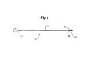
- FIG. 1depicts a catheter assembly in accordance with the present invention.
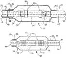
- FIG. 2depicts an embodiment of an inventive catheter tip.
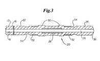
- FIG. 3shows a cross-sectional side view of an embodiment of an inventive catheter tip.
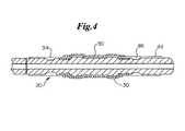
- FIG. 4shows a cross-sectional side view of an embodiment of an inventive catheter tip and a stent in an unexpanded configuration.
- FIG. 5shows a cross-sectional side view of an embodiment of an inventive catheter tip and a stent in an expanded configuration.
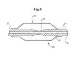
- FIG. 6depicts a cross-sectional side view of an embodiment of an inventive catheter tip.
- FIG. 7depicts a cross-sectional side view of an embodiment of an inventive catheter tip.
- FIG. 8depicts a cross-sectional side view of an embodiment of an inventive catheter tip.
- FIG. 9depicts a cross-sectional side view of an embodiment of an inventive catheter tip.
- FIG. 10depicts a cross-sectional side view of an embodiment of an inventive catheter tip.
- FIG. 11depicts a side view of an embodiment of an inventive catheter tip.
- FIG. 12depicts a front view of an embodiment of an inventive catheter tip.
- FIG. 13depicts a side view of an embodiment of an inventive catheter tip.
- a stent delivery catheter 10having a catheter shaft 12 and a catheter tip 20 .
- the catheter shaft 12has a proximal end 14 and a distal end 16 , and further comprises a lumen 18 extending therethrough (see FIG. 2 ).
- the catheter tip 20is coupled to the catheter shaft distal end 16 at a coupling 38 .
- the catheter shaft 12 and catheter tipmay be made from any suitable material, such as polyesters and copolymers thereof such as those sold including polyalkylene terephthalates such as polyethylene terephthalate (PET) and polybutylene terephthalate (PBT) available under the tradename of EKTAR® available from Eastman Chemical Co.
- PETpolyethylene terephthalate
- PBTpolybutylene terephthalate
- polycyclohexylene terephthalatePCT
- poly(trimethylene terephthalate)PTT
- PCTGpoly(cyclohexanedimethanol-co-ethylene terephthalate)
- PETpoly(trimethylene terephthalate)
- PETGpoly(cyclohexanedimethanol-co-ethylene terephthalate) copolyesters available under the tradename of EASTAR® available from Eastman Chemical Co.
- PCTAavailable under the tradename of DURASTAR® available from Eastman Chemical Co.
- poly(ethylene naphthalate) (PEN) polyesteravailable from DuPont in Wilmington, DE under the tradename of TEONEX®; and so forth
- polyester elastomersPEELs
- polyamidessuch as amorphous nylon and nylon 12 such as those available from Elf Atochem under the tradename of CRISTAMID® and copolymers thereof such as GRILAMID® TR-55-LX nylon 12 polyether-block-amide available from EMS-American
- the catheter tip 20may be made from any suitable material, such as described above, and is desirably more flexible than the catheter shaft 12 .
- the catheter tip 20is desirably made from a soft material, such as Pebax 40D, Pebax 55D or silicone.
- the catheter tip 20may be attached to the catheter shaft 12 using any suitable process, such as gluing, heat bonding, RF welding or laser welding.
- any suitable processsuch as gluing, heat bonding, RF welding or laser welding.
- the catheter shaft 12 and catheter tip 20are desirably made from materials having similar melting temperatures.
- catheter tips 20desirably comprise an elongate tubular body having a proximal end 22 , a distal end 24 , a lumen 26 extending therethrough, a distal shaft portion 42 and a main shaft portion.
- the main shaft portionmay be defined as the portion of the catheter tip 20 not defined as the distal shaft portion 42 .
- the main shaft portioncan have a greater length then the distal shaft portion 42 .
- the catheter tips 20may optionally include one or more hub portions 30 , one or more markers or marker portions 32 , one or more recessed portions 34 , one or more stiffeners or reinforcements 28 and a radiused tip 36 .
- a balloon 44generally includes a proximal waist portion 54 and a distal waist portion 56 .
- a balloon 44can be coupled at its proximal waist portion 54 to an outer catheter shaft 40 , and at its distal waist portion 56 to the catheter tip 20 distal shaft portion 42 .
- the length of the balloon 44may be substantially coextensive with the catheter tip 20 main shaft portion.
- the catheter tip 20may be coupled to the catheter shaft distal end 16 near the balloon proximal waist portion 54 .
- the coupling 38may be proximal to the balloon proximal waist portion 54 .
- the coupling 38may be distal to the balloon proximal waist portion 54 .
- the catheter tip 20may include a medical device mounting region, such as for mounting a stent, and the mounting region can be distal to the coupling between the catheter shaft 12 and catheter tip 20 .
- catheter tips 20are formed using a molding process or an extrusion process. Both a molding process and an extrusion process allow the catheter tip 20 to be precisely formed having sections of varying diameter.
- hub portions 30 , recessed portions 34 and a radiused tip 36may be integrally formed during tip manufacture, without separate installation or grinding steps.
- markers 32 or stiffeners 28may be inserted into the mold prior to material injection.
- markers 32 and stiffeners 28may be insert molded upon the catheter tip 20 .
- stiffeners 28may be used to increase rigidity of the catheter tip, as depicted in FIG. 3 .
- a stiffener 28is desirably insert molded into the catheter tip 20 , and may comprise a strip of material, a cylinder of material, or the like. In one embodiment, the stiffener 28 may comprise a cylindrical coil of wire or a spring. A stiffener 28 may work to resist kinking of the catheter tip 20 .
- Markers 32may comprise radiopaque markers, MRI markers, and the like. Markers 32 may be of any suitable shape and desirably comprise circumferential bands, as depicted in FIGS. 2 and 3 . In one embodiment, markers 32 may be inserted into the mold during manufacture of the catheter tip 20 . As such, material used to form the catheter tip 20 forms around the marker 32 during the molding process, thereby securing the marker 32 in place without the use of adhesive or a separate installation step. Insert molding additionally allows the markers 32 to have a lower profile than is typically achieved with conventional assembly. Desirably, the outer surface of any markers 32 may be flush with the outer surface of the catheter tip 20 , or even recessed beneath the surface.
- the markers 32may be raised, or otherwise protrude above the outer surface of the catheter tip 20 .
- the markers 32may even function as hub portions 30 .
- the catheter tip 20may be used in a stent delivery system, and may be used to deliver inflation expandable, self-expanding or hybrid stents.
- Inflation expandable stentsare generally crimped about the delivery catheter and the deflated balloon 44 . After being maneuvered to the deployment site, the inflation expandable stent is expanded to the vessel diameter by fluid inflation of the balloon 44 .
- a self-expanding stentis generally formed from a shape-memory material, such as Nitinol, and held in a reduced diameter about a catheter with a sheath. Upon removal of the sheath, a self-expanding stent will deploy to a deployment diameter.
- the delivery system for a self-expanding stentmay or may not use a balloon 44 .
- Markers 32are desirably located at a position corresponding to eventual placement of end portions of a stent that may eventually be installed about the catheter tip 20 .
- the stent end portionsmay be adjacent to or otherwise aligned with the markers 32 .
- Radiopaque markers 32may be any suitable material, including barium, bismuth, tungsten, gold, titanium, iridium, platinum, palladium, silver, rhenium, alloys of these materials, and others, such as disclosed in U.S. Pat. No. 6,315,790, incorporated herein by reference.
- MRI markers 32may be any suitable material, and desirably a ferro-magnetic, superparamagnetic or paramagnetic material in such a quantity that the magnetic field surrounding the catheter tip 20 is disturbed enough to visualize the marker 32 on a magnetic resonance imaging system, such as gadolinium, iron or manganese containing alloys. Further, the markers 32 may be positioned with a portion raised above the surface of the catheter tip 20 , and may also be used as a hub to prevent translocation of an unexpanded stent.
- a molding processis also beneficial in that placement of various features of the catheter tip 20 is consistent for all tips 20 manufactured from a given mold. Hub portions 30 , markers 32 , stiffeners 28 and recessed portions 34 may be placed precisely and consistently in relation to the ends of the catheter tip 20 , as well as in relation to each other.
- hub portions 30may help to prevent a stent 50 from translocating proximally or distally when the stent 50 is in an unexpanded state, such as crimped to the catheter tip 20 .
- Recessed portions 34may be located strategically to allow a catheter assembly to have a lower profile in desired locations.
- An expansion balloon 44may include conical portions 46 where the diameter of the balloon 44 increases or decreases rapidly, as best shown in FIG. 5 with the balloon 44 in an expanded configuration. When the balloon 44 is installed on a conventional catheter in an uninflated configuration, the conical portions 46 may bunch undesirably to create a larger outer diameter.
- Recessed portions 34 in the catheter tip 20may be located to act as a storage recess for portions of the balloon, for example the conical portions 46 , thereby allowing the catheter tip assembly to have a lower profile in those sections.
- recessed portions 34allow for greater flexibility of the catheter tip 20 in bending about the longitudinal axis. This aids in advancement of the catheter through a tortuous anatomy en route to a stent deployment site. However, if a greater flexibility is not desired in the regions of recessed portions 34 , stiffeners 28 may be used appropriately for added rigidity.
- catheter tips 20may include various combinations of the features described herein.
- an embodimentmay include a single hub portion 30 , and have no recessed portions 34 and no markers 32 .
- Another embodimentmay include a single marker 32 and a radiused tip 36 .
- a catheter tip 20having a large central recessed portion 34 .
- the large recessed portion 34may act as a securement recess to help prevent translocation of an unexpanded stent.
- the recessed portion 34also allows for greater flexibility of the catheter tip 20 in bending about the longitudinal axis.
- FIG. 7A further embodiment, having multiple recessed portions 34 is depicted in FIG. 7 .
- the catheter tip 20has an undulating or serpentine surface along a portion of its length. Multiple recessed portions 34 can be more effective at securing an unexpanded stent than a single, larger recessed portion. Multiple recessed portions 34 also allow an increase in longitudinal flexibility across a greater length of the catheter tip 20 . Adjacent recessed portions 34 may have varying outer diameters. Further, portions of the catheter tip 20 between adjacent recessed portions 34 may function as securement hubs 30 , and may have a greater outer diameter than the tip proximal end 22 or the tip distal end 24 .
- FIG. 8shows an embodiment wherein the catheter tip 20 includes a large recessed portion 34 b .
- a stent 50may be mounted upon the tip 20 such that the outer surface of the stent 50 may be flush with the tip 20 outer diameter, or even recessed beneath the tip 20 outer diameter.
- Markers 28are further recessed within the large recessed portion 34 b , and thus may be located proximal to ends of the stent 50 .
- portions of the catheter tip 20 that are directly adjacent to the ends of the stent 50can act as securement hubs 30 and prevent the stent 50 from translocating.
- FIG. 9depicts another embodiment of a catheter tip 20 , wherein securement hubs 30 are located outwardly from the markers 28 .
- a stent 50may be mounted upon the tip 20 such that the outer surface of the stent 50 may be flush with the securement hubs 30 , or nested between the securement hubs 30 .
- Markers 28may be located proximal to the ends of the stent 50 .
- the catheter tip 20may be formed having various regions, each region having properties that may be different from the other regions of the tip 20 .
- a regionmay comprise a marker region, and thus have radiopaque or magnetic properties.
- a regionmay also be more or less flexible than an adjacent region.
- Various regionsmay have differing melting points, and a catheter tip 20 may be molded utilizing a multiple step process wherein a first material composition is injected into a first mold to form a portion of the tip, which can then be inserted into a second mold, and a second material composition may be injected. Properties of regions may be adjusted via the use of various materials in forming the regions of the catheter tip 20 .
- a catheter tip 20 manufactured to have marker regionsmay have radiopaque material entrained with the polymer material for that region, and would not require a separate radiopaque marker 32 in order to be viewable under fluoroscopy.
- FIG. 10shows a catheter tip 20 comprising a first region 60 , one or more second regions 62 , and one or more marker regions 64 .
- the first region 60may comprise a soft distal region.
- a first region 60may be made from a first matrix material composition.
- a second region 62may have reduced flexibility as compared to a first region 60 .
- a second regionmay be made from a second matrix material composition.
- a first matrix material compositionmay include portions of materials that are also present in a second matrix material composition.
- a reduced flexibilitymay be accomplished, for example, by including stiffening fibers within the polymer used to form the second region 62 .
- Stiffening fiberscan include carbon fibers, polypropylene fibers, polyolefin fibers, or any other material to accomplish an appropriate reduction in flexibility.
- a marker region 64can be visible under fluoroscopy or MRI.
- a radiopaque regionmay be formed by including radiopaque material in the region. For example, up to 90% bismuthoxide by weight may be loaded into the polymer matrix. Other materials include ceramic materials such as tungsten carbide, tungsten boride, and the like, and metals such as platinum, tantalum, iridium, tungsten, rhenium gold and alloys of such metals.
- An MRI regionmay be similarly formed using any appropriate material, such as terbiumoxide, gadoliniumoxide and dysrosiumoxide.
- Regions of the catheter tip 20may be formed using any suitable methods, such as molding or extrusion.
- each regionmay be injection molded, and each region may be formed with an individual injector.
- Methods of forming an extrusion having alternating materialsare disclosed in U.S. Pat. No. 5,622,665, incorporated herein by reference.
- Catheter tips 20 having regions of varying stiffness and marker regionsmay also include all of the features of inventive catheter tips 20 described herein, such as recessed portions 34 , securement hubs 30 , markers 32 and stiffeners 28 .
- marker regions 64may include a raised portion and function as a securement hub 30 .
- the entire stent mounting regionmay comprise a marker region 64 .
- a regionmay comprise both a marker region 64 and a region of reduced flexibility.
- portions of the catheter tip 20may have various cross-sectional shapes.
- FIGS. 11 and 12depict a catheter tip 20 having a triangular cross-sectional portion.
- a varying cross-sectional shape portioncan be formed wherein the cross-sectional shape has a reduced cross-sectional area when compared to the catheter shaft 12 . Areas where a cross-sectional shape does not extend to the catheter shaft 12 diameter may be described as reduced profile zones. In other embodiments, cross-sectional area of a shaped portion may be greater than that of the catheter shaft 12 .
- a shaped cross-sectional portionmay be better suited to receive an unexpanded balloon than a circular cross section.
- the folds of an unexpanded balloonmay be located in a reduced profile zone, and as such, the balloon may have a lower cross-sectional profile than that of the catheter shaft 12 .
- a shaped cross-sectional portionmay be of any shape desired.
- Various embodimentsinclude a square, pentagon, hexagon, and the like. The number of sides of the shape may increase until the shape becomes substantially circular.
- a catheter tip 20 having a shaped cross-sectional portionmay also have circular portions which are of the same dimensions as the catheter shaft 12 .
- the catheter tip 20 proximal end 22is of the same shape as the catheter shaft 12 .
- Catheter tips 20 that include a shaped cross-sectional portionmay also include all of the features of inventive catheter tips 20 described herein, such as regions of varying stiffness and marker regions, recessed portions 34 , securement hubs 30 , markers 32 and stiffeners 28 .
- a catheter tip 20may be separate from a catheter shaft 12 .
- a separate catheter tip 20can later be coupled to a catheter shaft 12 .
- FIG. 13shows a separate catheter tip 20 .
- a catheter tip 20may have a first free end 66 and a second free end 68 .
- the catheter tip 20may have a longitudinal axis, a length along the longitudinal axis, a width orthogonal to the length, and a height orthogonal to both the length and the width.
- the catheter tip 20 lengthcan encompass a range to be suitable for delivery of a range of medical devices.
- the catheter tip 20may have a length of 4 millimeters in some embodiments, and a length of 70 millimeters in some other embodiments.
- the length of the catheter tip 20can also vary in relation to the width or diameter.
- the lengthcan be 4 times the width or diameter in some embodiments, and 70 times the width or diameter in some other embodiments. Many other specific lengths may be utilized according to the particular application.
- the catheter tip 20can include a balloon 44 .
- the main shaft portion of the catheter tip 20can be substantially coextensive with the balloon 44 .
- any dependent claim which followsshould be taken as alternatively written in a multiple dependent form from all prior claims which possess all antecedents referenced in such dependent claim if such multiple dependent format is an accepted format within the jurisdiction (e.g. each claim depending directly from claim 1 should be alternatively taken as depending from all previous claims).
- each claim depending directly from claim 1should be alternatively taken as depending from all previous claims.
- the following dependent claimsshould each be also taken as alternatively written in each singly dependent claim format which creates a dependency from a prior antecedent-possessing claim other than the specific claim listed in such dependent claim below.
Landscapes
- Health & Medical Sciences (AREA)
- Life Sciences & Earth Sciences (AREA)
- Biomedical Technology (AREA)
- Heart & Thoracic Surgery (AREA)
- Engineering & Computer Science (AREA)
- Veterinary Medicine (AREA)
- Animal Behavior & Ethology (AREA)
- Public Health (AREA)
- General Health & Medical Sciences (AREA)
- Biophysics (AREA)
- Hematology (AREA)
- Pulmonology (AREA)
- Anesthesiology (AREA)
- Child & Adolescent Psychology (AREA)
- Cardiology (AREA)
- Oral & Maxillofacial Surgery (AREA)
- Transplantation (AREA)
- Vascular Medicine (AREA)
- Media Introduction/Drainage Providing Device (AREA)
Abstract
Description
Claims (29)
Priority Applications (4)
| Application Number | Priority Date | Filing Date | Title |
|---|---|---|---|
| US10/767,675US7972350B2 (en) | 2004-01-29 | 2004-01-29 | Catheter tip |
| PCT/US2004/038299WO2005075014A1 (en) | 2004-01-29 | 2004-11-17 | Catheter tip |
| EP04811126.4AEP1708775B2 (en) | 2004-01-29 | 2004-11-17 | Catheter tip |
| CA2537951ACA2537951C (en) | 2004-01-29 | 2004-11-17 | Catheter tip |
Applications Claiming Priority (1)
| Application Number | Priority Date | Filing Date | Title |
|---|---|---|---|
| US10/767,675US7972350B2 (en) | 2004-01-29 | 2004-01-29 | Catheter tip |
Publications (2)
| Publication Number | Publication Date |
|---|---|
| US20050171591A1 US20050171591A1 (en) | 2005-08-04 |
| US7972350B2true US7972350B2 (en) | 2011-07-05 |
Family
ID=34807715
Family Applications (1)
| Application Number | Title | Priority Date | Filing Date |
|---|---|---|---|
| US10/767,675Active2025-10-29US7972350B2 (en) | 2004-01-29 | 2004-01-29 | Catheter tip |
Country Status (4)
| Country | Link |
|---|---|
| US (1) | US7972350B2 (en) |
| EP (1) | EP1708775B2 (en) |
| CA (1) | CA2537951C (en) |
| WO (1) | WO2005075014A1 (en) |
Cited By (3)
| Publication number | Priority date | Publication date | Assignee | Title |
|---|---|---|---|---|
| US20080234584A1 (en)* | 1999-03-10 | 2008-09-25 | Cordatec Nv | Method and System for Ultrasonic Imaging of an Organ in a Patient's Body Through a Part of the Patient's Respiratory Tract |
| US9526644B2 (en) | 2006-11-22 | 2016-12-27 | Inspiremd, Ltd. | Optimized drug-eluting stent assembly methods |
| US20210338424A1 (en)* | 2018-07-24 | 2021-11-04 | Innovations For Heart And Vessels Sp. Z O.O. | Delivery system for implants used in structural heart diseases by a minimally invasive method |
Families Citing this family (22)
| Publication number | Priority date | Publication date | Assignee | Title |
|---|---|---|---|---|
| US8961586B2 (en) | 2005-05-24 | 2015-02-24 | Inspiremd Ltd. | Bifurcated stent assemblies |
| US8043323B2 (en) | 2006-10-18 | 2011-10-25 | Inspiremd Ltd. | In vivo filter assembly |
| CA2609687C (en) | 2005-05-24 | 2014-04-22 | Inspire M.D Ltd. | Stent apparatuses for treatment via body lumens and methods of use |
| US20100030250A1 (en)* | 2005-08-19 | 2010-02-04 | Abbott Laboratories Vascular Enterprises Limited | Catheter, in particular ptca catheter |
| US7819802B2 (en)* | 2005-11-22 | 2010-10-26 | General Electric Company | Catheter tip |
| DE102005059261B4 (en)* | 2005-12-12 | 2013-09-05 | Siemens Aktiengesellschaft | Catheter device for the treatment of a partial and / or complete vascular occlusion and X-ray device |
| CH705338B1 (en)* | 2006-06-07 | 2013-02-15 | Schwager Medica Ag | Catheter tip. |
| GB0616411D0 (en)* | 2006-08-18 | 2006-09-27 | Renishaw Plc | Neurosurgical instruments |
| WO2008047369A2 (en) | 2006-10-18 | 2008-04-24 | Inspiremd Ltd. | Knitted stent jackets |
| US20090093794A1 (en)* | 2007-10-03 | 2009-04-09 | Tyco Healthcare Group Lp | Bolus tube assembly |
| US20100174243A1 (en)* | 2009-01-05 | 2010-07-08 | Warsaw Orthopedic, Inc. | Apparatus for Delivery of Therapeutic Material to an Intervertebral Disc and Method of Use |
| US20090192448A1 (en)* | 2009-01-28 | 2009-07-30 | Talamonti Anthony R | Oral gastric lavage apparatus |
| US20120238806A1 (en)* | 2009-08-24 | 2012-09-20 | Quali-Med Gmbh | Implantation system with handle and catheter and method of use thereof |
| US9233015B2 (en) | 2012-06-15 | 2016-01-12 | Trivascular, Inc. | Endovascular delivery system with an improved radiopaque marker scheme |
| US9757536B2 (en)* | 2012-07-17 | 2017-09-12 | Novartis Ag | Soft tip cannula |
| JP7044552B2 (en) | 2015-01-20 | 2022-03-30 | キューアペル メディカル, エルエルシー | Tubular structure with variable support |
| CN110022925B (en) | 2016-07-27 | 2024-05-28 | 乔佩尔医疗公司 | Tubular structure with variable support |
| DE102018121206A1 (en)* | 2018-08-30 | 2020-03-05 | Karl Storz Se & Co. Kg | Endoscopic shaft with a layered structure and method for producing such |
| WO2020060859A1 (en)* | 2018-09-18 | 2020-03-26 | Boston Scientific Scimed, Inc. | Ribbed dilator tip |
| WO2021084591A1 (en)* | 2019-10-28 | 2021-05-06 | オリンパス株式会社 | Endoscope |
| AU2021367849B2 (en)* | 2020-10-29 | 2024-08-22 | Coopersurgical, Inc. | Distal tips of surgical tools and related methods |
| CN117500555A (en)* | 2021-06-17 | 2024-02-02 | 科洛普拉斯特公司 | Method for forming a catheter tip |
Citations (69)
| Publication number | Priority date | Publication date | Assignee | Title |
|---|---|---|---|---|
| US3832253A (en) | 1973-03-21 | 1974-08-27 | Baxter Laboratories Inc | Method of making an inflatable balloon catheter |
| US3865666A (en) | 1973-05-08 | 1975-02-11 | Int Paper Co | Method of making a catheter |
| US3884242A (en) | 1971-03-29 | 1975-05-20 | Mpc Kurgisil | Catheter assembly |
| US3959429A (en) | 1975-02-03 | 1976-05-25 | International Paper Company | Method of making a retention catheter and molding a tip thereon |
| US4157094A (en) | 1977-09-01 | 1979-06-05 | The Kendall Company | Catheter with improved balloon and tip assembly |
| US4210478A (en) | 1973-05-08 | 1980-07-01 | International Paper Company | Method of making a catheter |
| US4276874A (en)* | 1978-11-15 | 1981-07-07 | Datascope Corp. | Elongatable balloon catheter |
| US4284459A (en) | 1978-07-03 | 1981-08-18 | The Kendall Company | Method for making a molded catheter |
| US4531943A (en) | 1983-08-08 | 1985-07-30 | Angiomedics Corporation | Catheter with soft deformable tip |
| US4597755A (en)* | 1984-05-30 | 1986-07-01 | Advanced Cardiovascular Systems, Inc. | Large bore catheter having flexible tip construction |
| US4665925A (en)* | 1985-09-13 | 1987-05-19 | Pfizer Hospital Products Group, Inc. | Doppler catheter |
| US4739769A (en)* | 1985-02-07 | 1988-04-26 | Board Of Reagents Of The University Of Michigan | Tissue pressure measurement transducer system |
| US4842590A (en) | 1983-12-14 | 1989-06-27 | Terumo Kabushiki Kaisha | Catheter and method for making |
| US5250069A (en)* | 1987-02-27 | 1993-10-05 | Terumo Kabushiki Kaisha | Catheter equipped with expansible member and production method thereof |
| US5254091A (en)* | 1991-01-08 | 1993-10-19 | Applied Medical Resources Corporation | Low profile balloon catheter and method for making same |
| US5318032A (en) | 1992-02-05 | 1994-06-07 | Devices For Vascular Intervention | Guiding catheter having soft tip |
| EP0611582A2 (en) | 1993-01-19 | 1994-08-24 | Datascope Investment Corp. | Single-lumen over-the-wire IAB catheter |
| US5509910A (en) | 1994-05-02 | 1996-04-23 | Medtronic, Inc. | Method of soft tip attachment for thin walled catheters |
| US5514236A (en) | 1992-09-18 | 1996-05-07 | Cordis Corporation | Method of making fiber-reinforced catheter introducer |
| US5549552A (en) | 1995-03-02 | 1996-08-27 | Scimed Life Systems, Inc. | Balloon dilation catheter with improved pushability, trackability and crossability |
| US5622665A (en) | 1994-04-20 | 1997-04-22 | Wang; James C. | Method for making tubing |
| US5645528A (en) | 1995-06-06 | 1997-07-08 | Urologix, Inc. | Unitary tip and balloon for transurethral catheter |
| US5653691A (en) | 1996-04-25 | 1997-08-05 | Rupp; Garry Eugene | Thickened inner lumen for uniform stent expansion and method of making |
| US5728063A (en) | 1994-11-23 | 1998-03-17 | Micro International Systems, Inc. | High torque balloon catheter |
| US5728065A (en)* | 1996-06-21 | 1998-03-17 | Medtronic, Inc. | Self-venting elastomeric balloon catheter |
| US5762637A (en) | 1996-08-27 | 1998-06-09 | Scimed Life Systems, Inc. | Insert molded catheter tip |
| US5766203A (en)* | 1995-07-20 | 1998-06-16 | Intelliwire, Inc. | Sheath with expandable distal extremity and balloon catheters and stents for use therewith and method |
| US5788707A (en) | 1995-06-07 | 1998-08-04 | Scimed Life Systems, Inc. | Pull back sleeve system with compression resistant inner shaft |
| US5830401A (en) | 1992-07-10 | 1998-11-03 | Sherwood Medical Company | Method of manufacturing a catheter/hub strain relief |
| EP0884060A2 (en) | 1997-05-22 | 1998-12-16 | Smiths Industries Public Limited Company | Cuffed tube assemblies |
| US5906606A (en)* | 1995-12-04 | 1999-05-25 | Target Therapuetics, Inc. | Braided body balloon catheter |
| US5921958A (en)* | 1992-02-10 | 1999-07-13 | Scimed Life Systems, Inc. | Intravascular catheter with distal tip guide wire lumen |
| US5944726A (en) | 1996-08-23 | 1999-08-31 | Scimed Life Systems, Inc. | Stent delivery system having stent securement means |
| WO1999044666A2 (en) | 1998-03-04 | 1999-09-10 | Scimed Life Systems, Inc. | Catheter tip designs and methods for improved stent crossing |
| US5951585A (en)* | 1995-05-23 | 1999-09-14 | Boston Scientific Corporation | Vena cava delivery system |
| US5951569A (en) | 1997-04-29 | 1999-09-14 | Medtronic, Inc. | Stent delivery system |
| WO1999048548A1 (en) | 1998-03-23 | 1999-09-30 | Medtronic, Inc. | Catheter having extruded radiopaque stripes embedded in soft tip and method of fabrication |
| US5968012A (en) | 1997-08-22 | 1999-10-19 | Scimed Lifesystems, Inc. | Balloon catheter with adjustable shaft |
| US6007543A (en) | 1996-08-23 | 1999-12-28 | Scimed Life Systems, Inc. | Stent delivery system with stent securement means |
| US6048485A (en) | 1996-12-13 | 2000-04-11 | Johnson & Johnson Medical, Inc. | Thermal gradient beveling of catheters |
| US6074374A (en)* | 1998-07-31 | 2000-06-13 | Angiodynamics, Inc. | Catheter with lumen occluding means |
| US6113579A (en) | 1998-03-04 | 2000-09-05 | Scimed Life Systems, Inc. | Catheter tip designs and methods for improved stent crossing |
| US6149996A (en) | 1998-01-15 | 2000-11-21 | Schneider (Usa) Inc. | Molded tip and tubing and method of making same |
| US6162229A (en)* | 1992-09-30 | 2000-12-19 | Staar Surgical Company, Inc. | Deformable intraocular lens injecting apparatus with deformable tip plunger |
| US6168621B1 (en) | 1998-05-29 | 2001-01-02 | Scimed Life Systems, Inc. | Balloon expandable stent with a self-expanding portion |
| US6203558B1 (en) | 1996-08-23 | 2001-03-20 | Scimed Life Systems, Inc. | Stent delivery system having stent securement apparatus |
| US6315790B1 (en) | 1999-06-07 | 2001-11-13 | Scimed Life Systems, Inc. | Radiopaque marker bands |
| WO2001089620A2 (en) | 2000-05-22 | 2001-11-29 | Jomed Gmbh | Soft-tip catheter for implanting stents |
| US20010051784A1 (en)* | 1996-09-05 | 2001-12-13 | Axel Brisken | Balloon catheters having ultrasonically driven interface surfaces and methods for their use |
| US6332874B1 (en) | 1998-08-28 | 2001-12-25 | C.R. Bard, Inc. | Coupling and stabilization system for proximal end of catheter |
| US6348065B1 (en) | 1995-03-01 | 2002-02-19 | Scimed Life Systems, Inc. | Longitudinally flexible expandable stent |
| US6350277B1 (en) | 1999-01-15 | 2002-02-26 | Scimed Life Systems, Inc. | Stents with temporary retaining bands |
| US20020038103A1 (en) | 1999-06-30 | 2002-03-28 | Advanced Cardiovascular Systems, Inc. | Catheter with enhanced flexibility |
| US6374476B1 (en) | 1999-03-03 | 2002-04-23 | Codris Webster, Inc. | Method for making a catheter tip section |
| US20020049424A1 (en) | 2000-10-04 | 2002-04-25 | Biocompatibles Limited | Catheter tip |
| US20020055770A1 (en) | 1998-11-20 | 2002-05-09 | Doran Burns P. | Flexible and expandable stent |
| US6395008B1 (en)* | 1996-08-23 | 2002-05-28 | Scimed Life Systems, Inc. | Stent delivery device using stent cups and mounting collars |
| US6398709B1 (en)* | 1999-10-19 | 2002-06-04 | Scimed Life Systems, Inc. | Elongated member for intravascular delivery of radiation |
| US6447540B1 (en) | 1996-11-15 | 2002-09-10 | Cook Incorporated | Stent deployment device including splittable sleeve containing the stent |
| US6447522B2 (en)* | 1998-09-30 | 2002-09-10 | C. R. Bard, Inc. | Implant delivery system |
| US6458138B1 (en) | 1995-03-24 | 2002-10-01 | Scimed Life Systems, Inc. | Selective coating of a balloon catheter with lubricious material for stent deployment |
| US6500285B2 (en) | 1999-08-23 | 2002-12-31 | Scimed Life Systems, Inc. | Method of making a catheter having interlocking ribbed bond regions |
| US6508806B1 (en) | 2000-12-13 | 2003-01-21 | Advanced Cardiovascular Systems, Inc. | Catheter with multi-layer wire reinforced wall construction |
| US6530947B1 (en) | 1993-10-22 | 2003-03-11 | Scimed Life Systems, Inc | Stent delivery apparatus and method |
| US20030055449A1 (en) | 2001-09-19 | 2003-03-20 | Advanced Cardiovascular Systems, Inc. | MRI visible catheter balloon |
| US6544218B1 (en) | 2000-07-26 | 2003-04-08 | Advanced Cardiovascular Systems, Inc. | Catheter with biased shaft |
| US20030069522A1 (en)* | 1995-12-07 | 2003-04-10 | Jacobsen Stephen J. | Slotted medical device |
| US6575959B1 (en) | 1999-12-27 | 2003-06-10 | Scimed Life Systems, Inc. | Catheter incorporating an insert molded hub and method of manufacturing |
| US6746424B2 (en) | 1999-12-11 | 2004-06-08 | Advanced Cardiovascular Systems, Inc. | Shaftless balloon |
Family Cites Families (3)
| Publication number | Priority date | Publication date | Assignee | Title |
|---|---|---|---|---|
| US55770A (en)* | 1866-06-19 | Improved paddle-wheel | ||
| US4844092A (en)† | 1988-03-28 | 1989-07-04 | Schneider-Shiley (Usa) Inc. | Catheter Y-connector with guidewire locking means |
| JP3782238B2 (en)* | 1997-08-05 | 2006-06-07 | 富士写真フイルム株式会社 | Silver halide color photographic light-sensitive material and color image forming method |
- 2004
- 2004-01-29USUS10/767,675patent/US7972350B2/enactiveActive
- 2004-11-17EPEP04811126.4Apatent/EP1708775B2/ennot_activeExpired - Lifetime
- 2004-11-17WOPCT/US2004/038299patent/WO2005075014A1/ennot_activeApplication Discontinuation
- 2004-11-17CACA2537951Apatent/CA2537951C/ennot_activeExpired - Fee Related
Patent Citations (69)
| Publication number | Priority date | Publication date | Assignee | Title |
|---|---|---|---|---|
| US3884242A (en) | 1971-03-29 | 1975-05-20 | Mpc Kurgisil | Catheter assembly |
| US3832253A (en) | 1973-03-21 | 1974-08-27 | Baxter Laboratories Inc | Method of making an inflatable balloon catheter |
| US3865666A (en) | 1973-05-08 | 1975-02-11 | Int Paper Co | Method of making a catheter |
| US4210478A (en) | 1973-05-08 | 1980-07-01 | International Paper Company | Method of making a catheter |
| US3959429A (en) | 1975-02-03 | 1976-05-25 | International Paper Company | Method of making a retention catheter and molding a tip thereon |
| US4157094A (en) | 1977-09-01 | 1979-06-05 | The Kendall Company | Catheter with improved balloon and tip assembly |
| US4284459A (en) | 1978-07-03 | 1981-08-18 | The Kendall Company | Method for making a molded catheter |
| US4276874A (en)* | 1978-11-15 | 1981-07-07 | Datascope Corp. | Elongatable balloon catheter |
| US4531943A (en) | 1983-08-08 | 1985-07-30 | Angiomedics Corporation | Catheter with soft deformable tip |
| US4842590A (en) | 1983-12-14 | 1989-06-27 | Terumo Kabushiki Kaisha | Catheter and method for making |
| US4597755A (en)* | 1984-05-30 | 1986-07-01 | Advanced Cardiovascular Systems, Inc. | Large bore catheter having flexible tip construction |
| US4739769A (en)* | 1985-02-07 | 1988-04-26 | Board Of Reagents Of The University Of Michigan | Tissue pressure measurement transducer system |
| US4665925A (en)* | 1985-09-13 | 1987-05-19 | Pfizer Hospital Products Group, Inc. | Doppler catheter |
| US5250069A (en)* | 1987-02-27 | 1993-10-05 | Terumo Kabushiki Kaisha | Catheter equipped with expansible member and production method thereof |
| US5254091A (en)* | 1991-01-08 | 1993-10-19 | Applied Medical Resources Corporation | Low profile balloon catheter and method for making same |
| US5318032A (en) | 1992-02-05 | 1994-06-07 | Devices For Vascular Intervention | Guiding catheter having soft tip |
| US5921958A (en)* | 1992-02-10 | 1999-07-13 | Scimed Life Systems, Inc. | Intravascular catheter with distal tip guide wire lumen |
| US5830401A (en) | 1992-07-10 | 1998-11-03 | Sherwood Medical Company | Method of manufacturing a catheter/hub strain relief |
| US5514236A (en) | 1992-09-18 | 1996-05-07 | Cordis Corporation | Method of making fiber-reinforced catheter introducer |
| US6162229A (en)* | 1992-09-30 | 2000-12-19 | Staar Surgical Company, Inc. | Deformable intraocular lens injecting apparatus with deformable tip plunger |
| EP0611582A2 (en) | 1993-01-19 | 1994-08-24 | Datascope Investment Corp. | Single-lumen over-the-wire IAB catheter |
| US6530947B1 (en) | 1993-10-22 | 2003-03-11 | Scimed Life Systems, Inc | Stent delivery apparatus and method |
| US5622665A (en) | 1994-04-20 | 1997-04-22 | Wang; James C. | Method for making tubing |
| US5509910A (en) | 1994-05-02 | 1996-04-23 | Medtronic, Inc. | Method of soft tip attachment for thin walled catheters |
| US5728063A (en) | 1994-11-23 | 1998-03-17 | Micro International Systems, Inc. | High torque balloon catheter |
| US6348065B1 (en) | 1995-03-01 | 2002-02-19 | Scimed Life Systems, Inc. | Longitudinally flexible expandable stent |
| US5549552A (en) | 1995-03-02 | 1996-08-27 | Scimed Life Systems, Inc. | Balloon dilation catheter with improved pushability, trackability and crossability |
| US6458138B1 (en) | 1995-03-24 | 2002-10-01 | Scimed Life Systems, Inc. | Selective coating of a balloon catheter with lubricious material for stent deployment |
| US5951585A (en)* | 1995-05-23 | 1999-09-14 | Boston Scientific Corporation | Vena cava delivery system |
| US5645528A (en) | 1995-06-06 | 1997-07-08 | Urologix, Inc. | Unitary tip and balloon for transurethral catheter |
| US5788707A (en) | 1995-06-07 | 1998-08-04 | Scimed Life Systems, Inc. | Pull back sleeve system with compression resistant inner shaft |
| US5766203A (en)* | 1995-07-20 | 1998-06-16 | Intelliwire, Inc. | Sheath with expandable distal extremity and balloon catheters and stents for use therewith and method |
| US5906606A (en)* | 1995-12-04 | 1999-05-25 | Target Therapuetics, Inc. | Braided body balloon catheter |
| US20030069522A1 (en)* | 1995-12-07 | 2003-04-10 | Jacobsen Stephen J. | Slotted medical device |
| US5653691A (en) | 1996-04-25 | 1997-08-05 | Rupp; Garry Eugene | Thickened inner lumen for uniform stent expansion and method of making |
| US5728065A (en)* | 1996-06-21 | 1998-03-17 | Medtronic, Inc. | Self-venting elastomeric balloon catheter |
| US5944726A (en) | 1996-08-23 | 1999-08-31 | Scimed Life Systems, Inc. | Stent delivery system having stent securement means |
| US6007543A (en) | 1996-08-23 | 1999-12-28 | Scimed Life Systems, Inc. | Stent delivery system with stent securement means |
| US6395008B1 (en)* | 1996-08-23 | 2002-05-28 | Scimed Life Systems, Inc. | Stent delivery device using stent cups and mounting collars |
| US6203558B1 (en) | 1996-08-23 | 2001-03-20 | Scimed Life Systems, Inc. | Stent delivery system having stent securement apparatus |
| US5762637A (en) | 1996-08-27 | 1998-06-09 | Scimed Life Systems, Inc. | Insert molded catheter tip |
| US20010051784A1 (en)* | 1996-09-05 | 2001-12-13 | Axel Brisken | Balloon catheters having ultrasonically driven interface surfaces and methods for their use |
| US6447540B1 (en) | 1996-11-15 | 2002-09-10 | Cook Incorporated | Stent deployment device including splittable sleeve containing the stent |
| US6048485A (en) | 1996-12-13 | 2000-04-11 | Johnson & Johnson Medical, Inc. | Thermal gradient beveling of catheters |
| US5951569A (en) | 1997-04-29 | 1999-09-14 | Medtronic, Inc. | Stent delivery system |
| EP0884060A2 (en) | 1997-05-22 | 1998-12-16 | Smiths Industries Public Limited Company | Cuffed tube assemblies |
| US5968012A (en) | 1997-08-22 | 1999-10-19 | Scimed Lifesystems, Inc. | Balloon catheter with adjustable shaft |
| US6149996A (en) | 1998-01-15 | 2000-11-21 | Schneider (Usa) Inc. | Molded tip and tubing and method of making same |
| WO1999044666A2 (en) | 1998-03-04 | 1999-09-10 | Scimed Life Systems, Inc. | Catheter tip designs and methods for improved stent crossing |
| US6113579A (en) | 1998-03-04 | 2000-09-05 | Scimed Life Systems, Inc. | Catheter tip designs and methods for improved stent crossing |
| WO1999048548A1 (en) | 1998-03-23 | 1999-09-30 | Medtronic, Inc. | Catheter having extruded radiopaque stripes embedded in soft tip and method of fabrication |
| US6168621B1 (en) | 1998-05-29 | 2001-01-02 | Scimed Life Systems, Inc. | Balloon expandable stent with a self-expanding portion |
| US6074374A (en)* | 1998-07-31 | 2000-06-13 | Angiodynamics, Inc. | Catheter with lumen occluding means |
| US6332874B1 (en) | 1998-08-28 | 2001-12-25 | C.R. Bard, Inc. | Coupling and stabilization system for proximal end of catheter |
| US6447522B2 (en)* | 1998-09-30 | 2002-09-10 | C. R. Bard, Inc. | Implant delivery system |
| US20020055770A1 (en) | 1998-11-20 | 2002-05-09 | Doran Burns P. | Flexible and expandable stent |
| US6350277B1 (en) | 1999-01-15 | 2002-02-26 | Scimed Life Systems, Inc. | Stents with temporary retaining bands |
| US6374476B1 (en) | 1999-03-03 | 2002-04-23 | Codris Webster, Inc. | Method for making a catheter tip section |
| US6315790B1 (en) | 1999-06-07 | 2001-11-13 | Scimed Life Systems, Inc. | Radiopaque marker bands |
| US20020038103A1 (en) | 1999-06-30 | 2002-03-28 | Advanced Cardiovascular Systems, Inc. | Catheter with enhanced flexibility |
| US6500285B2 (en) | 1999-08-23 | 2002-12-31 | Scimed Life Systems, Inc. | Method of making a catheter having interlocking ribbed bond regions |
| US6398709B1 (en)* | 1999-10-19 | 2002-06-04 | Scimed Life Systems, Inc. | Elongated member for intravascular delivery of radiation |
| US6746424B2 (en) | 1999-12-11 | 2004-06-08 | Advanced Cardiovascular Systems, Inc. | Shaftless balloon |
| US6575959B1 (en) | 1999-12-27 | 2003-06-10 | Scimed Life Systems, Inc. | Catheter incorporating an insert molded hub and method of manufacturing |
| WO2001089620A2 (en) | 2000-05-22 | 2001-11-29 | Jomed Gmbh | Soft-tip catheter for implanting stents |
| US6544218B1 (en) | 2000-07-26 | 2003-04-08 | Advanced Cardiovascular Systems, Inc. | Catheter with biased shaft |
| US20020049424A1 (en) | 2000-10-04 | 2002-04-25 | Biocompatibles Limited | Catheter tip |
| US6508806B1 (en) | 2000-12-13 | 2003-01-21 | Advanced Cardiovascular Systems, Inc. | Catheter with multi-layer wire reinforced wall construction |
| US20030055449A1 (en) | 2001-09-19 | 2003-03-20 | Advanced Cardiovascular Systems, Inc. | MRI visible catheter balloon |
Non-Patent Citations (1)
| Title |
|---|
| English translation of EP Opponent's Brief. |
Cited By (7)
| Publication number | Priority date | Publication date | Assignee | Title |
|---|---|---|---|---|
| US20080234584A1 (en)* | 1999-03-10 | 2008-09-25 | Cordatec Nv | Method and System for Ultrasonic Imaging of an Organ in a Patient's Body Through a Part of the Patient's Respiratory Tract |
| US8936554B2 (en)* | 1999-03-10 | 2015-01-20 | Stroke2Prevent B.V. | Method and system for ultrasonic imaging of an organ in a patient's body through a part of the patient's respiratory tract |
| US9526644B2 (en) | 2006-11-22 | 2016-12-27 | Inspiremd, Ltd. | Optimized drug-eluting stent assembly methods |
| US10406008B2 (en) | 2006-11-22 | 2019-09-10 | Inspiremd, Ltd. | Optimized stent jacket having single fiber mesh |
| US10406006B2 (en) | 2006-11-22 | 2019-09-10 | Inspiremd, Ltd. | Methods of providing optimized drug-eluting stent assemblies |
| US11051959B2 (en) | 2006-11-22 | 2021-07-06 | Inspiremd, Ltd. | Intravascular aneurysm treatment device and methods |
| US20210338424A1 (en)* | 2018-07-24 | 2021-11-04 | Innovations For Heart And Vessels Sp. Z O.O. | Delivery system for implants used in structural heart diseases by a minimally invasive method |
Also Published As
| Publication number | Publication date |
|---|---|
| CA2537951C (en) | 2014-07-29 |
| WO2005075014A8 (en) | 2006-11-16 |
| US20050171591A1 (en) | 2005-08-04 |
| EP1708775B2 (en) | 2017-05-31 |
| EP1708775B1 (en) | 2008-03-05 |
| WO2005075014A1 (en) | 2005-08-18 |
| EP1708775A1 (en) | 2006-10-11 |
| CA2537951A1 (en) | 2005-08-18 |
Similar Documents
| Publication | Publication Date | Title |
|---|---|---|
| US7972350B2 (en) | Catheter tip | |
| ES2302071T3 (en) | CATETER POINT. | |
| EP1683540B1 (en) | Balloon Catheter having a soft distal tip | |
| US7527606B2 (en) | Catheter having main body portion with coil-defined guidewire passage | |
| US6436090B1 (en) | Multi lumen catheter shaft | |
| US6970734B2 (en) | Flexible marker bands | |
| EP1879636B1 (en) | Tip with encapsulated marker band | |
| US20120197378A1 (en) | Balloon catheter with integrated stop feature for precise stent placement, for ostial, renal and other locations | |
| EP2189178A1 (en) | Multifilar cable catheter | |
| JP5153767B2 (en) | Guide wire placement device | |
| JP2004531289A (en) | Thin-film stent delivery system with improved folding | |
| US8795348B2 (en) | Medical devices and related methods | |
| US6656211B1 (en) | Stent delivery system with improved tracking | |
| WO2006122045A1 (en) | Catheter for stent delivery having expanded inner member | |
| EP1824416B1 (en) | Implantable medical endoprosthesis delivery systems | |
| JP4717831B6 (en) | Catheter tip |
Legal Events
| Date | Code | Title | Description |
|---|---|---|---|
| AS | Assignment | Owner name:SCIMED LIFE SYSTEMS, INC., MINNESOTA Free format text:ASSIGNMENT OF ASSIGNORS INTEREST;ASSIGNOR:WEBER, JAN;REEL/FRAME:014945/0375 Effective date:20030922 Owner name:SCIMED LIFE SYSTEMS, INC., MINNESOTA Free format text:ASSIGNMENT OF ASSIGNORS INTEREST;ASSIGNOR:MCHALE, TOM;REEL/FRAME:014948/0230 Effective date:20031222 | |
| AS | Assignment | Owner name:BOSTON SCIENTIFIC SCIMED, INC., MINNESOTA Free format text:CHANGE OF NAME;ASSIGNOR:SCIMED LIFE SYSTEMS, INC.;REEL/FRAME:018505/0868 Effective date:20050101 Owner name:BOSTON SCIENTIFIC SCIMED, INC.,MINNESOTA Free format text:CHANGE OF NAME;ASSIGNOR:SCIMED LIFE SYSTEMS, INC.;REEL/FRAME:018505/0868 Effective date:20050101 | |
| FEPP | Fee payment procedure | Free format text:PAYOR NUMBER ASSIGNED (ORIGINAL EVENT CODE: ASPN); ENTITY STATUS OF PATENT OWNER: LARGE ENTITY | |
| STCF | Information on status: patent grant | Free format text:PATENTED CASE | |
| FPAY | Fee payment | Year of fee payment:4 | |
| MAFP | Maintenance fee payment | Free format text:PAYMENT OF MAINTENANCE FEE, 8TH YEAR, LARGE ENTITY (ORIGINAL EVENT CODE: M1552); ENTITY STATUS OF PATENT OWNER: LARGE ENTITY Year of fee payment:8 | |
| MAFP | Maintenance fee payment | Free format text:PAYMENT OF MAINTENANCE FEE, 12TH YEAR, LARGE ENTITY (ORIGINAL EVENT CODE: M1553); ENTITY STATUS OF PATENT OWNER: LARGE ENTITY Year of fee payment:12 |