US7972330B2 - Methods and apparatus for closing a layered tissue defect - Google Patents
Methods and apparatus for closing a layered tissue defectDownload PDFInfo
- Publication number
- US7972330B2 US7972330B2US11/613,415US61341506AUS7972330B2US 7972330 B2US7972330 B2US 7972330B2US 61341506 AUS61341506 AUS 61341506AUS 7972330 B2US7972330 B2US 7972330B2
- Authority
- US
- United States
- Prior art keywords
- energy
- closure device
- pfo
- tissue defect
- layered tissue
- Prior art date
- Legal status (The legal status is an assumption and is not a legal conclusion. Google has not performed a legal analysis and makes no representation as to the accuracy of the status listed.)
- Expired - Fee Related, expires
Links
- 0CCCC*(CCC)*(*N)C(C1)C1*(C)=CChemical compoundCCCC*(CCC)*(*N)C(C1)C1*(C)=C0.000description2
Images


Classifications
- A—HUMAN NECESSITIES
- A61—MEDICAL OR VETERINARY SCIENCE; HYGIENE
- A61B—DIAGNOSIS; SURGERY; IDENTIFICATION
- A61B18/00—Surgical instruments, devices or methods for transferring non-mechanical forms of energy to or from the body
- A61B18/04—Surgical instruments, devices or methods for transferring non-mechanical forms of energy to or from the body by heating
- A61B18/12—Surgical instruments, devices or methods for transferring non-mechanical forms of energy to or from the body by heating by passing a current through the tissue to be heated, e.g. high-frequency current
- A61B18/14—Probes or electrodes therefor
- A61B18/1492—Probes or electrodes therefor having a flexible, catheter-like structure, e.g. for heart ablation
- A—HUMAN NECESSITIES
- A61—MEDICAL OR VETERINARY SCIENCE; HYGIENE
- A61B—DIAGNOSIS; SURGERY; IDENTIFICATION
- A61B17/00—Surgical instruments, devices or methods
- A61B17/22—Implements for squeezing-off ulcers or the like on inner organs of the body; Implements for scraping-out cavities of body organs, e.g. bones; for invasive removal or destruction of calculus using mechanical vibrations; for removing obstructions in blood vessels, not otherwise provided for
- A61B17/22004—Implements for squeezing-off ulcers or the like on inner organs of the body; Implements for scraping-out cavities of body organs, e.g. bones; for invasive removal or destruction of calculus using mechanical vibrations; for removing obstructions in blood vessels, not otherwise provided for using mechanical vibrations, e.g. ultrasonic shock waves
- A61B17/22012—Implements for squeezing-off ulcers or the like on inner organs of the body; Implements for scraping-out cavities of body organs, e.g. bones; for invasive removal or destruction of calculus using mechanical vibrations; for removing obstructions in blood vessels, not otherwise provided for using mechanical vibrations, e.g. ultrasonic shock waves in direct contact with, or very close to, the obstruction or concrement
- A61B17/2202—Implements for squeezing-off ulcers or the like on inner organs of the body; Implements for scraping-out cavities of body organs, e.g. bones; for invasive removal or destruction of calculus using mechanical vibrations; for removing obstructions in blood vessels, not otherwise provided for using mechanical vibrations, e.g. ultrasonic shock waves in direct contact with, or very close to, the obstruction or concrement the ultrasound transducer being inside patient's body at the distal end of the catheter
- A—HUMAN NECESSITIES
- A61—MEDICAL OR VETERINARY SCIENCE; HYGIENE
- A61B—DIAGNOSIS; SURGERY; IDENTIFICATION
- A61B18/00—Surgical instruments, devices or methods for transferring non-mechanical forms of energy to or from the body
- A61B18/02—Surgical instruments, devices or methods for transferring non-mechanical forms of energy to or from the body by cooling, e.g. cryogenic techniques
- A—HUMAN NECESSITIES
- A61—MEDICAL OR VETERINARY SCIENCE; HYGIENE
- A61B—DIAGNOSIS; SURGERY; IDENTIFICATION
- A61B18/00—Surgical instruments, devices or methods for transferring non-mechanical forms of energy to or from the body
- A61B18/04—Surgical instruments, devices or methods for transferring non-mechanical forms of energy to or from the body by heating
- A61B18/08—Surgical instruments, devices or methods for transferring non-mechanical forms of energy to or from the body by heating by means of electrically-heated probes
- A—HUMAN NECESSITIES
- A61—MEDICAL OR VETERINARY SCIENCE; HYGIENE
- A61B—DIAGNOSIS; SURGERY; IDENTIFICATION
- A61B18/00—Surgical instruments, devices or methods for transferring non-mechanical forms of energy to or from the body
- A61B18/18—Surgical instruments, devices or methods for transferring non-mechanical forms of energy to or from the body by applying electromagnetic radiation, e.g. microwaves
- A61B18/20—Surgical instruments, devices or methods for transferring non-mechanical forms of energy to or from the body by applying electromagnetic radiation, e.g. microwaves using laser
- A—HUMAN NECESSITIES
- A61—MEDICAL OR VETERINARY SCIENCE; HYGIENE
- A61B—DIAGNOSIS; SURGERY; IDENTIFICATION
- A61B17/00—Surgical instruments, devices or methods
- A61B17/0057—Implements for plugging an opening in the wall of a hollow or tubular organ, e.g. for sealing a vessel puncture or closing a cardiac septal defect
- A61B2017/00575—Implements for plugging an opening in the wall of a hollow or tubular organ, e.g. for sealing a vessel puncture or closing a cardiac septal defect for closure at remote site, e.g. closing atrial septum defects
- A—HUMAN NECESSITIES
- A61—MEDICAL OR VETERINARY SCIENCE; HYGIENE
- A61B—DIAGNOSIS; SURGERY; IDENTIFICATION
- A61B18/00—Surgical instruments, devices or methods for transferring non-mechanical forms of energy to or from the body
- A61B2018/00053—Mechanical features of the instrument of device
- A61B2018/00059—Material properties
- A61B2018/00071—Electrical conductivity
- A61B2018/00083—Electrical conductivity low, i.e. electrically insulating
- A—HUMAN NECESSITIES
- A61—MEDICAL OR VETERINARY SCIENCE; HYGIENE
- A61B—DIAGNOSIS; SURGERY; IDENTIFICATION
- A61B18/00—Surgical instruments, devices or methods for transferring non-mechanical forms of energy to or from the body
- A61B2018/00053—Mechanical features of the instrument of device
- A61B2018/00214—Expandable means emitting energy, e.g. by elements carried thereon
- A—HUMAN NECESSITIES
- A61—MEDICAL OR VETERINARY SCIENCE; HYGIENE
- A61B—DIAGNOSIS; SURGERY; IDENTIFICATION
- A61B18/00—Surgical instruments, devices or methods for transferring non-mechanical forms of energy to or from the body
- A61B2018/00315—Surgical instruments, devices or methods for transferring non-mechanical forms of energy to or from the body for treatment of particular body parts
- A61B2018/00345—Vascular system
- A61B2018/00351—Heart
- A—HUMAN NECESSITIES
- A61—MEDICAL OR VETERINARY SCIENCE; HYGIENE
- A61B—DIAGNOSIS; SURGERY; IDENTIFICATION
- A61B18/00—Surgical instruments, devices or methods for transferring non-mechanical forms of energy to or from the body
- A61B2018/00571—Surgical instruments, devices or methods for transferring non-mechanical forms of energy to or from the body for achieving a particular surgical effect
- A61B2018/00619—Welding
- A—HUMAN NECESSITIES
- A61—MEDICAL OR VETERINARY SCIENCE; HYGIENE
- A61B—DIAGNOSIS; SURGERY; IDENTIFICATION
- A61B18/00—Surgical instruments, devices or methods for transferring non-mechanical forms of energy to or from the body
- A61B2018/00636—Sensing and controlling the application of energy
- A61B2018/00773—Sensed parameters
- A61B2018/00791—Temperature
- A61B2018/00797—Temperature measured by multiple temperature sensors
- A—HUMAN NECESSITIES
- A61—MEDICAL OR VETERINARY SCIENCE; HYGIENE
- A61B—DIAGNOSIS; SURGERY; IDENTIFICATION
- A61B18/00—Surgical instruments, devices or methods for transferring non-mechanical forms of energy to or from the body
- A61B2018/00636—Sensing and controlling the application of energy
- A61B2018/00773—Sensed parameters
- A61B2018/00791—Temperature
- A61B2018/00821—Temperature measured by a thermocouple
- A—HUMAN NECESSITIES
- A61—MEDICAL OR VETERINARY SCIENCE; HYGIENE
- A61B—DIAGNOSIS; SURGERY; IDENTIFICATION
- A61B18/00—Surgical instruments, devices or methods for transferring non-mechanical forms of energy to or from the body
- A61B2018/00636—Sensing and controlling the application of energy
- A61B2018/00773—Sensed parameters
- A61B2018/00875—Resistance or impedance
- A—HUMAN NECESSITIES
- A61—MEDICAL OR VETERINARY SCIENCE; HYGIENE
- A61B—DIAGNOSIS; SURGERY; IDENTIFICATION
- A61B18/00—Surgical instruments, devices or methods for transferring non-mechanical forms of energy to or from the body
- A61B2018/00636—Sensing and controlling the application of energy
- A61B2018/00898—Alarms or notifications created in response to an abnormal condition
- A—HUMAN NECESSITIES
- A61—MEDICAL OR VETERINARY SCIENCE; HYGIENE
- A61B—DIAGNOSIS; SURGERY; IDENTIFICATION
- A61B18/00—Surgical instruments, devices or methods for transferring non-mechanical forms of energy to or from the body
- A61B18/04—Surgical instruments, devices or methods for transferring non-mechanical forms of energy to or from the body by heating
- A61B18/12—Surgical instruments, devices or methods for transferring non-mechanical forms of energy to or from the body by heating by passing a current through the tissue to be heated, e.g. high-frequency current
- A61B18/14—Probes or electrodes therefor
- A61B2018/1405—Electrodes having a specific shape
- A61B2018/1407—Loop
- A—HUMAN NECESSITIES
- A61—MEDICAL OR VETERINARY SCIENCE; HYGIENE
- A61B—DIAGNOSIS; SURGERY; IDENTIFICATION
- A61B18/00—Surgical instruments, devices or methods for transferring non-mechanical forms of energy to or from the body
- A61B18/04—Surgical instruments, devices or methods for transferring non-mechanical forms of energy to or from the body by heating
- A61B18/12—Surgical instruments, devices or methods for transferring non-mechanical forms of energy to or from the body by heating by passing a current through the tissue to be heated, e.g. high-frequency current
- A61B18/14—Probes or electrodes therefor
- A61B2018/1405—Electrodes having a specific shape
- A61B2018/1425—Needle
- A61B2018/143—Needle multiple needles
- A—HUMAN NECESSITIES
- A61—MEDICAL OR VETERINARY SCIENCE; HYGIENE
- A61B—DIAGNOSIS; SURGERY; IDENTIFICATION
- A61B18/00—Surgical instruments, devices or methods for transferring non-mechanical forms of energy to or from the body
- A61B18/04—Surgical instruments, devices or methods for transferring non-mechanical forms of energy to or from the body by heating
- A61B18/12—Surgical instruments, devices or methods for transferring non-mechanical forms of energy to or from the body by heating by passing a current through the tissue to be heated, e.g. high-frequency current
- A61B18/14—Probes or electrodes therefor
- A61B2018/1405—Electrodes having a specific shape
- A61B2018/144—Wire
- A—HUMAN NECESSITIES
- A61—MEDICAL OR VETERINARY SCIENCE; HYGIENE
- A61B—DIAGNOSIS; SURGERY; IDENTIFICATION
- A61B18/00—Surgical instruments, devices or methods for transferring non-mechanical forms of energy to or from the body
- A61B18/04—Surgical instruments, devices or methods for transferring non-mechanical forms of energy to or from the body by heating
- A61B18/12—Surgical instruments, devices or methods for transferring non-mechanical forms of energy to or from the body by heating by passing a current through the tissue to be heated, e.g. high-frequency current
- A61B18/14—Probes or electrodes therefor
- A61B2018/1467—Probes or electrodes therefor using more than two electrodes on a single probe
- A—HUMAN NECESSITIES
- A61—MEDICAL OR VETERINARY SCIENCE; HYGIENE
- A61B—DIAGNOSIS; SURGERY; IDENTIFICATION
- A61B90/00—Instruments, implements or accessories specially adapted for surgery or diagnosis and not covered by any of the groups A61B1/00 - A61B50/00, e.g. for luxation treatment or for protecting wound edges
- A61B90/36—Image-producing devices or illumination devices not otherwise provided for
- A61B90/37—Surgical systems with images on a monitor during operation
- A61B2090/378—Surgical systems with images on a monitor during operation using ultrasound
- A61B2090/3782—Surgical systems with images on a monitor during operation using ultrasound transmitter or receiver in catheter or minimal invasive instrument
- A—HUMAN NECESSITIES
- A61—MEDICAL OR VETERINARY SCIENCE; HYGIENE
- A61B—DIAGNOSIS; SURGERY; IDENTIFICATION
- A61B90/00—Instruments, implements or accessories specially adapted for surgery or diagnosis and not covered by any of the groups A61B1/00 - A61B50/00, e.g. for luxation treatment or for protecting wound edges
- A61B90/39—Markers, e.g. radio-opaque or breast lesions markers
- A61B2090/3925—Markers, e.g. radio-opaque or breast lesions markers ultrasonic
- A61B2090/3929—Active markers
Definitions
- the inventiongenerally relates to medical devices and methods. More specifically, the invention relates to energy based closure devices and methods for treatment of anatomic defects in human tissue, such as a patent foramen ovale (PFO), atrial septal defect (ASD), ventricular septal defect (VSD), patent ductus arteriosus (PDA), left atrial appendages (LAA), blood vessel wall defects and other defects having layered and apposed tissue structures.
- PFOpatent foramen ovale
- ASDatrial septal defect
- VSDventricular septal defect
- PDApatent ductus arteriosus
- LAAleft atrial appendages
- blood vessel wall defectsand other defects having layered and apposed tissue structures.
- Fetal blood circulationis very different from adult circulation. Because fetal blood is oxygenated by the placenta, rather than the fetal lungs, blood is generally shunted past the lungs to the peripheral tissues through a number of vessels and foramens that remain patent (i.e., open) during fetal life and typically close shortly after birth. For example, fetal blood passes directly from the right atrium through the foramen ovale into the left atrium, and a portion of blood circulating through the pulmonary artery trunk passes through the ductus arteriosus to the aorta. This fetal circulation is depicted in FIG. 1 .
- a patent foramen ovalehas long been considered a relatively benign condition, since it typically has little effect on the body's circulation. More recently, however, it has been found that a significant number of strokes may be caused at least in part by PFOs. In some cases, a stroke may occur because a PFO allows blood containing small thrombi to flow directly from the venous circulation to the arterial circulation and into the brain, rather than flowing to the lungs where the thrombi can become trapped and gradually dissolve. In other cases, a thrombus might form in the patent channel of the PFO itself and become dislodged when the pressures cause blood to flow from the right atrium to the left atrium. It has been estimated that patients with PFOs who have already had cryptogenic strokes may have an increased risk of having another stroke.
- a number of interventional devices for closing defects percutaneouslyhave also been proposed and developed. Most of these devices are the same as or similar to ASD closure devices. They are typically “clamshell” or “double umbrella” shaped devices which deploy an area of biocompatible metal mesh or fabric (ePTFE or Dacron, for example) on each side of the atrial septum, held together with a central axial element, to cover the defect. This umbrella then heals into the atrial septum; the healing response forming a uniform layer of tissue or “pannus” over the device.
- Such deviceshave been developed, for example, by companies such as Nitinol Medical Technologies, Inc. (Boston, Mass.) and AGA Medical, Inc. (White Bear Lake, Minn.).
- U.S. Pat. No. 6,401,720describes a method and apparatus for thoracoscopic intracardiac procedures which may be used for treatment of PFO.
- a number of other anatomic tissue defectssuch as other ASDs, ventricular septal defects (VSDs), patent ductus arteriosus (PDA), aneurysms and other blood vessel wall defects, atrial appendages and other naturally occurring cavities within which blood clots can form, and the like cause a number of different health problems (note that the term “defect” or “layered tissue defect” may include a naturally occurring structure that results a potential health risk such as the clot forming in the atrial appendage).
- VSDsventricular septal defects
- PDApatent ductus arteriosus
- aneurysmsand other blood vessel wall defects
- atrial appendages and other naturally occurring cavities within which blood clots can form, and the likecause a number of different health problems (note that the term “defect” or “layered tissue defect” may include a naturally occurring structure that results a potential health risk such as the clot forming in the atrial appendage).
- such methods and apparatuscould also be used in a minimally invasive manner, with low profile for ease of introduction into the body, while effectively closing the PFO quickly, effectively and without causing damage to other portions of the body.
- success of the closure procedurecan be well predicted, physicians are more likely to recommend such a procedure prophylacticly. At least some of these objectives will be met by the present invention.
- the present inventiongenerally provides devices and methods for treating patent foramen ovale (PFO). More specifically, the devices and methods involve advancing a catheter device to a position in the heart for treating the patent foramen ovale and applying energy to (or removing energy from) tissues at a first position adjacent a PFO and a second position adjacent to the first position so as to substantially close the PFO acutely.
- multiple passes of the cathetermay be employed. For example, a first pass may be utilized in order to apply energy and shrink the tissues followed by a second, third or additional pass of the catheter to substantially close or seal the PFO.
- substantiallyit is meant that a stable tissue bridge will be formed across the PFO, which will withstand physiologic pressures.
- a substantially closed PFOmay still have one or more small gaps or openings, which will in at least some cases close over time via the healing process.
- acute closureit is meant that the PFO is substantially closed when the closure procedure is completed.
- acute closuredistinguishes devices and methods of the present invention from prior protocols, which rely on delayed PFO closure via tissue healing and scarring.
- acutelydoes not mean temporarily, since devices and methods of the present invention will typically provide for permanent (or at least long-term) PFO closure.
- tissue adjacent a PFOmeans any tissues in, around or in the vicinity of a PFO which may be used or manipulated to help close the PFO.
- tissues adjacent a PFOinclude septum primum tissue, septum secundum tissue, atrial septal tissue lateral to the septum primum or septum secundum, tissue within the tunnel of the PFO, tissue on the right atrial surface or the left atrial surface of the atrial septum and the like.
- application or removalof energy, it is meant that energy may be transferred either to or from PFO tissues.
- any of a number of energy transfer devices and forms of energymay be used to provide such energy transfer. Types of energy used may include, for example, radiofrequency, cryogenic, laser, ultrasound, resistive heat, microwave and the like.
- tissue weldingApplication of energy to (or removal of energy from) tissues to substantially close the PFO acutely may sometimes be referred to as “tissue welding.”
- tissue welding methods of the present inventionwill be performed without using tissue soldering material or other foreign material. In some embodiments, however, it may be advantageous to use one or more solder materials.
- tissue solders or adhesiveswhich may be used include, but are not limited to, autologous blood, albumin, collagen, fibrin, cyanoacrylates, mussel byssus adhesives, polymer hot melt adhesives and the like.
- devices and methodsfurther provide for bringing tissues adjacent a PFO together (or “apposing” tissues).
- tissuesmay be apposed before, during and/or after application or removal of energy to the tissues.
- energy application or removalwill act to denature collagen in the PFO tissues. If the tissues are apposed before and/or during denaturation and/or while the collagen in the tissues is allowed to renature, the collagen in once-separated tissues binds together to bring the tissues together. Therefore, although not required, some embodiments of the invention include one or more devices for bringing (and possibly holding) tissues together before, during and/or after energy application or removal.
- Such devicesinclude, for example, PFO tissue covering members, which may also be suction or vacuum application members, expandable members within the PFO tunnel, distal tip members for contacting a left atrial surface of PFO tissue and the like.
- PFO tissue covering memberswhich may also be suction or vacuum application members, expandable members within the PFO tunnel, distal tip members for contacting a left atrial surface of PFO tissue and the like.
- a method for closing a layered tissue defectcomprises inserting a first closure device into the layered tissue defect and positioning the first closure device so that at least a portion of the closure device is contacting the layered tissue defect. Energy is applied to the layered tissue defect with the first closure device at a first position and also a second position which is adjacent to the first position so as to substantially close the layered tissue defect along at least a portion of the defect. The first closure device is then removed from the layered tissue defect. In some cases, removing the closure device comprises retracting the closure device into the elongate flexible member.
- a method for closing a layered tissue defectcomprises inserting a first closure device into the layered tissue defect and positioning the first closure device so that at least a portion of the closure device is contacting the tissue defect. Applying energy to the tissue defect while sweeping the first closure device from a first position to a second position substantially closes the layered tissue defect along at least a portion of the defect. The first closure device is then removed from the defect.
- the methodmay further comprise repositioning the first closure device so that at least a portion of the device is contacting the layered tissue defect and reapplying energy to the defect while retracting or sweeping the first closure device from a first position to a second position so as to close the layered tissue defect along at least a portion of the defect.
- the devicemay then be removed from the layered tissue defect.
- the methodmay further comprise positioning a second closure device so that that the second device is contacting the layered tissue defect. Applying energy to the tissue defect while retracting the second closure device from a first position to a second position closes the layered tissue defect along at least a portion of the defect. The second closure device is then removed from the tissue defect.
- the layered tissue defectis a patent foramen ovale having a tunnel with a right atrial opening and a left atrial opening. Furthermore, the first position is at a location within the layered tissue defect that is closer to the left atrial opening and the second position is at a location within the defect that is closer to the right atrial opening.
- a method for closing a layered tissue defectcomprises inserting a first closure device into the layered tissue defect and positioning the closure device so that at least a portion of the closure device is contacting the layered tissue defect. Energy is applied to the layered tissue defect with the closure device, while the closure device is retracted along a path so as to substantially close the layered tissue defect along at least a portion of the path. The closure device is then removed from the layered tissue defect. Removing the closure device may additionally comprise retracting the closure device into the elongate flexible member.
- the layered tissue defectmay be a patent foramen ovale, an atrial septal defect, a ventricular septal defect, a patent ductus arteriosus, left atrial appendage, or other defect having layered and apposed tissue structures.
- the PFOtypically has a tunnel with a right and left atrial openings and the first position is at a location within the layered tissue defect that is closer to the left atrial opening while the second position is also at a location within the layered tissue defect and is closer to the right atrial opening.
- a second closure devicemay be inserted into the layered tissue defect from a direction opposite that of the first closure device.
- the closure deviceoften comprises an electrode and energizing the closure device comprises delivering monopolar energy or bipolar energy or combinations thereof.
- Energizing the closure devicemay also comprise delivering different types of energy such as one of radiofrequency, cryogenic, resistive heat, direct heat, ultrasound, microwave and laser.
- positioning the closure devicemay comprise applying a compressive force so that at least a portion of the closure device is apposed with the layered tissue defect.
- a vacuummay be applied so that at least a portion of the closure device is apposed with the layered tissue defect.
- removing the closure devicecomprises retracting the closure device as the closure device collapses to a reduced profile.
- a cross-linking agentmay be delivered to the layered tissue defect and the method may comprise imaging the layered tissue defect with, for example, intravascular ultrasound (IVUS). In some cases, imaging the layered tissue defect will be from within the defect, looking outward toward the right side of a patient's heart.
- IVUSintravascular ultrasound
- an apparatus for closing a layered tissue defectcomprises an elongate flexible member having both proximal and distal ends and an energy transmission member disposed near the distal end of the elongate flexible member.
- This energy transmission membermay have an insulated region and applies energy to the layered tissue defect at a first position and also a second position that is adjacent to the first position so as to substantially close the layered tissue defect along at least a portion of the defect.
- the apparatuscomprises an elongate flexible delivery catheter and the energy transmission member is adapted to close a distal portion of the layered tissue defect. Often the energy transmission member is collapsible to a reduced profile.
- the layered tissue defectmay be a patent foramen ovale, an atrial septal defect, a ventricular septal defect, a patent ductus arteriosus, left atrial appendage, or other defect having layered and apposed tissue structures.
- the energy transmission member in the apparatusoften comprises an electrode adapted to deliver monopolar or bipolar energy or combinations thereof.
- the energymay be one of radiofrequency, cryogenic, resistive heat, direct heat, ultrasound, microwave and laser.
- the apparatusmay further comprise a force applying member near the distal end of the elongate flexible member which is adapted to apply a compressive force so that at least a portion of the apparatus is apposed with the layered tissue defect. A lateral force may also be applied.
- the force applying membermay be adapted to apply a vacuum so that at least a portion of the apparatus is apposed with the layered tissue defect.
- the apparatusfurther comprises an intravascular ultrasound member near the distal end of the elongate flexible member and adapted to image the layered tissue defect.
- This ultrasound membermay be integral with the elongate flexible member or it may be alongside the elongate flexible member.
- Ultrasound markers adjacent to the energy transmission member and adapted to enhance apparatus visibility during ultrasound imagingmay also be employed in the apparatus.
- the energy transmission membercomprises a pair of elongated prongs with optional vacuum apertures and an optional stopping element, both which may be disposed on the energy transmission member.
- the elongate flexible membercomprises a guide wire which may comprise a variable resistor and may have insulated portions.
- the energy transmission membermay comprise an expandable member with or without a backstopping element.
- the expandable membercan be a balloon which may have an electrode or comprise conductive materials.
- the energy transmission membercomprises a plurality of electrodes disposed on the balloon.
- the expandable memberis a wire form or wire-like basket, typically adapted to collapse to a lower profile upon application of energy to the layered tissue defect.
- Some embodimentsmay further comprise a second wire form or wire-like basket adjacent to the first wire-like basket.
- Both wire formsmay be coaxial with one another and they may move independently of one another or they may be axially fixed relative to each other. Both wire forms may be partially or totally insulated.
- the wire formsare often adjacent to the distal end of the elongate flexible member and they often are wire-like baskets, braids, coils, meshes and they may be ovoid, trumpet, bulb, rectangular or cylindrically shaped and portions of the wire form may be insulated.
- the wire formmay be adapted to be retracted into the elongate flexible member or a guide catheter.
- the energy transmission memberis collapsible to a reduced profile.
- the energy transmission memberis of unitary construction.
- the energy transmission membercomprises a plurality of retractable electrodes while in other embodiments the apparatus further comprises a second elongate flexible member having both proximal and distal ends along with a second energy transmission member.
- the second energy transmission memberis deployable from the second elongate flexible member and applies energy to the layered tissue defect at a first position and a second position adjacent to the first position so as to substantially close the layered tissue defect along at least a portion of the defect. Often, this second energy transmission member is retracted away from the first energy transmission member.
- the energy transmission membercomprises at least one collapsible electrode that is adapted to collapse to a lower profile as the layered tissue defect closes around the collapsible electrode.
- one or more thermocouplesare disposed adjacent to the electrodes.
- the apparatusmay comprise a sock covering the energy transmission member, and the sock comprises an implantable material such as collagen.
- the sockmay also comprise a lubricious inner liner adapted to facilitate separation of the sock from the energy transmission member.
- the apparatusmay also comprise means for delivering collagen to the layered tissue defect with or without a cross-linking agent such as glutaraldehyde.
- the energy transmission membercomprises an adjustable loop that may have at least one electrode.
- the energy transmission membercomprises a plurality of flexible elongated wires, while other energy transmission members are fan shaped or cone shaped.
- the loop, flexible elongated wires, cone or fan shaped energy transmission membersare collapsible into a reduced profile.
- these fan shaped or cone shaped energy transmission membersare retractable into the elongate flexible member.
- Some embodimentsmay also comprise a backstop element that limits motion of the closure device in the layered tissue defect, and can also serve a dual purpose as an energy return member.
- FIG. 1is a diagram of the fetal circulation
- FIGS. 2A-2Fshow embodiments of a layered tissue defect closure device with and without vacuum apertures and an optional staple or clip;
- FIGS. 3A-3Bshows alternative embodiments of a closure device having a backstop
- FIG. 4illustrates an adjustable loop closure device with electrodes
- FIGS. 5A-5Eshow several variations of a closure device with collapsible electrodes
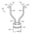
- FIGS. 6A-6Cdepict a closure device with flexible members on the distal tip and a backstop element
- FIGS. 7A-7Eillustrate several embodiments of a closure device utilizing a balloon to close a layered tissue defect
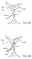
- FIGS. 8A-8Dshow how one or more catheters or guide wires may be used to close a layered tissue defect
- FIGS. 9A-9Bshow how intravascular ultrasound is used to image the layered tissue defect
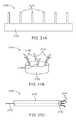
- FIG. 10A-10Cshow another embodiment of the layered tissue closure device
- FIG. 11A-1 LEillustrate a method for closing a layered tissue defect
- FIGS. 12A-12Bshows an embodiment of a closure device with a wire-like basket in both the undeployed and deployed states
- FIG. 13shows an embodiment where two wire-like baskets are used to treat a layered tissue defect
- FIGS. 14A-14Dillustrates a closure device having a fan shaped energy transmission member
- FIG. 15shows another embodiment with a cone shaped energy transmission member
- FIGS. 16A-18show basket-like embodiments
- FIG. 19shows an insulated guide wire embodiment
- FIG. 20illustrates the use of thermocouples adjacent to electrodes
- FIGS. 21A-21Cshow how electrodes may be formed from a flat sheet
- FIGS. 22A-22Cshow wire braided devices having various configurations
- FIG. 23shows another wire braided device
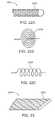
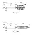
- FIGS. 24A-24Bshow how the shape of a wire braided device may be adjusted
- FIGS. 25A-25Fillustrate a method of closing a PFO in accordance with one embodiment of the present invention
- FIG. 26illustrates the use of ultrasound markers on a closure device
- FIG. 27shows horizontal sweep of an ultrasound transducer
- FIG. 28shows a PFO as imaged with ultrasound
- FIG. 29shows how ultrasound may be used to determine guide wire position in the PFO tunnel
- FIGS. 30A-30Bshows how ultrasound may be used to visualize a patent PFO tunnel and a closed PFO tunnel
- FIGS. 31A-31Billustrate how an ultrasound element on a guide wire may be used to look back from the PFO tunnel into the right atrium.
- Devices and methods of the present inventiongenerally provide for patent foramen ovale (PFO) treatment through application or removal of energy.
- Methodsinvolve advancing a catheter device to a position in the heart for treating the PFO and applying energy to (or removing energy from) tissues adjacent a PFO to substantially close the PFO acutely.
- Termssuch as “substantially,” “acutely,” and “tissues adjacent the PFO” are defined above in the Brief Summary of the Invention.
- Devices of the inventiongenerally include an elongate flexible member having a proximal end and a distal end and at least one energy transmission member deployable from the elongate flexible member for applying energy to or removing energy from tissues adjacent the PFO.
- FIG. 1is a diagram of the fetal circulation.
- the foramen ovaleis shown, with an arrow demonstrating that blood passes from the right atrium to the left atrium in the fetus.
- the foramen ovalefails to close (thus becoming a PFO)
- bloodmay travel from the right atrium to the left atrium or vice versa, causing increased risk of stroke, migraine and possibly other adverse health conditions, as discussed above.
- FIGS. 2A-2Eone embodiment of a PFO closure device 100 comprises a catheter 104 and a pair of flexible spring arms or prongs 102 attached to catheter 104 .
- FIG. 2Ashows an optional clip or staple 108 coupled to an inner shaft 110 and that is deployable from catheter 104 .
- the flexible spring arms 102are inserted into the PFO and they impart a lateral force to the PFO tissue. This lateral force serves two purposes: it rotationally orients a delivery catheter relative to the PFO, and it brings together the septum primum and septum secundum thereby positioning the PFO in its naturally closed position. Once it is held in its naturally closed position, as shown in FIG.
- a penetrating staple 108 , non-penetrating clip or other suitable devicemay be deployed from catheter 104 by advancing inner shaft 110 as seen in FIG. 2C until the staple 108 contacts the tissues of the PFO, shown in FIG. 2D .
- the staple 108is applied to permanently hold together and seal the PFO and inner shaft 110 is retracted back into catheter 104 .
- the primum and secundummay be welded together by delivering energy to either or both of the primum and septum secundum.
- FIG. 2Fillustrates another embodiment similar to that depicted in FIGS. 2A-2E , yet in this new embodiment, vacuum apertures 106 are disposed on the flexible spring arms.
- a vacuummay be applied to the PFO tissues to help appose tissue against the flexible spring arms during energy delivery and retraction of the device.
- devices of the present inventiondo not require such members.
- devicesmay include a catheter device having one or more energy transmission members for applying or removing energy, without any components designed for bringing the tissues together. Therefore, although much of the following discussion focuses on embodiments including tissue apposition members and the like, such members are not required.
- devicessuch as those described in FIGS. 2A-2C will most preferably make use of monopolar radiofrequency (RF) energy transmitted from the conductive elements of the treatment apparatus, through the patient, completing the circuit to a ground pad affixed to the external skin of the patient.
- Control systems within the energy delivery systemsmay automatically stop energy delivery upon detecting a change in condition of energy delivery, for instance an increase in electrical resistance or impedance within the closure device and/or tissues, an increased energy draw from the treatment apparatus, or a sudden temperature rise.
- bipolar RF energymay be transmitted from the treatment apparatus.
- other forms of energymay be applied to one or more closure devices and/or to tissues adjacent a PFO, such as but not limited to resistive heating, heat energy, ultrasound, microwave, laser or cryogenic energy.
- FIG. 3Ashows a distal end of one embodiment of a catheter 150 having treatment apparatus 162 comprising two conductive elements extending from a delivery sheath 160 , each having an insulated proximal portion 156 , a positive stop 152 , and an uninsulated distal energy transmission portion 154 .
- Catheter 150may also include a ground site 158 for bipolar use.
- Positive stops 152engage the peripheral limits of the PFO in order to allow passage of treatment apparatus 162 to a predetermined depth within the PFO.
- the multiple conductive elements 154may be actuatable by spring-action or through positive mechanical means such as hinges, so that the multiple conductive elements 154 can expand and apply lateral forces to the PFO, stretching the tissue of the septum primum and septum secundum apart, thereby bringing the edges of these tissue structures into apposition.
- energyis applied to the tissue as the catheter 150 is withdrawn from the PFO, thereby substantially sealing the tissue defect.
- an additional implantable closure device 157of the types described in U.S. patent application Ser. No. 10/665,974 which has previously been incorporated by reference, may span the distance between the uninsulated energy transmission portions 156 of the conductive elements. This additional implantable closure device 157 is shown in FIG. 3B .
- FIG. 4illustrates another embodiment of a closure device 200 .
- closure device 200comprises an adjustable loop element 204 which is deployed from a catheter shaft 202 and retractable into the shaft 202 .
- FIG. 4depicts adjustable loop 204 as a single electrode, although it may comprise multiple electrodes and insulation such as parylene may be deposited on various portions of the electrodes to control the conductive regions or individual electrodes may be selectively activated.
- Adjustable loop 204may be a fixed structure or it may be a dynamic structure.
- suctioncan be applied from within the lumen of a hollow loop to help appose tissue in the defect while energy is applied.
- Deploying the adjustable loop element 204allows the size of the loop to be increased or decreased to appose with the PFO tissue defect.
- the loopis enlarged 206 to accommodate a larger PFO tunnel.
- Electrodes 208 disposed on the adjustable loop 206permit energy to be delivered from the closure device 200 to the layered tissue defect. In operation, as energy is applied to the PFO the loop can be retracted so that the loop element does not become stuck or welded to the tissue.
- Typical materials used to fabricate the adjustable loop 204include a shape memory alloy such as nitinol formed of a nickel titanium alloy and spring temper stainless steels, as well as other materials such as polymers.
- FIGS. 5A-5Cshow closure device 250 with an elongated flexible catheter shaft 252 inserted into the mouth of a PFO 254 and into the PFO tunnel 256 .
- Elongated flexible electrodes 258protrude radially outward from the distal end of catheter shaft 252 .
- Energyis delivered from the closure device 250 via electrodes 258 to the tissue defect.
- the flexible electrodes 258collapse inwardly to allow the tunnel to substantially close.
- catheter 252is retracted out of and away from the PFO tunnel until the device 250 has been removed from the PFO defect.
- FIG. 5Billustrates a cross-section taken along line 5 B- 5 B ( FIG. 5A ), at the distal end of closure device 250 and shows the electrodes 258 in a fully collapsed state.
- FIG. 5Cis a perspective view of the closure device 250 of FIG. 5A .
- the closure device 250may further include a sock like covering 259 over the collapsible electrodes 258 , as illustrated in FIG. 5D .
- the sock 259may be formed of an implantable material such as collagen and may be used to facilitate closure of the layered tissue defect.
- the sock 259may also comprise a lubricious inner liner 257 that is adapted to facilitate separation of the sock 259 from the collapsible electrodes 258 .
- the closure device 250may further allow delivery of collagen to the layered tissue defect with or without a cross-linking agent such as glutaraldehyde.
- FIG. 5Eshows one such embodiment where balloons 260 , 262 are placed proximal and distal to the sock 259 . Balloons 260 , 262 are expanded to a diameter sufficient to prevent the cross-linking agent from flowing past either balloon 260 , 262 , thereby limiting the cross-linking agent to the region therebetween.
- Apparatus and methods according to the present inventionmay rely on energy, in various forms, to seal the PFO, either with or without an associated implant.
- Implantssuch as patches, self-closing elements, or the like, may be welded into place using energy in a variety of ways.
- any suitable type or configuration of welding substance, matrix, patch or the likemay be used to enhance application of energy for providing PFO closure.
- Devices and methods using various types of energy and tissue welding substances to close PFOsare described fully in U.S. patent application Ser. No. 10/665,974, which was previously incorporated by reference.
- systems according to the present inventioncan function to weld the PFO closed with no implant left behind.
- a backstop and energy delivery catheterare placed in contact with the PFO, and energy is delivered to disrupt the collagen matrix of the septum primum and septum secundum to cause fusion of the two parts of the PFO.
- Energy usedcan be monopolar RF (in which case the backstop acts as energy return, or ground electrode), or combinations thereof, ultrasound, laser, microwave, or resistance heating. Protein solder may be introduced to facilitate the weld.
- a catheter device 300 for treating a PFOmay include an outer catheter shaft 306 , an inner catheter shaft 304 slidably disposed within outer shaft 306 , a backstop 310 coupled with a backstop actuator 302 extending through inner shaft 304 , and energy delivery members 308 .
- Energy delivery members 308may deliver any suitable form of energy for providing PFO closure, such as but not limited to RF, ultrasound, laser or microwave energy.
- backstop 310may act as an energy return member, such as when bipolar RF energy is used.
- the energy delivery members 308are flexible.
- catheter device 375is used in a similar fashion as described above with respect to FIG. 6A , except that backstop 310 is inserted through the septum into the left side of the heart in order to ensure that tissue layers are apposed with one another and with energy delivery members 308 .
- an alternative embodiment of a catheter device 350may include a catheter shaft 354 , an expandable member 356 , an energy delivery member 358 disposed within expandable member 356 , and a backstop 360 coupled proximally with an actuator 352 .
- Expandable member 356 and backstop 360are used to position catheter device 350 in a desired location for treating the PFO, and energy is then applied via energy delivery member 358 .
- energy delivery member 358may comprise an ultrasonic piezo-foil, though any other suitable delivery device may be used in alternate embodiments.
- an alternative embodiment of a catheter device 400 for treating a PFOincludes a catheter body 402 , an expandable member 408 having apertures 406 for allowing passage of fluid and an energy transmission member 404 .
- the force applied by expanding expandable member 408may be sufficient to appose tissues, or a proximally directed force may be applied to expandable member 408 , such as by pulling back on catheter body 402 , to bring the tissues together.
- a catheter device 450includes a catheter body 458 , an expandable member 460 having an energy transmission member 456 disposed within it and apertures 454 on its surface for allowing passage of conductive fluid, and a shaped distal portion 452 .
- Shaped distal portion 452resides in the left atrium and acts as a surface or “backstop,” such that tissue may be brought together between shaped distal portion 452 and expandable member 460 .
- shaped portion 452is a helical coil, which may be made of shape memory material, spring stainless steel or the like, so that it has a relatively straight configuration while disposed within catheter body 458 , but assumes the coiled configuration when released.
- backstop devicesmay be used, such as those described more fully in U.S. patent application Ser. No. 11/472,923 and U.S. Provisional Patent Application No. 60/478,035, the contents of which are hereby incorporated by reference.
- FIG. 7Cshows how the expandable member 408 and 460 in FIGS. 7A and 7B respectively, may comprise energy transmission members 482 on the surface 486 of the expandable member 480 .
- the expandable memberis a balloon 480 .
- the balloon 480is mounted on the distal end of a catheter 484 .
- the energy transmission members 482are electrodes circumferentially disposed around balloon 480 .
- the electrodesalso could be disposed axially or in other patterns such as a winding helical shape.
- segmented energy transmission members 483such as electrodes may be disposed on the balloon surface 486 in order to more precisely control how energy is delivered to the treatment region.
- the balloon member 480may be placed within the tunnel of the PFO in its deflated state, inflated, energized, and as energy is being applied, deflated to allow the tissues of the PFO to contact one another as the balloon device is removed.
- the ballooncan be deflated to reduce the surface area in contact with the tissue to allow the tissues of the PFO to contact one another and form a tissue bond. Additionally, it may be desirable to pull the balloon device proximally during or after deflation to assist in bonding of the tissue.
- the balloon 480may be formed from a variety of materials, including compliant as well as non-compliant materials.
- FIG. 7Eshows a flat balloon 480 that is rectangular in shape and adapted to fit into a PFO tunnel. When expanded, the balloon exerts a lateral force against the tissues of the PFO thereby bringing the tissues together.
- FIGS. 8A-8Dillustrate embodiments where a simple elongate flexible member 504 , 554 and 586 , such as a guide wire is placed in between the primum P and secundum S layers of tissue in a PFO.
- the guide wire 504may be adapted to serve as an energy transmission member. For example, energy can be delivered into the PFO tunnel as the guide wire is retracted, thus energizing the effective region of the PFO tunnel and closing it.
- a closure device 500comprises an elongate flexible member such as a guide wire 504 .
- the distal end 502is inserted into the PFO tunnel so as to deliver energy to the tunnel.
- the guide wireis easily retracted through the PFO tunnel as energy is applied to the defect. Additionally, the guide wire may be moved back and forth around the defect as well as and in and out of the tissue defect so as to deliver energy to a wider area of the defect.
- the closure device 550comprises an elongate flexible member such as a guide wire or catheter 554 .
- the closure device 550is inserted into the PFO tunnel formed by the primum P and secundum S and the distal end 556 delivers energy to the tunnel.
- the distal end 552 of the tunnelis sealed and then the closure device 550 is removed.
- the healing process at the distal locationwill be sufficient to close the defect, or in some cases, if not sufficient due to the size of the PFO, the healing process will propagate the closure along a majority of the tunnel length.
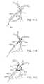
- FIG. 8Cshows a variation on the embodiments of FIGS. 8A and 8B .
- a variable resistor 584is placed in line with the guide wire 586 .
- the variable resistor 584allows an operator to adjust the energy delivered by closure device 580 to the PFO tunnel.
- An electrode 582 disposed on the guide wire 586directs energy to the layers of tissue in the PFO.
- dual guide wiresmay be used to seal the PFO tunnel.
- one guide wire 590is placed in the PFO tunnel from one side of the heart while a second guide wire 592 is placed in the PFO tunnel from an opposite side of the heart. Energy is delivered to the PFO simultaneously by both guide wires as they are retraced in opposite directions. This is illustrated in FIG. 8D .
- FIG. 19shows an alternative embodiment of a guide wire energy transmission member.
- closure device 1900comprises an elongated, flexible guide wire 1906 axially disposed in a sheath 1902 .
- the guide wire 1906is insulated 1904 along its length with the distal portion 1908 remaining uninsulated so that energy may be delivered from the tip 1908 .
- the guide wire 1906may be retracted into the sheath 1902 during delivery and then advanced into the tissue defect during the therapeutic delivery of energy.
- An axially disposed member 1910may provide a conductive pathway from the uninsulated tip 1908 back to the proximal end of the closure device 1900 . Additionally, the axially disposed member 1910 may also be used to deploy and retract the guide wire 1906 from the sheath 1902 .
- guide wire 1906may be pre-shaped to form various patterns such as sinusoidal or zig-zag configurations upon deployment from the sheath. In operation, these embodiments may allow the energized portion to effect a greater surface area within the tunnel of the PFO.
- FIGS. 9A and 9Billustrate how intravascular ultrasound (IVUS) or intracardiac echocardiography (ICE) may be employed in the PFO tunnel closure procedure.
- IVUS or ICEmay be used to image the PFO as an aid in determining the effectiveness of the closure treatment.
- IVUS and ICE methods and apparatusare well known in the art and many references may be found in the medical and patent literature. Exemplary products currently commercially available include the Atlantis® SR Pro coronary imaging catheter and Galaxy 2 TM IVUS imaging system available from Boston Scientific Corporation (Natick, Mass.), as well as Eagle EyeTM Gold, VisionsTM PV018 and RevolutionTM IVUS catheters manufactured by Volcano Corporation (Rancho Cordova, C A).
- the closure device 600comprises a closure catheter 602 adapted to deliver energy to the PFO as well as an IVUS member 604 that can image the PFO tunnel 606 .
- the IVUS member 604is integral with the closure catheter 602 .
- closure system 650has an IVUS member 654 separate from the closure catheter 652 .
- the IVUS member 654is alongside the closure catheter 652 and the IVUS member can image the PFO tunnel with ultrasound 656 before, during and after the closure procedure.
- Other imagining modalitiesmay also be employed such as fluoroscopy.
- FIG. 26illustrates a bottom view of a closure device 2600 .
- the closure device 2600comprises a housing 2604 that can appose tissues of the PFO and a central lumen 2602 exits the housing 2604 near its center.
- the central lumenmay be used to accommodate a guide wire and/or a vacuum.
- Electrodes 2606 on the bottom of the housing 2604allow energy to be transferred to or from the tissues of the PFO.
- Ultrasound markers 2608 placed on the housing 2604help a physician to observe the closure device under ultrasound.
- FIG. 27illustrates how an ultrasound transducer may be incorporated into a closure device. Incorporating ultrasound allows visualization of device position and thus helps to ensure that the closure device is properly seated against the PFO which in turn helps assure that an effective closure treatment is applied to the PFO. Current fluoroscopy and intracardiac echocardiography tools do not always provide adequate resolution to visualize a PFO.
- closure device 2700comprises a housing 2702 coupled to a catheter shaft 2706 .
- a two-dimensional ultrasound transducer 2708is also disposed in the distal portion of the housing 2702 .
- Ultrasound transducers 2708may include phased array as well as rotational transducers.
- FIG. 26Other elements of the closure device such as a central lumen 2602 and energy transmission member 2606 , as illustrated in FIG. 26 may be included in the closure device 2700 .
- the horizontal sweep 2704 of the ultrasound transducer 2708is shown.
- a PFO tunnel as observed under ultrasoundwould appear as depicted in FIG. 28 .
- the tunnel 2806 of a PFO 2800is seen formed between tissue layers 2802 and 2804 .
- the ultrasound devicemay be used to visualize guide wire position during initial placement.
- a guide wire 2902is placed in the tunnel 2912 of a PFO, in between tissue layers 2908 and 2910 .
- a closure device 2904 with ultrasound imaging capabilityis advanced over the guide wire.
- Ultrasound 2906is then used to visualize the position of the guide wire 2902 within the PFO tunnel 2912 .
- ultrasoundis used to visualize the tunnel as it is sealed.
- the closure device 3002 with ultrasound capabilityscans 3004 across the tissue defect to provide an image of a patent PFO tunnel 3010 between tissue layers 3006 , 3008 . Imaging may be conducted during the closure treatment and in FIG. 30B , an image of the closed PFO tunnel 3012 after treatment is seen.
- an ultrasound device 3110may be placed into the PFO tunnel 3108 to image back into the right side of the heart, as shown in FIGS. 31A-31B .
- an ultrasound device 3110is either incorporated as a part of a guide wire 3102 or the ultrasound device 3110 is advanced over a guide wire 3102 into the PFO tunnel 3108 , in between tissue layers 3104 and 3106 .
- the ultrasound probeimages away from the PFO tunnel 3108 , toward the right side of the heart 3112 as seen in FIG. 31B .
- ultrasound markersmay be incorporated into the closure device to enhance visualization under ultrasound, as shown in FIG. 26 above.
- the closure deviceautomatically signals a user when the markers are detected, thereby providing an indication that the closure device is properly positioned relative to the PFO tunnel.
- a PFO treatment apparatus 700suitably includes a catheter device 710 coupled with a tissue apposition member 712 at its distal end.
- One or more energy transmission members 714may be disposed through or within catheter device 710 and/or coupled with tissue apposition member 712 .
- Conductor wires 713couple energy transmission members 714 with the proximal end of the catheter device 710 .
- catheter device 710is slidably disposed over a guide catheter 720 .
- Guide catheter 720may contain one or more expandable elements 722 , such as a guide wire or the like.
- expandable elements 722 having distal tips 723may also serve as energy transmission members.
- One or more radiopaque markers 724 , 726may be included on catheter device 710 , guide catheter 720 or both.
- Catheter device 710may also include an isolation portion 728 . Tissue apposition member 712 is isolated from catheter device 710 by the isolation portion 728 , and this helps stabilize tissue apposition member 712 from movement of catheter device 710 , which prevents tissue apposition member 712 from losing its position.
- FIGS. 10B and 10Cshow cross-sectional views of apparatus 700 from the perspective of lines B-B and C-C in FIG. 10A , respectively.
- catheter device 710is shown, having a guide catheter lumen 732 , two energy transmission member lumens 734 and a vacuum lumen 736 .
- guide catheter 720includes an expandable element lumen 738 .
- Guide catheter lumen 732may sometimes be configured with an inner diameter (or “profile”) that is shaped (or “keyed”) to allow guide catheter 720 to pass easily through lumen 732 . This feature is demonstrated in FIGS. 10B and 10C , where guide catheter 720 and guide catheter lumen 732 each have an ovoid shape.
- catheter device 710includes an elongate, flexible catheter which may be advanced through the vasculature of a patient to a position in the heart for treating a PFO.
- catheter device 710may have any suitable length, diameter, cross-sectional profile and the like, and may be constructed of any suitable material.
- Tissue apposition member 712(or multiple tissue apposition members in some embodiments) is disposed at or near the distal end of catheter device 710 . Although many different types of devices may be used to bring tissues of the PFO together, in one embodiment tissue apposition member 712 is also adapted to cover the PFO. Tissue apposition member 712 may be positioned to contact adjacent PFO tissues to fully cover, or block, the opening of the PFO.
- tissue apposition member 712may help bring the PFO tissues together to assist in PFO closure simply by forming a seal or blockage over the PFO.
- tissue apposition member 712may also include one or more vacuum members for applying vacuum to the PFO tissues.
- suction lumen 736FIG. 10B
- the vacuum-application aperture(s)may have any suitable configuration, such as a continuous aperture encircling tissue apposition member 712 , multiple apertures encircling tissue apposition member 712 or in any other suitable configuration at or near its distal end, or the like.
- vacuummay be applied via a large, central lumen in tissue apposition member 712 .
- vacuum forcemay be used to bring PFO tissues together and/or to secure tissue apposition member 712 and thus catheter device 710 to the PFO tissues.
- Tissue apposition member 712may be collapsible/expandable to facilitate advancement and delivery of catheter device 710 .
- tissue apposition member 712may comprise a collapsible polymeric cover disposed over an expandable/collapsible frame.
- tissue apposition member 712may be constructed of a shape memory material, such as NiTi or another shape memory metal, spring stainless steel or the like, to allow catheter device 710 to be delivered through vasculature and then allow tissue apposition member 712 to expand to contact and appose the PFO tissues.
- catheter device 710 and tissue apposition member 712may be delivered to a location for PFO treatment through an introducer sheath.
- an angle between catheter device 710 and tissue apposition member 712may be selected to approximate a convenient angle for delivery and/or deployment.
- the angle between catheter device 710 and tissue apposition member 712may approximate the angle between the inferior vena cava and the interatrial septum. Any other configuration, combination of angles and the like is contemplated, however.
- direct steering of the angle of tissue apposition member 712 relative to catheter device 710may be employed to enhance delivery of catheter device 710 to a treatment site.
- catheter device 710may include one or more radiopaque markers 726 for facilitating visualization of the device 710 .
- Catheter device 710may also include a flexible isolation portion 728 , which in some embodiments comprises a rigid but shapeable portion disposed toward the distal end of catheter device 710 , between tissue apposition member 712 and the generally flexible proximal portion of catheter device 710 .
- Flexible isolation portion 728may help to isolate tissue apposition member 712 from some or all movement experienced by the more flexible, proximal portion of catheter device 710 , thus allowing a PFO treatment procedure to be performed without significant movement of tissue apposition member 712 .
- flexible isolation portion 728may be more flexible than the more proximal portion of catheter device 710 , thus enhancing maneuverability, shapability or the like of the position of tissue apposition member 712 relative to the more proximal portion.
- Energy transmission members 714may comprise any of a number of devices and may transmit any suitable type of energy for closing a PFO. Some types of energy which may be used, for example, include radiofrequency, cryogenic, resistive heat, direct heat, ultrasound, microwave and laser. Radiofrequency energy transmission members 714 may be either monopolar or bipolar or combinations thereof, with monopolar catheter devices also including a grounding member. Energy transmission members 714 may have any suitable configuration. For example, they may have a curved shape to approximate a radius of curvature of the PFO, as shown in FIG. 10A , which may be swept along the layered tissue defect.
- expandable elements 722 having distal tips 723also serve as energy transmission members and they may be configured for welding specific regions of the PFO tissues from within the tunnel or welding around the circumference of PFO tissues.
- energy transmission members 714are fixedly coupled with tissue apposition member 712 , while in other embodiments energy transmission members 714 are movable within tissue apposition member, for example to move about the circumference of the PFO to weld PFO tissues at multiple locations.
- tissue weldingherein is used to mean application of energy to (or removal of energy from) PFO tissues to substantially and acutely close the PFO.
- Energy transmission members 714generally provide for transfer of energy to or from PFO tissues to denature collagen in the tissues, and when the collagen is allowed to renature, with the tissues apposed, the once separated tissues bind together to form a stable tissue bridge. This stable tissue bridge substantially and acutely closes the PFO, preferably permanently.
- PFO tissuesmay, in some embodiments, be brought and held together by one or more tissue apposition members 712 .
- Energy transmission members 714provide sufficient energy transfer, for a sufficient time, to weld the tissues. The time span of energy transmission may be, for example, from about 0.5 seconds to about 15 minutes.
- Energy transmissionmay be from about 0.5 Watts to about 50 Watts, and more preferably from about 2 Watts to about 20 Watts. Any other suitable energy and timing combination may also be used.
- a PFO in a section of pig heart tissue used ex-vivo in a flowing saline test fixturewas closed by applying suction to appose the PFO tissues and applying RF energy at approximately 25 Watts for 7 minutes. RF energy application was then discontinued, but suction was continued for an additional time period to keep tissues in apposition while the tissue cooled, to allow collagen in the tissues to reorganize and bind together to form a stable tissue bridge.
- Other energy amounts, energy application times, tissue apposition times and the likeare contemplated.
- U.S. patent application Ser. No. 11/472,924, filed on Jun. 21, 2006discloses such parameters and is assigned to the assignee of the present invention, the full disclosure of which is incorporated herein by reference.
- any type of energymay be transmitted by energy transmission members 714 , some embodiments will make use of monopolar or bipolar radiofrequency (RF) energy, or combinations thereof.
- Devicesmay use monopolar radiofrequency energy, or heat, for example, wherein energy is applied simultaneously to all conductive elements, completing the circuit through an external ground pad affixed to the skin of the patient.
- bipolar energymay be applied to all conductive elements simultaneously, and the circuit completed through a ground element incorporated elsewhere on apparatus 700 .
- Further embodimentsmay include applying bipolar energy between two or more energy transmission members 714 , which are electrically isolated from one another within catheter device 710 .
- Monopolar and bipolar energy delivery and combinations of monopolar and bipolar energy delivery, termed “multipolar” energy deliveryare described in U.S.
- Control systems coupled with energy transmission members 714 or tissue apposition member 712 , or otherwise disposed within apparatus 700may sense an amount of energy delivered to PFO tissues and, optionally, may automatically stop energy delivery upon detecting a change in condition of energy delivery, for instance an increase in electrical resistance or impedance in PFO tissues or in apparatus 700 , an increased energy draw from the treatment apparatus, or a sudden temperature rise, and/or the like.
- energy deliverymay be automatically stopped when an amount of delivered energy reaches a desired level, such as an amount of energy sufficient to substantially close the PFO.
- the amount of delivered energymay be monitored by any suitable method, such as monitoring temperature or impedance in PFO tissues or the like.
- one or more sensors coupled with tissue apposition member 712 , energy transmission members 714 , or any other part of apparatus 700may be used for monitoring such indicia.
- sensor devicesinclude but are not limited to infrared sensing devices, thermistors and thermocouples.
- a control systemmay also include a microprocessor coupled with the sensors to determine when a desired amount of energy has been delivered and/or to automatically stop energy transmission.
- a microprocessormay be included in apparatus 700 which can sense, monitor and control energy delivery, thus not requiring separate sensors.
- apparatus 700include guide member 720 which can include a guide catheter, guide wire or other guide, or an alternative guide member as discussed further below.
- Guide member 720is generally a flexible catheter along which catheter device 710 may be slidably advanced to a position for PFO treatment.
- Guide catheter 710is configured to fit at least partially within a PFO and optionally through a PFO into the left atrium of the heart.
- one or more radiopaque markers 724may be included on guide catheter.
- Guide catheter 720may contain one or more expandable members 722 or other similar devices for expanding within the PFO to help bring the PFO tissues together, anchor catheter device to the PFO tissues, or both.
- a “fish mouth” or two-prong expandable member 722may be deployed within a PFO. When the two arms of the fish mouth separate, PFO-adjacent tissues are stretched laterally such that they tend to come together in the middle.
- expandable members 722may assist in PFO tissue apposition either while extending into the left atrium, while in other embodiments expandable members 722 do not extend into the left atrium.
- Other embodiments for expanding within the PFOare discussed in U.S.
- Expandable member 722may have any suitable configuration and may be constructed from any suitable materials.
- expandable member 722may be spring loaded, made of shape memory material, such as nitinol or spring stainless steel or the like.
- expandable member 722may be expanded mechanically by one or more expansion members coupled with expandable member 722 and controlled via an actuator at the proximal end of guide catheter 720 .
- expandable member 722resides within guide catheter 720 .
- Guide catheter 720may then be withdrawn to deploy expandable member 722 either within the PFO or within the left atrium to be drawn back into the PFO.
- expandable member 722has one or more pre-shaped or shapeable distal tips 723 .
- Tips 723may be used, for example, to help locate and cross the PFO. Tips 723 may also be used to contact a left atrial surface of the septum primum or other PFO tissue, so that when the expandable member 722 is pulled proximally tips 723 help bring the PFO tissues together and/or anchor apparatus 700 .
- one or more expandable members 722may include or be coupled with one or more energy transmission members.
- expandable member 722may include one or more radiofrequency transmission members for monopolar or RF transmission, or combinations thereof.
- a fish mouth expandable member 722may include a bipolar RF transmission member on each prong of the fish mouth.
- energy transmission membersmay be included in or coupled with both expandable member 722 and tissue apposition member 712 .
- some portions of the energy transmission member(s)may be insulated, to prevent unwanted energy transmission to tissues.
- a distal tip extending to contact a left atrial surface of PFO tissuesmay be insulated to prevent energy transmission from the tip.
- FIGS. 11A-11Edemonstrate a method for treating a PFO according to one embodiment of the present invention. It should be emphasized that this is merely one possible embodiment, and that many alternative methods are contemplated. For example, steps may be modified, repeated, added or deleted from the method, the order of steps may be changed, and/or the like, without departing from the scope of the invention as defined by the appended claims. Therefore, the foregoing description should not be interpreted to limit the scope of the invention in any way.
- a PFO treatment methodincludes advancing a guide member 820 through the PFO, between tissues P and S, adjacent to the PFO, the guide member 820 containing an expandable member, as depicted in FIG. 11A .
- Guide member 820is then retracted (proximally pointing arrow) to expose expanding member 822 .
- FIG. 11BExpanding member 822 may be exposed/expanded within the PFO, or may alternatively be exposed/expanded within the left atrium and pulled back into the tunnel of the PFO. Expanding member 822 may also include one or more distal tips 823 , which may help to locate the PFO, cross the PFO, appose the tissues P, S and/or to anchor guide member 820 to the tissues P, S.
- catheter device 810may be advanced over guide member 820 to a position for treatment of the PFO as shown in FIG. 11C .
- Catheter device 810typically includes a tissue apposition member 812 and one or more energy transmission members 814 . Suction may be applied using tissue apposition member 812 , left atrial pressure may be used, or both, to bring tissues P, S adjacent the PFO together, as shown in FIG. 11D . Once tissue apposition member 812 is placed and/or activated, guide member 820 and expandable member 822 may be removed through catheter device 810 , leaving the tissues P, S apposed and catheter device in place, as in FIG. 11D .
- guide member 820 and expandable member 822may be left in place during a first welding to close the majority of the PFO and then removed.
- the small patent portions of the PFO remaining after the guide member 820 and expandable member 822 are removedmay then be closed by a second weld or may be left open and allowed to close via healing or scarring.
- Tissue apposition member 812may be used to hold tissues P, S together before, during and/or after energy transmission members 814 weld the tissues T together. Such holding of the tissues together and application of energy to weld the tissues may be performed for any suitable time, such as for less than one second to many minutes. Once a sufficient amount of energy has been applied to the tissues P, S to acutely close the PFO, catheter device 810 is removed, leaving a closed PFO, as in FIG. 11E .
- the closure device 900comprises an elongate flexible catheter shaft 902 disposed in an outer sheath 901 , with the catheter shaft 902 having a wire-like radially expandable radiopaque basket 906 on its distal end.
- the wire-like basket 906may include two or more flexible members that form the basket, or the basket may be formed from a braid or a helically wound wire form.
- the closure device 900is advanced over a guide wire 904 into the PFO tunnel formed by tissue layers P and S.
- the basket 906is typically biased in the expanded position such that the profile of the basket matches the size of a PFO tunnel.
- the proximal end of the guide wire 904may be threaded into catheter shaft 902 and the distal end of catheter shaft 902 is attached to the basket 906 .
- the basket 906becomes unconstrained as shown in FIG. 12B , and then basket 906 opens up such that it electrically contacts the tissues of the PFO.
- the wire-like basket 906also acts as an electrode and allows energy to be delivered to the tissue defect. Energy may be delivered to the PFO tunnel while the closure device 900 remains stationary or as the device 900 is retracted, thus providing an “energy sweeping” method. As the PFO collapses, the basket 906 collapses as well.
- FIGS. 16A-18Other embodiments of wire-like or mesh baskets are shown in FIGS. 16A-18 .
- a mesh basket 1602is disposed on the distal end of sheath 1604 in closure device 1600 .
- the proximal and distal ends of the basket 1602are preferably curved to facilitate entry into and exiting from a PFO tunnel. Additionally, the arcuate shape accommodates varying sizes of PFO tunnels.
- An axial member 1606is slidably disposed along sheath 1604 and allows the basket 1602 to be advanced from the sheath 1604 or retracted into the sheath 1604 .
- Axial member 1606also provides electrical conductors from the proximal end of the closure device 1600 to the basket 1602 .
- Portions of the basket 1602are configured as energy transmission members and allow energy to be transferred between the basket 1602 and the tissues.
- the axial member 1606has been retracted proximally so as to retract basket 1602 back into sheath 1604 where it has a reduced profile.
- FIG. 17shows another embodiment of a wire-like or mesh basket 1702 .
- closure device 1700comprises a shaped basket unconstrained at the distal end 1702 and disposed on the distal end of sheath 1708 .
- the tapered shaped of the basket 1702accommodates varying PFO tunnel sizes.
- Basket 1702may be retracted into sheath 1708 in order to reduce the profile of closure device 1700 , especially during delivery.
- Axial member 1710is slidably disposed along sheath 1708 and is used to advance or retract basket 1702 to/from the sheath 1708 . Additionally, axial member 1710 may also serve as an electrical conductor path between the wire basket and the proximal end of closure device 1700 .
- a distal portion of the basket 1706serves as an uninsulated energy transmission member, while a proximal portion of the basket 1704 is insulated to prevent energy delivery from this part of the basket.
- a thin conformal insulating coatingis preferred so as to preserve the resilience of the device.
- Exemplary insulating materialsinclude for example parylene.
- FIG. 18A conically shaped wire-like basket is shown in FIG. 18 .
- a plurality of wiresform a basket 1802 on the distal end of closure device 1800 .
- An insulated region 1806prevents energy transmission, while an uninsulated region 1804 is adapted to deliver energy to the tissue.
- An axial member 1810allows the basket 1802 to be advanced from or retracted into sheath 1808 and also serves as an electrical conductor between the basket and the proximal end of closure device 1800 .
- a catheter system 925 for treating PFOmay include a first catheter body 926 having a first wire-like basket or expandable member 928 , a second catheter body 936 having a second wire-like basket or expandable member 934 and a guide wire 930 .
- the wire-like baskets 928 , 934generally take the same form as embodiments previously described herein, such as in FIGS. 12 , 16 A- 16 B, 17 or 18 .
- both wire-like baskets 928 , 934are coaxial and in some embodiments the wire baskets 928 , 934 may move independently of one another, while in other embodiments the wire baskets are fixed relative to one another.
- guide wire 930extends from an entry point on the patient, such as a femoral vein, through the inferior vena cava IVC, right atrium RA, PFO and left atrium LA, and then through the left ventricle, aorta, and eventually out a femoral artery.
- Catheter bodies 926 , 936may be advanced to locations in the right and left atria respectively along this guide wire.
- two guide wiresmay be used, and they may be coupled within the PFO or elsewhere within the heart. In either case, the wire-like baskets 928 , 934 are advanced into the PFO tunnel until they are adjacent to one another.
- Energymay then be delivered from the wire-like baskets to the PFO tissue defect as both catheter bodies 926 , 936 are retracted to the side of the PFO defect from which they were introduced.
- the guide wire 930is withdrawn upon completion of the treatment. This method permits the PFO tunnel to be sealed from both sides of the heart.
- FIG. 14Ashows still another embodiment of a closure treatment device 1000 .
- closure device 1000comprises a catheter body 1002 having a retractable, flexible fan shaped energy transmission member 1004 on its distal end.
- An outer sheath 1006is slidably disposed over the catheter body 1002 and may be advanced distally over the fan shaped energy transmission member 1004 to facilitate collapsing it and reducing its profile, as seen in FIG. 14B .
- the device 1000is inserted in between layers of the tissue defect, P, S and the fan shaped energy transmission member 1004 is deployed from the catheter shaft 1002 .
- the fan shaped energy transmission memberis self-sizing and matches the tunnel diameter or tissue surfaces.
- FIG. 14C and 14Dshow the fan shaped energy transmission member 1004 disposed in a PFO tunnel.
- the tunnelcloses around the energy transmission member 1004 , which in turn collapses the fan shaped energy transmission member 1104 to a lower profile.
- the energy transmission member 1004may then be retracted along the layered tissue defect, sealing the PFO as it is retracted.
- the fan shaped energy transmission member 1004may be left in the tunnel and as the tunnel closes, the force of the collapsing tunnel causes the fan shaped member 1004 to collapse.
- the fan shaped member 1004may then be retraced into the catheter body 1002 and removed form the PFO.
- FIG. 15a self-sizing cone shaped energy transmission member 1104 is used in FIG. 15 .
- the cone shaped member 1104may similarly be retracted along the PFO tunnel as energy is applied to close the defect, or it may be left in the tunnel as the tunnel collapses and then retracted into the catheter body 1102 and removed from the tunnel.
- closure device 2000comprises a plurality of electrodes 2008 extending from the distal end of sheath 2002 . Electrodes 2008 are disposed on elongated flexible beams and are used to deliver energy from the closure device to the tissue. Additionally, one or more thermocouples 2006 are also disposed on elongated flexible beams and the monitor tissue temperature. Tissue temperature is typically in the range from about 55° C. to about 150° C., often in the range from about 55° C. to about 90° C. and preferably in the range from about 65° C. to about 90° C. The electrodes 2008 as well as thermocouples 2006 may be withdrawn into the sheath 2002 when axial member 2004 is retracted proximally. Axial member 2004 also provides a conductive pathway from the electrodes 2008 and thermocouples 2006 to the proximal end of the closure device 2000 .
- electrodes 2100are formed from a flat sheet prior to attaching them to a closure device.
- flat stockis cut to form a plurality of elongated resilient fingers 2104 attached to a base 2102 .
- the flat stockmay also be machined, laser cut, EDM machined or photochemically etched.
- FIG. 21Bthe flat sheet of electrodes 2100 is rolled and ends are joined together so as to form an electrode ring. Portions of the electrode resilient fingers 2104 may then be insulated 2108 while uninsulated regions 2106 permit energy transmission to or from the tissue.
- the resilient electrode fingers 2104are typically insulated with a thin, conformal insulation which can be sprayed on or vapor deposition may also be employed.
- ElectrodesOnce the electrodes have been formed, they are joined to the distal end of a closure device 2150 as shown in FIG. 21C . Typically the electrodes are connected to a catheter shaft 2152 which allows the electrodes to be advanced or retracted in the vascular system. A conductor 2154 allows energy to be supplied from the proximal end of catheter shaft 2152 to the electrode fingers 2104 .
- FIGS. 22A-22C and FIG. 23Other wire mesh or braided configurations are illustrated in FIGS. 22A-22C and FIG. 23 .
- the distal end of a closure device 2200may comprise a wire-braid 2202 or mesh like tip having a cylindrical cross-section.
- the mesh structurecould also include a coiled structure 2204 as shown in FIG. 22B or a helical structure 2206 illustrated in FIG. 22C .
- FIG. 23shows how the cross-section of a closure device 2300 may easily be modified, here shown as a rectangular section 2302 .
- the wire-braid or mesh structuremay serve as an energy transmission member to transfer energy to or from the PFO during treatment.
- portions of the wire meshmay be insulated with a thin conformal coating such as parylene so that energy may be directed to specific portions of the wire mesh.
- the wire-meshmay remain uninsulated so that energy is delivered along the entire length of the wire mesh.
- Portions of the energy transmission membermay also be formed such as a laterally extending electrode as described in U.S. patent application Ser. No. 10/952,492 the entire contents of which are incorporated herein by reference.
- a close device 2400comprises a wire braid distal tip 2402 having a short cylindrical profile.
- the proximal end of the wire braid 2410is coupled to an inner shaft 2408 and a rigid wire 2406 is coupled with the distal end of the wire mesh 2404 .
- the entire assemblyis deployable from a sheath 2412 .
- the shape of the wire meshmay be adjusted as seen in FIG. 24B .
- wire 2406has been pushed distally, elongating the wire mesh and reducing its diameter into a longer, smaller diameter cylinder 2403 as compared with its original shape 2402 .
- itmay be adjusted to provide a lateral force to the PFO which would help bring the tissues into apposition with an electrode or other energy transmission member.
- Other embodiments described hereinmay similarly be used.
- FIGS. 25A-25Fillustrate a method of treating a layered tissue defect such as a PFO in accordance with another embodiment of the present invention.
- a guide wire 2504is advanced through the patient's vasculature into the right side of a patient's heart.
- the guide wire 2504is advanced between tissue layers T forming the PFO tunnel 2502 .
- Guide wire 2504 positionmay be monitored under fluoroscopy or using intracardiac ultrasound.
- the guide wire 2504is also an electrode which can then deliver energy to the tissue to close the PFO, and this has been discussed with respect to FIGS. 8A-8D above.
- the guide wire 2504once the guide wire 2504 has been successfully placed in the PFO, it acts as a guide rail as shown in FIG.
- FIG. 25Bwhere catheter 2506 is advanced over the guide wire 2504 until it is in apposition with tissues T of the PFO.
- An energy transmission wire 2508 similar to the embodiment of FIG. 8Ais then advanced through the catheter 2506 into the PFO tunnel 2502 and the original guide wire 2504 is removed, as illustrated in FIG. 25C .
- the energy transmission wire 2508is insulated along its length except for a region approximately 0.5 cm to 1 cm away from the distal end of the energy transmission wire 2508 .
- the energy transmission wire 2508is inserted into the tunnel 2502 such that the uninsulated region is adjacent to the PFO tunnel exit closest to the left side of the heart, although in some embodiments, the energy transmission wire 2508 could be inserted so that it is co-terminus with the PFO tunnel exit.
- catheter 2506applies a vacuum to the tissues T of the PFO in order to draw the tissues T toward the energy transmission wire 2508 .
- a backstop element 2510may be placed on the left side of the PFO tunnel in order to block the exit and help the suction collapse the tunnel 2502 .
- monopolar radiofrequency energyis delivered from the energy transmission wire 2508 to the tissues T of the PFO. The radiofrequency energy generates heat which in turn collapses and fuses the tissues T of the tunnel together 2512 .
- the energy transmission member 2508is retracted proximally out of the tunnel 2502 , and thus the tunnel becomes sealed along its length 2512 as seen in FIG. 25F .
- a temperature monitoring devicesuch as a thermistor or thermocouple 2514 may be placed on the energy transmission wire 2508 to allow monitoring of the treatment. After the PFO tunnel has been sealed, the wire and catheter may be removed from the patient.
- tissues adjacent the PFOare brought at least partially together and energy is applied to the tissues to acutely close the PFO with fewer steps and/or fewer device components than described.
- energyis applied to the tissues to acutely close the PFO with fewer steps and/or fewer device components than described.
- suction to appose tissuesis not required in all embodiments.
- a variety of different types of energymay be applied to the tissues from a variety of differently configured energy transmission devices.
- one or more of the steps described abovemay be repeated one or more times, such as by repeating a tissue welding step.
- energy transmission membersmay be swept along the tissues of the defect to cause a closure in the defect, or they also may be placed in the PFO tunnel and retracted during energy delivery and sealing of the tunnel.
Landscapes
- Health & Medical Sciences (AREA)
- Life Sciences & Earth Sciences (AREA)
- Surgery (AREA)
- Engineering & Computer Science (AREA)
- Plasma & Fusion (AREA)
- Medical Informatics (AREA)
- Otolaryngology (AREA)
- Physics & Mathematics (AREA)
- Cardiology (AREA)
- Biomedical Technology (AREA)
- Heart & Thoracic Surgery (AREA)
- Nuclear Medicine, Radiotherapy & Molecular Imaging (AREA)
- Molecular Biology (AREA)
- Animal Behavior & Ethology (AREA)
- General Health & Medical Sciences (AREA)
- Public Health (AREA)
- Veterinary Medicine (AREA)
- Surgical Instruments (AREA)
Abstract
Description
Claims (21)
Priority Applications (1)
| Application Number | Priority Date | Filing Date | Title |
|---|---|---|---|
| US11/613,415US7972330B2 (en) | 2003-03-27 | 2006-12-20 | Methods and apparatus for closing a layered tissue defect |
Applications Claiming Priority (6)
| Application Number | Priority Date | Filing Date | Title |
|---|---|---|---|
| US45885403P | 2003-03-27 | 2003-03-27 | |
| US47803503P | 2003-06-11 | 2003-06-11 | |
| US49008203P | 2003-07-24 | 2003-07-24 | |
| US10/679,245US6939348B2 (en) | 2003-03-27 | 2003-10-02 | Energy based devices and methods for treatment of patent foramen ovale |
| US10/958,533US20050080406A1 (en) | 2003-03-27 | 2004-10-04 | Energy based devices and methods for treatment of patent foramen ovale |
| US11/613,415US7972330B2 (en) | 2003-03-27 | 2006-12-20 | Methods and apparatus for closing a layered tissue defect |
Related Parent Applications (1)
| Application Number | Title | Priority Date | Filing Date |
|---|---|---|---|
| US10/958,533Continuation-In-PartUS20050080406A1 (en) | 2003-03-27 | 2004-10-04 | Energy based devices and methods for treatment of patent foramen ovale |
Publications (2)
| Publication Number | Publication Date |
|---|---|
| US20070123851A1 US20070123851A1 (en) | 2007-05-31 |
| US7972330B2true US7972330B2 (en) | 2011-07-05 |
Family
ID=37495101
Family Applications (1)
| Application Number | Title | Priority Date | Filing Date |
|---|---|---|---|
| US11/613,415Expired - Fee RelatedUS7972330B2 (en) | 2003-03-27 | 2006-12-20 | Methods and apparatus for closing a layered tissue defect |
Country Status (1)
| Country | Link |
|---|---|
| US (1) | US7972330B2 (en) |
Cited By (124)
| Publication number | Priority date | Publication date | Assignee | Title |
|---|---|---|---|---|
| US20110152859A1 (en)* | 2009-12-18 | 2011-06-23 | Ethicon Endo-Surgery, Inc. | Surgical instrument comprising an electrode |
| US20130066341A1 (en)* | 2011-09-13 | 2013-03-14 | Abbott Cardiovascular Systems, Inc. | Independent gripper |
| US8403926B2 (en) | 2008-06-05 | 2013-03-26 | Ethicon Endo-Surgery, Inc. | Manually articulating devices |
| US8425505B2 (en) | 2007-02-15 | 2013-04-23 | Ethicon Endo-Surgery, Inc. | Electroporation ablation apparatus, system, and method |
| US8496574B2 (en) | 2009-12-17 | 2013-07-30 | Ethicon Endo-Surgery, Inc. | Selectively positionable camera for surgical guide tube assembly |
| US8506564B2 (en) | 2009-12-18 | 2013-08-13 | Ethicon Endo-Surgery, Inc. | Surgical instrument comprising an electrode |
| US8579897B2 (en) | 2007-11-21 | 2013-11-12 | Ethicon Endo-Surgery, Inc. | Bipolar forceps |
| US8608652B2 (en) | 2009-11-05 | 2013-12-17 | Ethicon Endo-Surgery, Inc. | Vaginal entry surgical devices, kit, system, and method |
| US8771260B2 (en) | 2008-05-30 | 2014-07-08 | Ethicon Endo-Surgery, Inc. | Actuating and articulating surgical device |
| US8880185B2 (en) | 2010-06-11 | 2014-11-04 | Boston Scientific Scimed, Inc. | Renal denervation and stimulation employing wireless vascular energy transfer arrangement |
| US8906035B2 (en) | 2008-06-04 | 2014-12-09 | Ethicon Endo-Surgery, Inc. | Endoscopic drop off bag |
| US8939970B2 (en) | 2004-09-10 | 2015-01-27 | Vessix Vascular, Inc. | Tuned RF energy and electrical tissue characterization for selective treatment of target tissues |
| US8939897B2 (en) | 2007-10-31 | 2015-01-27 | Ethicon Endo-Surgery, Inc. | Methods for closing a gastrotomy |
| US8945177B2 (en) | 2011-09-13 | 2015-02-03 | Abbott Cardiovascular Systems Inc. | Gripper pusher mechanism for tissue apposition systems |
| US8951251B2 (en) | 2011-11-08 | 2015-02-10 | Boston Scientific Scimed, Inc. | Ostial renal nerve ablation |
| US8974451B2 (en) | 2010-10-25 | 2015-03-10 | Boston Scientific Scimed, Inc. | Renal nerve ablation using conductive fluid jet and RF energy |
| US9005198B2 (en) | 2010-01-29 | 2015-04-14 | Ethicon Endo-Surgery, Inc. | Surgical instrument comprising an electrode |
| US9011431B2 (en) | 2009-01-12 | 2015-04-21 | Ethicon Endo-Surgery, Inc. | Electrical ablation devices |
| US9023034B2 (en) | 2010-11-22 | 2015-05-05 | Boston Scientific Scimed, Inc. | Renal ablation electrode with force-activatable conduction apparatus |
| US9028485B2 (en) | 2010-11-15 | 2015-05-12 | Boston Scientific Scimed, Inc. | Self-expanding cooling electrode for renal nerve ablation |
| US9028472B2 (en) | 2011-12-23 | 2015-05-12 | Vessix Vascular, Inc. | Methods and apparatuses for remodeling tissue of or adjacent to a body passage |
| US9050106B2 (en) | 2011-12-29 | 2015-06-09 | Boston Scientific Scimed, Inc. | Off-wall electrode device and methods for nerve modulation |
| US9060761B2 (en) | 2010-11-18 | 2015-06-23 | Boston Scientific Scime, Inc. | Catheter-focused magnetic field induced renal nerve ablation |
| US9078662B2 (en) | 2012-07-03 | 2015-07-14 | Ethicon Endo-Surgery, Inc. | Endoscopic cap electrode and method for using the same |
| US9079000B2 (en) | 2011-10-18 | 2015-07-14 | Boston Scientific Scimed, Inc. | Integrated crossing balloon catheter |
| US9084609B2 (en) | 2010-07-30 | 2015-07-21 | Boston Scientific Scime, Inc. | Spiral balloon catheter for renal nerve ablation |
| US9089350B2 (en) | 2010-11-16 | 2015-07-28 | Boston Scientific Scimed, Inc. | Renal denervation catheter with RF electrode and integral contrast dye injection arrangement |
| US9119632B2 (en) | 2011-11-21 | 2015-09-01 | Boston Scientific Scimed, Inc. | Deflectable renal nerve ablation catheter |
| US9119600B2 (en) | 2011-11-15 | 2015-09-01 | Boston Scientific Scimed, Inc. | Device and methods for renal nerve modulation monitoring |
| US9125666B2 (en) | 2003-09-12 | 2015-09-08 | Vessix Vascular, Inc. | Selectable eccentric remodeling and/or ablation of atherosclerotic material |
| US9125667B2 (en) | 2004-09-10 | 2015-09-08 | Vessix Vascular, Inc. | System for inducing desirable temperature effects on body tissue |
| US9155589B2 (en) | 2010-07-30 | 2015-10-13 | Boston Scientific Scimed, Inc. | Sequential activation RF electrode set for renal nerve ablation |
| US9162046B2 (en) | 2011-10-18 | 2015-10-20 | Boston Scientific Scimed, Inc. | Deflectable medical devices |
| US9173696B2 (en) | 2012-09-17 | 2015-11-03 | Boston Scientific Scimed, Inc. | Self-positioning electrode system and method for renal nerve modulation |
| US9186209B2 (en) | 2011-07-22 | 2015-11-17 | Boston Scientific Scimed, Inc. | Nerve modulation system having helical guide |
| US9186210B2 (en) | 2011-10-10 | 2015-11-17 | Boston Scientific Scimed, Inc. | Medical devices including ablation electrodes |
| US9192790B2 (en) | 2010-04-14 | 2015-11-24 | Boston Scientific Scimed, Inc. | Focused ultrasonic renal denervation |
| US9192435B2 (en) | 2010-11-22 | 2015-11-24 | Boston Scientific Scimed, Inc. | Renal denervation catheter with cooled RF electrode |
| US9220526B2 (en) | 2008-11-25 | 2015-12-29 | Ethicon Endo-Surgery, Inc. | Rotational coupling device for surgical instrument with flexible actuators |
| US9220561B2 (en) | 2011-01-19 | 2015-12-29 | Boston Scientific Scimed, Inc. | Guide-compatible large-electrode catheter for renal nerve ablation with reduced arterial injury |
| US9220558B2 (en) | 2010-10-27 | 2015-12-29 | Boston Scientific Scimed, Inc. | RF renal denervation catheter with multiple independent electrodes |
| US9233241B2 (en) | 2011-02-28 | 2016-01-12 | Ethicon Endo-Surgery, Inc. | Electrical ablation devices and methods |
| US9254169B2 (en) | 2011-02-28 | 2016-02-09 | Ethicon Endo-Surgery, Inc. | Electrical ablation devices and methods |
| US9265969B2 (en) | 2011-12-21 | 2016-02-23 | Cardiac Pacemakers, Inc. | Methods for modulating cell function |
| US9277955B2 (en) | 2010-04-09 | 2016-03-08 | Vessix Vascular, Inc. | Power generating and control apparatus for the treatment of tissue |
| US9277957B2 (en) | 2012-08-15 | 2016-03-08 | Ethicon Endo-Surgery, Inc. | Electrosurgical devices and methods |
| US9297845B2 (en) | 2013-03-15 | 2016-03-29 | Boston Scientific Scimed, Inc. | Medical devices and methods for treatment of hypertension that utilize impedance compensation |
| US9314620B2 (en) | 2011-02-28 | 2016-04-19 | Ethicon Endo-Surgery, Inc. | Electrical ablation devices and methods |
| US9326751B2 (en) | 2010-11-17 | 2016-05-03 | Boston Scientific Scimed, Inc. | Catheter guidance of external energy for renal denervation |
| US9327100B2 (en) | 2008-11-14 | 2016-05-03 | Vessix Vascular, Inc. | Selective drug delivery in a lumen |
| US9358365B2 (en) | 2010-07-30 | 2016-06-07 | Boston Scientific Scimed, Inc. | Precision electrode movement control for renal nerve ablation |
| US9364284B2 (en) | 2011-10-12 | 2016-06-14 | Boston Scientific Scimed, Inc. | Method of making an off-wall spacer cage |
| US9408661B2 (en) | 2010-07-30 | 2016-08-09 | Patrick A. Haverkost | RF electrodes on multiple flexible wires for renal nerve ablation |
| US9420955B2 (en) | 2011-10-11 | 2016-08-23 | Boston Scientific Scimed, Inc. | Intravascular temperature monitoring system and method |
| US9427255B2 (en) | 2012-05-14 | 2016-08-30 | Ethicon Endo-Surgery, Inc. | Apparatus for introducing a steerable camera assembly into a patient |
| US9433760B2 (en) | 2011-12-28 | 2016-09-06 | Boston Scientific Scimed, Inc. | Device and methods for nerve modulation using a novel ablation catheter with polymeric ablative elements |
| CN105960260A (en)* | 2014-01-31 | 2016-09-21 | 美敦力 | Accessory to allow sensing at balloon interface |
| US9463062B2 (en) | 2010-07-30 | 2016-10-11 | Boston Scientific Scimed, Inc. | Cooled conductive balloon RF catheter for renal nerve ablation |
| US9486355B2 (en) | 2005-05-03 | 2016-11-08 | Vessix Vascular, Inc. | Selective accumulation of energy with or without knowledge of tissue topography |
| US9486270B2 (en) | 2002-04-08 | 2016-11-08 | Medtronic Ardian Luxembourg S.A.R.L. | Methods and apparatus for bilateral renal neuromodulation |
| US9545290B2 (en) | 2012-07-30 | 2017-01-17 | Ethicon Endo-Surgery, Inc. | Needle probe guide |
| US9572623B2 (en) | 2012-08-02 | 2017-02-21 | Ethicon Endo-Surgery, Inc. | Reusable electrode and disposable sheath |
| US9579149B2 (en) | 2014-03-13 | 2017-02-28 | Medtronic Ardian Luxembourg S.A.R.L. | Low profile catheter assemblies and associated systems and methods |
| US9579030B2 (en) | 2011-07-20 | 2017-02-28 | Boston Scientific Scimed, Inc. | Percutaneous devices and methods to visualize, target and ablate nerves |
| US9649156B2 (en) | 2010-12-15 | 2017-05-16 | Boston Scientific Scimed, Inc. | Bipolar off-wall electrode device for renal nerve ablation |
| US9668811B2 (en) | 2010-11-16 | 2017-06-06 | Boston Scientific Scimed, Inc. | Minimally invasive access for renal nerve ablation |
| US9687166B2 (en) | 2013-10-14 | 2017-06-27 | Boston Scientific Scimed, Inc. | High resolution cardiac mapping electrode array catheter |
| US9693821B2 (en) | 2013-03-11 | 2017-07-04 | Boston Scientific Scimed, Inc. | Medical devices for modulating nerves |
| US9707036B2 (en) | 2013-06-25 | 2017-07-18 | Boston Scientific Scimed, Inc. | Devices and methods for nerve modulation using localized indifferent electrodes |
| US9713730B2 (en) | 2004-09-10 | 2017-07-25 | Boston Scientific Scimed, Inc. | Apparatus and method for treatment of in-stent restenosis |
| US9757193B2 (en) | 2002-04-08 | 2017-09-12 | Medtronic Ardian Luxembourg S.A.R.L. | Balloon catheter apparatus for renal neuromodulation |
| US9770606B2 (en) | 2013-10-15 | 2017-09-26 | Boston Scientific Scimed, Inc. | Ultrasound ablation catheter with cooling infusion and centering basket |
| US9808311B2 (en) | 2013-03-13 | 2017-11-07 | Boston Scientific Scimed, Inc. | Deflectable medical devices |
| US9808300B2 (en) | 2006-05-02 | 2017-11-07 | Boston Scientific Scimed, Inc. | Control of arterial smooth muscle tone |
| US9827040B2 (en) | 2002-04-08 | 2017-11-28 | Medtronic Adrian Luxembourg S.a.r.l. | Methods and apparatus for intravascularly-induced neuromodulation |
| US9827039B2 (en) | 2013-03-15 | 2017-11-28 | Boston Scientific Scimed, Inc. | Methods and apparatuses for remodeling tissue of or adjacent to a body passage |
| US9833283B2 (en) | 2013-07-01 | 2017-12-05 | Boston Scientific Scimed, Inc. | Medical devices for renal nerve ablation |
| US9883910B2 (en) | 2011-03-17 | 2018-02-06 | Eticon Endo-Surgery, Inc. | Hand held surgical device for manipulating an internal magnet assembly within a patient |
| US9895191B2 (en)* | 2010-06-28 | 2018-02-20 | Medtronic Advanced Energy Llc | Electrode sheath for electrosurgical device |
| US9895194B2 (en) | 2013-09-04 | 2018-02-20 | Boston Scientific Scimed, Inc. | Radio frequency (RF) balloon catheter having flushing and cooling capability |
| US9907609B2 (en) | 2014-02-04 | 2018-03-06 | Boston Scientific Scimed, Inc. | Alternative placement of thermal sensors on bipolar electrode |
| US9919144B2 (en) | 2011-04-08 | 2018-03-20 | Medtronic Adrian Luxembourg S.a.r.l. | Iontophoresis drug delivery system and method for denervation of the renal sympathetic nerve and iontophoretic drug delivery |
| US9925001B2 (en) | 2013-07-19 | 2018-03-27 | Boston Scientific Scimed, Inc. | Spiral bipolar electrode renal denervation balloon |
| US9943365B2 (en) | 2013-06-21 | 2018-04-17 | Boston Scientific Scimed, Inc. | Renal denervation balloon catheter with ride along electrode support |
| US9956029B2 (en) | 2014-10-31 | 2018-05-01 | Medtronic Advanced Energy Llc | Telescoping device with saline irrigation line |
| US9956033B2 (en) | 2013-03-11 | 2018-05-01 | Boston Scientific Scimed, Inc. | Medical devices for modulating nerves |
| US9962223B2 (en) | 2013-10-15 | 2018-05-08 | Boston Scientific Scimed, Inc. | Medical device balloon |
| US9974607B2 (en) | 2006-10-18 | 2018-05-22 | Vessix Vascular, Inc. | Inducing desirable temperature effects on body tissue |
| US10022182B2 (en) | 2013-06-21 | 2018-07-17 | Boston Scientific Scimed, Inc. | Medical devices for renal nerve ablation having rotatable shafts |
| US10085799B2 (en) | 2011-10-11 | 2018-10-02 | Boston Scientific Scimed, Inc. | Off-wall electrode device and methods for nerve modulation |
| US10092291B2 (en) | 2011-01-25 | 2018-10-09 | Ethicon Endo-Surgery, Inc. | Surgical instrument with selectively rigidizable features |
| US10098527B2 (en) | 2013-02-27 | 2018-10-16 | Ethidcon Endo-Surgery, Inc. | System for performing a minimally invasive surgical procedure |
| US10105141B2 (en) | 2008-07-14 | 2018-10-23 | Ethicon Endo-Surgery, Inc. | Tissue apposition clip application methods |
| US10265122B2 (en) | 2013-03-15 | 2019-04-23 | Boston Scientific Scimed, Inc. | Nerve ablation devices and related methods of use |
| US10271898B2 (en) | 2013-10-25 | 2019-04-30 | Boston Scientific Scimed, Inc. | Embedded thermocouple in denervation flex circuit |
| US10293190B2 (en) | 2002-04-08 | 2019-05-21 | Medtronic Ardian Luxembourg S.A.R.L. | Thermally-induced renal neuromodulation and associated systems and methods |
| US10314649B2 (en) | 2012-08-02 | 2019-06-11 | Ethicon Endo-Surgery, Inc. | Flexible expandable electrode and method of intraluminal delivery of pulsed power |
| US10321946B2 (en) | 2012-08-24 | 2019-06-18 | Boston Scientific Scimed, Inc. | Renal nerve modulation devices with weeping RF ablation balloons |
| US10335280B2 (en) | 2000-01-19 | 2019-07-02 | Medtronic, Inc. | Method for ablating target tissue of a patient |
| US10342609B2 (en) | 2013-07-22 | 2019-07-09 | Boston Scientific Scimed, Inc. | Medical devices for renal nerve ablation |
| US10350004B2 (en) | 2004-12-09 | 2019-07-16 | Twelve, Inc. | Intravascular treatment catheters |
| US10398464B2 (en) | 2012-09-21 | 2019-09-03 | Boston Scientific Scimed, Inc. | System for nerve modulation and innocuous thermal gradient nerve block |
| US10413357B2 (en) | 2013-07-11 | 2019-09-17 | Boston Scientific Scimed, Inc. | Medical device with stretchable electrode assemblies |
| US10549127B2 (en) | 2012-09-21 | 2020-02-04 | Boston Scientific Scimed, Inc. | Self-cooling ultrasound ablation catheter |
| US10588682B2 (en) | 2011-04-25 | 2020-03-17 | Medtronic Ardian Luxembourg S.A.R.L. | Apparatus and methods related to constrained deployment of cryogenic balloons for limited cryogenic ablation of vessel walls |
| US10589130B2 (en) | 2006-05-25 | 2020-03-17 | Medtronic, Inc. | Methods of using high intensity focused ultrasound to form an ablated tissue area containing a plurality of lesions |
| US10624618B2 (en) | 2001-06-27 | 2020-04-21 | Evalve, Inc. | Methods and devices for capturing and fixing leaflets in valve repair |
| US10631871B2 (en) | 2003-05-19 | 2020-04-28 | Evalve, Inc. | Fixation devices, systems and methods for engaging tissue |
| US10631914B2 (en) | 2013-09-30 | 2020-04-28 | Covidien Lp | Bipolar electrosurgical instrument with movable electrode and related systems and methods |
| US10660703B2 (en) | 2012-05-08 | 2020-05-26 | Boston Scientific Scimed, Inc. | Renal nerve modulation devices |
| US10660698B2 (en) | 2013-07-11 | 2020-05-26 | Boston Scientific Scimed, Inc. | Devices and methods for nerve modulation |
| US10695124B2 (en) | 2013-07-22 | 2020-06-30 | Boston Scientific Scimed, Inc. | Renal nerve ablation catheter having twist balloon |
| US10709490B2 (en) | 2014-05-07 | 2020-07-14 | Medtronic Ardian Luxembourg S.A.R.L. | Catheter assemblies comprising a direct heating element for renal neuromodulation and associated systems and methods |
| US10722300B2 (en) | 2013-08-22 | 2020-07-28 | Boston Scientific Scimed, Inc. | Flexible circuit having improved adhesion to a renal nerve modulation balloon |
| US10779882B2 (en) | 2009-10-28 | 2020-09-22 | Ethicon Endo-Surgery, Inc. | Electrical ablation devices |
| US10835305B2 (en) | 2012-10-10 | 2020-11-17 | Boston Scientific Scimed, Inc. | Renal nerve modulation devices and methods |
| US10893941B2 (en) | 2015-04-02 | 2021-01-19 | Abbott Cardiovascular Systems, Inc. | Tissue fixation devices and methods |
| US10945786B2 (en) | 2013-10-18 | 2021-03-16 | Boston Scientific Scimed, Inc. | Balloon catheters with flexible conducting wires and related methods of use and manufacture |
| US10952790B2 (en) | 2013-09-13 | 2021-03-23 | Boston Scientific Scimed, Inc. | Ablation balloon with vapor deposited cover layer |
| US11000679B2 (en) | 2014-02-04 | 2021-05-11 | Boston Scientific Scimed, Inc. | Balloon protection and rewrapping devices and related methods of use |
| US11202671B2 (en) | 2014-01-06 | 2021-12-21 | Boston Scientific Scimed, Inc. | Tear resistant flex circuit assembly |
| US11246654B2 (en) | 2013-10-14 | 2022-02-15 | Boston Scientific Scimed, Inc. | Flexible renal nerve ablation devices and related methods of use and manufacture |
| US11850151B2 (en) | 2019-07-15 | 2023-12-26 | Evalve, Inc. | Proximal element actuator fixation and release mechanisms |
| US12048624B2 (en) | 2019-07-15 | 2024-07-30 | Evalve, Inc. | Independent proximal element actuation methods |
Families Citing this family (59)
| Publication number | Priority date | Publication date | Assignee | Title |
|---|---|---|---|---|
| US7713190B2 (en) | 1998-02-24 | 2010-05-11 | Hansen Medical, Inc. | Flexible instrument |
| US6626899B2 (en) | 1999-06-25 | 2003-09-30 | Nidus Medical, Llc | Apparatus and methods for treating tissue |
| US6702835B2 (en) | 2001-09-07 | 2004-03-09 | Core Medical, Inc. | Needle apparatus for closing septal defects and methods for using such apparatus |
| US20060052821A1 (en) | 2001-09-06 | 2006-03-09 | Ovalis, Inc. | Systems and methods for treating septal defects |
| US6776784B2 (en) | 2001-09-06 | 2004-08-17 | Core Medical, Inc. | Clip apparatus for closing septal defects and methods of use |
| US20070129755A1 (en)* | 2005-12-05 | 2007-06-07 | Ovalis, Inc. | Clip-based systems and methods for treating septal defects |
| US20050267495A1 (en)* | 2004-05-17 | 2005-12-01 | Gateway Medical, Inc. | Systems and methods for closing internal tissue defects |
| WO2004000098A2 (en) | 2002-06-19 | 2003-12-31 | Palomar Medical Technologies, Inc. | Method and apparatus for treatment of cutaneous and subcutaneous conditions |
| US7165552B2 (en) | 2003-03-27 | 2007-01-23 | Cierra, Inc. | Methods and apparatus for treatment of patent foramen ovale |
| AU2004226374B2 (en) | 2003-03-27 | 2009-11-12 | Terumo Kabushiki Kaisha | Methods and apparatus for treatment of patent foramen ovale |
| US6939348B2 (en)* | 2003-03-27 | 2005-09-06 | Cierra, Inc. | Energy based devices and methods for treatment of patent foramen ovale |
| US7293562B2 (en) | 2003-03-27 | 2007-11-13 | Cierra, Inc. | Energy based devices and methods for treatment of anatomic tissue defects |
| US8007511B2 (en) | 2003-06-06 | 2011-08-30 | Hansen Medical, Inc. | Surgical instrument design |
| US7976539B2 (en)* | 2004-03-05 | 2011-07-12 | Hansen Medical, Inc. | System and method for denaturing and fixing collagenous tissue |
| WO2005087128A1 (en) | 2004-03-05 | 2005-09-22 | Hansen Medical, Inc. | Robotic catheter system |
| US7856985B2 (en) | 2005-04-22 | 2010-12-28 | Cynosure, Inc. | Method of treatment body tissue using a non-uniform laser beam |
| JP2009500086A (en) | 2005-07-01 | 2009-01-08 | ハンセン メディカル,インク. | Robotic guide catheter system |
| US8579936B2 (en) | 2005-07-05 | 2013-11-12 | ProMed, Inc. | Centering of delivery devices with respect to a septal defect |
| US7799023B2 (en)* | 2005-09-26 | 2010-09-21 | Coherex Medical, Inc. | Compliant electrode for patent foramen ovale closure device |
| US8221405B2 (en)* | 2006-02-06 | 2012-07-17 | Coherex Medical, Inc. | Patent foramen ovale closure device and methods for determining RF dose for patent foramen ovale closure |
| EP1986559B1 (en) | 2006-02-24 | 2012-03-28 | Terumo Kabushiki Kaisha | Pfo closing device |
| US8402974B2 (en)* | 2006-05-30 | 2013-03-26 | Coherex Medical, Inc. | Methods, systems, and devices for sensing, measuring, and controlling closure of a patent foramen ovale |
| US7938826B2 (en)* | 2006-05-30 | 2011-05-10 | Coherex Medical, Inc. | Methods, systems, and devices for closing a patent foramen ovale using mechanical structures |
| US7586957B2 (en) | 2006-08-02 | 2009-09-08 | Cynosure, Inc | Picosecond laser apparatus and methods for its operation and use |
| US20080140113A1 (en)* | 2006-12-07 | 2008-06-12 | Cierra, Inc. | Method for sealing a pfo using an energy delivery device |
| US20080140074A1 (en)* | 2006-12-07 | 2008-06-12 | Cierra, Inc. | Multi-electrode apparatus for tissue welding and ablation |
| US20080154286A1 (en)* | 2006-12-21 | 2008-06-26 | Ryan Abbott | Systems and Methods for Treating Septal Defects with Capture Devices and Other Devices |
| WO2008154007A1 (en)* | 2007-06-08 | 2008-12-18 | Cynosure, Inc. | Surgical waveguide |
| US8394090B2 (en) | 2007-06-25 | 2013-03-12 | Terumo Kabushiki Kaisha | Medical device |
| EP2008600B1 (en)* | 2007-06-25 | 2010-09-22 | Terumo Kabushiki Kaisha | Medical device |
| EP2184019B1 (en)* | 2007-08-28 | 2015-12-09 | Terumo Kabushiki Kaisha | Device for opening/closing biological tissue |
| JP2009050589A (en)* | 2007-08-28 | 2009-03-12 | Terumo Corp | Pfo closing device |
| WO2009028542A1 (en)* | 2007-08-28 | 2009-03-05 | Terumo Kabushiki Kaisha | Medical device |
| JP2009050588A (en)* | 2007-08-28 | 2009-03-12 | Terumo Corp | Pfo closing device |
| US20090118726A1 (en)* | 2007-10-05 | 2009-05-07 | Coaptus Medical Corporation | Systems and Methods for Transeptal Cardiac Procedures, Including Tissue Sealing Members Associated Methods |
| US20100036294A1 (en) | 2008-05-07 | 2010-02-11 | Robert Mantell | Radially-Firing Electrohydraulic Lithotripsy Probe |
| US9254123B2 (en) | 2009-04-29 | 2016-02-09 | Hansen Medical, Inc. | Flexible and steerable elongate instruments with shape control and support elements |
| US20110218503A1 (en)* | 2010-03-03 | 2011-09-08 | Coaptus Medical Corporation | Systems and methods for transeptal cardiac procedures, including adjustable, separable guidewires |
| US8480710B2 (en)* | 2010-11-04 | 2013-07-09 | Covidien Lp | Wound closure device including suction step sleeve |
| US20120191079A1 (en) | 2011-01-20 | 2012-07-26 | Hansen Medical, Inc. | System and method for endoluminal and translumenal therapy |
| US20130030363A1 (en) | 2011-07-29 | 2013-01-31 | Hansen Medical, Inc. | Systems and methods utilizing shape sensing fibers |
| EP2839552A4 (en) | 2012-04-18 | 2015-12-30 | Cynosure Inc | PICOSECOND LASER APPARATUS AND METHOD OF PROCESSING TARGET TISSUES USING THE SAME |
| US20140148673A1 (en) | 2012-11-28 | 2014-05-29 | Hansen Medical, Inc. | Method of anchoring pullwire directly articulatable region in catheter |
| CA3075128C (en) | 2013-03-11 | 2022-07-19 | Northgate Technologies Inc. | Unfocused electrohydraulic lithotripter |
| US9326822B2 (en) | 2013-03-14 | 2016-05-03 | Hansen Medical, Inc. | Active drives for robotic catheter manipulators |
| US20140277334A1 (en) | 2013-03-14 | 2014-09-18 | Hansen Medical, Inc. | Active drives for robotic catheter manipulators |
| US9408669B2 (en) | 2013-03-15 | 2016-08-09 | Hansen Medical, Inc. | Active drive mechanism with finite range of motion |
| US10285757B2 (en) | 2013-03-15 | 2019-05-14 | Cynosure, Llc | Picosecond optical radiation systems and methods of use |
| US20140276936A1 (en) | 2013-03-15 | 2014-09-18 | Hansen Medical, Inc. | Active drive mechanism for simultaneous rotation and translation |
| DE102014004290A1 (en)* | 2014-03-26 | 2015-10-01 | Olympus Winter & Ibe Gmbh | Urological instrument |
| CN106413588B (en) | 2014-03-31 | 2020-04-21 | 斯波瑞申有限公司 | Anchorage mechanisms and systems for endoluminal devices |
| US11602286B2 (en)* | 2014-03-31 | 2023-03-14 | Gyrus Acmi, Inc. | Simulated valve device for airway |
| US10046140B2 (en) | 2014-04-21 | 2018-08-14 | Hansen Medical, Inc. | Devices, systems, and methods for controlling active drive systems |
| US10463439B2 (en) | 2016-08-26 | 2019-11-05 | Auris Health, Inc. | Steerable catheter with shaft load distributions |
| US11241559B2 (en) | 2016-08-29 | 2022-02-08 | Auris Health, Inc. | Active drive for guidewire manipulation |
| US10993807B2 (en) | 2017-11-16 | 2021-05-04 | Medtronic Vascular, Inc. | Systems and methods for percutaneously supporting and manipulating a septal wall |
| WO2019165426A1 (en) | 2018-02-26 | 2019-08-29 | Cynosure, Inc. | Q-switched cavity dumped sub-nanosecond laser |
| US20220071613A1 (en)* | 2018-12-19 | 2022-03-10 | Arizona Board Of Regents On Behalf Of Arizona State University | Mid-infrared laser-activated tissue sealing using biomaterials |
| US11918281B2 (en)* | 2020-10-07 | 2024-03-05 | Biosense Webster (Israel) Ltd. | Folding fan catheter with electrodes |
Citations (245)
| Publication number | Priority date | Publication date | Assignee | Title |
|---|---|---|---|---|
| US2275167A (en) | 1939-04-26 | 1942-03-03 | Bierman William | Electrosurgical instrument |
| US2580628A (en) | 1950-07-12 | 1952-01-01 | Bowen & Company Inc | Suction electrode |
| US2888928A (en) | 1957-04-15 | 1959-06-02 | Seiger Harry Wright | Coagulating surgical instrument |
| US3490442A (en) | 1966-02-09 | 1970-01-20 | Hellige & Co Gmbh F | Electrode with contact-forming suction cup means |
| GB1260919A (en) | 1969-02-21 | 1972-01-19 | Spitalul Clinic De Obstetrica | Device for collecting biocurrents of the foetal heart |
| US3862627A (en) | 1973-08-16 | 1975-01-28 | Sr Wendel J Hans | Suction electrode |
| US3874388A (en) | 1973-02-12 | 1975-04-01 | Ochsner Med Found Alton | Shunt defect closure system |
| US3906955A (en) | 1974-05-06 | 1975-09-23 | Richard R Roberts | Surgical cauterizing tool having suction means |
| GB1550676A (en) | 1976-07-07 | 1979-08-15 | Vickers Ltd | Sensing probe for attachment to a body |
| US4307720A (en) | 1979-07-26 | 1981-12-29 | Weber Jr Jaroy | Electrocautery apparatus and method and means for cleaning the same |
| US4326529A (en) | 1978-05-26 | 1982-04-27 | The United States Of America As Represented By The United States Department Of Energy | Corneal-shaping electrode |
| US4473077A (en) | 1982-05-28 | 1984-09-25 | United States Surgical Corporation | Surgical stapler apparatus with flexible shaft |
| US4485817A (en) | 1982-05-28 | 1984-12-04 | United States Surgical Corporation | Surgical stapler apparatus with flexible shaft |
| WO1985000018A1 (en) | 1983-06-14 | 1985-01-03 | Medeci Developments Limited | Electrode unit for electrotherapy |
| US4532924A (en) | 1980-05-13 | 1985-08-06 | American Hospital Supply Corporation | Multipolar electrosurgical device and method |
| US4556065A (en) | 1983-01-12 | 1985-12-03 | Ingeborg Niess Elektromedizinischee Apparate | Electrode structure for electric contactor |
| US4562838A (en) | 1981-01-23 | 1986-01-07 | Walker William S | Electrosurgery instrument |
| US4590934A (en) | 1983-05-18 | 1986-05-27 | Jerry L. Malis | Bipolar cutter/coagulator |
| WO1987004081A1 (en) | 1986-01-08 | 1987-07-16 | Licencia Találmányokat Értékesito^" És Innovációs | Electrode catheter for the ablation of the his bundle |
| US4682596A (en) | 1984-05-22 | 1987-07-28 | Cordis Corporation | Electrosurgical catheter and method for vascular applications |
| EP0265532A1 (en) | 1986-10-22 | 1988-05-04 | Fukuda Denshi Co., Ltd. | Electrocardiographic electrode pad |
| US4788975A (en) | 1987-11-05 | 1988-12-06 | Medilase, Inc. | Control system and method for improved laser angioplasty |
| US4798594A (en) | 1987-09-21 | 1989-01-17 | Cordis Corporation | Medical instrument valve |
| US4832048A (en) | 1987-10-29 | 1989-05-23 | Cordis Corporation | Suction ablation catheter |
| US4884567A (en) | 1987-12-03 | 1989-12-05 | Dimed Inc. | Method for transvenous implantation of objects into the pericardial space of patients |
| US4895565A (en) | 1987-09-21 | 1990-01-23 | Cordis Corporation | Medical instrument valve |
| US4911159A (en) | 1988-11-21 | 1990-03-27 | Johnson Jeffrey W | Electrosurgical instrument with electrical contacts between the probe and the probe holder |
| US4919129A (en) | 1987-11-30 | 1990-04-24 | Celebration Medical Products, Inc. | Extendable electrocautery surgery apparatus and method |
| WO1990004352A1 (en) | 1988-10-28 | 1990-05-03 | Nellcor Incorporated | Improved perinatal pulse oximetry sensor |
| US4929246A (en) | 1988-10-27 | 1990-05-29 | C. R. Bard, Inc. | Method for closing and sealing an artery after removing a catheter |
| EP0375556A1 (en) | 1988-12-23 | 1990-06-27 | Societe Des Techniques En Milieu Ionisant - S.T.M.I. | Suction cup for the electrolytic treatment of a surface |
| US4976711A (en) | 1989-04-13 | 1990-12-11 | Everest Medical Corporation | Ablation catheter with selectively deployable electrodes |
| EP0428812A1 (en) | 1989-07-24 | 1991-05-29 | Consiglio Nazionale Delle Ricerche | Intracardiac catheter, magneto-cardiographically localizable, for mapping and pacing provided with means for ablation of arrythmogenic tissue |
| US5041095A (en) | 1989-12-22 | 1991-08-20 | Cordis Corporation | Hemostasis valve |
| US5042707A (en) | 1990-10-16 | 1991-08-27 | Taheri Syde A | Intravascular stapler, and method of operating same |
| US5055100A (en) | 1989-06-19 | 1991-10-08 | Eugene Olsen | Suction attachment for electrosurgical instruments or the like |
| US5057107A (en) | 1989-04-13 | 1991-10-15 | Everest Medical Corporation | Ablation catheter with selectively deployable electrodes |
| WO1991015996A1 (en) | 1990-04-19 | 1991-10-31 | Egnell Ameda Limited | Non-invasive medical probe provided with suction cup |
| US5071417A (en) | 1990-06-15 | 1991-12-10 | Rare Earth Medical Lasers, Inc. | Laser fusion of biological materials |
| US5071418A (en) | 1990-05-16 | 1991-12-10 | Joseph Rosenbaum | Electrocautery surgical scalpel |
| US5078717A (en) | 1989-04-13 | 1992-01-07 | Everest Medical Corporation | Ablation catheter with selectively deployable electrodes |
| US5099827A (en) | 1989-12-13 | 1992-03-31 | Richard Wolf Gmbh | Instrument set for closing opened body organs, wounds or the like |
| WO1992004864A1 (en) | 1990-09-26 | 1992-04-02 | Merwe Marius V D | Monitoring device |
| USRE33925E (en) | 1984-05-22 | 1992-05-12 | Cordis Corporation | Electrosurgical catheter aned method for vascular applications |
| US5125928A (en) | 1989-04-13 | 1992-06-30 | Everest Medical Corporation | Ablation catheter with selectively deployable electrodes |
| US5156608A (en) | 1990-07-30 | 1992-10-20 | Hans Troidl | Clip applicator for ligature clips |
| US5156613A (en) | 1991-02-13 | 1992-10-20 | Interface Biomedical Laboratories Corp. | Collagen welding rod material for use in tissue welding |
| US5171311A (en) | 1990-04-30 | 1992-12-15 | Everest Medical Corporation | Percutaneous laparoscopic cholecystectomy instrument |
| US5196007A (en) | 1991-06-07 | 1993-03-23 | Alan Ellman | Electrosurgical handpiece with activator |
| US5195959A (en) | 1991-05-31 | 1993-03-23 | Paul C. Smith | Electrosurgical device with suction and irrigation |
| US5197963A (en) | 1991-12-02 | 1993-03-30 | Everest Medical Corporation | Electrosurgical instrument with extendable sheath for irrigation and aspiration |
| WO1993005705A1 (en) | 1991-09-19 | 1993-04-01 | Surgicraft Limited | A device for use in monitoring electric signals generated by the human body |
| US5209756A (en) | 1989-11-03 | 1993-05-11 | Bahaa Botros Seedhom | Ligament fixation staple |
| WO1993015791A1 (en) | 1992-02-12 | 1993-08-19 | Dimed, Incorporated | System for access to pericardial space |
| WO1994000178A1 (en) | 1992-06-26 | 1994-01-06 | Schneider (Usa) Inc. | Catheter with expandable wire mesh tip |
| US5290278A (en) | 1992-10-20 | 1994-03-01 | Proclosure Inc. | Method and apparatus for applying thermal energy to luminal tissue |
| US5292362A (en) | 1990-07-27 | 1994-03-08 | The Trustees Of Columbia University In The City Of New York | Tissue bonding and sealing composition and method of using the same |
| US5295955A (en) | 1992-02-14 | 1994-03-22 | Amt, Inc. | Method and apparatus for microwave aided liposuction |
| US5300065A (en) | 1992-11-06 | 1994-04-05 | Proclosure Inc. | Method and apparatus for simultaneously holding and sealing tissue |
| US5336252A (en) | 1992-06-22 | 1994-08-09 | Cohen Donald M | System and method for implanting cardiac electrical leads |
| US5336221A (en) | 1992-10-14 | 1994-08-09 | Premier Laser Systems, Inc. | Method and apparatus for applying thermal energy to tissue using a clamp |
| US5342413A (en) | 1992-05-21 | 1994-08-30 | Siemens-Elema Ab | Medical electrode arrangement |
| US5370675A (en) | 1992-08-12 | 1994-12-06 | Vidamed, Inc. | Medical probe device and method |
| US5380304A (en) | 1991-08-07 | 1995-01-10 | Cook Incorporated | Flexible, kink-resistant, introducer sheath and method of manufacture |
| US5383917A (en) | 1991-07-05 | 1995-01-24 | Jawahar M. Desai | Device and method for multi-phase radio-frequency ablation |
| US5405322A (en) | 1993-08-12 | 1995-04-11 | Boston Scientific Corporation | Method for treating aneurysms with a thermal source |
| US5409481A (en) | 1992-05-21 | 1995-04-25 | Laserscope | Laser tissue welding control system |
| US5409479A (en) | 1983-10-06 | 1995-04-25 | Premier Laser Systems, Inc. | Method for closing tissue wounds using radiative energy beams |
| US5500012A (en) | 1992-07-15 | 1996-03-19 | Angeion Corporation | Ablation catheter system |
| US5505730A (en) | 1994-06-24 | 1996-04-09 | Stuart D. Edwards | Thin layer ablation apparatus |
| US5507744A (en) | 1992-04-23 | 1996-04-16 | Scimed Life Systems, Inc. | Apparatus and method for sealing vascular punctures |
| US5540677A (en) | 1990-06-15 | 1996-07-30 | Rare Earth Medical, Inc. | Endoscopic systems for photoreactive suturing of biological materials |
| US5571216A (en) | 1994-01-19 | 1996-11-05 | The General Hospital Corporation | Methods and apparatus for joining collagen-containing materials |
| US5575772A (en) | 1993-07-01 | 1996-11-19 | Boston Scientific Corporation | Albation catheters |
| US5584872A (en) | 1992-11-13 | 1996-12-17 | Scimed Life Systems, Inc. | Electrophysiology energy treatment devices and methods of use |
| US5611794A (en) | 1990-10-11 | 1997-03-18 | Lasersurge, Inc. | Clamp for approximating tissue sections |
| US5620481A (en) | 1991-07-05 | 1997-04-15 | Desai; Jawahar M. | Device for multi-phase radio-frequency ablation |
| US5626607A (en) | 1995-04-03 | 1997-05-06 | Heartport, Inc. | Clamp assembly and method of use |
| US5662643A (en) | 1994-09-28 | 1997-09-02 | Abiomed R & D, Inc. | Laser welding system |
| US5665109A (en) | 1994-12-29 | 1997-09-09 | Yoon; Inbae | Methods and apparatus for suturing tissue |
| US5669934A (en) | 1991-02-13 | 1997-09-23 | Fusion Medical Technologies, Inc. | Methods for joining tissue by applying radiofrequency energy to performed collagen films and sheets |
| US5709224A (en)* | 1995-06-07 | 1998-01-20 | Radiotherapeutics Corporation | Method and device for permanent vessel occlusion |
| US5713891A (en) | 1995-06-02 | 1998-02-03 | Children's Medical Center Corporation | Modified solder for delivery of bioactive substances and methods of use thereof |
| WO1998007375A1 (en) | 1996-08-22 | 1998-02-26 | The Trustees Of Columbia University | Endovascular flexible stapling device |
| US5725522A (en) | 1990-06-15 | 1998-03-10 | Rare Earth Medical, Inc. | Laser suturing of biological materials |
| US5730742A (en) | 1994-08-04 | 1998-03-24 | Alto Development Corporation | Inclined, flared, thermally-insulated, anti-clog tip for electrocautery suction tubes |
| US5749895A (en) | 1991-02-13 | 1998-05-12 | Fusion Medical Technologies, Inc. | Method for bonding or fusion of biological tissue and material |
| US5782899A (en) | 1992-06-05 | 1998-07-21 | Cardiac Pathways Corporation | Endocardial mapping and ablation system utilizing a separately controlled ablation catheter and method |
| US5814065A (en) | 1996-02-09 | 1998-09-29 | Cordis Corporation | Suture delivery tool |
| US5824015A (en) | 1991-02-13 | 1998-10-20 | Fusion Medical Technologies, Inc. | Method for welding biological tissue |
| US5827268A (en) | 1996-10-30 | 1998-10-27 | Hearten Medical, Inc. | Device for the treatment of patent ductus arteriosus and method of using the device |
| US5827265A (en) | 1996-02-07 | 1998-10-27 | Regents Of The University Of California | Intraluminal tissue welding for anastomosis |
| US5846196A (en) | 1995-12-13 | 1998-12-08 | Cordis Europa N.V. | Intravascular multielectrode cardiac mapping probe |
| US5855312A (en) | 1996-07-25 | 1999-01-05 | Toledano; Haviv | Flexible annular stapler for closed surgery of hollow organs |
| US5871443A (en) | 1992-09-25 | 1999-02-16 | Ep Technologies, Inc. | Cardiac mapping and ablation systems |
| WO1999018871A1 (en) | 1997-10-10 | 1999-04-22 | Hearten Medical, Inc. | A catheter for causing thermal trauma to a patent foramen ovale and method of using the catheter |
| WO1999018870A1 (en) | 1997-10-10 | 1999-04-22 | Hearten Medical, Inc. | A balloon catheter for causing thermal trauma to a patent foramen ovale and method of using the balloon catheter |
| WO1999018862A1 (en) | 1997-10-10 | 1999-04-22 | Hearten Medical, Inc. | A catheter device for abrading a patent foramen ovale and method of using the device |
| WO1999018864A1 (en) | 1997-10-10 | 1999-04-22 | Hearten Medical, Inc. | A balloon catheter for abrading a patent foramen ovale and method of using the balloon catheter |
| WO1999023959A1 (en) | 1997-11-12 | 1999-05-20 | Valleylab, Inc. | Bipolar electrosurgical instrument for sealing vessels |
| US5919200A (en) | 1998-10-09 | 1999-07-06 | Hearten Medical, Inc. | Balloon catheter for abrading a patent foramen ovale and method of using the balloon catheter |
| US5928266A (en) | 1996-07-09 | 1999-07-27 | X-Site, L.L.C. | Anchoring device and method for sealing percutaneous punctures in vessels |
| US5931165A (en) | 1994-09-06 | 1999-08-03 | Fusion Medical Technologies, Inc. | Films having improved characteristics and methods for their preparation and use |
| US5944738A (en) | 1998-02-06 | 1999-08-31 | Aga Medical Corporation | Percutaneous catheter directed constricting occlusion device |
| EP0947165A1 (en) | 1998-03-30 | 1999-10-06 | Nissho Corporation | Vascular closure device and catheter |
| US5972023A (en) | 1994-08-15 | 1999-10-26 | Eva Corporation | Implantation device for an aortic graft method of treating aortic aneurysm |
| US5972024A (en) | 1996-12-24 | 1999-10-26 | Metacardia, Inc. | Suture-staple apparatus and method |
| US6012457A (en) | 1997-07-08 | 2000-01-11 | The Regents Of The University Of California | Device and method for forming a circumferential conduction block in a pulmonary vein |
| WO2000007506A2 (en) | 1998-08-03 | 2000-02-17 | Anson Medical Ltd. | Devices and methods for the repair of arteries |
| WO2000009027A1 (en) | 1998-08-13 | 2000-02-24 | Keravision, Inc. | Corneal electrosurgical probe with a variable-height active site |
| US6036699A (en) | 1992-12-10 | 2000-03-14 | Perclose, Inc. | Device and method for suturing tissue |
| US6050994A (en) | 1998-05-05 | 2000-04-18 | Cardiac Pacemakers, Inc. | RF ablation apparatus and method using controllable duty cycle with alternate phasing |
| US6056760A (en) | 1997-01-30 | 2000-05-02 | Nissho Corporation | Device for intracardiac suture |
| US6063085A (en)* | 1992-04-23 | 2000-05-16 | Scimed Life Systems, Inc. | Apparatus and method for sealing vascular punctures |
| US6063081A (en) | 1995-02-22 | 2000-05-16 | Medtronic, Inc. | Fluid-assisted electrocautery device |
| US6083223A (en) | 1997-08-28 | 2000-07-04 | Baker; James A. | Methods and apparatus for welding blood vessels |
| US6087552A (en) | 1994-11-15 | 2000-07-11 | Sisters Of Providence Of Oregon | Method of producing fused biomaterials and tissue |
| US6086570A (en) | 1998-09-29 | 2000-07-11 | A-Med Systems, Inc. | Hemostasis valve with membranes having offset apertures |
| US6086586A (en) | 1998-09-14 | 2000-07-11 | Enable Medical Corporation | Bipolar tissue grasping apparatus and tissue welding method |
| US6092528A (en) | 1994-06-24 | 2000-07-25 | Edwards; Stuart D. | Method to treat esophageal sphincters |
| US6132429A (en) | 1998-02-17 | 2000-10-17 | Baker; James A. | Radiofrequency medical instrument and methods for luminal welding |
| US6149660A (en) | 1996-04-22 | 2000-11-21 | Vnus Medical Technologies, Inc. | Method and apparatus for delivery of an appliance in a vessel |
| US6156032A (en) | 1998-09-30 | 2000-12-05 | Scimed Life Systems, Inc. | Method for causing a stricture of a body passageway |
| WO2001013810A1 (en) | 1999-08-20 | 2001-03-01 | Miracle Medical/Surgical Technologies Inc. | Method and system for laser tissue welding |
| US6211335B1 (en) | 1995-01-20 | 2001-04-03 | The Microsearch Foundation Of Australia | Method of tissue repair |
| US6221068B1 (en) | 1998-01-15 | 2001-04-24 | Northwestern University | Method for welding tissue |
| US6236875B1 (en) | 1994-10-07 | 2001-05-22 | Surgical Navigation Technologies | Surgical navigation systems including reference and localization frames |
| US6248124B1 (en) | 1999-02-22 | 2001-06-19 | Tyco Healthcare Group | Arterial hole closure apparatus |
| US6257241B1 (en) | 1999-03-31 | 2001-07-10 | Ethicon Endo-Surgery, Inc. | Method for repairing tissue defects using ultrasonic radio frequency energy |
| GB2359024A (en) | 2000-02-09 | 2001-08-15 | Anson Medical Ltd | Fixator for arteries |
| US20010020166A1 (en) | 1996-04-30 | 2001-09-06 | Michael Daly | System for simultaneous unipolar multi-electrode ablation |
| US6290674B1 (en) | 1999-09-20 | 2001-09-18 | Appriva Medical, Inc. | Method and apparatus for closing intracardiac septal defects |
| US6302898B1 (en) | 1994-06-24 | 2001-10-16 | Advanced Closure Systems, Inc. | Devices for sealing punctures in body vessels |
| WO2001078596A1 (en) | 2000-04-13 | 2001-10-25 | Appriva Medical, Inc. | Method and apparatus for locating the fossa ovalis |
| US20010037129A1 (en) | 2000-04-26 | 2001-11-01 | Microvena Corporation | Septal defect occluder |
| US6323037B1 (en) | 1998-04-06 | 2001-11-27 | Cornell Research Foundation, Inc. | Composition for tissue welding and method of use |
| US6325798B1 (en) | 1998-02-19 | 2001-12-04 | Curon Medical, Inc. | Vacuum-assisted systems and methods for treating sphincters and adjoining tissue regions |
| US20010051803A1 (en) | 1991-07-05 | 2001-12-13 | Desai Jawahar M. | Device and method for multi-phase radio-frequency ablation |
| US6355030B1 (en) | 1998-09-25 | 2002-03-12 | Cardiothoracic Systems, Inc. | Instruments and methods employing thermal energy for the repair and replacement of cardiac valves |
| US6358246B1 (en) | 1999-06-25 | 2002-03-19 | Radiotherapeutics Corporation | Method and system for heating solid tissue |
| US6375668B1 (en) | 1999-06-02 | 2002-04-23 | Hanson S. Gifford | Devices and methods for treating vascular malformations |
| US6383198B1 (en) | 1999-12-07 | 2002-05-07 | Scimed Life System, Inc. | Flexible vacuum grabber for holding lesions |
| US6391049B1 (en) | 1999-10-06 | 2002-05-21 | Board Of Regents The University Of Texas System | Solid biodegradable device for use in tissue repair |
| US6391048B1 (en) | 2000-01-05 | 2002-05-21 | Integrated Vascular Systems, Inc. | Integrated vascular device with puncture site closure component and sealant and methods of use |
| US6398797B2 (en) | 1999-07-28 | 2002-06-04 | Cardica, Inc. | Tissue bonding system and method for controlling a tissue site during anastomosis |
| US6398779B1 (en) | 1998-10-23 | 2002-06-04 | Sherwood Services Ag | Vessel sealing system |
| US6398782B1 (en) | 1992-10-13 | 2002-06-04 | Edwards Lifesciences Corporation | Bipolar vascular sealing apparatus and methods |
| US6401720B1 (en) | 1993-02-22 | 2002-06-11 | John H. Stevens | Method and apparatus for thoracoscopic intracardiac procedures |
| US6409720B1 (en) | 2000-01-19 | 2002-06-25 | Medtronic Xomed, Inc. | Methods of tongue reduction using high intensity focused ultrasound to form an ablated tissue area containing a plurality of lesions |
| US6413254B1 (en) | 2000-01-19 | 2002-07-02 | Medtronic Xomed, Inc. | Method of tongue reduction by thermal ablation using high intensity focused ultrasound |
| US6423057B1 (en) | 1999-01-25 | 2002-07-23 | The Arizona Board Of Regents On Behalf Of The University Of Arizona | Method and apparatus for monitoring and controlling tissue temperature and lesion formation in radio-frequency ablation procedures |
| US20020128672A1 (en) | 2001-02-05 | 2002-09-12 | A-Med Systems, Inc. | Anastomosis system and related Methods |
| US6451013B1 (en) | 2000-01-19 | 2002-09-17 | Medtronic Xomed, Inc. | Methods of tonsil reduction using high intensity focused ultrasound to form an ablated tissue area containing a plurality of lesions |
| US6456865B2 (en) | 1995-06-08 | 2002-09-24 | Ilan Zadik Samson | Non-invasive medical probe |
| US20020143322A1 (en) | 2001-01-23 | 2002-10-03 | Haghighi Ali Z. | Apparatus and method for shrinking collagen |
| US20020156472A1 (en) | 2000-06-07 | 2002-10-24 | Lee Fred T. | Radio-frequency ablation system using multiple electrodes |
| US6475213B1 (en) | 1996-01-19 | 2002-11-05 | Ep Technologies, Inc. | Method of ablating body tissue |
| US6514250B1 (en) | 2000-04-27 | 2003-02-04 | Medtronic, Inc. | Suction stabilized epicardial ablation devices |
| US20030028189A1 (en) | 1998-08-11 | 2003-02-06 | Arthrocare Corporation | Systems and methods for electrosurgical tissue treatment |
| US20030045893A1 (en) | 2001-09-06 | 2003-03-06 | Integrated Vascular Systems, Inc. | Clip apparatus for closing septal defects and methods of use |
| US20030050665A1 (en) | 2001-09-07 | 2003-03-13 | Integrated Vascular Systems, Inc. | Needle apparatus for closing septal defects and methods for using such apparatus |
| WO2003026496A2 (en) | 2001-09-28 | 2003-04-03 | Ethicon, Inc. | Transmural ablation tool and method |
| US20030065364A1 (en) | 2001-09-28 | 2003-04-03 | Ethicon, Inc. | Expandable intracardiac return electrode and method of use |
| US20030069570A1 (en) | 1999-10-02 | 2003-04-10 | Witzel Thomas H. | Methods for repairing mitral valve annulus percutaneously |
| US20030078578A1 (en) | 2001-10-22 | 2003-04-24 | Csaba Truckai | Electrosurgical instrument and method of use |
| US6558382B2 (en) | 2000-04-27 | 2003-05-06 | Medtronic, Inc. | Suction stabilized epicardial ablation devices |
| US6558314B1 (en) | 2000-02-11 | 2003-05-06 | Iotek, Inc. | Devices and method for manipulation of organ tissue |
| US6562037B2 (en) | 1998-02-12 | 2003-05-13 | Boris E. Paton | Bonding of soft biological tissues by passing high frequency electric current therethrough |
| US20030092988A1 (en) | 2001-05-29 | 2003-05-15 | Makin Inder Raj S. | Staging medical treatment using ultrasound |
| US20030093071A1 (en) | 2001-11-15 | 2003-05-15 | Hauck Wallace N. | Cardiac valve leaflet stapler device and methods thereof |
| US6584360B2 (en) | 2000-04-27 | 2003-06-24 | Medtronic Inc. | System and method for assessing transmurality of ablation lesions |
| US20030120268A1 (en) | 2001-12-04 | 2003-06-26 | Estech, Inc. ( Endoscopic Technologies, Inc.) | Cardiac ablation devices and methods |
| WO2003053493A2 (en) | 2001-12-19 | 2003-07-03 | Nmt Medical, Inc. | Septal occluder and associated methods |
| US6589237B2 (en) | 1993-05-10 | 2003-07-08 | Arthrocare Corp. | Electrosurgical apparatus and methods for treating tissue |
| US20030144652A1 (en) | 2001-11-09 | 2003-07-31 | Baker James A. | Electrosurgical instrument |
| US20030144694A1 (en) | 2002-01-14 | 2003-07-31 | Nmt Medical, Inc. | Patent foramen ovale (PFO) closure method and device |
| US6606523B1 (en) | 1999-04-14 | 2003-08-12 | Transneuronix Inc. | Gastric stimulator apparatus and method for installing |
| US20030158551A1 (en) | 2002-02-19 | 2003-08-21 | Paton Boris E. | System and method for control of tissue welding |
| WO2003071957A2 (en) | 2002-02-21 | 2003-09-04 | Integrated Vascular Systems, Inc. | Sheath and plunger apparatus and methods for delivering a closure device |
| WO2003082076A2 (en) | 2002-03-25 | 2003-10-09 | Nmt Medical, Inc. | Patent foramen ovale (pfo) closure clips |
| US6641604B1 (en) | 2000-02-11 | 2003-11-04 | Iotek, Inc. | Devices and method for manipulation of organ tissue |
| US20030208232A1 (en) | 2002-05-06 | 2003-11-06 | Velocimed, L.L.C. | PFO closure devices and related methods of use |
| US6645225B1 (en) | 2000-11-01 | 2003-11-11 | Alvan W. Atkinson | Method and apparatus for plugging a patent foramen ovale formed in the heart |
| US6645202B1 (en) | 1996-10-22 | 2003-11-11 | Epicor Medical, Inc. | Apparatus and method for ablating tissue |
| US20030233091A1 (en) | 2002-06-14 | 2003-12-18 | Whayne James G. | Vacuum coagulation probes |
| US6669693B2 (en) | 2001-11-13 | 2003-12-30 | Mayo Foundation For Medical Education And Research | Tissue ablation device and methods of using |
| US6682546B2 (en) | 1994-07-08 | 2004-01-27 | Aga Medical Corporation | Intravascular occlusion devices |
| US6692450B1 (en) | 2000-01-19 | 2004-02-17 | Medtronic Xomed, Inc. | Focused ultrasound ablation devices having selectively actuatable ultrasound emitting elements and methods of using the same |
| WO2004019791A2 (en) | 2002-08-29 | 2004-03-11 | Scimed Life Systems, Inc. | Device for closure of a vascular defect and method for treating the same |
| US6712836B1 (en) | 1999-05-13 | 2004-03-30 | St. Jude Medical Atg, Inc. | Apparatus and methods for closing septal defects and occluding blood flow |
| US6726718B1 (en) | 1999-12-13 | 2004-04-27 | St. Jude Medical, Inc. | Medical articles prepared for cell adhesion |
| US6730108B2 (en) | 1999-10-27 | 2004-05-04 | Atritech, Inc. | Barrier device for ostium of left atrial appendage |
| US20040092973A1 (en) | 2002-09-23 | 2004-05-13 | Nmt Medical, Inc. | Septal puncture device |
| US6736810B2 (en) | 1998-07-07 | 2004-05-18 | Medtronic, Inc. | Apparatus and method for creating, maintaining, and controlling a virtual electrode used for the ablation of tissue |
| US20040098031A1 (en) | 1998-11-06 | 2004-05-20 | Van Der Burg Erik J. | Method and device for left atrial appendage occlusion |
| US20040098042A1 (en) | 2002-06-03 | 2004-05-20 | Devellian Carol A. | Device with biological tissue scaffold for percutaneous closure of an intracardiac defect and methods thereof |
| WO2004043266A2 (en) | 2002-11-07 | 2004-05-27 | Nmt Medical, Inc. | Patent foramen ovale (pfo) closure with magnetic force |
| US20040102721A1 (en) | 2002-11-22 | 2004-05-27 | Mckinley Laurence M. | System, method and apparatus for locating, measuring and evaluating the enlargement of a foramen |
| US6755790B2 (en) | 2002-10-14 | 2004-06-29 | Medtronic, Inc. | Transseptal access tissue thickness sensing dilator devices and methods for fabricating and using same |
| US20040143292A1 (en) | 2003-01-22 | 2004-07-22 | Marino Joseph A. | Laminated sheets for use in a fully retrievable occlusion device |
| US6770072B1 (en) | 2001-10-22 | 2004-08-03 | Surgrx, Inc. | Electrosurgical jaw structure for controlled energy delivery |
| US20040153098A1 (en) | 1999-08-10 | 2004-08-05 | Chin Albert K. | Apparatus and method for endoscopic cardiac mapping and lead placement |
| WO2004069055A2 (en) | 2003-02-04 | 2004-08-19 | Ev3 Sunnyvale Inc. | Patent foramen ovale closure system |
| US20040176799A1 (en) | 2002-12-09 | 2004-09-09 | Nmt Medical, Inc. | Septal closure devices |
| US6790218B2 (en) | 1999-12-23 | 2004-09-14 | Swaminathan Jayaraman | Occlusive coil manufacture and delivery |
| WO2004082532A1 (en) | 2003-03-17 | 2004-09-30 | Ev3 Sunnyvale, Inc. | Thin film composite lamination |
| WO2004091411A2 (en) | 2003-04-11 | 2004-10-28 | Velocimed Pfo, Inc. | Closure devices, related delivery methods, and related methods of use |
| US20040243122A1 (en)* | 2003-02-13 | 2004-12-02 | Coaptus Medical Corporation | Transseptal closure of a patent foramen ovale and other cardiac defects |
| US6846319B2 (en) | 2000-12-14 | 2005-01-25 | Core Medical, Inc. | Devices for sealing openings through tissue and apparatus and methods for delivering them |
| US20050021059A1 (en) | 2000-04-29 | 2005-01-27 | Cole David H. | Magnetic components for use in forming anastomoses, creating ports in vessels and closing openings in tissue |
| WO2005006990A2 (en) | 2003-07-14 | 2005-01-27 | Nmt Medical, Inc. | Tubular patent foramen ovale (pfo) closure device with catch system |
| US20050033327A1 (en) | 1999-09-07 | 2005-02-10 | John Gainor | Retrievable septal defect closure device |
| US20050055050A1 (en) | 2003-07-24 | 2005-03-10 | Alfaro Arthur A. | Intravascular occlusion device |
| US20050065506A1 (en) | 2003-09-12 | 2005-03-24 | Scimed Life Systems, Inc. | Vacuum-based catheter stabilizer |
| US20050065509A1 (en) | 2003-09-22 | 2005-03-24 | Scimed Life Systems, Inc. | Flat electrode arrays for generating flat lesions |
| US20050070923A1 (en) | 2003-09-26 | 2005-03-31 | Mcintosh Scott A. | Device and method for suturing intracardiac defects |
| WO2005027753A1 (en) | 2003-09-19 | 2005-03-31 | St. Jude Medical, Inc. | Apparatus and methods for tissue gathering and securing |
| WO2005034738A2 (en) | 2003-10-10 | 2005-04-21 | Proximare, Inc. | Patent foramen ovale (pfo) closure devices, delivery apparatus and related methods and systems |
| US6893431B2 (en) | 2001-10-15 | 2005-05-17 | Scimed Life Systems, Inc. | Medical device for delivering patches |
| US6893442B2 (en) | 2002-06-14 | 2005-05-17 | Ablatrics, Inc. | Vacuum coagulation probe for atrial fibrillation treatment |
| WO2005046487A1 (en) | 2003-11-06 | 2005-05-26 | Nmt Medical, Inc. | Transseptal puncture apparatus |
| US20050119675A1 (en) | 2003-10-24 | 2005-06-02 | Adams Daniel O. | Patent foramen ovale closure system |
| US6918908B2 (en) | 2003-01-15 | 2005-07-19 | Medtronic, Inc. | Methods and apparatus for accessing and stabilizing an area of the heart |
| US20050171526A1 (en) | 2004-02-04 | 2005-08-04 | Scimed Life Systems, Inc. | Ablation probe for delivering fluid through porous structure |
| US6929644B2 (en) | 2001-10-22 | 2005-08-16 | Surgrx Inc. | Electrosurgical jaw structure for controlled energy delivery |
| WO2005074814A2 (en) | 2004-01-30 | 2005-08-18 | Nmt Medical, Inc. | Devices, systems, and methods for closure of cardiac openings |
| US6932812B2 (en) | 1998-10-05 | 2005-08-23 | Scimed Life Systems, Inc. | Large area thermal ablation |
| US20050187568A1 (en) | 2004-02-20 | 2005-08-25 | Klenk Alan R. | Devices and methods for closing a patent foramen ovale with a coil-shaped closure device |
| US20050192626A1 (en) | 2004-01-30 | 2005-09-01 | Nmt Medical, Inc. | Devices, systems, and methods for closure of cardiac openings |
| US20050192627A1 (en) | 2003-10-10 | 2005-09-01 | Whisenant Brian K. | Patent foramen ovale closure devices, delivery apparatus and related methods and systems |
| US6939348B2 (en) | 2003-03-27 | 2005-09-06 | Cierra, Inc. | Energy based devices and methods for treatment of patent foramen ovale |
| US6946134B1 (en) | 2000-04-12 | 2005-09-20 | Human Genome Sciences, Inc. | Albumin fusion proteins |
| US20050256532A1 (en) | 2004-05-12 | 2005-11-17 | Asha Nayak | Cardiovascular defect patch device and method |
| US20050267525A1 (en) | 2004-04-26 | 2005-12-01 | Nmt Medical, Inc. | Heart-shaped PFO closure device |
| US20050267495A1 (en) | 2004-05-17 | 2005-12-01 | Gateway Medical, Inc. | Systems and methods for closing internal tissue defects |
| US20060052821A1 (en) | 2001-09-06 | 2006-03-09 | Ovalis, Inc. | Systems and methods for treating septal defects |
| US20060069408A1 (en) | 2004-09-29 | 2006-03-30 | Terumo Kabushiki Kaisha | Device for treating a patent foramen ovale |
| US20060079870A1 (en) | 2004-10-07 | 2006-04-13 | Barry Robert L | Systems and methods for shrinking and/or securing cardiovascular tissue |
| US20060079887A1 (en) | 2004-10-08 | 2006-04-13 | Buysse Steven P | Electrosurgical system employing multiple electrodes and method thereof |
| US20060173510A1 (en) | 2003-10-16 | 2006-08-03 | Besio Walter G | Medical devices for the detection, prevention and/or treatment of neurological disorders, and methods related thereto |
| US7094215B2 (en) | 1997-10-02 | 2006-08-22 | Arthrocare Corporation | Systems and methods for electrosurgical tissue contraction |
| US7165552B2 (en) | 2003-03-27 | 2007-01-23 | Cierra, Inc. | Methods and apparatus for treatment of patent foramen ovale |
| US7238182B2 (en) | 2003-04-25 | 2007-07-03 | Medtronic, Inc. | Device and method for transurethral prostate treatment |
| US7637924B2 (en)* | 2003-03-27 | 2009-12-29 | Terumo Kabushiki Kaisha | Methods and apparatus for treatment of patent foramen ovale |
| US7678133B2 (en)* | 2004-07-10 | 2010-03-16 | Arstasis, Inc. | Biological tissue closure device and method |
- 2006
- 2006-12-20USUS11/613,415patent/US7972330B2/ennot_activeExpired - Fee Related
Patent Citations (291)
| Publication number | Priority date | Publication date | Assignee | Title |
|---|---|---|---|---|
| US2275167A (en) | 1939-04-26 | 1942-03-03 | Bierman William | Electrosurgical instrument |
| US2580628A (en) | 1950-07-12 | 1952-01-01 | Bowen & Company Inc | Suction electrode |
| US2888928A (en) | 1957-04-15 | 1959-06-02 | Seiger Harry Wright | Coagulating surgical instrument |
| US3490442A (en) | 1966-02-09 | 1970-01-20 | Hellige & Co Gmbh F | Electrode with contact-forming suction cup means |
| GB1260919A (en) | 1969-02-21 | 1972-01-19 | Spitalul Clinic De Obstetrica | Device for collecting biocurrents of the foetal heart |
| US3874388A (en) | 1973-02-12 | 1975-04-01 | Ochsner Med Found Alton | Shunt defect closure system |
| US3862627A (en) | 1973-08-16 | 1975-01-28 | Sr Wendel J Hans | Suction electrode |
| US3906955A (en) | 1974-05-06 | 1975-09-23 | Richard R Roberts | Surgical cauterizing tool having suction means |
| GB1550676A (en) | 1976-07-07 | 1979-08-15 | Vickers Ltd | Sensing probe for attachment to a body |
| US4326529A (en) | 1978-05-26 | 1982-04-27 | The United States Of America As Represented By The United States Department Of Energy | Corneal-shaping electrode |
| US4307720A (en) | 1979-07-26 | 1981-12-29 | Weber Jr Jaroy | Electrocautery apparatus and method and means for cleaning the same |
| US4532924A (en) | 1980-05-13 | 1985-08-06 | American Hospital Supply Corporation | Multipolar electrosurgical device and method |
| US4562838A (en) | 1981-01-23 | 1986-01-07 | Walker William S | Electrosurgery instrument |
| US4485817A (en) | 1982-05-28 | 1984-12-04 | United States Surgical Corporation | Surgical stapler apparatus with flexible shaft |
| US4473077A (en) | 1982-05-28 | 1984-09-25 | United States Surgical Corporation | Surgical stapler apparatus with flexible shaft |
| US4556065A (en) | 1983-01-12 | 1985-12-03 | Ingeborg Niess Elektromedizinischee Apparate | Electrode structure for electric contactor |
| US4590934A (en) | 1983-05-18 | 1986-05-27 | Jerry L. Malis | Bipolar cutter/coagulator |
| WO1985000018A1 (en) | 1983-06-14 | 1985-01-03 | Medeci Developments Limited | Electrode unit for electrotherapy |
| US5409479A (en) | 1983-10-06 | 1995-04-25 | Premier Laser Systems, Inc. | Method for closing tissue wounds using radiative energy beams |
| USRE33925E (en) | 1984-05-22 | 1992-05-12 | Cordis Corporation | Electrosurgical catheter aned method for vascular applications |
| US4682596A (en) | 1984-05-22 | 1987-07-28 | Cordis Corporation | Electrosurgical catheter and method for vascular applications |
| WO1987004081A1 (en) | 1986-01-08 | 1987-07-16 | Licencia Találmányokat Értékesito^" És Innovációs | Electrode catheter for the ablation of the his bundle |
| EP0265532A1 (en) | 1986-10-22 | 1988-05-04 | Fukuda Denshi Co., Ltd. | Electrocardiographic electrode pad |
| US4895565A (en) | 1987-09-21 | 1990-01-23 | Cordis Corporation | Medical instrument valve |
| US4798594A (en) | 1987-09-21 | 1989-01-17 | Cordis Corporation | Medical instrument valve |
| US4832048A (en) | 1987-10-29 | 1989-05-23 | Cordis Corporation | Suction ablation catheter |
| US4788975B1 (en) | 1987-11-05 | 1999-03-02 | Trimedyne Inc | Control system and method for improved laser angioplasty |
| US4788975A (en) | 1987-11-05 | 1988-12-06 | Medilase, Inc. | Control system and method for improved laser angioplasty |
| US4919129A (en) | 1987-11-30 | 1990-04-24 | Celebration Medical Products, Inc. | Extendable electrocautery surgery apparatus and method |
| US4884567A (en) | 1987-12-03 | 1989-12-05 | Dimed Inc. | Method for transvenous implantation of objects into the pericardial space of patients |
| US4929246A (en) | 1988-10-27 | 1990-05-29 | C. R. Bard, Inc. | Method for closing and sealing an artery after removing a catheter |
| WO1990004352A1 (en) | 1988-10-28 | 1990-05-03 | Nellcor Incorporated | Improved perinatal pulse oximetry sensor |
| US4911159A (en) | 1988-11-21 | 1990-03-27 | Johnson Jeffrey W | Electrosurgical instrument with electrical contacts between the probe and the probe holder |
| EP0375556A1 (en) | 1988-12-23 | 1990-06-27 | Societe Des Techniques En Milieu Ionisant - S.T.M.I. | Suction cup for the electrolytic treatment of a surface |
| US4986889A (en) | 1988-12-23 | 1991-01-22 | Societe Des Techniques En Milieu Ionisant Stmi | Suction cup for the electrolytic treatment of a surface |
| US4976711A (en) | 1989-04-13 | 1990-12-11 | Everest Medical Corporation | Ablation catheter with selectively deployable electrodes |
| US5057107A (en) | 1989-04-13 | 1991-10-15 | Everest Medical Corporation | Ablation catheter with selectively deployable electrodes |
| US5078717A (en) | 1989-04-13 | 1992-01-07 | Everest Medical Corporation | Ablation catheter with selectively deployable electrodes |
| US5125928A (en) | 1989-04-13 | 1992-06-30 | Everest Medical Corporation | Ablation catheter with selectively deployable electrodes |
| US5055100A (en) | 1989-06-19 | 1991-10-08 | Eugene Olsen | Suction attachment for electrosurgical instruments or the like |
| US5056517A (en) | 1989-07-24 | 1991-10-15 | Consiglio Nazionale Delle Ricerche | Biomagnetically localizable multipurpose catheter and method for magnetocardiographic guided intracardiac mapping, biopsy and ablation of cardiac arrhythmias |
| EP0428812A1 (en) | 1989-07-24 | 1991-05-29 | Consiglio Nazionale Delle Ricerche | Intracardiac catheter, magneto-cardiographically localizable, for mapping and pacing provided with means for ablation of arrythmogenic tissue |
| US5209756A (en) | 1989-11-03 | 1993-05-11 | Bahaa Botros Seedhom | Ligament fixation staple |
| US5099827A (en) | 1989-12-13 | 1992-03-31 | Richard Wolf Gmbh | Instrument set for closing opened body organs, wounds or the like |
| US5041095A (en) | 1989-12-22 | 1991-08-20 | Cordis Corporation | Hemostasis valve |
| US5345935A (en) | 1990-04-19 | 1994-09-13 | Egnell Ameda Limited | Non-invasive medical probe provided with suction cup |
| WO1991015996A1 (en) | 1990-04-19 | 1991-10-31 | Egnell Ameda Limited | Non-invasive medical probe provided with suction cup |
| US5171311A (en) | 1990-04-30 | 1992-12-15 | Everest Medical Corporation | Percutaneous laparoscopic cholecystectomy instrument |
| US5071418A (en) | 1990-05-16 | 1991-12-10 | Joseph Rosenbaum | Electrocautery surgical scalpel |
| US5540677A (en) | 1990-06-15 | 1996-07-30 | Rare Earth Medical, Inc. | Endoscopic systems for photoreactive suturing of biological materials |
| US5569239A (en) | 1990-06-15 | 1996-10-29 | Rare Earth Medical, Inc. | Photoreactive suturing of biological materials |
| US5207670A (en) | 1990-06-15 | 1993-05-04 | Rare Earth Medical, Inc. | Photoreactive suturing of biological materials |
| US5071417A (en) | 1990-06-15 | 1991-12-10 | Rare Earth Medical Lasers, Inc. | Laser fusion of biological materials |
| US5725522A (en) | 1990-06-15 | 1998-03-10 | Rare Earth Medical, Inc. | Laser suturing of biological materials |
| US5292362A (en) | 1990-07-27 | 1994-03-08 | The Trustees Of Columbia University In The City Of New York | Tissue bonding and sealing composition and method of using the same |
| US5156608A (en) | 1990-07-30 | 1992-10-20 | Hans Troidl | Clip applicator for ligature clips |
| WO1992004864A1 (en) | 1990-09-26 | 1992-04-02 | Merwe Marius V D | Monitoring device |
| US5611794A (en) | 1990-10-11 | 1997-03-18 | Lasersurge, Inc. | Clamp for approximating tissue sections |
| US5042707A (en) | 1990-10-16 | 1991-08-27 | Taheri Syde A | Intravascular stapler, and method of operating same |
| US5749895A (en) | 1991-02-13 | 1998-05-12 | Fusion Medical Technologies, Inc. | Method for bonding or fusion of biological tissue and material |
| US5669934A (en) | 1991-02-13 | 1997-09-23 | Fusion Medical Technologies, Inc. | Methods for joining tissue by applying radiofrequency energy to performed collagen films and sheets |
| US5824015A (en) | 1991-02-13 | 1998-10-20 | Fusion Medical Technologies, Inc. | Method for welding biological tissue |
| US5156613A (en) | 1991-02-13 | 1992-10-20 | Interface Biomedical Laboratories Corp. | Collagen welding rod material for use in tissue welding |
| US5195959A (en) | 1991-05-31 | 1993-03-23 | Paul C. Smith | Electrosurgical device with suction and irrigation |
| US5196007A (en) | 1991-06-07 | 1993-03-23 | Alan Ellman | Electrosurgical handpiece with activator |
| US5693078A (en) | 1991-07-05 | 1997-12-02 | Jawahar M. Desai | Device and method for multi-phase radio-frequency ablation |
| US5620481A (en) | 1991-07-05 | 1997-04-15 | Desai; Jawahar M. | Device for multi-phase radio-frequency ablation |
| US5383917A (en) | 1991-07-05 | 1995-01-24 | Jawahar M. Desai | Device and method for multi-phase radio-frequency ablation |
| US20010051803A1 (en) | 1991-07-05 | 2001-12-13 | Desai Jawahar M. | Device and method for multi-phase radio-frequency ablation |
| US20030199868A1 (en) | 1991-07-05 | 2003-10-23 | Desai Jawahar M. | Device and method for multi-phase radio-frequency ablation |
| US5380304A (en) | 1991-08-07 | 1995-01-10 | Cook Incorporated | Flexible, kink-resistant, introducer sheath and method of manufacture |
| WO1993005705A1 (en) | 1991-09-19 | 1993-04-01 | Surgicraft Limited | A device for use in monitoring electric signals generated by the human body |
| US5197963A (en) | 1991-12-02 | 1993-03-30 | Everest Medical Corporation | Electrosurgical instrument with extendable sheath for irrigation and aspiration |
| WO1993015791A1 (en) | 1992-02-12 | 1993-08-19 | Dimed, Incorporated | System for access to pericardial space |
| US5295955A (en) | 1992-02-14 | 1994-03-22 | Amt, Inc. | Method and apparatus for microwave aided liposuction |
| US6063085A (en)* | 1992-04-23 | 2000-05-16 | Scimed Life Systems, Inc. | Apparatus and method for sealing vascular punctures |
| US5507744A (en) | 1992-04-23 | 1996-04-16 | Scimed Life Systems, Inc. | Apparatus and method for sealing vascular punctures |
| US5409481A (en) | 1992-05-21 | 1995-04-25 | Laserscope | Laser tissue welding control system |
| US5342413A (en) | 1992-05-21 | 1994-08-30 | Siemens-Elema Ab | Medical electrode arrangement |
| US5782899A (en) | 1992-06-05 | 1998-07-21 | Cardiac Pathways Corporation | Endocardial mapping and ablation system utilizing a separately controlled ablation catheter and method |
| US5336252A (en) | 1992-06-22 | 1994-08-09 | Cohen Donald M | System and method for implanting cardiac electrical leads |
| WO1994000178A1 (en) | 1992-06-26 | 1994-01-06 | Schneider (Usa) Inc. | Catheter with expandable wire mesh tip |
| US5500012A (en) | 1992-07-15 | 1996-03-19 | Angeion Corporation | Ablation catheter system |
| US5370675A (en) | 1992-08-12 | 1994-12-06 | Vidamed, Inc. | Medical probe device and method |
| US5871443A (en) | 1992-09-25 | 1999-02-16 | Ep Technologies, Inc. | Cardiac mapping and ablation systems |
| US6398782B1 (en) | 1992-10-13 | 2002-06-04 | Edwards Lifesciences Corporation | Bipolar vascular sealing apparatus and methods |
| US5336221A (en) | 1992-10-14 | 1994-08-09 | Premier Laser Systems, Inc. | Method and apparatus for applying thermal energy to tissue using a clamp |
| US5290278A (en) | 1992-10-20 | 1994-03-01 | Proclosure Inc. | Method and apparatus for applying thermal energy to luminal tissue |
| US5300065A (en) | 1992-11-06 | 1994-04-05 | Proclosure Inc. | Method and apparatus for simultaneously holding and sealing tissue |
| US6168594B1 (en) | 1992-11-13 | 2001-01-02 | Scimed Life Systems, Inc. | Electrophysiology RF energy treatment device |
| US5584872A (en) | 1992-11-13 | 1996-12-17 | Scimed Life Systems, Inc. | Electrophysiology energy treatment devices and methods of use |
| US6036699A (en) | 1992-12-10 | 2000-03-14 | Perclose, Inc. | Device and method for suturing tissue |
| US6401720B1 (en) | 1993-02-22 | 2002-06-11 | John H. Stevens | Method and apparatus for thoracoscopic intracardiac procedures |
| US6589237B2 (en) | 1993-05-10 | 2003-07-08 | Arthrocare Corp. | Electrosurgical apparatus and methods for treating tissue |
| US5575772A (en) | 1993-07-01 | 1996-11-19 | Boston Scientific Corporation | Albation catheters |
| US5405322A (en) | 1993-08-12 | 1995-04-11 | Boston Scientific Corporation | Method for treating aneurysms with a thermal source |
| US5925078A (en) | 1994-01-19 | 1999-07-20 | The General Hospital Corporation | Methods and apparatus for joining collagen-containing materials |
| US5571216A (en) | 1994-01-19 | 1996-11-05 | The General Hospital Corporation | Methods and apparatus for joining collagen-containing materials |
| US6092528A (en) | 1994-06-24 | 2000-07-25 | Edwards; Stuart D. | Method to treat esophageal sphincters |
| US6302898B1 (en) | 1994-06-24 | 2001-10-16 | Advanced Closure Systems, Inc. | Devices for sealing punctures in body vessels |
| US5505730A (en) | 1994-06-24 | 1996-04-09 | Stuart D. Edwards | Thin layer ablation apparatus |
| US6682546B2 (en) | 1994-07-08 | 2004-01-27 | Aga Medical Corporation | Intravascular occlusion devices |
| US5730742A (en) | 1994-08-04 | 1998-03-24 | Alto Development Corporation | Inclined, flared, thermally-insulated, anti-clog tip for electrocautery suction tubes |
| US5972023A (en) | 1994-08-15 | 1999-10-26 | Eva Corporation | Implantation device for an aortic graft method of treating aortic aneurysm |
| US5931165A (en) | 1994-09-06 | 1999-08-03 | Fusion Medical Technologies, Inc. | Films having improved characteristics and methods for their preparation and use |
| US5662643A (en) | 1994-09-28 | 1997-09-02 | Abiomed R & D, Inc. | Laser welding system |
| US6236875B1 (en) | 1994-10-07 | 2001-05-22 | Surgical Navigation Technologies | Surgical navigation systems including reference and localization frames |
| US6087552A (en) | 1994-11-15 | 2000-07-11 | Sisters Of Providence Of Oregon | Method of producing fused biomaterials and tissue |
| US5665109A (en) | 1994-12-29 | 1997-09-09 | Yoon; Inbae | Methods and apparatus for suturing tissue |
| US6583117B2 (en) | 1995-01-20 | 2003-06-24 | The Microsearch Foundation Of Australia | Method of tissue repair |
| US6211335B1 (en) | 1995-01-20 | 2001-04-03 | The Microsearch Foundation Of Australia | Method of tissue repair |
| US6716211B2 (en) | 1995-02-22 | 2004-04-06 | Medtronic, Inc. | Medical device with porous metal element |
| US6063081A (en) | 1995-02-22 | 2000-05-16 | Medtronic, Inc. | Fluid-assisted electrocautery device |
| US5626607A (en) | 1995-04-03 | 1997-05-06 | Heartport, Inc. | Clamp assembly and method of use |
| US5713891A (en) | 1995-06-02 | 1998-02-03 | Children's Medical Center Corporation | Modified solder for delivery of bioactive substances and methods of use thereof |
| US5709224A (en)* | 1995-06-07 | 1998-01-20 | Radiotherapeutics Corporation | Method and device for permanent vessel occlusion |
| US6456865B2 (en) | 1995-06-08 | 2002-09-24 | Ilan Zadik Samson | Non-invasive medical probe |
| US5846196A (en) | 1995-12-13 | 1998-12-08 | Cordis Europa N.V. | Intravascular multielectrode cardiac mapping probe |
| US6475213B1 (en) | 1996-01-19 | 2002-11-05 | Ep Technologies, Inc. | Method of ablating body tissue |
| US5827265A (en) | 1996-02-07 | 1998-10-27 | Regents Of The University Of California | Intraluminal tissue welding for anastomosis |
| US5814065A (en) | 1996-02-09 | 1998-09-29 | Cordis Corporation | Suture delivery tool |
| US6149660A (en) | 1996-04-22 | 2000-11-21 | Vnus Medical Technologies, Inc. | Method and apparatus for delivery of an appliance in a vessel |
| US20010020166A1 (en) | 1996-04-30 | 2001-09-06 | Michael Daly | System for simultaneous unipolar multi-electrode ablation |
| US5928266A (en) | 1996-07-09 | 1999-07-27 | X-Site, L.L.C. | Anchoring device and method for sealing percutaneous punctures in vessels |
| US5855312A (en) | 1996-07-25 | 1999-01-05 | Toledano; Haviv | Flexible annular stapler for closed surgery of hollow organs |
| WO1998007375A1 (en) | 1996-08-22 | 1998-02-26 | The Trustees Of Columbia University | Endovascular flexible stapling device |
| US6482224B1 (en) | 1996-08-22 | 2002-11-19 | The Trustees Of Columbia University In The City Of New York | Endovascular flexible stapling device |
| US6645202B1 (en) | 1996-10-22 | 2003-11-11 | Epicor Medical, Inc. | Apparatus and method for ablating tissue |
| US5827268A (en) | 1996-10-30 | 1998-10-27 | Hearten Medical, Inc. | Device for the treatment of patent ductus arteriosus and method of using the device |
| US6004316A (en) | 1996-10-30 | 1999-12-21 | Hearten Medical, Inc. | Method for the treatment of patent ductus arteriosus |
| US5972024A (en) | 1996-12-24 | 1999-10-26 | Metacardia, Inc. | Suture-staple apparatus and method |
| US6056760A (en) | 1997-01-30 | 2000-05-02 | Nissho Corporation | Device for intracardiac suture |
| US6012457A (en) | 1997-07-08 | 2000-01-11 | The Regents Of The University Of California | Device and method for forming a circumferential conduction block in a pulmonary vein |
| US6083223A (en) | 1997-08-28 | 2000-07-04 | Baker; James A. | Methods and apparatus for welding blood vessels |
| US7094215B2 (en) | 1997-10-02 | 2006-08-22 | Arthrocare Corporation | Systems and methods for electrosurgical tissue contraction |
| WO1999018864A1 (en) | 1997-10-10 | 1999-04-22 | Hearten Medical, Inc. | A balloon catheter for abrading a patent foramen ovale and method of using the balloon catheter |
| WO1999018862A1 (en) | 1997-10-10 | 1999-04-22 | Hearten Medical, Inc. | A catheter device for abrading a patent foramen ovale and method of using the device |
| WO1999018870A1 (en) | 1997-10-10 | 1999-04-22 | Hearten Medical, Inc. | A balloon catheter for causing thermal trauma to a patent foramen ovale and method of using the balloon catheter |
| WO1999018871A1 (en) | 1997-10-10 | 1999-04-22 | Hearten Medical, Inc. | A catheter for causing thermal trauma to a patent foramen ovale and method of using the catheter |
| WO1999023959A1 (en) | 1997-11-12 | 1999-05-20 | Valleylab, Inc. | Bipolar electrosurgical instrument for sealing vessels |
| US6221068B1 (en) | 1998-01-15 | 2001-04-24 | Northwestern University | Method for welding tissue |
| US5944738A (en) | 1998-02-06 | 1999-08-31 | Aga Medical Corporation | Percutaneous catheter directed constricting occlusion device |
| US6562037B2 (en) | 1998-02-12 | 2003-05-13 | Boris E. Paton | Bonding of soft biological tissues by passing high frequency electric current therethrough |
| US6132429A (en) | 1998-02-17 | 2000-10-17 | Baker; James A. | Radiofrequency medical instrument and methods for luminal welding |
| US6325798B1 (en) | 1998-02-19 | 2001-12-04 | Curon Medical, Inc. | Vacuum-assisted systems and methods for treating sphincters and adjoining tissue regions |
| EP0947165A1 (en) | 1998-03-30 | 1999-10-06 | Nissho Corporation | Vascular closure device and catheter |
| US6323037B1 (en) | 1998-04-06 | 2001-11-27 | Cornell Research Foundation, Inc. | Composition for tissue welding and method of use |
| US6050994A (en) | 1998-05-05 | 2000-04-18 | Cardiac Pacemakers, Inc. | RF ablation apparatus and method using controllable duty cycle with alternate phasing |
| US6736810B2 (en) | 1998-07-07 | 2004-05-18 | Medtronic, Inc. | Apparatus and method for creating, maintaining, and controlling a virtual electrode used for the ablation of tissue |
| WO2000007506A2 (en) | 1998-08-03 | 2000-02-17 | Anson Medical Ltd. | Devices and methods for the repair of arteries |
| US20030028189A1 (en) | 1998-08-11 | 2003-02-06 | Arthrocare Corporation | Systems and methods for electrosurgical tissue treatment |
| WO2000009027A1 (en) | 1998-08-13 | 2000-02-24 | Keravision, Inc. | Corneal electrosurgical probe with a variable-height active site |
| US6086586A (en) | 1998-09-14 | 2000-07-11 | Enable Medical Corporation | Bipolar tissue grasping apparatus and tissue welding method |
| US6355030B1 (en) | 1998-09-25 | 2002-03-12 | Cardiothoracic Systems, Inc. | Instruments and methods employing thermal energy for the repair and replacement of cardiac valves |
| US6086570A (en) | 1998-09-29 | 2000-07-11 | A-Med Systems, Inc. | Hemostasis valve with membranes having offset apertures |
| US6156032A (en) | 1998-09-30 | 2000-12-05 | Scimed Life Systems, Inc. | Method for causing a stricture of a body passageway |
| US6932812B2 (en) | 1998-10-05 | 2005-08-23 | Scimed Life Systems, Inc. | Large area thermal ablation |
| US5919200A (en) | 1998-10-09 | 1999-07-06 | Hearten Medical, Inc. | Balloon catheter for abrading a patent foramen ovale and method of using the balloon catheter |
| US6398779B1 (en) | 1998-10-23 | 2002-06-04 | Sherwood Services Ag | Vessel sealing system |
| US20040098031A1 (en) | 1998-11-06 | 2004-05-20 | Van Der Burg Erik J. | Method and device for left atrial appendage occlusion |
| US20040153057A1 (en) | 1998-11-20 | 2004-08-05 | Arthrocare Corporation | Electrosurgical apparatus and methods for ablating tissue |
| US6423057B1 (en) | 1999-01-25 | 2002-07-23 | The Arizona Board Of Regents On Behalf Of The University Of Arizona | Method and apparatus for monitoring and controlling tissue temperature and lesion formation in radio-frequency ablation procedures |
| US6676685B2 (en) | 1999-02-22 | 2004-01-13 | Tyco Healthcare Group Lp | Arterial hole closure apparatus |
| US6248124B1 (en) | 1999-02-22 | 2001-06-19 | Tyco Healthcare Group | Arterial hole closure apparatus |
| US6257241B1 (en) | 1999-03-31 | 2001-07-10 | Ethicon Endo-Surgery, Inc. | Method for repairing tissue defects using ultrasonic radio frequency energy |
| US6606523B1 (en) | 1999-04-14 | 2003-08-12 | Transneuronix Inc. | Gastric stimulator apparatus and method for installing |
| US6712836B1 (en) | 1999-05-13 | 2004-03-30 | St. Jude Medical Atg, Inc. | Apparatus and methods for closing septal defects and occluding blood flow |
| US6375668B1 (en) | 1999-06-02 | 2002-04-23 | Hanson S. Gifford | Devices and methods for treating vascular malformations |
| US6358246B1 (en) | 1999-06-25 | 2002-03-19 | Radiotherapeutics Corporation | Method and system for heating solid tissue |
| US6398797B2 (en) | 1999-07-28 | 2002-06-04 | Cardica, Inc. | Tissue bonding system and method for controlling a tissue site during anastomosis |
| US20040153098A1 (en) | 1999-08-10 | 2004-08-05 | Chin Albert K. | Apparatus and method for endoscopic cardiac mapping and lead placement |
| WO2001013810A1 (en) | 1999-08-20 | 2001-03-01 | Miracle Medical/Surgical Technologies Inc. | Method and system for laser tissue welding |
| US20050033327A1 (en) | 1999-09-07 | 2005-02-10 | John Gainor | Retrievable septal defect closure device |
| US6712804B2 (en) | 1999-09-20 | 2004-03-30 | Ev3 Sunnyvale, Inc. | Method of closing an opening in a wall of the heart |
| US6458100B2 (en) | 1999-09-20 | 2002-10-01 | Appriva Medical, Inc. | Atrial septal defect closure catheter |
| US6290674B1 (en) | 1999-09-20 | 2001-09-18 | Appriva Medical, Inc. | Method and apparatus for closing intracardiac septal defects |
| US6436088B2 (en) | 1999-09-20 | 2002-08-20 | Appriva Medical, Inc. | Method and apparatus for closing a subcutaneous tissue opening |
| US6419669B1 (en) | 1999-09-20 | 2002-07-16 | Appriva Medical, Inc. | Method and apparatus for patching a tissue opening |
| US7025756B2 (en) | 1999-09-20 | 2006-04-11 | Ev 3 Sunnyvale, Inc. | Method of securing tissue |
| US20030069570A1 (en) | 1999-10-02 | 2003-04-10 | Witzel Thomas H. | Methods for repairing mitral valve annulus percutaneously |
| US6391049B1 (en) | 1999-10-06 | 2002-05-21 | Board Of Regents The University Of Texas System | Solid biodegradable device for use in tissue repair |
| US6730108B2 (en) | 1999-10-27 | 2004-05-04 | Atritech, Inc. | Barrier device for ostium of left atrial appendage |
| US20040059347A1 (en) | 1999-12-07 | 2004-03-25 | Peter Hamilton | Flexible vacuum grabber for holding lesions |
| US6383198B1 (en) | 1999-12-07 | 2002-05-07 | Scimed Life System, Inc. | Flexible vacuum grabber for holding lesions |
| US6648897B2 (en) | 1999-12-07 | 2003-11-18 | Scimed Life Systems, Inc. | Flexible vacuum grabber for holding lesions |
| US6726718B1 (en) | 1999-12-13 | 2004-04-27 | St. Jude Medical, Inc. | Medical articles prepared for cell adhesion |
| US6790218B2 (en) | 1999-12-23 | 2004-09-14 | Swaminathan Jayaraman | Occlusive coil manufacture and delivery |
| US6391048B1 (en) | 2000-01-05 | 2002-05-21 | Integrated Vascular Systems, Inc. | Integrated vascular device with puncture site closure component and sealant and methods of use |
| US6692450B1 (en) | 2000-01-19 | 2004-02-17 | Medtronic Xomed, Inc. | Focused ultrasound ablation devices having selectively actuatable ultrasound emitting elements and methods of using the same |
| US6413254B1 (en) | 2000-01-19 | 2002-07-02 | Medtronic Xomed, Inc. | Method of tongue reduction by thermal ablation using high intensity focused ultrasound |
| US6409720B1 (en) | 2000-01-19 | 2002-06-25 | Medtronic Xomed, Inc. | Methods of tongue reduction using high intensity focused ultrasound to form an ablated tissue area containing a plurality of lesions |
| US6451013B1 (en) | 2000-01-19 | 2002-09-17 | Medtronic Xomed, Inc. | Methods of tonsil reduction using high intensity focused ultrasound to form an ablated tissue area containing a plurality of lesions |
| GB2359024A (en) | 2000-02-09 | 2001-08-15 | Anson Medical Ltd | Fixator for arteries |
| US6641604B1 (en) | 2000-02-11 | 2003-11-04 | Iotek, Inc. | Devices and method for manipulation of organ tissue |
| US6558314B1 (en) | 2000-02-11 | 2003-05-06 | Iotek, Inc. | Devices and method for manipulation of organ tissue |
| US6946134B1 (en) | 2000-04-12 | 2005-09-20 | Human Genome Sciences, Inc. | Albumin fusion proteins |
| WO2001078596A1 (en) | 2000-04-13 | 2001-10-25 | Appriva Medical, Inc. | Method and apparatus for locating the fossa ovalis |
| US20010037129A1 (en) | 2000-04-26 | 2001-11-01 | Microvena Corporation | Septal defect occluder |
| US6887238B2 (en) | 2000-04-27 | 2005-05-03 | Medtronic, Inc. | Suction stabilized epicardial ablation devices |
| US6584360B2 (en) | 2000-04-27 | 2003-06-24 | Medtronic Inc. | System and method for assessing transmurality of ablation lesions |
| US6960205B2 (en) | 2000-04-27 | 2005-11-01 | Medtronic, Inc. | Suction stabilized epicardial ablation devices |
| US6514250B1 (en) | 2000-04-27 | 2003-02-04 | Medtronic, Inc. | Suction stabilized epicardial ablation devices |
| US6558382B2 (en) | 2000-04-27 | 2003-05-06 | Medtronic, Inc. | Suction stabilized epicardial ablation devices |
| US20050021059A1 (en) | 2000-04-29 | 2005-01-27 | Cole David H. | Magnetic components for use in forming anastomoses, creating ports in vessels and closing openings in tissue |
| US20020156472A1 (en) | 2000-06-07 | 2002-10-24 | Lee Fred T. | Radio-frequency ablation system using multiple electrodes |
| US6645225B1 (en) | 2000-11-01 | 2003-11-11 | Alvan W. Atkinson | Method and apparatus for plugging a patent foramen ovale formed in the heart |
| US6846319B2 (en) | 2000-12-14 | 2005-01-25 | Core Medical, Inc. | Devices for sealing openings through tissue and apparatus and methods for delivering them |
| US20020143322A1 (en) | 2001-01-23 | 2002-10-03 | Haghighi Ali Z. | Apparatus and method for shrinking collagen |
| US20020128672A1 (en) | 2001-02-05 | 2002-09-12 | A-Med Systems, Inc. | Anastomosis system and related Methods |
| US20030092988A1 (en) | 2001-05-29 | 2003-05-15 | Makin Inder Raj S. | Staging medical treatment using ultrasound |
| US6776784B2 (en) | 2001-09-06 | 2004-08-17 | Core Medical, Inc. | Clip apparatus for closing septal defects and methods of use |
| US20040249398A1 (en) | 2001-09-06 | 2004-12-09 | Ginn Richard S. | Clip apparatus for closing septal defects and methods of use |
| WO2003022159A1 (en) | 2001-09-06 | 2003-03-20 | Core Medical, Inc. | Clip apparatus for closing septal defects and methods of use |
| US20030045893A1 (en) | 2001-09-06 | 2003-03-06 | Integrated Vascular Systems, Inc. | Clip apparatus for closing septal defects and methods of use |
| US20060052821A1 (en) | 2001-09-06 | 2006-03-09 | Ovalis, Inc. | Systems and methods for treating septal defects |
| WO2003022160A1 (en) | 2001-09-07 | 2003-03-20 | Core Medical, Inc. | Needle apparatus and methods for closing septal defects |
| US6702835B2 (en) | 2001-09-07 | 2004-03-09 | Core Medical, Inc. | Needle apparatus for closing septal defects and methods for using such apparatus |
| US20030050665A1 (en) | 2001-09-07 | 2003-03-13 | Integrated Vascular Systems, Inc. | Needle apparatus for closing septal defects and methods for using such apparatus |
| WO2003026496A2 (en) | 2001-09-28 | 2003-04-03 | Ethicon, Inc. | Transmural ablation tool and method |
| US20030065364A1 (en) | 2001-09-28 | 2003-04-03 | Ethicon, Inc. | Expandable intracardiac return electrode and method of use |
| US6652518B2 (en) | 2001-09-28 | 2003-11-25 | Ethicon, Inc. | Transmural ablation tool and method |
| US6893431B2 (en) | 2001-10-15 | 2005-05-17 | Scimed Life Systems, Inc. | Medical device for delivering patches |
| US20030078578A1 (en) | 2001-10-22 | 2003-04-24 | Csaba Truckai | Electrosurgical instrument and method of use |
| US6770072B1 (en) | 2001-10-22 | 2004-08-03 | Surgrx, Inc. | Electrosurgical jaw structure for controlled energy delivery |
| US6929644B2 (en) | 2001-10-22 | 2005-08-16 | Surgrx Inc. | Electrosurgical jaw structure for controlled energy delivery |
| US6926716B2 (en) | 2001-11-09 | 2005-08-09 | Surgrx Inc. | Electrosurgical instrument |
| US20030144652A1 (en) | 2001-11-09 | 2003-07-31 | Baker James A. | Electrosurgical instrument |
| US6669693B2 (en) | 2001-11-13 | 2003-12-30 | Mayo Foundation For Medical Education And Research | Tissue ablation device and methods of using |
| US20030093071A1 (en) | 2001-11-15 | 2003-05-15 | Hauck Wallace N. | Cardiac valve leaflet stapler device and methods thereof |
| US20030120268A1 (en) | 2001-12-04 | 2003-06-26 | Estech, Inc. ( Endoscopic Technologies, Inc.) | Cardiac ablation devices and methods |
| WO2003053493A2 (en) | 2001-12-19 | 2003-07-03 | Nmt Medical, Inc. | Septal occluder and associated methods |
| US20030144694A1 (en) | 2002-01-14 | 2003-07-31 | Nmt Medical, Inc. | Patent foramen ovale (PFO) closure method and device |
| US6733498B2 (en) | 2002-02-19 | 2004-05-11 | Live Tissue Connect, Inc. | System and method for control of tissue welding |
| US20030158551A1 (en) | 2002-02-19 | 2003-08-21 | Paton Boris E. | System and method for control of tissue welding |
| WO2003071957A2 (en) | 2002-02-21 | 2003-09-04 | Integrated Vascular Systems, Inc. | Sheath and plunger apparatus and methods for delivering a closure device |
| WO2003082076A2 (en) | 2002-03-25 | 2003-10-09 | Nmt Medical, Inc. | Patent foramen ovale (pfo) closure clips |
| US20030225421A1 (en) | 2002-03-25 | 2003-12-04 | Nmt Medical, Inc. | Patent foramen ovale (PFO) closure clips |
| WO2003094742A1 (en) | 2002-05-06 | 2003-11-20 | Velocimed, Llc | Pfo closure devices and related methods of use |
| US20060036284A1 (en) | 2002-05-06 | 2006-02-16 | Velocimed, Llc | PFO closure devices and related methods of use |
| US20030208232A1 (en) | 2002-05-06 | 2003-11-06 | Velocimed, L.L.C. | PFO closure devices and related methods of use |
| US20040098042A1 (en) | 2002-06-03 | 2004-05-20 | Devellian Carol A. | Device with biological tissue scaffold for percutaneous closure of an intracardiac defect and methods thereof |
| US6893442B2 (en) | 2002-06-14 | 2005-05-17 | Ablatrics, Inc. | Vacuum coagulation probe for atrial fibrillation treatment |
| US20060009762A1 (en) | 2002-06-14 | 2006-01-12 | Ablatrics, Inc. | Vacuum coagulation probe for atrial fibrillation treatment |
| US20030233091A1 (en) | 2002-06-14 | 2003-12-18 | Whayne James G. | Vacuum coagulation probes |
| WO2004019791A2 (en) | 2002-08-29 | 2004-03-11 | Scimed Life Systems, Inc. | Device for closure of a vascular defect and method for treating the same |
| US20040092973A1 (en) | 2002-09-23 | 2004-05-13 | Nmt Medical, Inc. | Septal puncture device |
| US6755790B2 (en) | 2002-10-14 | 2004-06-29 | Medtronic, Inc. | Transseptal access tissue thickness sensing dilator devices and methods for fabricating and using same |
| WO2004043266A2 (en) | 2002-11-07 | 2004-05-27 | Nmt Medical, Inc. | Patent foramen ovale (pfo) closure with magnetic force |
| US20040102721A1 (en) | 2002-11-22 | 2004-05-27 | Mckinley Laurence M. | System, method and apparatus for locating, measuring and evaluating the enlargement of a foramen |
| US20040176799A1 (en) | 2002-12-09 | 2004-09-09 | Nmt Medical, Inc. | Septal closure devices |
| US6918908B2 (en) | 2003-01-15 | 2005-07-19 | Medtronic, Inc. | Methods and apparatus for accessing and stabilizing an area of the heart |
| US20040143292A1 (en) | 2003-01-22 | 2004-07-22 | Marino Joseph A. | Laminated sheets for use in a fully retrievable occlusion device |
| WO2004069055A2 (en) | 2003-02-04 | 2004-08-19 | Ev3 Sunnyvale Inc. | Patent foramen ovale closure system |
| US20040220596A1 (en) | 2003-02-04 | 2004-11-04 | Frazier Andrew G.C. | Patent foramen ovale closure system |
| US20050033288A1 (en) | 2003-02-13 | 2005-02-10 | Coaptus Medical Corporation | Transseptal left atrial access and septal closure |
| US20040243122A1 (en)* | 2003-02-13 | 2004-12-02 | Coaptus Medical Corporation | Transseptal closure of a patent foramen ovale and other cardiac defects |
| US20070088355A9 (en) | 2003-02-13 | 2007-04-19 | Coaptus Medical Corporation | Transseptal left atrial access and septal closure |
| WO2004082532A1 (en) | 2003-03-17 | 2004-09-30 | Ev3 Sunnyvale, Inc. | Thin film composite lamination |
| US7165552B2 (en) | 2003-03-27 | 2007-01-23 | Cierra, Inc. | Methods and apparatus for treatment of patent foramen ovale |
| US7637924B2 (en)* | 2003-03-27 | 2009-12-29 | Terumo Kabushiki Kaisha | Methods and apparatus for treatment of patent foramen ovale |
| US6939348B2 (en) | 2003-03-27 | 2005-09-06 | Cierra, Inc. | Energy based devices and methods for treatment of patent foramen ovale |
| WO2004091411A2 (en) | 2003-04-11 | 2004-10-28 | Velocimed Pfo, Inc. | Closure devices, related delivery methods, and related methods of use |
| US7238182B2 (en) | 2003-04-25 | 2007-07-03 | Medtronic, Inc. | Device and method for transurethral prostate treatment |
| WO2005006990A2 (en) | 2003-07-14 | 2005-01-27 | Nmt Medical, Inc. | Tubular patent foramen ovale (pfo) closure device with catch system |
| US20050055050A1 (en) | 2003-07-24 | 2005-03-10 | Alfaro Arthur A. | Intravascular occlusion device |
| US20050065506A1 (en) | 2003-09-12 | 2005-03-24 | Scimed Life Systems, Inc. | Vacuum-based catheter stabilizer |
| US20050075665A1 (en) | 2003-09-19 | 2005-04-07 | St. Jude Medical, Inc. | Apparatus and methods for tissue gathering and securing |
| WO2005027753A1 (en) | 2003-09-19 | 2005-03-31 | St. Jude Medical, Inc. | Apparatus and methods for tissue gathering and securing |
| US20050065509A1 (en) | 2003-09-22 | 2005-03-24 | Scimed Life Systems, Inc. | Flat electrode arrays for generating flat lesions |
| US20050070923A1 (en) | 2003-09-26 | 2005-03-31 | Mcintosh Scott A. | Device and method for suturing intracardiac defects |
| US20050125032A1 (en) | 2003-10-10 | 2005-06-09 | Whisenant Brian K. | Patent foramen ovale (PFO) closure devices, delivery apparatus and related methods and systems |
| WO2005034738A2 (en) | 2003-10-10 | 2005-04-21 | Proximare, Inc. | Patent foramen ovale (pfo) closure devices, delivery apparatus and related methods and systems |
| US20050192627A1 (en) | 2003-10-10 | 2005-09-01 | Whisenant Brian K. | Patent foramen ovale closure devices, delivery apparatus and related methods and systems |
| US20060173510A1 (en) | 2003-10-16 | 2006-08-03 | Besio Walter G | Medical devices for the detection, prevention and/or treatment of neurological disorders, and methods related thereto |
| US20050119675A1 (en) | 2003-10-24 | 2005-06-02 | Adams Daniel O. | Patent foramen ovale closure system |
| WO2005046487A1 (en) | 2003-11-06 | 2005-05-26 | Nmt Medical, Inc. | Transseptal puncture apparatus |
| US20050209636A1 (en) | 2004-01-30 | 2005-09-22 | Nmt Medical, Inc. | Devices, systems, and methods for closure of cardiac openings |
| US20050192626A1 (en) | 2004-01-30 | 2005-09-01 | Nmt Medical, Inc. | Devices, systems, and methods for closure of cardiac openings |
| US20050192654A1 (en) | 2004-01-30 | 2005-09-01 | Nmt Medical, Inc. | Welding systems useful for closure of cardiac openings |
| WO2005074814A2 (en) | 2004-01-30 | 2005-08-18 | Nmt Medical, Inc. | Devices, systems, and methods for closure of cardiac openings |
| US20050216054A1 (en) | 2004-01-30 | 2005-09-29 | Nmt Medical, Inc. | Devices, systems and methods for closure of cardiac openings |
| US20050171526A1 (en) | 2004-02-04 | 2005-08-04 | Scimed Life Systems, Inc. | Ablation probe for delivering fluid through porous structure |
| US20050187568A1 (en) | 2004-02-20 | 2005-08-25 | Klenk Alan R. | Devices and methods for closing a patent foramen ovale with a coil-shaped closure device |
| US20050251201A1 (en) | 2004-02-20 | 2005-11-10 | Roue Chad C | Devices and methods for closing a patent foramen ovale using a countertraction element |
| US20050267525A1 (en) | 2004-04-26 | 2005-12-01 | Nmt Medical, Inc. | Heart-shaped PFO closure device |
| US20050256532A1 (en) | 2004-05-12 | 2005-11-17 | Asha Nayak | Cardiovascular defect patch device and method |
| US20050267495A1 (en) | 2004-05-17 | 2005-12-01 | Gateway Medical, Inc. | Systems and methods for closing internal tissue defects |
| US7678133B2 (en)* | 2004-07-10 | 2010-03-16 | Arstasis, Inc. | Biological tissue closure device and method |
| US20060069408A1 (en) | 2004-09-29 | 2006-03-30 | Terumo Kabushiki Kaisha | Device for treating a patent foramen ovale |
| US20060079870A1 (en) | 2004-10-07 | 2006-04-13 | Barry Robert L | Systems and methods for shrinking and/or securing cardiovascular tissue |
| US20060079887A1 (en) | 2004-10-08 | 2006-04-13 | Buysse Steven P | Electrosurgical system employing multiple electrodes and method thereof |
Non-Patent Citations (33)
Cited By (181)
| Publication number | Priority date | Publication date | Assignee | Title |
|---|---|---|---|---|
| US10335280B2 (en) | 2000-01-19 | 2019-07-02 | Medtronic, Inc. | Method for ablating target tissue of a patient |
| US10653427B2 (en) | 2001-06-27 | 2020-05-19 | Evalve, Inc. | Fixation devices, systems and methods for engaging tissue |
| US10624618B2 (en) | 2001-06-27 | 2020-04-21 | Evalve, Inc. | Methods and devices for capturing and fixing leaflets in valve repair |
| US9827040B2 (en) | 2002-04-08 | 2017-11-28 | Medtronic Adrian Luxembourg S.a.r.l. | Methods and apparatus for intravascularly-induced neuromodulation |
| US10293190B2 (en) | 2002-04-08 | 2019-05-21 | Medtronic Ardian Luxembourg S.A.R.L. | Thermally-induced renal neuromodulation and associated systems and methods |
| US9827041B2 (en) | 2002-04-08 | 2017-11-28 | Medtronic Ardian Luxembourg S.A.R.L. | Balloon catheter apparatuses for renal denervation |
| US10105180B2 (en) | 2002-04-08 | 2018-10-23 | Medtronic Ardian Luxembourg S.A.R.L. | Methods and apparatus for intravascularly-induced neuromodulation |
| US9757193B2 (en) | 2002-04-08 | 2017-09-12 | Medtronic Ardian Luxembourg S.A.R.L. | Balloon catheter apparatus for renal neuromodulation |
| US9486270B2 (en) | 2002-04-08 | 2016-11-08 | Medtronic Ardian Luxembourg S.A.R.L. | Methods and apparatus for bilateral renal neuromodulation |
| US10420606B2 (en) | 2002-04-08 | 2019-09-24 | Medtronic Ardian Luxembourg S.A.R.L. | Methods and apparatus for performing a non-continuous circumferential treatment of a body lumen |
| US10376311B2 (en) | 2002-04-08 | 2019-08-13 | Medtronic Ardian Luxembourg S.A.R.L. | Methods and apparatus for intravascularly-induced neuromodulation |
| US10828042B2 (en) | 2003-05-19 | 2020-11-10 | Evalve, Inc. | Fixation devices, systems and methods for engaging tissue |
| US10667823B2 (en) | 2003-05-19 | 2020-06-02 | Evalve, Inc. | Fixation devices, systems and methods for engaging tissue |
| US10631871B2 (en) | 2003-05-19 | 2020-04-28 | Evalve, Inc. | Fixation devices, systems and methods for engaging tissue |
| US10646229B2 (en) | 2003-05-19 | 2020-05-12 | Evalve, Inc. | Fixation devices, systems and methods for engaging tissue |
| US9510901B2 (en) | 2003-09-12 | 2016-12-06 | Vessix Vascular, Inc. | Selectable eccentric remodeling and/or ablation |
| US9125666B2 (en) | 2003-09-12 | 2015-09-08 | Vessix Vascular, Inc. | Selectable eccentric remodeling and/or ablation of atherosclerotic material |
| US10188457B2 (en) | 2003-09-12 | 2019-01-29 | Vessix Vascular, Inc. | Selectable eccentric remodeling and/or ablation |
| US8939970B2 (en) | 2004-09-10 | 2015-01-27 | Vessix Vascular, Inc. | Tuned RF energy and electrical tissue characterization for selective treatment of target tissues |
| US9713730B2 (en) | 2004-09-10 | 2017-07-25 | Boston Scientific Scimed, Inc. | Apparatus and method for treatment of in-stent restenosis |
| US9125667B2 (en) | 2004-09-10 | 2015-09-08 | Vessix Vascular, Inc. | System for inducing desirable temperature effects on body tissue |
| US11272982B2 (en) | 2004-12-09 | 2022-03-15 | Twelve, Inc. | Intravascular treatment catheters |
| US10350004B2 (en) | 2004-12-09 | 2019-07-16 | Twelve, Inc. | Intravascular treatment catheters |
| US9486355B2 (en) | 2005-05-03 | 2016-11-08 | Vessix Vascular, Inc. | Selective accumulation of energy with or without knowledge of tissue topography |
| US9808300B2 (en) | 2006-05-02 | 2017-11-07 | Boston Scientific Scimed, Inc. | Control of arterial smooth muscle tone |
| US10589130B2 (en) | 2006-05-25 | 2020-03-17 | Medtronic, Inc. | Methods of using high intensity focused ultrasound to form an ablated tissue area containing a plurality of lesions |
| US10413356B2 (en) | 2006-10-18 | 2019-09-17 | Boston Scientific Scimed, Inc. | System for inducing desirable temperature effects on body tissue |
| US12161392B2 (en) | 2006-10-18 | 2024-12-10 | Boston Scientific Scimed, Inc. | System for inducing desirable temperature effects on body tissue |
| US9974607B2 (en) | 2006-10-18 | 2018-05-22 | Vessix Vascular, Inc. | Inducing desirable temperature effects on body tissue |
| US10213252B2 (en) | 2006-10-18 | 2019-02-26 | Vessix, Inc. | Inducing desirable temperature effects on body tissue |
| US8449538B2 (en) | 2007-02-15 | 2013-05-28 | Ethicon Endo-Surgery, Inc. | Electroporation ablation apparatus, system, and method |
| US8425505B2 (en) | 2007-02-15 | 2013-04-23 | Ethicon Endo-Surgery, Inc. | Electroporation ablation apparatus, system, and method |
| US9375268B2 (en) | 2007-02-15 | 2016-06-28 | Ethicon Endo-Surgery, Inc. | Electroporation ablation apparatus, system, and method |
| US10478248B2 (en) | 2007-02-15 | 2019-11-19 | Ethicon Llc | Electroporation ablation apparatus, system, and method |
| US8939897B2 (en) | 2007-10-31 | 2015-01-27 | Ethicon Endo-Surgery, Inc. | Methods for closing a gastrotomy |
| US8579897B2 (en) | 2007-11-21 | 2013-11-12 | Ethicon Endo-Surgery, Inc. | Bipolar forceps |
| US8771260B2 (en) | 2008-05-30 | 2014-07-08 | Ethicon Endo-Surgery, Inc. | Actuating and articulating surgical device |
| US8906035B2 (en) | 2008-06-04 | 2014-12-09 | Ethicon Endo-Surgery, Inc. | Endoscopic drop off bag |
| US8403926B2 (en) | 2008-06-05 | 2013-03-26 | Ethicon Endo-Surgery, Inc. | Manually articulating devices |
| US11399834B2 (en) | 2008-07-14 | 2022-08-02 | Cilag Gmbh International | Tissue apposition clip application methods |
| US10105141B2 (en) | 2008-07-14 | 2018-10-23 | Ethicon Endo-Surgery, Inc. | Tissue apposition clip application methods |
| US9327100B2 (en) | 2008-11-14 | 2016-05-03 | Vessix Vascular, Inc. | Selective drug delivery in a lumen |
| US10314603B2 (en) | 2008-11-25 | 2019-06-11 | Ethicon Llc | Rotational coupling device for surgical instrument with flexible actuators |
| US9220526B2 (en) | 2008-11-25 | 2015-12-29 | Ethicon Endo-Surgery, Inc. | Rotational coupling device for surgical instrument with flexible actuators |
| US10004558B2 (en) | 2009-01-12 | 2018-06-26 | Ethicon Endo-Surgery, Inc. | Electrical ablation devices |
| US9011431B2 (en) | 2009-01-12 | 2015-04-21 | Ethicon Endo-Surgery, Inc. | Electrical ablation devices |
| US10779882B2 (en) | 2009-10-28 | 2020-09-22 | Ethicon Endo-Surgery, Inc. | Electrical ablation devices |
| US8608652B2 (en) | 2009-11-05 | 2013-12-17 | Ethicon Endo-Surgery, Inc. | Vaginal entry surgical devices, kit, system, and method |
| US8496574B2 (en) | 2009-12-17 | 2013-07-30 | Ethicon Endo-Surgery, Inc. | Selectively positionable camera for surgical guide tube assembly |
| US20110152859A1 (en)* | 2009-12-18 | 2011-06-23 | Ethicon Endo-Surgery, Inc. | Surgical instrument comprising an electrode |
| US8506564B2 (en) | 2009-12-18 | 2013-08-13 | Ethicon Endo-Surgery, Inc. | Surgical instrument comprising an electrode |
| US9028483B2 (en)* | 2009-12-18 | 2015-05-12 | Ethicon Endo-Surgery, Inc. | Surgical instrument comprising an electrode |
| US10098691B2 (en) | 2009-12-18 | 2018-10-16 | Ethicon Endo-Surgery, Inc. | Surgical instrument comprising an electrode |
| US9005198B2 (en) | 2010-01-29 | 2015-04-14 | Ethicon Endo-Surgery, Inc. | Surgical instrument comprising an electrode |
| US9277955B2 (en) | 2010-04-09 | 2016-03-08 | Vessix Vascular, Inc. | Power generating and control apparatus for the treatment of tissue |
| US9192790B2 (en) | 2010-04-14 | 2015-11-24 | Boston Scientific Scimed, Inc. | Focused ultrasonic renal denervation |
| US8880185B2 (en) | 2010-06-11 | 2014-11-04 | Boston Scientific Scimed, Inc. | Renal denervation and stimulation employing wireless vascular energy transfer arrangement |
| US9895191B2 (en)* | 2010-06-28 | 2018-02-20 | Medtronic Advanced Energy Llc | Electrode sheath for electrosurgical device |
| US9463062B2 (en) | 2010-07-30 | 2016-10-11 | Boston Scientific Scimed, Inc. | Cooled conductive balloon RF catheter for renal nerve ablation |
| US9358365B2 (en) | 2010-07-30 | 2016-06-07 | Boston Scientific Scimed, Inc. | Precision electrode movement control for renal nerve ablation |
| US9155589B2 (en) | 2010-07-30 | 2015-10-13 | Boston Scientific Scimed, Inc. | Sequential activation RF electrode set for renal nerve ablation |
| US9084609B2 (en) | 2010-07-30 | 2015-07-21 | Boston Scientific Scime, Inc. | Spiral balloon catheter for renal nerve ablation |
| US9408661B2 (en) | 2010-07-30 | 2016-08-09 | Patrick A. Haverkost | RF electrodes on multiple flexible wires for renal nerve ablation |
| US8974451B2 (en) | 2010-10-25 | 2015-03-10 | Boston Scientific Scimed, Inc. | Renal nerve ablation using conductive fluid jet and RF energy |
| US9220558B2 (en) | 2010-10-27 | 2015-12-29 | Boston Scientific Scimed, Inc. | RF renal denervation catheter with multiple independent electrodes |
| US9028485B2 (en) | 2010-11-15 | 2015-05-12 | Boston Scientific Scimed, Inc. | Self-expanding cooling electrode for renal nerve ablation |
| US9848946B2 (en) | 2010-11-15 | 2017-12-26 | Boston Scientific Scimed, Inc. | Self-expanding cooling electrode for renal nerve ablation |
| US9089350B2 (en) | 2010-11-16 | 2015-07-28 | Boston Scientific Scimed, Inc. | Renal denervation catheter with RF electrode and integral contrast dye injection arrangement |
| US9668811B2 (en) | 2010-11-16 | 2017-06-06 | Boston Scientific Scimed, Inc. | Minimally invasive access for renal nerve ablation |
| US9326751B2 (en) | 2010-11-17 | 2016-05-03 | Boston Scientific Scimed, Inc. | Catheter guidance of external energy for renal denervation |
| US9060761B2 (en) | 2010-11-18 | 2015-06-23 | Boston Scientific Scime, Inc. | Catheter-focused magnetic field induced renal nerve ablation |
| US9192435B2 (en) | 2010-11-22 | 2015-11-24 | Boston Scientific Scimed, Inc. | Renal denervation catheter with cooled RF electrode |
| US9023034B2 (en) | 2010-11-22 | 2015-05-05 | Boston Scientific Scimed, Inc. | Renal ablation electrode with force-activatable conduction apparatus |
| US9649156B2 (en) | 2010-12-15 | 2017-05-16 | Boston Scientific Scimed, Inc. | Bipolar off-wall electrode device for renal nerve ablation |
| US9220561B2 (en) | 2011-01-19 | 2015-12-29 | Boston Scientific Scimed, Inc. | Guide-compatible large-electrode catheter for renal nerve ablation with reduced arterial injury |
| US10092291B2 (en) | 2011-01-25 | 2018-10-09 | Ethicon Endo-Surgery, Inc. | Surgical instrument with selectively rigidizable features |
| US9254169B2 (en) | 2011-02-28 | 2016-02-09 | Ethicon Endo-Surgery, Inc. | Electrical ablation devices and methods |
| US10278761B2 (en) | 2011-02-28 | 2019-05-07 | Ethicon Llc | Electrical ablation devices and methods |
| US9314620B2 (en) | 2011-02-28 | 2016-04-19 | Ethicon Endo-Surgery, Inc. | Electrical ablation devices and methods |
| US10258406B2 (en) | 2011-02-28 | 2019-04-16 | Ethicon Llc | Electrical ablation devices and methods |
| US9233241B2 (en) | 2011-02-28 | 2016-01-12 | Ethicon Endo-Surgery, Inc. | Electrical ablation devices and methods |
| US9883910B2 (en) | 2011-03-17 | 2018-02-06 | Eticon Endo-Surgery, Inc. | Hand held surgical device for manipulating an internal magnet assembly within a patient |
| US9919144B2 (en) | 2011-04-08 | 2018-03-20 | Medtronic Adrian Luxembourg S.a.r.l. | Iontophoresis drug delivery system and method for denervation of the renal sympathetic nerve and iontophoretic drug delivery |
| US10588682B2 (en) | 2011-04-25 | 2020-03-17 | Medtronic Ardian Luxembourg S.A.R.L. | Apparatus and methods related to constrained deployment of cryogenic balloons for limited cryogenic ablation of vessel walls |
| US9579030B2 (en) | 2011-07-20 | 2017-02-28 | Boston Scientific Scimed, Inc. | Percutaneous devices and methods to visualize, target and ablate nerves |
| US9186209B2 (en) | 2011-07-22 | 2015-11-17 | Boston Scientific Scimed, Inc. | Nerve modulation system having helical guide |
| US10624640B2 (en) | 2011-09-13 | 2020-04-21 | Abbott Cardiovascular Systems Inc. | Gripper pusher mechanism for tissue apposition systems |
| US12016561B2 (en) | 2011-09-13 | 2024-06-25 | Abbott Cardiovascular Systems Inc. | System for fixation of leaflets of a heart valve |
| US11141158B2 (en) | 2011-09-13 | 2021-10-12 | Abbott Cardiovascular Systems Inc. | Independent gripper |
| US9011468B2 (en)* | 2011-09-13 | 2015-04-21 | Abbott Cardiovascular Systems Inc. | Independent gripper |
| US12029425B2 (en) | 2011-09-13 | 2024-07-09 | Abbott Cardiovascular Systems Inc. | Independent gripper |
| CN103826548B (en)* | 2011-09-13 | 2016-10-12 | 艾博特心脏血管系统公司 | independent gripper |
| US20130066341A1 (en)* | 2011-09-13 | 2013-03-14 | Abbott Cardiovascular Systems, Inc. | Independent gripper |
| US10743876B2 (en) | 2011-09-13 | 2020-08-18 | Abbott Cardiovascular Systems Inc. | System for fixation of leaflets of a heart valve |
| CN103826548A (en)* | 2011-09-13 | 2014-05-28 | 艾博特心脏血管系统公司 | Independent gripper |
| WO2013039804A1 (en)* | 2011-09-13 | 2013-03-21 | Abbott Cardiovascular Systems Inc. | Independent gripper |
| US10792039B2 (en) | 2011-09-13 | 2020-10-06 | Abbott Cardiovascular Systems Inc. | Gripper pusher mechanism for tissue apposition systems |
| US8945177B2 (en) | 2011-09-13 | 2015-02-03 | Abbott Cardiovascular Systems Inc. | Gripper pusher mechanism for tissue apposition systems |
| US9186210B2 (en) | 2011-10-10 | 2015-11-17 | Boston Scientific Scimed, Inc. | Medical devices including ablation electrodes |
| US9420955B2 (en) | 2011-10-11 | 2016-08-23 | Boston Scientific Scimed, Inc. | Intravascular temperature monitoring system and method |
| US10085799B2 (en) | 2011-10-11 | 2018-10-02 | Boston Scientific Scimed, Inc. | Off-wall electrode device and methods for nerve modulation |
| US9364284B2 (en) | 2011-10-12 | 2016-06-14 | Boston Scientific Scimed, Inc. | Method of making an off-wall spacer cage |
| US9079000B2 (en) | 2011-10-18 | 2015-07-14 | Boston Scientific Scimed, Inc. | Integrated crossing balloon catheter |
| US9162046B2 (en) | 2011-10-18 | 2015-10-20 | Boston Scientific Scimed, Inc. | Deflectable medical devices |
| US8951251B2 (en) | 2011-11-08 | 2015-02-10 | Boston Scientific Scimed, Inc. | Ostial renal nerve ablation |
| US9119600B2 (en) | 2011-11-15 | 2015-09-01 | Boston Scientific Scimed, Inc. | Device and methods for renal nerve modulation monitoring |
| US9119632B2 (en) | 2011-11-21 | 2015-09-01 | Boston Scientific Scimed, Inc. | Deflectable renal nerve ablation catheter |
| US9265969B2 (en) | 2011-12-21 | 2016-02-23 | Cardiac Pacemakers, Inc. | Methods for modulating cell function |
| US9174050B2 (en) | 2011-12-23 | 2015-11-03 | Vessix Vascular, Inc. | Methods and apparatuses for remodeling tissue of or adjacent to a body passage |
| US9186211B2 (en) | 2011-12-23 | 2015-11-17 | Boston Scientific Scimed, Inc. | Methods and apparatuses for remodeling tissue of or adjacent to a body passage |
| US9037259B2 (en) | 2011-12-23 | 2015-05-19 | Vessix Vascular, Inc. | Methods and apparatuses for remodeling tissue of or adjacent to a body passage |
| US9592386B2 (en) | 2011-12-23 | 2017-03-14 | Vessix Vascular, Inc. | Methods and apparatuses for remodeling tissue of or adjacent to a body passage |
| US9028472B2 (en) | 2011-12-23 | 2015-05-12 | Vessix Vascular, Inc. | Methods and apparatuses for remodeling tissue of or adjacent to a body passage |
| US9072902B2 (en) | 2011-12-23 | 2015-07-07 | Vessix Vascular, Inc. | Methods and apparatuses for remodeling tissue of or adjacent to a body passage |
| US9402684B2 (en) | 2011-12-23 | 2016-08-02 | Boston Scientific Scimed, Inc. | Methods and apparatuses for remodeling tissue of or adjacent to a body passage |
| US9433760B2 (en) | 2011-12-28 | 2016-09-06 | Boston Scientific Scimed, Inc. | Device and methods for nerve modulation using a novel ablation catheter with polymeric ablative elements |
| US9050106B2 (en) | 2011-12-29 | 2015-06-09 | Boston Scientific Scimed, Inc. | Off-wall electrode device and methods for nerve modulation |
| US10660703B2 (en) | 2012-05-08 | 2020-05-26 | Boston Scientific Scimed, Inc. | Renal nerve modulation devices |
| US10206709B2 (en) | 2012-05-14 | 2019-02-19 | Ethicon Llc | Apparatus for introducing an object into a patient |
| US9427255B2 (en) | 2012-05-14 | 2016-08-30 | Ethicon Endo-Surgery, Inc. | Apparatus for introducing a steerable camera assembly into a patient |
| US11284918B2 (en) | 2012-05-14 | 2022-03-29 | Cilag GmbH Inlernational | Apparatus for introducing a steerable camera assembly into a patient |
| US9788888B2 (en) | 2012-07-03 | 2017-10-17 | Ethicon Endo-Surgery, Inc. | Endoscopic cap electrode and method for using the same |
| US9078662B2 (en) | 2012-07-03 | 2015-07-14 | Ethicon Endo-Surgery, Inc. | Endoscopic cap electrode and method for using the same |
| US9545290B2 (en) | 2012-07-30 | 2017-01-17 | Ethicon Endo-Surgery, Inc. | Needle probe guide |
| US10492880B2 (en) | 2012-07-30 | 2019-12-03 | Ethicon Llc | Needle probe guide |
| US10314649B2 (en) | 2012-08-02 | 2019-06-11 | Ethicon Endo-Surgery, Inc. | Flexible expandable electrode and method of intraluminal delivery of pulsed power |
| US9572623B2 (en) | 2012-08-02 | 2017-02-21 | Ethicon Endo-Surgery, Inc. | Reusable electrode and disposable sheath |
| US9277957B2 (en) | 2012-08-15 | 2016-03-08 | Ethicon Endo-Surgery, Inc. | Electrosurgical devices and methods |
| US9788885B2 (en) | 2012-08-15 | 2017-10-17 | Ethicon Endo-Surgery, Inc. | Electrosurgical system energy source |
| US10342598B2 (en) | 2012-08-15 | 2019-07-09 | Ethicon Llc | Electrosurgical system for delivering a biphasic waveform |
| US10321946B2 (en) | 2012-08-24 | 2019-06-18 | Boston Scientific Scimed, Inc. | Renal nerve modulation devices with weeping RF ablation balloons |
| US9173696B2 (en) | 2012-09-17 | 2015-11-03 | Boston Scientific Scimed, Inc. | Self-positioning electrode system and method for renal nerve modulation |
| US10549127B2 (en) | 2012-09-21 | 2020-02-04 | Boston Scientific Scimed, Inc. | Self-cooling ultrasound ablation catheter |
| US10398464B2 (en) | 2012-09-21 | 2019-09-03 | Boston Scientific Scimed, Inc. | System for nerve modulation and innocuous thermal gradient nerve block |
| US10835305B2 (en) | 2012-10-10 | 2020-11-17 | Boston Scientific Scimed, Inc. | Renal nerve modulation devices and methods |
| US10098527B2 (en) | 2013-02-27 | 2018-10-16 | Ethidcon Endo-Surgery, Inc. | System for performing a minimally invasive surgical procedure |
| US11484191B2 (en) | 2013-02-27 | 2022-11-01 | Cilag Gmbh International | System for performing a minimally invasive surgical procedure |
| US9693821B2 (en) | 2013-03-11 | 2017-07-04 | Boston Scientific Scimed, Inc. | Medical devices for modulating nerves |
| US9956033B2 (en) | 2013-03-11 | 2018-05-01 | Boston Scientific Scimed, Inc. | Medical devices for modulating nerves |
| US9808311B2 (en) | 2013-03-13 | 2017-11-07 | Boston Scientific Scimed, Inc. | Deflectable medical devices |
| US9297845B2 (en) | 2013-03-15 | 2016-03-29 | Boston Scientific Scimed, Inc. | Medical devices and methods for treatment of hypertension that utilize impedance compensation |
| US9827039B2 (en) | 2013-03-15 | 2017-11-28 | Boston Scientific Scimed, Inc. | Methods and apparatuses for remodeling tissue of or adjacent to a body passage |
| US10265122B2 (en) | 2013-03-15 | 2019-04-23 | Boston Scientific Scimed, Inc. | Nerve ablation devices and related methods of use |
| US9943365B2 (en) | 2013-06-21 | 2018-04-17 | Boston Scientific Scimed, Inc. | Renal denervation balloon catheter with ride along electrode support |
| US10022182B2 (en) | 2013-06-21 | 2018-07-17 | Boston Scientific Scimed, Inc. | Medical devices for renal nerve ablation having rotatable shafts |
| US9707036B2 (en) | 2013-06-25 | 2017-07-18 | Boston Scientific Scimed, Inc. | Devices and methods for nerve modulation using localized indifferent electrodes |
| US9833283B2 (en) | 2013-07-01 | 2017-12-05 | Boston Scientific Scimed, Inc. | Medical devices for renal nerve ablation |
| US10413357B2 (en) | 2013-07-11 | 2019-09-17 | Boston Scientific Scimed, Inc. | Medical device with stretchable electrode assemblies |
| US10660698B2 (en) | 2013-07-11 | 2020-05-26 | Boston Scientific Scimed, Inc. | Devices and methods for nerve modulation |
| US9925001B2 (en) | 2013-07-19 | 2018-03-27 | Boston Scientific Scimed, Inc. | Spiral bipolar electrode renal denervation balloon |
| US10695124B2 (en) | 2013-07-22 | 2020-06-30 | Boston Scientific Scimed, Inc. | Renal nerve ablation catheter having twist balloon |
| US10342609B2 (en) | 2013-07-22 | 2019-07-09 | Boston Scientific Scimed, Inc. | Medical devices for renal nerve ablation |
| US12167889B2 (en) | 2013-08-22 | 2024-12-17 | Boston Scientific Scimed, Inc. | Flexible circuit having improved adhesion to a renal nerve modulation balloon |
| US10722300B2 (en) | 2013-08-22 | 2020-07-28 | Boston Scientific Scimed, Inc. | Flexible circuit having improved adhesion to a renal nerve modulation balloon |
| US9895194B2 (en) | 2013-09-04 | 2018-02-20 | Boston Scientific Scimed, Inc. | Radio frequency (RF) balloon catheter having flushing and cooling capability |
| US10952790B2 (en) | 2013-09-13 | 2021-03-23 | Boston Scientific Scimed, Inc. | Ablation balloon with vapor deposited cover layer |
| US12357369B2 (en) | 2013-09-30 | 2025-07-15 | Covidien Lp | Bipolar electrosurgical instrument with movable electrode and related systems and methods |
| US10631914B2 (en) | 2013-09-30 | 2020-04-28 | Covidien Lp | Bipolar electrosurgical instrument with movable electrode and related systems and methods |
| US11241272B2 (en) | 2013-09-30 | 2022-02-08 | Covidien Lp | Bipolar electrosurgical instrument with movable electrode and related systems and methods |
| US9687166B2 (en) | 2013-10-14 | 2017-06-27 | Boston Scientific Scimed, Inc. | High resolution cardiac mapping electrode array catheter |
| US11246654B2 (en) | 2013-10-14 | 2022-02-15 | Boston Scientific Scimed, Inc. | Flexible renal nerve ablation devices and related methods of use and manufacture |
| US9770606B2 (en) | 2013-10-15 | 2017-09-26 | Boston Scientific Scimed, Inc. | Ultrasound ablation catheter with cooling infusion and centering basket |
| US9962223B2 (en) | 2013-10-15 | 2018-05-08 | Boston Scientific Scimed, Inc. | Medical device balloon |
| US10945786B2 (en) | 2013-10-18 | 2021-03-16 | Boston Scientific Scimed, Inc. | Balloon catheters with flexible conducting wires and related methods of use and manufacture |
| US10271898B2 (en) | 2013-10-25 | 2019-04-30 | Boston Scientific Scimed, Inc. | Embedded thermocouple in denervation flex circuit |
| US11202671B2 (en) | 2014-01-06 | 2021-12-21 | Boston Scientific Scimed, Inc. | Tear resistant flex circuit assembly |
| US9943352B2 (en)* | 2014-01-31 | 2018-04-17 | Medtronic Cryocath Lp | Accessory to allow sensing at balloon interface |
| CN105960260B (en)* | 2014-01-31 | 2019-10-08 | 美敦力 | Allow the attachment sensed at balloon interface |
| US11648043B2 (en) | 2014-01-31 | 2023-05-16 | Medtronic Cryocath Lp | Accessory to allow sensing at balloon interface |
| CN105960260A (en)* | 2014-01-31 | 2016-09-21 | 美敦力 | Accessory to allow sensing at balloon interface |
| US10278758B2 (en) | 2014-01-31 | 2019-05-07 | Medtronic Cryocath Lp | Accessory to allow sensing at balloon interface |
| US9597140B2 (en) | 2014-01-31 | 2017-03-21 | Medtronic Cryocath Lp | Accessory to allow sensing at balloon interface |
| US9907609B2 (en) | 2014-02-04 | 2018-03-06 | Boston Scientific Scimed, Inc. | Alternative placement of thermal sensors on bipolar electrode |
| US11000679B2 (en) | 2014-02-04 | 2021-05-11 | Boston Scientific Scimed, Inc. | Balloon protection and rewrapping devices and related methods of use |
| US9579149B2 (en) | 2014-03-13 | 2017-02-28 | Medtronic Ardian Luxembourg S.A.R.L. | Low profile catheter assemblies and associated systems and methods |
| US10709490B2 (en) | 2014-05-07 | 2020-07-14 | Medtronic Ardian Luxembourg S.A.R.L. | Catheter assemblies comprising a direct heating element for renal neuromodulation and associated systems and methods |
| US9956029B2 (en) | 2014-10-31 | 2018-05-01 | Medtronic Advanced Energy Llc | Telescoping device with saline irrigation line |
| US12178443B2 (en) | 2015-04-02 | 2024-12-31 | Abbott Cardiovascular Systems, Inc. | Tissue fixation devices and methods |
| US10893941B2 (en) | 2015-04-02 | 2021-01-19 | Abbott Cardiovascular Systems, Inc. | Tissue fixation devices and methods |
| US11850151B2 (en) | 2019-07-15 | 2023-12-26 | Evalve, Inc. | Proximal element actuator fixation and release mechanisms |
| US12048624B2 (en) | 2019-07-15 | 2024-07-30 | Evalve, Inc. | Independent proximal element actuation methods |
Also Published As
| Publication number | Publication date |
|---|---|
| US20070123851A1 (en) | 2007-05-31 |
Similar Documents
| Publication | Publication Date | Title |
|---|---|---|
| US7972330B2 (en) | Methods and apparatus for closing a layered tissue defect | |
| US8021362B2 (en) | Methods and apparatus for closing a layered tissue defect | |
| AU2004226397B2 (en) | Energy based devices and methods for treatment of patent foramen ovale | |
| US8038672B2 (en) | Energy based devices and methods for treatment of patent foramen ovale | |
| US7367975B2 (en) | Energy based devices and methods for treatment of anatomic tissue defects | |
| US8852181B2 (en) | Energy based devices and methods for treatment of anatomic tissue defects | |
| CN1780590B (en) | Energy-based device for treating patent foramen ovale |
Legal Events
| Date | Code | Title | Description |
|---|---|---|---|
| AS | Assignment | Owner name:CIERRA, INC., CALIFORNIA Free format text:ASSIGNMENT OF ASSIGNORS INTEREST;ASSIGNORS:DEEM, MARK E;FILLOUX, DOMINIQUE;GIFFORD, HANSON;AND OTHERS;SIGNING DATES FROM 20061220 TO 20070111;REEL/FRAME:018749/0879 Owner name:CIERRA, INC., CALIFORNIA Free format text:ASSIGNMENT OF ASSIGNORS INTEREST;ASSIGNORS:DEEM, MARK E;FILLOUX, DOMINIQUE;GIFFORD, HANSON;AND OTHERS;REEL/FRAME:018749/0879;SIGNING DATES FROM 20061220 TO 20070111 | |
| AS | Assignment | Owner name:CIERRA, INC., CALIFORNIA Free format text:ASSIGNMENT OF ASSIGNORS INTEREST;ASSIGNOR:VEGESNA, VENKATA;REEL/FRAME:020595/0888 Effective date:20080304 | |
| AS | Assignment | Owner name:TERUMO KABUSHIKI KAISHA, JAPAN Free format text:ASSIGNMENT OF ASSIGNORS INTEREST;ASSIGNOR:CIERRA, INC.;REEL/FRAME:020930/0649 Effective date:20080505 Owner name:TERUMO KABUSHIKI KAISHA,JAPAN Free format text:ASSIGNMENT OF ASSIGNORS INTEREST;ASSIGNOR:CIERRA, INC.;REEL/FRAME:020930/0649 Effective date:20080505 | |
| STCF | Information on status: patent grant | Free format text:PATENTED CASE | |
| FPAY | Fee payment | Year of fee payment:4 | |
| MAFP | Maintenance fee payment | Free format text:PAYMENT OF MAINTENANCE FEE, 8TH YEAR, LARGE ENTITY (ORIGINAL EVENT CODE: M1552); ENTITY STATUS OF PATENT OWNER: LARGE ENTITY Year of fee payment:8 | |
| FEPP | Fee payment procedure | Free format text:MAINTENANCE FEE REMINDER MAILED (ORIGINAL EVENT CODE: REM.); ENTITY STATUS OF PATENT OWNER: LARGE ENTITY | |
| LAPS | Lapse for failure to pay maintenance fees | Free format text:PATENT EXPIRED FOR FAILURE TO PAY MAINTENANCE FEES (ORIGINAL EVENT CODE: EXP.); ENTITY STATUS OF PATENT OWNER: LARGE ENTITY | |
| STCH | Information on status: patent discontinuation | Free format text:PATENT EXPIRED DUE TO NONPAYMENT OF MAINTENANCE FEES UNDER 37 CFR 1.362 | |
| FP | Lapsed due to failure to pay maintenance fee | Effective date:20230705 |