US7972176B2 - Hardline coaxial cable connector - Google Patents
Hardline coaxial cable connectorDownload PDFInfo
- Publication number
- US7972176B2 US7972176B2US12/502,633US50263309AUS7972176B2US 7972176 B2US7972176 B2US 7972176B2US 50263309 AUS50263309 AUS 50263309AUS 7972176 B2US7972176 B2US 7972176B2
- Authority
- US
- United States
- Prior art keywords
- subassembly
- back nut
- ferrule
- coaxial cable
- outer conductor
- Prior art date
- Legal status (The legal status is an assumption and is not a legal conclusion. Google has not performed a legal analysis and makes no representation as to the accuracy of the status listed.)
- Expired - Fee Related, expires
Links
- 239000004020conductorSubstances0.000claimsdescription84
- 238000000034methodMethods0.000claimsdescription25
- 238000004891communicationMethods0.000claimsdescription13
- 230000013011matingEffects0.000claimsdescription8
- 230000008878couplingEffects0.000claimsdescription6
- 238000010168coupling processMethods0.000claimsdescription6
- 238000005859coupling reactionMethods0.000claimsdescription6
- 230000007423decreaseEffects0.000claimsdescription5
- 238000007789sealingMethods0.000claimsdescription4
- 230000007613environmental effectEffects0.000claimsdescription2
- 229910052751metalInorganic materials0.000description7
- 239000002184metalSubstances0.000description7
- 229910052782aluminiumInorganic materials0.000description6
- XAGFODPZIPBFFR-UHFFFAOYSA-NaluminiumChemical compound[Al]XAGFODPZIPBFFR-UHFFFAOYSA-N0.000description6
- 239000004033plasticSubstances0.000description5
- 229920003023plasticPolymers0.000description5
- 230000003213activating effectEffects0.000description4
- 239000012212insulatorSubstances0.000description3
- 239000012811non-conductive materialSubstances0.000description3
- 229910001369BrassInorganic materials0.000description2
- 230000008901benefitEffects0.000description2
- 239000010951brassSubstances0.000description2
- 238000009434installationMethods0.000description2
- 239000000463materialSubstances0.000description2
- 238000012986modificationMethods0.000description2
- 230000004048modificationEffects0.000description2
- 230000000717retained effectEffects0.000description2
- RYGMFSIKBFXOCR-UHFFFAOYSA-NCopperChemical compound[Cu]RYGMFSIKBFXOCR-UHFFFAOYSA-N0.000description1
- 239000004697PolyetherimideSubstances0.000description1
- 239000004698PolyethyleneSubstances0.000description1
- 239000004642PolyimideSubstances0.000description1
- 229920004738ULTEM®Polymers0.000description1
- 229910052802copperInorganic materials0.000description1
- 239000010949copperSubstances0.000description1
- 230000003247decreasing effectEffects0.000description1
- 239000003989dielectric materialSubstances0.000description1
- 230000014759maintenance of locationEffects0.000description1
- 239000004417polycarbonateSubstances0.000description1
- 229920000515polycarbonatePolymers0.000description1
- 229920001601polyetherimidePolymers0.000description1
- -1polyethylenePolymers0.000description1
- 229920000573polyethylenePolymers0.000description1
- 229920001721polyimidePolymers0.000description1
- 230000005855radiationEffects0.000description1
- 238000009877renderingMethods0.000description1
- 239000007787solidSubstances0.000description1
- 229920005992thermoplastic resinPolymers0.000description1
Images


Classifications
- H—ELECTRICITY
- H01—ELECTRIC ELEMENTS
- H01R—ELECTRICALLY-CONDUCTIVE CONNECTIONS; STRUCTURAL ASSOCIATIONS OF A PLURALITY OF MUTUALLY-INSULATED ELECTRICAL CONNECTING ELEMENTS; COUPLING DEVICES; CURRENT COLLECTORS
- H01R9/00—Structural associations of a plurality of mutually-insulated electrical connecting elements, e.g. terminal strips or terminal blocks; Terminals or binding posts mounted upon a base or in a case; Bases therefor
- H01R9/03—Connectors arranged to contact a plurality of the conductors of a multiconductor cable, e.g. tapping connections
- H01R9/05—Connectors arranged to contact a plurality of the conductors of a multiconductor cable, e.g. tapping connections for coaxial cables
- H01R9/0521—Connection to outer conductor by action of a nut
- Y—GENERAL TAGGING OF NEW TECHNOLOGICAL DEVELOPMENTS; GENERAL TAGGING OF CROSS-SECTIONAL TECHNOLOGIES SPANNING OVER SEVERAL SECTIONS OF THE IPC; TECHNICAL SUBJECTS COVERED BY FORMER USPC CROSS-REFERENCE ART COLLECTIONS [XRACs] AND DIGESTS
- Y10—TECHNICAL SUBJECTS COVERED BY FORMER USPC
- Y10T—TECHNICAL SUBJECTS COVERED BY FORMER US CLASSIFICATION
- Y10T29/00—Metal working
- Y10T29/53—Means to assemble or disassemble
- Y10T29/5313—Means to assemble electrical device
- Y10T29/532—Conductor
- Y10T29/53209—Terminal or connector
Definitions
- the present inventionrelates generally to coaxial cable connectors, and particularly to connectors for use with hardline coaxial cables.
- a hardline coaxial cabletypically has a solid center conductor surrounded by a plastic or other dielectric material and encased within an electrically conductive solid outer conductor that may be surrounded by an outer insulative jacket.
- each end of the cablecan be terminated by a connector, which serves to electrically and mechanically engage the cable conductors to communicate signals transmitted therethrough and for gripping the outer conductor to physically secure the cable and prevent detachment during normal operation.
- connectors for hardline coaxial cableshave been designed to grip the cable in such a manner as to be removed from the cable at a later time if so desired. Such a feature is generally known as “re-usability.” Connectors with this capability are typically constructed of a relatively large number of components (e.g., 12 or 13 components excluding o-rings), are comparatively expensive, and many times fail to release from the cable outer conductor when so desired.
- a connectorit may be preferable for a connector to be “re-enterable” as opposed to reusable.
- the connectorIn order to be re-enterable, the connector must be capable of being installed on a cable and be further capable of termination with a device or piece of equipment and, at a later time, allow access to the equipment by uncoupling the connector.
- the connectordoes not have to be removable from the cable in order to be re-enterable.
- the hardline connectorincludes a body subassembly having a first end and a second end, the first end adapted to connect to an equipment port and the second end having internal or external threads.
- the connectoralso includes a detachable back nut subassembly having a first end, a second end, and an inner surface, the first end having threads that mate with the internal or external threads on the second end of the body subassembly and the second end adapted to receive a prepared end of a coaxial cable.
- the connectorincludes a deformable ferrule disposed within the back nut subassembly.
- the back nut subassemblyis rotatable with respect to a coaxial cable inserted therein.
- the inner surface of the back nut subassemblyincludes a tapered portion that decreases from a first diameter between the tapered portion and the first end of the back nut subassembly to a second diameter between the tapered portion and a second end of the back nut subassembly such that as the back nut subassembly is advanced axially toward the body subassembly as a result of the mating of the internal or external threads of the body subassembly with the threads of the back nut subassembly and rotating the back nut subassembly relative to the body subassembly, the tapered portion contacts the deformable ferrule and causes at least a portion of the ferrule to deform radially inwardly.
- the inventionincludes a method of coupling a hardline coaxial cable having a center conductor, an insulative layer, and an outer conductor to an equipment port.
- the methodincludes providing a hardline coaxial cable connector that includes a body subassembly having a first end and a second end, the first end adapted to connect to the equipment port and the second end having internal or external threads.
- the hardline coaxial cable connectoralso includes a detachable back nut subassembly having a first end, a second end, and an inner surface, the first end having threads that mate with the internal or external threads on the second end of the body subassembly and the second end adapted to receive a prepared end of a coaxial cable.
- the hardline coaxial cable connectorincludes a deformable ferrule disposed within the back nut subassembly.
- the methodincludes connecting the first end of the body subassembly to the equipment port and inserting the prepared end of a coaxial cable into the second end of the removable back nut subassembly.
- the methodalso includes rotating the back nut subassembly relative to the coaxial cable and the body subassembly such that the back nut subassembly is advanced axially toward the body subassembly as a result of the mating of the internal or external threads of the body subassembly with the threads of the back nut subassembly.
- the inner surface of the back nut subassemblyincludes a tapered portion that decreases from a first diameter between the tapered portion and the first end of the back nut subassembly to a second diameter between the tapered portion and a second end of the back nut subassembly such that as the back nut subassembly is advanced axially toward the body subassembly, the tapered portion contacts the deformable ferrule and causes at least a portion of the ferrule to deform radially inwardly against the outer conductor of the coaxial cable in order to provide electrical and mechanical communication between the ferrule and the outer conductor.
- the inventionincludes further decoupling a hardline coaxial cable having a center conductor, an insulative layer, and an outer conductor from an equipment port, following the method of coupling described above.
- the method of decouplingincludes detaching the back nut subassembly from the body subassembly by rotating the back nut subassembly relative to the coaxial cable and the body subassembly such that the back nut subassembly is advanced axially away from the body subassembly as a result of the mating of the internal or external threads of the body subassembly with the threads of the back nut subassembly.
- the electrical and mechanical communication between said ferrule and said outer conductoris maintained upon detachment of the back nut subassembly from the body subassembly.
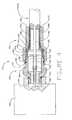
- FIG. 1is a side cutaway view along the centerline of a preferred embodiment of a connector, as disclosed herein, comprising a body subassembly and a back nut subassembly illustrated in the “as shipped” condition ready for installation onto a prepared coaxial cable;
- FIG. 2is a side cutaway view along the centerline of the prepared end of a hardline coaxial cable
- FIG. 3is a side cutaway view along the centerline of a preferred embodiment of a connector, as disclosed herein, comprising a body subassembly and a back nut subassembly illustrated in a partially installed condition;
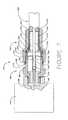
- FIG. 4is a side cutaway view along the centerline of a preferred embodiment of a connector, as disclosed herein, comprising a body subassembly and a back nut subassembly illustrated in a fully installed condition;
- FIG. 5is a side cutaway view along the centerline of a preferred embodiment of a connector, as disclosed herein, comprising a body subassembly and a back nut subassembly illustrated as fully installed and then separated condition;
- FIGS. 6A and 6Bare side cutaway views along the centerline showing optional embodiments of sleeve captivation
- FIG. 7is a side cutaway view along the centerline of optional embodiments of a connector, as disclosed herein, where greater pressure is exerted on the clamping mechanism, forming a localized annular depression in the cable outer conductor and sleeve;
- FIG. 8is a side cutaway view along the centerline of an alternate embodiment of a connector, as disclosed herein, comprising a body subassembly and a back nut subassembly wherein the second end of the body subassembly comprises internal threads and the first end of the back nut subassembly comprises external threads and is illustrated in an uninstalled, separated condition;
- FIG. 9is a side cutaway view along the centerline of yet another alternate embodiment of a connector, as disclosed herein, comprising a body subassembly and a back nut subassembly wherein the body subassembly comprises an alternative method for closing, or activating, the connector center contact mechanism;
- FIG. 10is a side cutaway view along the centerline of yet another alternate embodiment of a connector, as disclosed herein, comprising a body subassembly and a back nut subassembly wherein the body subassembly comprises still another alternative method for closing, or activating, the connector center contact mechanism;
- FIG. 11is a partial side cutaway view along the centerline of a preferred embodiment in an unmated condition of a connector illustrating an anti-rotation feature
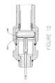
- FIG. 12is a partial side cutaway view along the centerline of a preferred embodiment in a partially mated condition of a connector illustrating an anti-rotation feature.
- connector 100includes a body subassembly 200 and back nut subassembly 300 .
- Body subassembly 200includes body 215 made from electrically conductive material, preferably metal such as aluminum, and has a first end 225 adapted to connect to an equipment port (see FIG. 3 ) and a second end 235 having external threads 240 .
- Body 215is preferably a generally cylindrical, unitary piece and preferably has a outwardly radially extending area 255 with an outer configuration (such as a hex configuration) that allows the body subassembly 200 to be attached to and tightened on an equipment port using a standard tool, such as a wrench.
- Body subassembly 200preferably houses pin 205 made from electrically conductive material, preferably metal, such as tin-plated brass.
- Pin 205has a front end 260 for connecting to an equipment port and a back end 265 , the back end having a socket contact 245 for receiving the center conductor of a coaxial cable.
- Socket contact 245preferably includes a plurality of cantilevered tines 250 .
- Body subassembly 200also preferably houses insulator 210 made from electrically non-conductive material, preferably plastic such as polycarbonate, and actuator 220 made from electrically non-conductive material, preferably plastic such as polyimide thermoplastic resins of, for example, amorphous polyetherimide also known as Ultem®.
- Body subassembly 200may optionally include o-rings 270 and/or 275 .
- Back nut subassembly 300includes back nut 325 made from electrically conductive material, preferably metal such as aluminum, and has a first end 330 having internal threads 340 adapted to mate with external threads 240 and a second end 335 adapted to receive a prepared end of a coaxial cable (see FIG. 3 ).
- the inner surface of back nut 325includes a tapered portion 350 that decreases in diameter from a first diameter D 1 between the tapered portion 350 and the first end 330 of the back nut subassembly 300 to a second diameter D 2 between the tapered portion 350 and the second end 335 of the back nut subassembly 300 .
- Back nut 325is preferably a generally cylindrical, unitary piece and preferably has an outwardly radially extending area 345 with an outer configuration (such as a hex configuration) that allows the back nut subassembly 300 to be attached to and tightened on to body subassembly 200 using a standard tool, such as a wrench.
- Back nut subassembly 300houses deformable ferrule 310 made from electrically conductive and malleable material, preferably metal, such as aluminum or, alternately, tin-plated brass.
- Ferrule 310preferably has an outer diameter that is less than first diameter D 1 and greater than second diameter D 2 .
- Back nut subassembly 300also preferably houses sleeve 315 preferably made from electrically conductive material, preferably metal such as aluminum. Alternatively, sleeve 315 can be made from a plastic material.
- Sleeve 315is preferably a generally cylindrical unitary piece and preferably has an increased diameter front end 355 and a decreased diameter back end 360 wherein the outer diameter of back end 360 is less than second diameter D 2 such that an annular gap 365 extends between outer diameter of back end 360 and second diameter D 2 .
- Outer diameter of back end 360is also preferably less than inner diameter of ferrule 310 such that annular gap 365 also extends between outer diameter of back end 360 and inner diameter of ferrule 310 .
- Back nut subassembly 300may optionally include retaining ring 320 .
- Coaxial cable 1000includes center conductor 1005 made from electrically conductive material, preferably metal such as copper clad aluminum, outer conductor 1010 made from electrically conductive material, preferably metal such as aluminum, and insulative layer 1015 made from electrically non-conductive material, preferably foamed polyethylene plastic.
- center conductor 1005made from electrically conductive material, preferably metal such as copper clad aluminum
- outer conductor 1010made from electrically conductive material, preferably metal such as aluminum
- insulative layer 1015made from electrically non-conductive material, preferably foamed polyethylene plastic.
- FIG. 3illustrates an embodiment where the back nut subassembly 300 is detached from the body subassembly 200 , wherein the first end 225 of the body subassembly 200 has been attached to an equipment port 500 and a prepared end of a coaxial cable 1000 has been inserted into the second end 335 of the back nut subassembly 300 .
- the connector 100is shipped in the configuration shown in FIG. 1 , after which the installer detaches the back nut subassembly 300 from the body subassembly 200 .
- back nut subassemblyhouses sleeve 315 such that outer conductor 1010 of coaxial cable 1000 is inserted in annular gap 365 between back end 360 of sleeve 315 and second diameter D 2 and between back end 360 of sleeve 315 and inner diameter of ferrule 310 .
- the back nut subassembly 300housing the prepared end of coaxial cable 1000 , is ready to be reattached to the body subassembly 200 .
- FIG. 4illustrates connector 100 wherein back nut subassembly 300 has been fully installed and tightened on body subassembly 200 .
- the back nut subassembly 300 including back nut 325is rotatable with respect to both the body subassembly 200 and the coaxial cable 1000 inserted therein.
- tapered portion 350contacts deformable ferrule 310 and causes at least a portion of the ferrule 310 to deform radially inwardly as shown in FIG. 4 .
- Back nut subassembly 300preferably houses sleeve 315 such that as the ferrule deforms radially inwardly against outer conductor 1010 , at least a portion of outer conductor 1010 that is inserted between the outer diameter of back end 360 of sleeve 315 and inner diameter of ferrule 310 is clamped between the sleeve 315 and the ferrule 310 as shown in FIG. 4 . Meanwhile, center conductor 1005 is received in socket contact 245 and, in a preferred embodiment, axial advancement of sleeve 315 toward actuator 220 causes actuator 220 to drive cantilevered tines 250 radially inward against center conductor 1005 .
- FIG. 5shows connector 100 in the re-enterable state wherein back nut subassembly 300 has been detached from body subassembly 200 and body subassembly 200 remains installed in equipment port 500 .
- Back nut subassembly 300is detached from body subassembly 200 by rotating the back nut 325 relative to the coaxial cable 1000 and body subassembly 200 such that the back nut subassembly 300 is advanced axially away from the body subassembly 200 as a result of the mating of the external threads 240 of the body subassembly 200 with the internal threads 340 of the back nut subassembly 300 .
- back nut subassembly 300preferably houses sleeve 315 such that the clamp of at least a portion of outer conductor 1010 between sleeve 315 and ferrule 310 (or at least a portion of the clamped region between sleeve 315 and ferrule 310 ) is maintained upon detachment of the back nut subassembly 300 from the body subassembly 200 .
- back nut 325remains rotatably captivated about cable 1000 and will re-seat against ferrule 310 upon re-installation to body assembly 200 .
- ferrule 310is permanently deformed around outer conductor 1010 and back nut subassembly 300 can be repeatedly attached to and detached from body subassembly 200 while still maintaining electrical and mechanical communication and environmental sealing between ferrule 310 and outer conductor 1010 .
- back nut subassembly 300preferably houses sleeve 315 and back nut subassembly 300 can be repeatedly attached to and detached from body subassembly 200 while still maintaining the clamp of at least a portion of outer conductor 1010 between sleeve 315 and ferrule 310 .
- outer conductor 1010As a result, electrical and mechanical communication is maintained between outer conductor 1010 and both ferrule 310 and sleeve 315 , allowing sleeve to function as a coaxial outer conductor.
- An outer conductor pathcan then be continued via sleeve 315 to body 215 (see, e.g., FIG. 4 showing electrical and mechanical communication between sleeve front end 355 and body 215 ) and therethrough to equipment port 500 .
- FIGS. 6A and 6Billustrate optional back nut captivation methods.
- sleeve 315is axially retained in back nut 325 by means of threading sleeve 315 into back nut 325 until the threaded portion of sleeve 315 has moved beyond the internal thread 340 of back nut 325 in the direction of second end 335 of back nut 325 .
- sleeve 315is captivated within back nut 325 with limited axial and radial movement permitted. Re-engagement of the corresponding threads is difficult and unlikely, thereby rendering sleeve 315 captivated within back nut 325 .
- FIG. 6Ban alternate means of component assembly is illustrated, wherein the parts are not retained in respect to one another and are permitted to move as individual components being placed in juxtaposition only at time of final assembly to cable.
- FIG. 7is a side cutaway view along the centerline of an optional embodiment where greater pressure is exerted on the clamping mechanism, purposely forming outer conductor 1010 and sleeve 315 in a localized annular depression.
- ferrule 310is circumferentially compressed by tapered portion 350 with enough pressure to cause localized annular depressions of both the outer conductor 1010 and the sleeve 315 .
- resistance to Radio Frequency Interference leakagecan be increased by the relatively convoluted path created by the radial deformation and outer conductor retention characteristics can be improved.
- the variance in impedance match caused by the localized annular depressioncan be electrically compensated by incorporating internal step features, or, bores (not shown), in sleeve front end 355 , and can, thereby, render excellent electrical performance characteristics such as improved Return Loss and reduced Radio Frequency Interference (radiation of signal).
- FIG. 8is a side cutaway view along the centerline of an alternate embodiment of a connector, as disclosed herein, comprising body subassembly 200 and back nut subassembly 300 wherein the second end 235 of body subassembly 200 comprises internal threads 240 A and the first end 330 of back nut subassembly 300 comprises external threads 330 A.
- Back nut subassemblyalso optionally includes o-ring 275 A.
- FIG. 9is a side cutaway view along the centerline of yet another alternate embodiment of a connector comprising a body subassembly 200 and back nut subassembly 300 wherein body subassembly 200 comprises an alternative method for closing, or activating, connector center contact mechanism.
- Coaxial cable center conductor 1005is received in socket contact 245 .
- Axial advancement of sleeve 315 toward optional embodiment actuator 220 Acauses actuator 220 A to drive forward within body subassembly 200 .
- Forward movement of actuator 220 Acauses angled portion 220 B of contact 245 to drive cantilevered tines 250 radially inward against center conductor 1005 .
- FIG. 10is a side cutaway view along the centerline of yet another alternate embodiment of a connector comprising a body subassembly 200 and back nut subassembly 300 wherein body subassembly 200 comprises yet an alternative method for closing, or activating, connector center contact mechanism.
- Coaxial cable center conductor 1005is received in socket contact 245 .
- Axial advancement of sleeve 315 toward optional embodiment actuator 220 Bcauses actuator 220 B to drive forward within body subassembly 200 linearly and radially against slotted insulator 210 A.
- Forward movement of actuator 220 Bcauses angled portion of slotted insulator 210 A to, in turn, drive cantilevered tines 250 of contact 245 radially inward against center conductor 1005 .
- FIG. 11is a partial side cutaway view along the centerline of a preferred embodiment of a connector in an unmated condition illustrating an anti-rotation feature (in FIG. 11 , actuator 220 is not shown for clarity).
- Sleeve 315comprises conically knurled portion 380 and body 215 comprises corresponding knurled, embossed or indented portion 280 .
- FIG. 12is a partial side cutaway view along the centerline of the connector of FIG. 11 in a partially mated condition wherein conically knurled portion 380 of sleeve 315 engages indented portion 280 of body 215 similar to male and female splines on a shaft providing resistance to rotative forces applied by back nut 325 , ferrule 310 and cable outer conductor 1010 during tightening.
Landscapes
- Coupling Device And Connection With Printed Circuit (AREA)
Abstract
Description
Claims (19)
Priority Applications (2)
| Application Number | Priority Date | Filing Date | Title |
|---|---|---|---|
| US12/502,633US7972176B2 (en) | 2008-07-23 | 2009-07-14 | Hardline coaxial cable connector |
| US13/175,874US8366482B2 (en) | 2009-07-14 | 2011-07-03 | Re-enterable hardline coaxial cable connector |
Applications Claiming Priority (2)
| Application Number | Priority Date | Filing Date | Title |
|---|---|---|---|
| US8296408P | 2008-07-23 | 2008-07-23 | |
| US12/502,633US7972176B2 (en) | 2008-07-23 | 2009-07-14 | Hardline coaxial cable connector |
Related Child Applications (1)
| Application Number | Title | Priority Date | Filing Date |
|---|---|---|---|
| US13/175,874Continuation-In-PartUS8366482B2 (en) | 2009-07-14 | 2011-07-03 | Re-enterable hardline coaxial cable connector |
Publications (2)
| Publication Number | Publication Date |
|---|---|
| US20100022125A1 US20100022125A1 (en) | 2010-01-28 |
| US7972176B2true US7972176B2 (en) | 2011-07-05 |
Family
ID=41165529
Family Applications (1)
| Application Number | Title | Priority Date | Filing Date |
|---|---|---|---|
| US12/502,633Expired - Fee RelatedUS7972176B2 (en) | 2008-07-23 | 2009-07-14 | Hardline coaxial cable connector |
Country Status (5)
| Country | Link |
|---|---|
| US (1) | US7972176B2 (en) |
| EP (1) | EP2311153A1 (en) |
| CN (1) | CN102132461B (en) |
| TW (1) | TWI412190B (en) |
| WO (1) | WO2010011269A1 (en) |
Cited By (39)
| Publication number | Priority date | Publication date | Assignee | Title |
|---|---|---|---|---|
| US20110138623A1 (en)* | 2008-05-08 | 2011-06-16 | Merical Edward L | Method for attaching a connector to a prepared coaxial cable |
| US20110201232A1 (en)* | 2010-02-16 | 2011-08-18 | Andrew Llc | Connector for coaxial cable having rotational joint between insulator member and center contact and associated methods |
| US20120077368A1 (en)* | 2010-09-23 | 2012-03-29 | Spinner Gmbh | Electric plug-in connector with a union nut |
| US20120171895A1 (en)* | 2009-07-14 | 2012-07-05 | Donald Andrew Burris | Re-Enterable Hardline Coaxial Cable Connector |
| US20140057473A1 (en)* | 2012-08-27 | 2014-02-27 | Changzhou Amphenol Fuyang Communication Equipment Co., Ltd. | Cable connector |
| US20140127941A1 (en)* | 2012-11-08 | 2014-05-08 | Yueh-Chiung Lu | Aluminum tube coaxial cable connector |
| US20140148044A1 (en)* | 2012-11-29 | 2014-05-29 | Anders Balcer | Hardline coaxial connector with a locking ferrule |
| US20140273622A1 (en)* | 2013-03-15 | 2014-09-18 | Fct Electronics Lp | High-Temperature RF Connector |
| US8888526B2 (en) | 2010-08-10 | 2014-11-18 | Corning Gilbert, Inc. | Coaxial cable connector with radio frequency interference and grounding shield |
| US9048599B2 (en) | 2013-10-28 | 2015-06-02 | Corning Gilbert Inc. | Coaxial cable connector having a gripping member with a notch and disposed inside a shell |
| US9052469B2 (en) | 2013-04-26 | 2015-06-09 | Corning Cable Systems Llc | Preterminated fiber optic connector sub-assemblies, and related fiber optic connectors, cable assemblies, and methods |
| US9071019B2 (en) | 2010-10-27 | 2015-06-30 | Corning Gilbert, Inc. | Push-on cable connector with a coupler and retention and release mechanism |
| US20150207243A1 (en)* | 2014-01-21 | 2015-07-23 | Ppc Broadband, Inc. | Cable connector structured for reassembly and method thereof |
| US9136654B2 (en) | 2012-01-05 | 2015-09-15 | Corning Gilbert, Inc. | Quick mount connector for a coaxial cable |
| US9153911B2 (en) | 2013-02-19 | 2015-10-06 | Corning Gilbert Inc. | Coaxial cable continuity connector |
| US9166348B2 (en) | 2010-04-13 | 2015-10-20 | Corning Gilbert Inc. | Coaxial connector with inhibited ingress and improved grounding |
| US9172154B2 (en) | 2013-03-15 | 2015-10-27 | Corning Gilbert Inc. | Coaxial cable connector with integral RFI protection |
| US9190744B2 (en) | 2011-09-14 | 2015-11-17 | Corning Optical Communications Rf Llc | Coaxial cable connector with radio frequency interference and grounding shield |
| US9287659B2 (en) | 2012-10-16 | 2016-03-15 | Corning Optical Communications Rf Llc | Coaxial cable connector with integral RFI protection |
| US9407016B2 (en) | 2012-02-22 | 2016-08-02 | Corning Optical Communications Rf Llc | Coaxial cable connector with integral continuity contacting portion |
| US9525220B1 (en) | 2015-11-25 | 2016-12-20 | Corning Optical Communications LLC | Coaxial cable connector |
| US9531180B2 (en) | 2013-12-11 | 2016-12-27 | Changzhou Amphenol Fuyang Communication Equip. Co., Ltd. | Waterproof cable assembly/connector |
| US9548557B2 (en) | 2013-06-26 | 2017-01-17 | Corning Optical Communications LLC | Connector assemblies and methods of manufacture |
| US9548572B2 (en) | 2014-11-03 | 2017-01-17 | Corning Optical Communications LLC | Coaxial cable connector having a coupler and a post with a contacting portion and a shoulder |
| US9590287B2 (en) | 2015-02-20 | 2017-03-07 | Corning Optical Communications Rf Llc | Surge protected coaxial termination |
| US9739961B2 (en)* | 2015-03-31 | 2017-08-22 | Avago Technologies General Ip (Singapore) Pte. Ltd. | Pluggable optical communications module and system with aligned ESA axis |
| US9762008B2 (en) | 2013-05-20 | 2017-09-12 | Corning Optical Communications Rf Llc | Coaxial cable connector with integral RFI protection |
| US9859631B2 (en) | 2011-09-15 | 2018-01-02 | Corning Optical Communications Rf Llc | Coaxial cable connector with integral radio frequency interference and grounding shield |
| US9979101B2 (en)* | 2015-03-12 | 2018-05-22 | Nokia Shanghai Bell | Corrosion protected communication connections and related methods |
| US10033122B2 (en) | 2015-02-20 | 2018-07-24 | Corning Optical Communications Rf Llc | Cable or conduit connector with jacket retention feature |
| US20180323537A1 (en)* | 2016-01-22 | 2018-11-08 | Yaowu Ma | Secure electrical socket and plug |
| US10211547B2 (en) | 2015-09-03 | 2019-02-19 | Corning Optical Communications Rf Llc | Coaxial cable connector |
| US10290958B2 (en) | 2013-04-29 | 2019-05-14 | Corning Optical Communications Rf Llc | Coaxial cable connector with integral RFI protection and biasing ring |
| US10396474B2 (en) | 2015-11-19 | 2019-08-27 | Corning Optical Communications Rf Llc | Coaxial cable connector |
| US10756455B2 (en) | 2005-01-25 | 2020-08-25 | Corning Optical Communications Rf Llc | Electrical connector with grounding member |
| US20220209476A1 (en)* | 2020-12-31 | 2022-06-30 | Ppc Broadband, Inc. | Heat dissipating connectors |
| US12034264B2 (en) | 2021-03-31 | 2024-07-09 | Corning Optical Communications Rf Llc | Coaxial cable connector assemblies with outer conductor engagement features and methods for using the same |
| US12249798B2 (en) | 2020-01-03 | 2025-03-11 | Commscope Technologies Llc | Non-shorting cable coring tool |
| WO2025145217A1 (en)* | 2023-12-29 | 2025-07-03 | Ppc Broadband, Inc. | Hardline connector having a metal-reinforced plastic mandrel portion structurally configured to prevent mandrel portion deformation |
Families Citing this family (23)
| Publication number | Priority date | Publication date | Assignee | Title |
|---|---|---|---|---|
| US7909614B1 (en)* | 2009-12-01 | 2011-03-22 | Ezconn Corporation | Anti-rotation connector for shielding structure |
| US8454385B2 (en) | 2010-06-22 | 2013-06-04 | John Mezzalingua Associates, LLC | Coaxial cable connector with strain relief clamp |
| US8430687B2 (en)* | 2011-04-01 | 2013-04-30 | Ppc Broadband, Inc. | Method and apparatus for a snap retained push-on connector with port adapter |
| BR112014004217A2 (en)* | 2011-09-20 | 2017-03-21 | Cabletech Cabos Ltda | quick coupler connector |
| CN102916273A (en)* | 2012-10-25 | 2013-02-06 | 成都四威高科技产业园有限公司 | High-precision radio-frequency coaxial connector structure |
| US8986044B2 (en)* | 2012-10-26 | 2015-03-24 | Corning Gilbert Inc. | Quick mount connector for a coaxial cable |
| TWI625903B (en)* | 2012-11-20 | 2018-06-01 | 康寧吉伯特公司 | Hardline coaxial connector with a locking ferrule |
| US9702680B2 (en) | 2013-07-18 | 2017-07-11 | Dynaenergetics Gmbh & Co. Kg | Perforation gun components and system |
| US9784549B2 (en)* | 2015-03-18 | 2017-10-10 | Dynaenergetics Gmbh & Co. Kg | Bulkhead assembly having a pivotable electric contact component and integrated ground apparatus |
| US11293736B2 (en)* | 2015-03-18 | 2022-04-05 | DynaEnergetics Europe GmbH | Electrical connector |
| WO2017079152A1 (en)* | 2015-11-05 | 2017-05-11 | Commscope Technologies Llc | Easily assembled coaxial cable and connector with rear body |
| USD903064S1 (en) | 2020-03-31 | 2020-11-24 | DynaEnergetics Europe GmbH | Alignment sub |
| US11339614B2 (en) | 2020-03-31 | 2022-05-24 | DynaEnergetics Europe GmbH | Alignment sub and orienting sub adapter |
| CH717156A2 (en)* | 2020-02-20 | 2021-08-31 | Agro Ag | Holding device for holding a cable. |
| US11988049B2 (en) | 2020-03-31 | 2024-05-21 | DynaEnergetics Europe GmbH | Alignment sub and perforating gun assembly with alignment sub |
| NO20230794A1 (en) | 2020-12-21 | 2023-07-17 | DynaEnergetics Europe GmbH | Encapsulated shaped charge |
| WO2022148557A1 (en) | 2021-01-08 | 2022-07-14 | DynaEnergetics Europe GmbH | Perforating gun assembly and components |
| WO2022184732A1 (en) | 2021-03-03 | 2022-09-09 | DynaEnergetics Europe GmbH | Bulkhead and tandem seal adapter |
| US11713625B2 (en) | 2021-03-03 | 2023-08-01 | DynaEnergetics Europe GmbH | Bulkhead |
| US12366142B2 (en) | 2021-03-03 | 2025-07-22 | DynaEnergetics Europe GmbH | Modular perforating gun system |
| US12000267B2 (en) | 2021-09-24 | 2024-06-04 | DynaEnergetics Europe GmbH | Communication and location system for an autonomous frack system |
| US12253339B2 (en) | 2021-10-25 | 2025-03-18 | DynaEnergetics Europe GmbH | Adapter and shaped charge apparatus for optimized perforation jet |
| US12312925B2 (en) | 2021-12-22 | 2025-05-27 | DynaEnergetics Europe GmbH | Manually oriented internal shaped charge alignment system and method of use |
Citations (9)
| Publication number | Priority date | Publication date | Assignee | Title |
|---|---|---|---|---|
| US3537065A (en)* | 1967-01-12 | 1970-10-27 | Jerrold Electronics Corp | Multiferrule cable connector |
| US4575274A (en)* | 1983-03-02 | 1986-03-11 | Gilbert Engineering Company Inc. | Controlled torque connector assembly |
| US4854893A (en)* | 1987-11-30 | 1989-08-08 | Pyramid Industries, Inc. | Coaxial cable connector and method of terminating a cable using same |
| US4923412A (en) | 1987-11-30 | 1990-05-08 | Pyramid Industries, Inc. | Terminal end for coaxial cable |
| US20030135999A1 (en) | 2002-01-18 | 2003-07-24 | Khemakhem M?Apos;Hamed Anis | Triaxial connector including cable clamp |
| US20040142596A1 (en) | 2003-01-16 | 2004-07-22 | Jimmy Henningsen | Coaxial cable connector |
| US6808415B1 (en) | 2004-01-26 | 2004-10-26 | John Mezzalingua Associates, Inc. | Clamping and sealing mechanism with multiple rings for cable connector |
| US6884113B1 (en) | 2003-10-15 | 2005-04-26 | John Mezzalingua Associates, Inc. | Apparatus for making permanent hardline connection |
| US20070155233A1 (en) | 2005-12-29 | 2007-07-05 | Laerke Per R | Coaxial cable connector with collapsible insert |
Family Cites Families (1)
| Publication number | Priority date | Publication date | Assignee | Title |
|---|---|---|---|---|
| US7029304B2 (en)* | 2004-02-04 | 2006-04-18 | John Mezzalingua Associates, Inc. | Compression connector with integral coupler |
- 2009
- 2009-07-14USUS12/502,633patent/US7972176B2/ennot_activeExpired - Fee Related
- 2009-07-16WOPCT/US2009/004127patent/WO2010011269A1/enactiveApplication Filing
- 2009-07-16EPEP09788930Apatent/EP2311153A1/ennot_activeWithdrawn
- 2009-07-16CNCN2009801338262Apatent/CN102132461B/ennot_activeExpired - Fee Related
- 2009-07-20TWTW098124499Apatent/TWI412190B/ennot_activeIP Right Cessation
Patent Citations (9)
| Publication number | Priority date | Publication date | Assignee | Title |
|---|---|---|---|---|
| US3537065A (en)* | 1967-01-12 | 1970-10-27 | Jerrold Electronics Corp | Multiferrule cable connector |
| US4575274A (en)* | 1983-03-02 | 1986-03-11 | Gilbert Engineering Company Inc. | Controlled torque connector assembly |
| US4854893A (en)* | 1987-11-30 | 1989-08-08 | Pyramid Industries, Inc. | Coaxial cable connector and method of terminating a cable using same |
| US4923412A (en) | 1987-11-30 | 1990-05-08 | Pyramid Industries, Inc. | Terminal end for coaxial cable |
| US20030135999A1 (en) | 2002-01-18 | 2003-07-24 | Khemakhem M?Apos;Hamed Anis | Triaxial connector including cable clamp |
| US20040142596A1 (en) | 2003-01-16 | 2004-07-22 | Jimmy Henningsen | Coaxial cable connector |
| US6884113B1 (en) | 2003-10-15 | 2005-04-26 | John Mezzalingua Associates, Inc. | Apparatus for making permanent hardline connection |
| US6808415B1 (en) | 2004-01-26 | 2004-10-26 | John Mezzalingua Associates, Inc. | Clamping and sealing mechanism with multiple rings for cable connector |
| US20070155233A1 (en) | 2005-12-29 | 2007-07-05 | Laerke Per R | Coaxial cable connector with collapsible insert |
Cited By (60)
| Publication number | Priority date | Publication date | Assignee | Title |
|---|---|---|---|---|
| US10756455B2 (en) | 2005-01-25 | 2020-08-25 | Corning Optical Communications Rf Llc | Electrical connector with grounding member |
| US8701278B2 (en)* | 2008-05-08 | 2014-04-22 | Pds Electronics, Inc. | Method for attaching a connector to a prepared coaxial cable |
| US20110138623A1 (en)* | 2008-05-08 | 2011-06-16 | Merical Edward L | Method for attaching a connector to a prepared coaxial cable |
| US9614341B2 (en) | 2008-05-08 | 2017-04-04 | Pds Electronics, Inc. | Device for attaching a connector to a prepared coaxial cable |
| US20120171895A1 (en)* | 2009-07-14 | 2012-07-05 | Donald Andrew Burris | Re-Enterable Hardline Coaxial Cable Connector |
| US8366482B2 (en)* | 2009-07-14 | 2013-02-05 | Corning Gilbert Inc. | Re-enterable hardline coaxial cable connector |
| US20110201232A1 (en)* | 2010-02-16 | 2011-08-18 | Andrew Llc | Connector for coaxial cable having rotational joint between insulator member and center contact and associated methods |
| US9166348B2 (en) | 2010-04-13 | 2015-10-20 | Corning Gilbert Inc. | Coaxial connector with inhibited ingress and improved grounding |
| US9905959B2 (en) | 2010-04-13 | 2018-02-27 | Corning Optical Communication RF LLC | Coaxial connector with inhibited ingress and improved grounding |
| US10312629B2 (en) | 2010-04-13 | 2019-06-04 | Corning Optical Communications Rf Llc | Coaxial connector with inhibited ingress and improved grounding |
| US8888526B2 (en) | 2010-08-10 | 2014-11-18 | Corning Gilbert, Inc. | Coaxial cable connector with radio frequency interference and grounding shield |
| US20120077368A1 (en)* | 2010-09-23 | 2012-03-29 | Spinner Gmbh | Electric plug-in connector with a union nut |
| US8408938B2 (en)* | 2010-09-23 | 2013-04-02 | Spinner Gmbh | Electric plug-in connector with a union nut |
| US9071019B2 (en) | 2010-10-27 | 2015-06-30 | Corning Gilbert, Inc. | Push-on cable connector with a coupler and retention and release mechanism |
| US9190744B2 (en) | 2011-09-14 | 2015-11-17 | Corning Optical Communications Rf Llc | Coaxial cable connector with radio frequency interference and grounding shield |
| US9859631B2 (en) | 2011-09-15 | 2018-01-02 | Corning Optical Communications Rf Llc | Coaxial cable connector with integral radio frequency interference and grounding shield |
| US9768565B2 (en) | 2012-01-05 | 2017-09-19 | Corning Optical Communications Rf Llc | Quick mount connector for a coaxial cable |
| US9136654B2 (en) | 2012-01-05 | 2015-09-15 | Corning Gilbert, Inc. | Quick mount connector for a coaxial cable |
| US9484645B2 (en) | 2012-01-05 | 2016-11-01 | Corning Optical Communications Rf Llc | Quick mount connector for a coaxial cable |
| US9407016B2 (en) | 2012-02-22 | 2016-08-02 | Corning Optical Communications Rf Llc | Coaxial cable connector with integral continuity contacting portion |
| US20140057473A1 (en)* | 2012-08-27 | 2014-02-27 | Changzhou Amphenol Fuyang Communication Equipment Co., Ltd. | Cable connector |
| US9722363B2 (en) | 2012-10-16 | 2017-08-01 | Corning Optical Communications Rf Llc | Coaxial cable connector with integral RFI protection |
| US9912105B2 (en) | 2012-10-16 | 2018-03-06 | Corning Optical Communications Rf Llc | Coaxial cable connector with integral RFI protection |
| US10236636B2 (en) | 2012-10-16 | 2019-03-19 | Corning Optical Communications Rf Llc | Coaxial cable connector with integral RFI protection |
| US9287659B2 (en) | 2012-10-16 | 2016-03-15 | Corning Optical Communications Rf Llc | Coaxial cable connector with integral RFI protection |
| US20140127941A1 (en)* | 2012-11-08 | 2014-05-08 | Yueh-Chiung Lu | Aluminum tube coaxial cable connector |
| US8876553B2 (en)* | 2012-11-08 | 2014-11-04 | Yueh-Chiung Lu | Aluminum tube coaxial cable connector |
| US9147963B2 (en)* | 2012-11-29 | 2015-09-29 | Corning Gilbert Inc. | Hardline coaxial connector with a locking ferrule |
| US20140148044A1 (en)* | 2012-11-29 | 2014-05-29 | Anders Balcer | Hardline coaxial connector with a locking ferrule |
| US9153911B2 (en) | 2013-02-19 | 2015-10-06 | Corning Gilbert Inc. | Coaxial cable continuity connector |
| US9276332B2 (en)* | 2013-03-15 | 2016-03-01 | Fct, Us L.L.C. | High-temperature RF connector |
| US9172154B2 (en) | 2013-03-15 | 2015-10-27 | Corning Gilbert Inc. | Coaxial cable connector with integral RFI protection |
| US20140273622A1 (en)* | 2013-03-15 | 2014-09-18 | Fct Electronics Lp | High-Temperature RF Connector |
| US9151905B2 (en) | 2013-04-26 | 2015-10-06 | Corning Optical Communications LLC | Preterminated fiber optic connector sub-assemblies, and related fiber optic connectors, cable assemblies, and methods |
| US9052469B2 (en) | 2013-04-26 | 2015-06-09 | Corning Cable Systems Llc | Preterminated fiber optic connector sub-assemblies, and related fiber optic connectors, cable assemblies, and methods |
| US10290958B2 (en) | 2013-04-29 | 2019-05-14 | Corning Optical Communications Rf Llc | Coaxial cable connector with integral RFI protection and biasing ring |
| US10396508B2 (en) | 2013-05-20 | 2019-08-27 | Corning Optical Communications Rf Llc | Coaxial cable connector with integral RFI protection |
| US9762008B2 (en) | 2013-05-20 | 2017-09-12 | Corning Optical Communications Rf Llc | Coaxial cable connector with integral RFI protection |
| US9548557B2 (en) | 2013-06-26 | 2017-01-17 | Corning Optical Communications LLC | Connector assemblies and methods of manufacture |
| US9048599B2 (en) | 2013-10-28 | 2015-06-02 | Corning Gilbert Inc. | Coaxial cable connector having a gripping member with a notch and disposed inside a shell |
| US9531180B2 (en) | 2013-12-11 | 2016-12-27 | Changzhou Amphenol Fuyang Communication Equip. Co., Ltd. | Waterproof cable assembly/connector |
| US9484646B2 (en)* | 2014-01-21 | 2016-11-01 | Ppc Broadband, Inc. | Cable connector structured for reassembly and method thereof |
| US20150207243A1 (en)* | 2014-01-21 | 2015-07-23 | Ppc Broadband, Inc. | Cable connector structured for reassembly and method thereof |
| US9548572B2 (en) | 2014-11-03 | 2017-01-17 | Corning Optical Communications LLC | Coaxial cable connector having a coupler and a post with a contacting portion and a shoulder |
| US9991651B2 (en) | 2014-11-03 | 2018-06-05 | Corning Optical Communications Rf Llc | Coaxial cable connector with post including radially expanding tabs |
| US9590287B2 (en) | 2015-02-20 | 2017-03-07 | Corning Optical Communications Rf Llc | Surge protected coaxial termination |
| US10033122B2 (en) | 2015-02-20 | 2018-07-24 | Corning Optical Communications Rf Llc | Cable or conduit connector with jacket retention feature |
| US9979101B2 (en)* | 2015-03-12 | 2018-05-22 | Nokia Shanghai Bell | Corrosion protected communication connections and related methods |
| US9739961B2 (en)* | 2015-03-31 | 2017-08-22 | Avago Technologies General Ip (Singapore) Pte. Ltd. | Pluggable optical communications module and system with aligned ESA axis |
| US10211547B2 (en) | 2015-09-03 | 2019-02-19 | Corning Optical Communications Rf Llc | Coaxial cable connector |
| US10396474B2 (en) | 2015-11-19 | 2019-08-27 | Corning Optical Communications Rf Llc | Coaxial cable connector |
| US9882320B2 (en) | 2015-11-25 | 2018-01-30 | Corning Optical Communications Rf Llc | Coaxial cable connector |
| US9525220B1 (en) | 2015-11-25 | 2016-12-20 | Corning Optical Communications LLC | Coaxial cable connector |
| US20180323537A1 (en)* | 2016-01-22 | 2018-11-08 | Yaowu Ma | Secure electrical socket and plug |
| US10797436B2 (en)* | 2016-01-22 | 2020-10-06 | Yaowu Ma | Electrical connector structure adapted for a cigarette lighting device in vehicles |
| US12249798B2 (en) | 2020-01-03 | 2025-03-11 | Commscope Technologies Llc | Non-shorting cable coring tool |
| US20220209476A1 (en)* | 2020-12-31 | 2022-06-30 | Ppc Broadband, Inc. | Heat dissipating connectors |
| US11962114B2 (en)* | 2020-12-31 | 2024-04-16 | Ppc Broadband, Inc. | Heat dissipating connectors |
| US12034264B2 (en) | 2021-03-31 | 2024-07-09 | Corning Optical Communications Rf Llc | Coaxial cable connector assemblies with outer conductor engagement features and methods for using the same |
| WO2025145217A1 (en)* | 2023-12-29 | 2025-07-03 | Ppc Broadband, Inc. | Hardline connector having a metal-reinforced plastic mandrel portion structurally configured to prevent mandrel portion deformation |
Also Published As
| Publication number | Publication date |
|---|---|
| WO2010011269A1 (en) | 2010-01-28 |
| EP2311153A1 (en) | 2011-04-20 |
| TWI412190B (en) | 2013-10-11 |
| CN102132461B (en) | 2013-11-20 |
| CN102132461A (en) | 2011-07-20 |
| US20100022125A1 (en) | 2010-01-28 |
| TW201021325A (en) | 2010-06-01 |
Similar Documents
| Publication | Publication Date | Title |
|---|---|---|
| US7972176B2 (en) | Hardline coaxial cable connector | |
| US8366482B2 (en) | Re-enterable hardline coaxial cable connector | |
| US8075337B2 (en) | Cable connector | |
| US10833432B2 (en) | Easily assembled coaxial cable and connector with rear body | |
| US7404737B1 (en) | Coaxial cable connector | |
| EP2041843B1 (en) | Coaxial connector and method | |
| US7182639B2 (en) | Coaxial cable connector | |
| US7018235B1 (en) | Coaxial cable connector | |
| EP3329554B1 (en) | Cable connector | |
| US8292661B2 (en) | Phone plug connector device | |
| US8303339B2 (en) | Audio jack connector device | |
| US7160149B1 (en) | Coaxial connector and method of connecting a two-wire cable to a coaxial connector | |
| US11125810B2 (en) | Blind-mate PIM testing adapter connector and fixture | |
| US20090004906A1 (en) | Electrical Connector Having Cam Locking Features | |
| CN100502149C (en) | A coaxial cable connector | |
| US20020193007A1 (en) | Broadband coaxial microwave connector | |
| CA2681200C (en) | Cable connector |
Legal Events
| Date | Code | Title | Description |
|---|---|---|---|
| AS | Assignment | Owner name:CORNING GILBERT INC., ARIZONA Free format text:ASSIGNMENT OF ASSIGNORS INTEREST;ASSIGNORS:BURRIS, DONALD ANDREW;LUTZ, WILLIAM BERNARD;REEL/FRAME:022953/0981 Effective date:20090615 | |
| STCF | Information on status: patent grant | Free format text:PATENTED CASE | |
| FPAY | Fee payment | Year of fee payment:4 | |
| AS | Assignment | Owner name:CORNING OPTICAL COMMUNICATIONS RF LLC, ARIZONA Free format text:CHANGE OF NAME;ASSIGNOR:CORNING GILBERT, INC.;REEL/FRAME:036687/0562 Effective date:20140122 | |
| FEPP | Fee payment procedure | Free format text:MAINTENANCE FEE REMINDER MAILED (ORIGINAL EVENT CODE: REM.); ENTITY STATUS OF PATENT OWNER: LARGE ENTITY | |
| LAPS | Lapse for failure to pay maintenance fees | Free format text:PATENT EXPIRED FOR FAILURE TO PAY MAINTENANCE FEES (ORIGINAL EVENT CODE: EXP.); ENTITY STATUS OF PATENT OWNER: LARGE ENTITY | |
| STCH | Information on status: patent discontinuation | Free format text:PATENT EXPIRED DUE TO NONPAYMENT OF MAINTENANCE FEES UNDER 37 CFR 1.362 | |
| FP | Lapsed due to failure to pay maintenance fee | Effective date:20190705 | |
| AS | Assignment | Owner name:CORNING OPTICAL COMMUNICATIONS RF LLC, ARIZONA Free format text:CORRECTIVE ASSIGNMENT TO CORRECT THE PROPERTY LISTED IN THE ORIGINAL COVER SHEET PREVIOUSLY RECORDED AT REEL: 036687 FRAME: 0562. ASSIGNOR(S) HEREBY CONFIRMS THE ASSIGNMENT;ASSIGNOR:CORNING GILBERT, INC.;REEL/FRAME:058300/0843 Effective date:20140122 |