US7972167B2 - Electrical connector with a flexible blade-shaped housing with a handle with an opening - Google Patents
Electrical connector with a flexible blade-shaped housing with a handle with an openingDownload PDFInfo
- Publication number
- US7972167B2 US7972167B2US12/559,462US55946209AUS7972167B2US 7972167 B2US7972167 B2US 7972167B2US 55946209 AUS55946209 AUS 55946209AUS 7972167 B2US7972167 B2US 7972167B2
- Authority
- US
- United States
- Prior art keywords
- electrical connector
- housing
- blade
- flexible electrical
- shaped housing
- Prior art date
- Legal status (The legal status is an assumption and is not a legal conclusion. Google has not performed a legal analysis and makes no representation as to the accuracy of the status listed.)
- Active - Reinstated
Links
- 239000000463materialSubstances0.000claimsabstractdescription12
- 230000007246mechanismEffects0.000claimsdescription23
- 239000012858resilient materialSubstances0.000claimsdescription10
- 229910052751metalInorganic materials0.000claimsdescription6
- 239000002184metalSubstances0.000claimsdescription6
- 238000005452bendingMethods0.000description7
- 239000000446fuelSubstances0.000description6
- 239000004033plasticSubstances0.000description5
- 230000005540biological transmissionEffects0.000description4
- 239000002803fossil fuelSubstances0.000description4
- 239000002551biofuelSubstances0.000description2
- 238000002485combustion reactionMethods0.000description2
- 230000000881depressing effectEffects0.000description2
- 230000000994depressogenic effectEffects0.000description2
- 238000005516engineering processMethods0.000description2
- 238000012986modificationMethods0.000description2
- 230000004048modificationEffects0.000description2
- JOYRKODLDBILNP-UHFFFAOYSA-NEthyl urethaneChemical compoundCCOC(N)=OJOYRKODLDBILNP-UHFFFAOYSA-N0.000description1
- HBBGRARXTFLTSG-UHFFFAOYSA-NLithium ionChemical compound[Li+]HBBGRARXTFLTSG-UHFFFAOYSA-N0.000description1
- 239000002253acidSubstances0.000description1
- 239000003990capacitorSubstances0.000description1
- 238000006243chemical reactionMethods0.000description1
- 230000006835compressionEffects0.000description1
- 238000007906compressionMethods0.000description1
- 230000007423decreaseEffects0.000description1
- 238000003780insertionMethods0.000description1
- 230000037431insertionEffects0.000description1
- 229910001416lithium ionInorganic materials0.000description1
- 230000013011matingEffects0.000description1
- 229910052987metal hydrideInorganic materials0.000description1
- 238000000034methodMethods0.000description1
- 238000000465mouldingMethods0.000description1
- 229920000642polymerPolymers0.000description1
- 239000000126substanceSubstances0.000description1
Images


Classifications
- H—ELECTRICITY
- H01—ELECTRIC ELEMENTS
- H01R—ELECTRICALLY-CONDUCTIVE CONNECTIONS; STRUCTURAL ASSOCIATIONS OF A PLURALITY OF MUTUALLY-INSULATED ELECTRICAL CONNECTING ELEMENTS; COUPLING DEVICES; CURRENT COLLECTORS
- H01R31/00—Coupling parts supported only by co-operation with counterpart
- H01R31/06—Intermediate parts for linking two coupling parts, e.g. adapter
- B—PERFORMING OPERATIONS; TRANSPORTING
- B60—VEHICLES IN GENERAL
- B60L—PROPULSION OF ELECTRICALLY-PROPELLED VEHICLES; SUPPLYING ELECTRIC POWER FOR AUXILIARY EQUIPMENT OF ELECTRICALLY-PROPELLED VEHICLES; ELECTRODYNAMIC BRAKE SYSTEMS FOR VEHICLES IN GENERAL; MAGNETIC SUSPENSION OR LEVITATION FOR VEHICLES; MONITORING OPERATING VARIABLES OF ELECTRICALLY-PROPELLED VEHICLES; ELECTRIC SAFETY DEVICES FOR ELECTRICALLY-PROPELLED VEHICLES
- B60L50/00—Electric propulsion with power supplied within the vehicle
- B60L50/40—Electric propulsion with power supplied within the vehicle using propulsion power supplied by capacitors
- B—PERFORMING OPERATIONS; TRANSPORTING
- B60—VEHICLES IN GENERAL
- B60L—PROPULSION OF ELECTRICALLY-PROPELLED VEHICLES; SUPPLYING ELECTRIC POWER FOR AUXILIARY EQUIPMENT OF ELECTRICALLY-PROPELLED VEHICLES; ELECTRODYNAMIC BRAKE SYSTEMS FOR VEHICLES IN GENERAL; MAGNETIC SUSPENSION OR LEVITATION FOR VEHICLES; MONITORING OPERATING VARIABLES OF ELECTRICALLY-PROPELLED VEHICLES; ELECTRIC SAFETY DEVICES FOR ELECTRICALLY-PROPELLED VEHICLES
- B60L53/00—Methods of charging batteries, specially adapted for electric vehicles; Charging stations or on-board charging equipment therefor; Exchange of energy storage elements in electric vehicles
- B60L53/10—Methods of charging batteries, specially adapted for electric vehicles; Charging stations or on-board charging equipment therefor; Exchange of energy storage elements in electric vehicles characterised by the energy transfer between the charging station and the vehicle
- B60L53/14—Conductive energy transfer
- B60L53/16—Connectors, e.g. plugs or sockets, specially adapted for charging electric vehicles
- B—PERFORMING OPERATIONS; TRANSPORTING
- B60—VEHICLES IN GENERAL
- B60L—PROPULSION OF ELECTRICALLY-PROPELLED VEHICLES; SUPPLYING ELECTRIC POWER FOR AUXILIARY EQUIPMENT OF ELECTRICALLY-PROPELLED VEHICLES; ELECTRODYNAMIC BRAKE SYSTEMS FOR VEHICLES IN GENERAL; MAGNETIC SUSPENSION OR LEVITATION FOR VEHICLES; MONITORING OPERATING VARIABLES OF ELECTRICALLY-PROPELLED VEHICLES; ELECTRIC SAFETY DEVICES FOR ELECTRICALLY-PROPELLED VEHICLES
- B60L53/00—Methods of charging batteries, specially adapted for electric vehicles; Charging stations or on-board charging equipment therefor; Exchange of energy storage elements in electric vehicles
- B60L53/10—Methods of charging batteries, specially adapted for electric vehicles; Charging stations or on-board charging equipment therefor; Exchange of energy storage elements in electric vehicles characterised by the energy transfer between the charging station and the vehicle
- B60L53/14—Conductive energy transfer
- B60L53/18—Cables specially adapted for charging electric vehicles
- H—ELECTRICITY
- H01—ELECTRIC ELEMENTS
- H01R—ELECTRICALLY-CONDUCTIVE CONNECTIONS; STRUCTURAL ASSOCIATIONS OF A PLURALITY OF MUTUALLY-INSULATED ELECTRICAL CONNECTING ELEMENTS; COUPLING DEVICES; CURRENT COLLECTORS
- H01R13/00—Details of coupling devices of the kinds covered by groups H01R12/70 or H01R24/00 - H01R33/00
- H01R13/58—Means for relieving strain on wire connection, e.g. cord grip, for avoiding loosening of connections between wires and terminals within a coupling device terminating a cable
- H01R13/582—Means for relieving strain on wire connection, e.g. cord grip, for avoiding loosening of connections between wires and terminals within a coupling device terminating a cable the cable being clamped between assembled parts of the housing
- H01R13/5829—Means for relieving strain on wire connection, e.g. cord grip, for avoiding loosening of connections between wires and terminals within a coupling device terminating a cable the cable being clamped between assembled parts of the housing the clamping part being flexibly or hingedly connected to the housing
- B—PERFORMING OPERATIONS; TRANSPORTING
- B60—VEHICLES IN GENERAL
- B60L—PROPULSION OF ELECTRICALLY-PROPELLED VEHICLES; SUPPLYING ELECTRIC POWER FOR AUXILIARY EQUIPMENT OF ELECTRICALLY-PROPELLED VEHICLES; ELECTRODYNAMIC BRAKE SYSTEMS FOR VEHICLES IN GENERAL; MAGNETIC SUSPENSION OR LEVITATION FOR VEHICLES; MONITORING OPERATING VARIABLES OF ELECTRICALLY-PROPELLED VEHICLES; ELECTRIC SAFETY DEVICES FOR ELECTRICALLY-PROPELLED VEHICLES
- B60L2270/00—Problem solutions or means not otherwise provided for
- B60L2270/30—Preventing theft during charging
- B60L2270/32—Preventing theft during charging of electricity
- B—PERFORMING OPERATIONS; TRANSPORTING
- B60—VEHICLES IN GENERAL
- B60L—PROPULSION OF ELECTRICALLY-PROPELLED VEHICLES; SUPPLYING ELECTRIC POWER FOR AUXILIARY EQUIPMENT OF ELECTRICALLY-PROPELLED VEHICLES; ELECTRODYNAMIC BRAKE SYSTEMS FOR VEHICLES IN GENERAL; MAGNETIC SUSPENSION OR LEVITATION FOR VEHICLES; MONITORING OPERATING VARIABLES OF ELECTRICALLY-PROPELLED VEHICLES; ELECTRIC SAFETY DEVICES FOR ELECTRICALLY-PROPELLED VEHICLES
- B60L2270/00—Problem solutions or means not otherwise provided for
- B60L2270/30—Preventing theft during charging
- B60L2270/34—Preventing theft during charging of parts
- H—ELECTRICITY
- H01—ELECTRIC ELEMENTS
- H01R—ELECTRICALLY-CONDUCTIVE CONNECTIONS; STRUCTURAL ASSOCIATIONS OF A PLURALITY OF MUTUALLY-INSULATED ELECTRICAL CONNECTING ELEMENTS; COUPLING DEVICES; CURRENT COLLECTORS
- H01R12/00—Structural associations of a plurality of mutually-insulated electrical connecting elements, specially adapted for printed circuits, e.g. printed circuit boards [PCB], flat or ribbon cables, or like generally planar structures, e.g. terminal strips, terminal blocks; Coupling devices specially adapted for printed circuits, flat or ribbon cables, or like generally planar structures; Terminals specially adapted for contact with, or insertion into, printed circuits, flat or ribbon cables, or like generally planar structures
- H01R12/50—Fixed connections
- H01R12/59—Fixed connections for flexible printed circuits, flat or ribbon cables or like structures
- H—ELECTRICITY
- H01—ELECTRIC ELEMENTS
- H01R—ELECTRICALLY-CONDUCTIVE CONNECTIONS; STRUCTURAL ASSOCIATIONS OF A PLURALITY OF MUTUALLY-INSULATED ELECTRICAL CONNECTING ELEMENTS; COUPLING DEVICES; CURRENT COLLECTORS
- H01R13/00—Details of coupling devices of the kinds covered by groups H01R12/70 or H01R24/00 - H01R33/00
- H01R13/60—Means for supporting coupling part when not engaged
- H—ELECTRICITY
- H01—ELECTRIC ELEMENTS
- H01R—ELECTRICALLY-CONDUCTIVE CONNECTIONS; STRUCTURAL ASSOCIATIONS OF A PLURALITY OF MUTUALLY-INSULATED ELECTRICAL CONNECTING ELEMENTS; COUPLING DEVICES; CURRENT COLLECTORS
- H01R13/00—Details of coupling devices of the kinds covered by groups H01R12/70 or H01R24/00 - H01R33/00
- H01R13/62—Means for facilitating engagement or disengagement of coupling parts or for holding them in engagement
- H01R13/627—Snap or like fastening
- H01R13/6275—Latching arms not integral with the housing
- Y—GENERAL TAGGING OF NEW TECHNOLOGICAL DEVELOPMENTS; GENERAL TAGGING OF CROSS-SECTIONAL TECHNOLOGIES SPANNING OVER SEVERAL SECTIONS OF THE IPC; TECHNICAL SUBJECTS COVERED BY FORMER USPC CROSS-REFERENCE ART COLLECTIONS [XRACs] AND DIGESTS
- Y02—TECHNOLOGIES OR APPLICATIONS FOR MITIGATION OR ADAPTATION AGAINST CLIMATE CHANGE
- Y02T—CLIMATE CHANGE MITIGATION TECHNOLOGIES RELATED TO TRANSPORTATION
- Y02T10/00—Road transport of goods or passengers
- Y02T10/60—Other road transportation technologies with climate change mitigation effect
- Y02T10/70—Energy storage systems for electromobility, e.g. batteries
- Y—GENERAL TAGGING OF NEW TECHNOLOGICAL DEVELOPMENTS; GENERAL TAGGING OF CROSS-SECTIONAL TECHNOLOGIES SPANNING OVER SEVERAL SECTIONS OF THE IPC; TECHNICAL SUBJECTS COVERED BY FORMER USPC CROSS-REFERENCE ART COLLECTIONS [XRACs] AND DIGESTS
- Y02—TECHNOLOGIES OR APPLICATIONS FOR MITIGATION OR ADAPTATION AGAINST CLIMATE CHANGE
- Y02T—CLIMATE CHANGE MITIGATION TECHNOLOGIES RELATED TO TRANSPORTATION
- Y02T10/00—Road transport of goods or passengers
- Y02T10/60—Other road transportation technologies with climate change mitigation effect
- Y02T10/7072—Electromobility specific charging systems or methods for batteries, ultracapacitors, supercapacitors or double-layer capacitors
- Y—GENERAL TAGGING OF NEW TECHNOLOGICAL DEVELOPMENTS; GENERAL TAGGING OF CROSS-SECTIONAL TECHNOLOGIES SPANNING OVER SEVERAL SECTIONS OF THE IPC; TECHNICAL SUBJECTS COVERED BY FORMER USPC CROSS-REFERENCE ART COLLECTIONS [XRACs] AND DIGESTS
- Y02—TECHNOLOGIES OR APPLICATIONS FOR MITIGATION OR ADAPTATION AGAINST CLIMATE CHANGE
- Y02T—CLIMATE CHANGE MITIGATION TECHNOLOGIES RELATED TO TRANSPORTATION
- Y02T90/00—Enabling technologies or technologies with a potential or indirect contribution to GHG emissions mitigation
- Y02T90/10—Technologies relating to charging of electric vehicles
- Y02T90/12—Electric charging stations
- Y—GENERAL TAGGING OF NEW TECHNOLOGICAL DEVELOPMENTS; GENERAL TAGGING OF CROSS-SECTIONAL TECHNOLOGIES SPANNING OVER SEVERAL SECTIONS OF THE IPC; TECHNICAL SUBJECTS COVERED BY FORMER USPC CROSS-REFERENCE ART COLLECTIONS [XRACs] AND DIGESTS
- Y02—TECHNOLOGIES OR APPLICATIONS FOR MITIGATION OR ADAPTATION AGAINST CLIMATE CHANGE
- Y02T—CLIMATE CHANGE MITIGATION TECHNOLOGIES RELATED TO TRANSPORTATION
- Y02T90/00—Enabling technologies or technologies with a potential or indirect contribution to GHG emissions mitigation
- Y02T90/10—Technologies relating to charging of electric vehicles
- Y02T90/14—Plug-in electric vehicles
Definitions
- the disclosed embodimentsrelate generally to flexible connectors for attaching electric vehicles to power sources.
- Vehiclese.g., cars, trucks, planes, boats, motorcycles, autonomous vehicles, robots, forklift trucks etc.
- fossil fuelslike oil which is typically used to power such vehicles
- One way to address these problemsis to increase the fuel economy of these vehicles.
- gasoline-electric hybrid vehicleshave been introduced, which consume substantially less fuel than their traditional internal combustion counterparts, i.e., they have better fuel economy.
- gasoline-electric hybrid vehiclesdo not eliminate the need for fossil fuels, as they still require an internal combustion engine in addition to the electric motor.
- Another way to address this problemis to use renewable resource fuels such as bio-fuels. Bio-fuels, however, are currently expensive and years away from widespread commercial use.
- rechargeable batteriescan take many hours to recharge. For example, batteries may need to be recharged overnight. Furthermore, the re-charging may take place in a public area while the vehicle's owner or operator is not nearby. The connection components between the vehicle and the power source may be subject to accidental or malicious contact during the charging operation which may damage the sensitive electrical interface components.
- a flexible electrical connectorwhich can flex in at least one plane such that it can absorb some or all of the force of an impact rather than transferring the impact force to a power receiving device.
- the flexible connectorsare designed with handles that are rigid or substantially rigid in at least one plane to assist a user attaching the connector to the power receiving device such as an electric vehicle.
- the flexible connectorsare also designed to bend or flex so that if bumped by a passerby or other vehicle the connection between the vehicle and the power source will not be interrupted and the vehicle connection ports will not be damaged.
- the handlesare flexible enough to fold or flex through 180° to the surface of the vehicle.
- a flexible electrical connectorfor supplying power to a receiving device.
- the flexible electrical connectorincludes a blade-shaped housing and a power cord.
- the blade shaped housinghas a first portion and an opposing second portion.
- the first portionhas an electrical interface which is configured to detachably mate with a corresponding electrical interface on a receiving device.
- the power cordextends from the second portion of the housing.
- the second portion of the housingis configured to flex about the first portion of the housing along an arc in a single plane.
- the receiving deviceis an at least partially electric vehicle and the single plane is parallel to a plane formed by a bottom surface of the at least partially electric vehicle.
- the second portion of the blade-shaped housingis made of a resilient material. In some embodiments, the second portion of the blade-shaped housing cannot flex in an additional plane. In some embodiments, the additional plane is perpendicular to the single plane about which the second portion of the housing is configured to flex. In some embodiments, the second portion of the blade-shaped housing is further configured to at least partially twist about a line extending from the first portion to the second portion.
- the second portion of the blade-shaped housingconfigured to flex along the arc at least plus and minus 35° from a line extending from the first portion to the second portion when the flexible electrical connector is in a rest position. In some embodiments, it is configured to flex along the arc less than plus and minus 180° from a line extending from the first portion to the second portion when the flexible electrical connector is in a rest position.
- the blade-shaped housinghas a length, a height, and a width.
- the lengthextends between a remote end of the first portion to a remote end of the second portion, and the length is substantially larger than the height which is substantially larger than the width.
- the lengthis at least twice as long as the height and the height is at least twice as long as the width.
- the power cordis substantially flat. In some embodiments, the power cord includes crease lines to aid in bending the flat power cord. In some embodiments, the power cord is foldable with attachment mechanisms for attaching to itself, the attachments mechanisms such as metal snaps, flexible snaps, magnets, clips, and hook and loop elements. In some embodiments, the power cord includes power cables and data cables. In some embodiments, the power cord includes high current power cables and low current data cables.
- the first portionfurther comprises a lock for fixing the flexible electrical connector to the receiving device.
- the lockis configured to release when one or more of the following occur: the receiving device is fully charged, a user remotely unlocks the receiving device using a wireless unlocking device, and the charging is cancelled.
- the blade-shaped housinghas a length, a height, and a width.
- the lengthextends from a remote end of the first portion to a remote end of the second portion along a first plane extending there through.
- the heightextends parallel to a second plane extending from a top of the receiving device to a bottom of the receiving device.
- the widthextends parallel to a third plane orthogonal to the first and the second planes.
- the second portion of the housingis configured to flex about the first portion of the housing along an arc in the first plane which is orthogonal to the second and the third planes.
- a flexible electrical connector kitfor supplying power to a receiving device.
- the flexible electrical connector kitincludes a first blade-shaped housing, a second housing, and a cord there between.
- the first blade-shaped housinghas a first portion and an opposing second portion.
- the first portionhas an electrical interface which is configured to detachably mate with a corresponding electrical interface on a receiving device.
- the power cordextends from the second portion of the housing.
- the second portion of the housingis configured to flex about the first portion of the housing along an arc in a single plane.
- the second housinghas a first portion and an opposing second portion.
- the first portionhas an electrical interface configured to detachably mate with a corresponding electrical interface on a power supply device.
- the power cordextends from the second portion.
- the first portion of the blade-shaped housing and the first portion of the second housing of the flexible electrical connector kitare both made of a substantially rigid material.
- the second portion of the blade-shaped housingdefines a hole there through and the second portion of the second housing comprises a protruding element shaped to fit the hole in the blade-shaped housing such that the protruding element will remain at least partially frictionally restrained in the hole after the protruding element and the hole have been pressed together.
- the cord of the flexible electrical connector kitis flat to facilitate folding for storage.
- the electrical connector kitis in its storage position when the flat cable is folded, the protruding element is pressed into the hole, and the attachment mechanisms are appropriately engaged with one another.
- a flexible electrical connectorfor supplying power to a receiving device.
- the flexible electrical connectorcomprises a blade-shaped housing and a power cord.
- the blade-shaped housinghas a first portion and an opposing second portion and a length, a height, and a width. The length extends between a remote end of the first portion to a remote end of the second portion. The length is larger than the height which is larger than the width.
- the first portionhas an electrical interface which is configured to detachably mate with a corresponding electrical interface on an at least partially electric vehicle.
- the power cordextends from the second portion of the housing.
- the second portion of the housingis configured to flex about the first portion.
- the flexible electrical connectorcan flex in at least one plane to absorb some or all of the force of an impact.
- the impact forceis absorbed and dissipated rather than transferring the impact force to a power receiving device.
- the flexible connectorsare designed with handles that are rigid or substantially rigid in at least one plane, the user can overcome the frictional resistance required to insert the electrical connector into the power receiving device.
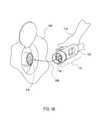
- FIGS. 1A and 1Billustrate a charging system according to some embodiments.
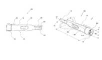
- FIG. 2is a side-view of a flexible electrical connector used in the charging system of FIG. 1A according to one embodiment.
- FIG. 3is a perspective view of the flexible electrical connector of FIG. 2 .
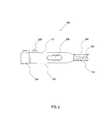
- FIG. 4is a perspective view of an electrical connector kit used in the charging system of FIG. 1A according to one embodiment.
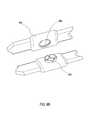
- FIG. 5is a perspective view of the electrical connector kit of FIG. 4 illustrating two detachable connector ends attached together.
- FIG. 6Ais a side view of an embodiment of the power cord of FIG. 1A with attachment mechanisms
- FIG. 6Bis a perspective view of one embodiment of an attachment mechanism of FIG. 6A .
- Electric motorscan also be powered by rechargeable batteries.
- Rechargeable batteriescan be used to power other devices besides vehicles. In both cases, current rechargeable battery technology typically requires hours for the batteries to recharge.
- the owner or operator of the vehicleis unlikely to remain with the vehicle for the entire recharging operation.
- the vehiclewill be located in a user's home or private parking garage or lot where it is protected from most malicious or accidental inference.
- some vehicle charging stationsare located in public places such as public parking lots, along public streets, or in public parking garages. Some of these public areas may have a lot of foot traffic near the vehicles. Since the re-charging operation may take place in a public area while the vehicle's owner or operator is not nearby, the connection between the vehicle and the power source may be subject to accidental or malicious contact or interference during the charging operation.
- a flexible electrical connectoris provided which can flex in at least one plane such that it can absorb some or all of the force of an impact rather than transferring the impact force to the electric vehicle or other power receiving device.
- FIGS. 1A and 1Billustrate a charging system 100 according to some embodiments.
- a power receiving device 102such as an at least partially electric vehicle containing a rechargeable battery pack 104 , is attached to a power supplying device 106 by means of a connection system 108 .
- the battery pack 104includes any device capable of storing electric energy such as batteries (e.g., lithium ion batteries, lead-acid batteries, nickel-metal hydride batteries, etc.), capacitors, reaction cells (e.g., Zn-air cell), etc.
- the battery pack 104comprises a plurality of individual batteries or battery cells/chemical modules.
- the connection system 108comprises a flexible electrical connector 200 (shown in FIG. 2 ) comprising a power cord 110 and a blade-shaped housing 112 on at least one end of the power cord 110 that is configured to detachably attach to the power receiving device 102 .
- a user 114attaches the blade-shaped housing 112 to the power receiving device 102 by inserting an end portion 116 of the blade-shaped housing 112 into a corresponding electrical interface 118 on the power receiving device 102 along insertion line 130 .
- the user 114inserts the end portion 116 of the blade-shaped housing 112 into the corresponding interface 118 by gripping a handle portion 120 of the blade-shaped housing 112 .
- this forceis 80N.
- the handle portion 120 of the blade-shaped housing 112remains rigid and does not flex in at least one plane (e.g., the vertical plane) to facilitate the user 114 gripping and inserting the blade-shaped housing 112 into the power receiving device 102 .
- the handle portion 120does not substantially compress along its length when the blade-shaped housing 112 is inserted into the power receiving device 102 .
- the other end of the power cord 110 remote from the blade-shaped housing 112is permanently attached to the power supplying device 106 .
- the power supplying device 106has a mechanism for retracting at least a portion of the power cord 110 , while in other embodiments the power supplying device 106 comprises a mechanism to retract substantially all of the power cord 110 into the housing of the power supplying device 106 when not in use.
- the power supplying device 106comprises a mechanism to restrain the power cord 110 near the housing of the power supplying device 106 when not in use.
- the power supplying device 106is a free standing charging post attached to the ground as shown in Design Application No. 29/312,808 herein incorporated by reference.
- the power supplying device 106is a wall mounted device. In some embodiments, the power supplying device 106 is ceiling mounted. In some embodiments, a plurality of power supplying devices 106 are interconnected to one another and are controlled by a remote computer.
- the connection system 108comprises a flexible connector kit 400 (shown in FIG. 4 ) comprising a power cord 110 , a blade-shaped housing 112 on one end of the power cord 110 and an additional housing 122 on the other end of the power cord 110 .
- the blade-shaped housing 112is configured to detachably connect to the power receiving device 102 .
- the additional housing 122is configured to detachably mate with the power supplying device 106 .
- the connector kit 400is carried by the user 114 and used to attach the power receiving device 102 to the power supplying device 106 when the power supplying device 106 is not equipped with a permanently attached flexible electrical connector 200 (described in relation to FIG. 2 .)
- the additional housing 122is similar to the blade-shaped housing 112 described in relation to FIGS. 2 and 3 , while in other embodiments, the additional housing 122 has additional features described in relation to FIGS. 4 and 5 .
- FIG. 2is a side-view of one embodiment of a flexible electrical connector 200 .
- the flexible electrical connector 200is configured to supply power to a power receiving device 102 .
- the power receiving device 102is an at least partially electric vehicle 103 containing one or more rechargeable battery packs 104 as shown in FIG. 1A .
- the flexible electrical connector 200comprises a blade-shaped housing 112 and a power cord 110 .
- the blade-shaped housing 112comprises an end portion 116 and an opposing handle portion 120 .
- the end portion 116contains an electrical interface 302 (shown in FIG. 3 ) that is configured to detachably mate with a corresponding electrical interface 118 of the power receiving device 102 (shown in FIG. 1B ).
- the cord 110extends from the handle portion 120 .
- the handle portion 120is configured to flex about the end portion 116 along an arc in a single plane (as shown in FIG. 3 .)
- the cord 110includes one or more power cables 202 and one or more data cables 204 .
- the power cables 202are capable of carrying high current and/or high voltage.
- the data 204 cablesare capable of carrying low current and/or low voltage.
- the end portion 116is made from a substantially rigid material.
- the substantially rigid materialis a hard plastic while in other embodiments, it is a metal.
- the end portion 116also comprises a lock 206 for fixing or locking the flexible electrical connector 200 to the power receiving device 102 .
- the lock 206is a biased lever as shown.
- the lockis a bolt or an electronically actuated lock.
- the user 114physically opens the lock 206 by depressing one end of the biased lever and keeping it depressed until the end portion 116 is properly inserted into the electrical interface 118 of the power receiving device 102 .
- the lock 206is unlocked by the user 114 physically unlocking and disengaging the flexible electrical connector 200 by depressing one end of the biased lever of the lock and keeping it depressed until the end portion 116 is completely removed from the electrical interface 118 of the power receiving device 102 .
- the lock 206 on the flexible electrical connector 200is also unlocked.
- a user 114may unlock an at least partially electric vehicle 103 using a key fob, and the act of unlocking the vehicle 103 also unlocks the flexible electrical connector 200 from the electrical interface 118 of the at least partially electric vehicle.
- the lock 206unlocks when the charging of the power receiving device 102 is cancelled by the user 114 , the power supplying device 116 , or by the electronic power grid.
- a combination of the abovemust be used to unlock the flexible electrical connector 200 from the power receiving device.
- the unlockingmay require that the user unlock the vehicle 103 and physically depress the biased lever lock 206 .
- the handle portion 120is made of a resilient material.
- the resilient materialis a cast urethane.
- the materialmay be rubber, a rubber based material, a polymer, plastic or any similar material having flexible and resilient properties.
- the handleis created using over-molding techniques.
- the handle portion 120is made of a mechanical jointed assembly allowing movement in a single plane.
- the handle portion 120is made of a mechanically jointed assembly of plastic and metal parts that allow movement substantially only in one plane (such as the X-Y plane of FIG. 3 .)
- the handle portion 112defines an opening or hole 208 there through to allow a user to better grip the handle portion 112 by sliding his fingers through the hole 208 .
- the hole 208is about an inch tall and four inches long. The hole 208 also decreases the total weight of the flexible electrical connector 200 . Furthermore, the hole 208 provides the handle portion 120 more flexibility than it would have without the hole.
- the blade-shaped housing 112has an emergency release option. For example, if the handle portion 120 bends beyond a predetermine flexibility or the cable is pulled beyond a predetermined tensile force, e.g., by the user accidentally driving away with the cable still plugged into the vehicle, the handle portion 120 breaks away from the end portion 116 . While in some embodiments, the release occurs at the interface between the handle portion 120 and the end portion 116 . In other embodiments, the breaking at any other suitable location along the connector and cable.
- FIG. 3is a perspective view of the flexible electrical connector 200 of FIG. 2 .
- the end portion 116contains an electrical interface 302 configured to mate with a corresponding electrical interface 118 of the power receiving device 102 (shown in FIG. 1B ).
- the electrical interface 302comprises a plurality of male electrical connector portions 304 configured to mate with corresponding female connector portions on the corresponding electrical interface 118 of the power receiving device 102 .
- one or more of the male electrical connector portions 304are configured for power transmission while one or more other male electrical connector portions are configured for data transmission.
- the electrical interface 302comprises a plurality of female connector portions while the male connector portions are on the corresponding electrical interface 118 of the power receiving device 102 .
- the cord 110is substantially flat.
- the flatness of the cordassists in retract-ability and fold-ability.
- the fold-ability aspectwill be discussed with relation to the flexible connector kit 400 the folding and storage of which is discussed in relation to FIG. 6 .
- the retract-ability aspectwas discussed in relation to the power supplying devices discussed with relation to FIGS. 1A and 1B .
- FIG. 3includes a coordinate system with the origin at a remote end of the end portion 116 .
- the blade shaped housing 112has a length L extending between a remote end of the end portion 116 and a remote end of the handle portion 120 along the X-axis. In some embodiments, the length L is seven inches.
- the blade shaped housing 112has a height H extending from a bottom edge to a top edge of the end portion 116 along positive and negative Z-axes. In some embodiments, the height H is two inches.
- the blade shaped portion 112has a width W extending from a first flat side of the blade-shaped housing 112 to a second flat side of the blade-shaped housing 112 along the positive and negative Y-axes.
- the width Wis 3 ⁇ 4 of an inch.
- the length Lis greater than the height H which is greater than the width W. In some embodiments, the length L is substantially larger than the height H which is substantially larger than the width W. In some embodiments the length L is at least twice as long as the height H which is at least twice as long as the width W. In some embodiments the length L is four times as long as the height H which is four times as long as the width W.
- the handle portion 120is made of a resilient material, while the end portion 116 is made of a substantially rigid material as discussed in relation to FIG. 2 .
- the blade-shaped housing 112has a length L greater than its height H which is greater than its width W.
- the combination of the shape of the blade-shaped housing 112 and the resilient material of the handle portion 120allows the handle portion 120 to flex about the substantially rigid end portion 116 .
- the movement or flexingoccurs along an arc in a single plane (the X-Y plane of FIG. 3 .)
- the power receiving device 102is an at least partially electric vehicle 103 containing a rechargeable battery pack 104 , and the single plane (the X-Y plane of FIG. 3 ) is parallel to a plane formed by a bottom surface of the at least partially electric vehicle 103 .
- Bending or flexing along an arc in a single planeis advantageous because the bending or flexing allows the blade-shaped housing 112 to absorb some or all of the force of an impact rather than transferring the impact force to the power receiving device 102 and/or its sensitive electrical components. For example, if the blade-shaped housing 112 is hit by a shopping cart in a parking lot it will not disengage from the power receiving device 102 , break, or damage the power receiving device's electrical interface 118 . Furthermore, allowing the flexing or bending in only a single plane, gives the blade-shaped housing sufficient rigidity in other dimensions to overcome the frictional resistance necessary to properly insert the end portion 116 of the blade-shaped housing 112 into the power receiving device's electrical interface 118 . As such the blade-shaped housing 112 allows only insubstantial bending and/or compression in other planes which provides the user 114 with a convenient handle for inserting into the power receiving device 102 for charging.
- the handle portion 120is configured to flex along a predetermined arc A° from a line extending from the handle portion 120 to the end portion 116 when the flexible electrical connector 200 is in a rest position.
- the handle portion 120 in this embodimentis configured to flex A° on either side of the X-axis.
- A°35°, i.e., the plus and minus 35° from a line extending from the handle portion 120 to the end portion 116 when the flexible electrical connector 200 is in a rest position.
- the handle portion 120 in this embodimentis configured to flex at least 35° on either side of the X-axis.
- the resilient material of the handle portion 120is resilient enough to allow the handle portion 120 to substantially bend back on itself.
- the handle portion 120cannot flex in other planes, other then the single plane (X-Y) described above.
- the handle portionremains substantially rigid in the X-Z plane because of the height H as compared to the width W of the blade-shaped housing 112 .
- the additional plane in which the handle portion 120 does not flexis perpendicular to the plane in which the handle portion 120 does flex.
- the handle portionflexes in the X-Y plane but remains substantially rigid in the X-Z plane because of the height H as compared to the width W of the blade-shaped housing 112 .
- the length L of the blade-shaped housing 112extends along a first plane (such as the X-Y plane of FIG. 3 ). In some embodiments, the height H extends parallel to a second plane (such as the X-Z plane of FIG. 3 ). In some embodiments, the width W extends parallel to a third plane orthogonal to said first and said second planes (such as the Y-Z plane of FIG. 3 ). In some embodiments, the handle portion 120 of the blade-shaped housing 112 is configured to flex about the end portion 116 of the blade-shaped housing 112 along an arc in the first plane (such as the X-Y plane of FIG. 3 ) which is orthogonal to the second and the third planes.
- the blade shaped housing 112attaches to the power receiving device 102 by inserting an end portion 116 of the blade-shaped housing 112 into a corresponding electrical interface 118 on the side of power receiving device 102 (such as the side of an at least partially electric vehicle 103 ). In other embodiments the end portion 116 of the blade-shaped housing 112 is inserted into a corresponding electrical interface 118 on the front or back of the power receiving device (such as the front or back of the at least partially electric vehicle.)
- the handle portion 120 of the blade-shaped housing 112is further configured to at least partially twist about a line extending from the end portion 116 to the handle portion 120 along its length.
- the handle portion 120is configured to twist along the X-axis.
- the twistingmay occur simultaneously with the flexing, in which case the line between the end portion 116 and the handle portion 120 about which the twisting occurs will not be straight or along the X-axis.
- the handle portion 120 of the blade-shaped housing 112is capable of bending in more than just a single plane. In some embodiments, the handle portion 120 of the blade-shaped housing 112 is also capable of twisting in these planes. In some embodiments, the handle portion 120 of the blade-shaped housing 112 can bend and twist in a variety of planes but is restrained from moving in at least one plane, such as being restrained from moving in a vertical direction (i.e., the Z-axis.) In other words, the handle portion 120 of the blade-shaped housing 112 does not flex in the X-Z plane of FIG. 3 . In other embodiments, the handle portion 120 of the blade-shaped housing 112 can at least partially flex in all directions although some planes of movement are easier than others.
- a flexible electrical connector 200for supplying power to a receiving device 102 wherein the flexible electrical connector 200 comprises a blade-shaped housing 112 having a handle portion 120 and an opposing end portion 116 , and a power cord 110 .
- the blade-shaped housinghas a length, a height, and a width, wherein the length extends between a remote end of the handle portion 120 to a remote end of the end portion 116 , and the length is larger than the height which is larger than the width.
- An electrical interface 302is located at the end portion 116 , wherein the electrical interface 302 is configured to detachably mate with a corresponding electrical interface 118 on an at least partially electric vehicle 103 .
- the power cord 110extends from the handle portion 120 of the blade-shaped housing 112 .
- the handle portion 120is configured to flex about the end portion 116 in a plurality of planes. In some embodiments, the handle portion 120 can flex in all directions. In some embodiments, the handle portion 120 can flex in some planes but is substantially restrained from flexing in at least one plane. In some embodiments, the plane in which the handle portion is substantially restrained from flexing is the X-Z plane shown in FIG. 3 .
- FIG. 4is a perspective view of an electrical connector kit 400 according to one embodiment.
- the flexible connector kit 400comprises a power cord 110 , a blade-shaped housing 112 on one end of the power cord 110 configured to detachably connect to the power receiving device 102 ( FIG. 1 ), and an additional housing 122 on the other end of the power cord 110 configured to detachably attach to the power supplying device 106 ( FIG. 1 ).
- the blade-shaped housing 112 of the connector kit 400comprises an end portion 116 and an opposing handle portion 120 .
- the end portion 116contains an electrical interface 302 (shown in FIG. 3 ) that is configured to detachably mate with a corresponding electrical interface 118 of the power receiving device 102 (shown in FIG. 1B ).
- the cord 110extends from the handle portion 120 , and the handle portion 120 is configured to flex about the end portion 116 along an arc in a single plane (as shown in FIG. 3 .)
- the additional housing 122 of the connector kit 400similarly comprises an end portion 416 and an opposing handle portion 420 .
- the end portion 416contains an electrical interface 402 that is configured to detachably mate with a corresponding electrical interface of the power supplying device 106 (shown in FIG. 1A ).
- the cord 110extends from the handle portion 420 to the handle portion 120 of the blade-shaped housing 112 .
- the electrical interface 402comprises a plurality of female electrical connector portions 404 configured to mate with corresponding male connector portions on the corresponding electrical interface of the power supplying device 106 ( FIG. 1 ). In some embodiments, one or more of the female electrical connector portions 404 are configured for power transmission while one or more other female electrical connector portions are configured for data transmission. In other embodiments the electrical interface 402 comprises a plurality of male connector portions while the female connector portions are on the corresponding electrical interface of the power supplying device 106 .
- the additional housing 122is substantially identical to the blade-shaped housing 112 .
- the handle portion 420 of the additional housing 122is also configured to flex about the end portion 416 along an arc in a single plane (similar to that shown in FIG. 3 .)
- the additional housing 122has a different shape than the blade-shaped housing 112 .
- FIG. 4illustrates an embodiment where the additional housing 122 has a triangular cross-sectional shape. Both the end portion 416 and the handle portion 420 have a triangular cross-section. In some embodiments, only the end portion 416 has a different shape, such as a triangular cross-section, as opposed to the circular cross-section of the end portion 116 of the blade-shaped housing 112 . In some embodiments, the end portion 116 of the blade-shaped housing 112 has a distinctly different shape than the end portion 416 of the additional housing 122 .
- the handle portion 420 of the additional housing 122has a circular cross-section which, if sufficiently small in diameter, allows it to flex about the end portion 416 in many planes.
- the additional housing 122further comprises a protruding element 408 .
- the protruding element 408is shaped to snuggly fit within hole 208 in the blade-shaped housing 112 , so that the kit can be folded and stored at described in relation to FIG. 5 .
- FIG. 5is a perspective view illustrating how the blade-shaped housing 112 and the additional housing 122 of the electrical connector kit 400 attach together according to some embodiments.
- the protruding element 408is shaped to fit in the hole 208 in the blade-shaped housing 112 (specifically the hole 208 in the handle portion 120 ) such that the protruding element 408 will remain at least partially frictionally restrained in the hole 208 after the protruding element 408 and the hole 208 have been pressed together.
- the handle portion 120 of the blade shaped housing 112 and the handle portion 120 of the additional housing 122 handle portion 420are both made of a substantially resilient material as discussed above with relation to FIG. 2 .
- the blade shaped housing 112 and the end portion 116 of the additional housing 122 end portion 416are both made of a substantially rigid material as discussed above with relation to FIG. 2 .
- the entire additional housing 122is made of a substantially rigid material.
- FIG. 6Ais a side view of an embodiment of the power cord 110 with attachment mechanisms 602 .
- the power cord 110has one or more attachment mechanisms 602 .
- FIG. 6Aillustrates the electrical connector kit 400 having two detachable connectors (the blade-shaped housing 112 and the additional housing 122 ).
- the attachment mechanisms 602are also useful in other embodiments such as the flexible electrical connector 200 of FIG. 2 .
- the connector mechanisms 602are useful in the connector kit 400 embodiment for aiding the user in folding up and neatly storing the connector kit 400 .
- the user 114can use the cable kit 400 to attach the power receiving device 102 to the power supplying device 106 for charging, and when the charging is complete the user 114 can fold up the cable kit elements, snap them together, and store them away until they are needed again.
- the cable kit 400can be stored in a bag, in the trunk, or a cable kit compartment in the door of an at least partially electric vehicle 103 .
- the power cord 110attaches to itself by the attachment mechanisms 602 , it is capable of being compactly stored and may be less likely to become tangled or damaged.
- the two detachable connectors (the blade-shaped housing 112 and the additional housing 122 ) of the electrical connector kit 400are additionally held together for neat storage by the mating of the protruding element 408 and hole 108 as discussed with relation to FIG. 5 .
- the power cord 110is substantially flat.
- the substantially flat cross section of the power cord 110allows it to more easily bend and fold into a compact space for storage and portability.
- the power cord 110houses both a power cable 202 and a data cable 204 .
- the one or more attachment mechanisms 602are on the flat portion of the power cord 110 .
- the attachment mechanisms 602are snaps such as metal snaps, hard plastic snaps, or flexible rubber snaps.
- the attachment mechanisms 602are magnets or electromagnets.
- the attachment mechanisms 602are clips.
- the attachment mechanisms 602are hook and loop elements such as VELCRO® patches, loops, and ribbons. In some embodiments, the attachment mechanisms are spaced equally along the length of the power cord 110 . In some embodiments, the power cord 110 may include crease lines to aid in bending the power cord 110 at particular predetermined points in order to align the attachment mechanisms 602 as well as the protruding element 408 and hole 208 ( FIG. 5 ).
- FIG. 6Bis a perspective view of one embodiment of an attachment mechanism 602 of FIG. 6A .
- the attachment element illustrated in FIG. 6Bis a snap having a male portion 604 and a female portion 606 .
- the male 604 and female 606 snapsare made of metal, plastic, or a resilient material similar to the material used for the handle portion 120 of the blade-shaped housing 112 described with relation to FIG. 2 .
Landscapes
- Engineering & Computer Science (AREA)
- Power Engineering (AREA)
- Transportation (AREA)
- Mechanical Engineering (AREA)
- Charge And Discharge Circuits For Batteries Or The Like (AREA)
- Connector Housings Or Holding Contact Members (AREA)
Abstract
Description
Claims (21)
Priority Applications (3)
| Application Number | Priority Date | Filing Date | Title |
|---|---|---|---|
| US12/559,462US7972167B2 (en) | 2009-09-14 | 2009-09-14 | Electrical connector with a flexible blade-shaped housing with a handle with an opening |
| PCT/US2010/048661WO2011032104A1 (en) | 2009-09-14 | 2010-09-13 | Flexible connector |
| US12/986,101US8246376B2 (en) | 2009-09-14 | 2011-01-06 | Electrical connector with flexible blade shaped handle |
Applications Claiming Priority (1)
| Application Number | Priority Date | Filing Date | Title |
|---|---|---|---|
| US12/559,462US7972167B2 (en) | 2009-09-14 | 2009-09-14 | Electrical connector with a flexible blade-shaped housing with a handle with an opening |
Related Child Applications (1)
| Application Number | Title | Priority Date | Filing Date |
|---|---|---|---|
| US12/986,101ContinuationUS8246376B2 (en) | 2009-09-14 | 2011-01-06 | Electrical connector with flexible blade shaped handle |
Publications (2)
| Publication Number | Publication Date |
|---|---|
| US20110065305A1 US20110065305A1 (en) | 2011-03-17 |
| US7972167B2true US7972167B2 (en) | 2011-07-05 |
Family
ID=43127792
Family Applications (2)
| Application Number | Title | Priority Date | Filing Date |
|---|---|---|---|
| US12/559,462Active - ReinstatedUS7972167B2 (en) | 2009-09-14 | 2009-09-14 | Electrical connector with a flexible blade-shaped housing with a handle with an opening |
| US12/986,101Active2030-01-10US8246376B2 (en) | 2009-09-14 | 2011-01-06 | Electrical connector with flexible blade shaped handle |
Family Applications After (1)
| Application Number | Title | Priority Date | Filing Date |
|---|---|---|---|
| US12/986,101Active2030-01-10US8246376B2 (en) | 2009-09-14 | 2011-01-06 | Electrical connector with flexible blade shaped handle |
Country Status (2)
| Country | Link |
|---|---|
| US (2) | US7972167B2 (en) |
| WO (1) | WO2011032104A1 (en) |
Cited By (12)
| Publication number | Priority date | Publication date | Assignee | Title |
|---|---|---|---|---|
| US20110200193A1 (en)* | 2010-02-12 | 2011-08-18 | Daniel Ray Blitz | Method and apparatus for controlling the recharging of electric vehicles and detecting stolen vehicles and vehicular components |
| US20110300736A1 (en)* | 2010-06-08 | 2011-12-08 | Kabushiki Kaisha Tokai Rika Denki Seisakusho | Locking device for power feeding plug |
| US20120193929A1 (en)* | 2010-07-23 | 2012-08-02 | Electric Transportation Engineering Corp., dba ECOtality North America | Device to facilitate moving an electrical cable of an electric vehicle charging station and method of providing the same |
| US8414339B1 (en) | 2011-10-31 | 2013-04-09 | Lear Corporation | Electrical terminal and receptacle assembly |
| US8678867B2 (en) | 2011-10-31 | 2014-03-25 | Lear Corporation | Electrical terminal and receptacle assembly |
| US8890475B1 (en)* | 2010-09-28 | 2014-11-18 | Gilbert Scott Becker | Automobile charging and communications station |
| US20150183331A1 (en)* | 2012-09-19 | 2015-07-02 | Nissan Motor Co., Ltd. | External charging structure for an electric vehicle |
| US9236682B2 (en) | 2013-02-15 | 2016-01-12 | Lear Corporation | Cylindrical electric connector with biased contact |
| US20180028736A1 (en)* | 2016-07-27 | 2018-02-01 | Tc1 Llc | Fluid resistant locking electrical connector for ventricular assist devices |
| USD813873S1 (en) | 2017-02-21 | 2018-03-27 | Verily Life Sciences Llc | Electronic connector for charging or data transfer |
| US9935408B1 (en) | 2017-06-16 | 2018-04-03 | Verily Life Sciences Llc | Electronic connector for charging or data transfer |
| US20190077271A1 (en)* | 2017-09-08 | 2019-03-14 | SparkCharge, Inc. | Electric charging system for electric cars |
Families Citing this family (40)
| Publication number | Priority date | Publication date | Assignee | Title |
|---|---|---|---|---|
| US7751907B2 (en) | 2007-05-24 | 2010-07-06 | Smiths Medical Asd, Inc. | Expert system for insulin pump therapy |
| WO2012148596A1 (en) | 2011-04-29 | 2012-11-01 | Electric Transportation Engineering Corporation, D/B/A Ecotality North America | System for measuring electricity and method of providing and using the same |
| US8834202B2 (en) | 2011-06-13 | 2014-09-16 | Lear Corporation | Connector assembly for vehicle charging |
| USD666152S1 (en) | 2012-02-28 | 2012-08-28 | Lear Corporation | Connector assembly |
| US9327606B2 (en)* | 2011-07-01 | 2016-05-03 | Toyota Jidosha Kabushiki Kaisha | Charging apparatus |
| US9793642B2 (en) | 2011-08-22 | 2017-10-17 | Lear Corporation | Connector assembly |
| JP5099281B1 (en)* | 2012-03-15 | 2012-12-19 | トヨタ自動車株式会社 | Extraction device |
| GB2500669B (en)* | 2012-03-29 | 2016-03-30 | Icon Polymer Group | Hose for conveying fluid |
| US9381297B2 (en)* | 2012-06-07 | 2016-07-05 | Tandem Diabetes Care, Inc. | Sealed infusion device with electrical connector port |
| CN102801071A (en)* | 2012-08-24 | 2012-11-28 | 东莞市钜大电子有限公司 | Cables for easy storage |
| US9455542B2 (en)* | 2012-11-23 | 2016-09-27 | Wayne Gaither | Power cord apparatus and method of using same |
| FR3004587B1 (en)* | 2013-04-11 | 2015-04-17 | Peugeot Citroen Automobiles Sa | MODULAR POWER SUPPLY FOR A MOTOR VEHICLE |
| CN203423568U (en)* | 2013-08-21 | 2014-02-05 | 中山大洋电机股份有限公司 | Motor lead sheath structure and motor applying same |
| DE112015003660A5 (en) | 2014-08-07 | 2017-07-13 | Bayerische Motoren Werke Aktiengesellschaft | Vehicle with a rechargeable by means of a charging cable and an external power storage device |
| DE102014215665A1 (en)* | 2014-08-07 | 2016-02-11 | Bayerische Motoren Werke Aktiengesellschaft | Vehicle and charging cable for use with a vehicle |
| DE102014215668A1 (en)* | 2014-08-07 | 2016-02-11 | Bayerische Motoren Werke Aktiengesellschaft | Vehicle and cable cradle |
| US10027148B2 (en) | 2016-03-04 | 2018-07-17 | Ford Global Technologies, Llc | Portable electric vehicle supply equipment (EVSE) system |
| US9873408B2 (en)* | 2016-05-11 | 2018-01-23 | Peter D. Capizzo | Device for refueling, exchanging, and charging power sources on remote controlled vehicles, UAVs, drones, or any type of robotic vehicle or machine with mobility |
| US9876889B1 (en)* | 2016-07-13 | 2018-01-23 | Play Impossible Corporation | Smart playable device and charging systems and methods |
| USD861617S1 (en)* | 2016-08-02 | 2019-10-01 | Eucrea Hexagon Holding Gmbh | Electrical connector |
| USD960839S1 (en)* | 2017-10-31 | 2022-08-16 | Dietmar Niederl | Electrical connector |
| JP1610737S (en)* | 2017-12-26 | 2018-08-06 | ||
| EP3525215A1 (en)* | 2018-02-08 | 2019-08-14 | Nexans | Tangle free cable sytem |
| DE102018211507A1 (en)* | 2018-07-11 | 2020-01-16 | Bayerische Motoren Werke Aktiengesellschaft | Charging device for charging a battery of an electrically operated motor vehicle |
| NL2023045B1 (en)* | 2019-05-01 | 2020-12-02 | Prysmian Spa | Cable assembly |
| EP3771045A1 (en)* | 2019-07-25 | 2021-01-27 | ABB Schweiz AG | Charging arrangement for charging of electric vehicles |
| CN110758156B (en)* | 2019-11-19 | 2020-08-11 | 冯孝金 | Electric pile is filled in sharing of outdoor use |
| US11704749B2 (en)* | 2019-11-25 | 2023-07-18 | Itron Global Sarl | Networked utility services and vehicle charging stations |
| USD944205S1 (en)* | 2020-01-03 | 2022-02-22 | The Noco Company | Electrical connector |
| USD967027S1 (en) | 2020-01-03 | 2022-10-18 | The Noco Company | USB-C port with circuit board |
| CN111668658A (en)* | 2020-08-10 | 2020-09-15 | 大连理工江苏研究院有限公司 | Flexible charging terminal of electric automobile charging pile |
| EP4180265A1 (en)* | 2021-11-15 | 2023-05-17 | Lapp Engineering AG | Charging cable for vehicles with an electric drive |
| USD1046783S1 (en) | 2021-12-29 | 2024-10-15 | GoPlug Inc. | Electrical vehicle charging connector |
| USD979512S1 (en) | 2022-04-04 | 2023-02-28 | GoPlug Inc. | Electrical connector |
| FR3134354B1 (en)* | 2022-04-11 | 2024-09-13 | Renault Sas | Electrical charging cord holder of a motor vehicle. |
| DE202022102059U1 (en) | 2022-04-17 | 2023-07-19 | SMA Solar Technology AG | Charging station for charging an electrical energy store in a motor vehicle with a cable holder |
| US12341330B2 (en) | 2022-08-19 | 2025-06-24 | Dana Automotive Systems Group, Llc | High voltage cable stay grommet |
| GB2625569B (en)* | 2022-12-20 | 2024-12-18 | Harrison Robert | Mobile vehicle charging |
| FR3152441A1 (en)* | 2023-09-05 | 2025-03-07 | Renault S.A.S. | Electrical charging cord holder of a motor vehicle. |
| USD1067188S1 (en)* | 2024-09-20 | 2025-03-18 | Zhiyi Wang | Charging adapter |
Citations (11)
| Publication number | Priority date | Publication date | Assignee | Title |
|---|---|---|---|---|
| US3197830A (en)* | 1964-05-01 | 1965-08-03 | Hoadley Robert Bruce | Keeper for electrical cords |
| US4846697A (en) | 1987-11-02 | 1989-07-11 | Rodgers E Walter | Cable for interconnecting lighting systems of towing vehicle and trailer |
| EP0644625A2 (en) | 1993-04-22 | 1995-03-22 | Sumitomo Wiring Systems, Ltd. | Electric vehicle charging connector assembly |
| EP0692849A1 (en) | 1994-07-12 | 1996-01-17 | Société d'Exploitation des Procédés Maréchal (SEPM), société anonyme | Movable element for electrical connection and electrical connecting cable with gripping device |
| US5535274A (en)* | 1991-10-19 | 1996-07-09 | Cellport Labs, Inc. | Universal connection for cellular telephone interface |
| US5614808A (en)* | 1993-05-10 | 1997-03-25 | Sumitomo Wiring Systems, Ltd. | Electric vehicle charging connector, connector assembly and electric vehicle charging system |
| US5758414A (en) | 1994-04-28 | 1998-06-02 | Hubbell Incorporated | Method of making universal electrical connector |
| US5906500A (en) | 1996-10-04 | 1999-05-25 | Yazaki Corporation | Charging connector for electric vehicle |
| US6123569A (en)* | 1995-12-06 | 2000-09-26 | Yazaki Corporation | Charging connector for electric vehicle |
| US6204505B1 (en)* | 1998-10-06 | 2001-03-20 | Neoprobe Corporation | Surgical probe apparatus and system |
| US20070241721A1 (en)* | 2005-03-21 | 2007-10-18 | Eveready Battery Company, Inc. | Direct current power supply |
Family Cites Families (164)
| Publication number | Priority date | Publication date | Assignee | Title |
|---|---|---|---|---|
| US3690397A (en) | 1970-12-16 | 1972-09-12 | Louis W Parker | Electric automobile |
| US3799063A (en) | 1972-08-16 | 1974-03-26 | D Reed | Vehicle battery changing device |
| DE2241548B1 (en) | 1972-08-24 | 1973-10-31 | Messerschmitt-Boelkow-Blohm Gmbh, 8000 Muenchen | Installation arrangement for replaceable batteries in an electric vehicle |
| US4052655A (en) | 1975-09-10 | 1977-10-04 | Joseph Vizza | Battery recharging meter |
| CH602374A5 (en) | 1975-12-24 | 1978-07-31 | Voith Gmbh J M | |
| US4338587A (en) | 1979-02-23 | 1982-07-06 | Chiappetti Arthur B | Toll collection system |
| US4532511A (en) | 1979-10-12 | 1985-07-30 | Lemelson Jerome H | Automatic vehicle identification system and method |
| USD270831S (en) | 1980-02-15 | 1983-10-04 | Common Sense Products Pty. Ltd. | Multiple service unit |
| US4352992A (en) | 1980-02-27 | 1982-10-05 | Regency Electronics, Inc. | Apparatus for addressably controlling remote units |
| US4309644A (en) | 1980-05-05 | 1982-01-05 | Eberhart Reimers | Electric vehicle controller adapted for charge station connection |
| US4383210A (en) | 1980-06-18 | 1983-05-10 | Wilkinson Rudolph P | Apparatus and method for recharging an energy storage device |
| GB2083301B (en) | 1980-09-01 | 1984-09-26 | South Eastern Elec Board | Method of and apparatus for controlling loads on an electrical power supply |
| US4347472A (en) | 1980-10-20 | 1982-08-31 | Lemelson Jerome H | Apparatus and method for charging a battery in a vehicle |
| US4365681A (en) | 1980-12-22 | 1982-12-28 | General Motors Corporation | Battery support structure |
| US4404641A (en) | 1981-02-17 | 1983-09-13 | Dierckx Equipment Corporation | Maintenance monitor |
| US4709202A (en) | 1982-06-07 | 1987-11-24 | Norand Corporation | Battery powered system |
| US4532418A (en) | 1982-08-30 | 1985-07-30 | The Detroit Edison Company | Microprocessor electric vehicle charging and parking meter system structure and method |
| USD274126S (en) | 1982-09-17 | 1984-06-05 | Datakey, Inc. | Electronic information key |
| USD286040S (en) | 1983-12-27 | 1986-10-07 | Lavalle James G | Electrical fixture for marinas |
| USD286854S (en) | 1984-05-14 | 1986-11-25 | Fane William J | Key for door locks |
| DE3439038A1 (en) | 1984-10-25 | 1986-04-30 | Wolfgang 4925 Kalletal Benstein | Covering for assembly pits |
| FR2583186B1 (en) | 1985-06-07 | 1987-10-02 | Flonic Sa | PAID PARKING MANAGEMENT SYSTEM |
| USD299821S (en) | 1985-11-12 | 1989-02-14 | Sea Technology, Ltd. | Lower and utility distribution pedestal for boats and recreational vehicles |
| DE3605627A1 (en) | 1986-02-21 | 1987-08-27 | Elektron Bremen | METHOD AND DEVICE FOR TRANSMITTING THE DATA FROM A VOLTAGE SOURCE (BATTERY) TO A DATA PROCESSING SYSTEM |
| US4791871A (en) | 1986-06-20 | 1988-12-20 | Mowll Jack U | Dual-mode transportation system |
| US4800328A (en) | 1986-07-18 | 1989-01-24 | Inductran Inc. | Inductive power coupling with constant voltage output |
| US4967895A (en) | 1987-04-16 | 1990-11-06 | Pom, Incorporated | Parameter control system for electronic parking meter |
| US4880097A (en) | 1987-04-16 | 1989-11-14 | Pom Incorporated | Park card system for electronic parking meter |
| USD308267S (en) | 1987-04-20 | 1990-05-29 | The Hoover Company | Storage rack for a vacuum cleaner and tools |
| EP0290396A1 (en) | 1987-05-06 | 1988-11-09 | Hans-Reinhard Knepper | Power supply arrangement |
| FR2615304B1 (en) | 1987-05-14 | 1992-11-27 | Innovation Sa Ste Internale | TIME ACCOUNTING SYSTEM, IN PARTICULAR FOR THE ACCOUNTING OF PAID PARKING TIMES |
| US4789047A (en) | 1987-07-22 | 1988-12-06 | Knobloch Peter C | Motor vehicle servicing system |
| CA1292319C (en) | 1987-08-10 | 1991-11-19 | Mike T. Chan | Parking meters capable of being operated without monetary coins |
| DE3736481C2 (en) | 1987-10-28 | 1996-10-02 | Graesslin Kg | Method and device for determining the energy content of electrochemical energy stores |
| USD307580S (en) | 1988-02-02 | 1990-05-01 | Central Systems & Controls Corporation | Pedestal mounted marine power source |
| DE3815001A1 (en) | 1988-05-03 | 1989-11-16 | Ullmann Ulo Werk | DEVICE FOR CHARGING ACCUMULATORS |
| US5159272A (en) | 1988-07-27 | 1992-10-27 | Gnb Incorporated | Monitoring device for electric storage battery and configuration therefor |
| JPH0776733B2 (en) | 1988-09-07 | 1995-08-16 | 富士重工業株式会社 | Vehicle diagnostic system |
| USD314182S (en) | 1988-10-20 | 1991-01-29 | Moerman Paul G | Temporary utility pedestal |
| US4876513A (en) | 1988-12-05 | 1989-10-24 | Globe-Union Inc. | Dynamic state-of-charge indicator for a battery and method thereof |
| US5058044A (en) | 1989-03-30 | 1991-10-15 | Auto I.D. Inc. | Automated maintenance checking system |
| DE69006885T3 (en) | 1989-04-14 | 1999-05-20 | Hitachi, Ltd., Tokio/Tokyo | Control device for cars. |
| US4960150A (en) | 1989-06-30 | 1990-10-02 | Alex Ryan | Movable safety cover for vehicle service pit |
| US5049802A (en) | 1990-03-01 | 1991-09-17 | Caterpillar Industrial Inc. | Charging system for a vehicle |
| US5590749A (en) | 1990-03-14 | 1997-01-07 | Magic Electrical Products L.L.C. | Electrical cord retraction device |
| US5072380A (en) | 1990-06-12 | 1991-12-10 | Exxon Research And Engineering Company | Automatic vehicle recognition and customer billing system |
| EP0476405A1 (en) | 1990-09-20 | 1992-03-25 | Maschinenfabrik Rieter Ag | Automatic storage monitoring and battery exchange system for electrically driven transport vehicles |
| US5189836A (en) | 1990-11-07 | 1993-03-02 | Alder Matt L | Automated inspection pit cover system |
| GB2253379B (en) | 1991-02-13 | 1995-04-26 | Nelson James Kruschandl | Comprehensive electric motor road vehicle system |
| US5184058A (en) | 1991-05-20 | 1993-02-02 | The Fleming Group | Method and system for electricity storage and discharge |
| AU669853B2 (en) | 1991-08-01 | 1996-06-27 | Ea Technology Limited | Battery powered electric vehicle and electrical supply system |
| US5230637A (en)* | 1991-09-09 | 1993-07-27 | Weber William P | Battery jumper cable |
| US5341083A (en) | 1991-09-27 | 1994-08-23 | Electric Power Research Institute, Inc. | Contactless battery charging system |
| US5157319A (en) | 1991-09-27 | 1992-10-20 | Electric Power Research Institute | Contactless battery charging system |
| US5202617A (en) | 1991-10-15 | 1993-04-13 | Norvik Technologies Inc. | Charging station for electric vehicles |
| US5206578A (en) | 1991-10-15 | 1993-04-27 | Norvik Technologies Inc. | Monitoring system for batteries during charge and discharge |
| FR2685547A1 (en) | 1991-12-20 | 1993-06-25 | Zibell Laurent | Energy supply device for an electric vehicle |
| IT1250897B (en) | 1991-12-24 | 1995-04-21 | Fiat Auto Spa | AUTONOMY INDICATOR DEVICE FOR A ACCUMULATOR VEHICLE. |
| JP2776105B2 (en) | 1992-01-07 | 1998-07-16 | 三菱電機株式会社 | Electronic device and method for supplying power to electronic device |
| EP0552737A1 (en) | 1992-01-22 | 1993-07-28 | Hughes Aircraft Company | Weatherized curb-side charger |
| US5297664A (en) | 1992-06-26 | 1994-03-29 | Tseng Ling Yuan | Electric charging/parking meter |
| US5563491A (en) | 1992-03-30 | 1996-10-08 | Tseng; Ling-Yuan | Combined parking meter and electric-vehicle battery charger with remote status receiver |
| FR2696139A1 (en) | 1992-09-28 | 1994-04-01 | Garrigou Joel | Traction battery exchange station for electrically driven automobiles - has chain conveyor delivery system from vertically stacked battery store to battery-changing pit under vehicle platform. |
| US5349535A (en) | 1992-10-20 | 1994-09-20 | Digicomp Research Corporation | Battery condition monitoring and recording system for electric vehicles |
| GR920100495A (en) | 1992-11-11 | 1994-07-29 | Panagiotis Anagnostopoulos | Complete and unified guided method offering control, information, protection, communication and performance of procedures, suitable mainly for individuals, vehicles, buildings of city centres and other extensive areas. |
| US5263565A (en) | 1992-11-23 | 1993-11-23 | Wilkinson Rudolph P | Combination parking meter and electric energy dispensing apparatus and method |
| JP2978348B2 (en)* | 1992-12-18 | 1999-11-15 | 矢崎総業株式会社 | Power supply connector |
| US5306999A (en) | 1993-01-15 | 1994-04-26 | Hubbell Incorporated | Electric vehicle charging station |
| US5413493A (en) | 1993-01-15 | 1995-05-09 | Hubbell Incorporated | Electrical connector assembly, especially for electric vehicle |
| US5315227A (en) | 1993-01-29 | 1994-05-24 | Pierson Mark V | Solar recharge station for electric vehicles |
| USD349099S (en) | 1993-03-18 | 1994-07-26 | Motorola, Inc. | Remote electrical connector |
| US5373910A (en) | 1993-04-08 | 1994-12-20 | Nixon; Dale B. | Method of operation for an electric vehicle having multiple replacement batteries |
| US5462439A (en) | 1993-04-19 | 1995-10-31 | Keith; Arlie L. | Charging batteries of electric vehicles |
| US5369352A (en) | 1993-04-26 | 1994-11-29 | Ford Motor Company | Universal electric vehicle charging adapter |
| US5346406A (en) | 1993-04-30 | 1994-09-13 | Hubbell Incorporated | Electrical cable and connector assembly with safety pilot line disconnect, especially for electric vehicle |
| US5327066A (en) | 1993-05-25 | 1994-07-05 | Intellectual Property Development Associates Of Connecticut, Inc. | Methods and apparatus for dispensing a consumable energy source to a vehicle |
| US5422624A (en) | 1993-05-25 | 1995-06-06 | Intellectual Property Development Associates Of Connecticut, Inc. | Methods and apparatus for inputting messages, including advertisements, to a vehicle |
| US6727809B1 (en) | 1993-05-25 | 2004-04-27 | Intellectual Property Development Associates Of Connecticut, Inc. | Methods for providing information, messages and advertisements to a user of a fuel pump that is coupled to remote computers through a data communications network |
| JPH0717265A (en) | 1993-07-06 | 1995-01-20 | Nippon Home Keizai Kenkyusho:Kk | Vehicle mounting device for secondary battery for electric vehicle power |
| JP3385657B2 (en) | 1993-08-10 | 2003-03-10 | トヨタ自動車株式会社 | Car navigation system |
| JP3177806B2 (en) | 1993-09-17 | 2001-06-18 | 本田技研工業株式会社 | Display device for electric vehicle |
| GB9322137D0 (en) | 1993-10-27 | 1993-12-15 | Logical Water Limited | A system and method for defining a process structure for performing a task |
| FR2713019B1 (en) | 1993-11-23 | 1995-12-22 | Thomson Csf | Method and device for monitoring and dynamic balancing of a pack of accumulator batteries. |
| DE4344369C2 (en) | 1993-12-24 | 1997-12-11 | Daimler Benz Ag | Consumption-oriented mileage limitation of a vehicle drive |
| JP3112226B2 (en) | 1993-12-27 | 2000-11-27 | 矢崎総業株式会社 | Charging connector for electric vehicles |
| US5711648A (en) | 1994-01-06 | 1998-01-27 | Unlimited Range Electric Car Systems Company | Battery charging and transfer system |
| US5927938A (en) | 1994-01-06 | 1999-07-27 | Unlimited Range Electric Car Systems Company | Battery charging and transfer system for electrically powered vehicles |
| US5573090A (en) | 1994-05-05 | 1996-11-12 | H. R. Ross Industries, Inc. | Raodway-powered electric vehicle system having onboard power metering and communication channel features |
| US5631536A (en) | 1994-05-16 | 1997-05-20 | Tseng; Ling-Yuan | Rechargeable battery vending apparatus |
| FR2721559B1 (en) | 1994-06-23 | 1996-08-30 | Belaud Maurice Joseph | Process for optimizing the performance and the autonomy of electrically propelled vehicles with the assistance and logistics infrastructures specially designed for the implementation of this process. |
| SE503254C2 (en) | 1994-07-04 | 1996-04-29 | Vattenfall Ab | Electricity distribution network, method and apparatus for regulating electrical current from the grid |
| US5453585A (en) | 1994-07-20 | 1995-09-26 | Golden West Communications, Inc. | Cable retraction system |
| JP3450906B2 (en) | 1994-08-25 | 2003-09-29 | 本田技研工業株式会社 | Charge control device for electric vehicles |
| US5612606A (en) | 1994-09-15 | 1997-03-18 | David C. Guimarin | Battery exchange system for electric vehicles |
| USD373192S (en) | 1994-11-09 | 1996-08-27 | The Kendall Company | Connector for a device for applying compressive pressure to the leg |
| US5701706A (en) | 1995-02-23 | 1997-12-30 | Kreysler; William | Underground service bay for vehicles and process for constructing same |
| JP3264123B2 (en) | 1995-03-06 | 2002-03-11 | 三菱自動車工業株式会社 | Navigation system for hybrid electric vehicles |
| US5703461A (en) | 1995-06-28 | 1997-12-30 | Kabushiki Kaisha Toyoda Jidoshokki Seisakusho | Inductive coupler for electric vehicle charger |
| FR2737694B1 (en) | 1995-08-09 | 1997-09-26 | Belaud Maurice Joseph | METHOD FOR ADAPTING ON-BOARD ENERGY TO THE NEEDS OF ELECTRIC VEHICLES OF DIFFERENT TYPES AND GAMES WITH DEVICES SPECIALLY DESIGNED FOR IMPLEMENTATION |
| EP0788212B1 (en) | 1996-01-30 | 2002-04-17 | Sumitomo Wiring Systems, Ltd. | Connection system and connection method for an electric automotive vehicle |
| DE19621668A1 (en) | 1996-05-30 | 1997-12-04 | Uwe Kochanneck | Multi=block robot system e.g. for logistics and power supply to electric vehicles |
| US6331762B1 (en) | 1997-11-03 | 2001-12-18 | Midtronics, Inc. | Energy management system for automotive vehicle |
| US5979605A (en) | 1996-10-23 | 1999-11-09 | Popp; Thomas J. | Adjustable vehicle service area and service walkway |
| WO1998021132A1 (en) | 1996-11-12 | 1998-05-22 | Unlimited Range Electric Car Systems Company | Battery charging and exchange system for electrically powered vehicles |
| US5806500A (en)* | 1997-02-03 | 1998-09-15 | Ford Motor Company | Fuel vapor recovery system |
| US7216043B2 (en) | 1997-02-12 | 2007-05-08 | Power Measurement Ltd. | Push communications architecture for intelligent electronic devices |
| US6177879B1 (en) | 1997-05-09 | 2001-01-23 | Honda Giken Kogyo Kabushiki Kaisha | Battery rental system and apparatus |
| US6240684B1 (en) | 1997-07-02 | 2001-06-05 | William H. Bigelow | Portable automotive service building |
| US5913917A (en) | 1997-08-04 | 1999-06-22 | Trimble Navigation Limited | Fuel consumption estimation |
| US6088963A (en) | 1997-08-26 | 2000-07-18 | Cawthon; Mark C. | Automotive bay pit cover with panels having tapered ends for vertical stacking |
| US6871151B2 (en) | 1997-11-03 | 2005-03-22 | Midtronics, Inc. | Electronic battery tester with network communication |
| US7774151B2 (en) | 1997-11-03 | 2010-08-10 | Midtronics, Inc. | Wireless battery monitor |
| US6157292A (en) | 1997-12-04 | 2000-12-05 | Digital Security Controls Ltd. | Power distribution grid communication system |
| USD415111S (en) | 1998-01-02 | 1999-10-12 | Monster Cable Products, Inc. | Connector hood for electrical cable |
| USD429622S (en) | 1998-02-02 | 2000-08-22 | Tuthill Corporation | Security key for fuel dispenser |
| US6114632A (en) | 1998-03-05 | 2000-09-05 | Planas, Sr.; Alberto E. | Integrated power and data communication hybrid cable assembly for local area computer network |
| US6371768B1 (en)* | 1998-03-31 | 2002-04-16 | Daimlerchrysler Corporation | Universal charge port connector for electric vehicles |
| US5998963A (en) | 1998-06-11 | 1999-12-07 | Aarseth; Einar | Electric vehicle service center and method for exchanging and charging vehicle batteries |
| USD420644S (en) | 1998-12-22 | 2000-02-15 | Nemal Electronics International, Inc. | Twelve channel audio cable connector |
| US20030209375A1 (en) | 1999-01-25 | 2003-11-13 | Zip Charge Corporation | Electrical vehicle energy supply system, electrical vehicle battery, electrical vehicle battery charging apparatus, battery supply apparatus, and electrical vehicle battery management system |
| TW412097U (en) | 1999-01-28 | 2000-11-11 | Ind Tech Res Inst | Select-type battery-charging station for managing and switching the batteries of electric vehicles |
| USD434001S (en) | 1999-08-09 | 2000-11-21 | Sayger Jack M | Utility box |
| JP2001167954A (en) | 1999-12-06 | 2001-06-22 | Toyota Autom Loom Works Ltd | Power receiving side coupler for charging and electromagnetic induction type power receiving side charging device |
| US20020026252A1 (en) | 2000-05-15 | 2002-02-28 | Wruck William J. | Computer system for vehicle battery selection based on vehicle operating conditions |
| US7256516B2 (en) | 2000-06-14 | 2007-08-14 | Aerovironment Inc. | Battery charging system and method |
| JP3735011B2 (en) | 2000-07-03 | 2006-01-11 | 矢崎総業株式会社 | Assembly method of hybrid connector |
| US6631775B1 (en) | 2000-07-06 | 2003-10-14 | George T. Chaney | Electric vehicle chassis with removable battery module and a method for battery module replacement |
| WO2002080332A1 (en) | 2001-03-30 | 2002-10-10 | Designline Limited | Battery management unit, system and method |
| US6487477B1 (en) | 2001-05-09 | 2002-11-26 | Ford Global Technologies, Inc. | Strategy to use an on-board navigation system for electric and hybrid electric vehicle energy management |
| JP3758140B2 (en) | 2001-07-09 | 2006-03-22 | 日産自動車株式会社 | Information presentation device |
| US6539678B1 (en) | 2001-07-16 | 2003-04-01 | Robert E. Campbell | Vehicle service bay |
| US7158008B2 (en) | 2002-03-29 | 2007-01-02 | Datakey Electronincs, Inc. | Electronic key system and method |
| US20040044452A1 (en) | 2002-08-29 | 2004-03-04 | Lester Electrical Of Nebraska, Inc. | Vehicle monitoring system |
| JP3956814B2 (en) | 2002-09-18 | 2007-08-08 | トヨタ自動車株式会社 | High voltage equipment storage box |
| CN1751320A (en) | 2003-02-19 | 2006-03-22 | 松下电器产业株式会社 | information providing device |
| US7411371B2 (en) | 2003-02-28 | 2008-08-12 | Arizona Public Service Company | Battery charger and method of charging a battery |
| US7339347B2 (en) | 2003-08-11 | 2008-03-04 | Reserve Power Cell, Llc | Apparatus and method for reliably supplying electrical energy to an electrical system |
| DE10338279B4 (en) | 2003-08-20 | 2007-07-26 | Siemens Ag | connector device |
| USD515033S1 (en) | 2003-10-09 | 2006-02-14 | Bretford Manufacturing, Inc. | Modular system support |
| US7575828B2 (en) | 2004-07-23 | 2009-08-18 | Kim Manufacturing Co. | Modular rack assemblies for sealed lead acid batteries |
| USD517591S1 (en) | 2004-07-28 | 2006-03-21 | Casio Keisanki Kabushiki Kaisha | White key of an electronic keyboard musical instrument |
| US7444192B2 (en) | 2004-10-26 | 2008-10-28 | Aerovironment, Inc. | Reactive replenishable device management |
| CN1261319C (en) | 2004-11-11 | 2006-06-28 | 北京电巴科技有限公司 | An electric bus system |
| JP2006147305A (en) | 2004-11-18 | 2006-06-08 | Mitsumi Electric Co Ltd | Floating connector |
| JP4373941B2 (en) | 2005-02-23 | 2009-11-25 | 本田技研工業株式会社 | Fuel supply station information distribution system, fuel supply station information distribution server, and fuel supply station information display device |
| US7489105B2 (en)* | 2005-03-21 | 2009-02-10 | Eveready Battery Company, Inc. | Portable power supply |
| US7349800B2 (en) | 2005-04-12 | 2008-03-25 | International Business Machines Corporation | Adaptable navigation system |
| USD522963S1 (en) | 2005-04-14 | 2006-06-13 | Microsoft Corporation | Housing for a battery charger |
| US7520111B2 (en) | 2005-06-10 | 2009-04-21 | Cnh America Llc | Stone detection method and apparatus for a harvester |
| US7602143B2 (en) | 2005-11-04 | 2009-10-13 | Peter David Capizzo | System for replenishing energy sources onboard different types of automotive vehicles |
| USD559785S1 (en) | 2006-02-09 | 2008-01-15 | Bien-Air Holding Sa | Connector |
| JP5162998B2 (en) | 2006-10-12 | 2013-03-13 | 日産自動車株式会社 | Hybrid vehicle mode switching control device |
| KR20090119832A (en) | 2006-12-11 | 2009-11-20 | 브이2그린, 인코포레이티드 | Scheduling and control in a power aggregation system for distributed electric resources |
| DE102007032210B4 (en) | 2007-04-19 | 2010-04-08 | Höltzel, Thomas | Method and device for replacing accumulators for electric vehicles |
| US7740501B2 (en) | 2007-06-06 | 2010-06-22 | Claudio R. Ballard | Hybrid cable for conveying data and power |
| EP2235692B1 (en) | 2007-12-21 | 2012-12-19 | Renault Trucks | Process for updating the scheduling of a service stop for a machine |
| USD607831S1 (en) | 2008-01-04 | 2010-01-12 | Apple Inc. | Connector |
| JP5560557B2 (en) | 2008-02-27 | 2014-07-30 | 日産自動車株式会社 | Battery control device |
| US8414450B2 (en) | 2008-03-03 | 2013-04-09 | Nissan Motor Co., Ltd. | Control apparatus and method for controlling a hybrid vehicle |
| WO2009156780A1 (en) | 2008-06-25 | 2009-12-30 | Assl Jamshid Arian | Electric vehicle tranportation system |
| FR2933656B1 (en) | 2008-07-08 | 2010-12-03 | Renault Sas | AUTOMATIC LOCKING AND UNLOCKING DEVICE FOR AN ELECTRIC MOTOR VEHICLE BATTERY BOX, VEHICLE AND BATTERY EXCHANGE STATION EQUIPPED WITH SUCH A DEVICE |
| FR2934927B1 (en) | 2008-08-08 | 2011-06-03 | Renault Sas | BATTERY SUPPORT STRUCTURE FOR MOTOR VEHICLE |
| FR2940637B1 (en) | 2008-12-30 | 2011-08-19 | Renault Sas | MOTOR VEHICLE EQUIPPED WITH A POWER BATTERY THAT IS REMOVABLE ACCORDING TO A VERTICAL MOVEMENT AND DEVICE FOR INSTALLATION AND REMOVAL OF SUCH A BATTERY. |
| CN102427964B (en) | 2009-04-27 | 2015-06-10 | 沃尔沃拉斯特瓦格纳公司 | A battery charging system for a hybrid electric vehicle |
- 2009
- 2009-09-14USUS12/559,462patent/US7972167B2/enactiveActive - Reinstated
- 2010
- 2010-09-13WOPCT/US2010/048661patent/WO2011032104A1/enactiveApplication Filing
- 2011
- 2011-01-06USUS12/986,101patent/US8246376B2/enactiveActive
Patent Citations (12)
| Publication number | Priority date | Publication date | Assignee | Title |
|---|---|---|---|---|
| US3197830A (en)* | 1964-05-01 | 1965-08-03 | Hoadley Robert Bruce | Keeper for electrical cords |
| US4846697A (en) | 1987-11-02 | 1989-07-11 | Rodgers E Walter | Cable for interconnecting lighting systems of towing vehicle and trailer |
| US5535274A (en)* | 1991-10-19 | 1996-07-09 | Cellport Labs, Inc. | Universal connection for cellular telephone interface |
| US5822427A (en)* | 1991-10-19 | 1998-10-13 | Cell Port Labs, Inc. | Battery charging for a plurality of different cellular telephone |
| EP0644625A2 (en) | 1993-04-22 | 1995-03-22 | Sumitomo Wiring Systems, Ltd. | Electric vehicle charging connector assembly |
| US5614808A (en)* | 1993-05-10 | 1997-03-25 | Sumitomo Wiring Systems, Ltd. | Electric vehicle charging connector, connector assembly and electric vehicle charging system |
| US5758414A (en) | 1994-04-28 | 1998-06-02 | Hubbell Incorporated | Method of making universal electrical connector |
| EP0692849A1 (en) | 1994-07-12 | 1996-01-17 | Société d'Exploitation des Procédés Maréchal (SEPM), société anonyme | Movable element for electrical connection and electrical connecting cable with gripping device |
| US6123569A (en)* | 1995-12-06 | 2000-09-26 | Yazaki Corporation | Charging connector for electric vehicle |
| US5906500A (en) | 1996-10-04 | 1999-05-25 | Yazaki Corporation | Charging connector for electric vehicle |
| US6204505B1 (en)* | 1998-10-06 | 2001-03-20 | Neoprobe Corporation | Surgical probe apparatus and system |
| US20070241721A1 (en)* | 2005-03-21 | 2007-10-18 | Eveready Battery Company, Inc. | Direct current power supply |
Non-Patent Citations (1)
| Title |
|---|
| International Search Report for PCT/US2010/048661 dated Dec. 10, 2010, 4 pgs. |
Cited By (16)
| Publication number | Priority date | Publication date | Assignee | Title |
|---|---|---|---|---|
| US20110200193A1 (en)* | 2010-02-12 | 2011-08-18 | Daniel Ray Blitz | Method and apparatus for controlling the recharging of electric vehicles and detecting stolen vehicles and vehicular components |
| US20110300736A1 (en)* | 2010-06-08 | 2011-12-08 | Kabushiki Kaisha Tokai Rika Denki Seisakusho | Locking device for power feeding plug |
| US8251734B2 (en)* | 2010-06-08 | 2012-08-28 | Kabushiki Kaisha Tokai Rika Denki Seisakusho | Locking device for power feeding plug |
| US20120193929A1 (en)* | 2010-07-23 | 2012-08-02 | Electric Transportation Engineering Corp., dba ECOtality North America | Device to facilitate moving an electrical cable of an electric vehicle charging station and method of providing the same |
| US8710372B2 (en)* | 2010-07-23 | 2014-04-29 | Blink Acquisition, LLC | Device to facilitate moving an electrical cable of an electric vehicle charging station and method of providing the same |
| US8890475B1 (en)* | 2010-09-28 | 2014-11-18 | Gilbert Scott Becker | Automobile charging and communications station |
| US8414339B1 (en) | 2011-10-31 | 2013-04-09 | Lear Corporation | Electrical terminal and receptacle assembly |
| US8678867B2 (en) | 2011-10-31 | 2014-03-25 | Lear Corporation | Electrical terminal and receptacle assembly |
| US20150183331A1 (en)* | 2012-09-19 | 2015-07-02 | Nissan Motor Co., Ltd. | External charging structure for an electric vehicle |
| US9321363B2 (en)* | 2012-09-19 | 2016-04-26 | Nissan Motor Co., Ltd. | Charging port lid for an electric vehicle having a first striking part contacting a location on a charging gun other than its unlocking operation part |
| US9236682B2 (en) | 2013-02-15 | 2016-01-12 | Lear Corporation | Cylindrical electric connector with biased contact |
| US20180028736A1 (en)* | 2016-07-27 | 2018-02-01 | Tc1 Llc | Fluid resistant locking electrical connector for ventricular assist devices |
| US10124101B2 (en)* | 2016-07-27 | 2018-11-13 | Tc1 Llc | Fluid resistant locking electrical connector for ventricular assist devices |
| USD813873S1 (en) | 2017-02-21 | 2018-03-27 | Verily Life Sciences Llc | Electronic connector for charging or data transfer |
| US9935408B1 (en) | 2017-06-16 | 2018-04-03 | Verily Life Sciences Llc | Electronic connector for charging or data transfer |
| US20190077271A1 (en)* | 2017-09-08 | 2019-03-14 | SparkCharge, Inc. | Electric charging system for electric cars |
Also Published As
| Publication number | Publication date |
|---|---|
| WO2011032104A1 (en) | 2011-03-17 |
| US20110097920A1 (en) | 2011-04-28 |
| US8246376B2 (en) | 2012-08-21 |
| US20110065305A1 (en) | 2011-03-17 |
Similar Documents
| Publication | Publication Date | Title |
|---|---|---|
| US7972167B2 (en) | Electrical connector with a flexible blade-shaped housing with a handle with an opening | |
| US7667341B2 (en) | Power-generating apparatus, such as a generator | |
| KR102180632B1 (en) | An Electric Vehicle Charging Device for the Tanspotation Vulnerable | |
| AU770105B2 (en) | Multi-use lead-acid power pack for use with a cordless power hand tool and other loads | |
| CN102790317B (en) | Connector keeps equipment and uses the charging device of this equipment | |
| CN103348551B (en) | Vehicle boarded cable and vehicle | |
| US20130206528A1 (en) | Device for connecting a vehicle with a socket | |
| EP3114717A1 (en) | Rechargeable battery system for replacement of lead-acid battery | |
| JP2012525307A (en) | Electric vehicle battery and battery replacement method | |
| WO2015050667A1 (en) | Portable holder for an electric vehicle charger with an inline electronics module | |
| JP2011087392A (en) | Portable power supply device equipped with power supply connector | |
| US20080164842A1 (en) | Device With a Power Tool Case | |
| US20110175570A1 (en) | Electrical Outlet Cover For Charging Electrified Vehicles | |
| CN111409492A (en) | New energy automobile charging protection device | |
| EP4029722B1 (en) | A charger assembly | |
| US20110061958A1 (en) | Power system for electric vehicles which employ modular exchangeable battery packs | |
| JP2011234444A (en) | Charging coupler | |
| JP5821007B2 (en) | Electric vehicle charging connector holding device and electric vehicle charging device using the same | |
| WO2023102526A1 (en) | Lighting unit in a modular system | |
| US11130417B2 (en) | Charging system for electric vehicle | |
| US8637176B2 (en) | Starter battery and case | |
| US12059964B2 (en) | Charging adapter and mobile power supply | |
| CN217022208U (en) | High-power charger of unmanned aerial vehicle | |
| US20230150376A1 (en) | Vehicle Backup Battery | |
| CN214849411U (en) | Charging port of new energy automobile |
Legal Events
| Date | Code | Title | Description |
|---|---|---|---|
| AS | Assignment | Owner name:BETTER PLACE GMBH, SWITZERLAND Free format text:ASSIGNMENT OF ASSIGNORS INTEREST;ASSIGNORS:AMIT, GAD;ETGAR, INBAL;HARBER, CHADWICK JOHN;AND OTHERS;REEL/FRAME:023692/0012 Effective date:20091210 | |
| STCF | Information on status: patent grant | Free format text:PATENTED CASE | |
| FPAY | Fee payment | Year of fee payment:4 | |
| AS | Assignment | Owner name:CHARGE PEAK LTD., CANADA Free format text:ASSIGNMENT OF ASSIGNORS INTEREST;ASSIGNOR:BETTER PLACE GMBH;REEL/FRAME:034971/0878 Effective date:20141029 | |
| FEPP | Fee payment procedure | Free format text:MAINTENANCE FEE REMINDER MAILED (ORIGINAL EVENT CODE: REM.); ENTITY STATUS OF PATENT OWNER: LARGE ENTITY | |
| LAPS | Lapse for failure to pay maintenance fees | Free format text:PATENT EXPIRED FOR FAILURE TO PAY MAINTENANCE FEES (ORIGINAL EVENT CODE: EXP.); ENTITY STATUS OF PATENT OWNER: LARGE ENTITY | |
| STCH | Information on status: patent discontinuation | Free format text:PATENT EXPIRED DUE TO NONPAYMENT OF MAINTENANCE FEES UNDER 37 CFR 1.362 | |
| FP | Lapsed due to failure to pay maintenance fee | Effective date:20190705 | |
| PRDP | Patent reinstated due to the acceptance of a late maintenance fee | Effective date:20200221 | |
| FEPP | Fee payment procedure | Free format text:PETITION RELATED TO MAINTENANCE FEES GRANTED (ORIGINAL EVENT CODE: PMFG); ENTITY STATUS OF PATENT OWNER: SMALL ENTITY Free format text:SURCHARGE, PETITION TO ACCEPT PYMT AFTER EXP, UNINTENTIONAL. (ORIGINAL EVENT CODE: M2558); ENTITY STATUS OF PATENT OWNER: SMALL ENTITY Free format text:ENTITY STATUS SET TO SMALL (ORIGINAL EVENT CODE: SMAL); ENTITY STATUS OF PATENT OWNER: SMALL ENTITY Free format text:PETITION RELATED TO MAINTENANCE FEES FILED (ORIGINAL EVENT CODE: PMFP); ENTITY STATUS OF PATENT OWNER: SMALL ENTITY | |
| MAFP | Maintenance fee payment | Free format text:PAYMENT OF MAINTENANCE FEE, 8TH YR, SMALL ENTITY (ORIGINAL EVENT CODE: M2552); ENTITY STATUS OF PATENT OWNER: SMALL ENTITY Year of fee payment:8 | |
| STCF | Information on status: patent grant | Free format text:PATENTED CASE | |
| MAFP | Maintenance fee payment | Free format text:PAYMENT OF MAINTENANCE FEE, 12TH YR, SMALL ENTITY (ORIGINAL EVENT CODE: M2553); ENTITY STATUS OF PATENT OWNER: SMALL ENTITY Year of fee payment:12 |