US7972144B2 - Electrical contact having additional mounting feet arranged to ensure reliable electrical connections with conductive pad around via of circuit board - Google Patents
Electrical contact having additional mounting feet arranged to ensure reliable electrical connections with conductive pad around via of circuit boardDownload PDFInfo
- Publication number
- US7972144B2 US7972144B2US12/549,396US54939609AUS7972144B2US 7972144 B2US7972144 B2US 7972144B2US 54939609 AUS54939609 AUS 54939609AUS 7972144 B2US7972144 B2US 7972144B2
- Authority
- US
- United States
- Prior art keywords
- contact
- spring arms
- conductive pad
- electrical connector
- extending
- Prior art date
- Legal status (The legal status is an assumption and is not a legal conclusion. Google has not performed a legal analysis and makes no representation as to the accuracy of the status listed.)
- Expired - Fee Related
Links
Images


Classifications
- H—ELECTRICITY
- H01—ELECTRIC ELEMENTS
- H01R—ELECTRICALLY-CONDUCTIVE CONNECTIONS; STRUCTURAL ASSOCIATIONS OF A PLURALITY OF MUTUALLY-INSULATED ELECTRICAL CONNECTING ELEMENTS; COUPLING DEVICES; CURRENT COLLECTORS
- H01R13/00—Details of coupling devices of the kinds covered by groups H01R12/70 or H01R24/00 - H01R33/00
- H01R13/02—Contact members
- H01R13/22—Contacts for co-operating by abutting
- H01R13/24—Contacts for co-operating by abutting resilient; resiliently-mounted
- H01R13/2435—Contacts for co-operating by abutting resilient; resiliently-mounted with opposite contact points, e.g. C beam
- H—ELECTRICITY
- H01—ELECTRIC ELEMENTS
- H01R—ELECTRICALLY-CONDUCTIVE CONNECTIONS; STRUCTURAL ASSOCIATIONS OF A PLURALITY OF MUTUALLY-INSULATED ELECTRICAL CONNECTING ELEMENTS; COUPLING DEVICES; CURRENT COLLECTORS
- H01R12/00—Structural associations of a plurality of mutually-insulated electrical connecting elements, specially adapted for printed circuits, e.g. printed circuit boards [PCB], flat or ribbon cables, or like generally planar structures, e.g. terminal strips, terminal blocks; Coupling devices specially adapted for printed circuits, flat or ribbon cables, or like generally planar structures; Terminals specially adapted for contact with, or insertion into, printed circuits, flat or ribbon cables, or like generally planar structures
- H01R12/70—Coupling devices
- H01R12/71—Coupling devices for rigid printing circuits or like structures
- H01R12/712—Coupling devices for rigid printing circuits or like structures co-operating with the surface of the printed circuit or with a coupling device exclusively provided on the surface of the printed circuit
- H01R12/714—Coupling devices for rigid printing circuits or like structures co-operating with the surface of the printed circuit or with a coupling device exclusively provided on the surface of the printed circuit with contacts abutting directly the printed circuit; Button contacts therefore provided on the printed circuit
- H—ELECTRICITY
- H01—ELECTRIC ELEMENTS
- H01R—ELECTRICALLY-CONDUCTIVE CONNECTIONS; STRUCTURAL ASSOCIATIONS OF A PLURALITY OF MUTUALLY-INSULATED ELECTRICAL CONNECTING ELEMENTS; COUPLING DEVICES; CURRENT COLLECTORS
- H01R13/00—Details of coupling devices of the kinds covered by groups H01R12/70 or H01R24/00 - H01R33/00
- H01R13/02—Contact members
- H01R13/22—Contacts for co-operating by abutting
- H01R13/24—Contacts for co-operating by abutting resilient; resiliently-mounted
- H01R13/2457—Contacts for co-operating by abutting resilient; resiliently-mounted consisting of at least two resilient arms contacting the same counterpart
- H—ELECTRICITY
- H01—ELECTRIC ELEMENTS
- H01R—ELECTRICALLY-CONDUCTIVE CONNECTIONS; STRUCTURAL ASSOCIATIONS OF A PLURALITY OF MUTUALLY-INSULATED ELECTRICAL CONNECTING ELEMENTS; COUPLING DEVICES; CURRENT COLLECTORS
- H01R4/00—Electrically-conductive connections between two or more conductive members in direct contact, i.e. touching one another; Means for effecting or maintaining such contact; Electrically-conductive connections having two or more spaced connecting locations for conductors and using contact members penetrating insulation
- H01R4/02—Soldered or welded connections
Definitions
- the present inventionrelates to an electrical contact, and more particularly to an electrical contact having additional mounting feet arranged to ensure reliable electrical connections with conductive pad around via of a circuit board.
- a conventional electrical connectoris for electrically connecting a CPU with a PCB
- the electrical connectorcomprises an insulative housing and a plurality of contacts received in the insulative housing.
- the insulative housingis configured to a rectangular shape and comprises a top surface for supporting the CPU and a bottom surface opposite to the top surface.
- the contactcomprises a base portion, a first spring arm extending upwardly from the base portion and a second base portion extending downwardly from the base portion.
- the first spring armdefines a first contact portion extending beyond the top surface to connect with the pad of the CPU and the second spring arm defines a second contact portion extending beyond the bottom surface to connect with the pad of the PCB.
- the pad of the PCBdefines a hole and the contact portion of the contact often falls into the hole, thus the contact portion can not connect with the pad of the PCB. Thus, the CPU and the PCB is disconnected.
- an object of the present inventionis to provide an electrical connector having an improved contact with two contact portions to provide a good electrical connection between the contact and the PCB.
- a contact for an electrical connector mountable on a substrate having at least a via therethroughcomprises a medial portion, a contact engaging portion extending from the medial portion, a solder terminal portion extending from the medial portion in a direction away from said contact engaging portion and includes at least a first spring arm having a standing point, and at least an auxiliary foot extending sideway from the first spring arm having a distance with respect to the standing point, the contact engaging portion is adapted to engage with a mating contact.
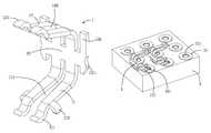
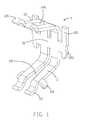
- FIG. 1is an isometric view of an electrical contact in accordance with the preferred embodiment of the present invention.
- FIG. 2is an isometric view of an electrical contact in accordance with the preferred embodiment of the present invention.
- FIG. 3is an assembly view of the contact and the PCB, showing the foot is connected with the pad of the PCB when the standing point is trapped in the via.
- an electrical connector 100 in accordance with the present inventionis used for electrically connecting an electronic package, such as a land grid array (LGA) central processing unit (CPU) (not shown), with a circuit substrate, such as a PCB 3 .
- the electrical connectorcomprises an insulative housing 2 with a plurality of contacts 1 received therein.
- the PCBcomprises a plurality of pads 31 and each pad 31 defines a via 311 in the middle thereof.
- the insulative housing 2is configured to a rectangular shape and comprises a top surface 21 and a bottom surface 22 opposite to the top surface 21 .
- the top surface 21defines a plurality of passageways 211 penetrate to the bottom surface 22 of the insulative housing 2 for receiving the contacts 1 and also defines a plurality of protruding portions 23 extending upwardly.
- the protruding portions 23are located between the two adjacent rows of passageways 211 .
- the protruding portions 23are used to support the CPU and the bottom surface 22 confronts the PCB 3 .
- the contact 1has a flat medial portion 10 , a pair of fasten portions 101 located on opposite ends of the medial portion 10 , a pair of first spring arms 11 extending downwardly and curvedly from the medial portion 10 and a pair of second spring arms 12 extending upwardly and curvedly from the medial portion 10 .
- the fasten portions 101extending upwardly from the body portion 10 and each has a barb 1011 .
- the pair of first spring arms 11are paralleled with each other and there is a first slot 110 between the two first spring arms 11
- the pair of second spring arms 12are paralleled with each other and there is a second slot 120 between the two second spring arms 12 .
- the first length of the first slot 110is equal to the length of the first spring arms 11 and the length of the second slot 120 is equal to the length of the second spring arms 12 .
- the first spring arms 11each includes a standing point 111 at bottom end thereof and the second spring arms 12 each defines an engaging portion 121 at top end thereof
- the foot 112 and the standing point 111are close to each other and extending in different directions.
- Each first spring arm 11has a distal end region to contact the conductive pad 31 .
- a width of the distal end regionis smaller than a diameter of the hole 311 .
- the auxiliary foot 112cooperates with the distal end region to form a bifurcate structure for preventing the distal end region of the spring arms 11 from being significantly trapped in the hole 311 .
- the standing point 111 and the foot 112are both projected out of the bottom surface 22 of the insulative housing 2 , the engaging portion 121 is projected out of the upper surface of the protruding portions 23 .
- the electrical connector 100is used to connect the CPU with the PCB 3 , the standing point 111 and the auxiliary foot 112 will not simultaneously trapped in the via 311 .
- the foot 112can ensure a good connection with the pad 31 of the PCB 3 .
Landscapes
- Coupling Device And Connection With Printed Circuit (AREA)
Abstract
Description
Claims (10)
Applications Claiming Priority (3)
| Application Number | Priority Date | Filing Date | Title |
|---|---|---|---|
| TW97215667 | 2008-09-01 | ||
| TW097215667UTWM358429U (en) | 2008-09-01 | 2008-09-01 | Electrical connector |
| TW97215667U | 2008-09-01 |
Publications (2)
| Publication Number | Publication Date |
|---|---|
| US20100055944A1 US20100055944A1 (en) | 2010-03-04 |
| US7972144B2true US7972144B2 (en) | 2011-07-05 |
Family
ID=41726113
Family Applications (1)
| Application Number | Title | Priority Date | Filing Date |
|---|---|---|---|
| US12/549,396Expired - Fee RelatedUS7972144B2 (en) | 2008-09-01 | 2009-08-28 | Electrical contact having additional mounting feet arranged to ensure reliable electrical connections with conductive pad around via of circuit board |
Country Status (2)
| Country | Link |
|---|---|
| US (1) | US7972144B2 (en) |
| TW (1) | TWM358429U (en) |
Cited By (12)
| Publication number | Priority date | Publication date | Assignee | Title |
|---|---|---|---|---|
| US20160141819A1 (en)* | 2014-11-14 | 2016-05-19 | Foxconn Interconnect Technology Limited | Electrical connector for use with cradle |
| US20160149325A1 (en)* | 2014-11-21 | 2016-05-26 | Yazaki Corporation | Substrate terminal and substrate with terminal |
| US9472904B2 (en)* | 2014-08-18 | 2016-10-18 | Amphenol Corporation | Discrete packaging adapter for connector |
| US20170365947A1 (en)* | 2016-06-16 | 2017-12-21 | Tyco Electronics Corporation | Interposer socket and connector assembly |
| US20180198226A1 (en)* | 2017-01-12 | 2018-07-12 | Lotes Co., Ltd | Electrical connector |
| US10276952B2 (en)* | 2017-04-28 | 2019-04-30 | Lotes Co., Ltd | Electrical connector and manufacturing method thereof |
| US10326225B2 (en)* | 2017-03-14 | 2019-06-18 | Lotes Co., Ltd | Electrical connector and terminal |
| US20190326692A1 (en)* | 2018-04-24 | 2019-10-24 | Lotes Co., Ltd | Electrical connector |
| US20190334272A1 (en)* | 2018-04-27 | 2019-10-31 | Fu Ding Precision Component (Shen Zhen) Co., Ltd. | Electrical contact |
| US10833441B2 (en)* | 2018-11-30 | 2020-11-10 | Fuding Precision Components (Shenzhen) Co., Ltd. | Electrical contact |
| US11050173B2 (en) | 2018-11-01 | 2021-06-29 | Foxconn (Kunshan) Computer Connector Co., Ltd. | Arrangement for lowering resistance on power delievery region of electrical connector |
| US20220384976A1 (en)* | 2021-05-31 | 2022-12-01 | Foxconn (Kunshan) Computer Connector Co., Ltd. | Electrical connector having a contact and a standoff secured to the contact |
Families Citing this family (4)
| Publication number | Priority date | Publication date | Assignee | Title |
|---|---|---|---|---|
| TWM380604U (en)* | 2009-11-12 | 2010-05-11 | Hon Hai Prec Ind Co Ltd | Electrical connector |
| US9172161B2 (en)* | 2012-12-12 | 2015-10-27 | Amphenol InterCon Systems, Inc. | Impedance controlled LGA interposer assembly |
| CN109119780B (en)* | 2017-06-26 | 2020-09-18 | 中航光电科技股份有限公司 | A conductive contact structure and electrical connector |
| CN110034430B (en)* | 2019-03-29 | 2021-05-25 | 番禺得意精密电子工业有限公司 | Electric connector and assembling method thereof |
Citations (6)
| Publication number | Priority date | Publication date | Assignee | Title |
|---|---|---|---|---|
| US20030082932A1 (en)* | 2001-11-01 | 2003-05-01 | Keyser Frank T. | Electrical connector assembly |
| US20050009380A1 (en)* | 2003-06-25 | 2005-01-13 | Brown John Bossert | Socket connector carrying flexible contacts |
| US20080050940A1 (en)* | 2006-08-22 | 2008-02-28 | Hon Hai Precision Ind. Co., Ltd. | Electrical connector with moveably contact |
| US20090035995A1 (en)* | 2007-08-03 | 2009-02-05 | Hon Hai Precision Ind. Co., Ltd. | Electrical connector with improved housing structure |
| US20090253287A1 (en)* | 2008-04-03 | 2009-10-08 | Hon Hai Precision Ind. Co., Ltd. | Electrical connector with LGA contacts |
| US20090325406A1 (en)* | 2008-06-27 | 2009-12-31 | Fujitsu Limited | Press-fit contact, connector, and connection structure of press-fit contact |
- 2008
- 2008-09-01TWTW097215667Upatent/TWM358429U/ennot_activeIP Right Cessation
- 2009
- 2009-08-28USUS12/549,396patent/US7972144B2/ennot_activeExpired - Fee Related
Patent Citations (6)
| Publication number | Priority date | Publication date | Assignee | Title |
|---|---|---|---|---|
| US20030082932A1 (en)* | 2001-11-01 | 2003-05-01 | Keyser Frank T. | Electrical connector assembly |
| US20050009380A1 (en)* | 2003-06-25 | 2005-01-13 | Brown John Bossert | Socket connector carrying flexible contacts |
| US20080050940A1 (en)* | 2006-08-22 | 2008-02-28 | Hon Hai Precision Ind. Co., Ltd. | Electrical connector with moveably contact |
| US20090035995A1 (en)* | 2007-08-03 | 2009-02-05 | Hon Hai Precision Ind. Co., Ltd. | Electrical connector with improved housing structure |
| US20090253287A1 (en)* | 2008-04-03 | 2009-10-08 | Hon Hai Precision Ind. Co., Ltd. | Electrical connector with LGA contacts |
| US20090325406A1 (en)* | 2008-06-27 | 2009-12-31 | Fujitsu Limited | Press-fit contact, connector, and connection structure of press-fit contact |
Cited By (21)
| Publication number | Priority date | Publication date | Assignee | Title |
|---|---|---|---|---|
| US10617027B2 (en) | 2014-08-18 | 2020-04-07 | Amphenol Corporation | Discrete packaging adapter for connector |
| US9472904B2 (en)* | 2014-08-18 | 2016-10-18 | Amphenol Corporation | Discrete packaging adapter for connector |
| US10039199B2 (en) | 2014-08-18 | 2018-07-31 | Amphenol Corporation | Discrete packaging adapter for connector |
| US9722375B2 (en)* | 2014-11-14 | 2017-08-01 | Foxconn Interconnect Technology Limited | Electrical connector for use with cradle |
| US20160141819A1 (en)* | 2014-11-14 | 2016-05-19 | Foxconn Interconnect Technology Limited | Electrical connector for use with cradle |
| US20160149325A1 (en)* | 2014-11-21 | 2016-05-26 | Yazaki Corporation | Substrate terminal and substrate with terminal |
| US9774118B2 (en)* | 2014-11-21 | 2017-09-26 | Yazaki Corporation | Substrate terminal and substrate with terminal |
| US20170365947A1 (en)* | 2016-06-16 | 2017-12-21 | Tyco Electronics Corporation | Interposer socket and connector assembly |
| US10079443B2 (en)* | 2016-06-16 | 2018-09-18 | Te Connectivity Corporation | Interposer socket and connector assembly |
| US20180198226A1 (en)* | 2017-01-12 | 2018-07-12 | Lotes Co., Ltd | Electrical connector |
| US10199756B2 (en)* | 2017-01-12 | 2019-02-05 | Lotes Co., Ltd | Electrical connector |
| US10326225B2 (en)* | 2017-03-14 | 2019-06-18 | Lotes Co., Ltd | Electrical connector and terminal |
| US10276952B2 (en)* | 2017-04-28 | 2019-04-30 | Lotes Co., Ltd | Electrical connector and manufacturing method thereof |
| US20190326692A1 (en)* | 2018-04-24 | 2019-10-24 | Lotes Co., Ltd | Electrical connector |
| US10658775B2 (en)* | 2018-04-24 | 2020-05-19 | Lotes Co., Ltd | Electrical connector directly connecting an electronic component to a circuit board |
| US20190334272A1 (en)* | 2018-04-27 | 2019-10-31 | Fu Ding Precision Component (Shen Zhen) Co., Ltd. | Electrical contact |
| US10797424B2 (en)* | 2018-04-27 | 2020-10-06 | Fuding Precision Components (Shenzhen) Co., Ltd. | Electrical contact |
| US11050173B2 (en) | 2018-11-01 | 2021-06-29 | Foxconn (Kunshan) Computer Connector Co., Ltd. | Arrangement for lowering resistance on power delievery region of electrical connector |
| US10833441B2 (en)* | 2018-11-30 | 2020-11-10 | Fuding Precision Components (Shenzhen) Co., Ltd. | Electrical contact |
| US20220384976A1 (en)* | 2021-05-31 | 2022-12-01 | Foxconn (Kunshan) Computer Connector Co., Ltd. | Electrical connector having a contact and a standoff secured to the contact |
| US12237606B2 (en)* | 2021-05-31 | 2025-02-25 | Foxconn (Kunshan) Computer Connector Co., Ltd. | Electrical connector having a contact and a standoff secured to the contact |
Also Published As
| Publication number | Publication date |
|---|---|
| TWM358429U (en) | 2009-06-01 |
| US20100055944A1 (en) | 2010-03-04 |
Similar Documents
| Publication | Publication Date | Title |
|---|---|---|
| US7972144B2 (en) | Electrical contact having additional mounting feet arranged to ensure reliable electrical connections with conductive pad around via of circuit board | |
| US7628661B2 (en) | Electrical contact | |
| US8888525B2 (en) | Electrical connector with dual arm contact | |
| US6881070B2 (en) | LGA connector and terminal thereof | |
| US7601036B2 (en) | Conductive contact for CPU socket connector | |
| US7553202B2 (en) | Electrical terminal | |
| US7780456B2 (en) | Electrical connector having reinforced contacts arrangement | |
| US7247062B1 (en) | Electrical contact used in an electrical socket | |
| US7878870B2 (en) | Electrical contact having improved soldering section of high compliance | |
| US8974236B2 (en) | Low profile electrical connector | |
| US8366452B2 (en) | Low profile socket connector with improved contacts | |
| US20080160841A1 (en) | Electrical contact used in an electrical socket | |
| US7628615B2 (en) | Electrical connector assembly having improved pick up cap | |
| US6887114B2 (en) | Electrical connector with high performance contacts | |
| US20090280689A1 (en) | Electrical contact with x-y offsets | |
| US7445461B1 (en) | Composite electrical contact with elastic wire contact part and separate rigid part | |
| US6976851B2 (en) | Electrical connector having minimal wiping terminals | |
| US9130321B2 (en) | Electrical connector having contact for either BGA or LGA package | |
| US7841859B2 (en) | Socket with solder pad | |
| CN201160146Y (en) | electrical connector terminal | |
| US8690585B2 (en) | Electrical connector for low profile application | |
| US7993145B1 (en) | Socket connector having electrical contact with low profile | |
| US7819671B2 (en) | Electrical connector having terminals with improved wiping capability | |
| US20030216086A1 (en) | Contact for electrical connector | |
| US20040266227A1 (en) | Electrical connector having electrical contacts with enlarged contact portions |
Legal Events
| Date | Code | Title | Description |
|---|---|---|---|
| AS | Assignment | Owner name:HON HAI PRECISION INDUSTRY CO., LTD.,TAIWAN Free format text:ASSIGNMENT OF ASSIGNORS INTEREST;ASSIGNORS:CHANG, CHUN-YI;LIU, JIA-HAU;REEL/FRAME:023159/0860 Effective date:20090810 Owner name:HON HAI PRECISION INDUSTRY CO., LTD., TAIWAN Free format text:ASSIGNMENT OF ASSIGNORS INTEREST;ASSIGNORS:CHANG, CHUN-YI;LIU, JIA-HAU;REEL/FRAME:023159/0860 Effective date:20090810 | |
| STCF | Information on status: patent grant | Free format text:PATENTED CASE | |
| FPAY | Fee payment | Year of fee payment:4 | |
| FEPP | Fee payment procedure | Free format text:MAINTENANCE FEE REMINDER MAILED (ORIGINAL EVENT CODE: REM.); ENTITY STATUS OF PATENT OWNER: LARGE ENTITY | |
| LAPS | Lapse for failure to pay maintenance fees | Free format text:PATENT EXPIRED FOR FAILURE TO PAY MAINTENANCE FEES (ORIGINAL EVENT CODE: EXP.); ENTITY STATUS OF PATENT OWNER: LARGE ENTITY | |
| STCH | Information on status: patent discontinuation | Free format text:PATENT EXPIRED DUE TO NONPAYMENT OF MAINTENANCE FEES UNDER 37 CFR 1.362 | |
| FP | Lapsed due to failure to pay maintenance fee | Effective date:20190705 |