US7972125B2 - Compressor having output adjustment assembly including piston actuation - Google Patents
Compressor having output adjustment assembly including piston actuationDownload PDFInfo
- Publication number
- US7972125B2 US7972125B2US12/474,868US47486809AUS7972125B2US 7972125 B2US7972125 B2US 7972125B2US 47486809 AUS47486809 AUS 47486809AUS 7972125 B2US7972125 B2US 7972125B2
- Authority
- US
- United States
- Prior art keywords
- compressor
- communication
- piston
- chamber
- passages
- Prior art date
- Legal status (The legal status is an assumption and is not a legal conclusion. Google has not performed a legal analysis and makes no representation as to the accuracy of the status listed.)
- Active, expires
Links
Images


Classifications
- F—MECHANICAL ENGINEERING; LIGHTING; HEATING; WEAPONS; BLASTING
- F04—POSITIVE - DISPLACEMENT MACHINES FOR LIQUIDS; PUMPS FOR LIQUIDS OR ELASTIC FLUIDS
- F04C—ROTARY-PISTON, OR OSCILLATING-PISTON, POSITIVE-DISPLACEMENT MACHINES FOR LIQUIDS; ROTARY-PISTON, OR OSCILLATING-PISTON, POSITIVE-DISPLACEMENT PUMPS
- F04C18/00—Rotary-piston pumps specially adapted for elastic fluids
- F04C18/02—Rotary-piston pumps specially adapted for elastic fluids of arcuate-engagement type, i.e. with circular translatory movement of co-operating members, each member having the same number of teeth or tooth-equivalents
- F04C18/0207—Rotary-piston pumps specially adapted for elastic fluids of arcuate-engagement type, i.e. with circular translatory movement of co-operating members, each member having the same number of teeth or tooth-equivalents both members having co-operating elements in spiral form
- F04C18/0215—Rotary-piston pumps specially adapted for elastic fluids of arcuate-engagement type, i.e. with circular translatory movement of co-operating members, each member having the same number of teeth or tooth-equivalents both members having co-operating elements in spiral form where only one member is moving
- F—MECHANICAL ENGINEERING; LIGHTING; HEATING; WEAPONS; BLASTING
- F04—POSITIVE - DISPLACEMENT MACHINES FOR LIQUIDS; PUMPS FOR LIQUIDS OR ELASTIC FLUIDS
- F04C—ROTARY-PISTON, OR OSCILLATING-PISTON, POSITIVE-DISPLACEMENT MACHINES FOR LIQUIDS; ROTARY-PISTON, OR OSCILLATING-PISTON, POSITIVE-DISPLACEMENT PUMPS
- F04C23/00—Combinations of two or more pumps, each being of rotary-piston or oscillating-piston type, specially adapted for elastic fluids; Pumping installations specially adapted for elastic fluids; Multi-stage pumps specially adapted for elastic fluids
- F04C23/008—Hermetic pumps
- F—MECHANICAL ENGINEERING; LIGHTING; HEATING; WEAPONS; BLASTING
- F04—POSITIVE - DISPLACEMENT MACHINES FOR LIQUIDS; PUMPS FOR LIQUIDS OR ELASTIC FLUIDS
- F04C—ROTARY-PISTON, OR OSCILLATING-PISTON, POSITIVE-DISPLACEMENT MACHINES FOR LIQUIDS; ROTARY-PISTON, OR OSCILLATING-PISTON, POSITIVE-DISPLACEMENT PUMPS
- F04C28/00—Control of, monitoring of, or safety arrangements for, pumps or pumping installations specially adapted for elastic fluids
- F04C28/10—Control of, monitoring of, or safety arrangements for, pumps or pumping installations specially adapted for elastic fluids characterised by changing the positions of the inlet or outlet openings with respect to the working chamber
- F04C28/16—Control of, monitoring of, or safety arrangements for, pumps or pumping installations specially adapted for elastic fluids characterised by changing the positions of the inlet or outlet openings with respect to the working chamber using lift valves
Definitions
- the present disclosurerelates to compressors, and more specifically to compressors having output adjustment assemblies.
- Scroll compressorsinclude a variety of output adjustment assemblies to vary operating capacity of a compressor.
- the output adjustment assembliesmay include fluid passages extending through a scroll member to selectively provide fluid communication between compression pockets and another pressure region of the compressor.
- a compressormay include a housing, a first scroll member, a second scroll member, and a compressor output adjustment assembly.
- the first scroll membermay be supported within the housing and may include a first end plate, a first spiral wrap extending from a first side of the first end plate, a first chamber located on a second side of the first end plate having first and second passages in communication therewith, a second chamber located on the second side of the first end plate having third and fourth passages in communication therewith, a first aperture extending through the first end plate and in communication with the first chamber, and a second aperture extending through the first end plate and in communication with the second chamber.
- the first and third passagesmay be in communication with a first pressure source and the second and fourth passages may be selectively in communication with a second pressure source.
- the second scroll membermay be supported within the housing and may include a second end plate having a second spiral wrap extending therefrom and meshingly engaged with the first spiral wrap to form a series of pockets.
- the first aperturemay be in communication with a first of the pockets operating at a first pressure to provide communication between the first pocket and the first chamber and the second aperture may be in communication with a second of the pockets different from the first pocket and operating at a second pressure to provide communication between the second pocket and the second chamber.
- the compressor output adjustment assemblymay include first and second pistons.
- the first pistonmay be located in the first chamber and displaceable between first and second positions and the second piston may be located in the second chamber and displaceable between first and second positions.
- the first pistonmay isolate the first aperture from communication with the first passage when in its second position and the second piston may isolate the second aperture from communication with the third passage when in its second position.
- the first pistonmay be in its second position when the second piston is in its second position.
- the compressormay additionally include a valve assembly operable in first and second modes and in communication with the second pressure source and the second and fourth passages.
- the valve assemblymay provide communication between the second and fourth passages and the second pressure source during the first operating mode.
- the valve assemblymay be in communication with a suction pressure region of the compressor and provide communication between the second and fourth passages and the suction pressure region and isolate the second and fourth passages from communication with the second pressure source during the second operating mode.
- the second pressure sourcemay include a discharge pressure region of the compressor.
- the first scroll membermay include a discharge passage in communication with the discharge pressure region and a fifth passage in communication with the discharge passage and the valve assembly.
- the first pistonmay be in its second position when the second passage is in communication with the second pressure source.
- the second pistonmay be in its second position when the fourth passage is in communication with the second pressure source.
- the first pistonmay be in its first position when the second passage is isolated from the second pressure source.
- the first pistonmay be in its first position when the second passage is in communication with a suction pressure region of the compressor.
- the compressormay additionally include a floating seal engaged with the first scroll member to form a third chamber.
- the first and second chambersmay be located axially between the third chamber and the pockets.
- the third chambermay be isolated from communication with the first and second chambers.
- Each of said first and second pressuresmay be at an intermediate pressure between an operating pressure of a suction pressure region of the compressor and an operating pressure of the second pressure source.
- the first and second chambersmay be rotationally spaced from one another.
- the compressor output adjustment assemblymay include a first biasing member engaged with the first piston to bias the first piston to its first position and a second biasing member engaged with the second piston to bias the second piston to its first position.
- the first and second aperturesmay be in communication with a suction pressure region of the compressor when the first piston is in its first position and the second piston is in its first position.
- the compressor output adjustment assemblymay include a vapor injection system in communication with the first and third passages.
- the vapor injection systemmay be in communication with the first and second apertures when the first piston is in its first position and the second piston is in its first position.
- the first pistonmay be axially displaceable between its first and second positions and the second piston may be axially displaceable between its first and second positions.
- FIG. 1is a section view of a compressor according to the present disclosure
- FIG. 3is a first section view of a non-orbiting scroll and compressor output adjustment assembly of the compressor of FIG. 1 ;
- FIG. 4is second section view of the non-orbiting scroll and compressor output adjustment assembly of FIG. 3 ;
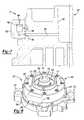
- FIG. 5is a perspective view of the non-orbiting scroll and compressor output adjustment assembly of FIG. 3 ;
- FIG. 6is a third section view of the non-orbiting scroll and compressor output adjustment assembly of FIG. 3 ;
- FIG. 7is a fourth section view of the non-orbiting scroll and compressor output adjustment assembly of FIG. 3 ;
- FIG. 8is a perspective view of an alternate non-orbiting scroll and compressor output adjustment assembly according to the present disclosure.
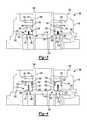
- FIG. 9is a first section view of the non-orbiting scroll and compressor output adjustment assembly of FIG. 8 ;
- FIG. 10is a second section view of the non-orbiting scroll and compressor output adjustment assembly of FIG. 8 ;
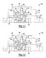
- FIG. 11is a third section view of the non-orbiting scroll and compressor output adjustment assembly of FIG. 8 ;
- FIG. 13is a fifth section view of the non-orbiting scroll and compressor output adjustment assembly of FIG. 8 ;
- FIG. 14is a sixth section view of the non-orbiting scroll and compressor output adjustment assembly of FIG. 8 ;
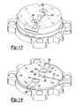
- FIG. 15is a plan view of the non-orbiting scroll of FIG. 8 ;
- FIG. 16is a schematic illustration of a first scroll orientation according to the present disclosure.
- FIG. 17is a schematic illustration of a second scroll orientation according to the present disclosure.
- FIG. 18is a schematic illustration of a third scroll orientation according to the present disclosure.
- FIG. 19is a schematic illustration of a fourth scroll orientation according to the present disclosure.
- FIG. 20is a first section view of an alternate non-orbiting scroll and compressor output adjustment assembly according to the present disclosure.
- a compressor 10is shown as a hermetic scroll refrigerant-compressor of the low-side type, i.e., where the motor and compressor are cooled by suction gas in the hermetic shell, as illustrated in the vertical section shown in FIG. 1 .
- compressor 10may include a hermetic shell assembly 12 , a main bearing housing assembly 14 , a motor assembly 16 , a compression mechanism 18 , a seal assembly 20 , a refrigerant discharge fitting 22 , a discharge valve assembly 24 , a suction gas inlet fitting 26 , and a modulation assembly 27 .
- Shell assembly 12may house main bearing housing assembly 14 , motor assembly 16 , and compression mechanism 18 .
- Shell assembly 12may generally form a compressor housing and may include a cylindrical shell 28 , an end cap 30 at the upper end thereof, a transversely extending partition 32 , and a base 34 at a lower end thereof. End cap 30 and partition 32 may generally define a discharge chamber 36 . Discharge chamber 36 may generally form a discharge muffler for compressor 10 . Refrigerant discharge fitting 22 may be attached to shell assembly 12 at opening 38 in end cap 30 . Discharge valve assembly 24 may be located within discharge fitting 22 and may generally prevent a reverse flow condition. Suction gas inlet fitting 26 may be attached to shell assembly 12 at opening 40 . Partition 32 may include a discharge passage 46 therethrough providing communication between compression mechanism 18 and discharge chamber 36 .
- Main bearing housing assembly 14may be affixed to shell 28 at a plurality of points in any desirable manner, such as staking.
- Main bearing housing assembly 14may include a main bearing housing 52 , a first bearing 54 disposed therein, bushings 55 , and fasteners 57 .
- Main bearing housing 52may include a central body portion 56 having a series of arms 58 extending radially outwardly therefrom.
- Central body portion 56may include first and second portions 60 , 62 having an opening 64 extending therethrough.
- Second portion 62may house first bearing 54 therein.
- First portion 60may define an annular flat thrust bearing surface 66 on an axial end surface thereof.
- Arm 58may include apertures 70 extending therethrough and receiving fasteners 57 .
- Motor assembly 16may generally include a motor stator 76 , a rotor 78 , and a drive shaft 80 . Windings 82 may pass through stator 76 . Motor stator 76 may be press fit into shell 28 . Drive shaft 80 may be rotatably driven by rotor 78 . Rotor 78 may be press fit on drive shaft 80 . Drive shaft 80 may include an eccentric crank pin 84 having a flat 86 thereon.
- Compression mechanism 18may generally include an orbiting scroll 104 and a non-orbiting scroll 106 .
- Orbiting scroll 104may include an end plate 108 having a spiral vane or wrap 110 on the upper surface thereof and an annular flat thrust surface 112 on the lower surface. Thrust surface 112 may interface with annular flat thrust bearing surface 66 on main bearing housing 52 .
- a cylindrical hub 114may project downwardly from thrust surface 112 and may have a drive bushing 116 rotatively disposed therein.
- Drive bushing 116may include an inner bore in which crank pin 84 is drivingly disposed.
- Crank pin flat 86may drivingly engage a flat surface in a portion of the inner bore of drive bushing 116 to provide a radially compliant driving arrangement.
- An Oldham coupling 117may be engaged with the orbiting and non-orbiting scrolls 104 , 106 to prevent relative rotation therebetween.
- non-orbiting scroll 106may include an end plate 118 having a spiral wrap 120 on a lower surface thereof, a discharge passage 119 extending through end plate 118 , and a series of radially outwardly extending flanged portions 121 .
- Spiral wrap 120may form a meshing engagement with wrap 110 of orbiting scroll 104 , thereby creating a series of pockets.
- the pockets created by spiral wraps 110 , 120may change throughout a compression cycle of compression mechanism 18 , as discussed below.
- End plate 118may include an annular recess 134 in the upper surface thereof defined by parallel coaxial inner and outer side walls 136 , 138 . Inner side wall 136 may form a discharge passage 139 . End plate 118 may further include first and second discrete recesses 140 , 142 . First and second recesses 140 , 142 may be located within annular recess 134 . Plugs 144 , 146 may be secured to end plate 118 at a top of first and second recesses 140 , 142 to form first and second chambers 145 , 147 isolated from annular recess 134 . An aperture 148 (seen in FIG. 2 ) may extend through end plate 118 providing communication between one of the pockets and annular recess 134 .
- a first passage 150may extend radially through end plate 118 from a first portion 152 (seen in FIG. 4 ) of first chamber 145 to an outer surface of non-orbiting scroll 106 and a second passage 154 (seen in FIG. 6 ) may extend radially through end plate 118 from a second portion 156 of first chamber 145 to an outer surface of non-orbiting scroll 106 .
- a third passage 158may extend radially through end plate 118 from a first portion 160 of second chamber 147 to an outer surface of non-orbiting scroll 106 and a fourth passage 162 may extend radially through end plate 118 from a second portion 164 of second chamber 147 to an outer surface of non-orbiting scroll 106 .
- First and third passages 150 , 158may be in communication with a suction pressure region of compressor 10 .
- a fifth passage 166( FIG. 7 ) may extend radially through end plate 118 from a discharge pressure region of compressor 10 to an outer surface of non-orbiting scroll 106 .
- fifth passage 166may extend from discharge passage 139 to an outer surface of non-orbiting scroll 106 .
- Second, fourth, and fifth passages 154 , 162 , 166may be in communication with modulation assembly 27 , as discussed below.
- a first set of ports 168 , 170may extend through end plate 118 and may be in communication with pockets operating at an intermediate pressure. Port 168 may extend into first portion 152 of first chamber 145 and port 170 may extend into first portion 160 of second chamber 147 .
- An additional set of ports 172 , 174may extend through end plate 118 and may be in communication with additional pockets operating at an intermediate pressure. Port 172 may extend into first chamber 145 and port 174 may extend into second chamber 147 .
- port 168may be located in one of the pockets located at least one hundred and eighty degrees radially inward from a starting point (A) of wrap 120 and port 170 may be located in one of the pockets located at least three hundred and sixty degrees radially inward from starting point (A) of wrap 120 .
- Port 168may be located radially inward relative to port 172 and port 170 may be located radially inward relative to port 174 .
- Ports 168 , 170may generally define the modulated capacity for compression mechanism 18 .
- Ports 172 , 174may form auxiliary ports for preventing compression in pockets radially outward from ports 168 , 170 when ports 168 , 170 , 172 , 174 are exposed to a suction pressure region of compressor 10 .
- Seal assembly 20may include a floating seal located within annular recess 134 .
- Seal assembly 20may be axially displaceable relative to shell assembly 12 and non-orbiting scroll 106 to provide for axial displacement of non-orbiting scroll 106 while maintaining a sealed engagement with partition 32 to isolate discharge and suction pressure regions of compressor 10 from one another. Pressure within annular recess 134 provided by aperture 148 may urge seal assembly 20 into engagement with partition 32 during normal compressor operation.
- Modulation assembly 27may include a valve assembly 176 , and first and second piston assemblies 178 , 180 .
- Valve assembly 176may include a solenoid valve having a housing 182 having a valve member 184 disposed therein.
- Housing 182may include first, second, and third passages 186 , 188 , 190 .
- First passage 186may be in communication with a suction pressure region of compressor 10
- second passage 188may be in communication with second and fourth passages 154 , 162 in end plate 118
- third passage 190may be in communication with fifth passage 166 in end plate 118 .
- Valve member 184may be displaceable between first and second positions.
- first and second passages 186 , 188may be in communication with one another and isolated from third passage 190 , placing second and fourth passages 154 , 162 in end plate 118 in communication with a suction pressure region of compressor 10 .
- second and third passages 188 , 190may be in communication with one another and isolated from first passage 186 , placing second and fourth passages 154 , 162 in end plate 118 in communication with a discharge pressure region of compressor 10 .
- First piston assembly 178may be located in first chamber 145 and may include a piston 192 , a seal 194 and a biasing member 196 .
- Second piston assembly 180may be located in second chamber 147 and may include a piston 198 , a seal 200 and a biasing member 202 .
- First and second pistons 192 , 198may be displaceable between first and second positions. More specifically, biasing members 196 , 202 may urge first and second pistons 192 , 198 into the first position ( FIG. 4 ) when valve member 184 is in the first position ( FIG. 6 ). When valve member 184 is in the second position ( FIG. 7 ), pistons 192 , 198 may be displaced to the second position ( FIG.
- Seal 194may prevent communication between first and second passages 150 , 154 when piston 192 is in both the first and second positions.
- Seal 200may prevent communication between third and fourth passages 158 , 162 when piston 198 is in both the first and second positions.
- piston 192may seal ports 168 , 172 from communication with first passage 150 and piston 198 may seal ports 170 , 174 from communication with third passage 158 .
- piston 192 , 198are in the first position, seen in FIG. 4 , piston 192 may be displaced away from ports 168 , 172 providing communication between ports 168 , 172 and first passage 150 and piston 198 may be displaced from ports 170 , 174 providing communication between ports 170 , 174 and third passage 158 .
- ports 168 , 170 , 172 , 174may each be in communication with a suction pressure region of compressor 10 , reducing an operating capacity of compressor 10 .
- Gasmay flow from the ports 168 , 170 , 172 , 174 to the suction pressure region of compressor 10 when pistons 192 , 198 are in the first position. Additionally, gas may flow from port 168 to port 172 when piston 192 is in the first position and gas may flow from port 170 to port 174 when piston 198 is in the first position.
- Non-orbiting scroll member 806may be generally similar to non-orbiting scroll 106 . Therefore, non-orbiting scroll 806 and the compressor adjustment assembly will not be described in detail with the understanding that the description above applies equally, with exceptions indicated below.
- Vapor injection system 700may be in communication with first and third passages 850 , 858 and with a vapor source from, for example, a heat exchanger or a flash tank in communication with the compressor.
- pistons 892 , 898When pistons 892 , 898 are in the first position, seen in FIG. 21 , piston 892 may be displaced away from ports 868 , 872 providing communication between ports 868 , 872 and first passage 850 and piston 898 may be displaced from ports 870 , 874 providing communication between ports 870 , 874 and third passage 858 . Therefore, when pistons 892 , 898 are in the first position, ports 868 , 870 , 872 , 874 may each be in communication with the vapor source from vapor injection system 700 , increasing an operating capacity of the compressor.
- Non-orbiting scroll 306may be incorporated into compressor 10 .
- Non-orbiting scroll 306may include first and second members 307 , 309 .
- First member 307may be fixed to second member 309 using fasteners 311 .
- First member 307may include a first end plate portion 317 and may include an annular recess 334 in the upper surface thereof defined by parallel coaxial side walls 336 , 338 .
- Side wall 336may for a discharge passage 339 .
- First end plate portion 317may include first and second discrete recesses 340 , 342 ( FIGS. 9 and 10 ) and third and fourth discrete recesses 344 , 346 ( FIGS. 11 and 12 ).
- An aperture 348(seen in FIGS. 11 and 12 ) may extend through first end plate portion 317 and into annular recess 334 .
- Second member 309may include a second end plate portion 318 having a spiral wrap 320 on a lower surface thereof, a discharge passage 319 extending through second end plate portion 318 , and a series of radially outwardly extending flanged portions 321 .
- Spiral wrap 320may form a meshing engagement with a wrap of an orbiting scroll similar to orbiting scroll 104 to create a series of pockets.
- Second end plate portion 318may further include first and second discrete recesses 341 , 343 ( FIGS. 9 and 10 ) and a central recess 349 ( FIGS. 11 and 12 ) having discharge passage 319 passing therethrough.
- first and second recesses 340 , 342 in first member 307may be aligned with first and second recesses 341 , 343 in second member 309 to form first and second chambers 345 , 347 .
- First and second chambers 345 , 347may be isolated from annular recess 334 .
- An aperture 351(seen in FIGS. 11 and 12 ) may extend through second end plate portion 318 and may be in communication with aperture 348 in first member 307 to provide pressure biasing for a floating seal assembly generally similar to that discussed above for seal assembly 20 .
- a first passage 350may extend radially through first end plate portion 317 from an outer surface of non-orbiting scroll 306 to first and second recesses 340 , 342 .
- a pair of second passages 358may extend radially through second end plate portion 318 from first recess 341 to an outer surface of non-orbiting scroll 306 and a pair of third passages 362 may extend radially through second end plate portion 318 from second recess 343 to an outer surface of non-orbiting scroll 306 .
- Second and third passages 358 , 362may be in communication with a suction pressure region.
- a fourth passage 366( FIGS.
- first and fourth passages 350 , 366may be in communication with modulation assembly 227 , as discussed below.
- Second end plate portion 318may further include first, second, third, fourth, fifth, and sixth modulation ports 368 , 370 , 371 , 372 , 373 , 374 , as well as first and second variable volume ratio (VVR) porting 406 , 408 .
- First, third, and fifth modulation ports 368 , 371 , 373may be in communication with first chamber 341 and second, fourth, and sixth modulation ports 370 , 372 , 374 may be in communication with second chamber 343 .
- First and second ports 368 , 370may generally define a modulated compressor capacity.
- Ports 368 , 370may each be located in one of the pockets located at least seven hundred and twenty degrees radially inward from a starting point (A′) of wrap 320 .
- Port 368may be located radially inward relative to ports 371 , 373 and port 370 may be located radially inward relative to ports 372 , 374 . Due to the greater inward location of ports 368 , 370 along wrap 320 , ports 371 , 372 , 373 , 374 may each form an auxiliary port for preventing compression in pockets radially outward from ports 368 , 370 when ports 368 , 370 , 371 , 372 , 373 , 374 are exposed to a suction pressure region.
- First and second VVR porting 406 , 408may be located radially inward relative to ports 368 , 370 , 371 , 372 , 373 , 374 and relative to aperture 351 .
- First and second VVR porting 406 , 408may be in communication with one of the pockets formed by wraps 310 , 320 ( FIGS. 16-19 ) and with central recess 349 . Therefore, first and second VVR porting 406 , 408 may be in communication with discharge passage 339 .
- Modulation assembly 227may include a valve assembly 376 and first and second piston assemblies 378 , 380 .
- Valve assembly 376may include a solenoid valve having a housing 382 having a valve member (not shown) disposed therein.
- First piston assembly 378may be located in first chamber 345 and may include a piston 392 , a seal 394 and a biasing member 396 .
- Second piston assembly 380may be located in second chamber 347 and may include a piston 398 , a seal 400 and a biasing member 402 .
- First and second pistons 392 , 398may be displaceable between first and second positions. More specifically, biasing members 396 , 402 may urge first and second pistons 392 , 398 into the first position ( FIG. 10 ) when valve assembly 376 vents recesses 340 , 342 .
- Valve assembly 376may selectively vent recesses 340 , 342 to a suction pressure region.
- Valve assembly 376may additionally be in communication with first passage 350 and fourth passage 366 . Valve assembly 376 may selectively provide communication between first passage 350 and a discharge pressure region via fourth passage 366 . When valve assembly 376 provides communication between first passage 350 and the discharge pressure region, pistons 392 , 398 may be displaced to the second position ( FIG. 9 ) by the discharge pressure provided by first passage 350 . Seal 394 may prevent communication between first passage 350 and the second passages 358 when piston 392 is in both the first and second positions. Seal 400 may prevent communication between the first passage 350 and third passages 362 when piston 398 is in both the first and second positions.
- piston 392may seal ports 368 , 371 , 373 from communication with second passages 358 and piston 398 may seal ports 370 , 372 , 374 from communication with third passages 362 .
- pistons 392 , 398are in the first position, seen in FIG. 10 , piston 392 may be displaced from ports 368 , 371 , 373 providing communication between ports 368 , 371 , 373 and second passages 358 and piston 398 may be displaced from ports 370 , 372 , 374 providing communication between ports 370 , 372 , 374 and third passages 362 .
- ports 368 , 370 , 371 , 372 , 373 , 374may each be in communication with a suction pressure region, reducing a compressor operating capacity. Additionally, when pistons 392 , 398 are in the first position, one or more of ports 368 , 370 , 371 , 372 , 373 , 374 may provide gas flow to another of ports 368 , 370 , 371 , 372 , 373 , 374 operating at a lower pressure.
- VVR assembly 500may selectively provide communication between VVR porting 406 , 408 and discharge passage 339 .
- VVR assembly 500may include first and second piston assemblies 502 , 504 .
- First piston assembly 502may include a piston 506 and a biasing member 508 such as a spring.
- Second piston assembly 504may include a piston 510 and a biasing member 512 such as a spring. Biasing members 508 , 512 may urge pistons 506 , 510 into a first position where pistons 506 , 510 are engaged with second end plate portion 318 to seal VVR porting 406 , 408 .
- VVR porting 406 , 408When pressure from VVR porting 406 , 408 exceeds a predetermined level, a force applied to pistons 506 , 510 by the gas in VVR porting 406 , 408 may exceed the force applied by biasing members 508 , 512 and pistons 506 , 510 may be displaced to a second position where VVR porting 406 , 408 is in communication with discharge passage 339 .
- first modulated capacity pockets 600 , 602may generally be defined as the radially outermost compression pockets that are disposed radially inwardly relative to port 368 and isolated from port 368 from the time the first modulated capacity pockets 600 , 602 are formed until the volume in the first modulated capacity pockets 600 , 602 is discharged through discharge passage 319 .
- the volume in the first modulated capacity pockets 600 , 602may be isolated from port 368 during a remainder of a compression cycle associated therewith.
- the volume of the first modulated capacity pockets 600 , 602may be at a maximum volume when orbiting scroll 304 is in the first position and may be continuously compressed until being discharged through discharge passage 319 .
- Spiral wrap 310 of orbiting scroll 304may abut an outer radial surface of spiral wrap 320 at a first location and may abut the inner radial surface of spiral wrap 320 at a second location generally opposite the first location when orbiting scroll 304 is in the first position.
- Port 368may extend at least twenty degrees along spiral wrap 310 in a rotational direction (R) of the drive shaft starting at a first angular position corresponding to the first location when orbiting scroll 304 is in the first position.
- Port 368may be sealed by spiral wrap 310 when orbiting scroll 304 is in the first position.
- a portion of port 370may be in communication with the first modulated capacity pocket 602 when orbiting scroll 304 is in the first position.
- orbiting scroll 304is illustrated in a second position where second modulated capacity pockets 604 , 606 are defined.
- the second modulated capacity pockets 604 , 606may generally be defined as the radially outermost compression pockets that are disposed radially inwardly relative to ports 368 , 370 and isolated from ports 368 , 370 from the time the orbiting scroll 304 is in the second position until the volume in the second modulated capacity pockets is discharged through discharge passage 319 .
- the second modulated capacity pockets 604 , 606may correspond to the first modulated capacity pockets 600 , 602 after compression resulting from orbiting scroll 304 travelling from the first position to the second position.
- the compression from the first position to the second positionmay correspond to approximately twenty degrees of rotation of the drive shaft.
- Spiral wrap 310 of orbiting scroll 304may abut an outer radial surface of spiral wrap 320 at a third location and may abut the an inner radial surface of spiral wrap 320 at a fourth location generally opposite the third location when orbiting scroll 304 is in the second position.
- Port 370may extend at least twenty degrees along spiral wrap 310 generally opposite a rotational direction (R) of the drive shaft starting at a second angular position corresponding to the fourth location when orbiting scroll 304 is in the second position.
- Port 370may be sealed by spiral wrap 310 when orbiting scroll 304 is in the second position.
- each of the pockets located radially outward from the first and second modulated capacity pockets 600 , 602 , 604 , 606may always be in communication with at least one of ports 368 , 370 , 371 , 372 , 373 , 374 .
- first VVR pockets 608 , 610may generally be defined as the radially innermost compression pockets that are disposed radially outwardly relative to VVR porting 406 and isolated from VVR porting 406 from the time a compression cycle is started until the first VVR pockets 608 , 610 are formed.
- the first VVR pockets 608 , 610may be in communication with VVR porting 406 during a remainder of a compression cycle.
- the volume of the first VVR pockets 608 , 610may be at a maximum volume when orbiting scroll 304 is in the third position and may be continuously compressed until being discharged through discharge passage 319 .
- Spiral wrap 310 of orbiting scroll 304may abut an outer radial surface of spiral wrap 320 at a fifth location and may abut the inner radial surface of spiral wrap 320 at a sixth location generally opposite the fifth location when orbiting scroll 304 is in the third position.
- VVR porting 406may extend at least twenty degrees along spiral wrap 310 in a rotational direction (R) of the drive shaft starting at an angular position corresponding to the fifth location when orbiting scroll 304 is in the third position.
- FIG. 19and orbiting scroll 304 is illustrated in a fourth position where second VVR pockets 612 , 614 are defined.
- the second VVR pockets 612 , 614may generally be defined as the radially innermost compression pockets that are disposed radially outwardly relative to VVR porting 408 and isolated from VVR porting 408 from the time a compression cycle is started until the second VVR pockets 612 , 614 are formed.
- the second VVR pockets 612 , 614may correspond to the first VVR pockets 608 , 610 after compression resulting from orbiting scroll 304 travelling from the third position to the fourth position.
- the compression from the third position to the fourth positionmay correspond to approximately forty degrees of rotation of the drive shaft.
- a portion of VVR porting 406may be in communication with the second VVR pockets 612 , 614 when orbiting scroll 304 is in the fourth position.
- Spiral wrap 310 of orbiting scroll 304may abut an outer radial surface of spiral wrap 320 at a seventh location and may abut the an inner radial surface of spiral wrap 320 at an eighth location generally opposite the seventh location when orbiting scroll 304 is in the fourth position.
- VVR porting 408may extend at least twenty degrees along spiral wrap 310 generally opposite a rotational direction (R) of the drive shaft starting at a fourth angular position corresponding to the eighth location when orbiting scroll 304 is in the fourth position.
Landscapes
- Engineering & Computer Science (AREA)
- Mechanical Engineering (AREA)
- General Engineering & Computer Science (AREA)
- Rotary Pumps (AREA)
- Applications Or Details Of Rotary Compressors (AREA)
Abstract
Description
Claims (20)
Priority Applications (3)
| Application Number | Priority Date | Filing Date | Title |
|---|---|---|---|
| US12/474,868US7972125B2 (en) | 2008-05-30 | 2009-05-29 | Compressor having output adjustment assembly including piston actuation |
| US13/165,306US8790098B2 (en) | 2008-05-30 | 2011-06-21 | Compressor having output adjustment assembly |
| US14/462,224US20140356211A1 (en) | 2008-05-30 | 2014-08-18 | Compressor having output adjustment assembly |
Applications Claiming Priority (2)
| Application Number | Priority Date | Filing Date | Title |
|---|---|---|---|
| US5737208P | 2008-05-30 | 2008-05-30 | |
| US12/474,868US7972125B2 (en) | 2008-05-30 | 2009-05-29 | Compressor having output adjustment assembly including piston actuation |
Related Child Applications (1)
| Application Number | Title | Priority Date | Filing Date |
|---|---|---|---|
| US13/165,306ContinuationUS8790098B2 (en) | 2008-05-30 | 2011-06-21 | Compressor having output adjustment assembly |
Publications (2)
| Publication Number | Publication Date |
|---|---|
| US20090297379A1 US20090297379A1 (en) | 2009-12-03 |
| US7972125B2true US7972125B2 (en) | 2011-07-05 |
Family
ID=41380098
Family Applications (3)
| Application Number | Title | Priority Date | Filing Date |
|---|---|---|---|
| US12/474,868Active2029-12-26US7972125B2 (en) | 2008-05-30 | 2009-05-29 | Compressor having output adjustment assembly including piston actuation |
| US13/165,306ActiveUS8790098B2 (en) | 2008-05-30 | 2011-06-21 | Compressor having output adjustment assembly |
| US14/462,224AbandonedUS20140356211A1 (en) | 2008-05-30 | 2014-08-18 | Compressor having output adjustment assembly |
Family Applications After (2)
| Application Number | Title | Priority Date | Filing Date |
|---|---|---|---|
| US13/165,306ActiveUS8790098B2 (en) | 2008-05-30 | 2011-06-21 | Compressor having output adjustment assembly |
| US14/462,224AbandonedUS20140356211A1 (en) | 2008-05-30 | 2014-08-18 | Compressor having output adjustment assembly |
Country Status (5)
| Country | Link |
|---|---|
| US (3) | US7972125B2 (en) |
| EP (1) | EP2307728B1 (en) |
| KR (1) | KR101192649B1 (en) |
| CN (2) | CN102089525B (en) |
| WO (1) | WO2009155099A2 (en) |
Cited By (35)
| Publication number | Priority date | Publication date | Assignee | Title |
|---|---|---|---|---|
| US20090110570A1 (en)* | 2007-10-30 | 2009-04-30 | Yong-Il Cho | Scroll compressor |
| US20090185935A1 (en)* | 2008-01-16 | 2009-07-23 | Seibel Stephen M | Scroll machine |
| US20090297378A1 (en)* | 2008-05-30 | 2009-12-03 | Stover Robert C | Compressor having capacity modulation system |
| US8568118B2 (en) | 2009-05-29 | 2013-10-29 | Emerson Climate Technologies, Inc. | Compressor having piston assembly |
| US8616014B2 (en) | 2009-05-29 | 2013-12-31 | Emerson Climate Technologies, Inc. | Compressor having capacity modulation or fluid injection systems |
| US8628316B2 (en) | 2008-05-30 | 2014-01-14 | Emerson Climate Technologies, Inc. | Compressor having capacity modulation system |
| US8790098B2 (en) | 2008-05-30 | 2014-07-29 | Emerson Climate Technologies, Inc. | Compressor having output adjustment assembly |
| US20150004039A1 (en)* | 2013-06-28 | 2015-01-01 | Emerson Climate Technologies, Inc. | Capacity-modulated scroll compressor |
| US20160032924A1 (en)* | 2014-08-04 | 2016-02-04 | Emerson Climate Technologies, Inc. | Capacity modulated scroll compressor |
| US9494157B2 (en) | 2012-11-30 | 2016-11-15 | Emerson Climate Technologies, Inc. | Compressor with capacity modulation and variable volume ratio |
| US9651043B2 (en) | 2012-11-15 | 2017-05-16 | Emerson Climate Technologies, Inc. | Compressor valve system and assembly |
| CN104813031B (en)* | 2012-11-15 | 2017-06-09 | 艾默生环境优化技术有限公司 | Compressor |
| US9777730B2 (en) | 2012-11-30 | 2017-10-03 | Emerson Climate Technologies, Inc. | Scroll compressor with variable volume ratio port in orbiting scroll |
| US9790940B2 (en) | 2015-03-19 | 2017-10-17 | Emerson Climate Technologies, Inc. | Variable volume ratio compressor |
| US9879674B2 (en) | 2009-04-07 | 2018-01-30 | Emerson Climate Technologies, Inc. | Compressor having capacity modulation assembly |
| US9989057B2 (en) | 2014-06-03 | 2018-06-05 | Emerson Climate Technologies, Inc. | Variable volume ratio scroll compressor |
| US10066622B2 (en) | 2015-10-29 | 2018-09-04 | Emerson Climate Technologies, Inc. | Compressor having capacity modulation system |
| US10378542B2 (en) | 2015-07-01 | 2019-08-13 | Emerson Climate Technologies, Inc. | Compressor with thermal protection system |
| US10378540B2 (en) | 2015-07-01 | 2019-08-13 | Emerson Climate Technologies, Inc. | Compressor with thermally-responsive modulation system |
| US10428817B2 (en) | 2016-03-18 | 2019-10-01 | Signify Holding B.V. | Cooling arrangement for cooling an apparatus |
| US10563891B2 (en) | 2017-01-26 | 2020-02-18 | Trane International Inc. | Variable displacement scroll compressor |
| US10753352B2 (en) | 2017-02-07 | 2020-08-25 | Emerson Climate Technologies, Inc. | Compressor discharge valve assembly |
| US10801495B2 (en) | 2016-09-08 | 2020-10-13 | Emerson Climate Technologies, Inc. | Oil flow through the bearings of a scroll compressor |
| US10890186B2 (en) | 2016-09-08 | 2021-01-12 | Emerson Climate Technologies, Inc. | Compressor |
| US10962008B2 (en) | 2017-12-15 | 2021-03-30 | Emerson Climate Technologies, Inc. | Variable volume ratio compressor |
| US10995753B2 (en) | 2018-05-17 | 2021-05-04 | Emerson Climate Technologies, Inc. | Compressor having capacity modulation assembly |
| US11022119B2 (en) | 2017-10-03 | 2021-06-01 | Emerson Climate Technologies, Inc. | Variable volume ratio compressor |
| US11656003B2 (en) | 2019-03-11 | 2023-05-23 | Emerson Climate Technologies, Inc. | Climate-control system having valve assembly |
| US11655813B2 (en) | 2021-07-29 | 2023-05-23 | Emerson Climate Technologies, Inc. | Compressor modulation system with multi-way valve |
| US11846287B1 (en) | 2022-08-11 | 2023-12-19 | Copeland Lp | Scroll compressor with center hub |
| US11965507B1 (en) | 2022-12-15 | 2024-04-23 | Copeland Lp | Compressor and valve assembly |
| US12163523B1 (en) | 2023-12-15 | 2024-12-10 | Copeland Lp | Compressor and valve assembly |
| US12173708B1 (en) | 2023-12-07 | 2024-12-24 | Copeland Lp | Heat pump systems with capacity modulation |
| US12259163B2 (en) | 2022-06-01 | 2025-03-25 | Copeland Lp | Climate-control system with thermal storage |
| US12416308B2 (en) | 2022-12-28 | 2025-09-16 | Copeland Lp | Compressor with shutdown assembly |
Families Citing this family (27)
| Publication number | Priority date | Publication date | Assignee | Title |
|---|---|---|---|---|
| KR101231059B1 (en)* | 2008-05-30 | 2013-02-06 | 에머슨 클리메이트 테크놀로지즈 인코퍼레이티드 | Compressor having capacity modulation system |
| WO2009155104A2 (en)* | 2008-05-30 | 2009-12-23 | Emerson Climate Technologies, Inc. | Compressor having capacity modulation system |
| CN102076963B (en)* | 2008-05-30 | 2013-09-18 | 艾默生环境优化技术有限公司 | A compressor with capacity adjustment system |
| US7976296B2 (en)* | 2008-12-03 | 2011-07-12 | Emerson Climate Technologies, Inc. | Scroll compressor having capacity modulation system |
| US8517703B2 (en)* | 2010-02-23 | 2013-08-27 | Emerson Climate Technologies, Inc. | Compressor including valve assembly |
| JP5832187B2 (en)* | 2011-07-22 | 2015-12-16 | 三菱重工業株式会社 | Scroll compressor |
| KR101278337B1 (en)* | 2011-10-04 | 2013-06-25 | 엘지전자 주식회사 | A scroll compressor and an air conditioner including the same |
| US20140219844A1 (en)* | 2013-02-06 | 2014-08-07 | Daimler Ag | Expansion device for use in a working medium circuit and method for operating an expansion device |
| KR102103362B1 (en)* | 2013-11-11 | 2020-04-22 | 엘지전자 주식회사 | A scroll compressor and an air conditioner including the same |
| KR102162738B1 (en)* | 2014-01-06 | 2020-10-07 | 엘지전자 주식회사 | Scroll compressor |
| KR102166427B1 (en)* | 2014-05-02 | 2020-10-15 | 엘지전자 주식회사 | Scroll compressor |
| US9739277B2 (en) | 2014-05-15 | 2017-08-22 | Emerson Climate Technologies, Inc. | Capacity-modulated scroll compressor |
| KR102241201B1 (en) | 2014-08-13 | 2021-04-16 | 엘지전자 주식회사 | Scroll compressor |
| KR102310647B1 (en) | 2014-12-12 | 2021-10-12 | 삼성전자주식회사 | Compressor |
| US10598180B2 (en) | 2015-07-01 | 2020-03-24 | Emerson Climate Technologies, Inc. | Compressor with thermally-responsive injector |
| CN205895597U (en)* | 2015-07-01 | 2017-01-18 | 艾默生环境优化技术有限公司 | Compressor with thermal response formula governing system |
| WO2017048830A1 (en) | 2015-09-14 | 2017-03-23 | Trane International Inc. | Intermediate discharge port for a compressor |
| KR101800261B1 (en)* | 2016-05-25 | 2017-11-22 | 엘지전자 주식회사 | Scroll compressor |
| CN108240337B (en)* | 2016-12-23 | 2020-10-09 | 艾默生环境优化技术(苏州)有限公司 | Valve assembly and scroll compressor |
| KR102403948B1 (en) | 2017-01-03 | 2022-05-31 | 엘지전자 주식회사 | Scroll compressor |
| KR102469601B1 (en)* | 2017-01-26 | 2022-11-22 | 엘지전자 주식회사 | Scroll compressor |
| KR102379671B1 (en)* | 2017-06-14 | 2022-03-28 | 엘지전자 주식회사 | Scroll compressor |
| KR102660782B1 (en) | 2022-04-20 | 2024-04-29 | 엘지전자 주식회사 | Scroll compressor |
| WO2024002348A1 (en)* | 2022-06-30 | 2024-01-04 | 谷轮环境科技(苏州)有限公司 | Fixed scroll assembly and scroll compressor |
| CN115638110A (en)* | 2022-11-04 | 2023-01-24 | 常熟英华特环境科技有限公司 | Pressure division cover and variable-pressure-ratio advanced exhaust structure in scroll compressor |
| KR102770848B1 (en) | 2023-01-12 | 2025-02-24 | 엘지전자 주식회사 | Scroll compressor |
| KR102817798B1 (en) | 2023-03-21 | 2025-06-09 | 엘지전자 주식회사 | Scroll compressor |
Citations (60)
| Publication number | Priority date | Publication date | Assignee | Title |
|---|---|---|---|---|
| US4382370A (en) | 1980-10-31 | 1983-05-10 | Hitachi, Ltd. | Refrigerating system using scroll type compressor |
| US4383805A (en) | 1980-11-03 | 1983-05-17 | The Trane Company | Gas compressor of the scroll type having delayed suction closing capacity modulation |
| US4497615A (en) | 1983-07-25 | 1985-02-05 | Copeland Corporation | Scroll-type machine |
| US4774816A (en) | 1986-12-04 | 1988-10-04 | Hitachi, Ltd. | Air conditioner or refrigerating plant incorporating scroll compressor |
| US4818195A (en) | 1986-02-26 | 1989-04-04 | Hitachi, Ltd. | Scroll compressor with valved port for each compression chamber |
| US4904164A (en) | 1987-06-30 | 1990-02-27 | Sanden Corporation | Scroll type compressor with variable displacement mechanism |
| US4940395A (en) | 1987-12-08 | 1990-07-10 | Sanden Corporation | Scroll type compressor with variable displacement mechanism |
| JPH0381588A (en) | 1989-08-23 | 1991-04-05 | Hitachi Ltd | Scroll compressor capacity control device |
| US5074760A (en) | 1988-08-12 | 1991-12-24 | Mitsubishi Jukogyo Kabushiki Kaisha | Scroll type compressor |
| US5169294A (en) | 1991-12-06 | 1992-12-08 | Carrier Corporation | Pressure ratio responsive unloader |
| USRE34148E (en) | 1985-06-18 | 1992-12-22 | Sanden Corporation | Scroll type compressor with variable displacement mechanism |
| US5192195A (en) | 1990-11-14 | 1993-03-09 | Mitsubishi Jukogyo Kabushiki Kaisha | Scroll type compressor with separate control block |
| US5193987A (en) | 1990-11-14 | 1993-03-16 | Mitsubishi Jukogyo Kabushiki Kaisha | Scroll type compressor |
| US5240389A (en) | 1991-07-26 | 1993-08-31 | Kabushiki Kaisha Toshiba | Scroll type compressor |
| US5356271A (en) | 1992-02-06 | 1994-10-18 | Mitsubishi Jukogyo Kabushiki Kaisha | Capacity control mechanism for scroll-type compressor |
| US5451146A (en) | 1992-04-01 | 1995-09-19 | Nippondenso Co., Ltd. | Scroll-type variable-capacity compressor with bypass valve |
| US5551846A (en) | 1995-12-01 | 1996-09-03 | Ford Motor Company | Scroll compressor capacity control valve |
| US5557897A (en) | 1992-02-20 | 1996-09-24 | Braas Gmbh | Fastening device for a roof sealing strip or the like |
| US5562426A (en) | 1994-06-03 | 1996-10-08 | Kabushiki Kaisha Toyoda Jidoshokki Seisakusho | Scroll type refrigerant compressor |
| US5639225A (en) | 1994-05-30 | 1997-06-17 | Nippondenso Co., Ltd. | Scroll type compressor |
| US5674058A (en) | 1994-06-08 | 1997-10-07 | Nippondenso Co., Ltd. | Scroll-type refrigerant compressor |
| US5678985A (en) | 1995-12-19 | 1997-10-21 | Copeland Corporation | Scroll machine with capacity modulation |
| US5855475A (en) | 1995-12-05 | 1999-01-05 | Matsushita Electric Industrial Co., Ltd. | Scroll compressor having bypass valves |
| US5885063A (en) | 1996-05-07 | 1999-03-23 | Matshushita Electric Industrial Co., Ltd. | Variable capacity scroll compressor |
| US5993171A (en) | 1996-06-25 | 1999-11-30 | Sanden Corporation | Scroll-type compressor with variable displacement mechanism |
| US5993177A (en) | 1996-05-21 | 1999-11-30 | Sanden Corporation | Scroll type compressor with improved variable displacement mechanism |
| JP2000161263A (en) | 1998-11-27 | 2000-06-13 | Mitsubishi Electric Corp | Capacity control scroll compressor |
| US6102671A (en) | 1997-09-04 | 2000-08-15 | Matsushita Electric Industrial Co., Ltd. | Scroll compressor |
| US6123517A (en) | 1997-11-24 | 2000-09-26 | Copeland Corporation | Scroll machine with capacity modulation |
| US6132179A (en) | 1997-09-09 | 2000-10-17 | Sanden Corporation | Scroll type compressor enabling a soft start with a simple structure |
| US6164940A (en) | 1998-09-11 | 2000-12-26 | Sanden Corporation | Scroll type compressor in which a soft starting mechanism is improved with a simple structure |
| US6176686B1 (en)* | 1999-02-19 | 2001-01-23 | Copeland Corporation | Scroll machine with capacity modulation |
| US6210120B1 (en) | 1999-03-19 | 2001-04-03 | Scroll Technologies | Low charge protection vent |
| US6213731B1 (en)* | 1999-09-21 | 2001-04-10 | Copeland Corporation | Compressor pulse width modulation |
| US6231316B1 (en) | 1998-07-01 | 2001-05-15 | Denso Corporation | Scroll-type variable-capacity compressor |
| US6273691B1 (en) | 1996-07-22 | 2001-08-14 | Matsushita Electric Industrial Co., Ltd. | Scroll gas compressor having asymmetric bypass holes |
| US6293767B1 (en)* | 2000-02-28 | 2001-09-25 | Copeland Corporation | Scroll machine with asymmetrical bleed hole |
| US6413058B1 (en) | 2000-11-21 | 2002-07-02 | Scroll Technologies | Variable capacity modulation for scroll compressor |
| US6412293B1 (en) | 2000-10-11 | 2002-07-02 | Copeland Corporation | Scroll machine with continuous capacity modulation |
| US6589035B1 (en) | 1996-10-04 | 2003-07-08 | Hitachi, Ltd. | Scroll compressor having a valved back-pressure chamber and a bypass for over-compression |
| US20040071571A1 (en) | 2001-06-29 | 2004-04-15 | Kazuhide Uchida | Scroll compressor |
| US20040146419A1 (en) | 2002-11-06 | 2004-07-29 | Masahiro Kawaguchi | Variable displacement mechanism for scroll type compressor |
| US20040197204A1 (en) | 2002-12-27 | 2004-10-07 | Akihito Yamanouchi | Variable displacement mechanism for scroll type compressor |
| US20050019177A1 (en) | 2003-07-26 | 2005-01-27 | Lg Electronics Inc. | Variable capacity scroll compressor |
| US20050053507A1 (en) | 2003-08-11 | 2005-03-10 | Makoto Takeuchi | Scroll compressor |
| US6884042B2 (en) | 2003-06-26 | 2005-04-26 | Scroll Technologies | Two-step self-modulating scroll compressor |
| US7229261B2 (en) | 2003-10-17 | 2007-06-12 | Matsushita Electric Industrial Co., Ltd. | Scroll compressor having an annular recess located outside an annular seal portion and another recess communicating with suction port of fixed scroll |
| JP2007154761A (en) | 2005-12-05 | 2007-06-21 | Daikin Ind Ltd | Scroll compressor |
| US20080159892A1 (en) | 2006-12-29 | 2008-07-03 | Industrial Technology Research Institute | Scroll type compressor |
| US20090071183A1 (en)* | 2007-07-02 | 2009-03-19 | Christopher Stover | Capacity modulated compressor |
| US7513753B2 (en)* | 2003-07-26 | 2009-04-07 | Lg Electronics Inc. | Variable capacity scroll compressor |
| US7547202B2 (en)* | 2006-12-08 | 2009-06-16 | Emerson Climate Technologies, Inc. | Scroll compressor with capacity modulation |
| US20090297377A1 (en)* | 2008-05-30 | 2009-12-03 | Stover Robert C | Compressor having capacity modulation system |
| US20090297378A1 (en)* | 2008-05-30 | 2009-12-03 | Stover Robert C | Compressor having capacity modulation system |
| US20090297380A1 (en)* | 2008-05-30 | 2009-12-03 | Stover Robert C | Compressor having capacity modulation system |
| US20100135836A1 (en)* | 2008-12-03 | 2010-06-03 | Stover Robert C | Scroll Compressor Having Capacity Modulation System |
| US20100158731A1 (en)* | 2008-05-30 | 2010-06-24 | Masao Akei | Compressor having capacity modulation system |
| US20100254841A1 (en)* | 2009-04-07 | 2010-10-07 | Masao Akei | Compressor having capacity modulation assembly |
| US20100300659A1 (en)* | 2009-05-29 | 2010-12-02 | Stover Robert C | Compressor Having Capacity Modulation Or Fluid Injection Systems |
| US20100303659A1 (en)* | 2009-05-29 | 2010-12-02 | Stover Robert C | Compressor having piston assembly |
Family Cites Families (62)
| Publication number | Priority date | Publication date | Assignee | Title |
|---|---|---|---|---|
| JPS58148290A (en) | 1982-02-26 | 1983-09-03 | Hitachi Ltd | Refrigerator with acroll compressor |
| US4431388A (en) | 1982-03-05 | 1984-02-14 | The Trane Company | Controlled suction unloading in a scroll compressor |
| JPS601395A (en) | 1983-06-17 | 1985-01-07 | Hitachi Ltd | scroll compressor |
| JPS6153486A (en) | 1984-08-22 | 1986-03-17 | Hitachi Ltd | scroll compressor |
| JPH0617676B2 (en) | 1985-02-15 | 1994-03-09 | 株式会社日立製作所 | Helium scroll compressor |
| US4767293A (en) | 1986-08-22 | 1988-08-30 | Copeland Corporation | Scroll-type machine with axially compliant mounting |
| JP2550612B2 (en)* | 1987-10-19 | 1996-11-06 | ダイキン工業株式会社 | Capacity control mechanism of scroll compressor |
| US4904165A (en) | 1988-08-02 | 1990-02-27 | Carrier Corporation | Muffler/check valve assembly for scroll compressor |
| JPH02196188A (en) | 1989-01-23 | 1990-08-02 | Hitachi Ltd | rotary compressor |
| US5156539A (en) | 1990-10-01 | 1992-10-20 | Copeland Corporation | Scroll machine with floating seal |
| CA2046548C (en) | 1990-10-01 | 2002-01-15 | Gary J. Anderson | Scroll machine with floating seal |
| JP2846106B2 (en)* | 1990-11-16 | 1999-01-13 | 三菱重工業株式会社 | Scroll compressor |
| JP3100452B2 (en) | 1992-02-18 | 2000-10-16 | サンデン株式会社 | Variable capacity scroll compressor |
| US5607288A (en) | 1993-11-29 | 1997-03-04 | Copeland Corporation | Scroll machine with reverse rotation protection |
| US5803716A (en) | 1993-11-29 | 1998-09-08 | Copeland Corporation | Scroll machine with reverse rotation protection |
| US5469716A (en) | 1994-05-03 | 1995-11-28 | Copeland Corporation | Scroll compressor with liquid injection |
| US5611674A (en) | 1995-06-07 | 1997-03-18 | Copeland Corporation | Capacity modulated scroll machine |
| US5741120A (en) | 1995-06-07 | 1998-04-21 | Copeland Corporation | Capacity modulated scroll machine |
| US5640854A (en) | 1995-06-07 | 1997-06-24 | Copeland Corporation | Scroll machine having liquid injection controlled by internal valve |
| KR0162228B1 (en) | 1995-11-03 | 1999-01-15 | 원하열 | Scroll compressor |
| JPH09151866A (en) | 1995-11-30 | 1997-06-10 | Sanyo Electric Co Ltd | Scroll compressor |
| US6077057A (en) | 1997-08-29 | 2000-06-20 | Scroll Technologies | Scroll compressor with back pressure seal protection during reverse rotation |
| US6185949B1 (en) | 1997-09-15 | 2001-02-13 | Mad Tech, L.L.C. | Digital control valve for refrigeration system |
| US6095765A (en)* | 1998-03-05 | 2000-08-01 | Carrier Corporation | Combined pressure ratio and pressure differential relief valve |
| JPH11264383A (en) | 1998-03-19 | 1999-09-28 | Hitachi Ltd | Positive displacement fluid machinery |
| US5996364A (en) | 1998-07-13 | 1999-12-07 | Carrier Corporation | Scroll compressor with unloader valve between economizer and suction |
| JP4639413B2 (en) | 1999-12-06 | 2011-02-23 | ダイキン工業株式会社 | Scroll compressor and air conditioner |
| JP2001329967A (en) | 2000-05-24 | 2001-11-30 | Toyota Industries Corp | Seal structure of scroll type compressor |
| US6350111B1 (en) | 2000-08-15 | 2002-02-26 | Copeland Corporation | Scroll machine with ported orbiting scroll member |
| JP2002089462A (en) | 2000-09-13 | 2002-03-27 | Toyota Industries Corp | Scroll type compressor and seal method for scroll type compressor |
| JP2002089468A (en) | 2000-09-14 | 2002-03-27 | Toyota Industries Corp | Scroll type compressor |
| JP2002089463A (en) | 2000-09-18 | 2002-03-27 | Toyota Industries Corp | Scroll type compressor |
| JP2002106483A (en) | 2000-09-29 | 2002-04-10 | Toyota Industries Corp | Scroll type compressor and sealing method therefor |
| JP2002106482A (en) | 2000-09-29 | 2002-04-10 | Toyota Industries Corp | Scroll type compressor and gas compression method |
| US6419457B1 (en)* | 2000-10-16 | 2002-07-16 | Copeland Corporation | Dual volume-ratio scroll machine |
| US6679683B2 (en) | 2000-10-16 | 2004-01-20 | Copeland Corporation | Dual volume-ratio scroll machine |
| US6457948B1 (en) | 2001-04-25 | 2002-10-01 | Copeland Corporation | Diagnostic system for a compressor |
| US6655172B2 (en) | 2002-01-24 | 2003-12-02 | Copeland Corporation | Scroll compressor with vapor injection |
| US6430959B1 (en) | 2002-02-11 | 2002-08-13 | Scroll Technologies | Economizer injection ports extending through scroll wrap |
| JP4310960B2 (en) | 2002-03-13 | 2009-08-12 | ダイキン工業株式会社 | Scroll type fluid machinery |
| JP2004190559A (en) | 2002-12-11 | 2004-07-08 | Daikin Ind Ltd | Positive displacement expander and fluid machine |
| US6821092B1 (en) | 2003-07-15 | 2004-11-23 | Copeland Corporation | Capacity modulated scroll compressor |
| JP3674625B2 (en) | 2003-09-08 | 2005-07-20 | ダイキン工業株式会社 | Rotary expander and fluid machine |
| US7278832B2 (en) | 2004-01-07 | 2007-10-09 | Carrier Corporation | Scroll compressor with enlarged vapor injection port area |
| US7156056B2 (en) | 2004-06-10 | 2007-01-02 | Achates Power, Llc | Two-cycle, opposed-piston internal combustion engine |
| AU2005288363A1 (en) | 2004-09-28 | 2006-04-06 | Daikin Industries, Ltd. | Slide member and fluid machine |
| KR100575704B1 (en) | 2004-11-11 | 2006-05-03 | 엘지전자 주식회사 | Variable Capacity of Scroll Compressor |
| US7228710B2 (en) | 2005-05-31 | 2007-06-12 | Scroll Technologies | Indentation to optimize vapor injection through ports extending through scroll wrap |
| CN1896518A (en)* | 2005-07-12 | 2007-01-17 | 乐金电子(天津)电器有限公司 | Vortex compressor and its vacuum preventer |
| US7815423B2 (en) | 2005-07-29 | 2010-10-19 | Emerson Climate Technologies, Inc. | Compressor with fluid injection system |
| US20070092390A1 (en) | 2005-10-26 | 2007-04-26 | Copeland Corporation | Scroll compressor |
| JP4920244B2 (en) | 2005-11-08 | 2012-04-18 | アネスト岩田株式会社 | Scroll fluid machinery |
| JP2007270697A (en) | 2006-03-31 | 2007-10-18 | Hitachi Ltd | Scroll fluid machinery |
| WO2007114582A1 (en) | 2006-04-06 | 2007-10-11 | Lg Electronics Inc. | Backflow preventing apparatus for compressor |
| US7674098B2 (en) | 2006-11-07 | 2010-03-09 | Scroll Technologies | Scroll compressor with vapor injection and unloader port |
| US7771178B2 (en) | 2006-12-22 | 2010-08-10 | Emerson Climate Technologies, Inc. | Vapor injection system for a scroll compressor |
| US8043078B2 (en) | 2007-09-11 | 2011-10-25 | Emerson Climate Technologies, Inc. | Compressor sealing arrangement |
| KR100916229B1 (en) | 2008-01-31 | 2009-09-08 | 엘지전자 주식회사 | Mode changer of scroll compressor |
| KR101231059B1 (en) | 2008-05-30 | 2013-02-06 | 에머슨 클리메이트 테크놀로지즈 인코퍼레이티드 | Compressor having capacity modulation system |
| US7972125B2 (en) | 2008-05-30 | 2011-07-05 | Emerson Climate Technologies, Inc. | Compressor having output adjustment assembly including piston actuation |
| JP2010106780A (en) | 2008-10-31 | 2010-05-13 | Hitachi Appliances Inc | Scroll compressor |
| US9127677B2 (en)* | 2012-11-30 | 2015-09-08 | Emerson Climate Technologies, Inc. | Compressor with capacity modulation and variable volume ratio |
- 2009
- 2009-05-29USUS12/474,868patent/US7972125B2/enactiveActive
- 2009-05-29KRKR1020107028609Apatent/KR101192649B1/enactiveActive
- 2009-05-29WOPCT/US2009/045647patent/WO2009155099A2/enactiveApplication Filing
- 2009-05-29EPEP09767410.5Apatent/EP2307728B1/enactiveActive
- 2009-05-29CNCN200980126965.2Apatent/CN102089525B/enactiveActive
- 2009-05-29CNCN201110324010.7Apatent/CN102418698B/enactiveActive
- 2011
- 2011-06-21USUS13/165,306patent/US8790098B2/enactiveActive
- 2014
- 2014-08-18USUS14/462,224patent/US20140356211A1/ennot_activeAbandoned
Patent Citations (68)
| Publication number | Priority date | Publication date | Assignee | Title |
|---|---|---|---|---|
| US4382370A (en) | 1980-10-31 | 1983-05-10 | Hitachi, Ltd. | Refrigerating system using scroll type compressor |
| US4383805A (en) | 1980-11-03 | 1983-05-17 | The Trane Company | Gas compressor of the scroll type having delayed suction closing capacity modulation |
| US4497615A (en) | 1983-07-25 | 1985-02-05 | Copeland Corporation | Scroll-type machine |
| USRE34148E (en) | 1985-06-18 | 1992-12-22 | Sanden Corporation | Scroll type compressor with variable displacement mechanism |
| US4818195A (en) | 1986-02-26 | 1989-04-04 | Hitachi, Ltd. | Scroll compressor with valved port for each compression chamber |
| US4774816A (en) | 1986-12-04 | 1988-10-04 | Hitachi, Ltd. | Air conditioner or refrigerating plant incorporating scroll compressor |
| US4904164A (en) | 1987-06-30 | 1990-02-27 | Sanden Corporation | Scroll type compressor with variable displacement mechanism |
| US4940395A (en) | 1987-12-08 | 1990-07-10 | Sanden Corporation | Scroll type compressor with variable displacement mechanism |
| US5074760A (en) | 1988-08-12 | 1991-12-24 | Mitsubishi Jukogyo Kabushiki Kaisha | Scroll type compressor |
| JPH0381588A (en) | 1989-08-23 | 1991-04-05 | Hitachi Ltd | Scroll compressor capacity control device |
| US5192195A (en) | 1990-11-14 | 1993-03-09 | Mitsubishi Jukogyo Kabushiki Kaisha | Scroll type compressor with separate control block |
| US5193987A (en) | 1990-11-14 | 1993-03-16 | Mitsubishi Jukogyo Kabushiki Kaisha | Scroll type compressor |
| US5240389A (en) | 1991-07-26 | 1993-08-31 | Kabushiki Kaisha Toshiba | Scroll type compressor |
| US5169294A (en) | 1991-12-06 | 1992-12-08 | Carrier Corporation | Pressure ratio responsive unloader |
| US5356271A (en) | 1992-02-06 | 1994-10-18 | Mitsubishi Jukogyo Kabushiki Kaisha | Capacity control mechanism for scroll-type compressor |
| US5557897A (en) | 1992-02-20 | 1996-09-24 | Braas Gmbh | Fastening device for a roof sealing strip or the like |
| US5577897A (en) | 1992-04-01 | 1996-11-26 | Nippondenso Co., Ltd. | Scroll-type variable-capacity compressor having two control valves |
| US5451146A (en) | 1992-04-01 | 1995-09-19 | Nippondenso Co., Ltd. | Scroll-type variable-capacity compressor with bypass valve |
| US5639225A (en) | 1994-05-30 | 1997-06-17 | Nippondenso Co., Ltd. | Scroll type compressor |
| US5562426A (en) | 1994-06-03 | 1996-10-08 | Kabushiki Kaisha Toyoda Jidoshokki Seisakusho | Scroll type refrigerant compressor |
| US5674058A (en) | 1994-06-08 | 1997-10-07 | Nippondenso Co., Ltd. | Scroll-type refrigerant compressor |
| US5551846A (en) | 1995-12-01 | 1996-09-03 | Ford Motor Company | Scroll compressor capacity control valve |
| US5855475A (en) | 1995-12-05 | 1999-01-05 | Matsushita Electric Industrial Co., Ltd. | Scroll compressor having bypass valves |
| US5678985A (en) | 1995-12-19 | 1997-10-21 | Copeland Corporation | Scroll machine with capacity modulation |
| US5885063A (en) | 1996-05-07 | 1999-03-23 | Matshushita Electric Industrial Co., Ltd. | Variable capacity scroll compressor |
| US5993177A (en) | 1996-05-21 | 1999-11-30 | Sanden Corporation | Scroll type compressor with improved variable displacement mechanism |
| US5993171A (en) | 1996-06-25 | 1999-11-30 | Sanden Corporation | Scroll-type compressor with variable displacement mechanism |
| US6273691B1 (en) | 1996-07-22 | 2001-08-14 | Matsushita Electric Industrial Co., Ltd. | Scroll gas compressor having asymmetric bypass holes |
| US7354259B2 (en) | 1996-10-04 | 2008-04-08 | Hitachi, Ltd. | Scroll compressor having a valved back pressure chamber and a bypass for overcompression |
| US6589035B1 (en) | 1996-10-04 | 2003-07-08 | Hitachi, Ltd. | Scroll compressor having a valved back-pressure chamber and a bypass for over-compression |
| US7137796B2 (en) | 1996-10-04 | 2006-11-21 | Hitachi, Ltd. | Scroll compressor |
| US7118358B2 (en) | 1996-10-04 | 2006-10-10 | Hitachi, Ltd. | Scroll compressor having a back-pressure chamber control valve |
| US6769888B2 (en) | 1996-10-04 | 2004-08-03 | Hitachi, Ltd. | Scroll compressor having a valved back pressure chamber and a bypass for overcompression |
| US6102671A (en) | 1997-09-04 | 2000-08-15 | Matsushita Electric Industrial Co., Ltd. | Scroll compressor |
| US6132179A (en) | 1997-09-09 | 2000-10-17 | Sanden Corporation | Scroll type compressor enabling a soft start with a simple structure |
| US6123517A (en) | 1997-11-24 | 2000-09-26 | Copeland Corporation | Scroll machine with capacity modulation |
| US6231316B1 (en) | 1998-07-01 | 2001-05-15 | Denso Corporation | Scroll-type variable-capacity compressor |
| US6164940A (en) | 1998-09-11 | 2000-12-26 | Sanden Corporation | Scroll type compressor in which a soft starting mechanism is improved with a simple structure |
| JP2000161263A (en) | 1998-11-27 | 2000-06-13 | Mitsubishi Electric Corp | Capacity control scroll compressor |
| US6176686B1 (en)* | 1999-02-19 | 2001-01-23 | Copeland Corporation | Scroll machine with capacity modulation |
| US6210120B1 (en) | 1999-03-19 | 2001-04-03 | Scroll Technologies | Low charge protection vent |
| US6213731B1 (en)* | 1999-09-21 | 2001-04-10 | Copeland Corporation | Compressor pulse width modulation |
| US6293767B1 (en)* | 2000-02-28 | 2001-09-25 | Copeland Corporation | Scroll machine with asymmetrical bleed hole |
| US6412293B1 (en) | 2000-10-11 | 2002-07-02 | Copeland Corporation | Scroll machine with continuous capacity modulation |
| US6413058B1 (en) | 2000-11-21 | 2002-07-02 | Scroll Technologies | Variable capacity modulation for scroll compressor |
| US20040071571A1 (en) | 2001-06-29 | 2004-04-15 | Kazuhide Uchida | Scroll compressor |
| US20040146419A1 (en) | 2002-11-06 | 2004-07-29 | Masahiro Kawaguchi | Variable displacement mechanism for scroll type compressor |
| US20040197204A1 (en) | 2002-12-27 | 2004-10-07 | Akihito Yamanouchi | Variable displacement mechanism for scroll type compressor |
| US6884042B2 (en) | 2003-06-26 | 2005-04-26 | Scroll Technologies | Two-step self-modulating scroll compressor |
| US6984114B2 (en) | 2003-06-26 | 2006-01-10 | Scroll Technologies | Two-step self-modulating scroll compressor |
| US20050019177A1 (en) | 2003-07-26 | 2005-01-27 | Lg Electronics Inc. | Variable capacity scroll compressor |
| US7513753B2 (en)* | 2003-07-26 | 2009-04-07 | Lg Electronics Inc. | Variable capacity scroll compressor |
| US7344365B2 (en) | 2003-08-11 | 2008-03-18 | Mitsubishi Heavy Industries, Ltd. | Scroll compressor with bypass holes communicating with an intake chamber |
| US20050053507A1 (en) | 2003-08-11 | 2005-03-10 | Makoto Takeuchi | Scroll compressor |
| US7229261B2 (en) | 2003-10-17 | 2007-06-12 | Matsushita Electric Industrial Co., Ltd. | Scroll compressor having an annular recess located outside an annular seal portion and another recess communicating with suction port of fixed scroll |
| JP2007154761A (en) | 2005-12-05 | 2007-06-21 | Daikin Ind Ltd | Scroll compressor |
| US7547202B2 (en)* | 2006-12-08 | 2009-06-16 | Emerson Climate Technologies, Inc. | Scroll compressor with capacity modulation |
| US20080159892A1 (en) | 2006-12-29 | 2008-07-03 | Industrial Technology Research Institute | Scroll type compressor |
| US20090071183A1 (en)* | 2007-07-02 | 2009-03-19 | Christopher Stover | Capacity modulated compressor |
| US20090297377A1 (en)* | 2008-05-30 | 2009-12-03 | Stover Robert C | Compressor having capacity modulation system |
| US20090297378A1 (en)* | 2008-05-30 | 2009-12-03 | Stover Robert C | Compressor having capacity modulation system |
| US20090297380A1 (en)* | 2008-05-30 | 2009-12-03 | Stover Robert C | Compressor having capacity modulation system |
| US20100158731A1 (en)* | 2008-05-30 | 2010-06-24 | Masao Akei | Compressor having capacity modulation system |
| US20110033328A1 (en)* | 2008-05-30 | 2011-02-10 | Emerson Climate Technologies, Inc. | Compressor having capacity modulation system |
| US20100135836A1 (en)* | 2008-12-03 | 2010-06-03 | Stover Robert C | Scroll Compressor Having Capacity Modulation System |
| US20100254841A1 (en)* | 2009-04-07 | 2010-10-07 | Masao Akei | Compressor having capacity modulation assembly |
| US20100300659A1 (en)* | 2009-05-29 | 2010-12-02 | Stover Robert C | Compressor Having Capacity Modulation Or Fluid Injection Systems |
| US20100303659A1 (en)* | 2009-05-29 | 2010-12-02 | Stover Robert C | Compressor having piston assembly |
Non-Patent Citations (10)
| Title |
|---|
| International Search Report dated Jan. 29, 2010 regarding International Application No. PCT/US2009/045647. |
| PCT/US2009/045630, filed May 29, 2009, Stover et al. |
| U.S. Appl. No. 12/474,633, filed May 29, 2009, Stover et al. |
| U.S. Appl. No. 12/474,736, filed May 29, 2009, Akei et al. |
| U.S. Appl. No. 12/474,806, filed May 29, 2009, Stover et al. |
| U.S. Appl. No. 12/474,954, filed May 29, 2009, Stover et al. |
| U.S. Appl. No. 12/629,432, filed Dec. 2, 2009, Stover et al. |
| U.S. Appl. No. 12/788,786, filed May 27, 2010, Stover et al. |
| U.S. Appl. No. 12/789,105, filed May 27, 2010, Stover et al. |
| Written Opinion of the International Searching Authority dated Jan. 29, 2010 regarding International Application No. PCT/US2009/045647. |
Cited By (56)
| Publication number | Priority date | Publication date | Assignee | Title |
|---|---|---|---|---|
| US8186970B2 (en)* | 2007-10-30 | 2012-05-29 | Lg Electronics Inc. | Scroll compressor including a fixed scroll and a orbiting scroll |
| US20090110570A1 (en)* | 2007-10-30 | 2009-04-30 | Yong-Il Cho | Scroll compressor |
| US20090185935A1 (en)* | 2008-01-16 | 2009-07-23 | Seibel Stephen M | Scroll machine |
| US8506271B2 (en) | 2008-01-16 | 2013-08-13 | Emerson Climate Technologies, Inc. | Scroll machine having axially biased scroll |
| US8025492B2 (en)* | 2008-01-16 | 2011-09-27 | Emerson Climate Technologies, Inc. | Scroll machine |
| US8313318B2 (en)* | 2008-05-30 | 2012-11-20 | Emerson Climate Technologies, Inc. | Compressor having capacity modulation system |
| US20110033328A1 (en)* | 2008-05-30 | 2011-02-10 | Emerson Climate Technologies, Inc. | Compressor having capacity modulation system |
| US8517704B2 (en) | 2008-05-30 | 2013-08-27 | Emerson Climate Technologies, Inc. | Compressor having capacity modulation system |
| US8529232B2 (en) | 2008-05-30 | 2013-09-10 | Emerson Climate Technologies, Inc. | Compressor having capacity modulation system |
| US20090297378A1 (en)* | 2008-05-30 | 2009-12-03 | Stover Robert C | Compressor having capacity modulation system |
| US8628316B2 (en) | 2008-05-30 | 2014-01-14 | Emerson Climate Technologies, Inc. | Compressor having capacity modulation system |
| US8790098B2 (en) | 2008-05-30 | 2014-07-29 | Emerson Climate Technologies, Inc. | Compressor having output adjustment assembly |
| US11635078B2 (en) | 2009-04-07 | 2023-04-25 | Emerson Climate Technologies, Inc. | Compressor having capacity modulation assembly |
| US10954940B2 (en) | 2009-04-07 | 2021-03-23 | Emerson Climate Technologies, Inc. | Compressor having capacity modulation assembly |
| US9879674B2 (en) | 2009-04-07 | 2018-01-30 | Emerson Climate Technologies, Inc. | Compressor having capacity modulation assembly |
| US8857200B2 (en) | 2009-05-29 | 2014-10-14 | Emerson Climate Technologies, Inc. | Compressor having capacity modulation or fluid injection systems |
| US8616014B2 (en) | 2009-05-29 | 2013-12-31 | Emerson Climate Technologies, Inc. | Compressor having capacity modulation or fluid injection systems |
| US8568118B2 (en) | 2009-05-29 | 2013-10-29 | Emerson Climate Technologies, Inc. | Compressor having piston assembly |
| US11434910B2 (en) | 2012-11-15 | 2022-09-06 | Emerson Climate Technologies, Inc. | Scroll compressor having hub plate |
| US9651043B2 (en) | 2012-11-15 | 2017-05-16 | Emerson Climate Technologies, Inc. | Compressor valve system and assembly |
| CN104813031B (en)* | 2012-11-15 | 2017-06-09 | 艾默生环境优化技术有限公司 | Compressor |
| US10495086B2 (en) | 2012-11-15 | 2019-12-03 | Emerson Climate Technologies, Inc. | Compressor valve system and assembly |
| US10094380B2 (en) | 2012-11-15 | 2018-10-09 | Emerson Climate Technologies, Inc. | Compressor |
| US10907633B2 (en) | 2012-11-15 | 2021-02-02 | Emerson Climate Technologies, Inc. | Scroll compressor having hub plate |
| US9777730B2 (en) | 2012-11-30 | 2017-10-03 | Emerson Climate Technologies, Inc. | Scroll compressor with variable volume ratio port in orbiting scroll |
| US9494157B2 (en) | 2012-11-30 | 2016-11-15 | Emerson Climate Technologies, Inc. | Compressor with capacity modulation and variable volume ratio |
| US20150004039A1 (en)* | 2013-06-28 | 2015-01-01 | Emerson Climate Technologies, Inc. | Capacity-modulated scroll compressor |
| US9989057B2 (en) | 2014-06-03 | 2018-06-05 | Emerson Climate Technologies, Inc. | Variable volume ratio scroll compressor |
| US20160032924A1 (en)* | 2014-08-04 | 2016-02-04 | Emerson Climate Technologies, Inc. | Capacity modulated scroll compressor |
| US9638191B2 (en)* | 2014-08-04 | 2017-05-02 | Emerson Climate Technologies, Inc. | Capacity modulated scroll compressor |
| US10323639B2 (en) | 2015-03-19 | 2019-06-18 | Emerson Climate Technologies, Inc. | Variable volume ratio compressor |
| US10323638B2 (en) | 2015-03-19 | 2019-06-18 | Emerson Climate Technologies, Inc. | Variable volume ratio compressor |
| US9790940B2 (en) | 2015-03-19 | 2017-10-17 | Emerson Climate Technologies, Inc. | Variable volume ratio compressor |
| US10378542B2 (en) | 2015-07-01 | 2019-08-13 | Emerson Climate Technologies, Inc. | Compressor with thermal protection system |
| US10378540B2 (en) | 2015-07-01 | 2019-08-13 | Emerson Climate Technologies, Inc. | Compressor with thermally-responsive modulation system |
| US10066622B2 (en) | 2015-10-29 | 2018-09-04 | Emerson Climate Technologies, Inc. | Compressor having capacity modulation system |
| US10087936B2 (en) | 2015-10-29 | 2018-10-02 | Emerson Climate Technologies, Inc. | Compressor having capacity modulation system |
| US10428817B2 (en) | 2016-03-18 | 2019-10-01 | Signify Holding B.V. | Cooling arrangement for cooling an apparatus |
| US10890186B2 (en) | 2016-09-08 | 2021-01-12 | Emerson Climate Technologies, Inc. | Compressor |
| US10801495B2 (en) | 2016-09-08 | 2020-10-13 | Emerson Climate Technologies, Inc. | Oil flow through the bearings of a scroll compressor |
| US10563891B2 (en) | 2017-01-26 | 2020-02-18 | Trane International Inc. | Variable displacement scroll compressor |
| US10753352B2 (en) | 2017-02-07 | 2020-08-25 | Emerson Climate Technologies, Inc. | Compressor discharge valve assembly |
| US11022119B2 (en) | 2017-10-03 | 2021-06-01 | Emerson Climate Technologies, Inc. | Variable volume ratio compressor |
| US10962008B2 (en) | 2017-12-15 | 2021-03-30 | Emerson Climate Technologies, Inc. | Variable volume ratio compressor |
| US11754072B2 (en) | 2018-05-17 | 2023-09-12 | Copeland Lp | Compressor having capacity modulation assembly |
| US10995753B2 (en) | 2018-05-17 | 2021-05-04 | Emerson Climate Technologies, Inc. | Compressor having capacity modulation assembly |
| US11656003B2 (en) | 2019-03-11 | 2023-05-23 | Emerson Climate Technologies, Inc. | Climate-control system having valve assembly |
| US11655813B2 (en) | 2021-07-29 | 2023-05-23 | Emerson Climate Technologies, Inc. | Compressor modulation system with multi-way valve |
| US11879460B2 (en) | 2021-07-29 | 2024-01-23 | Copeland Lp | Compressor modulation system with multi-way valve |
| US12259163B2 (en) | 2022-06-01 | 2025-03-25 | Copeland Lp | Climate-control system with thermal storage |
| US11846287B1 (en) | 2022-08-11 | 2023-12-19 | Copeland Lp | Scroll compressor with center hub |
| US12188470B2 (en) | 2022-08-11 | 2025-01-07 | Copeland Lp | Scroll compressor with center hub |
| US11965507B1 (en) | 2022-12-15 | 2024-04-23 | Copeland Lp | Compressor and valve assembly |
| US12416308B2 (en) | 2022-12-28 | 2025-09-16 | Copeland Lp | Compressor with shutdown assembly |
| US12173708B1 (en) | 2023-12-07 | 2024-12-24 | Copeland Lp | Heat pump systems with capacity modulation |
| US12163523B1 (en) | 2023-12-15 | 2024-12-10 | Copeland Lp | Compressor and valve assembly |
Also Published As
| Publication number | Publication date |
|---|---|
| CN102418698B (en) | 2014-12-10 |
| US20140356211A1 (en) | 2014-12-04 |
| US20090297379A1 (en) | 2009-12-03 |
| EP2307728A2 (en) | 2011-04-13 |
| CN102418698A (en) | 2012-04-18 |
| CN102089525B (en) | 2013-08-07 |
| WO2009155099A2 (en) | 2009-12-23 |
| CN102089525A (en) | 2011-06-08 |
| US20110250085A1 (en) | 2011-10-13 |
| US8790098B2 (en) | 2014-07-29 |
| EP2307728A4 (en) | 2015-07-22 |
| EP2307728B1 (en) | 2016-08-10 |
| KR20110009257A (en) | 2011-01-27 |
| KR101192649B1 (en) | 2012-10-19 |
| WO2009155099A3 (en) | 2010-03-25 |
Similar Documents
| Publication | Publication Date | Title |
|---|---|---|
| US7972125B2 (en) | Compressor having output adjustment assembly including piston actuation | |
| US7967582B2 (en) | Compressor having capacity modulation system | |
| US7967583B2 (en) | Compressor having capacity modulation system | |
| US11635078B2 (en) | Compressor having capacity modulation assembly | |
| US7976296B2 (en) | Scroll compressor having capacity modulation system | |
| US8517704B2 (en) | Compressor having capacity modulation system | |
| US8628316B2 (en) | Compressor having capacity modulation system | |
| US9494157B2 (en) | Compressor with capacity modulation and variable volume ratio | |
| US7988434B2 (en) | Compressor having capacity modulation system | |
| US8568118B2 (en) | Compressor having piston assembly |
Legal Events
| Date | Code | Title | Description |
|---|---|---|---|
| AS | Assignment | Owner name:EMERSON CLIMATE TECHNOLOGIES, INC., OHIO Free format text:ASSIGNMENT OF ASSIGNORS INTEREST;ASSIGNORS:STOVER, ROBERT C.;AKEI, MASAO;PEREVOZCHIKOV, MICHAEL M.;REEL/FRAME:023057/0470 Effective date:20090803 | |
| STCF | Information on status: patent grant | Free format text:PATENTED CASE | |
| CC | Certificate of correction | ||
| FPAY | Fee payment | Year of fee payment:4 | |
| MAFP | Maintenance fee payment | Free format text:PAYMENT OF MAINTENANCE FEE, 8TH YEAR, LARGE ENTITY (ORIGINAL EVENT CODE: M1552); ENTITY STATUS OF PATENT OWNER: LARGE ENTITY Year of fee payment:8 | |
| MAFP | Maintenance fee payment | Free format text:PAYMENT OF MAINTENANCE FEE, 12TH YEAR, LARGE ENTITY (ORIGINAL EVENT CODE: M1553); ENTITY STATUS OF PATENT OWNER: LARGE ENTITY Year of fee payment:12 | |
| AS | Assignment | Owner name:COPELAND LP, OHIO Free format text:ENTITY CONVERSION;ASSIGNOR:EMERSON CLIMATE TECHNOLOGIES, INC.;REEL/FRAME:064058/0724 Effective date:20230503 | |
| AS | Assignment | Owner name:WELLS FARGO BANK, NATIONAL ASSOCIATION, AS COLLATERAL AGENT, CALIFORNIA Free format text:SECURITY INTEREST;ASSIGNOR:COPELAND LP;REEL/FRAME:064280/0695 Effective date:20230531 Owner name:U.S. BANK TRUST COMPANY, NATIONAL ASSOCIATION, AS NOTES COLLATERAL AGENT, MINNESOTA Free format text:SECURITY INTEREST;ASSIGNOR:COPELAND LP;REEL/FRAME:064279/0327 Effective date:20230531 Owner name:ROYAL BANK OF CANADA, AS COLLATERAL AGENT, CANADA Free format text:SECURITY INTEREST;ASSIGNOR:COPELAND LP;REEL/FRAME:064278/0598 Effective date:20230531 | |
| AS | Assignment | Owner name:U.S. BANK TRUST COMPANY, NATIONAL ASSOCIATION, AS NOTES COLLATERAL AGENT, MINNESOTA Free format text:SECURITY INTEREST;ASSIGNOR:COPELAND LP;REEL/FRAME:068241/0264 Effective date:20240708 |