US7971969B2 - Printhead nozzle arrangement having ink ejecting actuators annularly arranged around ink ejection port - Google Patents
Printhead nozzle arrangement having ink ejecting actuators annularly arranged around ink ejection portDownload PDFInfo
- Publication number
- US7971969B2 US7971969B2US12/710,278US71027810AUS7971969B2US 7971969 B2US7971969 B2US 7971969B2US 71027810 AUS71027810 AUS 71027810AUS 7971969 B2US7971969 B2US 7971969B2
- Authority
- US
- United States
- Prior art keywords
- ink
- nozzle
- ejection port
- actuators
- printhead
- Prior art date
- Legal status (The legal status is an assumption and is not a legal conclusion. Google has not performed a legal analysis and makes no representation as to the accuracy of the status listed.)
- Expired - Fee Related
Links
Images


Classifications
- B—PERFORMING OPERATIONS; TRANSPORTING
- B41—PRINTING; LINING MACHINES; TYPEWRITERS; STAMPS
- B41J—TYPEWRITERS; SELECTIVE PRINTING MECHANISMS, i.e. MECHANISMS PRINTING OTHERWISE THAN FROM A FORME; CORRECTION OF TYPOGRAPHICAL ERRORS
- B41J2/00—Typewriters or selective printing mechanisms characterised by the printing or marking process for which they are designed
- B41J2/005—Typewriters or selective printing mechanisms characterised by the printing or marking process for which they are designed characterised by bringing liquid or particles selectively into contact with a printing material
- B41J2/01—Ink jet
- B41J2/135—Nozzles
- B41J2/14—Structure thereof only for on-demand ink jet heads
- B41J2/14427—Structure of ink jet print heads with thermal bend detached actuators
- B—PERFORMING OPERATIONS; TRANSPORTING
- B41—PRINTING; LINING MACHINES; TYPEWRITERS; STAMPS
- B41J—TYPEWRITERS; SELECTIVE PRINTING MECHANISMS, i.e. MECHANISMS PRINTING OTHERWISE THAN FROM A FORME; CORRECTION OF TYPOGRAPHICAL ERRORS
- B41J2/00—Typewriters or selective printing mechanisms characterised by the printing or marking process for which they are designed
- B41J2/005—Typewriters or selective printing mechanisms characterised by the printing or marking process for which they are designed characterised by bringing liquid or particles selectively into contact with a printing material
- B41J2/01—Ink jet
- B41J2/135—Nozzles
- B41J2/14—Structure thereof only for on-demand ink jet heads
- B41J2/1433—Structure of nozzle plates
- B—PERFORMING OPERATIONS; TRANSPORTING
- B41—PRINTING; LINING MACHINES; TYPEWRITERS; STAMPS
- B41J—TYPEWRITERS; SELECTIVE PRINTING MECHANISMS, i.e. MECHANISMS PRINTING OTHERWISE THAN FROM A FORME; CORRECTION OF TYPOGRAPHICAL ERRORS
- B41J2/00—Typewriters or selective printing mechanisms characterised by the printing or marking process for which they are designed
- B41J2/005—Typewriters or selective printing mechanisms characterised by the printing or marking process for which they are designed characterised by bringing liquid or particles selectively into contact with a printing material
- B41J2/01—Ink jet
- B41J2/135—Nozzles
- B41J2/16—Production of nozzles
- B41J2/1621—Manufacturing processes
- B41J2/1623—Manufacturing processes bonding and adhesion
- B—PERFORMING OPERATIONS; TRANSPORTING
- B41—PRINTING; LINING MACHINES; TYPEWRITERS; STAMPS
- B41J—TYPEWRITERS; SELECTIVE PRINTING MECHANISMS, i.e. MECHANISMS PRINTING OTHERWISE THAN FROM A FORME; CORRECTION OF TYPOGRAPHICAL ERRORS
- B41J2/00—Typewriters or selective printing mechanisms characterised by the printing or marking process for which they are designed
- B41J2/005—Typewriters or selective printing mechanisms characterised by the printing or marking process for which they are designed characterised by bringing liquid or particles selectively into contact with a printing material
- B41J2/01—Ink jet
- B41J2/135—Nozzles
- B41J2/16—Production of nozzles
- B41J2/1621—Manufacturing processes
- B41J2/1626—Manufacturing processes etching
- B41J2/1628—Manufacturing processes etching dry etching
- B—PERFORMING OPERATIONS; TRANSPORTING
- B41—PRINTING; LINING MACHINES; TYPEWRITERS; STAMPS
- B41J—TYPEWRITERS; SELECTIVE PRINTING MECHANISMS, i.e. MECHANISMS PRINTING OTHERWISE THAN FROM A FORME; CORRECTION OF TYPOGRAPHICAL ERRORS
- B41J2/00—Typewriters or selective printing mechanisms characterised by the printing or marking process for which they are designed
- B41J2/005—Typewriters or selective printing mechanisms characterised by the printing or marking process for which they are designed characterised by bringing liquid or particles selectively into contact with a printing material
- B41J2/01—Ink jet
- B41J2/135—Nozzles
- B41J2/16—Production of nozzles
- B41J2/1621—Manufacturing processes
- B41J2/1626—Manufacturing processes etching
- B41J2/1629—Manufacturing processes etching wet etching
- B—PERFORMING OPERATIONS; TRANSPORTING
- B41—PRINTING; LINING MACHINES; TYPEWRITERS; STAMPS
- B41J—TYPEWRITERS; SELECTIVE PRINTING MECHANISMS, i.e. MECHANISMS PRINTING OTHERWISE THAN FROM A FORME; CORRECTION OF TYPOGRAPHICAL ERRORS
- B41J2/00—Typewriters or selective printing mechanisms characterised by the printing or marking process for which they are designed
- B41J2/005—Typewriters or selective printing mechanisms characterised by the printing or marking process for which they are designed characterised by bringing liquid or particles selectively into contact with a printing material
- B41J2/01—Ink jet
- B41J2/135—Nozzles
- B41J2/16—Production of nozzles
- B41J2/1621—Manufacturing processes
- B41J2/1631—Manufacturing processes photolithography
- B—PERFORMING OPERATIONS; TRANSPORTING
- B41—PRINTING; LINING MACHINES; TYPEWRITERS; STAMPS
- B41J—TYPEWRITERS; SELECTIVE PRINTING MECHANISMS, i.e. MECHANISMS PRINTING OTHERWISE THAN FROM A FORME; CORRECTION OF TYPOGRAPHICAL ERRORS
- B41J2/00—Typewriters or selective printing mechanisms characterised by the printing or marking process for which they are designed
- B41J2/005—Typewriters or selective printing mechanisms characterised by the printing or marking process for which they are designed characterised by bringing liquid or particles selectively into contact with a printing material
- B41J2/01—Ink jet
- B41J2/135—Nozzles
- B41J2/16—Production of nozzles
- B41J2/1621—Manufacturing processes
- B41J2/1632—Manufacturing processes machining
- B—PERFORMING OPERATIONS; TRANSPORTING
- B41—PRINTING; LINING MACHINES; TYPEWRITERS; STAMPS
- B41J—TYPEWRITERS; SELECTIVE PRINTING MECHANISMS, i.e. MECHANISMS PRINTING OTHERWISE THAN FROM A FORME; CORRECTION OF TYPOGRAPHICAL ERRORS
- B41J2/00—Typewriters or selective printing mechanisms characterised by the printing or marking process for which they are designed
- B41J2/005—Typewriters or selective printing mechanisms characterised by the printing or marking process for which they are designed characterised by bringing liquid or particles selectively into contact with a printing material
- B41J2/01—Ink jet
- B41J2/135—Nozzles
- B41J2/16—Production of nozzles
- B41J2/1621—Manufacturing processes
- B41J2/1635—Manufacturing processes dividing the wafer into individual chips
- B—PERFORMING OPERATIONS; TRANSPORTING
- B41—PRINTING; LINING MACHINES; TYPEWRITERS; STAMPS
- B41J—TYPEWRITERS; SELECTIVE PRINTING MECHANISMS, i.e. MECHANISMS PRINTING OTHERWISE THAN FROM A FORME; CORRECTION OF TYPOGRAPHICAL ERRORS
- B41J2/00—Typewriters or selective printing mechanisms characterised by the printing or marking process for which they are designed
- B41J2/005—Typewriters or selective printing mechanisms characterised by the printing or marking process for which they are designed characterised by bringing liquid or particles selectively into contact with a printing material
- B41J2/01—Ink jet
- B41J2/135—Nozzles
- B41J2/16—Production of nozzles
- B41J2/1621—Manufacturing processes
- B41J2/1637—Manufacturing processes molding
- B41J2/1639—Manufacturing processes molding sacrificial molding
- B—PERFORMING OPERATIONS; TRANSPORTING
- B41—PRINTING; LINING MACHINES; TYPEWRITERS; STAMPS
- B41J—TYPEWRITERS; SELECTIVE PRINTING MECHANISMS, i.e. MECHANISMS PRINTING OTHERWISE THAN FROM A FORME; CORRECTION OF TYPOGRAPHICAL ERRORS
- B41J2/00—Typewriters or selective printing mechanisms characterised by the printing or marking process for which they are designed
- B41J2/005—Typewriters or selective printing mechanisms characterised by the printing or marking process for which they are designed characterised by bringing liquid or particles selectively into contact with a printing material
- B41J2/01—Ink jet
- B41J2/135—Nozzles
- B41J2/16—Production of nozzles
- B41J2/1621—Manufacturing processes
- B41J2/164—Manufacturing processes thin film formation
- B41J2/1642—Manufacturing processes thin film formation thin film formation by CVD [chemical vapor deposition]
- B—PERFORMING OPERATIONS; TRANSPORTING
- B41—PRINTING; LINING MACHINES; TYPEWRITERS; STAMPS
- B41J—TYPEWRITERS; SELECTIVE PRINTING MECHANISMS, i.e. MECHANISMS PRINTING OTHERWISE THAN FROM A FORME; CORRECTION OF TYPOGRAPHICAL ERRORS
- B41J2/00—Typewriters or selective printing mechanisms characterised by the printing or marking process for which they are designed
- B41J2/005—Typewriters or selective printing mechanisms characterised by the printing or marking process for which they are designed characterised by bringing liquid or particles selectively into contact with a printing material
- B41J2/01—Ink jet
- B41J2/135—Nozzles
- B41J2/16—Production of nozzles
- B41J2/1648—Production of print heads with thermal bend detached actuators
- B—PERFORMING OPERATIONS; TRANSPORTING
- B41—PRINTING; LINING MACHINES; TYPEWRITERS; STAMPS
- B41J—TYPEWRITERS; SELECTIVE PRINTING MECHANISMS, i.e. MECHANISMS PRINTING OTHERWISE THAN FROM A FORME; CORRECTION OF TYPOGRAPHICAL ERRORS
- B41J2/00—Typewriters or selective printing mechanisms characterised by the printing or marking process for which they are designed
- B41J2/005—Typewriters or selective printing mechanisms characterised by the printing or marking process for which they are designed characterised by bringing liquid or particles selectively into contact with a printing material
- B41J2/01—Ink jet
- B41J2/17—Ink jet characterised by ink handling
- B41J2/175—Ink supply systems ; Circuit parts therefor
- B41J2/17596—Ink pumps, ink valves
- B—PERFORMING OPERATIONS; TRANSPORTING
- B41—PRINTING; LINING MACHINES; TYPEWRITERS; STAMPS
- B41J—TYPEWRITERS; SELECTIVE PRINTING MECHANISMS, i.e. MECHANISMS PRINTING OTHERWISE THAN FROM A FORME; CORRECTION OF TYPOGRAPHICAL ERRORS
- B41J2/00—Typewriters or selective printing mechanisms characterised by the printing or marking process for which they are designed
- B41J2/005—Typewriters or selective printing mechanisms characterised by the printing or marking process for which they are designed characterised by bringing liquid or particles selectively into contact with a printing material
- B41J2/01—Ink jet
- B41J2/015—Ink jet characterised by the jet generation process
- B41J2/04—Ink jet characterised by the jet generation process generating single droplets or particles on demand
- B41J2002/041—Electromagnetic transducer
- B—PERFORMING OPERATIONS; TRANSPORTING
- B41—PRINTING; LINING MACHINES; TYPEWRITERS; STAMPS
- B41J—TYPEWRITERS; SELECTIVE PRINTING MECHANISMS, i.e. MECHANISMS PRINTING OTHERWISE THAN FROM A FORME; CORRECTION OF TYPOGRAPHICAL ERRORS
- B41J2/00—Typewriters or selective printing mechanisms characterised by the printing or marking process for which they are designed
- B41J2/005—Typewriters or selective printing mechanisms characterised by the printing or marking process for which they are designed characterised by bringing liquid or particles selectively into contact with a printing material
- B41J2/01—Ink jet
- B41J2/135—Nozzles
- B41J2/14—Structure thereof only for on-demand ink jet heads
- B41J2002/14346—Ejection by pressure produced by thermal deformation of ink chamber, e.g. buckling
- B—PERFORMING OPERATIONS; TRANSPORTING
- B41—PRINTING; LINING MACHINES; TYPEWRITERS; STAMPS
- B41J—TYPEWRITERS; SELECTIVE PRINTING MECHANISMS, i.e. MECHANISMS PRINTING OTHERWISE THAN FROM A FORME; CORRECTION OF TYPOGRAPHICAL ERRORS
- B41J2/00—Typewriters or selective printing mechanisms characterised by the printing or marking process for which they are designed
- B41J2/005—Typewriters or selective printing mechanisms characterised by the printing or marking process for which they are designed characterised by bringing liquid or particles selectively into contact with a printing material
- B41J2/01—Ink jet
- B41J2/135—Nozzles
- B41J2/14—Structure thereof only for on-demand ink jet heads
- B41J2/14427—Structure of ink jet print heads with thermal bend detached actuators
- B41J2002/14435—Moving nozzle made of thermal bend detached actuator
- B—PERFORMING OPERATIONS; TRANSPORTING
- B41—PRINTING; LINING MACHINES; TYPEWRITERS; STAMPS
- B41J—TYPEWRITERS; SELECTIVE PRINTING MECHANISMS, i.e. MECHANISMS PRINTING OTHERWISE THAN FROM A FORME; CORRECTION OF TYPOGRAPHICAL ERRORS
- B41J2/00—Typewriters or selective printing mechanisms characterised by the printing or marking process for which they are designed
- B41J2/005—Typewriters or selective printing mechanisms characterised by the printing or marking process for which they are designed characterised by bringing liquid or particles selectively into contact with a printing material
- B41J2/01—Ink jet
- B41J2/135—Nozzles
- B41J2/14—Structure thereof only for on-demand ink jet heads
- B41J2002/14475—Structure thereof only for on-demand ink jet heads characterised by nozzle shapes or number of orifices per chamber
- B—PERFORMING OPERATIONS; TRANSPORTING
- B41—PRINTING; LINING MACHINES; TYPEWRITERS; STAMPS
- B41J—TYPEWRITERS; SELECTIVE PRINTING MECHANISMS, i.e. MECHANISMS PRINTING OTHERWISE THAN FROM A FORME; CORRECTION OF TYPOGRAPHICAL ERRORS
- B41J2202/00—Embodiments of or processes related to ink-jet or thermal heads
- B41J2202/01—Embodiments of or processes related to ink-jet heads
- B41J2202/15—Moving nozzle or nozzle plate
- Y—GENERAL TAGGING OF NEW TECHNOLOGICAL DEVELOPMENTS; GENERAL TAGGING OF CROSS-SECTIONAL TECHNOLOGIES SPANNING OVER SEVERAL SECTIONS OF THE IPC; TECHNICAL SUBJECTS COVERED BY FORMER USPC CROSS-REFERENCE ART COLLECTIONS [XRACs] AND DIGESTS
- Y10—TECHNICAL SUBJECTS COVERED BY FORMER USPC
- Y10T—TECHNICAL SUBJECTS COVERED BY FORMER US CLASSIFICATION
- Y10T29/00—Metal working
- Y10T29/49—Method of mechanical manufacture
- Y10T29/49401—Fluid pattern dispersing device making, e.g., ink jet
Definitions
- the present inventionrelates to the field of inkjet printing and, in particular, discloses an inverted radial back-curling thermoelastic ink jet printing mechanism.
- printershave a variety of methods for marking the print media with a relevant marking media.
- Commonly used forms of printinginclude offset printing, laser printing and copying devices, dot matrix type impact printers, thermal paper printers, film recorders, thermal wax printers, dye sublimation printers and ink jet printers both of the drop on demand and continuous flow type.
- Each type of printerhas its own advantages and problems when considering cost, speed, quality, reliability, simplicity of construction and operation etc.
- Ink Jet printersthemselves come in many different forms.
- the utilization of a continuous stream of ink in ink jet printingappears to date back to at least 1929 wherein U.S. Pat. No. 1,941,001 by Hansell discloses a simple form of continuous stream electro-static ink jet printing.
- U.S. Pat. No. 3,596,275 by Sweetalso discloses a process of a continuous ink jet printing including a step wherein the ink jet stream is modulated by a high frequency electro-static field so as to cause drop separation. This technique is still utilized by several manufacturers including Elmjet and Scitex (see also U.S. Pat. No. 3,373,437 by Sweet et al).
- Piezoelectric ink jet printersare also one form of commonly utilized ink jet printing device. Piezoelectric systems are disclosed by Kyser et. al. in U.S. Pat. No. 3,946,398 (1970) which utilizes a diaphragm mode of operation, by Zolten in U.S. Pat. No. 3,683,212 (1970) which discloses a squeeze mode form of operation of a piezoelectric crystal, Stemme in U.S. Pat. No. 3,747,120 (1972) which discloses a bend mode of piezoelectric operation, Howkins in U.S. Pat. No. 4,459,601 which discloses a piezoelectric push mode actuation of the ink jet stream and Fischbeck in U.S. Pat. No. 4,584,590 which discloses a shear mode type of piezoelectric transducer element.
- the ink jet printing techniquesinclude those disclosed by Endo et al in GB 2007162 (1979) and Vaught et al in U.S. Pat. No. 4,490,728. Both the aforementioned references disclose ink jet printing techniques which rely on the activation of an electrothermal actuator which results in the creation of a bubble in a constricted space, such as a nozzle, which thereby causes the ejection of ink from an aperture connected to the confined space onto a relevant print media.
- Printing devices utilizing the electro-thermal actuatorare manufactured by manufacturers such as Canon and Hewlett Packard.
- a printing technologyshould have a number of desirable attributes. These include inexpensive construction and operation, high speed operation, safe and continuous long term operation etc. Each technology may have its own advantages and disadvantages in the areas of cost, speed, quality, reliability, power usage, simplicity of construction and operation, durability and consumables.
- aA printhead for an inkjet printerincludes a wafer defining a plurality of nozzle chambers and a plurality of ink supply channel in fluid communication with the plurality of nozzle chambers for supplying the plurality of nozzle chambers with ink; an ink ejection port associated with each nozzle chamber; and a plurality of actuators associated with each nozzle chamber, the plurality of actuators each including a petal formation.
- a plurality of petal formationsare arranged around an ink ejection port of each nozzle chamber to annularly surround the ink ejection port.
- Each actuatoris operable to displace a respective petal formation into the nozzle chamber.
- FIGS. 1-3are schematic sectional views illustrating the operational principles of the preferred embodiment
- FIG. 4( a ) and FIG. 4( b )are again schematic sections illustrating the operational principles of the thermal actuator device
- FIG. 5is a side perspective view, partly in section, of a single nozzle arrangement constructed in accordance with the preferred embodiments
- FIGS. 6-13are side perspective views, partly in section, illustrating the manufacturing steps of the preferred embodiments.
- FIG. 14illustrates an array of ink jet nozzles formed in accordance with the manufacturing procedures of the preferred embodiment
- FIG. 15provides a legend of the materials indicated in FIGS. 16 to 23 ;
- FIG. 16 to FIG. 23illustrate sectional views of the manufacturing steps in one form of construction of a nozzle arrangement in accordance with the invention.
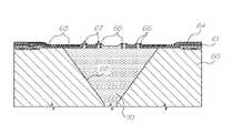
- inkis ejected out of a nozzle chamber via an ink ejection port using a series of radially positioned thermal actuator devices that are arranged about the ink ejection port and are activated to pressurize the ink within the nozzle chamber thereby causing the ejection of ink through the ejection port.
- FIG. 1illustrates a single nozzle arrangement 1 in its quiescent state.
- the arrangement 1includes a nozzle chamber 2 which is normally filled with ink so as to form a meniscus 3 in an ink ejection port 4 .
- the nozzle chamber 2is formed within a wafer 5 .
- the nozzle chamber 2is supplied with ink via an ink supply channel 6 which is etched through the wafer 5 with a highly isotropic plasma etching system.
- a suitable etchercan be the Advance Silicon Etch (ASE) system available from Surface Technology Systems of the United Kingdom.
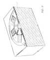
- a top of the nozzle arrangement 1includes a series of radially positioned actuators 8 , 9 .
- These actuatorscomprise a polytetrafluoroethylene (PTFE) layer and an internal serpentine copper core 17 .
- PTFEpolytetrafluoroethylene
- the surrounding PTFEexpands rapidly resulting in a generally downward movement of the actuators 8 , 9 .
- a currentis passed through the actuators 8 , 9 which results in them bending generally downwards as illustrated in FIG. 2 .
- the downward bending movement of the actuators 8 , 9results in a substantial increase in pressure within the nozzle chamber 2 .
- the increase in pressure in the nozzle chamber 2results in an expansion of the meniscus 3 as illustrated in FIG. 2 .
- the actuators 8 , 9are activated only briefly and subsequently deactivated. Consequently, the situation is as illustrated in FIG. 3 with the actuators 8 , 9 returning to their original positions. This results in a general inflow of ink back into the nozzle chamber 2 and a necking and breaking of the meniscus 3 resulting in the ejection of a drop 12 .
- the necking and breaking of the meniscus 3is a consequence of the forward momentum of the ink associated with drop 12 and the backward pressure experienced as a result of the return of the actuators 8 , 9 to their original positions.
- the return of the actuators 8 , 9also results in a general inflow of ink from the channel 6 as a result of surface tension effects and, eventually, the state returns to the quiescent position as illustrated in FIG. 1 .
- FIGS. 4( a ) and 4 ( b )illustrate the principle of operation of the thermal actuator.
- the thermal actuatoris preferably constructed from a material 14 having a high coefficient of thermal expansion.
- a series of heater elements 15which can be a series of conductive elements designed to carry a current.
- the conductive elements 15are heated by passing a current through the elements 15 with the heating resulting in a general increase in temperature in the area around the heating elements 15 .
- the position of the elements 15is such that uneven heating of the material 14 occurs.
- the uneven increase in temperaturecauses a corresponding uneven expansion of the material 14 .
- the PTFEis bent generally in the direction shown.
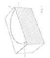
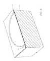
- FIG. 5there is illustrated a side perspective view of one embodiment of a nozzle arrangement constructed in accordance with the principles previously outlined.
- the nozzle chamber 2is formed with an isotropic surface etch of the wafer 5 .
- the wafer 5can include a CMOS layer including all the required power and drive circuits.
- the actuators 8 , 9each have a leaf or petal formation which extends towards a nozzle rim 28 defining the ejection port 4 . The normally inner end of each leaf or petal formation is displaceable with respect to the nozzle rim 28 .
- Each activator 8 , 9has an internal copper core 17 defining the element 15 .
- the core 17winds in a serpentine manner to provide for substantially unhindered expansion of the actuators 8 , 9 .
- the operation of the actuators 8 , 9is as illustrated in FIG. 4( a ) and FIG. 4( b ) such that, upon activation, the actuators 8 bend as previously described resulting in a displacement of each petal formation away from the nozzle rim 28 and into the nozzle chamber 2 .
- the ink supply channel 6can be created via a deep silicon back edge of the wafer 5 utilizing a plasma etcher or the like.
- the copper or aluminium core 17can provide a complete circuit.
- a central arm 18which can include both metal and PTFE portions provides the main structural support for the actuators 8 , 9 .
- the nozzle arrangement 1is preferably manufactured using microelectromechanical (MEMS) techniques and can include the following construction techniques:
- the initial processing starting materialis a standard semi-conductor wafer 20 having a complete CMOS level 21 to a first level of metal.
- the first level of metalincludes portions 22 which are utilized for providing power to the thermal actuators 8 , 9 .
- the first stepis to etch a nozzle region down to the silicon wafer 20 utilizing an appropriate mask.
- a 2 ⁇ m layer of polytetrafluoroethylene (PTFE)is deposited and etched so as to define vias 24 for interconnecting multiple levels.
- the second level metal layeris deposited, masked and etched to define a heater structure 25 .
- the heater structure 25includes via 26 interconnected with a lower aluminium layer.
- a further 2 ⁇ m layer of PTFEis deposited and etched to the depth of 1 ⁇ m utilizing a nozzle rim mask to define the nozzle rim 28 in addition to ink flow guide rails 29 which generally restrain any wicking along the surface of the PTFE layer.
- the guide rails 29surround small thin slots and, as such, surface tension effects are a lot higher around these slots which in turn results in minimal outflow of ink during operation.
- the PTFEis etched utilizing a nozzle and actuator mask to define a port portion 30 and slots 31 and 32 .
- the waferis crystallographically etched on a ⁇ 111> plane utilizing a standard crystallographic etchant such as KOH.
- the etchingforms a chamber 33 , directly below the port portion 30 .
- the ink supply channel 34can be etched from the back of the wafer utilizing a highly anisotropic etcher such as the STS etcher from Silicon Technology Systems of United Kingdom.
- An array of ink jet nozzlescan be formed simultaneously with a portion of an array 36 being illustrated in FIG. 14 .
- a portion of the printheadis formed simultaneously and diced by the STS etching process.
- the array 36 shownprovides for four column printing with each separate column attached to a different colour ink supply channel being supplied from the back of the wafer. Bond pads 37 provide for electrical control of the ejection mechanism.
- the presently disclosed ink jet printing technologyis potentially suited to a wide range of printing systems including: color and monochrome office printers, short run digital printers, high speed digital printers, offset press supplemental printers, low cost scanning printers high speed pagewidth printers, notebook computers with inbuilt pagewidth printers, portable color and monochrome printers, color and monochrome copiers, color and monochrome facsimile machines, combined printer, facsimile and copying machines, label printers, large format plotters, photograph copiers, printers for digital photographic “minilabs”, video printers, PHOTO CD (PHOTO CD is a registered trade mark of the Eastman Kodak Company) printers, portable printers for PDAs, wallpaper printers, indoor sign printers, billboard printers, fabric printers, camera printers and fault tolerant commercial printer arrays.
- PHOTO CDPHOTO CD is a registered trade mark of the Eastman Kodak Company
Landscapes
- Engineering & Computer Science (AREA)
- Manufacturing & Machinery (AREA)
- Particle Formation And Scattering Control In Inkjet Printers (AREA)
Abstract
Description
| CROSS- | U.S. Pat. No./ | ||
| REFERENCED | patent application Ser. No. | ||
| AUSTRALIAN | (CLAIMING RIGHT | ||
| PROVISIONAL | OF PRIORITY FROM | ||
| PATENT | AUSTRALIAN PROVISIONAL | ||
| APPLICATION No. | APPLICATION) | ||
| PO7991 | 6,750,901 | ||
| PO8505 | 6,476,863 | ||
| PO7988 | 6,788,336 | ||
| PO9395 | 6,322,181 | ||
| PO8017 | 6,597,817 | ||
| PO8014 | 6,227,648 | ||
| PO8025 | 6,727,948 | ||
| PO8032 | 6,690,419 | ||
| PO7999 | 6,727,951 | ||
| PO8030 | 6,196,541 | ||
| PO7997 | 6,195,150 | ||
| PO7979 | 6,362,868 | ||
| PO7978 | 6,831,681 | ||
| PO7982 | 6,431,669 | ||
| PO7989 | 6,362,869 | ||
| PO8019 | 6,472,052 | ||
| PO7980 | 6,356,715 | ||
| PO8018 | 6,894,694 | ||
| PO7938 | 6,636,216 | ||
| PO8016 | 6,366,693 | ||
| PO8024 | 6,329,990 | ||
| PO7939 | 6,459,495 | ||
| PO8501 | 6,137,500 | ||
| PO8500 | 6,690,416 | ||
| PO7987 | 7,050,143 | ||
| PO8022 | 6,398,328 | ||
| PO8497 | 7,110,024 | ||
| PO8020 | 6,431,704 | ||
| PO8504 | 6,879,341 | ||
| PO8000 | 6,415,054 | ||
| PO7934 | 6,665,454 | ||
| PO7990 | 6,542,645 | ||
| PO8499 | 6,486,886 | ||
| PO8502 | 6,381,361 | ||
| PO7981 | 6,317,192 | ||
| PO7986 | 6,850,274 | ||
| PO7983 | 09/113,054 | ||
| PO8026 | 6,646,757 | ||
| PO8028 | 6,624,848 | ||
| PO9394 | 6,357,135 | ||
| PO9397 | 6,271,931 | ||
| PO9398 | 6,353,772 | ||
| PO9399 | 6,106,147 | ||
| PO9400 | 6,665,008 | ||
| PO9401 | 6,304,291 | ||
| PO9403 | 6,305,770 | ||
| PO9405 | 6,289,262 | ||
| PP0959 | 6,315,200 | ||
| PP1397 | 6,217,165 | ||
| PP2370 | 6,786,420 | ||
| PO8003 | 6,350,023 | ||
| PO8005 | 6,318,849 | ||
| PO8066 | 6,227,652 | ||
| PO8072 | 6,213,588 | ||
| PO8040 | 6,213,589 | ||
| PO8071 | 6,231,163 | ||
| PO8047 | 6,247,795 | ||
| PO8035 | 6,394,581 | ||
| PO8044 | 6,244,691 | ||
| PO8063 | 6,257,704 | ||
| PO8057 | 6,416,168 | ||
| PO8056 | 6,220,694 | ||
| PO8069 | 6,257,705 | ||
| PO8049 | 6,247,794 | ||
| PO8036 | 6,234,610 | ||
| PO8048 | 6,247,793 | ||
| PO8070 | 6,264,306 | ||
| PO8067 | 6,241,342 | ||
| PO8001 | 6,247,792 | ||
| PO8038 | 6,264,307 | ||
| PO8033 | 6,254,220 | ||
| PO8002 | 6,234,611 | ||
| PO8068 | 6,302,528 | ||
| PO8062 | 6,283,582 | ||
| PO8034 | 6,239,821 | ||
| PO8039 | 6,338,547 | ||
| PO8041 | 6,247,796 | ||
| PO8004 | 6,557,977 | ||
| PO8037 | 6,390,603 | ||
| PO8043 | 6,362,843 | ||
| PO8042 | 6,293,653 | ||
| PO8064 | 6,312,107 | ||
| PO9389 | 6,227,653 | ||
| PO9391 | 6,234,609 | ||
| PP0888 | 6,238,040 | ||
| PP0891 | 6,188,415 | ||
| PP0890 | 6,227,654 | ||
| PP0873 | 6,209,989 | ||
| PP0993 | 6,247,791 | ||
| PP0890 | 6,336,710 | ||
| PP1398 | 6,217,153 | ||
| PP2592 | 6,416,167 | ||
| PP2593 | 6,243,113 | ||
| PP3991 | 6,283,581 | ||
| PP3987 | 6,247,790 | ||
| PP3985 | 6,260,953 | ||
| PP3983 | 6,267,469 | ||
| PO7935 | 6,224,780 | ||
| PO7936 | 6,235,212 | ||
| PO7937 | 6,280,643 | ||
| PO8061 | 6,284,147 | ||
| PO8054 | 6,214,244 | ||
| PO8065 | 6,071,750 | ||
| PO8055 | 6,267,905 | ||
| PO8053 | 6,251,298 | ||
| PO8078 | 6,258,285 | ||
| PO7933 | 6,225,138 | ||
| PO7950 | 6,241,904 | ||
| PO7949 | 6,299,786 | ||
| PO8060 | 6,866,789 | ||
| PO8059 | 6,231,773 | ||
| PO8073 | 6,190,931 | ||
| PO8076 | 6,248,249 | ||
| PO8075 | 6,290,862 | ||
| PO8079 | 6,241,906 | ||
| PO8050 | 6,565,762 | ||
| PO8052 | 6,241,905 | ||
| PO7948 | 6,451,216 | ||
| PO7951 | 6,231,772 | ||
| PO8074 | 6,274,056 | ||
| PO7941 | 6,290,861 | ||
| PO8077 | 6,248,248 | ||
| PO8058 | 6,306,671 | ||
| PO8051 | 6,331,258 | ||
| PO8045 | 6,110,754 | ||
| PO7952 | 6,294,101 | ||
| PO8046 | 6,416,679 | ||
| PO9390 | 6,264,849 | ||
| PO9392 | 6,254,793 | ||
| PP0889 | 6,235,211 | ||
| PP0887 | 6,491,833 | ||
| PP0882 | 6,264,850 | ||
| PP0874 | 6,258,284 | ||
| PP1396 | 6,312,615 | ||
| PP3989 | 6,228,668 | ||
| PP2591 | 6,180,427 | ||
| PP3990 | 6,171,875 | ||
| PP3986 | 6,267,904 | ||
| PP3984 | 6,245,247 | ||
| PP3982 | 6,315,914 | ||
| PP0895 | 6,231,148 | ||
| PP0869 | 6,293,658 | ||
| PP0887 | 6,614,560 | ||
| PP0885 | 6,238,033 | ||
| PP0884 | 6,312,070 | ||
| PP0886 | 6,238,111 | ||
| PP0877 | 6,378,970 | ||
| PP0878 | 6,196,739 | ||
| PP0883 | 6,270,182 | ||
| PP0880 | 6,152,619 | ||
| PO8006 | 6,087,638 | ||
| PO8007 | 6,340,222 | ||
| PO8010 | 6,041,600 | ||
| PO8011 | 6,299,300 | ||
| PO7947 | 6,067,797 | ||
| PO7944 | 6,286,935 | ||
| PO7946 | 6,044,646 | ||
| PP0894 | 6,382,769 | ||
- 1. Using a double-sided
polished wafer 60, complete a 0.5 micron, one poly, 2metal CMOS process 61. This step is shown inFIG. 16 . For clarity, these diagrams may not be to scale, and may not represent a cross section though any single plane of the nozzle.FIG. 15 is a key to representations of various materials in these manufacturing diagrams, and those of other cross referenced ink jet configurations. - 2. Etch the CMOS oxide layers down to silicon or second level metal using Mask1. This mask defines the nozzle cavity and the edge of the chips. This step is shown in
FIG. 16 . - 3. Deposit a thin layer (not shown) of a hydrophilic polymer, and treat the surface of this polymer for PTFE adherence.
- 4. Deposit 1.5 microns of polytetrafluoroethylene (PTFE)62.
- 5. Etch the PTFE and CMOS oxide layers to second level
metal using Mask 2. This mask defines the contact vias for the heater electrodes. This step is shown inFIG. 17 . - 6. Deposit and pattern 0.5 microns of
gold 63 using a lift-offprocess using Mask 3. This mask defines the heater pattern. This step is shown inFIG. 18 . - 7. Deposit 1.5 microns of
PTFE 64. - 8. Etch 1 micron of
PTFE using Mask 4. This mask defines thenozzle rim 65 and the rim at theedge 66 of the nozzle chamber. This step is shown inFIG. 19 . - 9. Etch both layers of PTFE and the thin hydrophilic layer down to
silicon using Mask 5. This mask defines agap 67 at inner edges of the actuators, and the edge of the chips. It also forms the mask for a subsequent crystallographic etch. This step is shown inFIG. 20 . - 10. Crystallographically etch the exposed silicon using KOH. This etch stops on <111>
crystallographic planes 68, forming an inverted square pyramid with sidewall angles of 54.74 degrees. This step is shown inFIG. 21 . - 11. Back-etch through the silicon wafer (with, for example, an ASE Advanced Silicon Etcher from Surface Technology Systems) using
Mask 6. This mask defines the ink inlets69 which are etched through the wafer. The wafer is also diced by this etch. This step is shown inFIG. 22 . - 12. Mount the printheads in their packaging, which may be a molded plastic former incorporating ink channels which supply the appropriate color ink to the ink inlets69 at the back of the wafer.
- 13. Connect the printheads to their interconnect systems. For a low profile connection with minimum disruption of airflow, TAB may be used. Wire bonding may also be used if the printer is to be operated with sufficient clearance to the paper.
- 14. Fill the completed print heads with
ink 70 and test them. A filled nozzle is shown inFIG. 23 .
- 1. Using a double-sided
Claims (5)
Priority Applications (1)
| Application Number | Priority Date | Filing Date | Title |
|---|---|---|---|
| US12/710,278US7971969B2 (en) | 1998-06-09 | 2010-02-22 | Printhead nozzle arrangement having ink ejecting actuators annularly arranged around ink ejection port |
Applications Claiming Priority (10)
| Application Number | Priority Date | Filing Date | Title |
|---|---|---|---|
| AUPP3987AAUPP398798A0 (en) | 1998-06-09 | 1998-06-09 | Image creation method and apparatus (ij43) |
| AUPP3987 | 1998-06-09 | ||
| US09/112,806US6247790B1 (en) | 1998-06-09 | 1998-07-10 | Inverted radial back-curling thermoelastic ink jet printing mechanism |
| US09/854,703US6981757B2 (en) | 1998-06-09 | 2001-05-14 | Symmetric ink jet apparatus |
| US10/636,255US6959981B2 (en) | 1998-06-09 | 2003-08-08 | Inkjet printhead nozzle having wall actuator |
| US11/084,752US7192120B2 (en) | 1998-06-09 | 2005-03-21 | Ink printhead nozzle arrangement with thermal bend actuator |
| US11/655,987US7347536B2 (en) | 1998-06-09 | 2007-01-22 | Ink printhead nozzle arrangement with volumetric reduction actuators |
| US12/025,605US7465029B2 (en) | 1998-06-09 | 2008-02-04 | Radially actuated micro-electromechanical nozzle arrangement |
| US12/277,295US7669973B2 (en) | 1998-06-09 | 2008-11-24 | Printhead having nozzle arrangements with radial actuators |
| US12/710,278US7971969B2 (en) | 1998-06-09 | 2010-02-22 | Printhead nozzle arrangement having ink ejecting actuators annularly arranged around ink ejection port |
Related Parent Applications (1)
| Application Number | Title | Priority Date | Filing Date |
|---|---|---|---|
| US12/277,295ContinuationUS7669973B2 (en) | 1998-06-09 | 2008-11-24 | Printhead having nozzle arrangements with radial actuators |
Publications (2)
| Publication Number | Publication Date |
|---|---|
| US20100149255A1 US20100149255A1 (en) | 2010-06-17 |
| US7971969B2true US7971969B2 (en) | 2011-07-05 |
Family
ID=25645796
Family Applications (17)
| Application Number | Title | Priority Date | Filing Date |
|---|---|---|---|
| US10/636,278Expired - Fee RelatedUS6886917B2 (en) | 1998-06-08 | 2003-08-08 | Inkjet printhead nozzle with ribbed wall actuator |
| US10/636,256Expired - Fee RelatedUS6959982B2 (en) | 1998-06-09 | 2003-08-08 | Flexible wall driven inkjet printhead nozzle |
| US10/636,255Expired - Fee RelatedUS6959981B2 (en) | 1998-06-09 | 2003-08-08 | Inkjet printhead nozzle having wall actuator |
| US11/036,021Expired - Fee RelatedUS7156495B2 (en) | 1998-06-08 | 2005-01-18 | Ink jet printhead having nozzle arrangement with flexible wall actuator |
| US11/084,753Expired - Fee RelatedUS7168789B2 (en) | 1998-06-09 | 2005-03-21 | Printer with ink printhead nozzle arrangement having thermal bend actuator |
| US11/084,752Expired - Fee RelatedUS7192120B2 (en) | 1998-06-09 | 2005-03-21 | Ink printhead nozzle arrangement with thermal bend actuator |
| US11/202,332Expired - Fee RelatedUS7147303B2 (en) | 1998-06-09 | 2005-08-12 | Inkjet printing device that includes nozzles with volumetric ink ejection mechanisms |
| US11/520,577Expired - Fee RelatedUS7284838B2 (en) | 1998-06-09 | 2006-09-14 | Nozzle arrangement for an inkjet printing device with volumetric ink ejection |
| US11/525,860Expired - Fee RelatedUS7374695B2 (en) | 1998-06-08 | 2006-09-25 | Method of manufacturing an inkjet nozzle assembly for volumetric ink ejection |
| US11/655,987Expired - Fee RelatedUS7347536B2 (en) | 1998-06-09 | 2007-01-22 | Ink printhead nozzle arrangement with volumetric reduction actuators |
| US11/865,680Expired - Fee RelatedUS7562967B2 (en) | 1998-06-09 | 2007-10-01 | Printhead with a two-dimensional array of reciprocating ink nozzles |
| US12/025,605Expired - Fee RelatedUS7465029B2 (en) | 1998-06-09 | 2008-02-04 | Radially actuated micro-electromechanical nozzle arrangement |
| US12/101,147Expired - Fee RelatedUS7604323B2 (en) | 1998-06-09 | 2008-04-11 | Printhead nozzle arrangement with a roof structure having a nozzle rim supported by a series of struts |
| US12/277,295Expired - Fee RelatedUS7669973B2 (en) | 1998-06-09 | 2008-11-24 | Printhead having nozzle arrangements with radial actuators |
| US12/493,243Expired - Fee RelatedUS7901055B2 (en) | 1998-06-09 | 2009-06-29 | Printhead having plural fluid ejection heating elements |
| US12/560,416Expired - Fee RelatedUS7938507B2 (en) | 1998-06-09 | 2009-09-15 | Printhead nozzle arrangement with radially disposed actuators |
| US12/710,278Expired - Fee RelatedUS7971969B2 (en) | 1998-06-09 | 2010-02-22 | Printhead nozzle arrangement having ink ejecting actuators annularly arranged around ink ejection port |
Family Applications Before (16)
| Application Number | Title | Priority Date | Filing Date |
|---|---|---|---|
| US10/636,278Expired - Fee RelatedUS6886917B2 (en) | 1998-06-08 | 2003-08-08 | Inkjet printhead nozzle with ribbed wall actuator |
| US10/636,256Expired - Fee RelatedUS6959982B2 (en) | 1998-06-09 | 2003-08-08 | Flexible wall driven inkjet printhead nozzle |
| US10/636,255Expired - Fee RelatedUS6959981B2 (en) | 1998-06-09 | 2003-08-08 | Inkjet printhead nozzle having wall actuator |
| US11/036,021Expired - Fee RelatedUS7156495B2 (en) | 1998-06-08 | 2005-01-18 | Ink jet printhead having nozzle arrangement with flexible wall actuator |
| US11/084,753Expired - Fee RelatedUS7168789B2 (en) | 1998-06-09 | 2005-03-21 | Printer with ink printhead nozzle arrangement having thermal bend actuator |
| US11/084,752Expired - Fee RelatedUS7192120B2 (en) | 1998-06-09 | 2005-03-21 | Ink printhead nozzle arrangement with thermal bend actuator |
| US11/202,332Expired - Fee RelatedUS7147303B2 (en) | 1998-06-09 | 2005-08-12 | Inkjet printing device that includes nozzles with volumetric ink ejection mechanisms |
| US11/520,577Expired - Fee RelatedUS7284838B2 (en) | 1998-06-09 | 2006-09-14 | Nozzle arrangement for an inkjet printing device with volumetric ink ejection |
| US11/525,860Expired - Fee RelatedUS7374695B2 (en) | 1998-06-08 | 2006-09-25 | Method of manufacturing an inkjet nozzle assembly for volumetric ink ejection |
| US11/655,987Expired - Fee RelatedUS7347536B2 (en) | 1998-06-09 | 2007-01-22 | Ink printhead nozzle arrangement with volumetric reduction actuators |
| US11/865,680Expired - Fee RelatedUS7562967B2 (en) | 1998-06-09 | 2007-10-01 | Printhead with a two-dimensional array of reciprocating ink nozzles |
| US12/025,605Expired - Fee RelatedUS7465029B2 (en) | 1998-06-09 | 2008-02-04 | Radially actuated micro-electromechanical nozzle arrangement |
| US12/101,147Expired - Fee RelatedUS7604323B2 (en) | 1998-06-09 | 2008-04-11 | Printhead nozzle arrangement with a roof structure having a nozzle rim supported by a series of struts |
| US12/277,295Expired - Fee RelatedUS7669973B2 (en) | 1998-06-09 | 2008-11-24 | Printhead having nozzle arrangements with radial actuators |
| US12/493,243Expired - Fee RelatedUS7901055B2 (en) | 1998-06-09 | 2009-06-29 | Printhead having plural fluid ejection heating elements |
| US12/560,416Expired - Fee RelatedUS7938507B2 (en) | 1998-06-09 | 2009-09-15 | Printhead nozzle arrangement with radially disposed actuators |
Country Status (1)
| Country | Link |
|---|---|
| US (17) | US6886917B2 (en) |
Families Citing this family (31)
| Publication number | Priority date | Publication date | Assignee | Title |
|---|---|---|---|---|
| US7465030B2 (en) | 1997-07-15 | 2008-12-16 | Silverbrook Research Pty Ltd | Nozzle arrangement with a magnetic field generator |
| AUPP653998A0 (en)* | 1998-10-16 | 1998-11-05 | Silverbrook Research Pty Ltd | Micromechanical device and method (ij46B) |
| US6712453B2 (en) | 1997-07-15 | 2004-03-30 | Silverbrook Research Pty Ltd. | Ink jet nozzle rim |
| US7011390B2 (en)* | 1997-07-15 | 2006-03-14 | Silverbrook Research Pty Ltd | Printing mechanism having wide format printing zone |
| US6935724B2 (en) | 1997-07-15 | 2005-08-30 | Silverbrook Research Pty Ltd | Ink jet nozzle having actuator with anchor positioned between nozzle chamber and actuator connection point |
| US20110228008A1 (en)* | 1997-07-15 | 2011-09-22 | Silverbrook Research Pty Ltd | Printhead having relatively sized fluid ducts and nozzles |
| US6485123B2 (en)* | 1997-07-15 | 2002-11-26 | Silverbrook Research Pty Ltd | Shutter ink jet |
| US6648453B2 (en)* | 1997-07-15 | 2003-11-18 | Silverbrook Research Pty Ltd | Ink jet printhead chip with predetermined micro-electromechanical systems height |
| US7337532B2 (en)* | 1997-07-15 | 2008-03-04 | Silverbrook Research Pty Ltd | Method of manufacturing micro-electromechanical device having motion-transmitting structure |
| US6682174B2 (en) | 1998-03-25 | 2004-01-27 | Silverbrook Research Pty Ltd | Ink jet nozzle arrangement configuration |
| US20040130599A1 (en)* | 1997-07-15 | 2004-07-08 | Silverbrook Research Pty Ltd | Ink jet printhead with amorphous ceramic chamber |
| US6471336B2 (en)* | 1997-07-15 | 2002-10-29 | Silverbrook Research Pty Ltd. | Nozzle arrangement that incorporates a reversible actuating mechanism |
| US7468139B2 (en) | 1997-07-15 | 2008-12-23 | Silverbrook Research Pty Ltd | Method of depositing heater material over a photoresist scaffold |
| US7195339B2 (en)* | 1997-07-15 | 2007-03-27 | Silverbrook Research Pty Ltd | Ink jet nozzle assembly with a thermal bend actuator |
| US6582059B2 (en)* | 1997-07-15 | 2003-06-24 | Silverbrook Research Pty Ltd | Discrete air and nozzle chambers in a printhead chip for an inkjet printhead |
| AUPP398798A0 (en)* | 1998-06-09 | 1998-07-02 | Silverbrook Research Pty Ltd | Image creation method and apparatus (ij43) |
| US20100277531A1 (en)* | 1997-07-15 | 2010-11-04 | Silverbrook Research Pty Ltd | Printer having processor for high volume printing |
| US6513908B2 (en)* | 1997-07-15 | 2003-02-04 | Silverbrook Research Pty Ltd | Pusher actuation in a printhead chip for an inkjet printhead |
| US6188415B1 (en) | 1997-07-15 | 2001-02-13 | Silverbrook Research Pty Ltd | Ink jet printer having a thermal actuator comprising an external coil spring |
| US7287836B2 (en)* | 1997-07-15 | 2007-10-30 | Sil;Verbrook Research Pty Ltd | Ink jet printhead with circular cross section chamber |
| US7556356B1 (en) | 1997-07-15 | 2009-07-07 | Silverbrook Research Pty Ltd | Inkjet printhead integrated circuit with ink spread prevention |
| US6886917B2 (en)* | 1998-06-09 | 2005-05-03 | Silverbrook Research Pty Ltd | Inkjet printhead nozzle with ribbed wall actuator |
| US6921153B2 (en)* | 2000-05-23 | 2005-07-26 | Silverbrook Research Pty Ltd | Liquid displacement assembly including a fluidic sealing structure |
| US7607227B2 (en)* | 2006-02-08 | 2009-10-27 | Eastman Kodak Company | Method of forming a printhead |
| US7887756B2 (en)* | 2008-06-20 | 2011-02-15 | Silverbrook Research Pty Ltd | Microfluidic system comprising mechanically-actuated microfluidic pinch valve |
| US7892496B2 (en)* | 2008-06-20 | 2011-02-22 | Silverbrook Research Pty Ltd | Mechanically-actuated microfluidic pinch valve |
| JP2011023463A (en)* | 2009-07-14 | 2011-02-03 | Denso Corp | Semiconductor module |
| US9365049B2 (en)* | 2009-09-22 | 2016-06-14 | Correlated Magnetics Research, Llc | Magnetizing inductor and a method for producing a magnetizing inductor |
| WO2012040766A1 (en)* | 2010-10-01 | 2012-04-05 | Silverbrook Research Pty Ltd | Inkjet nozzle assembly with drop directionality control via independently actuable roof paddles |
| US9147505B2 (en) | 2011-11-02 | 2015-09-29 | Ut-Battelle, Llc | Large area controlled assembly of transparent conductive networks |
| JP2018079589A (en)* | 2016-11-14 | 2018-05-24 | セイコーエプソン株式会社 | Liquid detector and liquid container |
Citations (70)
| Publication number | Priority date | Publication date | Assignee | Title |
|---|---|---|---|---|
| GB792145A (en) | 1953-05-20 | 1958-03-19 | Technograph Printed Circuits L | Improvements in and relating to devices for obtaining a mechanical movement from theaction of an electric current |
| DE1648322A1 (en) | 1967-07-20 | 1971-03-25 | Vdo Schindling | Measuring or switching element made of bimetal |
| FR2231076A2 (en) | 1973-05-24 | 1974-12-20 | Electricite De France | Driving organ operated by thermal means - esp. for use in corrosive or dangerous environments formed by two metal strips |
| GB1428239A (en) | 1972-06-08 | 1976-03-17 | Cibie Projecteurs | Electrically heated assemblies folding door |
| DE2905063A1 (en) | 1979-02-10 | 1980-08-14 | Olympia Werke Ag | Ink nozzle air intake avoidance system - has vibratory pressure generator shutting bore in membrane in rest position |
| US4388343A (en) | 1978-11-04 | 1983-06-14 | Boehringer Ingelheim Gmbh | Method and apparatus for lubricating molding tools |
| EP0092229A2 (en) | 1982-04-21 | 1983-10-26 | Siemens Aktiengesellschaft | Liquid droplets recording device |
| US4423401A (en) | 1982-07-21 | 1983-12-27 | Tektronix, Inc. | Thin-film electrothermal device |
| DE3245283A1 (en) | 1982-12-07 | 1984-06-07 | Siemens AG, 1000 Berlin und 8000 München | Arrangement for expelling liquid droplets |
| US4553393A (en) | 1983-08-26 | 1985-11-19 | The United States Of America As Represented By The Administrator Of The National Aeronautics And Space Administration | Memory metal actuator |
| DE3430155A1 (en) | 1984-08-16 | 1986-02-27 | Siemens AG, 1000 Berlin und 8000 München | Indirectly heated bimetal |
| US4672398A (en) | 1984-10-31 | 1987-06-09 | Hitachi Ltd. | Ink droplet expelling apparatus |
| US4737802A (en) | 1984-12-21 | 1988-04-12 | Swedot System Ab | Fluid jet printing device |
| DE3716996A1 (en) | 1987-05-21 | 1988-12-08 | Vdo Schindling | Deformation element |
| US4855567A (en) | 1988-01-15 | 1989-08-08 | Rytec Corporation | Frost control system for high-speed horizontal folding doors |
| US4864824A (en) | 1988-10-31 | 1989-09-12 | American Telephone And Telegraph Company, At&T Bell Laboratories | Thin film shape memory alloy and method for producing |
| DE3934280A1 (en) | 1988-10-14 | 1990-04-26 | Cae Cipelletti Alberto | Radial sliding vane pump - with specified lining for rotor and rotor drive shaft |
| EP0398031A1 (en) | 1989-04-19 | 1990-11-22 | Seiko Epson Corporation | Ink jet head |
| EP0427291A1 (en) | 1989-11-10 | 1991-05-15 | Seiko Epson Corporation | Ink jet print head |
| EP0431338A2 (en) | 1989-11-09 | 1991-06-12 | Matsushita Electric Industrial Co., Ltd. | Ink recording apparatus |
| US5029805A (en) | 1988-04-27 | 1991-07-09 | Dragerwerk Aktiengesellschaft | Valve arrangement of microstructured components |
| EP0478956A2 (en) | 1990-10-04 | 1992-04-08 | Forschungszentrum Karlsruhe GmbH | Micromechanical element |
| EP0506232A1 (en) | 1991-03-26 | 1992-09-30 | Videojet Systems International, Inc. | Valve assembly for ink jet printer |
| EP0510648A2 (en) | 1991-04-24 | 1992-10-28 | FLUID PROPULSION TECHNOLOGIES, Inc. | High frequency printing mechanism |
| GB2262152A (en) | 1991-10-15 | 1993-06-09 | Willett Int Ltd | Solenoid valve |
| US5255016A (en) | 1989-09-05 | 1993-10-19 | Seiko Epson Corporation | Ink jet printer recording head |
| US5258774A (en) | 1985-11-26 | 1993-11-02 | Dataproducts Corporation | Compensation for aerodynamic influences in ink jet apparatuses having ink jet chambers utilizing a plurality of orifices |
| EP0627314A2 (en) | 1993-05-31 | 1994-12-07 | OLIVETTI-CANON INDUSTRIALE S.p.A. | Improved ink jet print head for a dot printer |
| EP0634273A2 (en) | 1993-07-13 | 1995-01-18 | Sharp Kabushiki Kaisha | Ink jet head and a method of manufacturing thereof |
| US5387314A (en) | 1993-01-25 | 1995-02-07 | Hewlett-Packard Company | Fabrication of ink fill slots in thermal ink-jet printheads utilizing chemical micromachining |
| DE4328433A1 (en) | 1993-08-24 | 1995-03-02 | Heidelberger Druckmasch Ag | Ink jet spray method, and ink jet spray device |
| DE19516997A1 (en) | 1994-05-10 | 1995-11-16 | Sharp Kk | Ink jet print head with self-deforming body for max efficiency |
| DE19517969A1 (en) | 1994-05-27 | 1995-11-30 | Sharp Kk | Ink jet printer head |
| DE19532913A1 (en) | 1994-09-27 | 1996-03-28 | Sharp Kk | Highly integrated diaphragm ink jet printhead with strong delivery |
| EP0713774A2 (en) | 1994-11-24 | 1996-05-29 | Sharp Kabushiki Kaisha | Ink jet head for high speed printing and method for it's fabrication |
| EP0737580A2 (en) | 1995-04-14 | 1996-10-16 | Canon Kabushiki Kaisha | Liquid ejecting head, liquid ejecting device and liquid ejecting method |
| DE19623620A1 (en) | 1995-06-14 | 1996-12-19 | Sharp Kk | Ink jet printing head |
| EP0750993A2 (en) | 1995-06-28 | 1997-01-02 | Canon Kabushiki Kaisha | Micromachine, liquid jet recording head using such micromachine, and liquid jet recording apparatus having such liquid jet recording head mounted thereon |
| DE19639717A1 (en) | 1995-10-12 | 1997-04-17 | Sharp Kk | Ink=jet print head with piezo-electric actuator |
| US5697144A (en) | 1994-07-14 | 1997-12-16 | Hitachi Koki Co., Ltd. | Method of producing a head for the printer |
| US5812159A (en) | 1996-07-22 | 1998-09-22 | Eastman Kodak Company | Ink printing apparatus with improved heater |
| US5828394A (en) | 1995-09-20 | 1998-10-27 | The Board Of Trustees Of The Leland Stanford Junior University | Fluid drop ejector and method |
| EP0882590A2 (en) | 1997-06-06 | 1998-12-09 | Canon Kabushiki Kaisha | A liquid discharging method, a liquid discharge head, and a liquid discharge apparatus |
| US5896155A (en) | 1997-02-28 | 1999-04-20 | Eastman Kodak Company | Ink transfer printing apparatus with drop volume adjustment |
| US6007187A (en) | 1995-04-26 | 1999-12-28 | Canon Kabushiki Kaisha | Liquid ejecting head, liquid ejecting device and liquid ejecting method |
| US6019457A (en) | 1991-01-30 | 2000-02-01 | Canon Information Systems Research Australia Pty Ltd. | Ink jet print device and print head or print apparatus using the same |
| US6022099A (en) | 1997-01-21 | 2000-02-08 | Eastman Kodak Company | Ink printing with drop separation |
| US6188415B1 (en) | 1997-07-15 | 2001-02-13 | Silverbrook Research Pty Ltd | Ink jet printer having a thermal actuator comprising an external coil spring |
| US6213589B1 (en) | 1997-07-15 | 2001-04-10 | Silverbrook Research Pty Ltd. | Planar thermoelastic bend actuator ink jet printing mechanism |
| US6247790B1 (en) | 1998-06-09 | 2001-06-19 | Silverbrook Research Pty Ltd | Inverted radial back-curling thermoelastic ink jet printing mechanism |
| US6283582B1 (en) | 1997-07-15 | 2001-09-04 | Silverbrook Research Pty Ltd | Iris motion ink jet printing mechanism |
| US6416167B1 (en) | 1997-07-15 | 2002-07-09 | Silverbrook Research Pty Ltd | Thermally actuated ink jet printing mechanism having a series of thermal actuator units |
| US6561635B1 (en) | 1997-04-30 | 2003-05-13 | Eastman Kodak Company | Ink delivery system and process for ink jet printing apparatus |
| US6561627B2 (en) | 2000-11-30 | 2003-05-13 | Eastman Kodak Company | Thermal actuator |
| US6644786B1 (en) | 2002-07-08 | 2003-11-11 | Eastman Kodak Company | Method of manufacturing a thermally actuated liquid control device |
| US6669332B2 (en) | 1997-07-15 | 2003-12-30 | Silverbrook Research Pty Ltd | Printhead chip having a plurality of nozzle arrangements that each incorporate a motion transmitting structure |
| US6682174B2 (en) | 1998-03-25 | 2004-01-27 | Silverbrook Research Pty Ltd | Ink jet nozzle arrangement configuration |
| US6685303B1 (en) | 2002-08-14 | 2004-02-03 | Eastman Kodak Company | Thermal actuator with reduced temperature extreme and method of operating same |
| US6866369B2 (en) | 1998-10-16 | 2005-03-15 | Silverbrook Research Pty Ltd | Printer with inkjet printhead having overlapping actuator and drive circuitry |
| US6874866B2 (en) | 1997-07-15 | 2005-04-05 | Silverbrook Research Pty Ltd | Ink jet nozzle having an actuator mechanism with a movable member controlled by two actuators |
| US6886917B2 (en) | 1998-06-09 | 2005-05-03 | Silverbrook Research Pty Ltd | Inkjet printhead nozzle with ribbed wall actuator |
| US7077508B2 (en) | 1997-07-15 | 2006-07-18 | Silverbrook Research Pty Ltd | Micro-electromechanical liquid ejection device with a thermal actuator that undergoes rectilinear motion |
| US7134740B2 (en) | 1998-10-16 | 2006-11-14 | Silverbrook Research Pty Ltd | Pagewidth inkjet printhead assembly with actuator drive circuitry |
| US7195339B2 (en) | 1997-07-15 | 2007-03-27 | Silverbrook Research Pty Ltd | Ink jet nozzle assembly with a thermal bend actuator |
| US7322679B2 (en) | 1997-07-15 | 2008-01-29 | Silverbrook Research Pty Ltd | Inkjet nozzle arrangement with thermal bend actuator capable of differential thermal expansion |
| US7465030B2 (en) | 1997-07-15 | 2008-12-16 | Silverbrook Research Pty Ltd | Nozzle arrangement with a magnetic field generator |
| US7470003B2 (en) | 1997-07-15 | 2008-12-30 | Silverbrook Research Pty Ltd | Ink jet printhead with active and passive nozzle chamber structures arrayed on a substrate |
| US7537301B2 (en) | 1997-07-15 | 2009-05-26 | Silverbrook Research Pty Ltd. | Wide format print assembly having high speed printhead |
| US7556356B1 (en) | 1997-07-15 | 2009-07-07 | Silverbrook Research Pty Ltd | Inkjet printhead integrated circuit with ink spread prevention |
| US7802871B2 (en) | 1997-07-15 | 2010-09-28 | Silverbrook Research Pty Ltd | Ink jet printhead with amorphous ceramic chamber |
Family Cites Families (86)
| Publication number | Priority date | Publication date | Assignee | Title |
|---|---|---|---|---|
| US5812A (en)* | 1848-09-26 | Improvement in cutting screws on rails of bedsteads | ||
| US4007464A (en) | 1975-01-23 | 1977-02-08 | International Business Machines Corporation | Ink jet nozzle |
| US4210920A (en) | 1979-01-31 | 1980-07-01 | The Mead Corporation | Magnetically activated plane wave stimulator |
| US4458255A (en) | 1980-07-07 | 1984-07-03 | Hewlett-Packard Company | Apparatus for capping an ink jet print head |
| US4370662A (en) | 1980-12-02 | 1983-01-25 | Ricoh Company, Ltd. | Ink jet array ultrasonic simulation |
| JPS58112747A (en) | 1981-12-26 | 1983-07-05 | Fujitsu Ltd | Inkjet recording device |
| JPS58116165A (en) | 1981-12-29 | 1983-07-11 | Canon Inc | Ink injection head |
| US4456804A (en) | 1982-07-13 | 1984-06-26 | Campbell Soup Company | Method and apparatus for application of paint to metal substrates |
| US4520375A (en) | 1983-05-13 | 1985-05-28 | Eaton Corporation | Fluid jet ejector |
| EP0145130B1 (en) | 1983-08-31 | 1990-04-11 | Nec Corporation | On-demand type ink-jet print head having fluid control means |
| GB8324271D0 (en) | 1983-09-10 | 1983-10-12 | Micropore International Ltd | Thermal cut-out device |
| US4812792A (en) | 1983-12-22 | 1989-03-14 | Trw Inc. | High-frequency multilayer printed circuit board |
| US4696319A (en) | 1984-02-10 | 1987-09-29 | Martin Gant | Moisture-actuated apparatus for controlling the flow of water |
| US4575619A (en) | 1984-05-08 | 1986-03-11 | General Signal Corporation | Electrical heating unit with serpentine heating element |
| JPS6125849A (en) | 1984-07-17 | 1986-02-04 | Canon Inc | Inkjet recording device |
| JPS61268453A (en) | 1985-05-23 | 1986-11-27 | Olympus Optical Co Ltd | Ink jet printer head |
| US4819009A (en) | 1987-07-01 | 1989-04-04 | Marsh Company | Valve and nozzle system for ink jet printing apparatus |
| JPH01105746A (en) | 1987-10-19 | 1989-04-24 | Ricoh Co Ltd | Ink jet head |
| JPH01115639A (en) | 1987-10-30 | 1989-05-08 | Ricoh Co Ltd | inkjet recording head |
| JPH01128839A (en) | 1987-11-13 | 1989-05-22 | Ricoh Co Ltd | inkjet recording head |
| JPH01257058A (en) | 1988-04-07 | 1989-10-13 | Seiko Epson Corp | Ink jet head |
| JPH01306254A (en) | 1988-06-03 | 1989-12-11 | Seiko Epson Corp | inkjet head |
| JPH0250841A (en) | 1988-08-12 | 1990-02-20 | Seiko Epson Corp | inkjet head |
| JPH0292643A (en) | 1988-09-30 | 1990-04-03 | Seiko Epson Corp | inkjet head |
| JPH02108544A (en) | 1988-10-19 | 1990-04-20 | Seiko Epson Corp | inkjet print head |
| US4887098A (en) | 1988-11-25 | 1989-12-12 | Xerox Corporation | Thermal ink jet printer having printhead transducers with multilevelinterconnections |
| JPH02154804A (en) | 1988-12-05 | 1990-06-14 | Bridgestone Corp | Mechanochemical actuator |
| JP2697041B2 (en) | 1988-12-10 | 1998-01-14 | ミノルタ株式会社 | Inkjet printer |
| JPH02162049A (en) | 1988-12-16 | 1990-06-21 | Seiko Epson Corp | printer head |
| JPH041051A (en)* | 1989-02-22 | 1992-01-06 | Ricoh Co Ltd | inkjet recording device |
| JPH02265752A (en) | 1989-04-05 | 1990-10-30 | Matsushita Electric Ind Co Ltd | Ink-jet recording head |
| SE463709B (en) | 1989-05-23 | 1991-01-14 | Facit Ab | DISPOSABLE BLAECK CONTAINER FOR A BLAECK RADIO PRINTER |
| JPH0365084A (en) | 1989-08-02 | 1991-03-20 | Hitachi Ltd | Electrostatic secondary actuator, and optical head and optical disc device |
| JPH0365348A (en) | 1989-08-04 | 1991-03-20 | Matsushita Electric Ind Co Ltd | Ink jet head |
| JPH0380350A (en) | 1989-08-24 | 1991-04-05 | Nec Corp | Composite terminal equipment |
| JPH03112662A (en) | 1989-09-27 | 1991-05-14 | Seiko Epson Corp | Ink jet printer |
| JPH03180350A (en) | 1989-12-08 | 1991-08-06 | Seiko Epson Corp | Ink jet head |
| US5198836A (en)* | 1989-12-11 | 1993-03-30 | Seiko Instruments Inc. | Compact line thermal printer |
| JPH04118241A (en) | 1990-09-10 | 1992-04-20 | Seiko Epson Corp | Amplitude conversion actuator for inkjet printer head |
| JPH04126255A (en) | 1990-09-18 | 1992-04-27 | Seiko Epson Corp | inkjet head |
| JPH04141429A (en) | 1990-10-03 | 1992-05-14 | Seiko Epson Corp | Ink jet head |
| JP2990797B2 (en) | 1990-11-30 | 1999-12-13 | 株式会社デンソー | Honeycomb heater |
| DE4111350C1 (en) | 1991-04-09 | 1992-09-10 | Msc Microcomputers Systems Components Vertriebs Gmbh, 7513 Stutensee, De | |
| JPH04353458A (en) | 1991-05-31 | 1992-12-08 | Brother Ind Ltd | Ink jet head |
| JPH04368851A (en) | 1991-06-17 | 1992-12-21 | Seiko Epson Corp | Magnetic field generating substrate and ink jet head equipped therewith |
| JPH0528765A (en) | 1991-07-18 | 1993-02-05 | Nec Home Electron Ltd | Memory control circuit |
| WO1993005958A1 (en) | 1991-09-25 | 1993-04-01 | W.L. Gore & Associates, Inc. | A laminated, air-impermeable cellular rubber, body protection material |
| JPH0653348A (en) | 1991-10-09 | 1994-02-25 | Ibiden Co Ltd | Leadless chip carrier |
| DE4139731A1 (en) | 1991-12-03 | 1993-06-09 | Inno-Print Verpackungs- + Beschriftungssysteme Gmbh, 5060 Bergisch Gladbach, De | Ink-jet matrix printer with single print element - has electromagnetic actuator for control flow through ink jet nozzle in each element |
| US5447442A (en) | 1992-01-27 | 1995-09-05 | Everettt Charles Technologies, Inc. | Compliant electrical connectors |
| JP3450349B2 (en) | 1992-03-31 | 2003-09-22 | キヤノン株式会社 | Cantilever probe |
| JPH05318724A (en) | 1992-05-19 | 1993-12-03 | Seikosha Co Ltd | Ink jet recorder |
| FI94150C (en) | 1992-06-01 | 1995-07-25 | Outokumpu Eng Contract | Methods and apparatus for supplying reaction gases to a furnace |
| JP2615319B2 (en) | 1992-09-17 | 1997-05-28 | セイコープレシジョン株式会社 | Inkjet head |
| JPH0691865A (en) | 1992-09-17 | 1994-04-05 | Seikosha Co Ltd | Ink jet head |
| US5519191A (en) | 1992-10-30 | 1996-05-21 | Corning Incorporated | Fluid heater utilizing laminar heating element having conductive layer bonded to flexible ceramic foil substrate |
| US5459501A (en) | 1993-02-01 | 1995-10-17 | At&T Global Information Solutions Company | Solid-state ink-jet print head |
| GB9302170D0 (en) | 1993-02-04 | 1993-03-24 | Domino Printing Sciences Plc | Ink jet printer |
| JPH07137250A (en) | 1993-05-14 | 1995-05-30 | Fujitsu Ltd | Ultrasonic printer |
| JPH07285221A (en) | 1994-04-19 | 1995-10-31 | Sharp Corp | Inkjet head |
| JPH07314665A (en) | 1994-05-27 | 1995-12-05 | Canon Inc | Inkjet recording head, recording apparatus and recording method using the same |
| US5491559A (en) | 1994-11-04 | 1996-02-13 | Ohio Electronic Engravers, Inc. | Method and apparatus for engraving using a magnetostrictive actuator |
| US5907339A (en) | 1994-11-10 | 1999-05-25 | Diagraph Corporation | Ink jet printhead having solenoids controlling ink flow |
| US5781202A (en)* | 1995-04-12 | 1998-07-14 | Eastman Kodak Company | Fax machine with concurrent drop selection and drop separation ink jet printing |
| CA2176972C (en)* | 1995-05-17 | 2008-11-25 | Scott A. Vanstone | Key agreement and transport protocol with implicit signatures |
| US6092889A (en)* | 1995-09-13 | 2000-07-25 | Kabushiki Kaisha Toshiba | Ink-jet head and ink-jet recording device each having a protruded-type electrode |
| KR970020443A (en) | 1995-10-13 | 1997-05-28 | 김광호 | Inkjet Printhead Using Electromagnetic Method of Image Forming Device |
| US5838351A (en) | 1995-10-26 | 1998-11-17 | Hewlett-Packard Company | Valve assembly for controlling fluid flow within an ink-jet pen |
| US5982521A (en) | 1995-11-15 | 1999-11-09 | Brother Kogyo Kabushiki Kaisha | Optical scanner |
| US5883650A (en) | 1995-12-06 | 1999-03-16 | Hewlett-Packard Company | Thin-film printhead device for an ink-jet printer |
| GB9601947D0 (en) | 1996-01-31 | 1996-04-03 | Neopost Ltd | Ink jet printing device |
| SE507821C2 (en) | 1996-04-15 | 1998-07-20 | Jetline Ab | Valve construction with ink jet printers |
| DE19616997A1 (en) | 1996-04-27 | 1997-10-30 | Boehringer Mannheim Gmbh | Process for automated microscope-assisted examination of tissue or body fluid samples |
| JPH1024582A (en)* | 1996-07-12 | 1998-01-27 | Canon Inc | Liquid discharge head, recovery method and manufacturing method of the liquid discharge head, and liquid discharge device using the liquid discharge head |
| US5726693A (en) | 1996-07-22 | 1998-03-10 | Eastman Kodak Company | Ink printing apparatus using ink surfactants |
| JP3653348B2 (en) | 1996-08-23 | 2005-05-25 | 三洋電機株式会社 | Air conditioner |
| US5903380A (en) | 1997-05-01 | 1999-05-11 | Rockwell International Corp. | Micro-electromechanical (MEM) optical resonator and method |
| AUPO801097A0 (en) | 1997-07-15 | 1997-08-07 | Silverbrook Research Pty Ltd | A device (MEMS05) |
| US6087638A (en) | 1997-07-15 | 2000-07-11 | Silverbrook Research Pty Ltd | Corrugated MEMS heater structure |
| AUPO794797A0 (en) | 1997-07-15 | 1997-08-07 | Silverbrook Research Pty Ltd | A device (MEMS07) |
| JPH11257058A (en) | 1998-03-12 | 1999-09-21 | Honda Motor Co Ltd | Exhaust gas purification catalytic converter heating device |
| DE19823620C1 (en) | 1998-05-27 | 1999-08-26 | Fritt Master System Und Beteil | Device for segregation and preparation of dishes, particularly those accommodating food |
| KR100303826B1 (en)* | 1998-08-24 | 2001-11-30 | 김순택 | Secondary Battery Cap Assembly |
| JP3365348B2 (en) | 1999-05-27 | 2003-01-08 | 住友金属工業株式会社 | Rolling method of metal tube |
| US6302526B1 (en)* | 2000-02-03 | 2001-10-16 | Wisertek International Corp. | Electrode type print head for printing apparatus and method of manufacturing the same |
| US6700526B2 (en)* | 2000-09-08 | 2004-03-02 | Witten Technologies Inc. | Method and apparatus for identifying buried objects using ground penetrating radar |
- 2003
- 2003-08-08USUS10/636,278patent/US6886917B2/ennot_activeExpired - Fee Related
- 2003-08-08USUS10/636,256patent/US6959982B2/ennot_activeExpired - Fee Related
- 2003-08-08USUS10/636,255patent/US6959981B2/ennot_activeExpired - Fee Related
- 2005
- 2005-01-18USUS11/036,021patent/US7156495B2/ennot_activeExpired - Fee Related
- 2005-03-21USUS11/084,753patent/US7168789B2/ennot_activeExpired - Fee Related
- 2005-03-21USUS11/084,752patent/US7192120B2/ennot_activeExpired - Fee Related
- 2005-08-12USUS11/202,332patent/US7147303B2/ennot_activeExpired - Fee Related
- 2006
- 2006-09-14USUS11/520,577patent/US7284838B2/ennot_activeExpired - Fee Related
- 2006-09-25USUS11/525,860patent/US7374695B2/ennot_activeExpired - Fee Related
- 2007
- 2007-01-22USUS11/655,987patent/US7347536B2/ennot_activeExpired - Fee Related
- 2007-10-01USUS11/865,680patent/US7562967B2/ennot_activeExpired - Fee Related
- 2008
- 2008-02-04USUS12/025,605patent/US7465029B2/ennot_activeExpired - Fee Related
- 2008-04-11USUS12/101,147patent/US7604323B2/ennot_activeExpired - Fee Related
- 2008-11-24USUS12/277,295patent/US7669973B2/ennot_activeExpired - Fee Related
- 2009
- 2009-06-29USUS12/493,243patent/US7901055B2/ennot_activeExpired - Fee Related
- 2009-09-15USUS12/560,416patent/US7938507B2/ennot_activeExpired - Fee Related
- 2010
- 2010-02-22USUS12/710,278patent/US7971969B2/ennot_activeExpired - Fee Related
Patent Citations (102)
| Publication number | Priority date | Publication date | Assignee | Title |
|---|---|---|---|---|
| GB792145A (en) | 1953-05-20 | 1958-03-19 | Technograph Printed Circuits L | Improvements in and relating to devices for obtaining a mechanical movement from theaction of an electric current |
| DE1648322A1 (en) | 1967-07-20 | 1971-03-25 | Vdo Schindling | Measuring or switching element made of bimetal |
| GB1428239A (en) | 1972-06-08 | 1976-03-17 | Cibie Projecteurs | Electrically heated assemblies folding door |
| FR2231076A2 (en) | 1973-05-24 | 1974-12-20 | Electricite De France | Driving organ operated by thermal means - esp. for use in corrosive or dangerous environments formed by two metal strips |
| US4388343A (en) | 1978-11-04 | 1983-06-14 | Boehringer Ingelheim Gmbh | Method and apparatus for lubricating molding tools |
| DE2905063A1 (en) | 1979-02-10 | 1980-08-14 | Olympia Werke Ag | Ink nozzle air intake avoidance system - has vibratory pressure generator shutting bore in membrane in rest position |
| EP0092229A2 (en) | 1982-04-21 | 1983-10-26 | Siemens Aktiengesellschaft | Liquid droplets recording device |
| US4423401A (en) | 1982-07-21 | 1983-12-27 | Tektronix, Inc. | Thin-film electrothermal device |
| DE3245283A1 (en) | 1982-12-07 | 1984-06-07 | Siemens AG, 1000 Berlin und 8000 München | Arrangement for expelling liquid droplets |
| US4553393A (en) | 1983-08-26 | 1985-11-19 | The United States Of America As Represented By The Administrator Of The National Aeronautics And Space Administration | Memory metal actuator |
| DE3430155A1 (en) | 1984-08-16 | 1986-02-27 | Siemens AG, 1000 Berlin und 8000 München | Indirectly heated bimetal |
| US4672398A (en) | 1984-10-31 | 1987-06-09 | Hitachi Ltd. | Ink droplet expelling apparatus |
| US4737802A (en) | 1984-12-21 | 1988-04-12 | Swedot System Ab | Fluid jet printing device |
| US5258774A (en) | 1985-11-26 | 1993-11-02 | Dataproducts Corporation | Compensation for aerodynamic influences in ink jet apparatuses having ink jet chambers utilizing a plurality of orifices |
| DE3716996A1 (en) | 1987-05-21 | 1988-12-08 | Vdo Schindling | Deformation element |
| US4855567A (en) | 1988-01-15 | 1989-08-08 | Rytec Corporation | Frost control system for high-speed horizontal folding doors |
| US5029805A (en) | 1988-04-27 | 1991-07-09 | Dragerwerk Aktiengesellschaft | Valve arrangement of microstructured components |
| DE3934280A1 (en) | 1988-10-14 | 1990-04-26 | Cae Cipelletti Alberto | Radial sliding vane pump - with specified lining for rotor and rotor drive shaft |
| US4864824A (en) | 1988-10-31 | 1989-09-12 | American Telephone And Telegraph Company, At&T Bell Laboratories | Thin film shape memory alloy and method for producing |
| US5113204A (en) | 1989-04-19 | 1992-05-12 | Seiko Epson Corporation | Ink jet head |
| EP0398031A1 (en) | 1989-04-19 | 1990-11-22 | Seiko Epson Corporation | Ink jet head |
| US5255016A (en) | 1989-09-05 | 1993-10-19 | Seiko Epson Corporation | Ink jet printer recording head |
| EP0431338A2 (en) | 1989-11-09 | 1991-06-12 | Matsushita Electric Industrial Co., Ltd. | Ink recording apparatus |
| EP0427291A1 (en) | 1989-11-10 | 1991-05-15 | Seiko Epson Corporation | Ink jet print head |
| EP0478956A2 (en) | 1990-10-04 | 1992-04-08 | Forschungszentrum Karlsruhe GmbH | Micromechanical element |
| US6019457A (en) | 1991-01-30 | 2000-02-01 | Canon Information Systems Research Australia Pty Ltd. | Ink jet print device and print head or print apparatus using the same |
| EP0506232A1 (en) | 1991-03-26 | 1992-09-30 | Videojet Systems International, Inc. | Valve assembly for ink jet printer |
| EP0510648A2 (en) | 1991-04-24 | 1992-10-28 | FLUID PROPULSION TECHNOLOGIES, Inc. | High frequency printing mechanism |
| GB2262152A (en) | 1991-10-15 | 1993-06-09 | Willett Int Ltd | Solenoid valve |
| US5387314A (en) | 1993-01-25 | 1995-02-07 | Hewlett-Packard Company | Fabrication of ink fill slots in thermal ink-jet printheads utilizing chemical micromachining |
| EP0627314A2 (en) | 1993-05-31 | 1994-12-07 | OLIVETTI-CANON INDUSTRIALE S.p.A. | Improved ink jet print head for a dot printer |
| EP0634273A2 (en) | 1993-07-13 | 1995-01-18 | Sharp Kabushiki Kaisha | Ink jet head and a method of manufacturing thereof |
| US5666141A (en) | 1993-07-13 | 1997-09-09 | Sharp Kabushiki Kaisha | Ink jet head and a method of manufacturing thereof |
| DE4328433A1 (en) | 1993-08-24 | 1995-03-02 | Heidelberger Druckmasch Ag | Ink jet spray method, and ink jet spray device |
| DE19516997A1 (en) | 1994-05-10 | 1995-11-16 | Sharp Kk | Ink jet print head with self-deforming body for max efficiency |
| DE19517969A1 (en) | 1994-05-27 | 1995-11-30 | Sharp Kk | Ink jet printer head |
| US5697144A (en) | 1994-07-14 | 1997-12-16 | Hitachi Koki Co., Ltd. | Method of producing a head for the printer |
| DE19532913A1 (en) | 1994-09-27 | 1996-03-28 | Sharp Kk | Highly integrated diaphragm ink jet printhead with strong delivery |
| US5719604A (en) | 1994-09-27 | 1998-02-17 | Sharp Kabushiki Kaisha | Diaphragm type ink jet head having a high degree of integration and a high ink discharge efficiency |
| EP0713774A2 (en) | 1994-11-24 | 1996-05-29 | Sharp Kabushiki Kaisha | Ink jet head for high speed printing and method for it's fabrication |
| EP0737580A2 (en) | 1995-04-14 | 1996-10-16 | Canon Kabushiki Kaisha | Liquid ejecting head, liquid ejecting device and liquid ejecting method |
| US6007187A (en) | 1995-04-26 | 1999-12-28 | Canon Kabushiki Kaisha | Liquid ejecting head, liquid ejecting device and liquid ejecting method |
| US6174050B1 (en) | 1995-04-26 | 2001-01-16 | Canon Kabushiki Kaisha | Liquid ejection head with a heat generating surface that is substantially flush and/or smoothly continuous with a surface upstream thereto |
| DE19623620A1 (en) | 1995-06-14 | 1996-12-19 | Sharp Kk | Ink jet printing head |
| EP0750993A2 (en) | 1995-06-28 | 1997-01-02 | Canon Kabushiki Kaisha | Micromachine, liquid jet recording head using such micromachine, and liquid jet recording apparatus having such liquid jet recording head mounted thereon |
| US5828394A (en) | 1995-09-20 | 1998-10-27 | The Board Of Trustees Of The Leland Stanford Junior University | Fluid drop ejector and method |
| DE19639717A1 (en) | 1995-10-12 | 1997-04-17 | Sharp Kk | Ink=jet print head with piezo-electric actuator |
| US5812159A (en) | 1996-07-22 | 1998-09-22 | Eastman Kodak Company | Ink printing apparatus with improved heater |
| US6022099A (en) | 1997-01-21 | 2000-02-08 | Eastman Kodak Company | Ink printing with drop separation |
| US5896155A (en) | 1997-02-28 | 1999-04-20 | Eastman Kodak Company | Ink transfer printing apparatus with drop volume adjustment |
| US6561635B1 (en) | 1997-04-30 | 2003-05-13 | Eastman Kodak Company | Ink delivery system and process for ink jet printing apparatus |
| EP0882590A2 (en) | 1997-06-06 | 1998-12-09 | Canon Kabushiki Kaisha | A liquid discharging method, a liquid discharge head, and a liquid discharge apparatus |
| US6874866B2 (en) | 1997-07-15 | 2005-04-05 | Silverbrook Research Pty Ltd | Ink jet nozzle having an actuator mechanism with a movable member controlled by two actuators |
| US7556356B1 (en) | 1997-07-15 | 2009-07-07 | Silverbrook Research Pty Ltd | Inkjet printhead integrated circuit with ink spread prevention |
| US6283582B1 (en) | 1997-07-15 | 2001-09-04 | Silverbrook Research Pty Ltd | Iris motion ink jet printing mechanism |
| US6416167B1 (en) | 1997-07-15 | 2002-07-09 | Silverbrook Research Pty Ltd | Thermally actuated ink jet printing mechanism having a series of thermal actuator units |
| US6213589B1 (en) | 1997-07-15 | 2001-04-10 | Silverbrook Research Pty Ltd. | Planar thermoelastic bend actuator ink jet printing mechanism |
| US7780269B2 (en) | 1997-07-15 | 2010-08-24 | Silverbrook Research Pty Ltd | Ink jet nozzle assembly having layered ejection actuator |
| US7641314B2 (en) | 1997-07-15 | 2010-01-05 | Silverbrook Research Pty Ltd | Printhead micro-electromechanical nozzle arrangement with a motion-transmitting structure |
| US6669332B2 (en) | 1997-07-15 | 2003-12-30 | Silverbrook Research Pty Ltd | Printhead chip having a plurality of nozzle arrangements that each incorporate a motion transmitting structure |
| US7465030B2 (en) | 1997-07-15 | 2008-12-16 | Silverbrook Research Pty Ltd | Nozzle arrangement with a magnetic field generator |
| US7611227B2 (en) | 1997-07-15 | 2009-11-03 | Silverbrook Research Pty Ltd | Nozzle arrangement for a printhead integrated circuit |
| US7568791B2 (en) | 1997-07-15 | 2009-08-04 | Silverbrook Research Pty Ltd | Nozzle arrangement with a top wall portion having etchant holes therein |
| US7465023B2 (en) | 1997-07-15 | 2008-12-16 | Silverbrook Research Pty Ltd | Micro-electromechanical ink ejection mechanism with electro-magnetic actuation |
| US7566114B2 (en) | 1997-07-15 | 2009-07-28 | Silverbrook Research Pty Ltd | Inkjet printer with a pagewidth printhead having nozzle arrangements with an actuating arm having particular dimension proportions |
| US7802871B2 (en) | 1997-07-15 | 2010-09-28 | Silverbrook Research Pty Ltd | Ink jet printhead with amorphous ceramic chamber |
| US7077508B2 (en) | 1997-07-15 | 2006-07-18 | Silverbrook Research Pty Ltd | Micro-electromechanical liquid ejection device with a thermal actuator that undergoes rectilinear motion |
| US7556355B2 (en) | 1997-07-15 | 2009-07-07 | Silverbrook Research Pty Ltd | Inkjet nozzle arrangement with electro-thermally actuated lever arm |
| US7549731B2 (en) | 1997-07-15 | 2009-06-23 | Silverbrook Research Pty Ltd | Inkjet printer having a printhead with a bi-layer thermal actuator coil |
| US7537301B2 (en) | 1997-07-15 | 2009-05-26 | Silverbrook Research Pty Ltd. | Wide format print assembly having high speed printhead |
| US7517057B2 (en) | 1997-07-15 | 2009-04-14 | Silverbrook Research Pty Ltd | Nozzle arrangement for an inkjet printhead that incorporates a movement transfer mechanism |
| US7506969B2 (en) | 1997-07-15 | 2009-03-24 | Silverbrook Research Pty Ltd | Ink jet nozzle assembly with linearly constrained actuator |
| US7195339B2 (en) | 1997-07-15 | 2007-03-27 | Silverbrook Research Pty Ltd | Ink jet nozzle assembly with a thermal bend actuator |
| US7470003B2 (en) | 1997-07-15 | 2008-12-30 | Silverbrook Research Pty Ltd | Ink jet printhead with active and passive nozzle chamber structures arrayed on a substrate |
| US7322679B2 (en) | 1997-07-15 | 2008-01-29 | Silverbrook Research Pty Ltd | Inkjet nozzle arrangement with thermal bend actuator capable of differential thermal expansion |
| US6188415B1 (en) | 1997-07-15 | 2001-02-13 | Silverbrook Research Pty Ltd | Ink jet printer having a thermal actuator comprising an external coil spring |
| US6682174B2 (en) | 1998-03-25 | 2004-01-27 | Silverbrook Research Pty Ltd | Ink jet nozzle arrangement configuration |
| US7347536B2 (en) | 1998-06-09 | 2008-03-25 | Silverbrook Research Pty Ltd | Ink printhead nozzle arrangement with volumetric reduction actuators |
| US7562967B2 (en) | 1998-06-09 | 2009-07-21 | Silverbrook Research Pty Ltd | Printhead with a two-dimensional array of reciprocating ink nozzles |
| US7465029B2 (en) | 1998-06-09 | 2008-12-16 | Silverbrook Research Pty Ltd | Radially actuated micro-electromechanical nozzle arrangement |
| US20080316269A1 (en) | 1998-06-09 | 2008-12-25 | Silverbrook Research Pty Ltd | Micro-electromechanical nozzle arrangement having cantilevered actuators |
| US7284838B2 (en) | 1998-06-09 | 2007-10-23 | Silverbrook Research Pty Ltd | Nozzle arrangement for an inkjet printing device with volumetric ink ejection |
| US7188933B2 (en) | 1998-06-09 | 2007-03-13 | Silverbrook Research Pty Ltd | Printhead chip that incorporates nozzle chamber reduction mechanisms |
| US7182436B2 (en) | 1998-06-09 | 2007-02-27 | Silverbrook Research Pty Ltd | Ink jet printhead chip with volumetric ink ejection mechanisms |
| US7533967B2 (en)* | 1998-06-09 | 2009-05-19 | Silverbrook Research Pty Ltd | Nozzle arrangement for an inkjet printer with multiple actuator devices |
| US7156494B2 (en) | 1998-06-09 | 2007-01-02 | Silverbrook Research Pty Ltd | Inkjet printhead chip with volume-reduction actuation |
| US7156495B2 (en) | 1998-06-09 | 2007-01-02 | Silverbrook Research Pty Ltd | Ink jet printhead having nozzle arrangement with flexible wall actuator |
| US6247790B1 (en) | 1998-06-09 | 2001-06-19 | Silverbrook Research Pty Ltd | Inverted radial back-curling thermoelastic ink jet printing mechanism |
| US7758161B2 (en) | 1998-06-09 | 2010-07-20 | Silverbrook Research Pty Ltd | Micro-electromechanical nozzle arrangement having cantilevered actuators |
| US6959981B2 (en) | 1998-06-09 | 2005-11-01 | Silverbrook Research Pty Ltd | Inkjet printhead nozzle having wall actuator |
| US7438391B2 (en) | 1998-06-09 | 2008-10-21 | Silverbrook Research Pty Ltd | Micro-electromechanical nozzle arrangement with non-wicking roof structure for an inkjet printhead |
| US6886917B2 (en) | 1998-06-09 | 2005-05-03 | Silverbrook Research Pty Ltd | Inkjet printhead nozzle with ribbed wall actuator |
| US7568790B2 (en) | 1998-06-09 | 2009-08-04 | Silverbrook Research Pty Ltd | Printhead integrated circuit with an ink ejecting surface |
| US7669973B2 (en)* | 1998-06-09 | 2010-03-02 | Silverbrook Research Pty Ltd | Printhead having nozzle arrangements with radial actuators |
| US7604323B2 (en) | 1998-06-09 | 2009-10-20 | Silverbrook Research Pty Ltd | Printhead nozzle arrangement with a roof structure having a nozzle rim supported by a series of struts |
| US7637594B2 (en) | 1998-06-09 | 2009-12-29 | Silverbrook Research Pty Ltd | Ink jet nozzle arrangement with a segmented actuator nozzle chamber cover |
| US6866369B2 (en) | 1998-10-16 | 2005-03-15 | Silverbrook Research Pty Ltd | Printer with inkjet printhead having overlapping actuator and drive circuitry |
| US7556351B2 (en) | 1998-10-16 | 2009-07-07 | Silverbrook Research Pty Ltd | Inkjet printhead with spillage pits |
| US7134740B2 (en) | 1998-10-16 | 2006-11-14 | Silverbrook Research Pty Ltd | Pagewidth inkjet printhead assembly with actuator drive circuitry |
| US6561627B2 (en) | 2000-11-30 | 2003-05-13 | Eastman Kodak Company | Thermal actuator |
| US6644786B1 (en) | 2002-07-08 | 2003-11-11 | Eastman Kodak Company | Method of manufacturing a thermally actuated liquid control device |
| US6685303B1 (en) | 2002-08-14 | 2004-02-03 | Eastman Kodak Company | Thermal actuator with reduced temperature extreme and method of operating same |
Non-Patent Citations (3)
| Title |
|---|
| Ataka, Manabu et al, "Fabrication and Operation of Polymide Bimorph Actuators for Ciliary Motion System". Journal of Microelectromechanical Systems, US, IEEE Inc. New York, vol. 2, No. 4, Dec. 1, 1993, pp. 146-150, XF000443412, ISSN: 1057-7157. |
| Noworolski J M et al.: "Process for in-plane and out-of-plane single-crystal-silicon thermal microactuators" Sensors and Actuators A, Ch. Elsevier Sequoia S.A., Lausane, vol. 55. No. 1, Jul. 15, 1996, pp. 65-69, XP004077979. |
| Yamagata, Yutaka et al, "A Micro Mobile Mechanism Using Thermal Expansion and its Theoretical Analysis". Proceedings of the workshop on micro electro mechanical systems (MEMS), US, New York, IEEE, vol. Workshop 7, Jan. 25, 1994, pp. 142-147, XP000528408, ISBN: 0-7803-1834-X. |
Also Published As
| Publication number | Publication date |
|---|---|
| US7192120B2 (en) | 2007-03-20 |
| US7669973B2 (en) | 2010-03-02 |
| US20050179740A1 (en) | 2005-08-18 |
| US6886917B2 (en) | 2005-05-03 |
| US20070008374A1 (en) | 2007-01-11 |
| US20100149255A1 (en) | 2010-06-17 |
| US20070115328A1 (en) | 2007-05-24 |
| US7284838B2 (en) | 2007-10-23 |
| US20060017783A1 (en) | 2006-01-26 |
| US7901055B2 (en) | 2011-03-08 |
| US20080143792A1 (en) | 2008-06-19 |
| US20090122113A1 (en) | 2009-05-14 |
| US20050243136A1 (en) | 2005-11-03 |
| US20080018711A1 (en) | 2008-01-24 |
| US7374695B2 (en) | 2008-05-20 |
| US20070011876A1 (en) | 2007-01-18 |
| US6959981B2 (en) | 2005-11-01 |
| US20040032460A1 (en) | 2004-02-19 |
| US20090096834A1 (en) | 2009-04-16 |
| US7604323B2 (en) | 2009-10-20 |
| US20050162480A1 (en) | 2005-07-28 |
| US7562967B2 (en) | 2009-07-21 |
| US20100002055A1 (en) | 2010-01-07 |
| US7347536B2 (en) | 2008-03-25 |
| US20040032461A1 (en) | 2004-02-19 |
| US20040032462A1 (en) | 2004-02-19 |
| US7147303B2 (en) | 2006-12-12 |
| US20090262166A1 (en) | 2009-10-22 |
| US7156495B2 (en) | 2007-01-02 |
| US6959982B2 (en) | 2005-11-01 |
| US7938507B2 (en) | 2011-05-10 |
| US7168789B2 (en) | 2007-01-30 |
| US7465029B2 (en) | 2008-12-16 |
Similar Documents
| Publication | Publication Date | Title |
|---|---|---|
| US7934809B2 (en) | Printhead integrated circuit with petal formation ink ejection actuator | |
| US7971969B2 (en) | Printhead nozzle arrangement having ink ejecting actuators annularly arranged around ink ejection port | |
| US7404625B2 (en) | Ink jet nozzle arrangement having paddle forming a portion of a wall | |
| US7291447B2 (en) | Print medium with one side defined by a rib-like structure | |
| US7845764B2 (en) | Inkjet printhead having nozzle arrangements with actuator pivot anchors | |
| US7341672B2 (en) | Method of fabricating printhead for ejecting ink supplied under pulsed pressure | |
| US7357488B2 (en) | Nozzle assembly incorporating a shuttered actuation mechanism | |
| US8013905B2 (en) | Method of processing images captured by digital camera to reduce distortion | |
| US8075104B2 (en) | Printhead nozzle having heater of higher resistance than contacts | |
| US7695108B2 (en) | Fluid-ejecting integrated circuit utilizing electromagnetic displacement | |
| US7633535B2 (en) | Apparatus for adding user-supplied text to a digital still image | |
| US7558476B2 (en) | Digital camera with ancillary data capture | |
| US7401901B2 (en) | Inkjet printhead having nozzle plate supported by encapsulated photoresist | |
| US6353772B1 (en) | Vending machine for the production of customized photos and artcards including a set of instructions for a manipulation of an image | |
| US7580068B2 (en) | Image data manipulation system | |
| US8896724B2 (en) | Camera system to facilitate a cascade of imaging effects | |
| US7286169B2 (en) | Cascading image modification using multiple digital cameras incorporating image processing | |
| US7753492B2 (en) | Micro-electromechanical fluid ejection mechanism having a shape memory alloy actuator |
Legal Events
| Date | Code | Title | Description |
|---|---|---|---|
| AS | Assignment | Owner name:SILVERBROOK RESEARCH PTY LTD,AUSTRALIA Free format text:ASSIGNMENT OF ASSIGNORS INTEREST;ASSIGNORS:SILVERBROOK, KIA;MCAVOY, GREGORY JOHN;REEL/FRAME:023972/0274 Effective date:20081121 Owner name:SILVERBROOK RESEARCH PTY LTD, AUSTRALIA Free format text:ASSIGNMENT OF ASSIGNORS INTEREST;ASSIGNORS:SILVERBROOK, KIA;MCAVOY, GREGORY JOHN;REEL/FRAME:023972/0274 Effective date:20081121 | |
| AS | Assignment | Owner name:ZAMTEC LIMITED, IRELAND Free format text:ASSIGNMENT OF ASSIGNORS INTEREST;ASSIGNOR:SILVERBROOK RESEARCH PTY. LIMITED AND CLAMATE PTY LIMITED;REEL/FRAME:028524/0486 Effective date:20120503 | |
| AS | Assignment | Owner name:MEMJET TECHNOLOGY LIMITED, IRELAND Free format text:CHANGE OF NAME;ASSIGNOR:ZAMTEC LIMITED;REEL/FRAME:033244/0276 Effective date:20140609 | |
| REMI | Maintenance fee reminder mailed | ||
| LAPS | Lapse for failure to pay maintenance fees | ||
| STCH | Information on status: patent discontinuation | Free format text:PATENT EXPIRED DUE TO NONPAYMENT OF MAINTENANCE FEES UNDER 37 CFR 1.362 | |
| FP | Lapsed due to failure to pay maintenance fee | Effective date:20150705 |