US7970351B2 - System and method for direct communication between wireless communication devices - Google Patents
System and method for direct communication between wireless communication devicesDownload PDFInfo
- Publication number
- US7970351B2 US7970351B2US12/397,225US39722509AUS7970351B2US 7970351 B2US7970351 B2US 7970351B2US 39722509 AUS39722509 AUS 39722509AUS 7970351 B2US7970351 B2US 7970351B2
- Authority
- US
- United States
- Prior art keywords
- wireless communication
- communication device
- user
- profile data
- user profile
- Prior art date
- Legal status (The legal status is an assumption and is not a legal conclusion. Google has not performed a legal analysis and makes no representation as to the accuracy of the status listed.)
- Active, expires
Links
Images


Classifications
- H—ELECTRICITY
- H04—ELECTRIC COMMUNICATION TECHNIQUE
- H04W—WIRELESS COMMUNICATION NETWORKS
- H04W4/00—Services specially adapted for wireless communication networks; Facilities therefor
- H04W4/02—Services making use of location information
- H04W4/029—Location-based management or tracking services
- H—ELECTRICITY
- H04—ELECTRIC COMMUNICATION TECHNIQUE
- H04W—WIRELESS COMMUNICATION NETWORKS
- H04W4/00—Services specially adapted for wireless communication networks; Facilities therefor
- H04W4/02—Services making use of location information
- H—ELECTRICITY
- H04—ELECTRIC COMMUNICATION TECHNIQUE
- H04L—TRANSMISSION OF DIGITAL INFORMATION, e.g. TELEGRAPHIC COMMUNICATION
- H04L67/00—Network arrangements or protocols for supporting network services or applications
- H04L67/50—Network services
- H04L67/52—Network services specially adapted for the location of the user terminal
- H—ELECTRICITY
- H04—ELECTRIC COMMUNICATION TECHNIQUE
- H04W—WIRELESS COMMUNICATION NETWORKS
- H04W88/00—Devices specially adapted for wireless communication networks, e.g. terminals, base stations or access point devices
- H04W88/02—Terminal devices
- H04W88/06—Terminal devices adapted for operation in multiple networks or having at least two operational modes, e.g. multi-mode terminals
Definitions
- the present inventionis directed generally to wireless communication devices and, more particularly, to a system and method that allows direct communication between wireless communication devices.
- Wireless communication networkshave become commonplace.
- a vast array of base stationsare provided by a number of different wireless service providers.
- Wireless communication devicessuch as cell phones, personal communication system (PCS) devices, personal digital assistant (PDA) devices, and web-enabled wireless devices communicate with the various base stations using one or more known communication protocols. While early cell phone devices were limited to analog operation and voice-only communication, more modern wireless devices use digital signal protocols and have sufficient bandwidth to enable the transfer of voice signals, image data, and even video streaming. In addition, web-enabled devices provide network access, such as Internet access.
- the individual wireless communication devicescommunicate with one or more base stations. Even when two wireless communication devices are located a few feet from each other, there is no direct communication between the wireless devices. That is, the wireless devices communicate with each other via one or more base stations and other elements of the wireless communication network.
- PTTpush-to-talk
- FIG. 1is a diagram illustrating a system architecture configured to implement a communication system in accordance with the present teachings.
- FIG. 2is functional block diagram of one of the wireless communication devices of FIG. 1 .
- FIG. 3illustrates an example of profile storage in the wireless communication device of FIG. 2 .
- FIG. 4illustrates an operational mode of the wireless communication device of FIG. 2 .
- FIG. 5is a flow chart illustrating the operation of the wireless communication devices of FIG. 1 .
- the system described hereinextends the normal operational features of conventional wireless communication devices.
- the conventional wireless communication devicecommunicates with a wireless communication network via a base station.
- the extended capabilities described hereinprovide a second transceiver device that allows wireless communication devices to communicate directly with each other over a short-range.
- the wireless communication devicesare illustrated as part of a system 100 illustrated in the system architecture in FIG. 1 . Portions of the system 100 are conventional network components that will be described briefly herein.
- the non-network communication capabilitywhich may be referred to herein as a “jump-enabled” device or a “jump” device, will be described in greater detail below.
- a conventional wireless communication network 102includes a base station 104 .
- the typical wireless communication network 102will include a large number of base stations 104 .
- FIG. 1illustrates only a single base station 104 .
- the base station 104is coupled to a base station controller (BSC) 106 .
- BSCbase station controller
- the BSC 106is coupled to a gateway 108 .
- the BSC 106may also be coupled to a mobile switching center (not shown) or other conventional wireless communication network element.
- the gateway 108provides access to a network 110 .
- the network 110may be a private core network of the wireless communication network 102 or may be a wide area public network, such as the Internet.
- a user computing device 112is illustrated as coupled to the network 110 .
- wireless communication network 102For the sake of brevity, a number of conventional network components of the wireless communication network are omitted.
- the particular network componentsmay vary depending on the implementation of the wireless communication network 102 (e.g., CDMA vs. GSM). However, these elements are known in the art and need not be described in greater detail herein.
- wireless communication devices 120 - 128are illustrative of many different types of conventional wireless communication devices capable of communicating with the base station 104 .
- the wireless communication network 102may communicate using a variety of different signaling protocols.
- the system 100may be successfully implemented using, by way of example, CDMA, WCDMA, GSM, UMTS, and the like.
- the system 100is not limited by any specific operational mode for the wireless communication network 102 .
- the wireless communication device 120communicates with the base station 104 via a wireless network communication link 130 .
- the wireless communication device 122communicates with the base station 104 via a wireless network communication link 132 .
- Each of the wireless communication devices illustrated in FIG. 1(e.g., the wireless communication devices 120 - 128 ) contain a conventional transmitter/receiver or transceiver components to permit conventional communication with the wireless communication network 102 via the base station 104 . Operational details of conventional network communication are known in the art and need not be described in greater detail herein.
- the jump-enabled wireless communication devices illustrated in FIG. 1also include a second short-range transceiver to allow direct communication between the devices. This short-range communication is accomplished via non-network communication links.
- the wireless communication device 120communicates with the base station 104 via the wireless network communication link 130 .
- the wireless communication device 122communicates with the base station 104 via the network wireless communication link 132 .
- the wireless communication devices 120 and 122may communicate directly with each other via a non-network communication link 134 .
- the wireless communication device 124is not in communication with the wireless communication network 102 .
- the wireless communication device 124can communicate directly with the wireless communication device 122 via a non-network wireless communication link 136 .
- the wireless communication devices 126 - 128are also illustrated in FIG. 1 .
- the two devicesare in direct communication with each other via a non-network wireless communication link 138 .
- jump-enabled wireless communication devicesmust be in proximity with each other, but need not be in communication with the wireless communication network or even in an area of wireless coverage provided by the wireless communication network 102 .
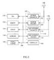
- FIG. 2is a functional block diagram illustrative of one of the wireless communication devices illustrated in FIG. 1 (e.g., the wireless communication device 120 ).
- the wireless communication device 120includes a central processing unit (CPU) 150 .
- CPUcentral processing unit
- the CPU 150may be implemented as a conventional microprocessor, application specific integrated circuit (ASIC), digital signal processor (DSP), programmable gate array (PGA), or the like.
- ASICapplication specific integrated circuit
- DSPdigital signal processor
- PGAprogrammable gate array
- the wireless communication device 120is not limited by the specific form of the CPU 150 .
- the wireless communication device 120 in FIG. 2also contains a memory 152 .
- the memory 152may store instructions and data to control operation of the CPU 150 .
- the memory 152may include random access memory, ready-only memory, programmable memory, flash memory, and the like.
- the wireless communication device 120is not limited by any specific form of hardware used to implement the memory 152 .
- the memory 152may also be integrally formed in whole or in part with the CPU 150 .
- the wireless communication device 120 of FIG. 2also includes conventional components, such as a display 154 and keypad or keyboard 156 . These are conventional components that operate in a known manner and need not be described in greater detail. Other conventional components found in wireless communication devices, such as a USB interface, Bluetooth interface, camera/video device, infrared device, and the like, may also be included in the wireless communication device 120 . For the sake of clarity, these conventional elements are not illustrated in the functional block diagram of FIG. 2 .
- the wireless communication device 120 of FIG. 2also includes a network transmitter 162 such as may be used by the wireless communication device 120 for normal network wireless communication with the base station 104 (see FIG. 1 ).
- FIG. 2also illustrates a network receiver 164 that operates in conjunction with the network transmitter 162 to communicate with the base station 104 .
- the network transmitter 162 and network receiver 164are implemented as a network transceiver 166 .
- the network transceiver 166is connected to an antenna 168 . Operation of the network transceiver 166 and the antenna 168 for communication with the wireless network 102 is well-known in the art and need not be described in greater detail herein.
- the wireless communication device 120 of FIG. 2also includes a non-network transmitter 172 that is used by the wireless communication device 120 for direct communication with other jump-enabled wireless communication devices (e.g., the wireless communication device 122 of FIG. 1 ).
- FIG. 2also illustrates a non-network receiver 174 that operates in conjunction with the non-network transmitter 172 to communicate directly with other jump-enabled wireless (e.g., the wireless communication device 122 of FIG. 1 ).
- the non-network transmitter 172 and non-network receiver 174are implemented as a non-network transceiver 176 .
- the non-network transceiver 176is connected to an antenna 178 .
- the antennas 168 and 178may have common components are implemented as a single antenna.
- the non-network transceiver 176may be designed for operation in accordance with IEEE standard 802.11.
- a jump-enabled wireless communication deviceoperates in an “ad hoc” mode defined by IEEE 802.11, which allows devices to operate in an independent basic service set (IBSS) network configuration.
- IBSSindependent basic service set
- jump-enabled wireless communication devicese.g., the wireless communication devices 120 - 128
- IBSSindependent basic service set
- Low power operationlimits the range of communication to approximately 100 feet.
- the operational range of jump-enabled devicescan be more or less than 100 feet, jump-enabled wireless communication devices are designed for short range communication capability.
- All jump-enabled wireless communication devicesuse the same service set identifier (SSID) and the same physical radio channel (PHY) to permit each jump-enabled wireless communication devices to detect and identify other jump-enabled wireless communication devices.
- SSIDservice set identifier
- PHYphysical radio channel
- all jump-enabled wireless communication devicestake on the responsibilities of the medium access layer (MAC) that controls, manages, and maintains the communication between the jump-enabled wireless communication devices by coordinating access to the shared radio channel and the protocols that operate over the wireless medium.
- the MACis implemented in accordance with IEEE 802.2.
- the transceivermay operate in a direct frequency spread spectrum (DSSS) or a frequency hopping spread spectrum (FHSS) operational mode.
- DSSSdirect frequency spread spectrum
- FHSSfrequency hopping spread spectrum
- the PHY layermay be implemented using infrared transceivers.
- the IEEE 802.11 standarddefines a common operation whether devices are using the ad hoc or the infrastructure mode. The use of the ad hoc mode only affects protocols, so there is no impact on the PHY layer.
- the wireless communication device 120may operate under IEEE 802.11a at 5 gigahertz (GHz) or under IEEE 802.11b/g at 2.4 GHz.
- the first active jump-enabled device(e.g., the wireless communication device 120 ) establishes an IBBS and starts sending beacon signals at approximately 10 per second.
- the beacon signalsare used to maintain synchronization among the various jump-enabled devices.
- Other ad hoc jump-enabled wireless communication devicese.g., the wireless communication device 122 of FIG. 1
- each stationupdates their local internal clock with the time stamp found in the beacon frame. This ensures that all stations are able to perform operations, such as beacon transmission and power management functions, at the same time. Operation of devices under IEEE 802.11 are generally known in the art, and need not be described in greater detail herein.
- a controller 182transmits a portion of data stored in a profile storage 184 to any jump-enabled device with which it can establish a non-network wireless communication link.
- the controller 182may receive portions of data from the corresponding profile storage 184 in the wireless communication device with which the non-network communication link has been established. Details of the profile analysis are provided below.
- controller 182may be implemented as a series of computer instructions stored in the memory 152 and executed by the CPU 150 . However, the controller 182 is shown as a separate block in the functional block diagram of FIG. 2 because it performs a separate function.
- the profile storage 184may be implemented as any convenient data structure, whether in the form of a data table, database, spreadsheet, or the like.
- the profile storage 184may be implemented as part of the memory 152 , but is shown in the functional block diagram of FIG. 2 because it performs a separate function in the wireless communication device 120 .
- the profile storage 184may be implemented on a removable memory card to make it easily transferable to another jump-enabled wireless communication device.
- Some conventional wireless communication devicesutilize a removable Subscriber Identity Module (SIM) card that is easily installed and removed thus making it easy for the consumer to switch phones.
- SIMSubscriber Identity Module
- the profile storage 184could be implemented as part of a SIM card or similar device.
- the various components illustrated in FIG. 2are coupled together by a bus system 186 .
- the bus systemmay include an address bus, data bus, power bus, control bus, and the like.
- the various busses in FIG. 2are illustrated as the bus system 186 .
- system 100functions as a wireless social network implemented on direct communication links between jump-enabled wireless communication devices. Conventional social networks are user-initiated.
- the system 100is auto-initiated in that an initial contact is made automatically based on the determination of matching parameters from the profile storage 184 .
- FIG. 3illustrates a form of personal data and preference data that may be stored in the profile storage 184 .
- the user of a wireless communication device 120may enter personal data.
- the personal data used to described the individual owner of the wireless communication deviceis referred to as a “Jump In” data portion 190 of the profile storage 184 or simply referred to as Jump In data.
- the Jump In datacan include any personal data regarding the user that the user wishes to make available to another jump-enabled wireless communication device.
- Jump In datamay include, but is not limited to, Name, Sex, Age, Height, Weight, Status (e.g., relationship status), Work/Affiliation, Hobbies/Interests, e-mail address, Jump web page link, Phone Number, and the like.
- a Work/Affiliationmay include job information for a professional as well as affiliation, such as a student at a particular school.
- affiliationmay include, by way of example, religious affiliation or sports fan affiliation, such as a fan of a particular football or baseball team.
- Some information, such as an e-mail address and phone numbermay be optional.
- Jump Out datamay include, but is not limited to, Sex, Age, Height, Weight, Status, Work/Affiliation, Hobbies/Interests, and the like. Alternatively, a user may specify no preference at all.
- each of the wireless communication devices for which non-network wireless communication links have been establishedmay exchange the Jump In data with other detected jump-enabled wireless communication devices. For example, when the wireless communication device 126 in FIG. 1 detects the presence of another jump-enabled wireless communication device (i.e., the wireless communication device 128 ), the non-network wireless communication link 138 is established. Once the non-network wireless communication link 138 is established, the wireless communication device 126 transmits its Jump In data to the wireless communication device 128 . At substantially the same time, the wireless communication device 128 transmits its Jump In data to the wireless communication device 126 .
- the wireless communication device 128transmits its Jump In data to the wireless communication device 126 .
- the controllers 182 in each of the respective wireless communication devicescompares the received Jump In data with the Jump Out preference data stored in the respective profile storages 184 . If the received Jump In data provides a suitable match to the Jump Out preference data for each of the wireless communication devices, the controllers 182 in the respective wireless communication devices generates a contact notification to the user of the wireless communication device.
- the wireless communication devices(e.g., the wireless communications devices 126 - 128 of FIG. 1 ) will only exchange Jump In data for data elements for which a Jump Out preference has been stated. For example, if the Jump Out preference data of one wireless communication device indicates no preference for age, height, or weight, the controller 182 may transmit the Jump In data minus the age, height, and weight. Those skilled in the art will appreciate that additional communications must be exchanged between the respective controllers 182 to initially establish which portions of Jump In data must be transmitted.
- the contact notificationmay be in the form of data sent to the display 154 of each respective wireless communication device.
- the wireless communication devicemay provide an audio notification in the form of a beep or other tone.
- the controller 182may cause the wireless communication device to vibrate as a form of notification if the user has placed the wireless communication device in a silent mode.
- the contact notificationis generated only in the event that the controllers 182 in each of the respective wireless communication devices 126 - 128 find a suitable match between the received Jump In personal data and the Jump Out preference data.
- the Jump In data transmitted from the wireless communication device 126 to the wireless communication device 128may provide a suitable match to the Jump Out preference data stored in the profile storage 184 in the wireless communication device 128 . This would provide a suitable match.
- the Jump In personal data transmitted from the wireless communication device 128 to the wireless communication device 126did not provide a suitable match to the jump out preference data in the profile storage 184 in the wireless communication device 126 , neither wireless communication device would provide a contact notification to the user.
- a secondary communicationmust occur between the wireless communication devices to indicate that each of the respective controllers 182 have determined that a match exists and that the contact notifications may be generated in each of the wireless devices.
- the controller 182 and the wireless communication device 126may provide a provisional contact notification to the user of the wireless communication device indicating that some match may have occurred, but indicating that not all preference data matched the received Jump In data.
- the received Jump In datamay match the Jump Out preference data in some categories, but does not match in the Work/Affiliation category.
- the controller 182 in the wireless communication device 126may indicate the area of mismatch and allow the user the option of overriding the preference mismatch. In this event, contact notifications could be sent to the users of both wireless communication devices 126 and 128 .
- a contact notificationmay be provided to the users of both wireless communication devices (e.g., the wireless communication devices 126 - 128 of FIG. 1 ) even if there was a mismatch between the Jump In data and the Jump Out preference data in one or both of the wireless communication devices. This may provide the user of the wireless communication device the options of permitting the contact to proceed.
- wireless communication devicesmay have programmable buttons near the display 154 .
- the display 154may be touch display that permits programmable buttons to be shown on the touch screen itself. The user may activate one of the programmable buttons to continue the contact or to terminate the contact.
- a usermay specify no preference at all in the Jump Out preference data.
- the wireless communication devicecan, in one embodiment, notify the user of any contact with another jump-enabled wireless communication device.
- a user that specifies no Jump Out preference datamay only receive a contact notification if that user's Jump In data matches the Jump Out data of the jump-enabled wireless communication device with which a non-network communication link has been established.
- the users of both wireless communication devicesmay have no preference specified in the Jump Out preference data.
- the controller 182 in each wireless communication devicemay generate a contact notification as soon as the non-network wireless communication link has been established.
- Jump In data and Jump Out datamay be implemented in a flexible manner.
- the usermay prioritize or weight preference data in the Jump Out data such that some factors are more important than others.
- the weighting factorsmay be easily altered by the user.
- the usermay be attending an out-of-town sporting event.
- the usermay alter the weighting factor for affiliation to identify only those nearby jump-enabled wireless communication devices that have the same sports affiliation (i.e., they are fans of the same team).
- a usermay be attending a college homecoming football game and may wish to increase the weighting factor to identify college classmates either by graduate date, major, or a combination thereof.
- the wireless communication devicee.g., the wireless communication device 120
- the wireless communication device 120functions as an auto-detecting social networking device that identifies nearby individuals whose characteristics match the preferences indicated by the user of the wireless communication device.
- the wireless communication device 122is within range of the wireless communication devices 120 and 124 .
- the non-network wireless communication links 134 and 136are established.
- each of the deviceswill transmit the Jump In data to the other detected jump-enabled wireless communication devices.
- the wireless communication device 122transmits its Jump In data to both the wireless communication device 120 and the wireless communication device 124 .
- the wireless communication device 122receives the Jump In data from the wireless communication device 120 and also receives the Jump In data from the wireless communication device 124 .
- the controller 182 in the wireless communication device 122performs an analysis on each of the received Jump In data sets for comparison with the Jump Out preference data stored in the profile storage 184 of the wireless communication device 122 .
- the controller 182may send multiple contact notices to the user if there are satisfactory matches between the multiple sets of Jump In data and the stored Jump Out preference data.
- this conceptmay be extended even further to a large number of jump-enabled wireless communication devices.
- the usermay enter Jump In and Jump Out data into the profile storage 184 in a variety of different manners.
- a relatively simple application program running on the wireless communication devicemay allow the user to enter data via the keyboard 156 .
- the applicationmay also permit the user to arrange the order of preference in the Jump Out data or to declare that certain data elements (e.g., height and weight) have no preference.
- the usermay enter Jump In data and Jump Out preference data remotely.
- a usermay operate the user computer device 112 to enter Jump In and/or Jump Out data via the user computing device 112 and the network 110 .
- the user-entered datais transmitted via the gateway 108 and, ultimately, via the base station 104 to the jump-enabled wireless communication device.
- data for the profile storage 184is provided via a network communication link and downloaded via the wireless communication network 102 to the jump-enabled wireless communication device.
- the non-network wireless communication linksare not intended to supplant communication via the wireless communication network 102 .
- the non-wireless communication linkmay be transitory in nature because of the short communication range.
- the jump-enabled wireless communication deviceis intended to identify nearby contacts with which a person may share common interests.
- the jump-enabled communication deviceserves as a transitory detection and introduction technology, but does not replace normal voice communication, text messaging, photo sharing, video sharing, and the like, which occur through the wireless communication network 102 .
- subsequent communicationmay take place face-to-face or through communication on the wireless communication network, such as email, text messaging, wireless telephone call, or the like.
- the jump-enabled wireless communication device 120also has numerous web-enabled applications. For example, an individual user may set up a jump website with information regarding that individual. In this aspect, the jump website may be similar to individual websites and any other conventional social network. The jump website may be accessed via the network 110 from the user computing device 112 (see FIG. 1 ). Alternatively, the jump website may be accessed by any web-enabled wireless communication device. For example, in FIG. 1 , a non-network wireless communication link 134 has been established between the wireless communication devices 120 and 122 . The wireless devices exchange the Jump In data, as described above, which is analyzed by the controller 182 (see FIG. 2 ).
- the contact indicatorsare generated, as described above.
- the user of a wireless devicee.g., the wireless device 120
- the wireless communication device 120may use the web-browsing capability of the wireless communication device to access an individual jump web page for the individual with whom contact has just been made.
- FIG. 4illustrates in FIG. 4 where the wireless communication device 120 communicates with the base station 104 via the network wireless communication link 130 .
- the wireless communication device 120may use conventional web-browsing techniques to request access to a jump network website 196 via the network 110 . Further, the wireless communication device 120 may request access to an individual jump web page 198 corresponding to the user of the wireless communication device 122 .
- initial data exchange between the wireless communication devices 120 - 122 via the non-network wireless communication link 134may include a link to the individual jump web page 198 . That is, if a match is determined by the controllers 182 in the respective wireless communication devices 120 and 122 , the wireless communication device 120 may use the transmitted jump web page link to easily access the individual jump web page 198 .
- the initial social contact made via the non-network wireless communication link 134can readily provide additional information, in the form of a web link to allow the users of the wireless communication devices to gain further information via the wireless communication network 102 .
- FIG. 4illustrates a communication link 200 between the base station 104 and the network 110 .
- This communication link 200is part of the wireless communication network 102 and includes a number of elements, such as the VSC 106 and Gateway 108 illustrated in FIG. 1 .
- the various network elements connecting the base station 104 with the network 110are replaced merely by the communication link 200 in FIG. 4 .
- the system 100can utilize information from existing social networks.
- each individualhas a list of “friends” or “contacts” that are maintained for that individual.
- a jump-enabled wireless communication devicee.g., the wireless communication device 120
- a social network website 200includes an individual web page 202 .
- a contact list 204contains a list of all individuals that the owner of the individual web page 202 has identified as part of that individual's social network.
- the contact list 204may be downloaded via the wireless communication network 102 to the wireless communication device 120 for storage in the profile storage 184 .
- the wireless communication device 120searches for contacts in the manner described above.
- a non-network wireless communication linke.g., the non-network wireless communication link 134
- the Jump In datais exchanged between the wireless communication devices 120 and 122 , in the manner described above.
- the wireless communication device 120may immediately generate a contact notification to the user of the wireless communication device 120 .
- the controller 184need not do a detailed comparison between the Jump In data received from the wireless communication device 122 and the store Jump Out preference data stored in the profile storage 184 .
- the wireless communication device 120may transmit a web link to the individual web page 202 to enable the user of the wireless communication device 122 to gain additional information about the individual user of the wireless communication device 120 . This may be in place of, or in addition to, an individual jump web page link, described above.
- system 100allows seamless integration with existing social network websites as well as a jump network website.
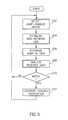
- the operation of the system 100is illustrated in the flow chart of FIG. 5 where a jump-enabled wireless communication device detects the proximity of another jump-enabled wireless communication device in step 202 .
- a technique for peer-to-peer communicationhas already been described with respect to IEEE 802.11. Other peer-to-peer technologies may also be satisfactory to implement the non-network wireless communication links.
- the system 100is not limited by the specific form of technology used to implement the non-network wireless communication links.
- the wireless communication devicee.g., the wireless communication device 120
- the wireless communication device 120establishes a non-network wireless communication link with another jump-enabled wireless communication device.
- the two jump-enabled wireless communication devicesexchange the Jump In data portions of the respective profile storage 184 in step 206 .
- Thismay include, for example, the total exchange of all data stored in the Jump In data 190 or may include the transmission only of portions of the Jump In data 190 that correspond to portions of the Jump Out data for which a user has specified a preference.
- step 208the controller of each wireless communication device analyzes the received Jump In data with respect to the Jump Out preference data 192 stored in the profile storage 184 .
- a variety of different analysis techniqueshave been discussed above, including, for example, importance of various factors, the weighting of different factors, and the like.
- the usermay specify the importance of various factors merely by the sequence in which the preferences are arranged.
- the usermay assign various importance levels to various factors. For example, the most important factors may be identified by a numeral “1” while a second tier of importance may be identified by a numeral “2.”
- Various other matching algorithmsmay be used.
- the system 100is not limited by the specific preference factors, or by the manner in which the preference factors are analyzed.
- a matchoccurs in decision 210 and, in step 212 , the wireless communication device generates a contact notification.
- the contact notificationcan occur based on individual analysis, or may be restricted to a situation in which both wireless communication devices have determined that a match exists. Various other techniques for determining whether a contact notification should be generated have been described above. If the controller determines that a match has not occurred, the result of decision 210 is NO. In that event, or following the generation of the contact notification in step 212 , the system returns to step 202 to detect additional jump-enabled wireless communication devices.
- any two components herein combined to achieve a particular functionalitycan be seen as “associated with” each other such that the desired functionality is achieved, irrespective of architectures or intermedial components.
- any two components so associatedcan also be viewed as being “operably connected”, or “operably coupled”, to each other to achieve the desired functionality.
Landscapes
- Engineering & Computer Science (AREA)
- Computer Networks & Wireless Communication (AREA)
- Signal Processing (AREA)
- Mobile Radio Communication Systems (AREA)
Abstract
Description
Claims (19)
Priority Applications (49)
| Application Number | Priority Date | Filing Date | Title |
|---|---|---|---|
| US12/397,225US7970351B2 (en) | 2009-03-03 | 2009-03-03 | System and method for direct communication between wireless communication devices |
| US12/616,958US8190119B2 (en) | 2009-03-03 | 2009-11-12 | System and method for direct communication between wireless communication devices |
| BRPI1009289ABRPI1009289A2 (en) | 2009-03-03 | 2010-03-02 | system and method for direct communication between wireless communication devices |
| JP2011553049AJP2012520014A (en) | 2009-03-03 | 2010-03-02 | System and method for direct communication between wireless communication devices |
| KR1020117023173AKR20110138361A (en) | 2009-03-03 | 2010-03-02 | System and method for direct communication between wireless communication devices |
| EP10749219AEP2404478A4 (en) | 2009-03-03 | 2010-03-02 | System and method for direct communication between wireless communication devices |
| EP12158188AEP2472459A3 (en) | 2009-03-03 | 2010-03-02 | System and method for direct communication between wireless communication devices |
| PCT/US2010/025949WO2010101940A2 (en) | 2009-03-03 | 2010-03-02 | System and method for direct communication between wireless communication devices |
| CN201080019684XACN102428748A (en) | 2009-03-03 | 2010-03-02 | System and method for direct communication between wireless communication devices |
| EP12158191AEP2472460A3 (en) | 2009-03-03 | 2010-03-02 | System and method for direct communication between wireless communication devices |
| SG2011062742ASG173903A1 (en) | 2009-03-03 | 2010-03-02 | System and method for direct communication between wireless communication devices |
| US12/958,296US9077564B2 (en) | 2009-03-03 | 2010-12-01 | System and method for dynamic formation of a communication network using wireless communication devices |
| US13/093,998US8995923B2 (en) | 2009-03-03 | 2011-04-26 | System and method for management of a dynamic network using wireless communication devices |
| US13/158,151US8774753B2 (en) | 2009-03-03 | 2011-06-10 | System and method for direct communication between wireless communication devices |
| US13/163,416US8295803B2 (en) | 2009-03-03 | 2011-06-17 | System and method for direct communication between wireless communication devices |
| US13/363,943US9179296B2 (en) | 2009-03-03 | 2012-02-01 | System and method for device authentication in a dynamic network using wireless communication devices |
| US13/363,696US9586139B2 (en) | 2009-03-03 | 2012-02-01 | System and method for game play in a dynamic communication network |
| US13/398,727US9064374B2 (en) | 2009-03-03 | 2012-02-16 | System and method for gaming in a dynamic network using wireless communication devices |
| US13/452,015US9715833B2 (en) | 2009-03-03 | 2012-04-20 | System and method for wireless communication in an educational setting |
| US13/604,501US10244393B2 (en) | 2009-03-03 | 2012-09-05 | System and method for gaming using wireless communication devices |
| US13/604,418US9055439B2 (en) | 2009-03-03 | 2012-09-05 | System and method for handset operation in a wireless communication network |
| US13/720,695US10410251B2 (en) | 2009-03-03 | 2012-12-19 | System and method for handset operation in a wireless communication network |
| US13/769,053US20130231088A1 (en) | 2009-03-03 | 2013-02-15 | System and method for social profiling using wireless communication devices |
| US13/838,272US10387918B2 (en) | 2009-03-03 | 2013-03-15 | System and method for retail sales using wireless communication devices in a wireless communication network |
| US13/834,001US9510148B2 (en) | 2009-03-03 | 2013-03-15 | System and method for wireless communication to permit audience participation |
| US13/834,359US9271054B2 (en) | 2009-03-03 | 2013-03-15 | System and method for WiFi video streaming |
| US13/925,328US9986268B2 (en) | 2009-03-03 | 2013-06-24 | System and method for multi-channel WiFi video streaming |
| US13/944,670US10616619B2 (en) | 2009-03-03 | 2013-07-17 | System and method for multi-channel WiFi video streaming |
| US14/274,192US9245408B2 (en) | 2009-03-03 | 2014-05-09 | System and method for gaming using wireless communication devices |
| US14/455,559US20140344847A1 (en) | 2009-03-03 | 2014-08-08 | System and method for multi-channel video streaming |
| US14/531,118US9609513B2 (en) | 2009-03-03 | 2014-11-03 | System and method for device authentication in a dynamic network using wireless communication devices |
| US14/577,822US10009638B2 (en) | 2009-03-03 | 2014-12-19 | System and method for multi-channel WiFi video streaming |
| US14/706,869US9439071B2 (en) | 2009-03-03 | 2015-05-07 | Billing engine and method of use |
| US14/706,894US9485656B2 (en) | 2009-03-03 | 2015-05-07 | System and method for handset operation in a wireless communication network |
| US14/743,921US9675883B2 (en) | 2009-03-03 | 2015-06-18 | System and method for wireless communication to permit audience participation |
| US14/862,781US20160014455A1 (en) | 2009-03-03 | 2015-09-23 | System and method for video streaming in a dynamic network using wireless communication devices |
| US15/050,335US10142661B2 (en) | 2009-03-03 | 2016-02-22 | Mobile communication device and method of operation |
| US15/050,347US10051293B2 (en) | 2009-03-03 | 2016-02-22 | System and method for operation of a temporary control facility for video distribution in a venue |
| US15/050,352US10154290B2 (en) | 2009-03-03 | 2016-02-22 | System and method for wireless distribution of television channels in a venue |
| US15/050,332US10129568B2 (en) | 2009-03-03 | 2016-02-22 | System and method for transmission of multiple video streams to mobile communication devices |
| US15/246,165US9787855B2 (en) | 2009-03-03 | 2016-08-24 | Billing engine and method of use |
| US15/278,484US10387946B2 (en) | 2009-03-03 | 2016-09-28 | System and method for wireless communication to permit audience participation |
| US15/339,600US9749861B2 (en) | 2009-03-03 | 2016-10-31 | System and method for handset operation in a wireless communication network |
| US15/444,140US9662571B1 (en) | 2009-03-03 | 2017-02-27 | System and method for game play in a dynamic communication network |
| US15/593,116US11176596B2 (en) | 2009-03-03 | 2017-05-11 | System and method for wireless communication to permit audience participation |
| US15/604,461US9855500B2 (en) | 2009-03-03 | 2017-05-24 | System and method for game play in a dynamic communication network |
| US15/728,287US10264140B2 (en) | 2009-03-03 | 2017-10-09 | Billing engine and method of use |
| US15/948,913US10863234B2 (en) | 2009-03-03 | 2018-04-09 | System and method for secure appliance operation |
| US16/268,255US10637997B2 (en) | 2009-03-03 | 2019-02-05 | Billing engine and method of use |
Applications Claiming Priority (1)
| Application Number | Priority Date | Filing Date | Title |
|---|---|---|---|
| US12/397,225US7970351B2 (en) | 2009-03-03 | 2009-03-03 | System and method for direct communication between wireless communication devices |
Related Child Applications (1)
| Application Number | Title | Priority Date | Filing Date |
|---|---|---|---|
| US12/616,958Continuation-In-PartUS8190119B2 (en) | 2009-03-03 | 2009-11-12 | System and method for direct communication between wireless communication devices |
Publications (2)
| Publication Number | Publication Date |
|---|---|
| US20100227554A1 US20100227554A1 (en) | 2010-09-09 |
| US7970351B2true US7970351B2 (en) | 2011-06-28 |
Family
ID=42678683
Family Applications (1)
| Application Number | Title | Priority Date | Filing Date |
|---|---|---|---|
| US12/397,225Active2030-03-19US7970351B2 (en) | 2009-03-03 | 2009-03-03 | System and method for direct communication between wireless communication devices |
Country Status (1)
| Country | Link |
|---|---|
| US (1) | US7970351B2 (en) |
Cited By (17)
| Publication number | Priority date | Publication date | Assignee | Title |
|---|---|---|---|---|
| US20120284412A1 (en)* | 2011-05-05 | 2012-11-08 | Saidi Armine | Networking device, system and method for the creation of portable proximity communication networks |
| EP2706763A1 (en) | 2012-09-05 | 2014-03-12 | E3 Llc | Direct wireless communication at a venue |
| US20140213227A1 (en)* | 2013-01-28 | 2014-07-31 | Bindu Rama Rao | Mobile device capable of substantially synchronized sharing of streaming media, calls and other content with other devices |
| US20150156702A1 (en)* | 2012-08-03 | 2015-06-04 | Intel Corporation | Communication path switching for mobile devices |
| US9306686B2 (en) | 2014-05-02 | 2016-04-05 | Macmillan New Ventures, LLC | Audience response communication system |
| US9439071B2 (en) | 2009-03-03 | 2016-09-06 | Mobilitie, Llc | Billing engine and method of use |
| US9485656B2 (en) | 2009-03-03 | 2016-11-01 | Mobilitie, Llc | System and method for handset operation in a wireless communication network |
| US9510148B2 (en) | 2009-03-03 | 2016-11-29 | Mobilitie, Llc | System and method for wireless communication to permit audience participation |
| US9609513B2 (en) | 2009-03-03 | 2017-03-28 | Mobilitie, Llc | System and method for device authentication in a dynamic network using wireless communication devices |
| US9662571B1 (en) | 2009-03-03 | 2017-05-30 | Mobilitie, Llc | System and method for game play in a dynamic communication network |
| EP3185601A1 (en) | 2012-02-01 | 2017-06-28 | Mobilitie, LLC | System and method for device authentication in a dynamic network using wireless communication devices and transfer from mobile to wifi network |
| US9715833B2 (en) | 2009-03-03 | 2017-07-25 | Mobilitie, LLP | System and method for wireless communication in an educational setting |
| US9986268B2 (en) | 2009-03-03 | 2018-05-29 | Mobilitie, Llc | System and method for multi-channel WiFi video streaming |
| US10051293B2 (en) | 2009-03-03 | 2018-08-14 | Mobilitie, Llc | System and method for operation of a temporary control facility for video distribution in a venue |
| CN108540978A (en)* | 2017-03-06 | 2018-09-14 | 波音公司 | Secure multi-payload antenna operator operation |
| US10616619B2 (en) | 2009-03-03 | 2020-04-07 | Mobilitie, Llc | System and method for multi-channel WiFi video streaming |
| US11038871B2 (en)* | 2018-06-27 | 2021-06-15 | Motorola Solutions, Inc. | Two-step authentication using push to talk |
Families Citing this family (13)
| Publication number | Priority date | Publication date | Assignee | Title |
|---|---|---|---|---|
| US20100250135A1 (en)* | 2009-03-26 | 2010-09-30 | Motorola, Inc. | Method and Device for Determining Proximity of a Social Network Service Acquaintance |
| US8924570B2 (en)* | 2010-11-23 | 2014-12-30 | International Business Machines Corporation | Temporary collaborative ad-hoc network of hardware nodes to perform function |
| US9679336B2 (en)* | 2011-10-19 | 2017-06-13 | Facebook, Inc. | Social ad hoc networking protocol and presentation layer |
| US9037653B2 (en) | 2011-12-09 | 2015-05-19 | Facebook, Inc. | Mobile ad hoc networking |
| US20130254277A1 (en)* | 2012-03-21 | 2013-09-26 | Alcatel-Lucent Usa Inc. | Methods And Networks For Device To Device Communication |
| US8902907B2 (en)* | 2012-10-05 | 2014-12-02 | Futurewei Technologies, Inc. | Terminal based grouping virtual transmission and reception in wireless networks |
| US8812026B2 (en) | 2012-11-13 | 2014-08-19 | Intel Corporation | System and method for autonomous connectivity to improve location-based information |
| KR102069876B1 (en)* | 2012-12-21 | 2020-01-23 | 삼성전자주식회사 | Electronic device, Personal cloud apparatus, Personal cloud system and Method for registering personal cloud apparatus in user portal server thereof |
| WO2014152677A2 (en)* | 2013-03-15 | 2014-09-25 | Mobilitie, Llc | System and method for multi-channel wifi video streaming |
| JP5755275B2 (en)* | 2013-03-22 | 2015-07-29 | ヤフー株式会社 | Affiliate system, affiliate method and server |
| CN114205925B (en)* | 2015-09-29 | 2024-03-19 | 株式会社宙连 | Control devices and storage media |
| KR102032421B1 (en)* | 2017-05-12 | 2019-10-15 | 주식회사 팬라이트 | Crowd control system for controlling plurality of user devices |
| CN115038089B (en)* | 2022-08-09 | 2022-11-08 | 广州博今网络技术有限公司 | Multi-terminal data monitoring and collecting method based on information extraction |
Citations (6)
| Publication number | Priority date | Publication date | Assignee | Title |
|---|---|---|---|---|
| EP1434459A2 (en) | 1999-08-24 | 2004-06-30 | Nokia Corporation | Mobile Communications Subscriber Profile Matching System |
| US7249182B1 (en) | 2002-02-27 | 2007-07-24 | Nokia Corporation | Personal profile sharing and management for short-range wireless terminals |
| US7254406B2 (en) | 2002-06-10 | 2007-08-07 | Suman Beros | Method and apparatus for effecting a detection of mobile devices that are proximate and exhibit commonalities between specific data sets, or profiles, associated with the persons transporting the mobile devices |
| US20080215689A1 (en) | 2006-12-29 | 2008-09-04 | Ilmo Pietila | Contact device and a network of contact devices |
| US20100227610A1 (en)* | 2009-03-03 | 2010-09-09 | Mobilitie LLC | System and method for direct communication between wireless communication devices |
| US20110076948A1 (en)* | 2009-03-03 | 2011-03-31 | E3 Llc | System and method for dynamic formation of a communication network using wireless communication devices |
- 2009
- 2009-03-03USUS12/397,225patent/US7970351B2/enactiveActive
Patent Citations (6)
| Publication number | Priority date | Publication date | Assignee | Title |
|---|---|---|---|---|
| EP1434459A2 (en) | 1999-08-24 | 2004-06-30 | Nokia Corporation | Mobile Communications Subscriber Profile Matching System |
| US7249182B1 (en) | 2002-02-27 | 2007-07-24 | Nokia Corporation | Personal profile sharing and management for short-range wireless terminals |
| US7254406B2 (en) | 2002-06-10 | 2007-08-07 | Suman Beros | Method and apparatus for effecting a detection of mobile devices that are proximate and exhibit commonalities between specific data sets, or profiles, associated with the persons transporting the mobile devices |
| US20080215689A1 (en) | 2006-12-29 | 2008-09-04 | Ilmo Pietila | Contact device and a network of contact devices |
| US20100227610A1 (en)* | 2009-03-03 | 2010-09-09 | Mobilitie LLC | System and method for direct communication between wireless communication devices |
| US20110076948A1 (en)* | 2009-03-03 | 2011-03-31 | E3 Llc | System and method for dynamic formation of a communication network using wireless communication devices |
Non-Patent Citations (1)
| Title |
|---|
| Nintendo-DS Lite Instruction Booklet; 2007; Cover and pp. 1-2, 14-15, and 16-17; US and Canada. |
Cited By (31)
| Publication number | Priority date | Publication date | Assignee | Title |
|---|---|---|---|---|
| US9715833B2 (en) | 2009-03-03 | 2017-07-25 | Mobilitie, LLP | System and method for wireless communication in an educational setting |
| US9787855B2 (en) | 2009-03-03 | 2017-10-10 | Mobilitie, Llc | Billing engine and method of use |
| US11176596B2 (en) | 2009-03-03 | 2021-11-16 | Mobilitie, Llc | System and method for wireless communication to permit audience participation |
| US10616619B2 (en) | 2009-03-03 | 2020-04-07 | Mobilitie, Llc | System and method for multi-channel WiFi video streaming |
| US10387946B2 (en) | 2009-03-03 | 2019-08-20 | Mobilitie, Llc | System and method for wireless communication to permit audience participation |
| US10264140B2 (en) | 2009-03-03 | 2019-04-16 | Mobilitie, Llc | Billing engine and method of use |
| US10154290B2 (en) | 2009-03-03 | 2018-12-11 | Mobilitie, Llc | System and method for wireless distribution of television channels in a venue |
| US9439071B2 (en) | 2009-03-03 | 2016-09-06 | Mobilitie, Llc | Billing engine and method of use |
| US9485656B2 (en) | 2009-03-03 | 2016-11-01 | Mobilitie, Llc | System and method for handset operation in a wireless communication network |
| US9510148B2 (en) | 2009-03-03 | 2016-11-29 | Mobilitie, Llc | System and method for wireless communication to permit audience participation |
| US9609513B2 (en) | 2009-03-03 | 2017-03-28 | Mobilitie, Llc | System and method for device authentication in a dynamic network using wireless communication devices |
| US9662571B1 (en) | 2009-03-03 | 2017-05-30 | Mobilitie, Llc | System and method for game play in a dynamic communication network |
| US9675883B2 (en) | 2009-03-03 | 2017-06-13 | Mobilitie, Llc | System and method for wireless communication to permit audience participation |
| US10142661B2 (en) | 2009-03-03 | 2018-11-27 | Mobilitie, Llc | Mobile communication device and method of operation |
| US10129568B2 (en) | 2009-03-03 | 2018-11-13 | Mobilitie, Llc | System and method for transmission of multiple video streams to mobile communication devices |
| US10051293B2 (en) | 2009-03-03 | 2018-08-14 | Mobilitie, Llc | System and method for operation of a temporary control facility for video distribution in a venue |
| US9986268B2 (en) | 2009-03-03 | 2018-05-29 | Mobilitie, Llc | System and method for multi-channel WiFi video streaming |
| US9855500B2 (en) | 2009-03-03 | 2018-01-02 | Mobilitie, Llc | System and method for game play in a dynamic communication network |
| US9749861B2 (en) | 2009-03-03 | 2017-08-29 | Mobilite, LLC | System and method for handset operation in a wireless communication network |
| US10009638B2 (en) | 2009-03-03 | 2018-06-26 | Mobilitie, Llc | System and method for multi-channel WiFi video streaming |
| US20120284412A1 (en)* | 2011-05-05 | 2012-11-08 | Saidi Armine | Networking device, system and method for the creation of portable proximity communication networks |
| US9088439B2 (en)* | 2011-05-05 | 2015-07-21 | Armine SAIDI | Networking device, system and method for the creation of portable proximity communication networks |
| EP3185601A1 (en) | 2012-02-01 | 2017-06-28 | Mobilitie, LLC | System and method for device authentication in a dynamic network using wireless communication devices and transfer from mobile to wifi network |
| US9369912B2 (en)* | 2012-08-03 | 2016-06-14 | Intel Corporation | Communication path switching for mobile devices |
| US20150156702A1 (en)* | 2012-08-03 | 2015-06-04 | Intel Corporation | Communication path switching for mobile devices |
| EP2706763A1 (en) | 2012-09-05 | 2014-03-12 | E3 Llc | Direct wireless communication at a venue |
| US20140213227A1 (en)* | 2013-01-28 | 2014-07-31 | Bindu Rama Rao | Mobile device capable of substantially synchronized sharing of streaming media, calls and other content with other devices |
| US9306686B2 (en) | 2014-05-02 | 2016-04-05 | Macmillan New Ventures, LLC | Audience response communication system |
| CN108540978A (en)* | 2017-03-06 | 2018-09-14 | 波音公司 | Secure multi-payload antenna operator operation |
| CN108540978B (en)* | 2017-03-06 | 2023-07-14 | 波音公司 | Secure multiple payload antenna operator operation |
| US11038871B2 (en)* | 2018-06-27 | 2021-06-15 | Motorola Solutions, Inc. | Two-step authentication using push to talk |
Also Published As
| Publication number | Publication date |
|---|---|
| US20100227554A1 (en) | 2010-09-09 |
Similar Documents
| Publication | Publication Date | Title |
|---|---|---|
| US7970351B2 (en) | System and method for direct communication between wireless communication devices | |
| US8774753B2 (en) | System and method for direct communication between wireless communication devices | |
| CN102907137B (en) | The self-adaptive service quality of Wireless Telecom Equipment | |
| US7720490B2 (en) | Location update operations for idle mode terminals with a plurality of wireless communication interfaces | |
| EP2048898B1 (en) | Inter-radio access technology signal measurement | |
| US8929891B2 (en) | Measurement control for handover from one radio access technology to another | |
| EP2046091B1 (en) | Proximity of user equipment to a home local network | |
| JP5815690B2 (en) | System and method for providing network access to electronic devices | |
| EP1246487A2 (en) | Mode monitoring and identification through distributed radio | |
| US20050181734A1 (en) | Automatic connection of a mobile device to a wireless network | |
| CN106170125A (en) | Urgent call for many SIM device | |
| CN108990038A (en) | Device-to-device (D2D) discovery of operator's auxiliary | |
| JP2008544672A (en) | System, terminal, network entity, method, and computer program product for system selection in a multi-mode communication system | |
| JP2012514903A (en) | Dual base station in wireless communication system | |
| JP2008092474A (en) | Communication terminal device, server, and wireless communication system | |
| US7725115B2 (en) | Paging operation for idle mode terminals with a plurality of wireless interfaces | |
| US20070286135A1 (en) | Method and system for enabling reception of targeted services to a handheld communication device | |
| JP5656925B2 (en) | Network converter | |
| US8447286B2 (en) | Multi-interface user terminal | |
| WO2020248139A1 (en) | Cell selection method and apparatus, communication device and storage medium | |
| US20080014936A1 (en) | Methods and devices for communication network selection by recipient | |
| KR100962380B1 (en) | Method for forming a buddy group using short-range wireless communication and the terminal | |
| CN109451498B (en) | Network authentication method and related product | |
| CN119071862A (en) | A cell residence method and terminal equipment | |
| Atallah et al. | Multi-standard Wireless Front-Ends |
Legal Events
| Date | Code | Title | Description |
|---|---|---|---|
| AS | Assignment | Owner name:MOBILITIE LLC, CALIFORNIA Free format text:ASSIGNMENT OF ASSIGNORS INTEREST;ASSIGNORS:JABARA, GARY B.;KARMIS, CHRISTOS;REEL/FRAME:025475/0201 Effective date:20101210 | |
| AS | Assignment | Owner name:E3 LLC, CALIFORNIA Free format text:ASSIGNMENT OF ASSIGNORS INTEREST;ASSIGNOR:MOBILITIE LLC;REEL/FRAME:025499/0484 Effective date:20101210 | |
| STCF | Information on status: patent grant | Free format text:PATENTED CASE | |
| AS | Assignment | Owner name:MOBILITIE, LLC, CALIFORNIA Free format text:ASSIGNMENT OF ASSIGNORS INTEREST;ASSIGNOR:E3, LLC;REEL/FRAME:031276/0635 Effective date:20130913 | |
| FPAY | Fee payment | Year of fee payment:4 | |
| MAFP | Maintenance fee payment | Free format text:PAYMENT OF MAINTENANCE FEE, 8TH YR, SMALL ENTITY (ORIGINAL EVENT CODE: M2552); ENTITY STATUS OF PATENT OWNER: SMALL ENTITY Year of fee payment:8 | |
| AS | Assignment | Owner name:CIT BANK, N.A., AS ADMINISTRATIVE AGENT, NEW JERSE Free format text:SECURITY INTEREST;ASSIGNOR:MOBILITIE, LLC;REEL/FRAME:050797/0058 Effective date:20191018 Owner name:CIT BANK, N.A., AS ADMINISTRATIVE AGENT, NEW JERSEY Free format text:SECURITY INTEREST;ASSIGNOR:MOBILITIE, LLC;REEL/FRAME:050797/0058 Effective date:20191018 | |
| FEPP | Fee payment procedure | Free format text:ENTITY STATUS SET TO UNDISCOUNTED (ORIGINAL EVENT CODE: BIG.); ENTITY STATUS OF PATENT OWNER: LARGE ENTITY | |
| FEPP | Fee payment procedure | Free format text:ENTITY STATUS SET TO SMALL (ORIGINAL EVENT CODE: SMAL); ENTITY STATUS OF PATENT OWNER: SMALL ENTITY | |
| AS | Assignment | Owner name:MOBILITIE, LLC, CALIFORNIA Free format text:RELEASE BY SECURED PARTY;ASSIGNOR:CIT BANK, N.A., AS ADMINISTRATIVE AGENT;REEL/FRAME:057698/0335 Effective date:20210930 | |
| AS | Assignment | Owner name:IP INVESTEMENT HOLDINGS, LLC, CALIFORNIA Free format text:ASSIGNMENT OF ASSIGNORS INTEREST;ASSIGNOR:MOBILITIE, LLC;REEL/FRAME:057972/0773 Effective date:20210928 | |
| MAFP | Maintenance fee payment | Free format text:PAYMENT OF MAINTENANCE FEE, 12TH YR, SMALL ENTITY (ORIGINAL EVENT CODE: M2553); ENTITY STATUS OF PATENT OWNER: SMALL ENTITY Year of fee payment:12 |