US7970179B2 - Iris data extraction - Google Patents
Iris data extractionDownload PDFInfo
- Publication number
- US7970179B2 US7970179B2US11/526,096US52609606AUS7970179B2US 7970179 B2US7970179 B2US 7970179B2US 52609606 AUS52609606 AUS 52609606AUS 7970179 B2US7970179 B2US 7970179B2
- Authority
- US
- United States
- Prior art keywords
- image
- pupil
- iris
- eye
- determining
- Prior art date
- Legal status (The legal status is an assumption and is not a legal conclusion. Google has not performed a legal analysis and makes no representation as to the accuracy of the status listed.)
- Active, expires
Links
Images


Classifications
- G—PHYSICS
- G06—COMPUTING OR CALCULATING; COUNTING
- G06V—IMAGE OR VIDEO RECOGNITION OR UNDERSTANDING
- G06V40/00—Recognition of biometric, human-related or animal-related patterns in image or video data
- G06V40/10—Human or animal bodies, e.g. vehicle occupants or pedestrians; Body parts, e.g. hands
- G06V40/18—Eye characteristics, e.g. of the iris
- G06V40/193—Preprocessing; Feature extraction
Definitions
- the present inventionrelates to biometric identification using an iris image, and more particularly, to identification of the iris image in an eye image for extracting iris data.
- irisDue to the unique character of each individual's iris, various systems attempt to use the iris for biometric identification. Such systems generally capture an image of the entire eye, which includes an image of the iris. The iris image must be identified before the patterns of the iris, which are unique to each individual, can be extracted for biometric analysis. In other words, the area that corresponds to the iris must be segmented, or separated, from the other components in the entire eye image. Conventional systems generally determine the boundaries of the iris image by searching for the edges that correspond with these boundaries. In particular, these conventional approaches depend on the contrast between the edges and the area around the edges, referred to as edge strength, to identify the boundaries.
- this approachsuffers from many disadvantages and fails to provide a robust method for finding and extracting iris data. For instance, because the edges between the iris and the sclera (limbic boundary) are often weak and hard to detect, conventional systems are beset with the difficult challenge of enhancing the weak edges to identify the iris boundaries adequately.
- U.S. Pat. No. 5,291,560 to Daugmanimplements an integro-differential operator for locating the circular edges of the iris and pupil regions, as well as edges of the arcs of the upper and lower eyelids.
- Daugmanapproximates the edge of the pupil to be a circle and sums the brightness along each circle with trial center coordinates (x 0 , y 0 ) and incrementally increasing radius r.
- trial center coordinates (x 0 , y 0 )can be evaluated to find the center of the pupil.
- center coordinates (x 0 , y 0 )do not coincide with the pupil's center, some portions of the circle will still lie within the pupil region when the brightness suddenly changes. However, if the center coordinates (x 0 , y 0 ) do indeed coincide with the pupil's center, when the brightness suddenly changes, no portions of the circle should be in the pupil region, so the rate-of-change of the brightness, or luminance, should be at its maximum.
- the problem of locating the pupil's boundaryis reduced to an optimization problem where a three-parameter space is searched for the best combination of center coordinates (x 0 , y 0 ) and radius r, i.e., where the absolute value of the partial derivative with respect to radius r of the integrated luminance along the circle is maximum.
- the search of the three-parameter spacecan occur in an iterative process of gradient-ascent.
- Daugman's approach for finding the outer edge of the irisis similar to finding the edge of the pupil but the previous approach is modified to account for the fact that i) the pupil is not always centered in the iris, ii) the upper and lower eyelids obscure top and bottom portions of the iris, and iii) the iris, unlike the pupil, has a concentric texture and may itself contain interior circular edges which could create sudden changes in integrated luminance along a circle.
- the process for detecting the iris edgetherefore is restricted to two 45-degree arcs along the horizontal meridian and an area integral is used rather than a contour integral.
- the luminance for arcs of increasing radius and centered at the pupil centerare evaluated as an area integral in polar coordinates.
- the value of radius r which corresponds to the maximum in the rate-of-change of integrated luminance with respect to radius rcorresponds to an edge of the iris. This calculation is made for each arc separately since the left and right edges of the iris may be at different distances, i.e. radius r, from the pupil's center.
- the algorithmcan fail because it is susceptible to changes in luminance that do not occur at the boundaries, such as those caused by reflections, noise from a poor image, contact lens edges, or even by actual features or textures in the eye.
- the use of integro-differential operatorsare sensitive to the specular spot reflection of non-diffused artificial light that can occur inside the pupil, and such spots can cause the detection of the correct inner boundary to fail. Therefore, Daugman has also proposed the use of Gaussian filtering to smooth the texture patterns inside the iris region to avoid incorrect detection of false limbic boundaries, but this approach involves heavy computational complexity.
- the process abovemust be modified to account for the fact that the edges are not clean edges and are somewhat fuzzy.
- the integrated luminance of a shell summust be used rather than the integrated luminance of the circle, i.e. the rate-of-change of a shell sum is maximized. Therefore, use of the Daugman may require ad hoc adjustments of the shell size parameter.
- U.S. Pat. Nos. 5,751,836 and 5,752,596 to Wildes et al.also implement edge detection algorithms.
- the process disclosed by Wildes et al.initially averages and reduces the input image using a low-pass Gaussian filter that spatially averages and reduces high frequency noise. The result is then subsampled without further loss of information but with the advantage of reducing computational demands.
- the irisis then localized by locating the limbic (outer) boundary of the iris, the pupillary (inner) boundary of the iris, and the eyelid boundaries. The iris is then taken as the portion of the image that is outside the pupillary boundary, inside the limbic boundary, above the lower eyelid, and below the upper eyelid.
- the first step in locating each component of the iris boundaryemploys a gradient-based edge detection operation which forms an edge map by calculating the first derivatives of intensity values and then thresholding the result.
- Wildes et al.bias the derivatives in the horizontal direction for detecting the eyelids, and in the vertical direction for detecting the limbic boundary.
- the application of the process taught by Wildes et al.has the disadvantage of requiring threshold values to be chosen for edge detection. Poor choice of threshold values can eliminate critical edge points possibly causing failure in the detection of the circles and arcs making up the boundaries of the iris.
- the second stepemploys a transform like that generally disclosed in U.S. Pat. No. 3,069,654 to Hough.
- the limbic boundaryis modeled as a circle with center coordinates (x 0 , y 0 ) and radius r.
- the detected edge pixels from the edge mapare thinned to increase the number of meaningful edges.
- the pixelsare then histogrammed into a three-dimensional space formed by circle parameters x 0 , y 0 , and r (Hough circle transform).
- the (x 0 , y 0 , r) point with the most number of votes from the histogramming processthen represents the limbic boundary.
- the pupilis also modeled as a circle and the edge pixels are thinned and histogrammed into (x 0 , y 0 , r) values, where the (x 0 , y 0 , r) point with the most votes are taken to represent the pupillary boundary.
- the eyelid boundariesare modeled as two separate parabolic arcs. The eyelid edges are thinned and histogrammed according to the parameters necessary to define a parabolic arc (parabolic Hough transform), where the set of parameters with the most votes is taken to represent the upper or lower eyelids.
- the Hough circle transformis also used, but unlike Wildes et al., Masek first employs Canny edge detection to create the edge map. Masek modifies Kovesi's Canny edge detection to allow for the weighting of gradients as Wildes et al. teaches for the detection of the limbic boundary with a vertical bias.
- the Hough circle transformis applied to find the limbic boundary first and then the pupillary boundary where the range of radius values for the search is set manually depending on the database used and the typical radius values in the images.
- Masekapplies Canny edge detection where only horizontal gradient information is taken.
- the eyelidsare then located by fitting a line to the upper and lower eyelids through a linear Hough transform.
- a second horizontal lineis formed from the intersection of the fitted line and the limbic boundary closest to the pupil in order to achieve maximum isolation of the eyelids.
- the use of the linear Hough transformis less computationally demanding than the use of the parabolic Hough transforms taught by Wildes et al.
- maximum isolation of the eyelid regionscan isolate substantial portions of the iris itself and make the matching process less accurate.
- Masekrequires threshold values to be specified to create the edge maps, and as with Wildes et al., these threshold values are dependent on the database and the quality of images in the database. Poor choice of threshold values can eliminate critical edge points possibly causing failure in the detection of the circles and arcs making up the boundaries of the iris.
- Lui et al.disclose a process known as ND_IRIS, which attempts to improve Masek's approach toward segmentation.
- Masek's methoddetects the outer iris boundary first and then detects the inner boundary within the outer boundary, but Lui et al. reverses this order by detecting the inner boundary first since there is often greater contrast between the pupil and iris, and thus the inner boundary can be easier to localize.
- Lui at al.also point out that edge pixels that do not lie on the iris boundary often cause the Hough transform to find an incorrect boundary.
- ND_IRISlike the Masek approach, fails particularly when the image quality is low. Published results also suggest that ND_IRIS problematically has higher recognition rates for light iris images than for dark iris images.
- edge strength thresholdIn addition, approaches that rely on edge strength to detect eye components may require the use of a edge strength threshold.
- the edge strength thresholdmust be determined adaptively at a high computational cost. If the selected edge strength is too high, only the edges from the eyelids and eyelashes can be identified. On the other hand, if the selected edge strength is too low, too many edges are identified for analysis. As a result, a fourth parameter corresponding to the threshold for edge strength, in addition to x, y positions and radii, must be searched.
- the edge strength thresholdis determined iteratively by processing the database of captured images. If the camera settings or lighting conditions change, however, a new edge strength threshold must be recalculated by iteratively processing the database of images captured under the new camera settings or lighting conditions. As such, the need to recalculate parameters every time conditions change makes the conventional edge-detection systems above less robust.
- Daugmanrequires a shell size parameter to be adjusted while Wildes et al. and Masek require threshold values to be chosen for edge detection.
- the present inventionimplements a thresholding method where the thresholds are selected according to a nonparametric approach that considers the grey scale and does not require classifying pixels as edge or non-edge pixels.
- an embodiment of the present inventionprovides a method for extracting iris data from an eye for biometric identification.
- An eye imageis first acquired, where the eye image has a plurality of component images including an iris image with an inner boundary and an outer boundary. Moreover, the eye image has a distribution of grey levels. Component images, such as an iris image or a pupil image, from the eye image are segmented according to the distribution of grey levels. The inner boundary and outer boundary of the iris image are determined from the component images. The iris image within the inner boundary and outer boundary are then processed.
- the component imagesmay be segmented by creating an eye histogram of pixel intensities from the distribution of grey levels of the eye image, where the eye histogram has classes, each of which corresponds to one of the component images. Thresholds in the eye histogram are selected to divide the classes of the eye histogram. The thresholds may be selected by maximizing between-class variances, which may include retrieving results for pre-computed arithmetic calculations from a look-up table. Thresholded images corresponding to each of the classes are then created.
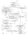
- FIG. 1illustrates the steps in an exemplary method for applying multi-level thresholding to determine the size and position of the iris image to enable extraction of iris data.
- FIG. 2illustrates an example of a captured eye image.
- FIG. 3illustrates an exemplary method for applying multi-level thresholding to create thresholded images of components in the eye image.
- FIG. 4illustrates an example of an eye histogram.
- FIG. 5Aillustrates an example of a digitally captured eye image.
- FIG. 5Billustrates the eye image of FIG. 5A after the application of a max-filter.
- FIG. 5Cillustrates the thresholded pupil image after multi-level thresholding has been executed for the eye image of FIG. 5B .
- FIG. 5Dillustrates the thresholded iris image after the multi-level thresholding has been executed for the eye image of FIG. 5B .
- FIG. 6illustrates an exemplary method for correcting uneven illumination in the eye image.
- the present inventionimplements a thresholding method where the thresholds are selected according to a nonparametric approach that considers the grey scale and does not require classifying pixels as edge or non-edge pixels.
- the present inventionavoids the need to process iteratively all images in the database for each set of image capture conditions in order to determine an edge strength threshold.
- the grey scale for each individual imageis sufficient to identify the iris in the particular image. There is no need to process a series of captured images to preselect edge strength thresholds required to find the edges in the conventional edge-detection systems. Moreover, the conditions for image capturing do not need to remain static.
- the present inventionconsiders information from the entire image in a “global” manner.
- the present inventionuses a grey scale histogram of the entire image, rather than information about edges in a localized area of the image. As a result, the location of the pupil and iris is identified at once.
- Otsuuses a non-parametric and unsupervised method of automatic threshold selection for picture segmentation.
- An optimal threshold or set of thresholdsis selected from a grey level histogram using discriminant analysis, i.e. by maximizing the between-class variance.
- Otsu's methodis considered one of the better threshold selection methods for general real world images with regard to uniformity and shape measures.
- Liao et al.propose a faster, more efficient version of Otsu's method.
- Liao et al.proposes a criterion for maximizing a modified between-class variance that is equivalent to the criterion of maximizing the between-class variance taught by Otsu's method.
- a recursive algorithmis then employed to efficiently find the optimal threshold.
- the modified between-class variancecan be pre-computed and stored in a lookup table.
- the method of Liao et al.is more efficient because the new criterion requires fewer computations and the lookup table eliminates the need to repeat arithmetic operations.
- FIG. 1illustrates an exemplary embodiment 100 of the present invention which employs a thresholding technique, such as that taught by Liao et al.
- an eye image 102is acquired.
- the image of the eyeis taken under near-infrared light in order to enhance the pattern of the iris.
- the eye imagecan be obtained by various techniques known to those of skill in the art, and thus, the details are omitted. In general, the eye image should have an even contrast across the entire eye.
- the eye image 200has a plurality of component images including a pupil image 202 , an iris image 206 , an eyelids image 212 , and an eyelashes image 214 .
- the pupil image 202has a boundary 204
- the iris image 206has an inner boundary 208 and outer boundary 210 .
- the outer boundary 204 of the pupil imagecoincides with the inner boundary 208 of the iris image 206 .
- the eyehas a distribution of grey levels.
- an optional filtermay be applied to the captured eye image 200 .
- a conventional max-filterwhich reduces pepper noise, can be applied to the image to lessen the effect of the eyelashes image 214 , which are generally thin and darker than the eyelids.
- FIG. 5Ashows an example of a digitally captured eye image
- FIG. 5Bshows the image of FIG. 5A after the application of a max-filter.
- the present inventionwhen compared to conventional approaches, is less sensitive to noise, such as noise created by eyelashes.
- the component images of the eye imageare identified according to the distribution of grey levels in the process known as multi-level thresholding.
- FIG. 3illustrates an exemplary embodiment 300 of the multi-level thresholding of step 106 .
- Liao et al.'s modified version of Otsu's methodmay be applied to process the pixels, or basic units, of the eye image and determine multiple threshold levels.
- an eye histogram 304 of pixel intensitiesis created from the distribution of grey levels in the eye image.
- the eye histogramhas classes that each correspond to one of the component images in the eye image.
- the modified between-class varianceis maximized, and in step 312 , the thresholds 314 corresponding to the classes of the eye histogram 304 are determined.
- a recursive algorithm as taught by Liao et al.is employed to efficiently find the optimal thresholds 312 .
- components of the eye imageare identified according to the calculated thresholds 314 .
- at least three threshold levelsare calculated in order to identify the pupil and iris components of the eye image, but additional threshold levels may be employed to provide more refined segmentation and to further eliminate parts of the eye image that do not correspond with the pupil and iris.
- the exemplary embodiment of the present invention described hereinemploys four thresholds. Once the threshold levels identify the pupil and iris components of the eye image, the remaining components of the image can be discarded.
- the example histogram 400 for an eye imagereveals several peaks.
- the iris imagegenerally has higher grey values than the pupil image
- the sclera imagegenerally has higher grey values than the iris image.
- the first peak 402corresponds to the pupil
- the second peak 404corresponds to the iris
- subsequent peaks 406correspond to the sclera and other parts of the eye image.
- the selected thresholds 312correspond to these identifiable peaks in the histogram 304 .
- a thresholded image corresponding to each of the classes, or component imagesis then created in step 314 .
- step 106produces a thresholded pupil image 108 and a thresholded iris image 130 corresponding to the pupil image and the iris image, respectively.
- FIGS. 5C and 5Dillustrate the thresholded pupil and iris images, respectively, after the multi-level thresholding method of step 106 is executed.
- the thresholded pupil imageis used to find the inner (pupillary) boundary of the iris image. With the further detection of the outer edge from the thresholded iris image 130 , the inner and the outer boundaries indicate the region from which iris biometric data can be obtained.
- the present inventionis robust because it is not necessary to search for parameters as required in the conventional approaches.
- the present algorithmis dynamic and adjusts itself to varying light conditions.
- the use of the present inventiondoes not depend on the database and the typical characteristics of the images in the database, unlike the approach of Wildes et al. or Canny edge detection where thresholds must be specified according to the quality of the images in the particular database.
- Otsu's methodis a notable advantage to Otsu's method is that the thresholds are not selected according to differentiation but according to integration of the histogram. Contrary to the differentiation approach of Daugman which looks for a local property, i.e. a change in luminance, Otsu's method is a global approach based on the grey level histogram reflecting the entire image. Thus, the present invention is not sensitive to localized noise or imperfections in the image. For instance, edge based algorithms fail when edges from a contact lens are present in the image. Such algorithms cannot differentiate between the edge of a contact lens and the boundary of the iris. The present invention ignores the presence of edges in favor of detecting grey scale objects which correspond to parts of the eye.
- the thresholded pupil imagemay contain pixels which do not represent the pupil image.
- extraneous parts of the imagesuch as parts of the eyelash and eyelid images, may fall within the threshold that corresponds with the pupil and become a part of the thresholded image. Therefore, referring to FIG. 1 , a process such as grey level connected component analysis is applied, in step 110 , to determine the pixels corresponding to the pupil image and separate a clean shape for the pupil from these extraneous parts.
- a simple min-max methodcan be applied to the area, in step 112 , to identify the center of the pupil and the size of the pupil.
- a circular or elliptical Hough transformcan also be applied to get pupil's size and center.
- the pupil aspect and sizeare evaluated in step 114 .
- the edgesmay be tested for circularity.
- circularitymay be tested by applying Freeman chain coding analysis, as described by H. Freeman in “Boundary encoding and processing,” Picture Processing and Psychopictorics , B. Lipkin and A. Rosenfeld, eds., Academic Press, Inc, New York, 1970, pp. 241-266. If the thresholded pupil image appears to have the proper aspect and size, the process proceeds to step 122 . In most cases, improper pupil aspect and size occur when the thresholded pupil image also includes an iris image, which causes the calculated size to be too large.
- the thresholded pupil imagemust be further processed in step 116 to segment the pupil and iris images.
- step 116applies bimodal thresholding to the thresholded pupil image.
- the steps illustrated in FIG. 3are applied in step 116 , using only two classes—one for each of the pupil image and the iris image—unlike the step 106 where more than two classes are preferably used.
- a pupil histogram 304 of pixel intensitiesis created from a distribution of grey levels in the thresholded pupil image.
- the modified between-class variances according to the method of Liao et al.are calculated and stored in a lookup table 308 to make arithmetic operations more efficient.
- step 310the modified between-class variance is maximized, and in step 312 , the thresholds 314 corresponding to the two classes in the eye histogram 304 are determined.
- the pupil and iris images of the eye imageare identified according to the calculated thresholds 314 .
- the initial thresholded pupil image 108in this case contains both a pupil image and iris image, applying bimodal thresholding to the thresholded pupil image yields a new thresholded pupil image 118 in addition to a new thresholded iris image 119 .
- the thresholded pupil image 118 from step 116may be processed again in step 120 with grey level connected component analysis.
- the thresholded iris image 119serves as input to step. 132 , which is discussed in further detail below. It should be noted that if the thresholded pupil image 108 includes pixels that correspond to the iris image, these pixels will not be included thresholded iris image 130 that result from the multi-level thresholding step 106 . As a result, the thresholded iris image 119 is necessary for processing of the iris image.
- the connected component analysis in step 120allows pixels representing non-pupil components in the thresholded image to be separated from pixels representing the pupil, further separating a clean shape for the pupil from any extraneous parts.
- the thresholded pupil imageis evaluated again in step 122 to determine whether the size and aspect of the thresholded pupil image falls within an acceptable range. As described above, the edges may be tested for circularity with a technique such as Freeman chain coding analysis. If the size and aspect of the image are acceptable, the size and position of the thresholded pupil image are verified and refined, in step 124 . Otherwise, a “pupil error” is declared in step 126 , and the captured image cannot be used to obtain biometric data.
- verifying and refining the size and position of the thresholded pupil imagemay employ an integro-differential method or the Hough circle method.
- the center and boundary of the pupilmay be determined by searching a three-parameter space for the best combination of center coordinates (x 0 , y 0 ) and radius r, i.e., where the absolute value of the partial derivative with respect to radius r of the integrated luminance along the circle is maximum.
- the pupilis modeled as a circle and the edge pixels are thinned and histogrammed into (x 0 , y 0 , r) values, where the (x 0 , y 0 , r) point with the most votes are taken to represent the pupillary boundary.
- the current inventioncan be used as a preprocessing step for conventional methods, such as those taught by Daugman, which employs an integro-differential method, or Wildes et al., which employs the Hough circle method.
- Employing the global thresholding technique of the present inventioneliminates the need to search a large parameter space as currently required by the conventional methods that rely solely on an integro-differential method or the Hough circle method.
- the step 124can verify and refine the size and position of the pupil by employing a caliper tool to detect edges, although the caliper cannot be used when no approximate location is known.
- Another possibility for the step 124includes employing a hill-climbing method on the edges.
- step 124produces a pupil size and position. If a result cannot be determined or if the result is not reasonable, a “pupil error” is declared in step 126 , and the captured image cannot be used to obtain biometric data. Otherwise, the pupil size and position 128 are used in further processing. In particular, the outer boundary of the thresholded pupil image is used to determine the inner boundary of iris image.
- the multi-level thresholding in step 106also produces a thresholded iris image 130 corresponding with the iris image.
- the outer boundary of the iris imageis determined by enhancing the edges of the thresholded iris image 130 .
- the thresholded iris image 119which results from step 116 , is used as input for step 132 in place of thresholded image 130 .
- a thresholded iris image 130 or 119is available, there is no need to use a computationally expensive edge operator for edge enhancement in step 132 .
- a very simple edge toolsuch as the Sobel edge detector, can be used.
- the Sobel edge detectoris used with angle filtering which restricts the edges to those that correspond with the center of the pupil.
- Other possible edge toolssuch as Canny, Shen-Casten, or Spacek edge detectors, can be used, but are generally more computationally expensive.
- the shape of the iris imageis determined from the thresholded iris image with enhanced edges. Determining the shape of the iris may include employing one, or a combination of, an integro-differential technique for finding a circle or ellipse, a Hough method for finding a circle or ellipse, and a least squares fit of points to a circle or ellipse.
- step 136the size and position of the iris image is verified and refined using the same approaches for the processing of the pupil image in step 124 .
- the shape finder of step 134can be seen as a “coarse find.”
- step 136produces an iris size and position. If a result cannot be determined, an “iris error” is declared in step 138 , and the captured image cannot be used to obtain biometric data. Otherwise, the thresholded iris image proceeds to the next step.
- the eye image 200also includes an eyelids image.
- the eyelids image 212forms a part of the outer boundary 210 of the iris image 206 .
- the iris imagemay be occluded by eyelids or eyelashes, the present invention produces a clean shape using thresholding, which allows any edge extraction method to work.
- the boundary of the iris imagemay be found by a circular or elliptical Hough transform or, alternatively, a circular or elliptical hill-climbing fit routine.
- the present inventionavoids the problem of isolating too much of the iris that can occur with Masek's method. Any pixels of the eye image which fall outside the calculated boundary of the iris image can be disregarded as another eye component, such an eyelid.
- step 140Once the eyelids and eyelashes are detected and eliminated in step 140 using the calculated outer boundary of the iris image, information about the iris size and position 142 can be applied to the original eye image to obtain biometric data from the iris.
- the histogramis not affected by the pixels that are a part of the same eye component but which show different grey scales due to the different amounts of light they receive.
- light reflecting off the nosecan make one side of the eye brighter and affect analysis of the image.
- Such uneven lightingcan be corrected by background analysis.
- Even with uneven lightingthe approximate positions of the pupil and iris can be identified. Therefore, the present invention may use optional shading correction to improve accuracy.
- pixel valuescan be sampled from each side of the sclera to determine the level of uneven illumination and to make appropriate corrections according to known background analysis techniques (multiplicative background analysis or background subtraction method). For instance, grey scale values can be fitted between the left and right sample pixels from the sclera and applied to the entire image. The grey level average of the left and right regions of the sclera provides an estimate of the shading.
- sample grey level values 604are sampled from the left half and the right half of the sclera image.
- step 606the difference between the left and right grey level values are determined.
- the two grey scale valuescan be used to obtain a shading difference that can be subtracted from the eye image to get a more evenly illuminated eye image 612 .
- image segmentation according to the present inventioncan be repeated in step 614 to achieve better results for locating the iris.
- the present inventionis not affected by the presence of a light spot reflection, which can confuse edge based algorithms which are looking for the type of brightness change or edge created by the spot reflection.
- a light spot reflectionis insignificant when the grey scale for a larger (pupillary) area is considered. That is, usually the spot lighting will have much higher grey scale than that of the pupil. As a result, the thresholded image for the pupil excludes the light spot.
- the present inventionuses grey scale information, it can be used to locate pupil or iris even when the edges become blurred, especially by motion.
- the processing steps of the present inventionmay be implemented on one or more computer systems or other electronic programmable devices, programmed according to the teachings of the exemplary embodiments of the present invention.
- the present inventionmay employ computer readable media or memories for holding instructions programmed according to the teachings of the present inventions and for holding data structures, tables, records, and/or other data described herein.
Landscapes
- Engineering & Computer Science (AREA)
- Physics & Mathematics (AREA)
- Health & Medical Sciences (AREA)
- General Health & Medical Sciences (AREA)
- Ophthalmology & Optometry (AREA)
- Human Computer Interaction (AREA)
- General Physics & Mathematics (AREA)
- Multimedia (AREA)
- Theoretical Computer Science (AREA)
- Computer Vision & Pattern Recognition (AREA)
- Image Processing (AREA)
- Image Analysis (AREA)
- Studio Devices (AREA)
- Facsimile Image Signal Circuits (AREA)
Abstract
Description
Claims (46)
Priority Applications (5)
| Application Number | Priority Date | Filing Date | Title |
|---|---|---|---|
| US11/526,096US7970179B2 (en) | 2006-09-25 | 2006-09-25 | Iris data extraction |
| PCT/US2007/014867WO2008091278A2 (en) | 2006-09-25 | 2007-06-27 | Iris data extraction |
| US13/096,401US8340364B2 (en) | 2006-09-25 | 2011-04-28 | Iris data extraction |
| US13/723,711US20130182953A1 (en) | 2006-09-25 | 2012-12-21 | Iris data extraction |
| US14/251,177US9235762B2 (en) | 2006-09-25 | 2014-04-11 | Iris data extraction |
Applications Claiming Priority (1)
| Application Number | Priority Date | Filing Date | Title |
|---|---|---|---|
| US11/526,096US7970179B2 (en) | 2006-09-25 | 2006-09-25 | Iris data extraction |
Related Child Applications (2)
| Application Number | Title | Priority Date | Filing Date |
|---|---|---|---|
| US13/096,401DivisionUS8340364B2 (en) | 2006-09-25 | 2011-04-28 | Iris data extraction |
| US13/096,401ContinuationUS8340364B2 (en) | 2006-09-25 | 2011-04-28 | Iris data extraction |
Publications (2)
| Publication Number | Publication Date |
|---|---|
| US20100284576A1 US20100284576A1 (en) | 2010-11-11 |
| US7970179B2true US7970179B2 (en) | 2011-06-28 |
Family
ID=39644986
Family Applications (4)
| Application Number | Title | Priority Date | Filing Date |
|---|---|---|---|
| US11/526,096Active2030-01-03US7970179B2 (en) | 2006-09-25 | 2006-09-25 | Iris data extraction |
| US13/096,401Expired - Fee RelatedUS8340364B2 (en) | 2006-09-25 | 2011-04-28 | Iris data extraction |
| US13/723,711AbandonedUS20130182953A1 (en) | 2006-09-25 | 2012-12-21 | Iris data extraction |
| US14/251,177Active2026-10-10US9235762B2 (en) | 2006-09-25 | 2014-04-11 | Iris data extraction |
Family Applications After (3)
| Application Number | Title | Priority Date | Filing Date |
|---|---|---|---|
| US13/096,401Expired - Fee RelatedUS8340364B2 (en) | 2006-09-25 | 2011-04-28 | Iris data extraction |
| US13/723,711AbandonedUS20130182953A1 (en) | 2006-09-25 | 2012-12-21 | Iris data extraction |
| US14/251,177Active2026-10-10US9235762B2 (en) | 2006-09-25 | 2014-04-11 | Iris data extraction |
Country Status (2)
| Country | Link |
|---|---|
| US (4) | US7970179B2 (en) |
| WO (1) | WO2008091278A2 (en) |
Cited By (19)
| Publication number | Priority date | Publication date | Assignee | Title |
|---|---|---|---|---|
| US20090284608A1 (en)* | 2008-05-15 | 2009-11-19 | Sungkyunkwan University Foundation For Corporate Collaboration | Gaze tracking apparatus and method using difference image entropy |
| US20140205156A1 (en)* | 2006-09-25 | 2014-07-24 | Morpho Trust USA Inc. | Iris Data Extraction |
| US20140219516A1 (en)* | 2013-02-07 | 2014-08-07 | Ittiam Systems (P) Ltd. | System and method for iris detection in digital images |
| US8885882B1 (en) | 2011-07-14 | 2014-11-11 | The Research Foundation For The State University Of New York | Real time eye tracking for human computer interaction |
| US8983146B2 (en) | 2006-05-15 | 2015-03-17 | Morphotrust Usa, Llc | Multimodal ocular biometric system |
| US20170011250A1 (en)* | 2015-07-08 | 2017-01-12 | Boris Gill | Method of Detecting Boundaries of the Human Eye |
| WO2018013199A1 (en)* | 2016-07-14 | 2018-01-18 | Magic Leap, Inc. | Iris boundary estimation using cornea curvature |
| US10402649B2 (en) | 2016-08-22 | 2019-09-03 | Magic Leap, Inc. | Augmented reality display device with deep learning sensors |
| US10445881B2 (en) | 2016-09-29 | 2019-10-15 | Magic Leap, Inc. | Neural network for eye image segmentation and image quality estimation |
| US10489680B2 (en) | 2016-10-04 | 2019-11-26 | Magic Leap, Inc. | Efficient data layouts for convolutional neural networks |
| US10521661B2 (en) | 2017-09-01 | 2019-12-31 | Magic Leap, Inc. | Detailed eye shape model for robust biometric applications |
| US10621747B2 (en) | 2016-11-15 | 2020-04-14 | Magic Leap, Inc. | Deep learning system for cuboid detection |
| US10657376B2 (en) | 2017-03-17 | 2020-05-19 | Magic Leap, Inc. | Room layout estimation methods and techniques |
| US10699420B2 (en)* | 2015-12-02 | 2020-06-30 | China Unionpay Co., Ltd. | Eyeball tracking method and apparatus, and device |
| US10719951B2 (en) | 2017-09-20 | 2020-07-21 | Magic Leap, Inc. | Personalized neural network for eye tracking |
| US10922583B2 (en) | 2017-07-26 | 2021-02-16 | Magic Leap, Inc. | Training a neural network with representations of user interface devices |
| US10922393B2 (en) | 2016-07-14 | 2021-02-16 | Magic Leap, Inc. | Deep neural network for iris identification |
| US11150777B2 (en) | 2016-12-05 | 2021-10-19 | Magic Leap, Inc. | Virtual user input controls in a mixed reality environment |
| US11537895B2 (en) | 2017-10-26 | 2022-12-27 | Magic Leap, Inc. | Gradient normalization systems and methods for adaptive loss balancing in deep multitask networks |
Families Citing this family (35)
| Publication number | Priority date | Publication date | Assignee | Title |
|---|---|---|---|---|
| FR2900482B1 (en)* | 2006-04-28 | 2008-06-20 | Sagem Defense Securite | METHOD FOR IDENTIFYING A PERSON BY ANALYZING THE CTERISTIC CARA OF ITS CILES |
| US20090252382A1 (en)* | 2007-12-06 | 2009-10-08 | University Of Notre Dame Du Lac | Segmentation of iris images using active contour processing |
| US8430173B2 (en) | 2010-04-12 | 2013-04-30 | Halliburton Energy Services, Inc. | High strength dissolvable structures for use in a subterranean well |
| CN102129685B (en)* | 2011-03-24 | 2012-08-29 | 杭州电子科技大学 | Method for detecting irregular circle based on Gauss pyramid decomposition |
| US8682073B2 (en)* | 2011-04-28 | 2014-03-25 | Sri International | Method of pupil segmentation |
| US9253448B1 (en)* | 2011-12-28 | 2016-02-02 | Cognex Corporation | System and method for determination of contact lens orientation |
| US20130259322A1 (en)* | 2012-03-31 | 2013-10-03 | Xiao Lin | System And Method For Iris Image Analysis |
| US8798332B2 (en) | 2012-05-15 | 2014-08-05 | Google Inc. | Contact lenses |
| CN103136512A (en)* | 2013-02-04 | 2013-06-05 | 重庆市科学技术研究院 | Pupil positioning method and system |
| US9968250B2 (en)* | 2014-02-24 | 2018-05-15 | Image Technologies Corporation | Autofluorescence imaging of macular pigment: image quality criteria and corrections |
| WO2015137924A1 (en)* | 2014-03-11 | 2015-09-17 | Google Inc. | Contact lenses |
| WO2016018487A2 (en)* | 2014-05-09 | 2016-02-04 | Eyefluene, Inc. | Systems and methods for biomechanically-based eye signals for interacting with real and virtual objects |
| US9412029B2 (en)* | 2014-12-12 | 2016-08-09 | Iris Id, Inc. | Apparatus for recognizing iris and operating method thereof |
| EP3267892A4 (en)* | 2015-03-13 | 2019-01-23 | Richard Awdeh | Methods and systems for regitration using a microscope insert |
| JP6918781B2 (en) | 2015-08-21 | 2021-08-11 | マジック リープ, インコーポレイテッドMagic Leap,Inc. | Eyelid shape estimation using eye pose measurement |
| JP6885935B2 (en) | 2015-10-16 | 2021-06-16 | マジック リープ, インコーポレイテッドMagic Leap,Inc. | Eye pose identification using eye features |
| CN105488494B (en)* | 2015-12-29 | 2019-01-08 | 浙江工商大学 | A kind of quick accurate localization method of iris inner boundary |
| CN105892691A (en)* | 2016-06-07 | 2016-08-24 | 京东方科技集团股份有限公司 | Method and device for controlling travel tool and travel tool system |
| WO2018016837A1 (en)* | 2016-07-18 | 2018-01-25 | Samsung Electronics Co., Ltd. | Method and apparatus for iris recognition |
| KR101854991B1 (en)* | 2016-09-12 | 2018-05-08 | 에스테 로우더, 인코포레이티드 | System and method for correcting color of digital image based on the human sclera and pupil |
| CN108229252B (en)* | 2016-12-15 | 2020-12-15 | 腾讯科技(深圳)有限公司 | Pupil positioning method and system |
| KR101776944B1 (en)* | 2017-01-09 | 2017-09-08 | 주식회사 쓰리이 | Method for coding iris pattern |
| US10275648B2 (en)* | 2017-02-08 | 2019-04-30 | Fotonation Limited | Image processing method and system for iris recognition |
| EP3430973B1 (en)* | 2017-07-19 | 2024-11-27 | Sony Group Corporation | Mobile system and method |
| US10949969B1 (en)* | 2018-03-20 | 2021-03-16 | Welch Allyn, Inc. | Pupil edge region removal in digital imaging |
| US10713483B2 (en) | 2018-03-20 | 2020-07-14 | Welch Allyn, Inc. | Pupil edge detection in digital imaging |
| CN111914585A (en)* | 2018-07-03 | 2020-11-10 | 上海斐讯数据通信技术有限公司 | Method and system for iris recognition |
| EP3826528A4 (en) | 2018-07-25 | 2022-07-27 | Natus Medical Incorporated | Real-time removal of ir led reflections from an image |
| CN109684915B (en)* | 2018-11-12 | 2021-01-01 | 温州医科大学 | Pupil Tracking Image Processing Method |
| US10855745B2 (en)* | 2018-11-29 | 2020-12-01 | Dell Products L.P. | Systems and methods for downloading data chunks using a varying number of simultaneous connections |
| CN109840484B (en)* | 2019-01-23 | 2023-03-24 | 张彦龙 | Pupil detection method based on edge filtering, ellipse evaluation and pupil verification |
| EP4010876A4 (en) | 2019-08-09 | 2022-08-24 | Nec Corporation | Information processing system, information processing method, and storage medium |
| CN111079676B (en)* | 2019-12-23 | 2022-07-19 | 浙江大学 | A kind of human iris detection method and device |
| CN111739006B (en)* | 2020-06-22 | 2021-07-13 | 深圳企业云科技股份有限公司 | Elliptical image detection algorithm and system based on enclosed road integral |
| CN116152139A (en)* | 2021-11-19 | 2023-05-23 | 北京眼神智能科技有限公司 | Color contact lens detection and iris recognition method, device, readable storage medium and equipment |
Citations (46)
| Publication number | Priority date | Publication date | Assignee | Title |
|---|---|---|---|---|
| US3069654A (en) | 1960-03-25 | 1962-12-18 | Paul V C Hough | Method and means for recognizing complex patterns |
| US4641349A (en) | 1985-02-20 | 1987-02-03 | Leonard Flom | Iris recognition system |
| US5291560A (en) | 1991-07-15 | 1994-03-01 | Iri Scan Incorporated | Biometric personal identification system based on iris analysis |
| US5572596A (en) | 1994-09-02 | 1996-11-05 | David Sarnoff Research Center, Inc. | Automated, non-invasive iris recognition system and method |
| US5859686A (en) | 1997-05-19 | 1999-01-12 | Northrop Grumman Corporation | Eye finding and tracking system |
| US5953440A (en) | 1997-12-02 | 1999-09-14 | Sensar, Inc. | Method of measuring the focus of close-up images of eyes |
| US6144754A (en) | 1997-03-28 | 2000-11-07 | Oki Electric Industry Co., Ltd. | Method and apparatus for identifying individuals |
| US6152563A (en) | 1998-02-20 | 2000-11-28 | Hutchinson; Thomas E. | Eye gaze direction tracker |
| US6215891B1 (en) | 1997-03-26 | 2001-04-10 | Oki Electric Industry Co., Ltd. | Eye image recognition method eye image selection method and system therefor |
| US6247813B1 (en) | 1999-04-09 | 2001-06-19 | Iritech, Inc. | Iris identification system and method of identifying a person through iris recognition |
| US20010017935A1 (en) | 1997-03-26 | 2001-08-30 | Oki Electric Industry Co., Ltd. | Animal identification system based on irial granule analysis |
| US6285780B1 (en) | 1997-03-28 | 2001-09-04 | Oki Electric Industry Co., Ltd. | Apparatus for identifying individual animals and image processing method |
| US6373968B2 (en) | 1997-06-06 | 2002-04-16 | Oki Electric Industry Co., Ltd. | System for identifying individuals |
| US6419638B1 (en)* | 1993-07-20 | 2002-07-16 | Sam H. Hay | Optical recognition methods for locating eyes |
| US20030012413A1 (en) | 2001-07-16 | 2003-01-16 | Matsushita Electric Industrial Co., Ltd. | Iris identification apparatus and iris image pickup apparatus |
| US6526160B1 (en) | 1998-07-17 | 2003-02-25 | Media Technology Corporation | Iris information acquisition apparatus and iris identification apparatus |
| US6532298B1 (en) | 1998-11-25 | 2003-03-11 | Iridian Technologies, Inc. | Portable authentication device and method using iris patterns |
| US20030058405A1 (en) | 2001-07-23 | 2003-03-27 | Cornsweet Tom N. | Instruments and methods for examining and quantifying cataracts |
| US6542624B1 (en) | 1998-07-17 | 2003-04-01 | Oki Electric Industry Co., Ltd. | Iris code generating device and iris identifying system |
| US6546121B1 (en) | 1998-03-05 | 2003-04-08 | Oki Electric Industry Co., Ltd. | Method and apparatus for identifying an iris |
| US6571002B1 (en) | 1999-05-13 | 2003-05-27 | Mitsubishi Denki Kabushiki Kaisha | Eye open/close detection through correlation |
| US6591064B2 (en) | 2001-07-24 | 2003-07-08 | Matsushita Electric Industrial Co., Ltd. | Iris pickup apparatus |
| US6597377B1 (en) | 1997-02-25 | 2003-07-22 | International Business Machines Corporation | Web links objects |
| US6614919B1 (en) | 1998-12-25 | 2003-09-02 | Oki Electric Industry Co., Ltd. | Method of extracting iris region and individual identification device |
| US6700998B1 (en) | 1999-04-23 | 2004-03-02 | Oki Electric Industry Co, Ltd. | Iris registration unit |
| US6714665B1 (en) | 1994-09-02 | 2004-03-30 | Sarnoff Corporation | Fully automated iris recognition system utilizing wide and narrow fields of view |
| US6753919B1 (en) | 1998-11-25 | 2004-06-22 | Iridian Technologies, Inc. | Fast focus assessment system and method for imaging |
| US6760467B1 (en) | 1999-03-23 | 2004-07-06 | Lg Electronics Inc. | Falsification discrimination method for iris recognition system |
| US6785406B1 (en) | 1999-07-19 | 2004-08-31 | Sony Corporation | Iris authentication apparatus |
| US20040197011A1 (en) | 2003-04-04 | 2004-10-07 | Camus Theodore A. | Method and apparatus for providing a robust object finder |
| US6850631B1 (en) | 1998-02-20 | 2005-02-01 | Oki Electric Industry Co., Ltd. | Photographing device, iris input device and iris image input method |
| US6944318B1 (en) | 1999-01-15 | 2005-09-13 | Citicorp Development Center, Inc. | Fast matching systems and methods for personal identification |
| US20060008124A1 (en) | 2004-07-12 | 2006-01-12 | Ewe Hong T | Iris image-based recognition system |
| US6992717B2 (en) | 2000-09-18 | 2006-01-31 | Oki Electric Industry Co., Ltd. | Iris identifying apparatus |
| US20060147094A1 (en)* | 2003-09-08 | 2006-07-06 | Woong-Tuk Yoo | Pupil detection method and shape descriptor extraction method for a iris recognition, iris feature extraction apparatus and method, and iris recognition system and method using its |
| US20060165266A1 (en) | 2005-01-26 | 2006-07-27 | Honeywell International Inc. | Iris recognition system and method |
| US7099495B2 (en) | 2001-02-28 | 2006-08-29 | Matsushita Electric Industrial Co., Ltd. | Frequency and resolution analyzed biometric authentication method and device |
| US7155035B2 (en) | 2002-02-05 | 2006-12-26 | Matsushita Electric Industrial Co., Ltd. | Personal authentication method, personal authentication apparatus and image capturing device |
| US20070036397A1 (en) | 2005-01-26 | 2007-02-15 | Honeywell International Inc. | A distance iris recognition |
| US20070047773A1 (en) | 2005-08-31 | 2007-03-01 | Stmicroelectronics S.A. | Digital processing of an iris image |
| US20070047772A1 (en) | 2005-08-25 | 2007-03-01 | Matey James R | Methods and systems for biometric identification |
| US7197166B2 (en) | 2003-01-23 | 2007-03-27 | Industrial Technology Research Institute | Iris extraction method capable of precisely determining positions and sizes of irises in a digital face image |
| US20070110284A1 (en) | 2003-12-18 | 2007-05-17 | Rieul Francois | Method and apparatus for iris recognition |
| US20070160266A1 (en) | 2006-01-11 | 2007-07-12 | Jones Michael J | Method for extracting features of irises in images using difference of sum filters |
| US20070160267A1 (en) | 2006-01-11 | 2007-07-12 | Jones Michael J | Method for localizing irises in images using gradients and textures |
| US7277561B2 (en) | 2000-10-07 | 2007-10-02 | Qritek Co., Ltd. | Iris identification |
Family Cites Families (4)
| Publication number | Priority date | Publication date | Assignee | Title |
|---|---|---|---|---|
| US2006914A (en)* | 1929-07-01 | 1935-07-02 | Fayolle Maurice | Film spacing in stereoscopic apparatus |
| US5481622A (en)* | 1994-03-01 | 1996-01-02 | Rensselaer Polytechnic Institute | Eye tracking apparatus and method employing grayscale threshold values |
| KR100374708B1 (en)* | 2001-03-06 | 2003-03-04 | 에버미디어 주식회사 | Non-contact type human iris recognition method by correction of rotated iris image |
| US7970179B2 (en)* | 2006-09-25 | 2011-06-28 | Identix Incorporated | Iris data extraction |
- 2006
- 2006-09-25USUS11/526,096patent/US7970179B2/enactiveActive
- 2007
- 2007-06-27WOPCT/US2007/014867patent/WO2008091278A2/enactiveApplication Filing
- 2011
- 2011-04-28USUS13/096,401patent/US8340364B2/ennot_activeExpired - Fee Related
- 2012
- 2012-12-21USUS13/723,711patent/US20130182953A1/ennot_activeAbandoned
- 2014
- 2014-04-11USUS14/251,177patent/US9235762B2/enactiveActive
Patent Citations (48)
| Publication number | Priority date | Publication date | Assignee | Title |
|---|---|---|---|---|
| US3069654A (en) | 1960-03-25 | 1962-12-18 | Paul V C Hough | Method and means for recognizing complex patterns |
| US4641349A (en) | 1985-02-20 | 1987-02-03 | Leonard Flom | Iris recognition system |
| US5291560A (en) | 1991-07-15 | 1994-03-01 | Iri Scan Incorporated | Biometric personal identification system based on iris analysis |
| US6419638B1 (en)* | 1993-07-20 | 2002-07-16 | Sam H. Hay | Optical recognition methods for locating eyes |
| US5572596A (en) | 1994-09-02 | 1996-11-05 | David Sarnoff Research Center, Inc. | Automated, non-invasive iris recognition system and method |
| US5751836A (en) | 1994-09-02 | 1998-05-12 | David Sarnoff Research Center Inc. | Automated, non-invasive iris recognition system and method |
| US6714665B1 (en) | 1994-09-02 | 2004-03-30 | Sarnoff Corporation | Fully automated iris recognition system utilizing wide and narrow fields of view |
| US6597377B1 (en) | 1997-02-25 | 2003-07-22 | International Business Machines Corporation | Web links objects |
| US20010017935A1 (en) | 1997-03-26 | 2001-08-30 | Oki Electric Industry Co., Ltd. | Animal identification system based on irial granule analysis |
| US6215891B1 (en) | 1997-03-26 | 2001-04-10 | Oki Electric Industry Co., Ltd. | Eye image recognition method eye image selection method and system therefor |
| US6229907B1 (en) | 1997-03-28 | 2001-05-08 | Oki Electric Industry Co., Ltd. | Method and apparatus for identifying individual |
| US6285780B1 (en) | 1997-03-28 | 2001-09-04 | Oki Electric Industry Co., Ltd. | Apparatus for identifying individual animals and image processing method |
| US6144754A (en) | 1997-03-28 | 2000-11-07 | Oki Electric Industry Co., Ltd. | Method and apparatus for identifying individuals |
| US5859686A (en) | 1997-05-19 | 1999-01-12 | Northrop Grumman Corporation | Eye finding and tracking system |
| US6373968B2 (en) | 1997-06-06 | 2002-04-16 | Oki Electric Industry Co., Ltd. | System for identifying individuals |
| US5953440A (en) | 1997-12-02 | 1999-09-14 | Sensar, Inc. | Method of measuring the focus of close-up images of eyes |
| US6850631B1 (en) | 1998-02-20 | 2005-02-01 | Oki Electric Industry Co., Ltd. | Photographing device, iris input device and iris image input method |
| US6152563A (en) | 1998-02-20 | 2000-11-28 | Hutchinson; Thomas E. | Eye gaze direction tracker |
| US6546121B1 (en) | 1998-03-05 | 2003-04-08 | Oki Electric Industry Co., Ltd. | Method and apparatus for identifying an iris |
| US6526160B1 (en) | 1998-07-17 | 2003-02-25 | Media Technology Corporation | Iris information acquisition apparatus and iris identification apparatus |
| US6542624B1 (en) | 1998-07-17 | 2003-04-01 | Oki Electric Industry Co., Ltd. | Iris code generating device and iris identifying system |
| US6532298B1 (en) | 1998-11-25 | 2003-03-11 | Iridian Technologies, Inc. | Portable authentication device and method using iris patterns |
| US6753919B1 (en) | 1998-11-25 | 2004-06-22 | Iridian Technologies, Inc. | Fast focus assessment system and method for imaging |
| US6614919B1 (en) | 1998-12-25 | 2003-09-02 | Oki Electric Industry Co., Ltd. | Method of extracting iris region and individual identification device |
| US6944318B1 (en) | 1999-01-15 | 2005-09-13 | Citicorp Development Center, Inc. | Fast matching systems and methods for personal identification |
| US6760467B1 (en) | 1999-03-23 | 2004-07-06 | Lg Electronics Inc. | Falsification discrimination method for iris recognition system |
| US6247813B1 (en) | 1999-04-09 | 2001-06-19 | Iritech, Inc. | Iris identification system and method of identifying a person through iris recognition |
| US6700998B1 (en) | 1999-04-23 | 2004-03-02 | Oki Electric Industry Co, Ltd. | Iris registration unit |
| US6571002B1 (en) | 1999-05-13 | 2003-05-27 | Mitsubishi Denki Kabushiki Kaisha | Eye open/close detection through correlation |
| US6785406B1 (en) | 1999-07-19 | 2004-08-31 | Sony Corporation | Iris authentication apparatus |
| US6992717B2 (en) | 2000-09-18 | 2006-01-31 | Oki Electric Industry Co., Ltd. | Iris identifying apparatus |
| US7277561B2 (en) | 2000-10-07 | 2007-10-02 | Qritek Co., Ltd. | Iris identification |
| US7099495B2 (en) | 2001-02-28 | 2006-08-29 | Matsushita Electric Industrial Co., Ltd. | Frequency and resolution analyzed biometric authentication method and device |
| US20030012413A1 (en) | 2001-07-16 | 2003-01-16 | Matsushita Electric Industrial Co., Ltd. | Iris identification apparatus and iris image pickup apparatus |
| US20030058405A1 (en) | 2001-07-23 | 2003-03-27 | Cornsweet Tom N. | Instruments and methods for examining and quantifying cataracts |
| US6591064B2 (en) | 2001-07-24 | 2003-07-08 | Matsushita Electric Industrial Co., Ltd. | Iris pickup apparatus |
| US7155035B2 (en) | 2002-02-05 | 2006-12-26 | Matsushita Electric Industrial Co., Ltd. | Personal authentication method, personal authentication apparatus and image capturing device |
| US7197166B2 (en) | 2003-01-23 | 2007-03-27 | Industrial Technology Research Institute | Iris extraction method capable of precisely determining positions and sizes of irises in a digital face image |
| US20040197011A1 (en) | 2003-04-04 | 2004-10-07 | Camus Theodore A. | Method and apparatus for providing a robust object finder |
| US20060147094A1 (en)* | 2003-09-08 | 2006-07-06 | Woong-Tuk Yoo | Pupil detection method and shape descriptor extraction method for a iris recognition, iris feature extraction apparatus and method, and iris recognition system and method using its |
| US20070110284A1 (en) | 2003-12-18 | 2007-05-17 | Rieul Francois | Method and apparatus for iris recognition |
| US20060008124A1 (en) | 2004-07-12 | 2006-01-12 | Ewe Hong T | Iris image-based recognition system |
| US20070036397A1 (en) | 2005-01-26 | 2007-02-15 | Honeywell International Inc. | A distance iris recognition |
| US20060165266A1 (en) | 2005-01-26 | 2006-07-27 | Honeywell International Inc. | Iris recognition system and method |
| US20070047772A1 (en) | 2005-08-25 | 2007-03-01 | Matey James R | Methods and systems for biometric identification |
| US20070047773A1 (en) | 2005-08-31 | 2007-03-01 | Stmicroelectronics S.A. | Digital processing of an iris image |
| US20070160266A1 (en) | 2006-01-11 | 2007-07-12 | Jones Michael J | Method for extracting features of irises in images using difference of sum filters |
| US20070160267A1 (en) | 2006-01-11 | 2007-07-12 | Jones Michael J | Method for localizing irises in images using gradients and textures |
Non-Patent Citations (8)
| Title |
|---|
| Christel-Loïc Tisse, et al. "Person identification technique using human iris recognition"; Advanced System Technology; Université de Montpellier. |
| Int'l Search Report for PCT/US07/14867 which claims priority to U.S. Appl. No. 11/526,096 (Jul. 17, 2008). |
| Libor Masek; "Recognition of Human Iris Patterns for Biometric Identification"; School of Computer Science and Software Engineering, The University of Western Australia, 2003. pp. 1-56. |
| Nobuyuki Otsu "A Threshold Selection Method from Gray-Level Histograms"; IEEE Transactions on Systems Man and Cybernetics, vol. SMC-9, No. I, Jan. 1979. |
| Ping-Sung Liao, et al.; "A Fast Algorithm for Multilevel Thresholding"; Journal of Information Science and Engineering 17, 713-727 (2001). |
| Written Opinion for PCT/US07/14867 which claims priority to U.S. Appl. No. 11/526,096 (Jul. 17, 2008). |
| Xiaomei Liu, et al.; "Experiments with an Improved Iris Segmentation Algorithm"; Department of Computer Science and Engineering University of Notre Dame; Fourth IEEE Workshop on Automatic Identification Advanced Technologies (AutoID), Oct. 2005, New York; 6 pages. |
| Y. Park, et al.; "A Fast Circular Edge Detector for the Iris Region Segmentation"; S.-W. Lee, H.H. Buelthoff, T. Poggio (Eds.) BMCV 2000, LNCS 1811, pp. 417-423, 2000. |
Cited By (42)
| Publication number | Priority date | Publication date | Assignee | Title |
|---|---|---|---|---|
| US8983146B2 (en) | 2006-05-15 | 2015-03-17 | Morphotrust Usa, Llc | Multimodal ocular biometric system |
| US9235762B2 (en)* | 2006-09-25 | 2016-01-12 | Morphotrust Usa, Llc | Iris data extraction |
| US20140205156A1 (en)* | 2006-09-25 | 2014-07-24 | Morpho Trust USA Inc. | Iris Data Extraction |
| US8274578B2 (en)* | 2008-05-15 | 2012-09-25 | Sungkyunkwan University Foundation For Corporate Collaboration | Gaze tracking apparatus and method using difference image entropy |
| US20090284608A1 (en)* | 2008-05-15 | 2009-11-19 | Sungkyunkwan University Foundation For Corporate Collaboration | Gaze tracking apparatus and method using difference image entropy |
| US8885882B1 (en) | 2011-07-14 | 2014-11-11 | The Research Foundation For The State University Of New York | Real time eye tracking for human computer interaction |
| US9070015B2 (en)* | 2013-02-07 | 2015-06-30 | Ittiam Systems (P) Ltd. | System and method for iris detection in digital images |
| US20140219516A1 (en)* | 2013-02-07 | 2014-08-07 | Ittiam Systems (P) Ltd. | System and method for iris detection in digital images |
| US20170011250A1 (en)* | 2015-07-08 | 2017-01-12 | Boris Gill | Method of Detecting Boundaries of the Human Eye |
| US9946929B2 (en)* | 2015-07-08 | 2018-04-17 | Boris Gill | Method of detecting boundaries of the human eye |
| US10699420B2 (en)* | 2015-12-02 | 2020-06-30 | China Unionpay Co., Ltd. | Eyeball tracking method and apparatus, and device |
| WO2018013199A1 (en)* | 2016-07-14 | 2018-01-18 | Magic Leap, Inc. | Iris boundary estimation using cornea curvature |
| US10296792B2 (en) | 2016-07-14 | 2019-05-21 | Magic Leap, Inc. | Iris boundary estimation using cornea curvature |
| US11568035B2 (en) | 2016-07-14 | 2023-01-31 | Magic Leap, Inc. | Deep neural network for iris identification |
| US10922393B2 (en) | 2016-07-14 | 2021-02-16 | Magic Leap, Inc. | Deep neural network for iris identification |
| US10733447B2 (en) | 2016-08-22 | 2020-08-04 | Magic Leap, Inc. | Augmented reality display device with deep learning sensors |
| US11797078B2 (en) | 2016-08-22 | 2023-10-24 | Magic Leap, Inc. | Augmented reality display device with deep learning sensors |
| US10402649B2 (en) | 2016-08-22 | 2019-09-03 | Magic Leap, Inc. | Augmented reality display device with deep learning sensors |
| US11120266B2 (en) | 2016-08-22 | 2021-09-14 | Magic Leap, Inc. | Augmented reality display device with deep learning sensors |
| US10445881B2 (en) | 2016-09-29 | 2019-10-15 | Magic Leap, Inc. | Neural network for eye image segmentation and image quality estimation |
| US11776131B2 (en) | 2016-09-29 | 2023-10-03 | Magic Leap, Inc. | Neural network for eye image segmentation and image quality estimation |
| US11100644B2 (en) | 2016-09-29 | 2021-08-24 | Magic Leap, Inc. | Neural network for eye image segmentation and image quality estimation |
| US11182645B2 (en) | 2016-10-04 | 2021-11-23 | Magic Leap, Inc. | Efficient data layouts for convolutional neural networks |
| US11720800B2 (en) | 2016-10-04 | 2023-08-08 | Magic Leap, Inc. | Efficient data layouts for convolutional neural networks |
| US10489680B2 (en) | 2016-10-04 | 2019-11-26 | Magic Leap, Inc. | Efficient data layouts for convolutional neural networks |
| US11328443B2 (en) | 2016-11-15 | 2022-05-10 | Magic Leap, Inc. | Deep learning system for cuboid detection |
| US11797860B2 (en) | 2016-11-15 | 2023-10-24 | Magic Leap, Inc. | Deep learning system for cuboid detection |
| US10937188B2 (en) | 2016-11-15 | 2021-03-02 | Magic Leap, Inc. | Deep learning system for cuboid detection |
| US10621747B2 (en) | 2016-11-15 | 2020-04-14 | Magic Leap, Inc. | Deep learning system for cuboid detection |
| US11150777B2 (en) | 2016-12-05 | 2021-10-19 | Magic Leap, Inc. | Virtual user input controls in a mixed reality environment |
| US11720223B2 (en) | 2016-12-05 | 2023-08-08 | Magic Leap, Inc. | Virtual user input controls in a mixed reality environment |
| US12175054B2 (en) | 2016-12-05 | 2024-12-24 | Magic Leap, Inc. | Virtual user input controls in a mixed reality environment |
| US11775835B2 (en) | 2017-03-17 | 2023-10-03 | Magic Leap, Inc. | Room layout estimation methods and techniques |
| US10657376B2 (en) | 2017-03-17 | 2020-05-19 | Magic Leap, Inc. | Room layout estimation methods and techniques |
| US11334765B2 (en) | 2017-07-26 | 2022-05-17 | Magic Leap, Inc. | Training a neural network with representations of user interface devices |
| US11630314B2 (en) | 2017-07-26 | 2023-04-18 | Magic Leap, Inc. | Training a neural network with representations of user interface devices |
| US10922583B2 (en) | 2017-07-26 | 2021-02-16 | Magic Leap, Inc. | Training a neural network with representations of user interface devices |
| US11227158B2 (en) | 2017-09-01 | 2022-01-18 | Magic Leap, Inc. | Detailed eye shape model for robust biometric applications |
| US10521661B2 (en) | 2017-09-01 | 2019-12-31 | Magic Leap, Inc. | Detailed eye shape model for robust biometric applications |
| US10719951B2 (en) | 2017-09-20 | 2020-07-21 | Magic Leap, Inc. | Personalized neural network for eye tracking |
| US10977820B2 (en) | 2017-09-20 | 2021-04-13 | Magic Leap, Inc. | Personalized neural network for eye tracking |
| US11537895B2 (en) | 2017-10-26 | 2022-12-27 | Magic Leap, Inc. | Gradient normalization systems and methods for adaptive loss balancing in deep multitask networks |
Also Published As
| Publication number | Publication date |
|---|---|
| WO2008091278A2 (en) | 2008-07-31 |
| US20130182953A1 (en) | 2013-07-18 |
| WO2008091278A3 (en) | 2008-09-25 |
| US20140205156A1 (en) | 2014-07-24 |
| US9235762B2 (en) | 2016-01-12 |
| US20110200235A1 (en) | 2011-08-18 |
| US8340364B2 (en) | 2012-12-25 |
| US20100284576A1 (en) | 2010-11-11 |
Similar Documents
| Publication | Publication Date | Title |
|---|---|---|
| US7970179B2 (en) | Iris data extraction | |
| Sutra et al. | The Viterbi algorithm at different resolutions for enhanced iris segmentation | |
| JP5107045B2 (en) | Method for identifying a pixel representing an iris in an image acquired for the eye | |
| US8280119B2 (en) | Iris recognition system using quality metrics | |
| US6885766B2 (en) | Automatic color defect correction | |
| Gangwar et al. | IrisSeg: A fast and robust iris segmentation framework for non-ideal iris images | |
| Ter Haar | Automatic localization of the optic disc in digital colour images of the human retina | |
| EP1394723A2 (en) | Method for detecting red-eye effect in digital images | |
| Frucci et al. | WIRE: Watershed based iris recognition | |
| US20100260414A1 (en) | Detecting redeye defects in digital images | |
| JP2009523265A (en) | Method for extracting iris features in an image | |
| JP2007188504A (en) | Method for filtering pixel intensity in image | |
| CN114913112B (en) | Wafer double edge detection method, device and equipment | |
| CN110263778A (en) | A kind of meter register method and device based on image recognition | |
| CN112184723B (en) | Image processing method and device, electronic equipment and storage medium | |
| CN101866420A (en) | An image preprocessing method for optical volume holographic iris recognition | |
| KR20030066512A (en) | Iris Recognition System Robust to noises | |
| Rapantzikos et al. | Nonlinear enhancement and segmentation algorithm for the detection of age-related macular degeneration (AMD) in human eye's retina | |
| Malek et al. | Automated optic disc detection in retinal images by applying region-based active aontour model in a variational level set formulation | |
| AU2020103713A4 (en) | Digital imaging methods and system for processing agar plate images for automated diagnostics | |
| Parikh et al. | Effective approach for iris localization in nonideal imaging conditions | |
| CN110956200A (en) | A tire pattern similarity detection method | |
| Adam et al. | Reliable eyelid localization for iris recognition | |
| CN107368771B (en) | Method and device for positioning license plate | |
| Ghodrati et al. | Localization of noncircular iris boundaries using morphology and arched Hough transform |
Legal Events
| Date | Code | Title | Description |
|---|---|---|---|
| AS | Assignment | Owner name:SQUARE 1 BANK, NORTH CAROLINA Free format text:SECURITY AGREEMENT;ASSIGNOR:RETICA SYSTEMS, INC.;REEL/FRAME:022259/0929 Effective date:20090213 | |
| AS | Assignment | Owner name:RETICA SYSTEMS, INC., MASSACHUSETTS Free format text:RELEASE BY SECURED PARTY;ASSIGNOR:SQUARE 1 BANK;REEL/FRAME:024170/0501 Effective date:20100323 | |
| AS | Assignment | Owner name:IDENTIX INCORPORATED, MINNESOTA Free format text:ASSIGNMENT OF ASSIGNORS INTEREST;ASSIGNOR:RETICA SYSTEMS, INC.;REEL/FRAME:024662/0643 Effective date:20100324 | |
| STCF | Information on status: patent grant | Free format text:PATENTED CASE | |
| FEPP | Fee payment procedure | Free format text:PAYOR NUMBER ASSIGNED (ORIGINAL EVENT CODE: ASPN); ENTITY STATUS OF PATENT OWNER: LARGE ENTITY | |
| AS | Assignment | Owner name:MORPHOTRUST USA, INC., MASSACHUSETTS Free format text:MERGER;ASSIGNOR:IDENTIX INCORPORATED;REEL/FRAME:031359/0917 Effective date:20121228 | |
| FPAY | Fee payment | Year of fee payment:4 | |
| FEPP | Fee payment procedure | Free format text:MAINTENANCE FEE REMINDER MAILED (ORIGINAL EVENT CODE: REM.); ENTITY STATUS OF PATENT OWNER: LARGE ENTITY | |
| FEPP | Fee payment procedure | Free format text:7.5 YR SURCHARGE - LATE PMT W/IN 6 MO, LARGE ENTITY (ORIGINAL EVENT CODE: M1555); ENTITY STATUS OF PATENT OWNER: LARGE ENTITY | |
| MAFP | Maintenance fee payment | Free format text:PAYMENT OF MAINTENANCE FEE, 8TH YEAR, LARGE ENTITY (ORIGINAL EVENT CODE: M1552); ENTITY STATUS OF PATENT OWNER: LARGE ENTITY Year of fee payment:8 | |
| MAFP | Maintenance fee payment | Free format text:PAYMENT OF MAINTENANCE FEE, 12TH YEAR, LARGE ENTITY (ORIGINAL EVENT CODE: M1553); ENTITY STATUS OF PATENT OWNER: LARGE ENTITY Year of fee payment:12 | |
| AS | Assignment | Owner name:MORPHOTRUST USA, LLC, MASSACHUSETTS Free format text:CHANGE OF NAME;ASSIGNOR:MORPHOTRUST USA, INC;REEL/FRAME:065219/0737 Effective date:20131213 | |
| AS | Assignment | Owner name:IDEMIA IDENTITY & SECURITY USA LLC, VIRGINIA Free format text:CHANGE OF NAME;ASSIGNOR:MORPHOTRUST USA, LLC;REEL/FRAME:065477/0170 Effective date:20171228 |