US7969488B2 - Correction of cluster defects in imagers - Google Patents
Correction of cluster defects in imagersDownload PDFInfo
- Publication number
- US7969488B2 US7969488B2US11/195,688US19568805AUS7969488B2US 7969488 B2US7969488 B2US 7969488B2US 19568805 AUS19568805 AUS 19568805AUS 7969488 B2US7969488 B2US 7969488B2
- Authority
- US
- United States
- Prior art keywords
- pixel
- pixels
- defective
- pairs
- pair
- Prior art date
- Legal status (The legal status is an assumption and is not a legal conclusion. Google has not performed a legal analysis and makes no representation as to the accuracy of the status listed.)
- Active, expires
Links
Images


Classifications
- H—ELECTRICITY
- H04—ELECTRIC COMMUNICATION TECHNIQUE
- H04N—PICTORIAL COMMUNICATION, e.g. TELEVISION
- H04N25/00—Circuitry of solid-state image sensors [SSIS]; Control thereof
- H04N25/60—Noise processing, e.g. detecting, correcting, reducing or removing noise
- H04N25/68—Noise processing, e.g. detecting, correcting, reducing or removing noise applied to defects
- H—ELECTRICITY
- H04—ELECTRIC COMMUNICATION TECHNIQUE
- H04N—PICTORIAL COMMUNICATION, e.g. TELEVISION
- H04N2209/00—Details of colour television systems
- H04N2209/04—Picture signal generators
- H04N2209/041—Picture signal generators using solid-state devices
- H04N2209/042—Picture signal generators using solid-state devices having a single pick-up sensor
- H04N2209/045—Picture signal generators using solid-state devices having a single pick-up sensor using mosaic colour filter
- H04N2209/046—Colour interpolation to calculate the missing colour values
Definitions
- the inventionrelates generally to the field of solid state imager devices, and more particularly to methods of correcting pixel defects in a solid state imager device.
- Solid state imagersincluding charge coupled devices (CCD) and CMOS imagers, have been used in photo imaging applications.
- a solid state imager circuitincludes a focal plane array of pixel cells, each one of the cells including a photosensor, which may be a photogate, photoconductor or a photodiode having a doped region for accumulating photo-generated charge.
- Image acquisition semiconductor devicesare especially sensitive to defects.
- a bad pixel in an imaging semiconductorwill show up as a bad area on the acquired.
- the defective pixelsmay not work at all or, alternatively, may be significantly brighter or dimmer than expected for a given light intensity.
- a single defective pixelmay sometimes be sufficient to cause the device containing the pixel to be discarded.
- One simple technique for single defective pixel correctioninvolves taking a signal from each pixel and storing the pixel values in memory. During image processing, the saved value for a defective pixel can be replaced by the average signal value of the neighboring pixels. These simple methods, however, are not viable for all pixel defects, for example, those suffering from excessive dark current. Other more complicated methods have been devised that can also correct defective pixels, including dark current pixels. For example, see the method discussed in the paper submitted by B. Dierickx and G. Meyanants “Missing Correction Method for Image Sensors,” submitted for Europto-SPIE/AFPAEC May 18-21, 1998.
- cluster defectsCorrection of multiple defects in a small area of an array, termed cluster defects, however, still remain a significant challenge. Accordingly, there is a need and desire for a method of correcting defective pixel clusters to improve the yield of imager manufacturing.
- the inventionin various exemplary embodiments, relates to a method and apparatus that allows for the correction of defective pixel clusters in an imaging device.
- the method and implementing apparatusselects a correction kernel, which includes neighboring pixel pairs, for an area identified as including defective pixels, determines average and difference output signal values for pixel pairs in the correction kernel, and substitutes a readout signal for the defective pixel output signal during image processing.
- the substituted read out signalis selected from a valid, neighboring pixel pair, which is a pair without a defective pixel and having the lowest difference in signal value.
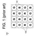
- FIG. 1is a top-down view of a conventional microlens and color filter array used in connection with a pixel array;
- FIG. 2Adepicts a correction kernel for a defective red or blue pixel of a pixel array in accordance with the invention
- FIG. 2Bdepicts a correction kernel for a defective green pixel of a pixel array in accordance with the invention
- FIG. 3depicts the correction kernel of FIG. 1 in more detail
- FIG. 4shows a flow chart of an method for correcting a pixel defect in accordance with an exemplary method of the invention
- FIG. 5shows a block diagram of an imager constructed in accordance with an exemplary embodiment of the invention.
- FIG. 6shows a processor system incorporating at least one imaging device constructed in accordance with an embodiment of the invention.
- pixelrefers to a photo-element unit cell containing a photosensor device and associated structures for converting photons to an electrical signal.
- a single representative three-color pixel arrayis illustrated in the figures and description herein.
- the inventionmay be applied to monochromatic imagers as well as to imagers for sensing fewer than three or more than three color components in an array. Accordingly, the following detailed description is not to be taken in a limiting sense, and the scope of the present invention is defined only by the appended claims.
- pixels 130are referred to by color (i.e., “red pixel,” “blue pixel,” etc.) when a color filter 120 ( FIG. 1 ) is used in connection with the pixel to focus a particular wavelength range of light, corresponding to a particular color, onto the pixel.
- FIG. 1depicts a conventional color filter array, arranged in a Bayer pattern, covering a pixel array to focus the incoming light thereat. Accordingly, when the term “red pixel” is used herein, it is referring to a pixel with a red color filter. Filters of other colors similarly filter wavelength ranges corresponding to the color to which they refer.
- Median defect correctionis a method of assigning a single defective pixel the value of a neighboring pixel. This method does not work on defect clusters, although it remains a viable option for fixing single pixel defects.
- a simple example of median correctionstarts with an imaging circuit for image processing, such as image processor 280 ( FIG. 5 ), which is provided with or determines a location of a defective pixel. The defect may be identified by the imaging circuit comparing each pixel signal to those of neighboring pixels and recognizing that one pixel has a value that is significantly out-of-range in comparison.
- the image processorrecognizes this mistake and assigns that defective pixel the average value of the neighboring pixels of the same color.
- This methoddoes not work on pixel clusters, which can be defined as two or more defective pixels of the same color within a three-by-three grid of pixels in an array.
- Median defect correctiondoes not work on cluster defects because with a defect cluster, one of the neighboring pixels also has a defective value, and therefore, the median value can not be used for substitution.
- An alternative method for correcting defective pixelsoccurs during manufacture, when defective pixels may be identified by fuses or provided in a stage area attached to an image processor. This method may be effective to correct cluster defects as well as individual defect pixels. To correct defective pixels, the location of which are part of a cluster, the defects are determined during image sensor manufacturing and production testing. Such pixels may be labeled with fuses in order to be identified during normal operation, by for example, giving the defective pixel a value of “0.” The imaging circuit ensures that the value reaches the defect correction circuitry unchanged. When a pixel with a value of “0” comes into the defect correction block, it is corrected based upon the value of its neighbors.
- a defect correction methodis performed, preferably by a correction circuit in a color processing pipeline, to correct cluster defects.
- defect correctionsincluding median defect correction, may be performed simultaneously to correct single pixels as described above.
- Cluster defect correctionhas the highest priority and in the normal operation mode it will supersede median defect correction.
- Cluster defect correctionworks on those pixels 32 ( FIGS. 2A , 2 B) that are labeled as part of a defective cluster, either with fuses, or by any other suitable identification technique.
- FIGS. 2A , 2 Billustrate parts of pixel arrays 100 , 110 , respectively, each having a respective defective pixel 32 a , 32 b that will undergo a cluster defect corrective method in accordance with the invention.
- Pixel array 100has a located defective pixel 32 a of a cluster, which can be either a red or a blue pixel.
- Pixel array 110has a defective pixel 32 b that represents a green pixel. It should be noted that in order for pixels 32 a , 32 b to be considered part of a defect cluster, at least one neighboring pixel of the same color, as shown in the Figures, must also be identified as defective.
- the pixel arrays 100 , 110are associated with a Bayer pattern color filter array 150 ( FIG. 1 ); however, the invention may also be used with other color filter patterns.
- the color filters 120focus incoming light of a particular wavelength range onto the underlying pixels 130 .
- every other pixel array rowconsists of alternating red (R) and green (G) colored pixels, while the other rows consist of alternating green (G) and blue (B) color pixels.
- the present inventionutilizes values of first and second nearest neighbor pairs of the identified, defective pixel 32 a , 32 b . These neighbors are collectively referred to herein as a defect correction kernel, shown in FIGS. 2A and 2B respectively as 101 a , 101 b . A total of eight neighbor pixels are included in each correction kernel 101 a , 101 b . It should be noted, that the illustrated correction kernels 101 a , 101 b are exemplary, and that other correction kernels may be chosen for pixel arrays using color filter patterns other than the Bayer pattern. In addition, a correction kernel could encompass more or less than eight neighboring pixels if desired.
- the exemplary correction kernels 101 a , 101 bare outlined with a dotted line.
- kernel 101 athere are eight pixels ( 10 , 12 , 14 , 34 , 54 , 52 , 50 , and 30 ) having the same color as the defective pixel 32 a .
- correction kernel 101 acontains sixteen pixels, it should be noted that half of these would be green pixels, whose signals would not be considered for use in correction of a red or blue pixel 32 a .
- the actual pixels that make up kernel 101 aare shown in greater detail in FIG. 3 .
- kernel 101 bthere are also eight pixels ( 12 , 23 , 34 , 43 , 52 , 41 , 30 , and 21 ) having the same green color as the defective pixel 32 b.
- each pixelhas a value that represents an amount of light received at the pixel.
- Vsigrepresents a readout signal
- the valueis a digitized representation of the signal.
- the valuesrange from 1 for dark pixels to 1023 for saturated pixels. These values are represented in the following description as P x where “P” is the value and “x” is the pixel number shown in FIGS. 2A and 2B .
- the defective pixels 32 a , 32 bare located by processing circuitry using any known defect location technique. The value of these pixels is pre-set to “0” as one means of clearly identifying the defective pixels.
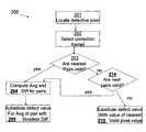
- the selection kernel 101 a for a cluster-labeled, defective pixel 32( FIG. 3 ) is selected.
- each of the pixels symmetrically located around the defective pixel 32 aare evaluated during step 203 . If an opposing pair of the pixels has two good (i.e., non-defective) pixels, the pair is regarded as a valid pair and the method 200 proceeds to step 204 . Otherwise, when at least one pixel in the pair is defective, then the pair is declared invalid and discarded from further consideration; further in this case, the method 200 continues at step 214 .
- the first pixel pair considered with respect to defective pixel 32 amay be pixel pair 12 , 52 . If one of the two pixels is defective, the pixel pair 12 , 52 is no longer considered.
- the other pixel pairs for defective pixel 32 aare 30 , 34 ; 10 , 54 ; and 14 , 50 .
- and A(P 12 +P 52 )/2 are calculated. If the two closest pixel pairs 12 , 52 and 30 , 34 are both valid, the average value A of one of the pixel pairs is then substituted, at step 205 , as the value for the defective pixel P 32a . Of the average values A for the two pixel pairs 12 , 52 and 30 , 34 , the average value A from the pixel pair with the lowest difference D is substituted as the value P 32a for pixel 32 a.
- step 203If, on the other hand, one of the nearest pixel pairs is invalid at step 203 , the next nearest pixel pairs 10 , 54 and 14 , 50 are then evaluated for valid pairs. If valid pixel pairs are found in step 214 , the method then continues at step 204 and the calculations discussed above with regard to this step are repeated for the valid pixel pairs before moving to step 205 to complete value substitution. Thus, in step 204 , an average A and a difference D is calculated for each valid pixel pair. Assuming there are multiple valid pixel pairs, either from step 203 or step 214 , then at step 205 , the average value A for the pixel pair having the lowest difference D is substituted for the value P 32a for pixel 32 a.
- step 215the pixel value P x for the nearest, same color, non-defective pixel “X” is substituted for the value P 32a of the defect pixel 32 a.
- FIG. 5illustrates an exemplary imaging device 300 having a pixel array 240 .
- Row lines of the array 240are selectively activated by a row driver 245 in response to row address decoder 255 .
- a column driver 260 and column address decoder 270are also included in the imaging device 300 .
- the imaging device 300is operated by the timing and control circuit 250 , which controls the address decoders 255 , 270 .
- the control circuit 250also controls the row and column driver circuitry 245 , 260 .
- a sample and hold circuit 261 associated with the column driver 260reads a pixel reset signal Vrst and a pixel image signal Vsig for selected pixels of the array 240 .
- a differential signal(Vrst ⁇ Vsig) is produced by differential amplifier 262 for each pixel and is digitized by analog-to-digital converter 275 (ADC).
- ADCanalog-to-digital converter 275
- the analog-to-digital converter 275supplies the digitized pixel signals to an image processor 280 which forms and may output a digital image.
- the image processor 280has a circuit that is capable of performing the method 200 for cluster defect correction on pixel array 240 .
- FIG. 6shows system 1100 , a typical processor system modified to include the imaging device 300 ( FIG. 5 ) of the invention.
- the system 1100is exemplary of a system having digital circuits that could include image sensor devices. Without being limiting, such a system could include a computer system, still or video camera system, scanner, machine vision, video phone, and auto focus system, or other imager applications.
- System 1100for example a camera system, generally comprises a central processing unit (CPU) 1102 , such as a microprocessor, that communicates with an input/output (I/O) device 1106 over a bus 1104 .
- Imaging device 300also communicates with the CPU 1102 over the bus 1104 .
- the processor-based system 1100also includes random access memory (RAM) 1110 , and can include removable memory 1115 , such as flash memory, which also communicate with the CPU 1102 over the bus 1104 .
- the imaging device 300may be combined with a processor, such as a CPU, digital signal processor, or microprocessor, with or without memory storage on a single integrated circuit or on a different chip than the processor.
Landscapes
- Engineering & Computer Science (AREA)
- Multimedia (AREA)
- Signal Processing (AREA)
- Color Television Image Signal Generators (AREA)
- Transforming Light Signals Into Electric Signals (AREA)
Abstract
Description
Claims (27)
Priority Applications (2)
| Application Number | Priority Date | Filing Date | Title |
|---|---|---|---|
| US11/195,688US7969488B2 (en) | 2005-08-03 | 2005-08-03 | Correction of cluster defects in imagers |
| US13/112,182US8817135B2 (en) | 2005-08-03 | 2011-05-20 | Correction of cluster defects in imagers |
Applications Claiming Priority (1)
| Application Number | Priority Date | Filing Date | Title |
|---|---|---|---|
| US11/195,688US7969488B2 (en) | 2005-08-03 | 2005-08-03 | Correction of cluster defects in imagers |
Related Child Applications (1)
| Application Number | Title | Priority Date | Filing Date |
|---|---|---|---|
| US13/112,182ContinuationUS8817135B2 (en) | 2005-08-03 | 2011-05-20 | Correction of cluster defects in imagers |
Publications (2)
| Publication Number | Publication Date |
|---|---|
| US20070030365A1 US20070030365A1 (en) | 2007-02-08 |
| US7969488B2true US7969488B2 (en) | 2011-06-28 |
Family
ID=37717274
Family Applications (2)
| Application Number | Title | Priority Date | Filing Date |
|---|---|---|---|
| US11/195,688Active2028-05-27US7969488B2 (en) | 2005-08-03 | 2005-08-03 | Correction of cluster defects in imagers |
| US13/112,182Active2027-03-05US8817135B2 (en) | 2005-08-03 | 2011-05-20 | Correction of cluster defects in imagers |
Family Applications After (1)
| Application Number | Title | Priority Date | Filing Date |
|---|---|---|---|
| US13/112,182Active2027-03-05US8817135B2 (en) | 2005-08-03 | 2011-05-20 | Correction of cluster defects in imagers |
Country Status (1)
| Country | Link |
|---|---|
| US (2) | US7969488B2 (en) |
Cited By (5)
| Publication number | Priority date | Publication date | Assignee | Title |
|---|---|---|---|---|
| US20090136150A1 (en)* | 2007-11-26 | 2009-05-28 | Micron Technology, Inc. | Method and apparatus for reducing image artifacts based on aperture-driven color kill with color saturation assessment |
| US20100020205A1 (en)* | 2006-09-14 | 2010-01-28 | Kozo Ishida | Image processing apparatus and imaging apparatus and method |
| US20100149386A1 (en)* | 2008-12-11 | 2010-06-17 | Itt Manufacturing Enterprises, Inc. | Pixel replacement using five nearest neighbors |
| US20100182463A1 (en)* | 2006-03-15 | 2010-07-22 | Qualcomm Incorporated | Processing of sensor values in imaging systems |
| US20160142658A1 (en)* | 2014-11-17 | 2016-05-19 | Young Sung CHO | Method of removing a bad pixel from a pixel image generated by an image sensor, an image sensor using the method, and an application processor using the method |
Families Citing this family (84)
| Publication number | Priority date | Publication date | Assignee | Title |
|---|---|---|---|---|
| JP2008018047A (en)* | 2006-07-13 | 2008-01-31 | Fujifilm Corp | Defect area correction apparatus and method, program, and radiation detection apparatus |
| US7813586B2 (en)* | 2006-08-07 | 2010-10-12 | Mela Sciences, Inc. | Reducing noise in digital images |
| US20100306318A1 (en)* | 2006-09-28 | 2010-12-02 | Sfgt Inc. | Apparatuses, methods, and systems for a graphical code-serving interface |
| JP2010506263A (en)* | 2006-09-28 | 2010-02-25 | エスエフジーティー・インコーポレイティッド | Apparatus, method and system for querying and providing code incentive information |
| DK3876510T3 (en) | 2008-05-20 | 2024-11-11 | Adeia Imaging Llc | CAPTURE AND PROCESSING OF IMAGES USING MONOLITHIC CAMERA ARRAY WITH HETEROGENEOUS IMAGES |
| US8866920B2 (en) | 2008-05-20 | 2014-10-21 | Pelican Imaging Corporation | Capturing and processing of images using monolithic camera array with heterogeneous imagers |
| US11792538B2 (en) | 2008-05-20 | 2023-10-17 | Adeia Imaging Llc | Capturing and processing of images including occlusions focused on an image sensor by a lens stack array |
| JP5402349B2 (en)* | 2009-07-23 | 2014-01-29 | ソニー株式会社 | Solid-state imaging device, driving method thereof, and electronic apparatus |
| EP2502115A4 (en) | 2009-11-20 | 2013-11-06 | Pelican Imaging Corp | CAPTURE AND IMAGE PROCESSING USING A MONOLITHIC CAMERAS NETWORK EQUIPPED WITH HETEROGENEOUS IMAGERS |
| US8928793B2 (en) | 2010-05-12 | 2015-01-06 | Pelican Imaging Corporation | Imager array interfaces |
| US8878950B2 (en) | 2010-12-14 | 2014-11-04 | Pelican Imaging Corporation | Systems and methods for synthesizing high resolution images using super-resolution processes |
| US9113145B2 (en) | 2011-03-25 | 2015-08-18 | Semiconductor Components Industries, Llc | Contrast matching for stereo image |
| US8675971B2 (en) | 2011-03-25 | 2014-03-18 | Aptina Imaging Corporation | Method and apparatus for classifying image pixels |
| EP2708019B1 (en) | 2011-05-11 | 2019-10-16 | FotoNation Limited | Systems and methods for transmitting and receiving array camera image data |
| US20130265459A1 (en) | 2011-06-28 | 2013-10-10 | Pelican Imaging Corporation | Optical arrangements for use with an array camera |
| KR20140045458A (en) | 2011-06-28 | 2014-04-16 | 펠리칸 이매징 코포레이션 | Optical arrangements for use with an array camera |
| US20130070060A1 (en) | 2011-09-19 | 2013-03-21 | Pelican Imaging Corporation | Systems and methods for determining depth from multiple views of a scene that include aliasing using hypothesized fusion |
| CN104081414B (en) | 2011-09-28 | 2017-08-01 | Fotonation开曼有限公司 | Systems and methods for encoding and decoding light field image files |
| EP2817955B1 (en) | 2012-02-21 | 2018-04-11 | FotoNation Cayman Limited | Systems and methods for the manipulation of captured light field image data |
| US9210392B2 (en) | 2012-05-01 | 2015-12-08 | Pelican Imaging Coporation | Camera modules patterned with pi filter groups |
| JP2015534734A (en) | 2012-06-28 | 2015-12-03 | ペリカン イメージング コーポレイション | System and method for detecting defective camera arrays, optical arrays, and sensors |
| US20140002674A1 (en) | 2012-06-30 | 2014-01-02 | Pelican Imaging Corporation | Systems and Methods for Manufacturing Camera Modules Using Active Alignment of Lens Stack Arrays and Sensors |
| PL4296963T3 (en) | 2012-08-21 | 2025-04-28 | Adeia Imaging Llc | Method for depth detection in images captured using array cameras |
| WO2014032020A2 (en) | 2012-08-23 | 2014-02-27 | Pelican Imaging Corporation | Feature based high resolution motion estimation from low resolution images captured using an array source |
| US9214013B2 (en) | 2012-09-14 | 2015-12-15 | Pelican Imaging Corporation | Systems and methods for correcting user identified artifacts in light field images |
| EP4307659A1 (en) | 2012-09-28 | 2024-01-17 | Adeia Imaging LLC | Generating images from light fields utilizing virtual viewpoints |
| TWI495862B (en)* | 2012-10-04 | 2015-08-11 | Pixart Imaging Inc | Method of testing image sensor and realted apparatus thereof |
| WO2014078443A1 (en) | 2012-11-13 | 2014-05-22 | Pelican Imaging Corporation | Systems and methods for array camera focal plane control |
| US9462164B2 (en) | 2013-02-21 | 2016-10-04 | Pelican Imaging Corporation | Systems and methods for generating compressed light field representation data using captured light fields, array geometry, and parallax information |
| US9374512B2 (en) | 2013-02-24 | 2016-06-21 | Pelican Imaging Corporation | Thin form factor computational array cameras and modular array cameras |
| US9774789B2 (en) | 2013-03-08 | 2017-09-26 | Fotonation Cayman Limited | Systems and methods for high dynamic range imaging using array cameras |
| US8866912B2 (en) | 2013-03-10 | 2014-10-21 | Pelican Imaging Corporation | System and methods for calibration of an array camera using a single captured image |
| US9888194B2 (en) | 2013-03-13 | 2018-02-06 | Fotonation Cayman Limited | Array camera architecture implementing quantum film image sensors |
| US9106784B2 (en) | 2013-03-13 | 2015-08-11 | Pelican Imaging Corporation | Systems and methods for controlling aliasing in images captured by an array camera for use in super-resolution processing |
| US9124831B2 (en) | 2013-03-13 | 2015-09-01 | Pelican Imaging Corporation | System and methods for calibration of an array camera |
| WO2014165244A1 (en) | 2013-03-13 | 2014-10-09 | Pelican Imaging Corporation | Systems and methods for synthesizing images from image data captured by an array camera using restricted depth of field depth maps in which depth estimation precision varies |
| WO2014153098A1 (en) | 2013-03-14 | 2014-09-25 | Pelican Imaging Corporation | Photmetric normalization in array cameras |
| US9578259B2 (en) | 2013-03-14 | 2017-02-21 | Fotonation Cayman Limited | Systems and methods for reducing motion blur in images or video in ultra low light with array cameras |
| US9633442B2 (en) | 2013-03-15 | 2017-04-25 | Fotonation Cayman Limited | Array cameras including an array camera module augmented with a separate camera |
| US9438888B2 (en) | 2013-03-15 | 2016-09-06 | Pelican Imaging Corporation | Systems and methods for stereo imaging with camera arrays |
| US10122993B2 (en) | 2013-03-15 | 2018-11-06 | Fotonation Limited | Autofocus system for a conventional camera that uses depth information from an array camera |
| WO2014150856A1 (en) | 2013-03-15 | 2014-09-25 | Pelican Imaging Corporation | Array camera implementing quantum dot color filters |
| US9497429B2 (en) | 2013-03-15 | 2016-11-15 | Pelican Imaging Corporation | Extended color processing on pelican array cameras |
| US9445003B1 (en) | 2013-03-15 | 2016-09-13 | Pelican Imaging Corporation | Systems and methods for synthesizing high resolution images using image deconvolution based on motion and depth information |
| CN103258478B (en)* | 2013-05-09 | 2015-04-15 | 友达光电(厦门)有限公司 | Substrate for displayer and display panel |
| US9898856B2 (en) | 2013-09-27 | 2018-02-20 | Fotonation Cayman Limited | Systems and methods for depth-assisted perspective distortion correction |
| US9264592B2 (en) | 2013-11-07 | 2016-02-16 | Pelican Imaging Corporation | Array camera modules incorporating independently aligned lens stacks |
| US10119808B2 (en) | 2013-11-18 | 2018-11-06 | Fotonation Limited | Systems and methods for estimating depth from projected texture using camera arrays |
| WO2015081279A1 (en) | 2013-11-26 | 2015-06-04 | Pelican Imaging Corporation | Array camera configurations incorporating multiple constituent array cameras |
| US10089740B2 (en) | 2014-03-07 | 2018-10-02 | Fotonation Limited | System and methods for depth regularization and semiautomatic interactive matting using RGB-D images |
| US9247117B2 (en) | 2014-04-07 | 2016-01-26 | Pelican Imaging Corporation | Systems and methods for correcting for warpage of a sensor array in an array camera module by introducing warpage into a focal plane of a lens stack array |
| US9521319B2 (en) | 2014-06-18 | 2016-12-13 | Pelican Imaging Corporation | Array cameras and array camera modules including spectral filters disposed outside of a constituent image sensor |
| JP2017531976A (en) | 2014-09-29 | 2017-10-26 | フォトネイション ケイマン リミテッド | System and method for dynamically calibrating an array camera |
| CN107004260A (en)* | 2014-12-12 | 2017-08-01 | 爱克发医疗保健公司 | For correcting the method for having flaw pixel artifact in direct radiography image |
| US9942474B2 (en) | 2015-04-17 | 2018-04-10 | Fotonation Cayman Limited | Systems and methods for performing high speed video capture and depth estimation using array cameras |
| KR102437588B1 (en)* | 2015-09-22 | 2022-08-30 | 삼성전자주식회사 | Image capturing device |
| CN105844683B (en)* | 2016-03-23 | 2019-02-05 | 深圳市富途网络科技有限公司 | The implementation method of pixel difference frame-by-frame cartoons based on Canvas and WebWorker |
| KR102049681B1 (en)* | 2016-11-30 | 2019-11-27 | 광동 오포 모바일 텔레커뮤니케이션즈 코포레이션 리미티드 | Image dead pixel compensation method, apparatus and non-transitory computer readable storage medium |
| JP6879841B2 (en)* | 2017-06-28 | 2021-06-02 | 株式会社 東京ウエルズ | Image processing method and defect inspection method |
| US10482618B2 (en) | 2017-08-21 | 2019-11-19 | Fotonation Limited | Systems and methods for hybrid depth regularization |
| DE102018003670B4 (en)* | 2018-05-05 | 2020-02-27 | Diehl Defence Gmbh & Co. Kg | Method for evaluating image data from a matrix detector |
| GB2581977B (en)* | 2019-03-05 | 2023-03-29 | Advanced Risc Mach Ltd | Pixel Correction |
| US11270110B2 (en) | 2019-09-17 | 2022-03-08 | Boston Polarimetrics, Inc. | Systems and methods for surface modeling using polarization cues |
| WO2021071992A1 (en) | 2019-10-07 | 2021-04-15 | Boston Polarimetrics, Inc. | Systems and methods for augmentation of sensor systems and imaging systems with polarization |
| DE112020005932T5 (en) | 2019-11-30 | 2023-01-05 | Boston Polarimetrics, Inc. | SYSTEMS AND METHODS FOR SEGMENTATION OF TRANSPARENT OBJECTS USING POLARIZATION CHARACTERISTICS |
| EP4081933A4 (en) | 2020-01-29 | 2024-03-20 | Intrinsic Innovation LLC | Systems and methods for characterizing object pose detection and measurement systems |
| US11797863B2 (en) | 2020-01-30 | 2023-10-24 | Intrinsic Innovation Llc | Systems and methods for synthesizing data for training statistical models on different imaging modalities including polarized images |
| US11953700B2 (en) | 2020-05-27 | 2024-04-09 | Intrinsic Innovation Llc | Multi-aperture polarization optical systems using beam splitters |
| US12020455B2 (en) | 2021-03-10 | 2024-06-25 | Intrinsic Innovation Llc | Systems and methods for high dynamic range image reconstruction |
| US12069227B2 (en) | 2021-03-10 | 2024-08-20 | Intrinsic Innovation Llc | Multi-modal and multi-spectral stereo camera arrays |
| US11954886B2 (en) | 2021-04-15 | 2024-04-09 | Intrinsic Innovation Llc | Systems and methods for six-degree of freedom pose estimation of deformable objects |
| US11290658B1 (en) | 2021-04-15 | 2022-03-29 | Boston Polarimetrics, Inc. | Systems and methods for camera exposure control |
| US12067746B2 (en) | 2021-05-07 | 2024-08-20 | Intrinsic Innovation Llc | Systems and methods for using computer vision to pick up small objects |
| US12175741B2 (en) | 2021-06-22 | 2024-12-24 | Intrinsic Innovation Llc | Systems and methods for a vision guided end effector |
| US12340538B2 (en) | 2021-06-25 | 2025-06-24 | Intrinsic Innovation Llc | Systems and methods for generating and using visual datasets for training computer vision models |
| US12172310B2 (en) | 2021-06-29 | 2024-12-24 | Intrinsic Innovation Llc | Systems and methods for picking objects using 3-D geometry and segmentation |
| US11689813B2 (en) | 2021-07-01 | 2023-06-27 | Intrinsic Innovation Llc | Systems and methods for high dynamic range imaging using crossed polarizers |
| US12293535B2 (en) | 2021-08-03 | 2025-05-06 | Intrinsic Innovation Llc | Systems and methods for training pose estimators in computer vision |
| EP4228278B1 (en) | 2022-02-15 | 2025-09-17 | Canon Kabushiki Kaisha | Pixel array correction and photoelectric conversion system |
| JP7646620B2 (en)* | 2022-02-15 | 2025-03-17 | キヤノン株式会社 | Processing device, photoelectric conversion system |
| JP7646611B2 (en)* | 2022-09-28 | 2025-03-17 | キヤノン株式会社 | Photoelectric conversion device, control method, and computer program |
| JP7686605B2 (en)* | 2022-09-28 | 2025-06-02 | キヤノン株式会社 | Photoelectric conversion device, control method, and computer program |
| JP7686607B2 (en)* | 2022-10-27 | 2025-06-02 | キヤノン株式会社 | Photoelectric conversion device, control method, and computer program |
| JP7646714B2 (en)* | 2023-02-24 | 2025-03-17 | キヤノン株式会社 | IMAGING APPARATUS, IMAGING METHOD, AND COMPUTER PROGRAM |
Citations (13)
| Publication number | Priority date | Publication date | Assignee | Title |
|---|---|---|---|---|
| JP2001307079A (en)* | 2000-04-26 | 2001-11-02 | Seiko Epson Corp | Image processing apparatus, image processing method, and recording medium |
| US20010052938A1 (en) | 2000-06-20 | 2001-12-20 | Olympus Optical Co., Ltd | Color image processing apparatus |
| US6526366B1 (en)* | 2000-05-18 | 2003-02-25 | Intel Corporation | Imaging sensor defect map storage |
| US20030179418A1 (en)* | 2002-03-19 | 2003-09-25 | Eastman Kodak Company | Producing a defective pixel map from defective cluster pixels in an area array image sensor |
| US6650789B2 (en) | 1999-09-16 | 2003-11-18 | Eastman Kodak Company | Method and system for altering defects in a digital image |
| US6683995B2 (en) | 1999-12-23 | 2004-01-27 | Eastman Kodak Company | Method and apparatus for correcting large defects in digital images |
| US6711302B1 (en) | 1999-10-20 | 2004-03-23 | Eastman Kodak Company | Method and system for altering defects in digital image |
| US20040096125A1 (en)* | 2002-11-15 | 2004-05-20 | Timothy Alderson | Method and apparatus for image processing using weighted defective pixel replacement |
| US6806902B1 (en) | 1999-06-08 | 2004-10-19 | Chrontel, Inc. | System and method for correcting bad pixel data in a digital camera |
| US20040239782A1 (en)* | 2003-05-30 | 2004-12-02 | William Equitz | System and method for efficient improvement of image quality in cameras |
| US20050024492A1 (en)* | 2003-07-03 | 2005-02-03 | Christoph Schaefer | Obstacle detection and terrain classification method |
| US20060257046A1 (en)* | 2005-05-13 | 2006-11-16 | Rai Barinder S | Apparatus and method for image noise reduction |
| US7432985B2 (en)* | 2003-03-26 | 2008-10-07 | Canon Kabushiki Kaisha | Image processing method |
- 2005
- 2005-08-03USUS11/195,688patent/US7969488B2/enactiveActive
- 2011
- 2011-05-20USUS13/112,182patent/US8817135B2/enactiveActive
Patent Citations (13)
| Publication number | Priority date | Publication date | Assignee | Title |
|---|---|---|---|---|
| US6806902B1 (en) | 1999-06-08 | 2004-10-19 | Chrontel, Inc. | System and method for correcting bad pixel data in a digital camera |
| US6650789B2 (en) | 1999-09-16 | 2003-11-18 | Eastman Kodak Company | Method and system for altering defects in a digital image |
| US6711302B1 (en) | 1999-10-20 | 2004-03-23 | Eastman Kodak Company | Method and system for altering defects in digital image |
| US6683995B2 (en) | 1999-12-23 | 2004-01-27 | Eastman Kodak Company | Method and apparatus for correcting large defects in digital images |
| JP2001307079A (en)* | 2000-04-26 | 2001-11-02 | Seiko Epson Corp | Image processing apparatus, image processing method, and recording medium |
| US6526366B1 (en)* | 2000-05-18 | 2003-02-25 | Intel Corporation | Imaging sensor defect map storage |
| US20010052938A1 (en) | 2000-06-20 | 2001-12-20 | Olympus Optical Co., Ltd | Color image processing apparatus |
| US20030179418A1 (en)* | 2002-03-19 | 2003-09-25 | Eastman Kodak Company | Producing a defective pixel map from defective cluster pixels in an area array image sensor |
| US20040096125A1 (en)* | 2002-11-15 | 2004-05-20 | Timothy Alderson | Method and apparatus for image processing using weighted defective pixel replacement |
| US7432985B2 (en)* | 2003-03-26 | 2008-10-07 | Canon Kabushiki Kaisha | Image processing method |
| US20040239782A1 (en)* | 2003-05-30 | 2004-12-02 | William Equitz | System and method for efficient improvement of image quality in cameras |
| US20050024492A1 (en)* | 2003-07-03 | 2005-02-03 | Christoph Schaefer | Obstacle detection and terrain classification method |
| US20060257046A1 (en)* | 2005-05-13 | 2006-11-16 | Rai Barinder S | Apparatus and method for image noise reduction |
Non-Patent Citations (2)
| Title |
|---|
| Johnathon Fewkes et al., Enhance picture quality using advanced camera system, Micron Technology, Inc. |
| Jonathon Fewkes et al., Enhance picture quality using advanced camera system, EE Times, China, Apr. 2005. |
Cited By (10)
| Publication number | Priority date | Publication date | Assignee | Title |
|---|---|---|---|---|
| US20100182463A1 (en)* | 2006-03-15 | 2010-07-22 | Qualcomm Incorporated | Processing of sensor values in imaging systems |
| US8077228B2 (en)* | 2006-03-15 | 2011-12-13 | Qualcomm Incorporated | Processing of sensor values in imaging systems |
| US20100020205A1 (en)* | 2006-09-14 | 2010-01-28 | Kozo Ishida | Image processing apparatus and imaging apparatus and method |
| US8154628B2 (en)* | 2006-09-14 | 2012-04-10 | Mitsubishi Electric Corporation | Image processing apparatus and imaging apparatus and method |
| US20090136150A1 (en)* | 2007-11-26 | 2009-05-28 | Micron Technology, Inc. | Method and apparatus for reducing image artifacts based on aperture-driven color kill with color saturation assessment |
| US8131072B2 (en)* | 2007-11-26 | 2012-03-06 | Aptina Imaging Corporation | Method and apparatus for reducing image artifacts based on aperture-driven color kill with color saturation assessment |
| US20100149386A1 (en)* | 2008-12-11 | 2010-06-17 | Itt Manufacturing Enterprises, Inc. | Pixel replacement using five nearest neighbors |
| US8237825B2 (en)* | 2008-12-11 | 2012-08-07 | Exelis, Inc. | Pixel replacement using five nearest neighbors |
| US20160142658A1 (en)* | 2014-11-17 | 2016-05-19 | Young Sung CHO | Method of removing a bad pixel from a pixel image generated by an image sensor, an image sensor using the method, and an application processor using the method |
| US9762827B2 (en)* | 2014-11-17 | 2017-09-12 | Samsung Electronics Co., Ltd. | Method of removing a bad pixel from a pixel image generated by an image sensor, an image sensor using the method, and an application processor using the method |
Also Published As
| Publication number | Publication date |
|---|---|
| US20070030365A1 (en) | 2007-02-08 |
| US8817135B2 (en) | 2014-08-26 |
| US20110221939A1 (en) | 2011-09-15 |
Similar Documents
| Publication | Publication Date | Title |
|---|---|---|
| US7969488B2 (en) | Correction of cluster defects in imagers | |
| US7471820B2 (en) | Correction method for defects in imagers | |
| US10334241B2 (en) | Systems and methods for detecting defective camera arrays and optic arrays | |
| US7796180B2 (en) | Method for calculating circular symmetrical microlens/color filter array shift | |
| US7015961B2 (en) | Digital image system and method for combining demosaicing and bad pixel correction | |
| US8085391B2 (en) | Integrated optical characteristic measurements in a CMOS image sensor | |
| US6965395B1 (en) | Methods and systems for detecting defective imaging pixels and pixel values | |
| US8218898B2 (en) | Method and apparatus providing noise reduction while preserving edges for imagers | |
| US20070139740A1 (en) | Image processing circuit and image processing method | |
| KR20080078044A (en) | Method and apparatus for reducing image noise | |
| US20080278609A1 (en) | Imaging apparatus, defective pixel correcting apparatus, processing method in the apparatuses, and program | |
| JPH11252464A (en) | Pixel correction system and method for CMOS imagers | |
| EP1872572B1 (en) | Generation and strorage of column offsets for a column parallel image sensor | |
| US9749554B2 (en) | Systems and methods for weighted image signal readout | |
| JP2024085387A (en) | Image sensors containing microlenses of different sizes | |
| US7741589B2 (en) | Method and apparatus providing multiple transfer gate control lines per pixel for automatic exposure control | |
| WO2009058616A1 (en) | White/black pixel correction in a digital image sensor | |
| KR20110092701A (en) | Unit pixel pattern of the photosensitive device and an optical sensing device comprising the same | |
| US20150264285A1 (en) | Image processing apparatus and solid-state imaging apparatus |
Legal Events
| Date | Code | Title | Description |
|---|---|---|---|
| AS | Assignment | Owner name:MICRON TECHNOLOGY, INC., IDAHO Free format text:ASSIGNMENT OF ASSIGNORS INTEREST;ASSIGNOR:JERDEV, DMITRI;REEL/FRAME:016857/0812 Effective date:20050728 | |
| FEPP | Fee payment procedure | Free format text:PAYOR NUMBER ASSIGNED (ORIGINAL EVENT CODE: ASPN); ENTITY STATUS OF PATENT OWNER: LARGE ENTITY | |
| STCF | Information on status: patent grant | Free format text:PATENTED CASE | |
| CC | Certificate of correction | ||
| FPAY | Fee payment | Year of fee payment:4 | |
| AS | Assignment | Owner name:U.S. BANK NATIONAL ASSOCIATION, AS COLLATERAL AGENT, CALIFORNIA Free format text:SECURITY INTEREST;ASSIGNOR:MICRON TECHNOLOGY, INC.;REEL/FRAME:038669/0001 Effective date:20160426 Owner name:U.S. BANK NATIONAL ASSOCIATION, AS COLLATERAL AGEN Free format text:SECURITY INTEREST;ASSIGNOR:MICRON TECHNOLOGY, INC.;REEL/FRAME:038669/0001 Effective date:20160426 | |
| AS | Assignment | Owner name:MORGAN STANLEY SENIOR FUNDING, INC., AS COLLATERAL AGENT, MARYLAND Free format text:PATENT SECURITY AGREEMENT;ASSIGNOR:MICRON TECHNOLOGY, INC.;REEL/FRAME:038954/0001 Effective date:20160426 Owner name:MORGAN STANLEY SENIOR FUNDING, INC., AS COLLATERAL Free format text:PATENT SECURITY AGREEMENT;ASSIGNOR:MICRON TECHNOLOGY, INC.;REEL/FRAME:038954/0001 Effective date:20160426 | |
| AS | Assignment | Owner name:U.S. BANK NATIONAL ASSOCIATION, AS COLLATERAL AGENT, CALIFORNIA Free format text:CORRECTIVE ASSIGNMENT TO CORRECT THE REPLACE ERRONEOUSLY FILED PATENT #7358718 WITH THE CORRECT PATENT #7358178 PREVIOUSLY RECORDED ON REEL 038669 FRAME 0001. ASSIGNOR(S) HEREBY CONFIRMS THE SECURITY INTEREST;ASSIGNOR:MICRON TECHNOLOGY, INC.;REEL/FRAME:043079/0001 Effective date:20160426 Owner name:U.S. BANK NATIONAL ASSOCIATION, AS COLLATERAL AGEN Free format text:CORRECTIVE ASSIGNMENT TO CORRECT THE REPLACE ERRONEOUSLY FILED PATENT #7358718 WITH THE CORRECT PATENT #7358178 PREVIOUSLY RECORDED ON REEL 038669 FRAME 0001. ASSIGNOR(S) HEREBY CONFIRMS THE SECURITY INTEREST;ASSIGNOR:MICRON TECHNOLOGY, INC.;REEL/FRAME:043079/0001 Effective date:20160426 | |
| AS | Assignment | Owner name:JPMORGAN CHASE BANK, N.A., AS COLLATERAL AGENT, ILLINOIS Free format text:SECURITY INTEREST;ASSIGNORS:MICRON TECHNOLOGY, INC.;MICRON SEMICONDUCTOR PRODUCTS, INC.;REEL/FRAME:047540/0001 Effective date:20180703 Owner name:JPMORGAN CHASE BANK, N.A., AS COLLATERAL AGENT, IL Free format text:SECURITY INTEREST;ASSIGNORS:MICRON TECHNOLOGY, INC.;MICRON SEMICONDUCTOR PRODUCTS, INC.;REEL/FRAME:047540/0001 Effective date:20180703 | |
| AS | Assignment | Owner name:MICRON TECHNOLOGY, INC., IDAHO Free format text:RELEASE BY SECURED PARTY;ASSIGNOR:U.S. BANK NATIONAL ASSOCIATION, AS COLLATERAL AGENT;REEL/FRAME:047243/0001 Effective date:20180629 | |
| MAFP | Maintenance fee payment | Free format text:PAYMENT OF MAINTENANCE FEE, 8TH YEAR, LARGE ENTITY (ORIGINAL EVENT CODE: M1552); ENTITY STATUS OF PATENT OWNER: LARGE ENTITY Year of fee payment:8 | |
| AS | Assignment | Owner name:MICRON TECHNOLOGY, INC., IDAHO Free format text:RELEASE BY SECURED PARTY;ASSIGNOR:MORGAN STANLEY SENIOR FUNDING, INC., AS COLLATERAL AGENT;REEL/FRAME:050937/0001 Effective date:20190731 | |
| AS | Assignment | Owner name:MICRON TECHNOLOGY, INC., IDAHO Free format text:RELEASE BY SECURED PARTY;ASSIGNOR:JPMORGAN CHASE BANK, N.A., AS COLLATERAL AGENT;REEL/FRAME:051028/0001 Effective date:20190731 Owner name:MICRON SEMICONDUCTOR PRODUCTS, INC., IDAHO Free format text:RELEASE BY SECURED PARTY;ASSIGNOR:JPMORGAN CHASE BANK, N.A., AS COLLATERAL AGENT;REEL/FRAME:051028/0001 Effective date:20190731 | |
| MAFP | Maintenance fee payment | Free format text:PAYMENT OF MAINTENANCE FEE, 12TH YEAR, LARGE ENTITY (ORIGINAL EVENT CODE: M1553); ENTITY STATUS OF PATENT OWNER: LARGE ENTITY Year of fee payment:12 |